Embed Size (px)
Citation preview
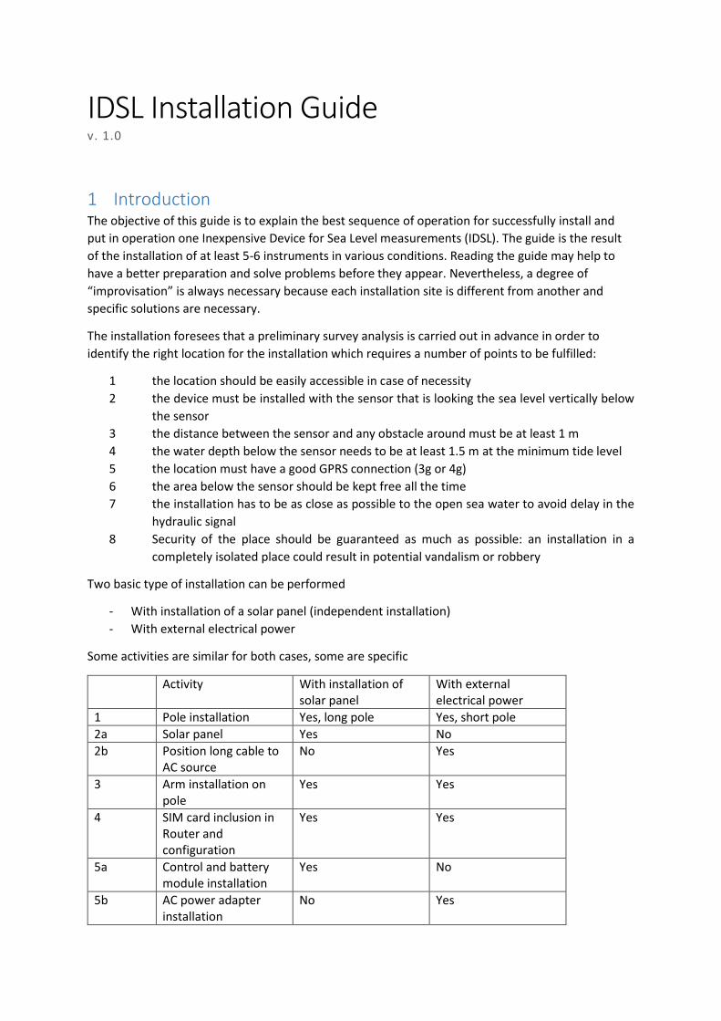
IDSL Installation Guide v. 1.0
1 Introduction The objective of this guide is to explain the best sequence of operation for successfully install and
put in operation one Inexpensive Device for Sea Level measurements (IDSL). The guide is the result
of the installation of at least 5-6 instruments in various conditions. Reading the guide may help to
have a better preparation and solve problems before they appear. Nevertheless, a degree of
“improvisation” is always necessary because each installation site is different from another and
specific solutions are necessary.
The installation foresees that a preliminary survey analysis is carried out in advance in order to
identify the right location for the installation which requires a number of points to be fulfilled:
1 the location should be easily accessible in case of necessity
2 the device must be installed with the sensor that is looking the sea level vertically below
the sensor
3 the distance between the sensor and any obstacle around must be at least 1 m
4 the water depth below the sensor needs to be at least 1.5 m at the minimum tide level
5 the location must have a good GPRS connection (3g or 4g)
6 the area below the sensor should be kept free all the time
7 the installation has to be as close as possible to the open sea water to avoid delay in the
hydraulic signal
8 Security of the place should be guaranteed as much as possible: an installation in a
completely isolated place could result in potential vandalism or robbery
Two basic type of installation can be performed
- With installation of a solar panel (independent installation)
- With external electrical power
Some activities are similar for both cases, some are specific
Activity With installation of solar panel
With external electrical power
1 Pole installation Yes, long pole Yes, short pole
2a Solar panel Yes No
2b Position long cable to AC source
No Yes
3 Arm installation on pole
Yes Yes
4 SIM card inclusion in Router and configuration
Yes Yes
5a Control and battery module installation
Yes No
5b AC power adapter installation
No Yes

6 Wires connection Yes No
7 Wind tension wires Yes Yes
8 Switch on and checking
Yes Yes
2 Pole Installation The pole installation is the most important because all the devices are then attached to the pole. So
it is necessary to select a right solid vertical wall onto which the pole with its mounting supports are
fixed. The distance between the two supports should be as large as possible compatibly with the
vertical wall characteristics. As high is the distance as low is wind induced oscillation of the pole that
is then necessary to counteract with tenso wires.
The following indications should followed, if possible:
Pole length Min Distance between supports
1.5 – 2 m 1-1.8 m Case of AC power available, no solar panel necessary
3.5-4.0 m 1.5-1.8 m Normal distance for Solar Panel
4.0-5.0 m 2.0-2.5 m Extended height to rise the Solar Panel
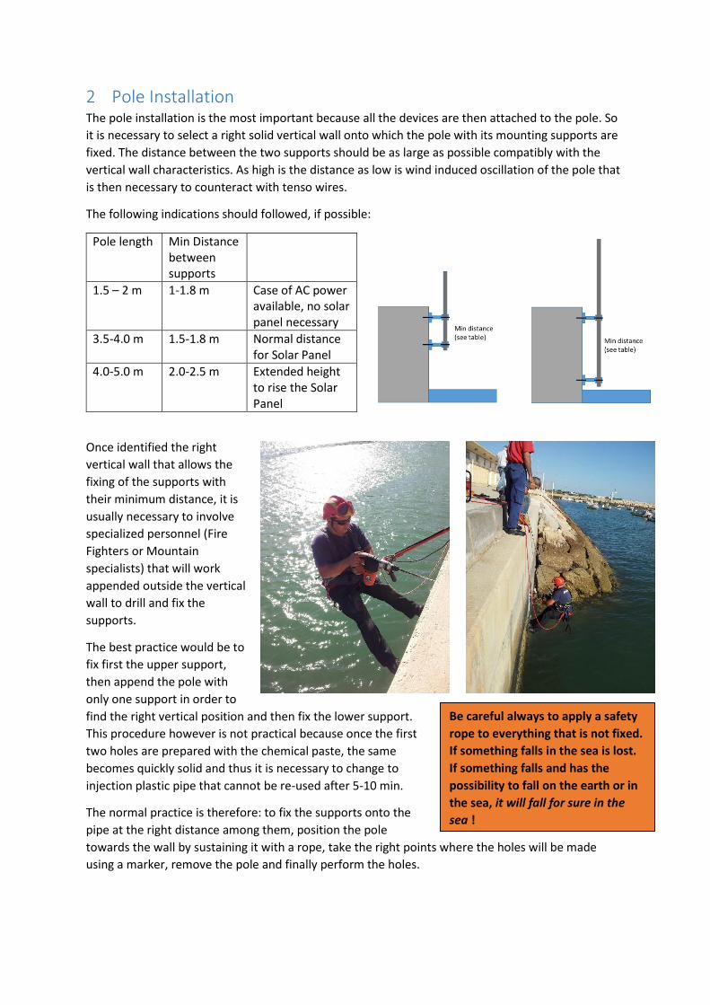
Once identified the right
vertical wall that allows the
fixing of the supports with
their minimum distance, it is
usually necessary to involve
specialized personnel (Fire
Fighters or Mountain
specialists) that will work
appended outside the vertical
wall to drill and fix the
supports.
The best practice would be to
fix first the upper support,
then append the pole with
only one support in order to
find the right vertical position and then fix the lower support.
This procedure however is not practical because once the first
two holes are prepared with the chemical paste, the same
becomes quickly solid and thus it is necessary to change to
injection plastic pipe that cannot be re-used after 5-10 min.
The normal practice is therefore: to fix the supports onto the
pipe at the right distance among them, position the pole
towards the wall by sustaining it with a rope, take the right points where the holes will be made
using a marker, remove the pole and finally perform the holes.
Be careful always to apply a safety
rope to everything that is not fixed.
If something falls in the sea is lost.
If something falls and has the
possibility to fall on the earth or in
the sea, it will fall for sure in the
sea !

In case the lower support can be part of the day
under water, it is necessary to wait the low tide in
order to perform the installation. This is more a
problem for Atlantic Ocean locations where the tide
excursion is much larger.
In case the minimum distance is not available, it is
necessary to install oblique supports as in the figure,
in order to maintain the min distance between the
upper and the lower support.
The installation of the two supports should be done
using chemical anchors: a special resin inside which a
screwable anchor will be positioned. The time for
having a perfect blockage depends by the
Temperature and by the type of material applied and
should be consulted on the material technical
specification. It is essential to install these with the
maximum precision and fixing quality because all the
installation depends on those 4 anchors. Example of
fixing procedure is indicated below.
What is a Chemical Anchor?
chemical or resin anchors are generic terms
relating to steel studs, bolts and
anchorages which are bonded into a
substrate, usually masonry and concrete,
using a resin based adhesive system. Ideally
suited for high load applications, in
virtually all cases the resulting bond is
stronger than the base material itself. As
the system is based on chemical adhesion,
no load stress is imparted to the base
material as with expansion type anchors
and are therefore ideal for close to edge
fixing, reduced center and group anchoring
and use in concrete of unknown quality or
low compressive strength. Although there
are many differing variations and delivery
systems in the market, all systems operate
using the same basic principle with the
base resin, requiring the introduction, by
mixing, of a second component to begin the
chemical curing process, hence the term
chemical anchor
http://www.constructionfixings.com/chemicalanchoring.htm
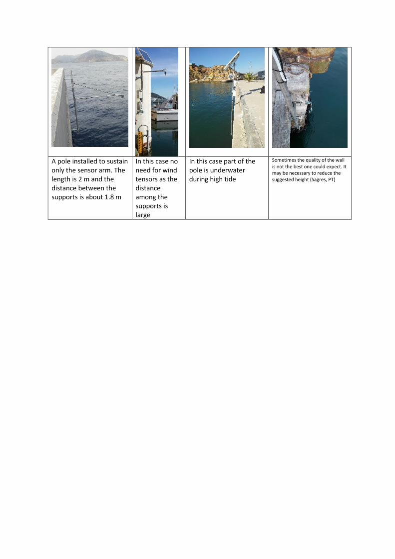
A pole installed to sustain only the sensor arm. The length is 2 m and the distance between the supports is about 1.8 m
In this case no need for wind tensors as the distance among the supports is large
In this case part of the pole is underwater during high tide
Sometimes the quality of the wall is not the best one could expect. It may be necessary to reduce the suggested height (Sagres, PT)
3 Power source installation
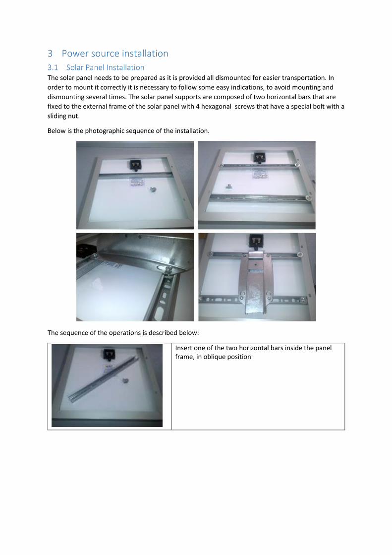
3.1 Solar Panel Installation The solar panel needs to be prepared as it is provided all dismounted for easier transportation. In
order to mount it correctly it is necessary to follow some easy indications, to avoid mounting and
dismounting several times. The solar panel supports are composed of two horizontal bars that are
fixed to the external frame of the solar panel with 4 hexagonal screws that have a special bolt with a
sliding nut.
Below is the photographic sequence of the installation.
The sequence of the operations is described below:
Insert one of the two horizontal bars inside the panel frame, in oblique position

Rotate the bar to go below the frame at ¼ of the total vertical length of the panel
Insert the bolt with the washer positioning the sliding nut inside the bars. Below a detail of the sliding nut. Be careful to position the nut in the direction of closing otherwise it will not fix
It is better not to fix completely the bar to have the possibility to a final adjustment
Repeat the same procedure with the other bar and keep a distance between the two bars approximately 50% of the length of the panel. Again do not fix the bars strongly
Position the structure to host the support for the pole between the two bars using similar sliding nuts and bolts. When all is well positioned you can fix firmly all the bolts.
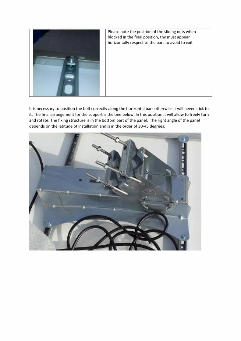
Please note the position of the sliding nuts when blocked in the final position, thy must appear horizontally respect to the bars to avoid to exit
It is necessary to position the bolt correctly along the horizontal bars otherwise it will never stick to
it. The final arrangement for the support is the one below. In this position it will allow to freely turn
and rotate. The fixing structure is in the bottom part of the panel. The right angle of the panel
depends on the latitude of installation and is in the order of 30-45 degrees.
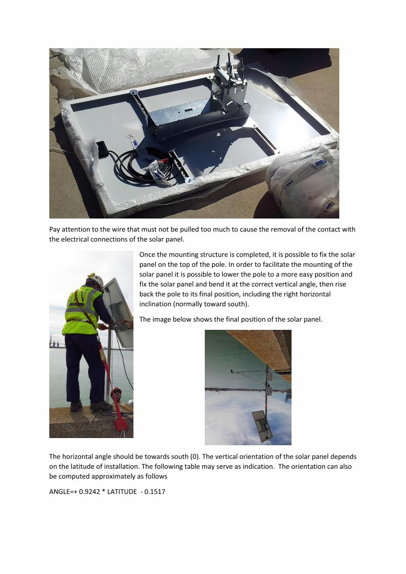
Pay attention to the wire that must not be pulled too much to cause the removal of the contact with
the electrical connections of the solar panel.
Once the mounting structure is completed, it is possible to fix the solar
panel on the top of the pole. In order to facilitate the mounting of the
solar panel it is possible to lower the pole to a more easy position and
fix the solar panel and bend it at the correct vertical angle, then rise
back the pole to its final position, including the right horizontal
inclination (normally toward south).
The image below shows the final position of the solar panel.
The horizontal angle should be towards south (0). The vertical orientation of the solar panel depends
on the latitude of installation. The following table may serve as indication. The orientation can also
be computed approximately as follows
ANGLE=+ 0.9242 * LATITUDE - 0.1517

Latutude Inst.
Angle
0 0
5 4.4
10 8.7
15 13.1
20 17.4
25 22.1
30 25.9
35 29.7
40 33.5
45 37.3
50 41.1
3.2 AC power source installation In case a local power source is available, an extension cable is provided (max length 50 m) in order to
decouple the sensor area from the AC power source area. An example is given below for the Cartagena
installation in which the AC power source was located in a box at about 40 m from the sensor location.
-5
0
5
10
15
20
25
30
35
40
45
0 10 20 30 40 50 60
Inst
alla
tio
n a
ngl
e (d
egre
e)
Latitude (degree)
Solar Panel Angle
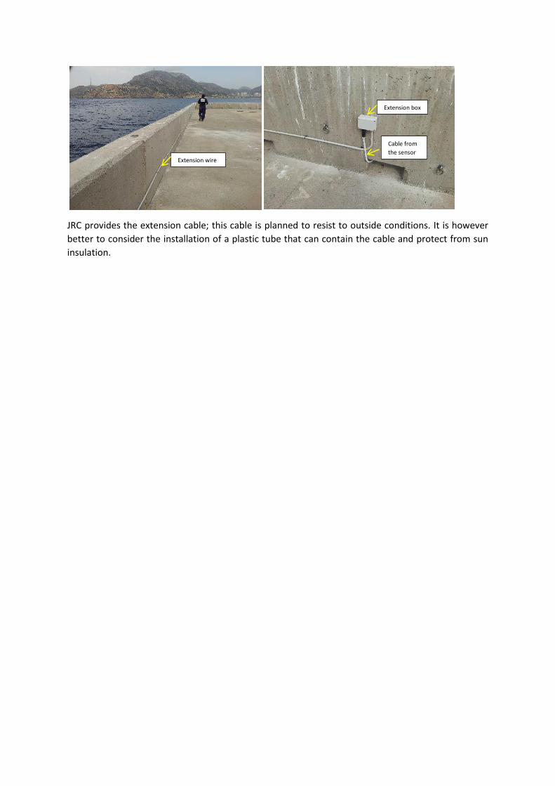
JRC provides the extension cable; this cable is planned to resist to outside conditions. It is however
better to consider the installation of a plastic tube that can contain the cable and protect from sun
insulation.
Extension box
Cable from
the sensor Extension wire
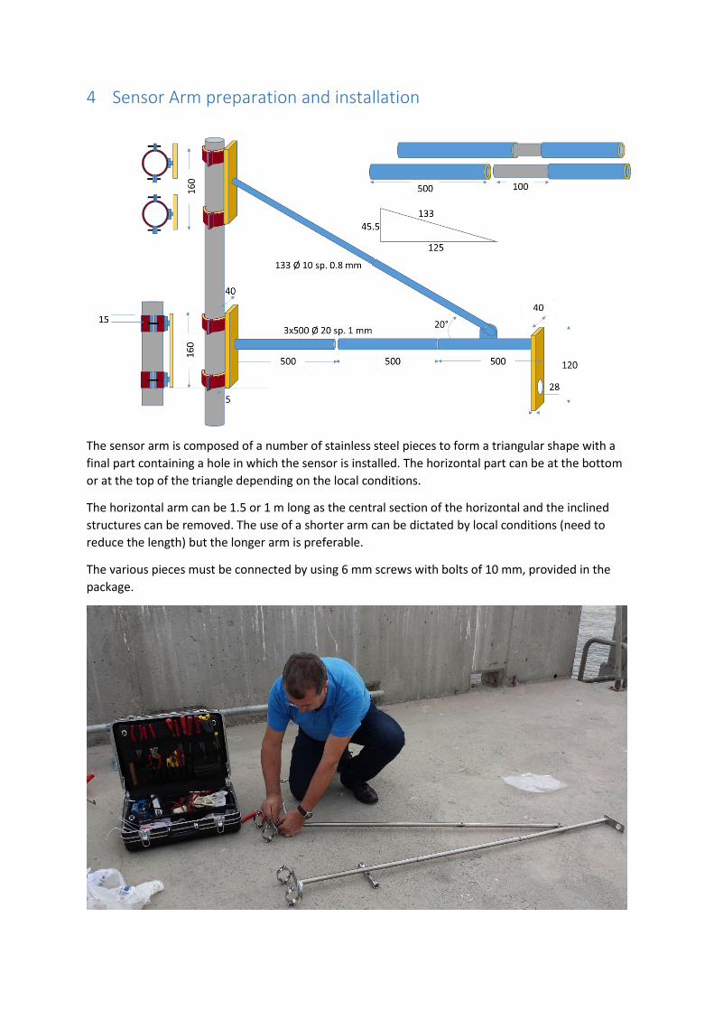
4 Sensor Arm preparation and installation
The sensor arm is composed of a number of stainless steel pieces to form a triangular shape with a
final part containing a hole in which the sensor is installed. The horizontal part can be at the bottom
or at the top of the triangle depending on the local conditions.
The horizontal arm can be 1.5 or 1 m long as the central section of the horizontal and the inclined
structures can be removed. The use of a shorter arm can be dictated by local conditions (need to
reduce the length) but the longer arm is preferable.
The various pieces must be connected by using 6 mm screws with bolts of 10 mm, provided in the
package.

Once the installation of the arm is performed, it can be fixed to the pole using the screws. At this
point it is possible to include the sensor and fix the sensor cable using 3 or 4 cable ties (or tie-wraps)
along the horizontal pipe.
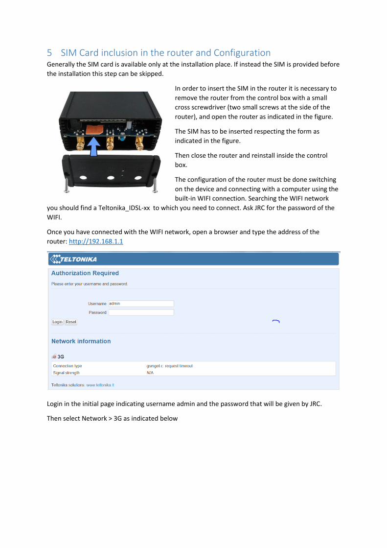
5 SIM Card inclusion in the router and Configuration Generally the SIM card is available only at the installation place. If instead the SIM is provided before
the installation this step can be skipped.
In order to insert the SIM in the router it is necessary to
remove the router from the control box with a small
cross screwdriver (two small screws at the side of the
router), and open the router as indicated in the figure.
The SIM has to be inserted respecting the form as
indicated in the figure.
Then close the router and reinstall inside the control
box.
The configuration of the router must be done switching
on the device and connecting with a computer using the
built-in WIFI connection. Searching the WIFI network
you should find a Teltonika_IDSL-xx to which you need to connect. Ask JRC for the password of the
WIFI.
Once you have connected with the WIFI network, open a browser and type the address of the
router: http://192.168.1.1
Login in the initial page indicating username admin and the password that will be given by JRC.
Then select Network > 3G as indicated below
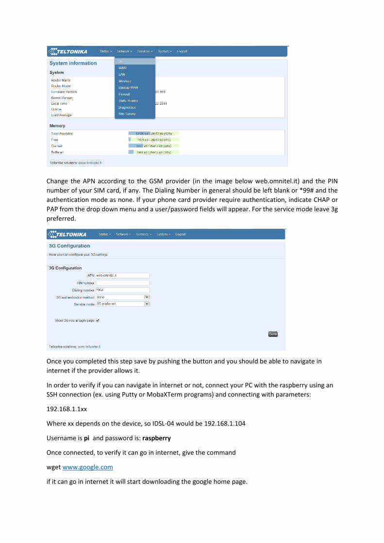
Change the APN according to the GSM provider (in the image below web.omnitel.it) and the PIN
number of your SIM card, if any. The Dialing Number in general should be left blank or *99# and the
authentication mode as none. If your phone card provider require authentication, indicate CHAP or
PAP from the drop down menu and a user/password fields will appear. For the service mode leave 3g
preferred.
Once you completed this step save by pushing the button and you should be able to navigate in
internet if the provider allows it.
In order to verify if you can navigate in internet or not, connect your PC with the raspberry using an
SSH connection (ex. using Putty or MobaXTerm programs) and connecting with parameters:
192.168.1.1xx
Where xx depends on the device, so IDSL-04 would be 192.168.1.104
Username is pi and password is: raspberry
Once connected, to verify it can go in internet, give the command
wget www.google.com
if it can go in internet it will start downloading the google home page.

6 Control and battery module installation
6.1 Control Module Installation After having inserted the SIM and verified that it can
go in internet, you can proceed by fixing the control
module on the pole. Take into account that in case
of extended flooding of this location, it is very
difficult that the module will survive if immersed in
water. Therefore you should install in a high position
on the pole.
The installation is quite simple, it is sufficient to un
screw the 4 screws behind the panel and fix firmly
the collars on the pole. Leave enough space below
the control panel to allow the cables insertion.
6.2 Battery Module installation The battery module should be installed below the
control module because, being much heavier it is
better not to have too much weight at higher levels.
6.3 AC power adapter installation If there is AC power available (and not solar panel),
the AC adapter will be positioned somewhere close
to the control module.
AC power adapter
Control module
Control module
Battery Pack
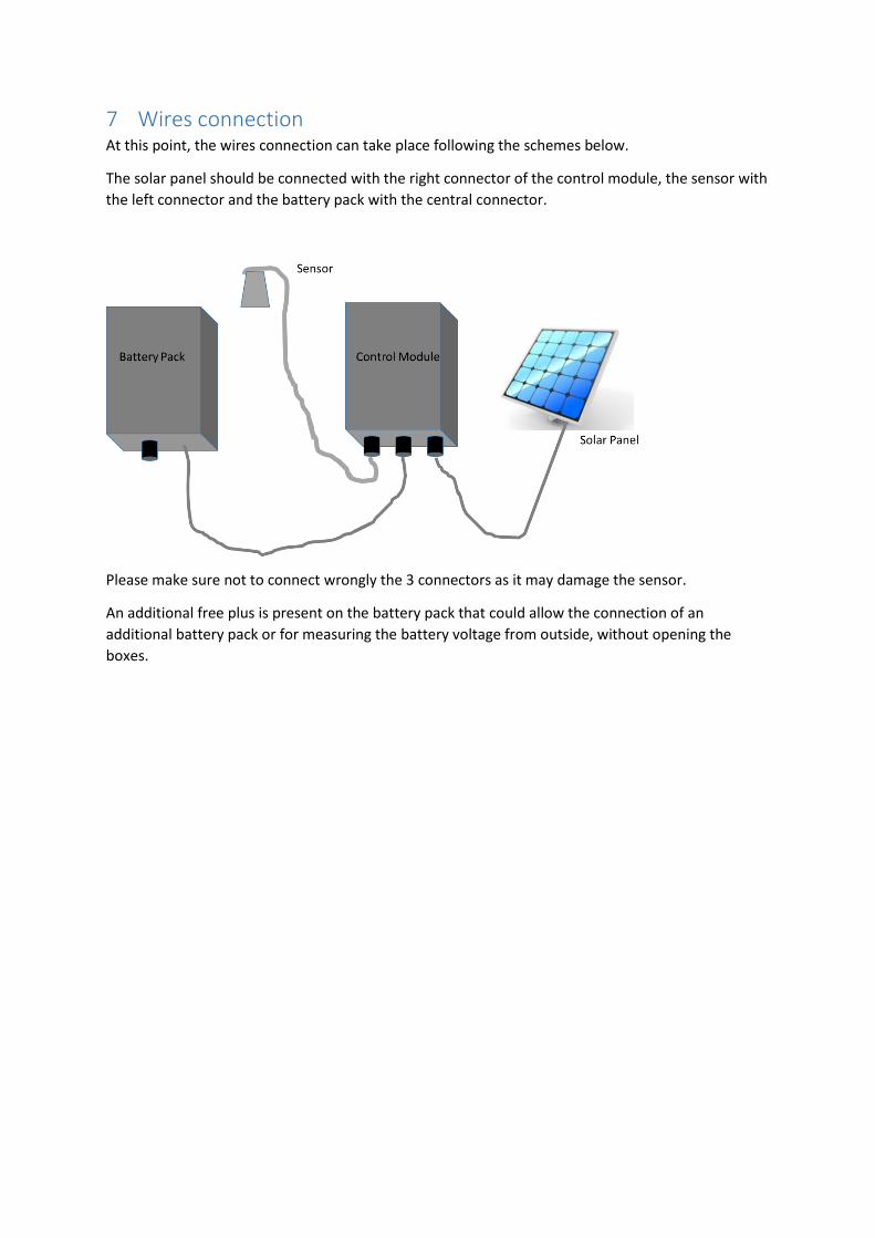
7 Wires connection At this point, the wires connection can take place following the schemes below.
The solar panel should be connected with the right connector of the control module, the sensor with
the left connector and the battery pack with the central connector.
Please make sure not to connect wrongly the 3 connectors as it may damage the sensor.
An additional free plus is present on the battery pack that could allow the connection of an
additional battery pack or for measuring the battery voltage from outside, without opening the
boxes.
8 Wind tension wires The installation of the wind tension wire is necessary when the panel exposes the pole to wind. In
some cases, when the distance between the pole support is very high or there is no solar panel,
there is not a strong need for these wires, however it can be judged on a case-by-case basis.
When wires are needed, there can be wires for the pole and wires for the arm. The wires are strong
stainless steel wires of about 1 mm diameter that are used by fixing a ring on the ground and
connecting them with the solar panel structure close to the pole. Tensors are used in order to have
the right tension to the pole.
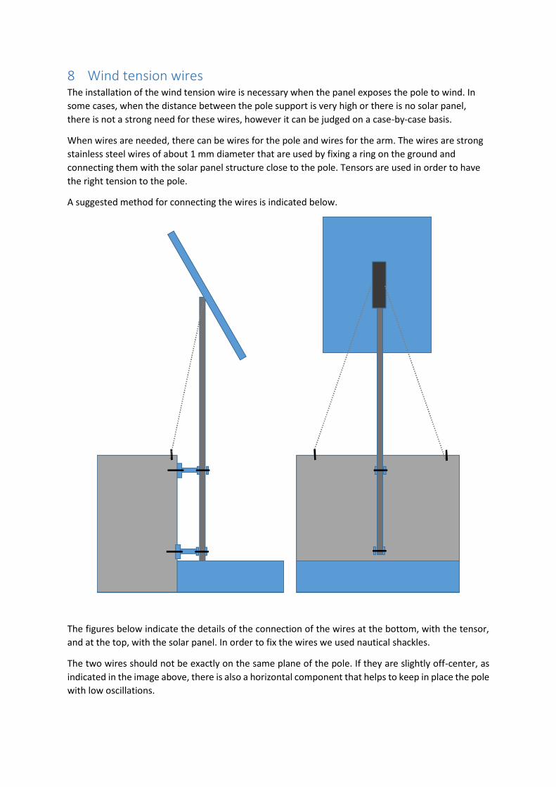
A suggested method for connecting the wires is indicated below.
The figures below indicate the details of the connection of the wires at the bottom, with the tensor,
and at the top, with the solar panel. In order to fix the wires we used nautical shackles.
The two wires should not be exactly on the same plane of the pole. If they are slightly off-center, as
indicated in the image above, there is also a horizontal component that helps to keep in place the pole
with low oscillations.

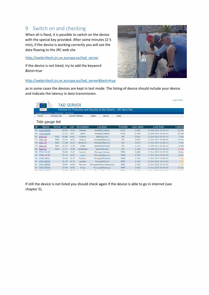
9 Switch on and checking When all is fixed, it is possible to switch on the device
with the special key provided. After some minutes (2-5
min), if the device is working correctly you will see the
data flowing to the JRC web site
http://webcritech.jrc.ec.europa.eu/tad_server
if the device is not listed, try to add the keyword
&test=true
http://webcritech.jrc.ec.europa.eu/tad_server&test=true
as in some cases the devices are kept in test mode. The listing of device should include your device
and indicate the latency in data transmission.
If still the device is not listed you should check again if the device is able to go in internet (see
chapter 5).

9.1 How to switch off and on the Control Panel
Identify the key switch on the right side of the bottom of the control panel
Note the small tooth on the switch key
Insert the key in horizontal position (respect to the box length)
OFF
ON
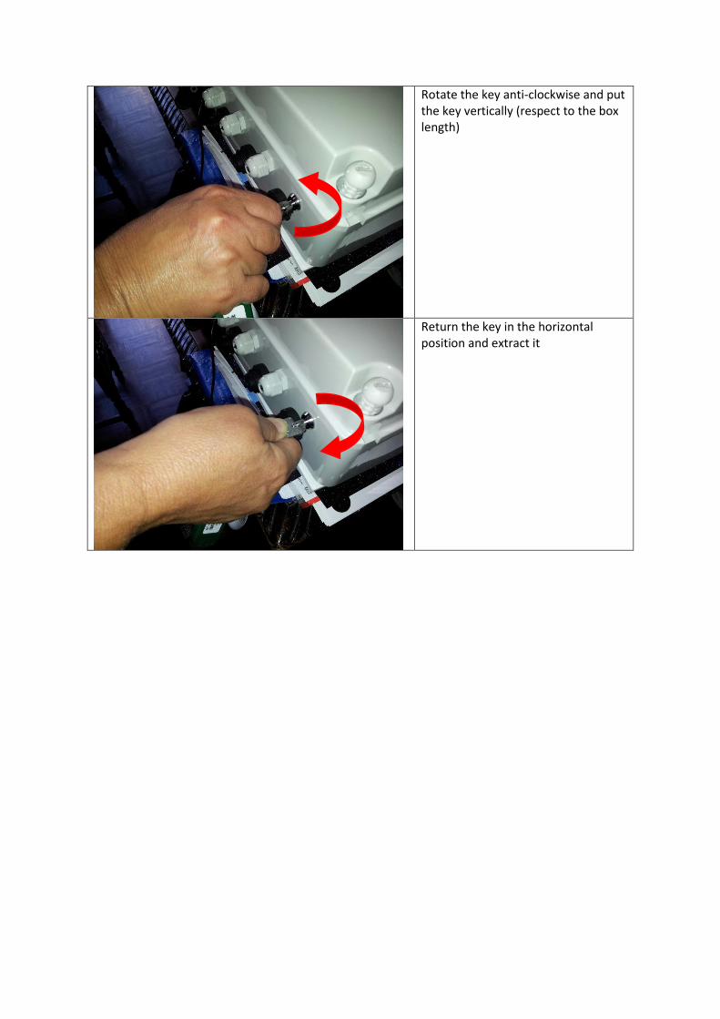
Rotate the key anti-clockwise and put the key vertically (respect to the box length)
Return the key in the horizontal position and extract it

10 Lessons Learnt from the Installations In this chapter we try to indicate the lessons learnt from the installations performed so far that can
be useful for new installation. As every installation is a new case, this chapter will evolve all the
times.
1. (WHO IS INSTALLING) Use a rope to keep material and tools and avoid falling under water:
anything on the sea must be secured (included the persons)
2. (LOCAL SUPPORT PERSONNEL) Bring all the appropriate tools and in particular
a. Driller with the series of Drill Bits, including the large ones for the chemical anchors
b. Chemical anchors glue
c. Allen key for the solar panels
d. Mechanical keys and at least numbers 7, 10, 13, 17
e. Angle grinder for cutting pieces
f. Electrical power source, either with wire or autonomous
g. Cutter
h. Several cable ties of various dimensions
i. Hammer
j. Pliers
3. Ensure that the support unit onsite has the right equipment for descending on the vertical
wall
4. (JRC Personnel) Be sure to have replacement parts for:
a. All screws, bolts, sliding nuts
b. Router, Raspberry, power regulator or alternatively, if possible, one complete
control box