Embed Size (px)
Citation preview

Grid-Interop Forum 2011
IDENTIFYING ARCHITECTURAL MODULARITY IN THE SMART GRID: AN APPLICATION OF DESIGN STRUCTURE MATRIX METHODOLOGY
Brad Rogers Erik Gilbert
Navigant Consulting 1375 Walnut Street, Suite 200
Boulder, CO 80302
KEYWORDS: architecture, modularity, design structure matrix, complexity, accidental architecture
ABSTRACT
This paper demonstrates a vetted methodology for identifying areas of architectural modularity using two detailed architecture references:
NISTIR Logical Reference Model [1] – a work product of the NIST smart grid standards effort that establishes actors and interfaces in the smart grid
NRECA’s Demonstration Architecture [2] – a planned architecture for a federally funded smart grid demonstration project.
The design structure matrix methodology [3] is applied with the intent to demonstrate how this approach can apply to defining smart grid architectures and to help identify architectural groupings that can lead to better modularization of smart grid systems and standards efforts. This paper is intended to inform current and future smart grid architecture efforts and to help improve the organization by which smart grid systems and standards can be established. The paper concludes that initial smart grid architectural efforts (as documented in [1] and [2], actual architectures may have other constraints such as backward compatibility) can be improved upon by identifying areas of modularity and organizing around them. The tools demonstrated can be best applied when the full dimensionality and scope of the problem is made explicit, but the demonstrations in this paper that use only publically available information also yield interesting findings.
1. WHY MODULARITY? One significant interoperability challenge today is to integrate with legacy systems while driving toward elegant solutions for future integrations. This challenge is compounded by a phenomenon called “accidental architecture.” [4]
An accidental architecture is the de facto structure of a system resulting from numerous point-to-point integrations between various applications to achieve near-term objectives. Point-to-point integrations are not scalable and often create unintended ripple effects on downstream applications. The result of this haphazard evolution is a unique and customized system that becomes increasingly difficult to maintain, update and integrate with. Minimizing the accidental architecture phenomenon requires both backward-looking and forward-looking efforts – how do we integrate with the existing architectures of today while ensuring robust architectures tomorrow.
Part of the mechanism that leads to accidental architectures is the highly integrated nature of these grid communication systems. The characteristics of each dependency and interface of the system are so nuanced that custom approaches are required. The original architectural principals of these systems can be difficult and costly to maintain, and therefore they are not maintained.
Modular systems [5], on the other hand, are less tightly integrated and tend to integrate easily, evolve flexibly, and operate simply and reliably [6]. Modularity can often be difficult to achieve in large complex systems. This paper demonstrates a vetted approach to identifying modularity in complex systems that can lead to improved system structures and ultimately reduce the impetus for point-to-point integrations that lead to accidental architectures.

Rogers & Gilbert
Grid-Interop Forum 2011
2. DESIGN STRUCTURE MATRIX OVERVIEW The design structure matrix (DSM) is a modeling tool that represents the relationships and dependencies between components of a system, product, or process. The DSM was first introduced by Donald Steward [7] and captures coupling and dependency relationships between the components of a system.
The DSM methodology has been applied to understand and improve the architecture of complex products and processes in automotive [8], aerospace [9], and other technology-based industries – including architecture for meter data management systems. [10] The matrix format is a useful visualization tool that cleanly represents dependencies between elements within systems, simplifying the study and analysis of systems. The matrix format allows systematic application of a variety of quantitative techniques – such as clustering described below – that can be used to characterize [11] and organize [12] complex systems. The DSM methodology has also been extensively applied to the study of process architectures [13] in addition to system architectures. The DSM represents the components of a system as rows and columns in a matrix where the components are listed in
the same order along both axes. An off-diagonal mark located within the matrix denotes an interface, dependence or coupling between two components. The diagonal of the square matrix is unimportant and often shaded a different color since the DSM analysis only looks at relationships across components and not within components. Steward’s original model is also referred to as a binary DSM because each cell in the matrix represents a binary choice of
dependency. For example, the system shown in Figure 1, where each subsystem is represented by a letter, can be represented as a 7x7 binary DSM. The example shown here is a symmetric structure where each coupling shows interdependency (bi-directional) rather than hierarchical dependency (uni-directional), which is typical in architectures of physical systems. Note: Processes are a typical example where hierarchical dependency occurs where one task must be completed before another task can begin. For this reason, process DSM representations are typically asymmetric. Clustering is a process applied to a DSM by which subsystems are arranged and grouped in order to minimize interdependency across groups. Groupings may be called architectural areas or subsystems, which are defined simply as groups whose internal elements exhibit relatively high dependency, and whose external elements exhibit relatively
Figure 1. Simple Example System and DSM Representation
Figure 2. Example System DSM Clustered into More Modular Subsystems

Rogers & Gilbert
Grid-Interop Forum 2011
low dependency. Interfaces between subsystems require individual attention, but the process of clustering is intended to minimize the number of subsystem interfaces. Clustering is an organizational optimization process that is intended to assist in identifying useful architectures by rearranging the order of the components in the rows and columns of the matrix as shown in Figure 2. The paper later develops a DSM for the smart grid based on the NIST Logical Reference Model and NRECA’s Demonstration Architecture and processes the corresponding DSMs based on a clustering algorithm [14] to identify groupings that may lead to an improved smart grid architecture and standards development organization.
3. SMART GRID ARCHITECTURE REFERENCES The DSM methodology requires identification of components of a system, as well as the dependencies or interfaces between the components as a starting point. The analysis performed here does not identify new components or dependencies in the smart grid, but instead uses components and dependencies identified in existing smart grid references. Two smart grid architectural references are widely accepted – the GWAC Stack [15,16] and the NIST Conceptual Model. [17] These are very useful architectural references, but do not provide sufficient detail on the underlying components of the smart grid and the dependencies between them to apply the DSM methodology. Two other architectural references, however, do provide a level of detail for which the DSM methodology could be useful – the NISTIR Logical Reference Model and NRECA’s Demonstration Architecture. This section describes each of these four architecture references.
3.1. GWAC Stack The GridWise Context-Setting Framework identifies communications layers as a key dimension of the smart grid architecture. The communications layers proposed by the GridWise Architecture Council are colloquially referred to as the “GWAC Stack,” which is shown in Figure 3. As a framework, the GWAC Stack makes no architectural or technical recommendations but establishes a context to discuss alternatives and complementary approaches. It is a high-level, operational view common to the electricity community used to communicate within the electricity system to compare, align, and harmonize solutions and processes as well as to manage critical infrastructure.
Figure 3. The GWAC Stack Interoperability Framework
3.2. NIST Conceptual Model The NIST Conceptual Model is intended as a high-level, overarching perspective tool for identifying actors, communications paths, interactions, applications, and capabilities enabled by these interactions. The Conceptual Model is intended to aid in analysis – it is not a design diagram that defines a solution and its implementation. In other words, the conceptual model is descriptive and not prescriptive. It is meant to foster understanding of Smart Grid operational intricacies but not prescribe how the smart grid will be implemented. Figure 4. NIST Smart Grid Conceptual Model: Domains and Customer Domain Detail
It does not represent the final architecture of the smart grid, rather it is a tool for describing, discussing, and developing that architecture. The conceptual model provides a context for analysis of interoperation and standards for the development of the architectures of the smart grid. The top level domains of the conceptual model and a detail of the customer domain are shown in Figure 4.
Domains Customer Domain Detail

Rogers & Gilbert
Grid-Interop Forum 2011
Figure 5 depicts a refinement of the conceptual model meant to combine the domain views into one diagram and includes example actor names, organizational structure, communications networks and some information about security concerns. Figure 5. NIST Combined Conceptual Reference Diagram
However, neither of the NIST Conceptual Model illustrations is intended to provide a complete list of smart grid components and their dependencies.
3.3. Logical Reference Model The Guidelines for Smart Grid Cyber Security: Vol. 1, Smart Grid Cyber Security Strategy, Architecture, and High-Level Requirements is a document produced by the Smart Grid Interoperability Panel, Cyber Security working group. The document expands upon the NIST Conceptual Model to depict a composite high-level view of the actors within each of the smart grid domains and the logical interfaces between them – the Logical Reference Model shown in Figure 6. Although cyber security is the primary purpose of the document, the Logical Reference Model provides sufficient detail for use as an input in DSM methodology. This diagram served as the basis for the first DSM analysis.
3.4. NRECA’s Demonstration Architecture The National Rural Electric Cooperative Association (NRECA) developed a detailed architecture as part of an Interoperability and Cyber Security Plan required by the DOE for a smart grid demonstration project partially funded through an ARRA grant. The Demonstration Architecture is based on the NIST Conceptual Model, but has been modified to sufficiently meet the specific needs of this project. In addition to identifying the key components that must interoperate, the NRECA document also identifies
Figure 6. Actors and Interfaces Identified in the Logical Reference Model

Rogers & Gilbert
Grid-Interop Forum 2011
each expected interface between the components. The level of detail provided in NRECA’s architecture is sufficient for use as an input to the DSM methodology. Although this architecture is specific to the demonstration project and may not encompass every possible facet of the future smart grid, this architecture may be the most advanced to date coming from an actual smart grid implementation project. The diagram show in Figure 7 and its documentation served as the basis for the second DSM analysis. The following sections discuss the application of the DSM methodology in the context of the NISTIR Logical Reference Model and NRECA’s Demonstration Architecture.
4. APPLICATION OF DSM TO THE LOGICAL REFERENCE MODEL
The Logical Reference Model was chosen for further analysis since it portrays the structure of the smart grid in greater detail and fidelity than the NIST Conceptual Model and the GWAC Stack. The Logical Reference Model identifies 48 actors and the interfaces between them as shown in Figure 6. The interfaces were further grouped into 22 categories; however, this paper does not qualify each interface by category, but rather treats the interfaces in a binary fashion.
These actors and interfaces were transformed into a DSM representation with the actors listed along the rows and columns in the order that they are numbered by the Logical Reference Model. The resulting DSM is depicted in Figure 8. Although there does appear to be some cluster density in the initial organization of Logical Reference Model (actors 2-11, which portray the customer domain), actors outside of the customer domain do not appear to be optimally organized since their interfaces are sparsely distributed throughout the matrix. If a more optimal organization and grouping of actors is possible, this should be evident after arranging and optimizing the DSM for clusters. A clustering exercise was performed to identify modular groups. Two similar schemes emerged from the clustering exercise, shown in Figure 9 and Figure 10.
Figure 7. NRECA's Demonstration Architecture: Physical and Logical Architecture for Enterprise Application Integration

Roge
rs &
Gilb
ert
Gri
d-In
tero
p Fo
rum
201
1
Fi
gure
8. D
SM R
epre
sent
atio
n of
the
NIS
TIR
Log
ical
Ref
eren
ce M
odel
(gro
uped
acc
ordi
ng to
Con
cept
ual M
odel
Dom
ains
)

Roge
rs &
Gilb
ert
Gri
d-In
tero
p Fo
rum
201
1
Figu
re 9
. Clu
ster
ed D
SM R
epre
sent
atio
n of
the
NIS
TIR
Log
ical
Ref
eren
ce M
odel
– S
chem
e 1

Roge
rs &
Gilb
ert
Gri
d-In
tero
p Fo
rum
201
1
Figu
re 1
0. C
lust
ered
DSM
Rep
rese
ntat
ion
of th
e N
IST
IR L
ogic
al R
efer
ence
Mod
el –
Sch
eme
2
Rogers & Gilbert
Grid-Interop Forum 2011
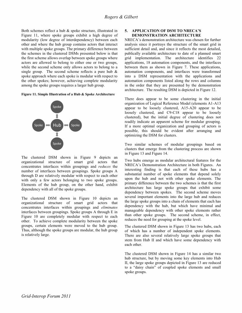
Both schemes reflect a hub & spoke structure, illustrated in Figure 11, where spoke groups exhibit a high degree of modularity (low degree of interdependency) between each other and where the hub group contains actors that interact with multiple spoke groups. The primary difference between the schemes in the clustered DSMs presented below is that the first scheme allows overlap between spoke groups where actors are allowed to belong to either one or two groups, while the second scheme only allows actors to belong to a single group. The second scheme reflects a pure hub & spoke approach where each spoke is modular with respect to the other spokes; however, achieving complete modularity among the spoke groups requires a larger hub group. Figure 11. Simple Illustration of a Hub & Spoke Architecture
The clustered DSM shown in Figure 9 depicts an organizational structure of smart grid actors that concentrates interfaces within groupings and reduces the number of interfaces between groupings. Spoke groups A through D are relatively modular with respect to each other with only a few actors belonging to two spoke groups. Elements of the hub group, on the other hand, exhibit dependency with all of the spoke groups. The clustered DSM shown in Figure 10 depicts an organizational structure of smart grid actors that concentrates interfaces within groupings and eliminates interfaces between groupings. Spoke groups A through E in Figure 10 are completely modular with respect to each other. To achieve complete modularity between the spoke groups, certain elements were moved to the hub group. Thus, although the spoke groups are modular, the hub group is relatively large.
5. APPLICATION OF DSM TO NRECA’S DEMONSTRATION ARCHITECTURE
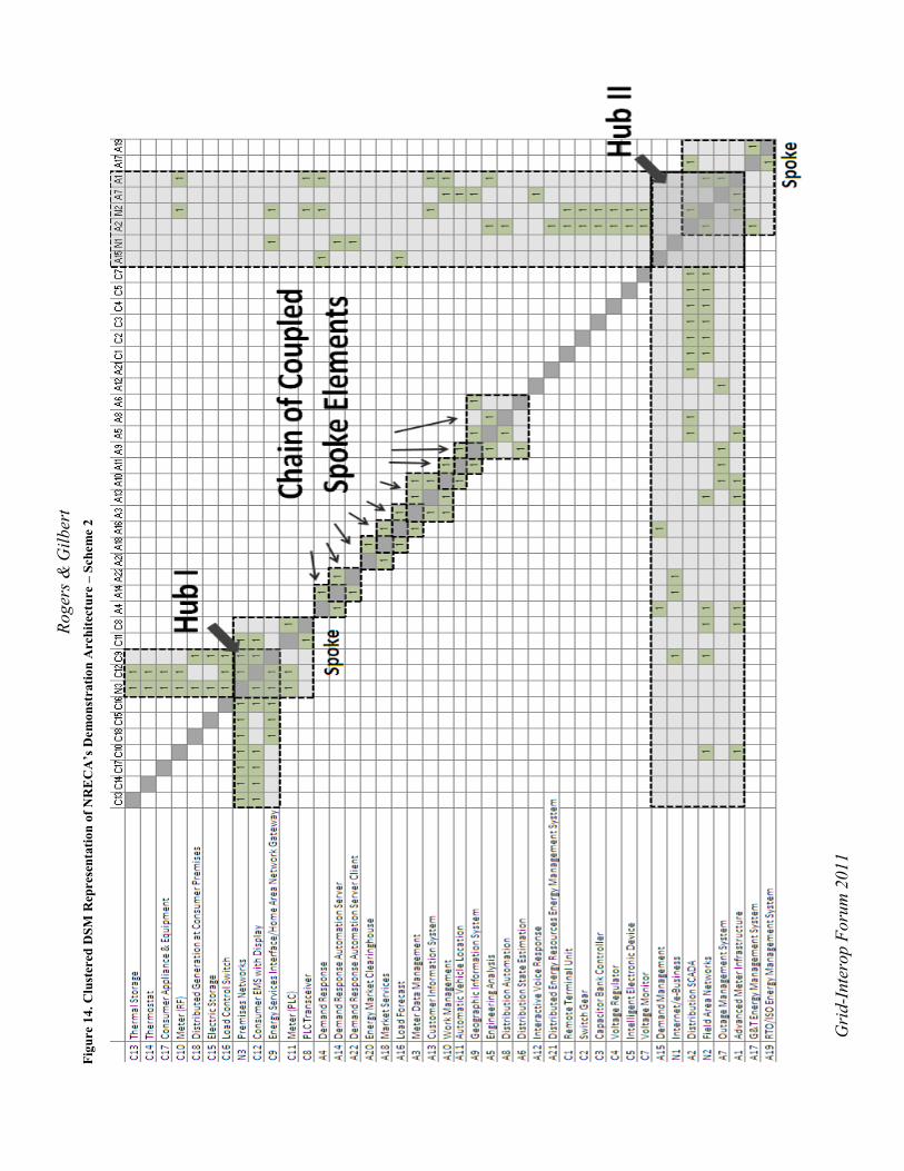
NRECA’s demonstration architecture was chosen for further analysis since it portrays the structure of the smart grid in sufficient detail and, and since it reflects the most detailed, publically available architecture to date of a planned smart grid implementation. The architecture identifies 22 applications, 18 automation components, and the interfaces between them as shown in Figure 7. These applications, automation components, and interfaces were transformed into a DSM representation with the applications and automation components listed along the rows and columns in the order that they are presented by the demonstration architecture. The resulting DSM is depicted in Figure 12. There does appear to be some clustering in the initial organization of Logical Reference Model (elements A1-A13 appear to be loosely clustered, A15-A20 appear to be loosely clustered, and C9-C18 appear to be loosely clustered), but the initial degree of clustering does not readily indicate an apparent scheme for modular grouping. If a more optimal organization and grouping of actors is possible, this should be evident after arranging and optimizing the DSM for clusters. Two similar schemes of modular groupings based on clusters that emerge from the clustering process are shown in Figure 13 and Figure 14.
Two hubs emerge as modular architectural features for the NRECA’s Demonstration Architecture in both Figures. An interesting finding is that each of these hubs has a substantial number of spoke elements that depend solely upon the hub and not with other spoke elements. The primary difference between the two schemes is that the first architecture has large spoke groups that exhibit some dependency between spokes. The second scheme moves several important elements into the large hub and reduces the large spoke groups into a chain of elements that each has dependency with the hub, but which have minimal and manageable dependency with other spoke elements rather than other spoke groups. The second scheme, in effect, reduces the need for grouping at the spoke level.
The clustered DSM shown in Figure 13 has two hubs, each of which has a number of independent spoke elements. There are also several relatively large spoke groups that stem from Hub II and which have some dependency with each other. The clustered DSM shown in Figure 14 has a similar two hub structure, but by moving some key elements into Hub II, the large spoke groups depicted in Figure 13 are reduced to a “daisy chain” of coupled spoke elements and small spoke groups.
Hub
Spoke
Spoke
Spoke
Spoke

Roge
rs &
Gilb
ert
Gri
d-In
tero
p Fo
rum
201
1
Figu
re 1
2. D
SM R
epre
sent
atio
n of
NR
EC
A's
Dem
onst
ratio
n A
rchi
tect
ure

Roge
rs &
Gilb
ert
Gri
d-In
tero
p Fo
rum
201
1
Figu
re 1
3. C
lust
ered
DSM
Rep
rese
ntat
ion
of N
RE
CA
’s D
emon
stra
tion
Arc
hite
ctur
e –
Sche
me
1
Roge
rs &
Gilb
ert
Gri
d-In
tero
p Fo
rum
201
1
Figu
re 1
4. C
lust
ered
DSM
Rep
rese
ntat
ion
of N
RE
CA
’s D
emon
stra
tion
Arc
hite
ctur
e –
Sche
me
2

Rogers & Gilbert
Grid-Interop Forum 2011
6. CONCLUSIONS Two smart grid reference architectures – the NISTIR Logical Reference Architecture and NRECA’s Demonstration Architecture – were analyzed using the design structure matrix (DSM) methodology. Visual comparison of the DSM for each architecture before and after clustering indicates that there is room for improvement in identifying and organizing by areas of modularity. A “hub & spoke” scheme for grouping architectural elements emerges from clustering the DSMs representing both reference architectures. Spokes are groupings of elements that exhibit a high degree of dependency with each other and minimal dependency with elements of other spokes. Hubs are groupings of elements that exhibit a high degree of dependency with elements of multiple spoke elements. Clustering allows identification of groupings that are meant to simplify architectures by creating areas of modularity and identifying critical elements that are integral to the system. It is in fact the identification and grouping of these cross-cutting elements in the system that allows for modularity to be identified elsewhere in the system. Prioritizing these hub elements and acknowledging their importance can reduce the complexity of the system and can even be used to create hierarchical protocols. Modularization can help combat accidental architectures by isolating groups of dependency allowing them to be treated as quasi-independent sub-systems. Modular systems can evolve more elegantly because modular organization is more easily respected than highly integrated systems when upgrades or additions are needed. Identifying modularization can also be useful for setting smart grid standards. Hub elements can be viewed as elements which provide the architectural foundation and can be prioritized. Standards for spoke elements if developed in coordination with their respective hub elements would then not require substantial harmonization or iteration with other spoke groups. Inadequate architectural organization does not create modularity, but instead leads to highly integrated systems that cannot integrate easily, evolve flexibly, and operate simply and reliably. The approach demonstrated here can be applied to study existing utility architectures and to identify appropriate technical solutions going forward.
REFERENCES
[1] NISTIR 7628. “Guidelines for Smart Grid Cyber Security.” v1.0, Volume 1, p. 17. Aug 2010.
[2] “Interoperability and Cyber Security Plan, NRECA CRN Smart Grid Regional Demonstration.” May 2010.
[3] http://www.dsmweb.org/
[4] Giroti, Tony. “Integration Roadmap for Smart Grid: From Accidental Architecture to Smart Grid Architecture.” 2009.
[5] Schilling, M.A. 2000. Towards a general modular systems theory and its application to inter-firm product modularity. Academy of Management Review, Vol 25:312–334.
[6] Crowley, E. 2007. Introduction to System Architecture. Rev 2. Massachusetts Institute of Technology. Open CourseWare.
[7] Steward, Donald V., “Systems Analysis and Management: Structure, Strategy and Design,” Petrocelli Books, Princeton, NJ, 1981. [8] Eppinger, S.D. “A Planning Method for Integration of Large-Scale Engineering Systems.” ICED 97 Tampere, Aug.19.
[9] Tripathy, A., Eppinger, S.D. “System Architecture Approach to Global Product Development” MIT 2007, Working Paper No. 4645-07.
[10] Prasannan, S. “A Macro-Micro System Architecture Analysis Framework Applied to Smart Grid Meter Data Management Systems.” MIT 2010.
[11] MacCormack, A., et. al. “Exploring the Structure of Complex Software Designs: An Empirical Study of Open Source and Proprietary Code.” Management Science, Vol. 52, No. 7, July 2006, p. 1015-1030. (Characterizes and compares modularity in the architectures of Mozzilla and Linux.)
[12] Browning, T. “Applying the Design Structure Matrix to System Decomposition and Integration Problems: A Review and New Directions.” IEEE Transactions on Engineering Management, Vol. 48, No 3, August 2001, p.292-306.
[13] Rogers, B. “Understanding, Modeling and Improving the Development of Complex Products: Method and Study.” MIT 2009.
[14] Knowledge Management of System Interfaces and Interactions for Product Development Processes, Ronnie Thebeau, MIT February 2001.

Rogers & Gilbert
Grid-Interop Forum 2011
[15] “GridWise Interoperability Context-Setting Framework.” The GridWise Architecture Council, March 2008. p5
[16] The GridWise Interoperability Context-Setting Framework is a work of the GridWise Architecture Council.
[17] “NIST Framework and Roadmap for Smart Grid Interoperability Standards Release 1.0,” Office of the National Coordinator for Smart Grid Interoperability, NIST (September 2009).
BIOGRAPHY
Brad Rogers, MS, MBA, is a Managing Consultant with Navigant's Energy Practice. He has most recently focused on smart grid economic assessment and interoperability issues. He has contributed to numerous efficiency and demand response program evaluation efforts by providing statistics expertise,
conducting technical interviews, and managing evaluation tasks.
Brad has quantitative expertise in the fields of optimization, Monte Carlo simulation, system dynamics, statistics, risk analysis, and decision analysis. He has applied these skills to the economic and technical assessment of energy technologies, to the improvement of product development processes, and to project management practices in the energy and aerospace industries. He has a working knowledge of renewable energy sources, nuclear technology, transmission, distribution, end-use efficiency and issues pertaining to smart grid.
Brad earned an MBA and an MS in Engineering Systems concentrated in Energy and Sustainability at the Massachusetts Institute of Technology.
Brad works out of the Boulder, Colorado office.
Erik Gilbert is an Associate Director with Navigant’s Energy Practice. His focus is on smart grid and demand response program analysis and technology strategy, including cost-benefit assessment. Mr. Gilbert has over twenty years of experience in developing and managing complex
products and market programs as well as performing program evaluations and assessments.
Prior to joining Navigant, Mr. Gilbert served as Director of smart-energy products for residential energy management system vendor Tendril Networks, Inc., where he defined and
executed their hardware roadmap, including in-home energy displays, IP-to-HAN gateways, AMR/ERT-to-ZigBee bridges and other products.
Previously, Mr. Gilbert held various management positions at Internet infrastructure provider Cisco Systems, Inc., as well as several years of technology strategy development with Ernst & Young Management Consulting. Mr. Gilbert began his career as a design engineer. He holds BS in Electrical Engineering and Computer Science from the Massachusetts Institute of Technology and an MBA from the University of California at Berkeley.