Embed Size (px)
Citation preview

MANUAL
finalconfidential2008-09-23H60100-5e-ID-B.doc
OBID® classic-pro
ID CPR.03.20-CDMultitag Reader Data-/Clock and RS232-TTL
up from firmware version 02.00.00

OBID® classic-pro Manual ID CPR.03.20-CD
FEIG ELECTRONIC GmbH Page 2 of 40 H60100-5e-ID-B.doc
Note
© Copyright 2007 byFEIG ELECTRONIC GmbHLange Strasse 4D-35781 Weilburg (Germany)Tel.: +49 6471 3109-0http://www.feig.de
With the edition of this manual, all previous editions become void. Indications made in this manual may bechanged without previous notice.
Copying of this document, and giving it to others and the use or communication of the contents thereof areforbidden without express authority. Offenders are liable to the payment of damages. All rights are reservedin the event of the grant of a patent or the registration of a utility model or design.
Composition of the information in this document has been done to the best of our knowledge. FEIGELECTRONIC GmbH does not guarantee the correctness and completeness of the details given in thismanual and may not be held liable for damages ensuing from incorrect or incomplete information. Since,despite all our efforts, errors may not be completely avoided, we are always grateful for your useful tips.
The instructions given in this manual are based on advantageous boundary conditions. FEIG ELECTRONICGmbH does not give any guarantee promise for perfect function in cross environments and does not giveany guaranty for the functionality of the complete system which incorporates the subject of this document.
FEIG ELECTRONIC call explicit attention that devices which are subject of this document are not designedwith components and testing methods for a level of reliability suitable for use in or in connection with surgicalimplants or as critical components in any life support systems whose failure to perform can reasonably beexpected to cause significant injury to a human. To avoid damage, injury, or death, the user or applicationdesigner must take reasonably prudent steps to protect against system failures.
FEIG ELECTRONIC GmbH assumes no responsibility for the use of any information contained in this docu-ment and makes no representation that they free of patent infringement. FEIG ELECTRONIC GmbH doesnot convey any license under its patent rights nor the rights of others.
OBID® and OBID i-scan® is a registered trademark of FEIG ELECTRONIC GmbH.I-CODE® and mifare® is a registered trademark of NXP (formerly Philips Electronics N.V.)my-d® is a registered trademark of Infineon Technologies AGTag-itTM is a registered trademark of Texas Instruments IncorporatedMicrosoft® and Windows® are registered trademarks of the Microsoft Corporation.
General information's regarding this manual
• If bits within one byte are filled with '-', these bit spaces are reserved for future extensions or for internaltesting- and manufacturing-functions. These bit spaces must not be changed, as this may cause faultyoperation of the Reader.
• The following figure formats are used:0...9: for decimal figures0x00...0xFF: for hexadecimal figures,b0...1 for binary figures.
OBID® classic-pro Manual ID CPR.03.20-CD
FEIG ELECTRONIC GmbH Page 3 of 40 H60100-5e-ID-B.doc
Content
1. Introduction 5
1.1. Optional Accessory.............................................................................................................5
2. Technical Specifications 6
2.1. Dimensions ..........................................................................................................................7
2.2. Applicable Standards..........................................................................................................8
2.3. Approval...............................................................................................................................8
2.4. UID Format ...........................................................................................................................9
3. Installation 10
3.1. Mounting ............................................................................................................................10
3.2. Connection.........................................................................................................................11
3.3. Configuration Procedure ..................................................................................................12
3.3.1. Default Configuration ...................................................................................................12
3.3.2. Reloading the configuration .........................................................................................12
4. Normal Operating Mode Fehler! Textmarke nicht definiert.
4.1. Digital Inputs......................................................................................................................14
4.2. Wiegand Interface .............................................................................................................15
4.2.1. UID...............................................................................................................................16
4.2.2. DATA-BLOCK..............................................................................................................16
4.3. Magstripe Track II Interface..............................................................................................17
4.3.1. UID...............................................................................................................................19
4.3.2. DATA-BLOCK..............................................................................................................19
4.4. Asynchronous Interface: RS232-TTL ..............................................................................20
4.4.1. UID...............................................................................................................................21
4.4.2. DATA-BLOCK..............................................................................................................21

OBID® classic-pro Manual ID CPR.03.20-CD
FEIG ELECTRONIC GmbH Page 4 of 40 H60100-5e-ID-B.doc
5. Reader Configuration - ConfigCard 22
5.1. Configuration Parameter (ConfigData)............................................................................22
5.2. ConfigCard - Data Structure.............................................................................................26
5.2.1. CRC16 Calculation Algorithm......................................................................................27
6. FEConfCardTool 28
6.1. Installation of FEConfiCardTool ......................................................................................28
6.2. Starting FEConfigCardTool ..............................................................................................29
6.3. FEConfigCardTool Functions ..........................................................................................30
7. Firmware update 32
7.1. Required components ......................................................................................................32
7.2. Programming .....................................................................................................................32
7.2.1. Starting and setting up HyperTerminal ........................................................................33
7.2.2. Reader synchronisation 'PPPPPPPP...'..................................................................34
7.2.3. Programming the firmware 'FLASHALL' command ................................................35
7.2.4. Verifying the firmware 'VERIFY' command .............................................................37
7.2.5. Exiting the Bootloader 'RESET' command..............................................................37
ANNEX 38
ANNEX A: Revision History of Documentation ......................................................................38
ANNEX B: Index of Status Bytes .............................................................................................39
ANNEX C: Memory Organization of Supported Transponders.............................................40

OBID® classic-pro Manual ID CPR.03.20-CD
FEIG ELECTRONIC GmbH Page 5 of 40 H60100-5e-ID-B.doc
1. Introduction
The Multitag Reader ID CPR.03.20-CD is designed for access control and time-recording systems.Via the configurable data-/clock interface it can connected easily with usual access control andtime-recording controllers. Also available for data output is a RS232-TTL interface.
The data-/clock interface can be configured like Wiegand- or Magnetic Stripe format (ISO7811-2,5 Bit).
The ID CPR.03.20-CD can read the serial-no. (UID) of the most common 13,56 MHz Transponderaccording ISO 14443 type A, ISO 14443 type B and ISO 15693, but only if the UID is not randomgenerated by the Transponder.
Additional the ID CPR.03.20-CD can read data blocks from mifare 1 and 4 k, mifare ultra light,my-d proximity (SLE55xx) and the most of ISO 15693 Transponder.
The ID CPR.03.20-CD is designed to be wall-mounted onto flat and non-conductive walls with orwithout a flush-mounting box.
The configuration can be changed while installation with a ConfigCard Transponder. This Config-Card can be prepared comfortable before Installation with the separate windows software(FEConfigCardTool) which is a part of the optional available ID CPR.03 Configuration Kit.
1.1. Optional Accessory
Order-No Description2744.000.00 ID CPR.03 Configuration Kit • FEConfigTool
Windows Software to configure theConfigCard
• 10 ConfigCards2745.000.00 ID CPR.03 ConfigCards • 10 ConfigCards2167.000.00 ID CPR.02.VP/AB-AT Vicinity/Proximity
Desktop Reader (RS232)• Reader to read and write ConfigCards
1962.000.00 RS232-TTL converter • Required for firmware update
OBID® classic-pro Manual ID CPR.03.20-CD
FEIG ELECTRONIC GmbH Page 6 of 40 H60100-5e-ID-B.doc
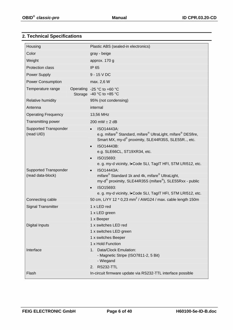
2. Technical Specifications
Housing Plastic ABS (sealed-in electronics)
Color gray - beige
Weight approx. 170 g
Protection class IP 65
Power Supply 9 - 15 V DC
Power Consumption max. 2,6 W
Temperature range OperatingStorage
-25 °C to +60 °C-40 °C to +85 °C
Relative humidity 95% (not condensing)
Antenna internal
Operating Frequency 13,56 MHz
Transmitting power 200 mW ± 2 dB
Supported Transponder(read UID)
• ISO14443A:e.g. mifare® Standard, mifare® UltraLight, mifare® DESfire,Smart MX, my-d® proximity, SLE44R35S, SLE55R.., etc.
• ISO14443B:e.g. SLE66CL, ST19XR34, etc.
• ISO15693:e. g. my-d vicinity, I•Code SLI, TagIT HFI, STM LRI512, etc.
Supported Transponder(read data-block)
• ISO14443A:mifare® Standard 1k and 4k, mifare® UltraLight,my-d® proximity, SLE44R35S (mifare®), SLE55Rxx - public
• ISO15693:e. g. my-d vicinity, I•Code SLI, TagIT HFI, STM LRI512, etc.
Connecting cable 50 cm, LiYY 12 * 0,23 mm2 / AWG24 / max. cable length 150m
Signal Transmitter 1 x LED red1 x LED green1 x Beeper
Digital Inputs 1 x switches LED red1 x switches LED green1 x switches Beeper1 x Hold Function
Interface 1. Data/Clock Emulation:- Magnetic Stripe (ISO7811-2, 5 Bit)- Wiegand
2. RS232-TTLFlash In-circuit firmware update via RS232-TTL interface possible
OBID® classic-pro Manual ID CPR.03.20-CD
FEIG ELECTRONIC GmbH Page 7 of 40 H60100-5e-ID-B.doc
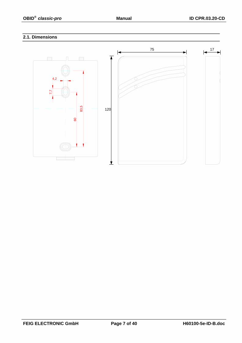
2.1. Dimensions
75 17
83,5
60
7,7
4,2
120

OBID® classic-pro Manual ID CPR.03.20-CD
FEIG ELECTRONIC GmbH Page 8 of 40 H60100-5e-ID-B.doc
2.2. Applicable Standards
RF approval
• Europe
• USA
EN 300 330
FCC 47 CFR Part 15
EMC EN 301 489
Safety
• Low Voltage
• Human Exposure
EN 60950
EN 50364
2.3. Approval
When properly used this radio equipment conforms to the essential requirements of Article 3 andthe other relevant provisions of the R&TTE Directive 1999/5/EC of March 99.
Equipment Classification according to ETSI EN 300 330 and ETSI EN 301 489: Class 2
FCC ID: PJMCPR03This device complies with Part 15 of the FCC Rules. Operation is subject to the followingtwo conditions:(1) this device may not cause harmful interference, and(2) this device must accept any interference received, including interference that maycause undesired operation.
Unauthorized modifications may void the authority granted under Federal communica-tions Commission Rules permitting the operation of this device.
OBID® classic-pro Manual ID CPR.03.20-CD
FEIG ELECTRONIC GmbH Page 9 of 40 H60100-5e-ID-B.doc
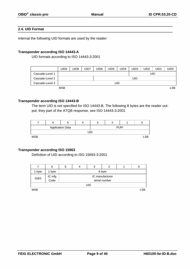
2.4. UID Format
Internal the following UID formats are used by the reader:
Transponder according ISO 14443-AUID formats according to ISO 14443-3:2001
UID9 UID8 UID7 UID6 UID5 UID4 UID3 UID2 UID1 UID0
Cascade-Level 1 UIDCascade-Level 2 UIDCascade-Level 3 UID
MSB LSB
Transponder according ISO 14443-BThe term UID is not specified for ISO 14443-B. The following 8 bytes are the reader out-put; they part of the ATQB response, see ISO 14443-3:2001
7 6 5 4 3 2 1 0
Application Data PUPIUID
MSB LSB
Transponder according ISO 15963Definition of UID according to ISO 15693-3:2001
7 6 5 4 3 2 1 0
1 byte 1 byte 6 byte
0xE0IC mfgCode
IC manufacturerserial number
UIDMSB LSB

OBID® classic-pro Manual ID CPR.03.20-CD
FEIG ELECTRONIC GmbH Page 10 of 40 H60100-5e-ID-B.doc
3. Installation
The ID CPR.03.20-CD is designed to be wall-mounted with or without a 60 mm flush-mounting box
3.1. Mounting
• The reader should not be mounted directly onto conductive materials, such as metal surfaces,metal frames (reinforcement) or metal-plated surfaces, as these surfaces will reduce the read-ing range. The clearance to such surfaces should be at least 30 mm.
• The distance between readers of the same design should not be less than 50 cm.
• Before final installation, the planned installation site should be checked for suitability.
• Only install the reader after successful configuration. The power supply must be disconnectedfor configuration (see also : 3.3. Configuration).
• Use the screws provided (3.2 x 25 mm) for installation on 60 mm DIN flush-mounting boxes.
• For other installation methods use 3 mm countersunk-head screws to DIN 963 or with a coun-tersunk head max. diameter of head 5.6 mm.
TOP
Assembling Disassembling

OBID® classic-pro Manual ID CPR.03.20-CD
FEIG ELECTRONIC GmbH Page 11 of 40 H60100-5e-ID-B.doc
3.2. Connection
Colour Function Descriptionred Vcc (+9 to +15 V DC)
black GND*Power Supply
green Data / Data0white Clock / Data1violet CLS / Card Present
Clock/Data interface(magnetic strip/ Wiegand)
grey LED greenbrown LED redyellow Beeperblue Hold
digital input**
pink RS232-TTL (Rx)red / blue RS232-TTL (Tx)
Service and Data-Output -Interface
grey / pink - N.C. -
*) If the power is not supplied via the controller the power supply GND must be connectedto the controller GND.
**) The digital inputs may only be wired to ground. Wiring to an external power supply maydestroy the input.
Controller
VccData / Data0
Clock / Data1CLS
LED greenLED redBeeper
HoldGND
redgreenwhitevioletgrey
brownyellowblueblack
pinkred/blue
+9..15 V DC
max. 150 m
RS232-TTL
RS232
max. 3 m
RS232 TxDRS232 RxD
OBID® classic-pro Manual ID CPR.03.20-CD
FEIG ELECTRONIC GmbH Page 12 of 40 H60100-5e-ID-B.doc
3.3. Configuration Procedure
Configuration is carried out by means of a ConfigCard. An ISO 15693 transponder can be used asConfigCard (e.g. Infineon my-d: SFR55V10P, Philips I-CODE SLI, Texas Instruments TagIT HFI etc.)
The configuration data are stored in a specified read/write data block on the transponder. TheConfigCard is also coded with identifiers which enable recognition as a ConfigCard.
The creation and modification of a ConfigCard could be done by the FEConfigCardTool which isavailable for Windows operating systems.
3.3.1. Default Configuration
The factory configuration of the reader is as follows:
• Reads serial numbers (UID) from ISO 14443 Type A, ISO 14443 Type B and ISO 15693 trans-ponders.
• Data output: Magstripe Track II, binary (80-bit) format.
3.3.2. Reloading the configuration
1. Switch on the power supply.
2. Hold the ConfigCard in the reading range during the configuration phase (8 seconds). Duringthis time the red and green LEDs flash alternately.
3. After the configuration is complete the reader automatically switches into normal mode.
Signals:The reader acknowledges a ConfigCard with the following signals:
1 x LED green + Beeper (1 sec.) ⇒ OKConfigCard has been processed, reader is operating with the new configuration
2 x LED red + Beep ⇒ FaultConfigCard CRC16 or ConfigCard Identifier is not read correctly.
⇒ Repeat procedure.⇒ Check the ConfigCard for correct programming.
Note:The ConfigCards are only recognized by the reader if the AFI is correct set.No signaling is possible.

OBID® classic-pro Manual ID CPR.03.20-CD
FEIG ELECTRONIC GmbH Page 13 of 40 H60100-5e-ID-B.doc
OBID® classic-pro Manual ID CPR.03.20-CD
FEIG ELECTRONIC GmbH Page 14 of 40 H60100-5e-ID-B.doc
4. Normal Operating Mode
Idle State (no Transponder detected):In idle state the reader is searching permanently for a Transponder. In this case the redLED is active.
Transponder detected:After a Transponder is detected by the ID CPR.03.20-CD the data's are transmitted viadata-/clock interface once and the beeper sounds for a short time. At the same time thered LED turns off for a period of 2 sec.
To transmit the data's a second time the Transponder must leave the detection field of theID CPR.03.20-CD for more then 1,5 seconds.
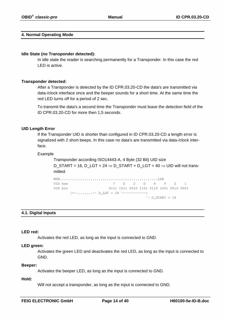
UID Length ErrorIf the Transponder UID is shorter than configured in ID CPR.03.20-CD a length error issignalized with 2 short beeps. In this case no data's are transmitted via data-/clock inter-face.
ExampleTransponder according ISO14443-A, 4 Byte (32 Bit) UID sizeD_START = 16, D_LGT = 24 ⇒ D_START + D_LGT = 40 ⇒ UID will not trans-mitted.
MSB................................................LSBUID hex 7 D 2 D 6 9 2 1UID bin 0111 1011 0010 1101 0110 1001 0010 0001 |<-........-- D_LGT = 24 ------------| `- D_START = 16
4.1. Digital Inputs
LED red:Activates the red LED, as long as the input is connected to GND.
LED green:Activates the green LED and deactivates the red LED, as long as the input is connected toGND.
Beeper:Activates the beeper LED, as long as the input is connected to GND.
Hold:Will not accept a transponder, as long as the input is connected to GND.

OBID® classic-pro Manual ID CPR.03.20-CD
FEIG ELECTRONIC GmbH Page 15 of 40 H60100-5e-ID-B.doc
4.2. Wiegand Interface
The Wiegand interface is designed for unidirectional for data output.
Data format / codingThe UID and DATA-BLOCK output is binary 1 to 1, as encoded on the transponder.
Parity bitsThe reader forms an odd and an even parity bit and encapsulates the output data.
The even parity bit is formed for the first half of the transmitted data, the odd parity bit forthe second half of the information transmitted. If there is an odd number of bits to betransmitted the middle bit is incorporated in the calculation of the even and odd parity bits.
Number of bits output = D_LGT + 2.
Timing
/Data0
/Data1
/CLStv ts
1 1 1
0 0 0
tpw tpi
tpw ≈ 50 µs
tpi ≈ 500 µs
tv = ts 10...12 ms

OBID® classic-pro Manual ID CPR.03.20-CD
FEIG ELECTRONIC GmbH Page 16 of 40 H60100-5e-ID-B.doc
4.2.1. UID
The transferred data volume is defined by the D_START and D_LGT parameters (see also: 5.1.Configuration Parameter).
Example:Example 1 MSB.....................................................LSBUID hex 0 2 5 8 7 B 2 D 6 9 2 1UID bin 0000 0010 0101 1000 0111 1011 0010 1101 0110 1001 0010 0001 |<----- D_LGT = 22 -------| `- D_START = 8 ee eeee eeee e ooo oooo ooooOutput (24 Bit) 1 11 1011 0010 1101 0110 1001 1 `- Even Parity Bit `- Odd Parity Bit
Example 2 MSB.....................................................LSBUID hex 0 2 5 8 7 B 2 D 6 9 2 1UID bin 0000 0010 0101 1000 0111 1011 0010 1101 0110 1001 0010 0001 |<------- D_LGT = 25 ---------| `- D_START = 6 eee eeee eeee ee ooo oooo oooo ooOutput (27 Bit) 1 111 1011 0010 1101 0110 1001 00 1 `- Even Parity Bit `- Odd Parity
e: Data bits for forming the even parity bito: Data bits for forming the odd parity bit
4.2.2. DATA-BLOCK
The transferred data volume is defined by the DB_ADR and D_LGT (see also: 5.1. ConfigurationParameter).

OBID® classic-pro Manual ID CPR.03.20-CD
FEIG ELECTRONIC GmbH Page 17 of 40 H60100-5e-ID-B.doc
4.3. Magstripe Track II Interface
The Magstripe Track II interface is designed for unidirectional for data output.
Encoding:Data output is in 5-bit code (4 data bits, 1 parity) according to ISO 7811-2 Track 2:
Raw Data ISO 7811-25 Bit Code
LSB........MSB / P
0x0 b 0 0 0 0 / 1
0x1 b 1 0 0 0 / 0
0x2 b 0 1 0 0 / 0
0x3 b 1 1 0 0 / 1
0x4 b 0 0 1 0 / 0
0x5 b 1 0 1 0 / 1
0x6 b 0 1 1 0 / 1
0x7 b 1 1 1 0 / 0
0x8 b 0 0 0 1 / 0
0x9 b 1 0 0 1 / 1
0xA* b 0 1 0 1 / 1
0xB* b 1 1 0 1 / 0
0xC* b 0 0 1 1 / 1
0xD* b 1 0 1 1 / 0
0xE* b 0 1 1 1 / 0
0xF* b 1 1 1 1 / 1
Start '%' b 1 1 0 1 / 0
Stop '?' b 1 1 1 1 / 1
* Characters are not specified as such in ISO 7811-2 and are only transmitted bythe reader for the UID binary 1:1 and DATA-BLOCK setting
LRC:XOR operation for all transmitted data (including start and stop sign).
OBID® classic-pro Manual ID CPR.03.20-CD
FEIG ELECTRONIC GmbH Page 18 of 40 H60100-5e-ID-B.doc
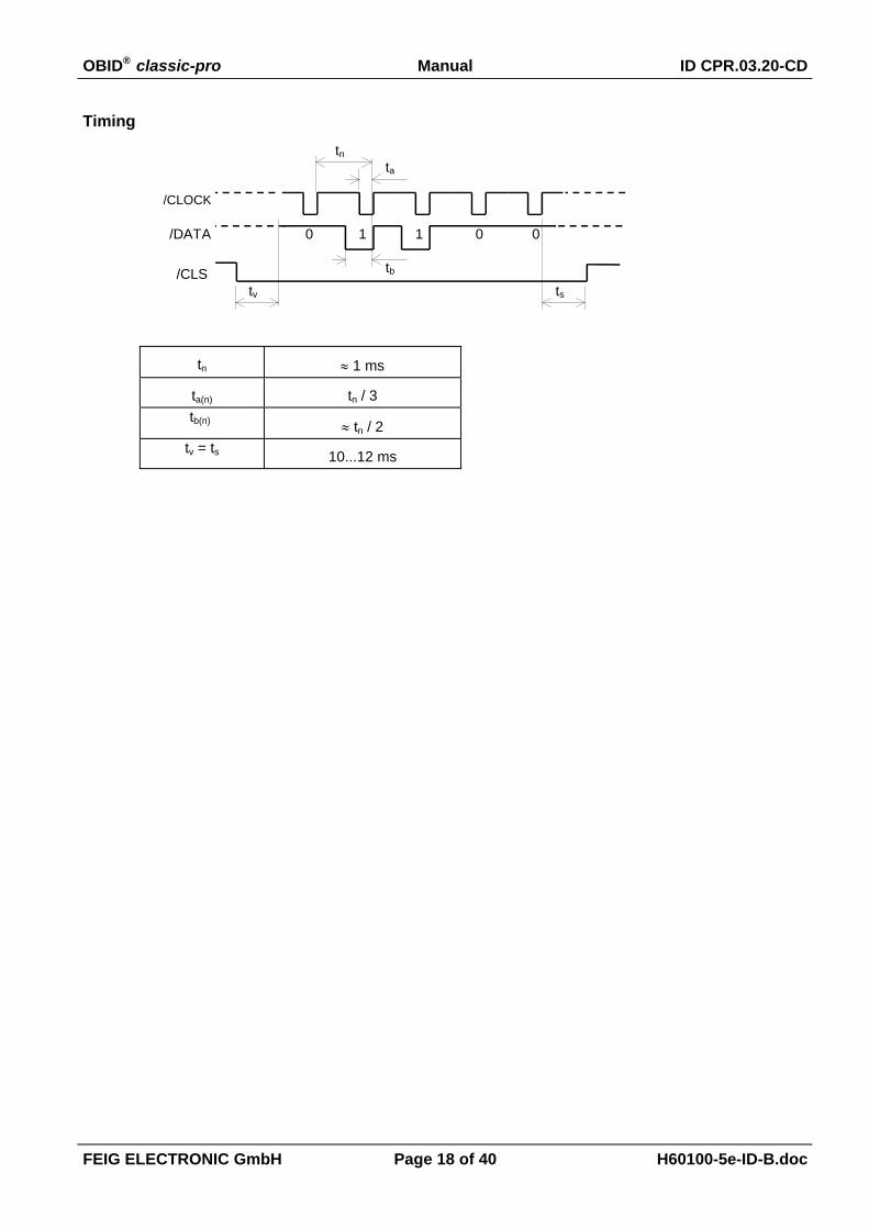
Timing
1 01 0
tnta
tb
/CLOCK
/DATA
/CLStv ts
0
tn ≈ 1 ms
ta(n) tn / 3tb(n) ≈ tn / 2
tv = ts 10...12 ms
OBID® classic-pro Manual ID CPR.03.20-CD
FEIG ELECTRONIC GmbH Page 19 of 40 H60100-5e-ID-B.doc
4.3.1. UID
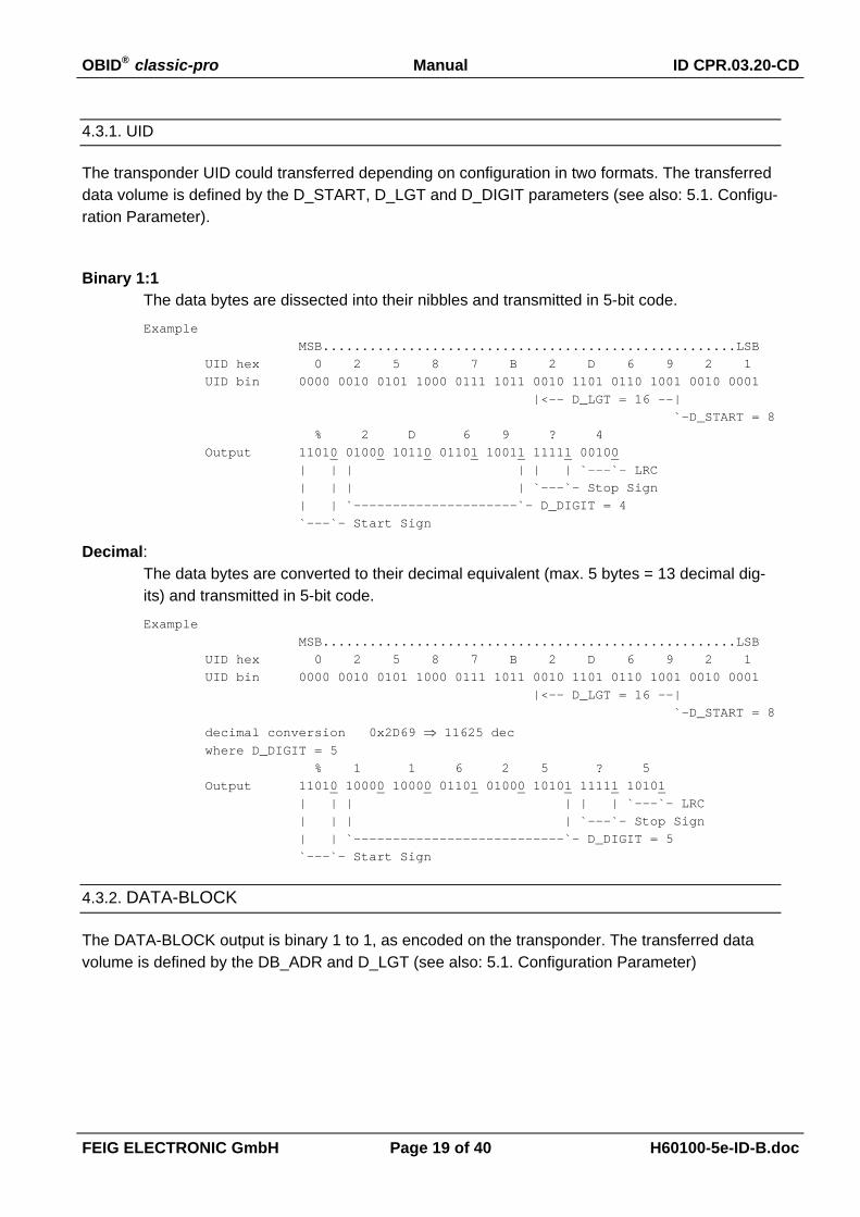
The transponder UID could transferred depending on configuration in two formats. The transferreddata volume is defined by the D_START, D_LGT and D_DIGIT parameters (see also: 5.1. Configu-ration Parameter).
Binary 1:1The data bytes are dissected into their nibbles and transmitted in 5-bit code.
Example MSB.....................................................LSBUID hex 0 2 5 8 7 B 2 D 6 9 2 1UID bin 0000 0010 0101 1000 0111 1011 0010 1101 0110 1001 0010 0001 |<-- D_LGT = 16 --| `-D_START = 8 % 2 D 6 9 ? 4Output 11010 01000 10110 01101 10011 11111 00100 | | | | | | `---`- LRC | | | | `---`- Stop Sign | | `---------------------`- D_DIGIT = 4 `---`- Start Sign
Decimal:The data bytes are converted to their decimal equivalent (max. 5 bytes = 13 decimal dig-its) and transmitted in 5-bit code.
Example MSB.....................................................LSBUID hex 0 2 5 8 7 B 2 D 6 9 2 1UID bin 0000 0010 0101 1000 0111 1011 0010 1101 0110 1001 0010 0001 |<-- D_LGT = 16 --| `-D_START = 8
decimal conversion 0x2D69 ⇒ 11625 decwhere D_DIGIT = 5 % 1 1 6 2 5 ? 5Output 11010 10000 10000 01101 01000 10101 11111 10101 | | | | | | `---`- LRC | | | | `---`- Stop Sign | | `---------------------------`- D_DIGIT = 5 `---`- Start Sign
4.3.2. DATA-BLOCK
The DATA-BLOCK output is binary 1 to 1, as encoded on the transponder. The transferred datavolume is defined by the DB_ADR and D_LGT (see also: 5.1. Configuration Parameter)

OBID® classic-pro Manual ID CPR.03.20-CD
FEIG ELECTRONIC GmbH Page 20 of 40 H60100-5e-ID-B.doc
4.4. Asynchronous Interface: RS232-TTL
The RS232-TTL Interface is designed for firmware update and for data output. For details aboutthe firmware update procedure please see chapter 7. Firmware update.
Encoding:In case of RS232-TTL data output the data's are encoded in ASCII format. The data bytesare dissected into their nibbles and transformed into the equivalent ASCII char before theyare transmitted.
hex Raw Data Transferred hexValue
ADCII char
0x0 0x30 '0'
0x1 0x31 '1'
0x2 0x32 '2'
0x3 0x33 '3'
0x4 0x34 '4'
0x5 0x35 '5'
0x6 0x36 '6'
0x7 0x37 '7'
0x8 0x38 '8'
0x9 0x39 '9'
0xA 0x41 'A'
0xB 0x42 'B'
0xC 0x43 'C'
0xD 0x44 'D'
0xE 0x45 'E'
0xF 0x46 'F'
The RS232 Settings are:Start bits 1
Data bits 8
Stop bits 1
Parity configurable see Parameter RS232-PARITY
Baud rate configurable see Parameter RS232-BAUD
OBID® classic-pro Manual ID CPR.03.20-CD
FEIG ELECTRONIC GmbH Page 21 of 40 H60100-5e-ID-B.doc
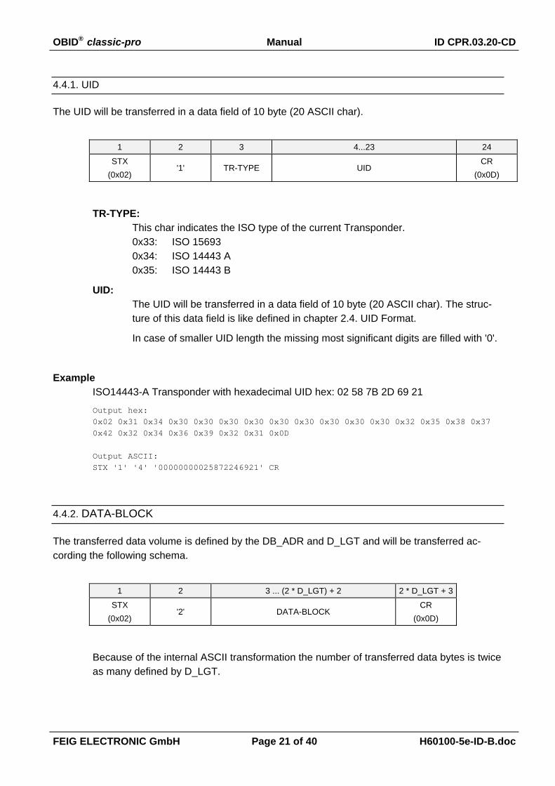
4.4.1. UID
The UID will be transferred in a data field of 10 byte (20 ASCII char).
1 2 3 4...23 24
STX(0x02)
'1' TR-TYPE UIDCR
(0x0D)
TR-TYPE:This char indicates the ISO type of the current Transponder.0x33: ISO 156930x34: ISO 14443 A0x35: ISO 14443 B
UID:The UID will be transferred in a data field of 10 byte (20 ASCII char). The struc-ture of this data field is like defined in chapter 2.4. UID Format.
In case of smaller UID length the missing most significant digits are filled with '0'.
ExampleISO14443-A Transponder with hexadecimal UID hex: 02 58 7B 2D 69 21
Output hex:0x02 0x31 0x34 0x30 0x30 0x30 0x30 0x30 0x30 0x30 0x30 0x30 0x32 0x35 0x38 0x370x42 0x32 0x34 0x36 0x39 0x32 0x31 0x0D
Output ASCII:STX '1' '4' '00000000025872246921' CR
4.4.2. DATA-BLOCK
The transferred data volume is defined by the DB_ADR and D_LGT and will be transferred ac-cording the following schema.
1 2 3 ... (2 * D_LGT) + 2 2 * D_LGT + 3
STX(0x02)
'2' DATA-BLOCKCR
(0x0D)
Because of the internal ASCII transformation the number of transferred data bytes is twiceas many defined by D_LGT.

OBID® classic-pro Manual ID CPR.03.20-CD
FEIG ELECTRONIC GmbH Page 22 of 40 H60100-5e-ID-B.doc
5. Reader Configuration - ConfigCard
A ConfigCard is a ISO 15693 Transponder with 4 byte block size, like Tag-it HFI (Texas Instru-ments), LRI512 (STMicroelectronics), I-Code SLI (Philips), etc.
For programming a ConfigCard with an individual configuration for the ID CPR.03 a ConfigurationKit is available. Which includes the Windows software FEConfigTool.
5.1. Configuration Parameter (ConfigData)
The following parameters are stored in ConfigData array in the ConfigCard.
Byte 0 1 2 3 4 5 6Contents TAG_DRV INTERFACE D_START D_LGT D_DIGIT SCAN-DATA DB_ADR
Default 0x07 0x00 0x00 0x20 0x0A 0x00 0x00
Byte 7 8 9 10 11 12 13
Contents RFU Mifare_KEY
Default 0x00 0x00 0x00 0x00 0x00 0x00 0x00
TAG_DRV:Defines the enabled Transponder types which are accepted from the reader.It's recommended to disable all Transponder types which are not used in the current ap-plication.
Bit: 7 6 5 4 3 2 1 0 TAG_DRV MK 0 0 0 0 C B A
A:b0: Driver for ISO14443-A Transponder is disabledb1: Driver for ISO14443-A Transponder is enabled
Bb0: Driver for ISO14443-B Transponder is disabledb1: Driver for ISO14443-B Transponder is enabled
Cb0: Driver for ISO15693 Transponder is disabledb1: Driver for ISO15693 Transponder is enabled
MK:Definition of the mifare_KEY usage for mifare standardb0: mifare_KEY is used as KEY Ab1: mifare_KEY is used as KEY B
OBID® classic-pro Manual ID CPR.03.20-CD
FEIG ELECTRONIC GmbH Page 23 of 40 H60100-5e-ID-B.doc
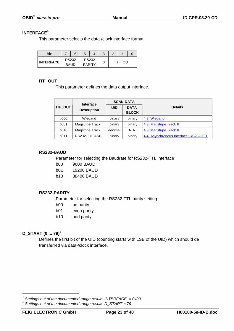
INTERFACE1
This parameter selects the data-/clock interface format
Bit: 7 6 5 4 3 2 1 0
INTERFACE RS232BAUD
RS232PARITY
0 ITF_OUT
ITF_OUTThis parameter defines the data output interface.
SCAN-DATAITF_OUT
InterfaceDescription UID DATA-
BLOCKDetails
b000 Wiegand binary binary 4.2. Wiegandb001 Magstripe Track II binary binary 4.3. Magstripe Track IIb010 Magstripe Track II decimal N.A. 4.3. Magstripe Track IIb011 RS232-TTL ASCII binary binary 4.4. Asynchronous Interface: RS232-TTL
RS232-BAUDParameter for selecting the Baudrate for RS232-TTL interfaceb00 9600 BAUDb01 19200 BAUDb10 38400 BAUD
RS232-PARITYParameter for selecting the RS232-TTL parity settingb00 no parityb01 even parityb10 odd parity
D_START (0 ... 79)2
Defines the first bit of the UID (counting starts with LSB of the UID) which should detransferred via data-/clock interface.
1 Settings out of the documented range results INTERFACE = 0x002 Settings out of the documented range results D_START = 79
OBID® classic-pro Manual ID CPR.03.20-CD
FEIG ELECTRONIC GmbH Page 24 of 40 H60100-5e-ID-B.doc
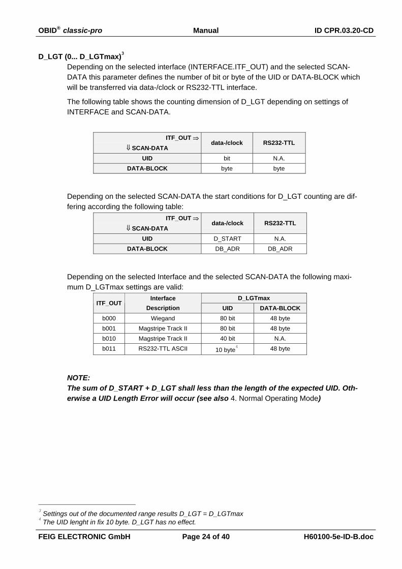
D_LGT (0... D_LGTmax)3
Depending on the selected interface (INTERFACE.ITF_OUT) and the selected SCAN-DATA this parameter defines the number of bit or byte of the UID or DATA-BLOCK whichwill be transferred via data-/clock or RS232-TTL interface.
The following table shows the counting dimension of D_LGT depending on settings ofINTERFACE and SCAN-DATA.
ITF_OUT ⇒⇓ SCAN-DATA
data-/clock RS232-TTL
UID bit N.A.DATA-BLOCK byte byte
Depending on the selected SCAN-DATA the start conditions for D_LGT counting are dif-fering according the following table:
ITF_OUT ⇒⇓ SCAN-DATA
data-/clock RS232-TTL
UID D_START N.A.DATA-BLOCK DB_ADR DB_ADR
Depending on the selected Interface and the selected SCAN-DATA the following maxi-mum D_LGTmax settings are valid:
D_LGTmaxITF_OUT
InterfaceDescription UID DATA-BLOCK
b000 Wiegand 80 bit 48 byteb001 Magstripe Track II 80 bit 48 byteb010 Magstripe Track II 40 bit N.A.b011 RS232-TTL ASCII 10 byte
4 48 byte
NOTE:The sum of D_START + D_LGT shall less than the length of the expected UID. Oth-erwise a UID Length Error will occur (see also 4. Normal Operating Mode)
3 Settings out of the documented range results D_LGT = D_LGTmax4 The UID lenght in fix 10 byte. D_LGT has no effect.
OBID® classic-pro Manual ID CPR.03.20-CD
FEIG ELECTRONIC GmbH Page 25 of 40 H60100-5e-ID-B.doc
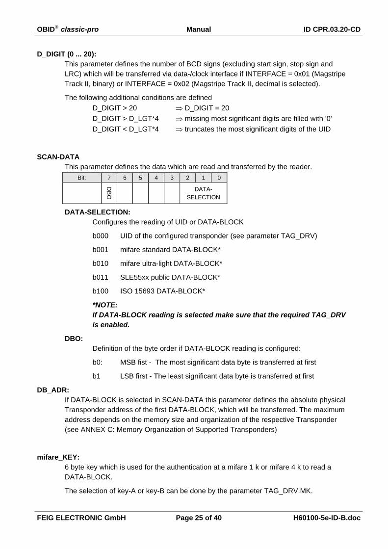
D_DIGIT (0 ... 20):This parameter defines the number of BCD signs (excluding start sign, stop sign andLRC) which will be transferred via data-/clock interface if INTERFACE = 0x01 (MagstripeTrack II, binary) or INTERFACE = 0x02 (Magstripe Track II, decimal is selected).
The following additional conditions are definedD_DIGIT > 20 ⇒ D_DIGIT = 20D_DIGIT > D_LGT*4 ⇒ missing most significant digits are filled with '0'D_DIGIT < D_LGT*4 ⇒ truncates the most significant digits of the UID
SCAN-DATAThis parameter defines the data which are read and transferred by the reader.
Bit: 7 6 5 4 3 2 1 0
DB
O DATA-SELECTION
DATA-SELECTION:Configures the reading of UID or DATA-BLOCK
b000 UID of the configured transponder (see parameter TAG_DRV)
b001 mifare standard DATA-BLOCK*
b010 mifare ultra-light DATA-BLOCK*
b011 SLE55xx public DATA-BLOCK*
b100 ISO 15693 DATA-BLOCK*
*NOTE:If DATA-BLOCK reading is selected make sure that the required TAG_DRVis enabled.
DBO:Definition of the byte order if DATA-BLOCK reading is configured:
b0: MSB fist - The most significant data byte is transferred at first
b1 LSB first - The least significant data byte is transferred at first
DB_ADR:If DATA-BLOCK is selected in SCAN-DATA this parameter defines the absolute physicalTransponder address of the first DATA-BLOCK, which will be transferred. The maximumaddress depends on the memory size and organization of the respective Transponder(see ANNEX C: Memory Organization of Supported Transponders)
mifare_KEY:6 byte key which is used for the authentication at a mifare 1 k or mifare 4 k to read aDATA-BLOCK.
The selection of key-A or key-B can be done by the parameter TAG_DRV.MK.

OBID® classic-pro Manual ID CPR.03.20-CD
FEIG ELECTRONIC GmbH Page 26 of 40 H60100-5e-ID-B.doc
5.2. ConfigCard - Data Structure
A ConfigCard is accepted by the Reader if all Identifier's and checksums are correct and the AFI isset to value 0x38.
The configuration is stored on the Transponder according to the following structure.Byte ⇒
Block-No. ⇓1 2 3 4
4 ConfigCard Identifier
5
6
7
ConfigData
8 ConfigData CRC_CONFIG
ConfigCard Identifier:The ConfigCard Identifier is one of the identification characteristics of a valid ConfigCardand is formatted as follows:
Byte 1 2 3 4
Content UID_CRC 'C'(0x43)
'2'(0x32)
UID_CRC:CRC16 checksum calculated above the 8 byte Transponder UID (see 5.2.1.CRC16 Calculation Algorithm for details)
AFI (Application Family Identifier) according ISO 15693-3 = 0x38A second identifier of a valid ConfigCard is the AFI which is stored in the AFI byte of theConfigCard.AFI most significant nibble = 3 (Identification)AFI least significant nibble = 8 (Data storage)
ConfigData:see 5.1. Configuration Parameter
CRC_CONFIG:CRC16 Checksum calculated above ConfigCard Identifier and ConfigData. (see 5.2.1.CRC16 Calculation Algorithm for details)
OBID® classic-pro Manual ID CPR.03.20-CD
FEIG ELECTRONIC GmbH Page 27 of 40 H60100-5e-ID-B.doc
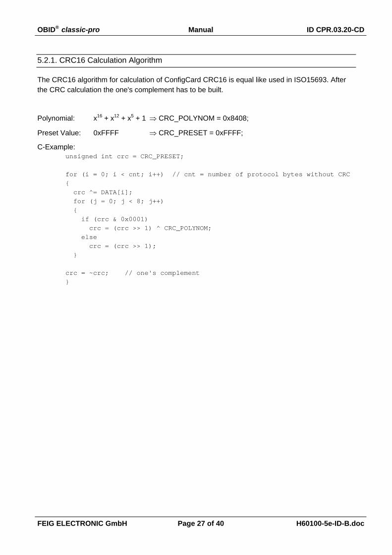
5.2.1. CRC16 Calculation Algorithm
The CRC16 algorithm for calculation of ConfigCard CRC16 is equal like used in ISO15693. Afterthe CRC calculation the one's complement has to be built.
Polynomial: x16 + x12 + x5 + 1 ⇒ CRC_POLYNOM = 0x8408;
Preset Value: 0xFFFF ⇒ CRC_PRESET = 0xFFFF;
C-Example:unsigned int crc = CRC_PRESET;
for (i = 0; i < cnt; i++) // cnt = number of protocol bytes without CRC{ crc ^= DATA[i]; for (j = 0; j < 8; j++) { if (crc & 0x0001) crc = (crc >> 1) ^ CRC_POLYNOM; else crc = (crc >> 1); }
crc = ~crc; // one's complement}
OBID® classic-pro Manual ID CPR.03.20-CD
FEIG ELECTRONIC GmbH Page 28 of 40 H60100-5e-ID-B.doc
6. FEConfCardTool
FEConfigCardTool is a part of the optional available ID CPR.03 Configuration Kit. FEConfigCard-Tool is a software for Microsoft Windows operating systems to prepare ConfigCards in a comfort-able way before installation.
FEConfigCardTool is designed for, Windows 2000 and Windows XP and requires depending onthe used reader one serial COM Port or one USB Port.
6.1. Installation of FEConfiCardTool
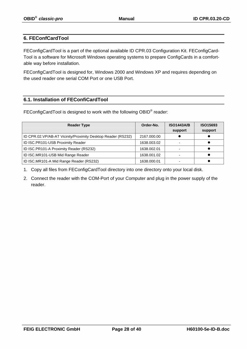
FEConfigCardTool is designed to work with the following OBID® reader:
Reader Type Order-No. ISO1443A/Bsupport
ISO15693support
ID CPR.02.VP/AB-AT Vicinity/Proximity Desktop Reader (RS232) 2167.000.00ID ISC.PR101-USB Proximity Reader 1638.003.02 -ID ISC.PR101-A Proximity Reader (RS232) 1638.002.01 -ID ISC.MR101-USB Mid Range Reader 1638.001.02 -ID ISC.MR101-A Mid Range Reader (RS232) 1638.000.01 -
1. Copy all files from FEConfigCardTool directory into one directory onto your local disk.
2. Connect the reader with the COM-Port of your Computer and plug in the power supply of thereader.

OBID® classic-pro Manual ID CPR.03.20-CD
FEIG ELECTRONIC GmbH Page 29 of 40 H60100-5e-ID-B.doc
6.2. Starting FEConfigCardTool
After installation the FEConfigCardTool you can start FEConfigCardTool.exe from your local disk.
After the first program start the following screen appears.
Depending on the connected reader select first the port (USB or COM). If a RS232 reader is usedselect the COM port on which the reader is connected and push the 'Detect' button. If FEConfig-CardTool has detected the reader at the selected COM-Port the reader type will be displayed.
If the reader was detected you can close the dialog with the 'OK' button and reach the FEConfig-CardTool main dialog.
If the reader was detected once and is connected at the same COM port for a second time theFEConfigCardTool main dialog appears after a the program was started immediately.

OBID® classic-pro Manual ID CPR.03.20-CD
FEIG ELECTRONIC GmbH Page 30 of 40 H60100-5e-ID-B.doc
6.3. FEConfigCardTool Functions
The FEConfigCardTool main screen includes the whole functionality of FEConfigCardTool.
Menus:Under the header line the following functions are accessible:
File:
Open:Opens a XML formatted configuration file.
Save As:Saves the current configuration settings into a XML formatted configura-tion file.
Quit:Leaves the program.
Options:
Detect Reader:Opens the reader detection dialog.
OBID® classic-pro Manual ID CPR.03.20-CD
FEIG ELECTRONIC GmbH Page 31 of 40 H60100-5e-ID-B.doc
Buttons:On the right side the following buttons are visible:
Read ConfigCard:Reads a ConfigCard Transponder which lays on the configuration reader.
Write ConfigCard:Writes the current configuration settings into the ConfigCard Transponder whichlays on the configuration reader.
Clear Screen:Resets the dialog.
Exit:Leaves the program.
Configuration Dialogs:The configuration dialogs are dynamical activated or deactivated. Depending on the se-lected option only the necessary dialogs will be activated. Each input mask represent aconfiguration parameter which is described in chapter 5.1. Configuration Parameter.Please refer to this description to get detailed information about each parameter.
ConfigCard DescriptionThis filed can be used to store a free description with your configuration.
Scan-Data:Configuration Parameter SCAN-DATA.DATA-SELECTION ((see 5.1. Configura-tion Parameter)
UID TruncationConfiguration Parameter D_START, D_LGT and D_DIGIT (see 5.1. ConfigurationParameter).
Data Block Definition:Configuration Parameter DB_ADR, D_LGT and SCAN_DATA.DBO (see 5.1.Configuration Parameter)
Interface:Configuration Parameter INTERFACE (see 5.1. Configuration Parameter).
Transponder Driver:Configuration Parameter TAG_DRV (see 5.1. Configuration Parameter).
mifare Key:Configuration Parameter mifare_KEY and TAG_DRV.MK (see 5.1. ConfigurationParameter)
OBID® classic-pro Manual ID CPR.03.20-CD
FEIG ELECTRONIC GmbH Page 32 of 40 H60100-5e-ID-B.doc
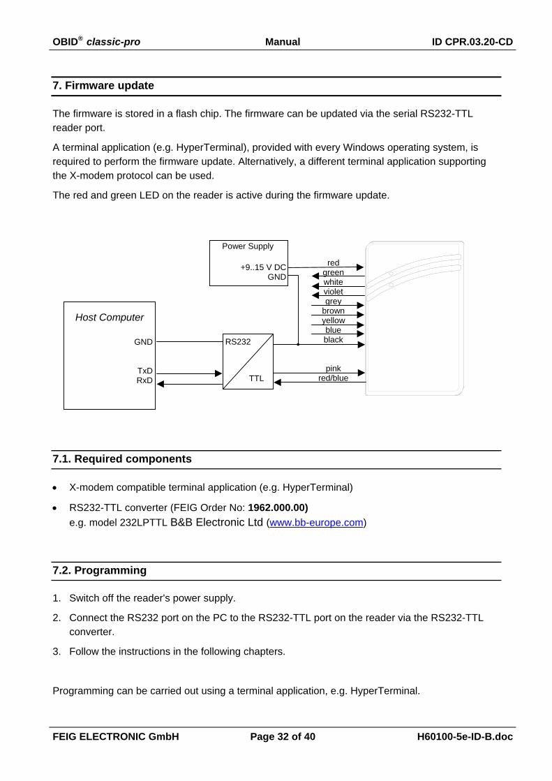
7. Firmware update
The firmware is stored in a flash chip. The firmware can be updated via the serial RS232-TTLreader port.
A terminal application (e.g. HyperTerminal), provided with every Windows operating system, isrequired to perform the firmware update. Alternatively, a different terminal application supportingthe X-modem protocol can be used.
The red and green LED on the reader is active during the firmware update.
7.1. Required components
• X-modem compatible terminal application (e.g. HyperTerminal)
• RS232-TTL converter (FEIG Order No: 1962.000.00)e.g. model 232LPTTL B&B Electronic Ltd (www.bb-europe.com)
7.2. Programming
1. Switch off the reader's power supply.
2. Connect the RS232 port on the PC to the RS232-TTL port on the reader via the RS232-TTLconverter.
3. Follow the instructions in the following chapters.
Programming can be carried out using a terminal application, e.g. HyperTerminal.
Host Computer
GND
TxDRxD
redgreenwhitevioletgrey
brownyellowblueblack
pinkred/blue
+9..15 V DCGND
RS232
TTL
Power Supply
OBID® classic-pro Manual ID CPR.03.20-CD
FEIG ELECTRONIC GmbH Page 33 of 40 H60100-5e-ID-B.doc
7.2.1. Starting and setting up HyperTerminal
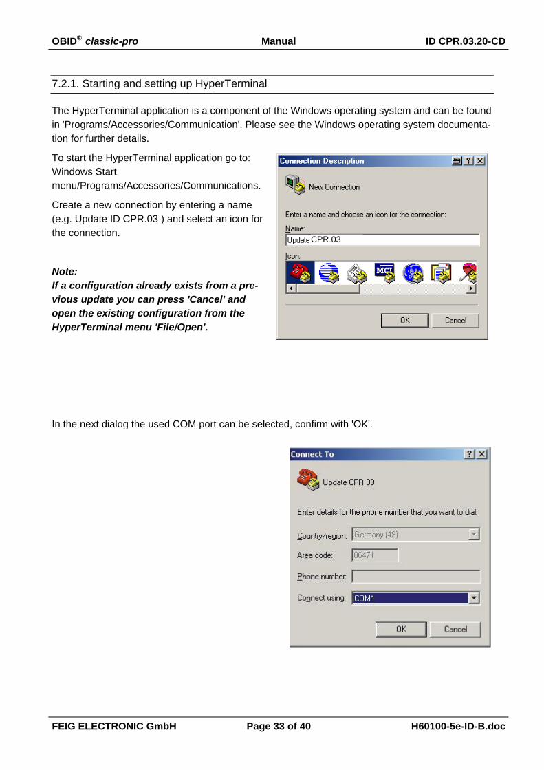
The HyperTerminal application is a component of the Windows operating system and can be foundin 'Programs/Accessories/Communication'. Please see the Windows operating system documenta-tion for further details.
To start the HyperTerminal application go to:Windows Startmenu/Programs/Accessories/Communications.
Create a new connection by entering a name(e.g. Update ID CPR.03 ) and select an icon forthe connection.
Note:If a configuration already exists from a pre-vious update you can press 'Cancel' andopen the existing configuration from theHyperTerminal menu 'File/Open'.
In the next dialog the used COM port can be selected, confirm with 'OK'.
CPR.03

OBID® classic-pro Manual ID CPR.03.20-CD
FEIG ELECTRONIC GmbH Page 34 of 40 H60100-5e-ID-B.doc
Enter the connection settings in the COM portProperties dialog:
If, after pressing 'OK', the message: 'COM1could not be opened......' appears, the COMport is probably being used by a different ap-plication.
7.2.2. Reader synchronisation 'PPPPPPPP...'
NOTEUse capital letters only for command input!
1. Start sending 'P' characters (0x50)
2. Switch on the reader's power supply while sending 'P' characters.
Synchronize the PC interface to the reader interfaceby sending at least 15 'P' characters (0x50).
The reader replies with the bootloader prompt, thered LED lights up.
It then waits for a maximum of 8 seconds for abootloader command input (FLASHALL, VERIFY,RESET). If it receives either no command or only awrong one it leaves the bootloader mode.
OBID® classic-pro Manual ID CPR.03.20-CD
FEIG ELECTRONIC GmbH Page 35 of 40 H60100-5e-ID-B.doc
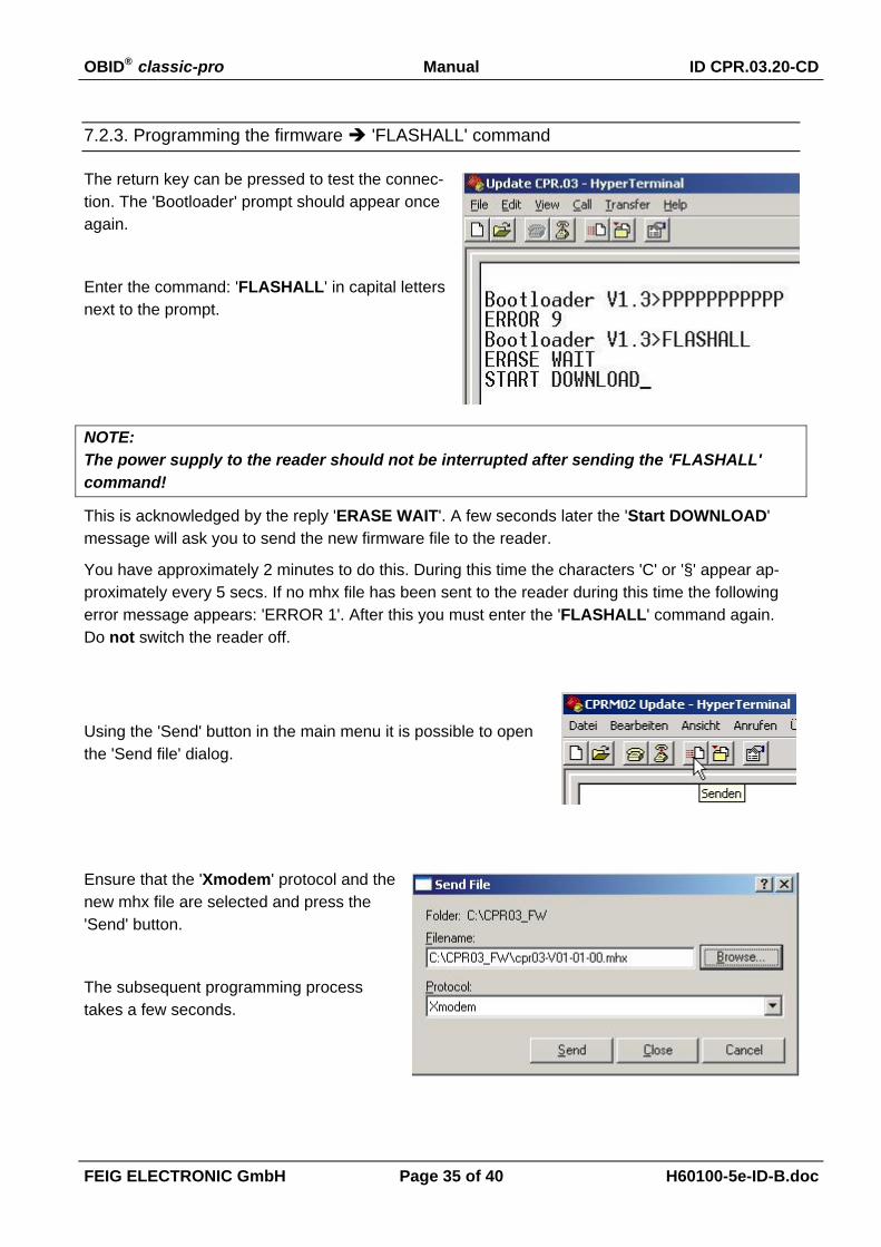
7.2.3. Programming the firmware 'FLASHALL' command
The return key can be pressed to test the connec-tion. The 'Bootloader' prompt should appear onceagain.
Enter the command: 'FLASHALL' in capital lettersnext to the prompt.
NOTE:The power supply to the reader should not be interrupted after sending the 'FLASHALL'command!
This is acknowledged by the reply 'ERASE WAIT'. A few seconds later the 'Start DOWNLOAD'message will ask you to send the new firmware file to the reader.
You have approximately 2 minutes to do this. During this time the characters 'C' or '§' appear ap-proximately every 5 secs. If no mhx file has been sent to the reader during this time the followingerror message appears: 'ERROR 1'. After this you must enter the 'FLASHALL' command again.Do not switch the reader off.
Using the 'Send' button in the main menu it is possible to openthe 'Send file' dialog.
Ensure that the 'Xmodem' protocol and thenew mhx file are selected and press the'Send' button.
The subsequent programming processtakes a few seconds.

OBID® classic-pro Manual ID CPR.03.20-CD
FEIG ELECTRONIC GmbH Page 36 of 40 H60100-5e-ID-B.doc
Successful programming is acknowledged with'OK'.

OBID® classic-pro Manual ID CPR.03.20-CD
FEIG ELECTRONIC GmbH Page 37 of 40 H60100-5e-ID-B.doc
7.2.4. Verifying the firmware 'VERIFY' command
In order to ensure that no errors have oc-curred when programming the new firmwarethe 'VERIFY' command can be used to com-pare the programmed firmware to the mhx-file.
Enter the 'VERIFY' command and press the'Send' button to select the mhx-file again.
The procedure was successful when the OKmessage appears.
7.2.5. Exiting the Bootloader 'RESET' command
The Bootloader can be exited with the 'RESET' command. After entering 'RESET' the reader per-forms a reset.

OBID® classic-pro Manual ID CPR.03.20-CD
FEIG ELECTRONIC GmbH Page 38 of 40 H60100-5e-ID-B.doc
ANNEX
ANNEX A: Revision History of Documentation
Revision Description
2• Addition of of FEConfigCardTool description.
• Correction of CRC16 calculation.
• Correction of ConfigCard error signals.
3 • unpublished draft preliminary version
4
Described Firmware: 02.00.00
• RS232-TTL Interface is useable for transponder data output
• Beneath the UID also Data-Blocks can be read from different Transponder
• ConfigCard Identifier changed from 'C1' to 'C2'
• possibility to configure Keys for mifare standard Transponder
• Option SCAN-DATA.DBO to change the byte order if DATA-BLOCK reading is selected.
• Timing of magstripe format corrected to 1 ms per Bit..
• Description of FEConfigCardTool V2.0
5Described Firmware: 02.00.00
• Adding of additional reader types for FEConfigCardTool.
OBID® classic-pro Manual ID CPR.03.20-CD
FEIG ELECTRONIC GmbH Page 39 of 40 H60100-5e-ID-B.doc
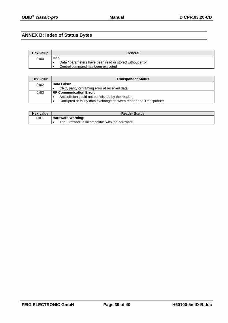
ANNEX B: Index of Status Bytes
Hex-value General0x00 OK:
• Data / parameters have been read or stored without error• Control command has been executed
Hex-value Transponder Status0x02 Data False:
• CRC, parity or framing error at received data. 0x83 RF Communication Error:
• Anticollision could not be finished by the reader.• Corrupted or faulty data exchange between reader and Transponder
Hex-value Reader Status 0xF1 Hardware Warning:
• The Firmware is incompatible with the hardware
OBID® classic-pro Manual ID CPR.03.20-CD
FEIG ELECTRONIC GmbH Page 40 of 40 H60100-5e-ID-B.doc
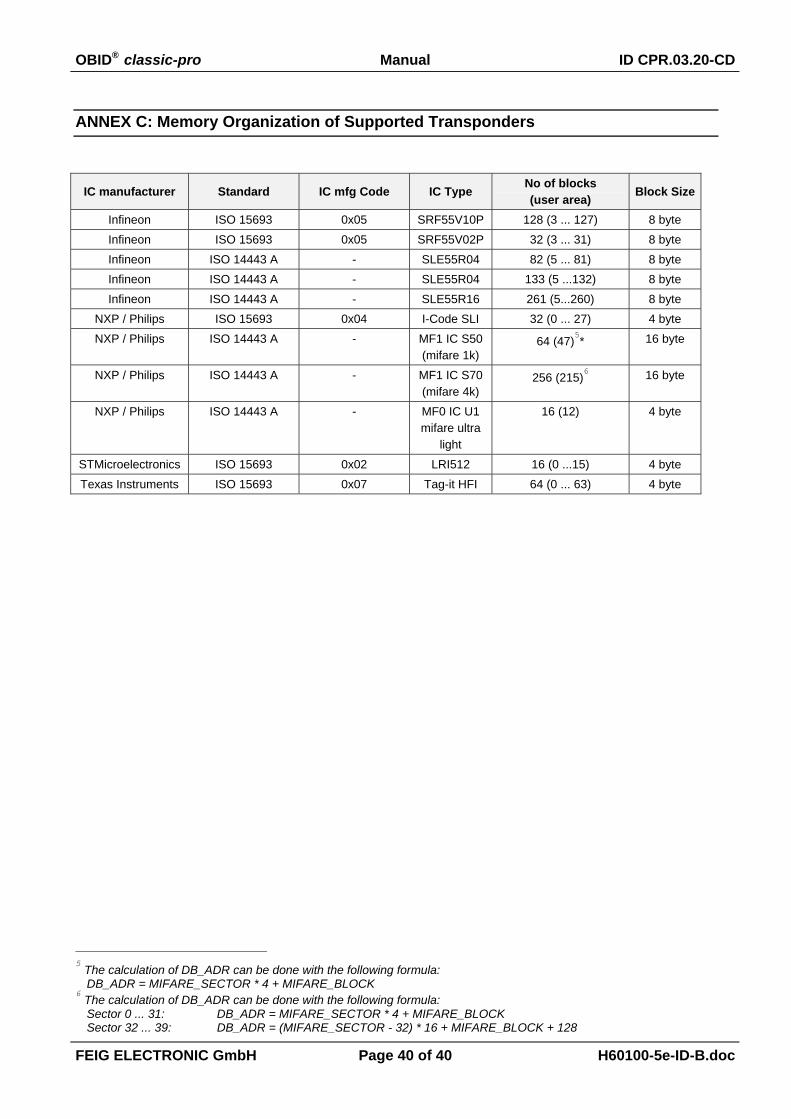
ANNEX C: Memory Organization of Supported Transponders
IC manufacturer Standard IC mfg Code IC TypeNo of blocks(user area) Block Size
Infineon ISO 15693 0x05 SRF55V10P 128 (3 ... 127) 8 byteInfineon ISO 15693 0x05 SRF55V02P 32 (3 ... 31) 8 byteInfineon ISO 14443 A - SLE55R04 82 (5 ... 81) 8 byteInfineon ISO 14443 A - SLE55R04 133 (5 ...132) 8 byteInfineon ISO 14443 A - SLE55R16 261 (5...260) 8 byte
NXP / Philips ISO 15693 0x04 I-Code SLI 32 (0 ... 27) 4 byteNXP / Philips ISO 14443 A - MF1 IC S50
(mifare 1k)64 (47)
5* 16 byte
NXP / Philips ISO 14443 A - MF1 IC S70(mifare 4k)
256 (215)6 16 byte
NXP / Philips ISO 14443 A - MF0 IC U1mifare ultra
light
16 (12) 4 byte
STMicroelectronics ISO 15693 0x02 LRI512 16 (0 ...15) 4 byteTexas Instruments ISO 15693 0x07 Tag-it HFI 64 (0 ... 63) 4 byte
5 The calculation of DB_ADR can be done with the following formula:
DB_ADR = MIFARE_SECTOR * 4 + MIFARE_BLOCK6 The calculation of DB_ADR can be done with the following formula:
Sector 0 ... 31: DB_ADR = MIFARE_SECTOR * 4 + MIFARE_BLOCKSector 32 ... 39: DB_ADR = (MIFARE_SECTOR - 32) * 16 + MIFARE_BLOCK + 128