Embed Size (px)
Citation preview

iColor Tile MXPrecision-controlled direct-view interior LED panel with dynamic color light

iColor Tile MX Powercore Product Guide2
iColor Tile MX Precision-controlled direct-view interior LED panel with dynamic color light iColor Tile MX is a full-color LED light panel for creating stunning light art and accents in a variety of surface-mounted and recessed applications. Each 23.5 x 23.5 in (597 x 597 mm) panel has 144 individually addressable nodes to enable an infinite variety of effects at an unprecedented level of fine-grained control and intricacy.
• Aninnovativecanvas—With144individuallyaddressable, high-intensity, full-color LED nodes, iColor Tile MX can serve as a canvas for creative lighting designs, effects, animation, and large-scale video displays.
• Seamlesseffects—iColorTileMXisabaseunitfor indoor applications, ideal for wall and ceiling installations. Install behind a custom panel, or use the available impact-resistant, translucent white diffuser lens for seamless, uniform optical effects.
• Highlyconsistentcolor—Optibin,ourproprietary binning optimization process, ensures optimalcolorconsistencyfromfixturetofixture.
• Versatilemountingoptions—Designedforrecessand surface mounting on walls or ceilings. Capable ofretrofittingceilingtiles.Standardleadercablesof 25 ft (7.6 m), 50 ft (15.2 m), and 100 ft (30.5 m) let you position power / data supplies at an appropriatedistancefromfixtures.
• Industry-leadingcontrols—WorkswithPhilipsfullrangeofcontrollers,includingVideoSystemManager,LightSystemManager,iPlayer 3, or third-party controllers.
• Quicksetupforcomplexandlarge-scaleinstallations—EachiColorTileMXfixtureoffersapre-configured,12x12gridof144LEDnodes,withafixedpixelpitchof2in(51mm)oncenter.Fixtures can be installed flush to extend consistent pixel pitch across multiple tiles. Fixtures can be easily leveled and installed using the included wall-mounting cleat or mounting through-holes in the fixture housing.
Superior Light OutputEach iColor Tile MX fixture produces full-color light output of 559 nits.
Atotalof113iColorTilefixturescreatedacheckerboard-likecanvasattheWorldLightingFairinTokyo,Japan.Morphing colors, patterns, and animations were displayed across the fixtures’ 16,272 individually controllable, full-color LED nodes.
Phot
ogra
phy:
Nica
sa &
Par
tner
s

iColor Tile MX Powercore Product Guide 3
The X Factor in Direct-View LED LightingTheUSmayhaveAmerican Idol, but The X Factor—createdbyIdoljudgeSimonCowell—rulestheairwavesintheUK.Withanestimated10millionregularviewers,thetalentsearchprogramisoneoftheUK’stop-watchedentertainmentshows. Its vibrant set combines several applications of LED technology to stellar effect.
Designers Dave Davey and Christopher George conceptualized an LED floor that would generate dynamic effects to uniquely complement the action on stage. More than 170 iColor Tile fixtures were installed beneath the slightly frosted stage floor,makingeachfixture’s144full-colornodesvisibleforcrispdefinition.Theapproximately 25,000 individually controllable iColor Tile nodes are collectively capable of displaying sophisticated designs, patterns, and video across the entire floor.
TheiColorTilefixturesarecontrolledbyVideoSystemManager(VSM),asophisticatedEthernet-basedlightingcontrollerandvideoserverfromPhilipsColorKinetics.Videocontentwasgeneratedusingathird-partyvideocreationand
editing software system, then downloaded to the VideoSystemEngine,thehardware component ofVSMresponsibleforstreaming video to the iColor Tile fixtures.
“The extraordinary visual impactofColorKineticssystems coupled with their ease of control and rugged, durable naturemakesthemanideal solution for The X Factor set,” said lighting director Dave Davey. “LED technology allows a completely new level of creative flexibility in lighting design, and the saturated colors translate very effectively on camera.”
Because the entire system is under digital
control, the set designers and lighting director can dynamically change or fine-tune the appearance of The X Factorsetonthefly.AndbecausetheirLEDsradiatenoheat, iColor Tile fixtures can be positioned virtually anywhere on the set . . . even underfoot!
Lighting Design: Dave Davey and Christopher GeorgePhotography: Louise Stickland

iColor Tile MX Powercore Product Guide4
SpecificationsDue to continuous improvements and innovations, specifications may change without notice.
Luminance (nits)
Lensing On-AxisCandela ViewingAngle
No lens 559 cd / m2 110°
Frosted lens 227 cd / m2 120°
Photometrics
* L50 = 50% lumen maintenance (when light output drops below 50% of initial output).Ambientluminairetemperaturesspecified.Lumenmaintenancecalculationsare based on lifetime prediction graphs supplied by LED source manufacturers. Calculationsforwhite-lightLEDfixturesarebasedonmeasurementsthatcomplywithIESLM-80-08testingprocedures.Refertowww.philipscolorkinetics.com/support/appnotes/lm-80-08.pdfformoreinformation.
4.125 in(105 mm)
2 in(51 mm)
Wall Cleat
Impact ResistantDiffuser Lens
23.5 in Square(597 mm)
20 in(508 mm)
Item Specification Details
OutputLumen Maintenance* 50,000+ hours L50 @ 50° C (full output)
LED Channels Red / Green / Blue
Electrical
InputVoltage 7.5VDCviaPDS-60caandsPDS-60ca
PowerConsumption 62Wmaximumatfulloutput,steadystate
PowerFactor .98@120VAC
Control
Interface sPDS-480ca7.5V(Ethernet) PDS-60ca7.5V(Pre-programmedorDMX/Ethernet)
ControlSystemPhilipsfullrangeofcontrollers,includingVideoSystemManagerPro,LightSystemManager,andiPlayer3,orthird-partycontrollers
Physical
Dimensions (Height x Width x Depth)
23.5 x 23.5 x 2 in (597 x 597 x 51 mm), without lens
Weight 23lb(10.4kg)Tile 5lb(2.3kg)Lens
Housing Sheetmetal,whitepowder-coatedfinish
Lens Impact-resistant copolyester with carbon steel mounting hardware
Fixture Connections Integrated 3-pin connector
Temperature Ranges
-4°–122°F (-20°–50°C)Operating ≥32°F(≥0°C)Handling -4°–122°F (-20°–50°C)Startup -22°–185°F(-30°–85°C)Storage
Humidity 0 – 95%, non-condensing
MaximumFixturesPerPower/DataSupply
PDS-60ca7.5V:1 sPDS-480ca7.5V:8
CertificationandSafety
Certification UL/cUL,FCCClassA,CE
Environment DryLocation,IP20

iColor Tile MX Powercore Product Guide 5
Fixtures and Power / Data SuppliesiColorTileMXfixturesarepartofacompletesystemwhichincludes:
• Oneormorepower/datasupplies
• TwoLeaderCablestoattacheachiColorTileMXfixturetoapower/datasupply
• Optionalwhitetranslucentlensesfordiffusingfixtures’lightoutput
• AnyPhilipscontroller,includingVideoSystemManagerPro,LightSystemManager,andiPlayer3,oranythird-partycontroller
UseItemNumberwhenorderinginNorthAmerica.
Included in the boxiColorTileMXfixtureMounting alignment cleat(6) Corner clips
Item Type Item Number Philips12NC
iColor TileMXfixtures and accessories
iColor Tile MX White 101-000071-00 910503701017
iColor Tile MX Lens White Translucent 101-000044-00 910503700564
Leader Cables
Black 25 ft (7.6 m) 108-000045-00 910503700696
Black 50 ft (15.2 m) 108-000045-01 910503700697
Black 100 ft (30.5 m) 108-000045-02 910503700698
Power/datasuppliesPDS-60ca7.5V
Pre-programmed 109-000015-00 910503700093
DMX / Ethernet 109-000015-03 910503700094
sPDS-480ca7.5V Ethernet 109-000022-00 910503700107

iColor Tile MX Powercore Product Guide6
InstallationiColor Tile MX is a direct-view light panel for creating stunning light art, accent lighting, and video displays in a variety of surface-mounted and recessed applications. iColor Tile MX is a 23.5 x 23. 5 in (597 x 597 mm) panel with 144 individually addressable nodes for intricate, fine-grained control. Each panel can be installed with a white translucent lens, or behind a scrim or other translucent surface.
Because of their potential complexity, iColor Tile MX installations require upfront planningforconfiguring,positioning,andmountingfixtures.Planningincludesunderstanding how to position fixtures in relation to power / data supplies and the numberoffixtureseachpower/datasupplycansupport.Planningforvideodisplaysinvolves additional considerations, such as pixel pitch, minimum and maximum viewing distances, sampling, and display resolution.
Allinstallationsinvolvethreemainsteps:
1. Create a lighting design plan and layout grid
2. Mountfixtures
3. Address,configure,andtestfixtures
Owner / User ResponsibilitiesIt is the responsibility of the contractor, installer, purchaser, owner, and user to install, maintain, and operate iColor Tile MX fixtures in such a manner as to comply with all applicable codes, state and local laws, ordinances, and regulations. Consult with the appropriate electrical inspector to ensure compliance.
DMX or Ethernet Control?iColor Tile MX installations can be controlled via either DMX or Ethernet. DMX is appropriate for simple installations, or for installations where all nodes or fixtures operateinunison—forexample,foraccentingorsimplecolor-changinglightshows.
Each node in an iColor Tile MX fixture is is controlled by three sequential DMX addresses—oneforred,oneforgreen,andoneforblue.ADMXuniverseconsistsof 512 addresses, so the maximum number of individually controllable tri-color nodes available in a DMX universe is 170 (170 x 3 = 510).
Because it is not subject to the DMX addressing limitations, Ethernet is the preferred environment for complex, color-changing light shows and video displays, both of which require large numbers of individually controllable nodes. In an Ethernet environment, each power / data supply effectively acts as its own universe.
DMXinstallationsrequiretheuseofaPDS-60ca7.5Vpower/datasupply,whilethesPDS-480ca7.5Vpower/datasupplyisEthernetonly.
E Refer to the iColor Tile MX Installation Instructions for specif ic warning and caution statements.

iColor Tile MX Powercore Product Guide 7
Considerations for Video DisplaysIn addition to the planning required for all iColor Tile MX installations, planning for video displays involves special considerations such as pixel pitch, minimum and maximum viewing distances, sampling, and display resolution.
Pixel Pitch and Viewing Distances for Video DisplaysWhenusingiColorTileMXfixturestodisplayvideo,eachnodeactsasapixelinthedisplay. Images on an LED video display appear to be sharper to the human eye as the distancetothedisplayincreases.Likewise,imagesappearlessvisibleasthedistancedecreases.Thespacingbetweenpixels,knownasthepixel pitch, determines the minimumandmaximumviewingdistancesfordiscerniblevideooutput.Pixelpitchismeasured center-to-center. Nodes in iColor Tile MX fixtures have a fixed pixel pitch of 2 in (51 mm).
You can achieve a consistent pixel pitch across multiple iColor Tile MX fixtures by installing fixtures side by side at the minimum allowable distance. Nodes are positioned along each edge of the fixture in such as a way as to maintain 2 in (51 mm) on center node spacing across fixtures when fixtures are installed as close together as possible.
The following calculations provide general guidelines for determining minimum and maximum viewing distances for a grid of iColor Tile MX fixtures, mounted as close togetheraspossible:
• Todetermineminimumviewingdistance,multiplypixelpitchby100distanceunits. Atapixelpitchof2in(51mm),theminimumviewingdistanceis16.7ft(5.1m).
• Todeterminethemaximumviewingdistancefordiscerniblevideo,multiplythescreenheightby20distanceunits.Forexample,ifthescreenis20fixturesor40ft(12.2m)high,thenthemaximumviewingdistanceforrecognizablevideois800ft(243.8m).
• LEDscreensarevisiblebeyondthemaximumviewingdistancefordiscerniblevideo. To determine the maximum viewing distance that still creates visual impact, multiply the screen height by 50 units. For example, a screen 40 ft (12.2 m) high will continue to create visual impact at 2000 ft (609.6 m).
Working with Video Display ResolutionsThe resolution of an LED video display equals the total number of vertical and horizontalpixels—thegreaterthepixelcount,thegreatertheresolution.
• TheresolutionofVSEProdigitalvideois1024x768
• TheresolutionofPALvideois704x576
• TheresolutionofNTSCvideois704x480
iColor Tile MX fixtures have a fixed pixel pitch of 2 in (51 mm) on center in both directions
E VSE Pro, or Video System Engine Pro, is the hardware component of Video System Manager Pro, an integrated video controller from Philips Color Kinetics. Visit www.philipscolorkinetics.com/ls/controllers/vsmpro/ for complete information
Install iColor Tile MX fixtures as close together as possible to maintain a pixel pitch of 2 in (51 mm) across fixtures

iColor Tile MX Powercore Product Guide8
Reproducingavideosignalwith1:1pixelmappingonanLEDdisplayrequiresasubstantialpixelcount.Forexample,trueNTSCvideooutputrequires337,920pixels,PALoutputrequires405,504pixels,anddigitalvideooutputrequires786,432pixels.
However,youcanuseacontrollersuchasPhilipsVideoSystemManagerProtoreduce the required pixel count for any video format by sampling pixels from the source video to match your installation.
For example, if you sample every tenth line of pixels horizontally and vertically, you can retain the correct aspect ratio while exponentially reducing the pixel count. From a distance, even with the video output reduced by a factor of 10, the human eye can still discern video images because the the aspect ratio has been preserved andtheresolutionissufficientlydense.AVSEdigitalvideodisplaysamplingeverytenth pixel would have a pixel count of 7,752 yet still display discernible digital video output.
Create a Lighting Design Plan and Layout GridEven for relatively simple installations, it’s good practice to create a lighting design plan. For complex installations displaying light shows with dynamic effects, and especiallyforEthernet-basedvideodisplays,suchaplanisessential.Alightingdesign plan is typically an architectural diagram or other diagram that shows the physical layout of the installation, including the appropriate positioning and spacing of all fixtures, power / data supplies, power sources, controllers, cables, and other requiredhardware.ForEthernetinstallations,theplanshouldrecordtheIPaddressof each power / data supply and the number of fixtures connected to each power / data supply.
Keepthefollowingconsiderationsinmindwhencreatingalightingdesignplanandlayoutgrid:
• Determinetheappropriatelocationofeachpower/datasupplyinrelationtothefixtures,andofthefixturesinrelationtoeachother.YouconnecteachiColorTileMXfixturetotwoavailablepower/datasupplyportsusingtwoLeaderCables of 25 ft (7.6 m), 50 ft (15.2 m), or 100 ft (30.5 m).
Power / Data Supply iColor Tile MXLeader Cables
• Onanarchitecturaldiagramorotherdiagramthatshowsthephysicallayoutofthe installation, identify the locations of all switches, controllers, power supplies, andfixtures.
• Nodesineachfixturearesequentiallyandautomaticallyaddressedbythepower/datasupplyorcontroller.Itisthereforeimportanttoensurethateachfixtureinamulti-fixtureinstallationisinstalledinthesameorientation.Consistentorientation is especially critical when using dynamic effects or video.
• InEthernetenvironments,eachpower/datasupplyisidentifiedwithauniqueIPaddress.WerecommendrecordingtheIPaddressofeachpower/datasupply
E Refer to the Installation Instructions or Specif ication Sheet of your power / data supply for guidelines on configuring and positioning the power / data supply in relation to a controller or Ethernet switch.
E For designs where the acceptable level of discernible video may be more or less demanding, or for help with your specif ic installation, contact Philips Color Kinetics Application Engineering Services for assistance.

iColor Tile MX Powercore Product Guide 9
on a layout grid. For complex installations with many power / data supplies, we recommendassigningmeaningfulIPaddressestoeachpower/datasupplysothattheir locations are easy to identify.
Start the Installation1. Installallpower/datasupplies,includinganyinterfaceswithcontrollers.Power/
datasuppliessendpowerandcontrolsignalstofixturesovertheLeaderCables.
2. Verifythatalladditionalsupportingequipment(switches,controllers)isinplace.
3. Ensure that all additional parts (for example, optional iColor Tile MX lenses) and tools are available.
Mount the FixturesYou mount iColor Tile MX fixtures to a vertical surface using the the included mounting alignment cleat and the fixture’s 10 pre-drilled mounting holes, with fasteners appropriate for the mounting surface.
You install iColor Tile MX fixtures in ceilings using the fixture’s four mounting tabs and 12-gauge hanger wire to attach the fixture to secure anchor points overhead.
MakesurethepowerisOFFbeforemountingandconnectingiColorTileMXfixtures.
Determine Fixture SpacingWheninstallingmultiplefixturestocreateavideowallorothercontinuouspanelfor displaying effects, you must butt-mount the fixtures to ensure consistent pixel spacing.
• Toachieveminimumhorizontalfixturespacing,allow3.6in(91mm)betweenmounting alignment cleats, measured on center.
• Toachieveminimumverticalfixturespacing,allow23.6in(599mm)betweenmounting alignment cleats.
Wheninstalled,thetopedgeofthefixturehousingextends1.5in(38mm)abovethecenter-line of the mounting alignment cleat’s screw holes.
23.6 in (599 mm)minimum
3.6 in (91 mm)minimum
1.5 in(38 mm)

iColor Tile MX Powercore Product Guide10
Wall-Mounting iColor Tile MX Fixtures
1. Usingapencilorchalklineandlevel,markthehorizontallocationsforeachmounting alignment cleat.
2. Alignthetopedgeofeachcleattotheappropriatemark,andattachittothewallusing nine fasteners appropriate for the mounting surface.
3. Orientfixturestop-uptoensureproperdisplayofvisualeffects.(Themountingcleatlipislocatedtowardthefixture’stopedge.)
4. Slidethemountingcleatlipofeachfixtureontoamountingalignmentcleat.
5. Attacheachfixturetothemountingsurfaceusing10suitable#10screws.
Ceiling-Mounting iColor Tile MX Fixtures
iColor Tile MX fixtures are designed to fit into 2 x 2 ft (609 x 609 mm) suspended ceilingframes.SinceceilingframesarenotadequatetosafelysuspendiColorTileMXfixtures,youmustuse12-gaugehangerwireandwirehangerscrewsforsecureoverhead installation.
1. Orientallfixturesinthesamedirectiontoensureproperdisplayofvisualeffects.(Themountingcleatlipislocatedtowardthefixture’stopedge.)
2. Bendthefourceilingmounttabsperpendiculartoeachfixture’sbackplate.
3. Thread 12-gauge hanger wire through each tab, and attach wires to secure anchor points using hanger wire screws appropriate for the mounting surface.
4. Adjustwirelengthstoalignfixtureswiththesuspendedceilingheight.
E The alignment cleat is intended to align the f ixture during installation, but it is not intended to support the f ixture in a permanent installation.
C23 lbs (10kg)
Top

iColor Tile MX Powercore Product Guide 11
Make Power and Data ConnectionsiColorTileMXfixturesaredesignedtoworkwith7.5VDCpower/datasuppliesfromPhilipsColorKinetics.Power/datasuppliessendpoweranddatatoiColorTileMXfixturesovertwoLeaderCables.EachsPDS-480ca7.5Vcanpowerupto8fixturesinEthernetinstallations,whileeachPDS-60ca7.5Vcanpoweronefixtureineither Ethernet or DMX installations.
MakesurethepowerisOFFbeforeconnectingiColorTileMXfixtures.
Connecting to the sPDS-480ca 7.5V Power / Data Supply1.ConnecttwoLeaderCablestothethree-pinconnectorsonbothfixturecables
byturningthefixturecables’grommetsclockwise.UsecautionwhenhandlingtheLeaderCablesorfixturecablesinsub-freezingtemperatures,asthewiringcanbecomebrittleandbreak.
2. ConnecteachLeaderCabletoavailablepowerportsonthebackofthepower/data supply housing.
3. Repeatforeachfixtureintheinstallation.
C
≤ 0ºc
3.06 in78 mm
.98 in25 mm
.63 in16 mm
3.69 in94 mm
1.1 in28 mm
.25 in6 mm
Leader Cable connector dimensions
PDS-60ca7.5V 1
sPDS-480ca7.5V 8
Maximum strands per power / data supply
sPDS-480ca7.5V

iColor Tile MX Powercore Product Guide12
Connecting to the PDS-60ca 7.5V Power / Data Supply
1. Remove the power / data supply cover.
2. RemovethecoverofthetransmitterPCAjunctionboxontheLeaderCablebyexpanding the four tabs on the side and sliding the cover from the base.
3. Connectline,common,ground,anddatatotheprovidedterminalblock,thenreplacethecoverofthetransmitterPCAjunctionbox.
4. Connect the Leader Cable connectors to available ports inside the power / data supply housing.
PDS-60ca7.5V
BlueStripe
Black
BlueRed
+DataData–
Red
BlueBlue/WhiteBlack
Red
BlueBlue/WhiteBlack
3.06 in77.8 mm
.98 in25 mm
.63 in16 mm
Transmitter PCA junction box dimensions
E If using conduit, remove the transmitter PCA junction box cover from the Leader Cable, as described here, before pulling the cable through the conduit, then replace the junction box cover.

iColor Tile MX Powercore Product Guide 13
5. Securethepower/datasupplycover.
6. Repeat steps 1 – 5 for each power / data supply in the installation.
Install iColor Tile MX Lenses (Optional)iColor Tile MX lenses, available separately, are translucent white lenses that can be used to blend the light output from a fixture’s 144 nodes.
1. Positionalensoverafixture,aligningthequarter-turnfastenerswiththefourattachmentholeslocatedatthecornersofthefixturehousing.
1
246
53
PDS-60ca7.5V
C27 lbs (12kg)
iColor Tile MX Powercore Product Guide14
2. Firmlyseatthelensinthefixturehousing.
3.WithaPhillipsscrewdriver,pushandturnthespring-loadedfasteners90ºclockwise.Whenproperlyattached,thefastenersstopfirmlyafteraquarterturn
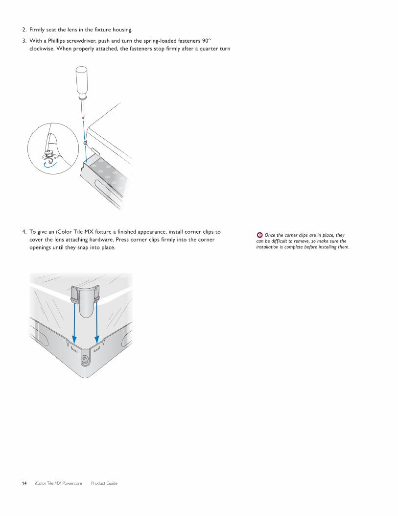
4. TogiveaniColorTileMXfixtureafinishedappearance,installcornerclipstocoverthelensattachinghardware.Presscornerclipsfirmlyintothecorneropenings until they snap into place.
E Once the corner clips are in place, they can be diff icult to remove, so make sure the installation is complete before installing them.

iColor Tile MX Powercore Product Guide 15
Address and Configure the FixturesMakesurethepowerisONbeforeaddressingandconfiguringfixtures.
Power/datasuppliesandcontrollersworktogethertostreamdatatotheiColorFlex MX strands in your installation.
• EachindividualiColorTileMXnodeisassignedthreeconsecutiveDMXaddresses,oneforred,oneforgreen,andoneforblue.ADMXuniverseconsistsof 512 addresses, so the maximum number of individually controllable nodes in a DMX universe is 170 (170 x 3 = 510).
WhenusingaPDS-60ca7.5Vpower/datasupplywithDMXcontrol,youprogram the power / data supply rather than addressing the iColor Tile MX fixturesdirectly.YouuseSmartJackPro(oriPlayer3)withQuickPlayProaddressing software to set a base DMX address for the power / data supply, and tospecifythenodequantityofeachattachedfixture(144).
Forlightingdesignswherenodesworkinunison,allnodesshouldbesettothesame DMX addresses. For dynamic light show designs that show different colors on different nodes simultaneously, you must assign DMX addresses to each node. StartingwithitsbaseDMXaddress,PDS-60caautomaticallyassignsasequenceofaddresses to iColor Tile MX nodes.
• Becauseyouarelimitedto170individuallycontrollablenodesperDMXuniverse(effectivelyonefixturewith144nodes),Ethernetisthepreferredenvironmentforvideo displays and dynamic light shows with intricate effects.
EachEthernet-basedpower/datasupplycomespre-programmedwithauniqueIPaddress,sothepower/datasupplyfunctionsasitsownuniverse.WhencreatingalightmapwithacontrollerormediaserversuchasLightSystemManagerorVideoSystemManagerPro,eachiColorTileMXnodeautomaticallyreceivesaunique identifier.
Youcandiscoverallpower/datasuppliesbyIPaddressusingQuickPlayPro,LightSystemManager,orVideoSystemManagerPro.Forlargeinstallations,and especially for video displays, we recommend giving power / data supplies meaningfulIPaddressestostreamlineinstallation,mapping,testing,andtroubleshooting.Whenreaddressingpower/datasupplies,youwillneedthelayoutgridyoucreatedwhenyourecordedeachpower/datasupply’sIPaddressduring installation planning.
For complete details on addressing and configuring fixtures, controllers, and power /data supplies, refer to the Addressing and Configuration Guide or the User Guide or SpecificationSheetforyourcontrollerorpower/datasupply.
E You can download the QuickPlay Pro software and the Addressing and Configuration Guide from www.philipscolorkinetics.com/support/addressing/

Philips Color Kinetics3 Burlington Woods DriveBurlington, Massachusetts 01803 USATel 888.385.5742Tel 617.423.9999Fax 617.423.9998www.philipscolorkinetics.com
Copyright © 2010 – 2012 Philips Solid-State Lighting Solutions, Inc. All rights reserved. Chromacore, Chromasic, CK, the CK logo, Color Kinetics, the Color Kinetics logo, ColorBlast, ColorBlaze, ColorBurst, eW Fuse, ColorGraze, ColorPlay, ColorReach, iW Reach, eW Reach, DIMand, EssentialWhite, eW, iColor, iColor Cove, IntelliWhite, iW, iPlayer, Optibin, and Powercore are either registered trademarks or trademarks of Philips Solid-State Lighting Solutions, Inc. in the United States and / or other countries. All other brand or product names are trademarks or registered trademarks of their respective owners. Due to continuous improvements and innovations, specifications may change without notice.Cover Photo: Courtesy of Louise Stickland DAS-000071-00 R02 5-12