Embed Size (px)
Citation preview

Page 1 of 27
ICEpower1000ASP 1000W Professional ICEpower Amplifier with ICEpower Supply Version 1.5 Contents General Description ..................................................................................... 2 Block Diagram ............................................................................................. 3 Connection Diagram.................................................................................... 3 Absolute Maximum Ratings ......................................................................... 5 Power Specifications .................................................................................... 6 Audio Specifications .................................................................................... 6 Electrical Specifications ................................................................................ 7 Timing Specifications ................................................................................... 7 Thermal Specifications ................................................................................. 7 Disturbances on the Mains........................................................................... 8 Mechanical Specifications ............................................................................ 8 Typical Performance Characteristics ............................................................. 9 High Current Output ................................................................................. 15 Efficiency vs. Output Power ....................................................................... 16 Loading ..................................................................................................... 17 Features..................................................................................................... 17 Protection Features .................................................................................... 19 Input/Output Interfaces.............................................................................. 20 Thermal Design.......................................................................................... 22 Fuses ......................................................................................................... 22 Physical Dimensions ................................................................................... 23 Safety Standards........................................................................................ 26 ESD Warning ............................................................................................. 26 Packaging and Storing ............................................................................... 26
Bang & Olufsen ICEpower a/s, Gl. Lundtoftevej 1b, DK-2800 Kgs. Lyngby Phone [45] 45 20 36 00, Fax [45] 45 20 36 99, CVR-no. 25053591 [email protected], www.icepower.bang-olufsen.com

ICEpower1000ASP, 1000W Professional ICEpower Amplifier with ICEpower Supply Version 1.5
Page 2 of 27
Figure 1: ICEpower1000ASP Size15 cm x 23.3 cm x 5.7 cm
General Description
The ICEpower1000ASP is a high quality audio power solution capable of generating 1000W RMS output directly from selectable 115/230 volt mains. The ICEpower1000ASP integrates the conventional power supply and amplifier into one highly compact and lightweight solution with state-of-the-art performance. Applications include: • Active speakers and subwoofers • Installation audio products • High-end stereo and multi-channel amplifiers For full range multi-way or multi-channel applications up to two additional ICEpower1000A or ICEpower500A amplifiers may be powered from the DC-bus connector. The ±12.8 volt outputs of the ICEpower1000ASP also provide general purpose auxilary supplies for external circuitry. The aluminum extrusion includes slots that accept 3mm thread forming screws for easy mounting to any chassis or back plate. The ICEpower1000ASP is protected against short-circuits, overload and over-heating and the on-board fuse and EMI filtering provides a CE and FCC approved design. Key Specifications • 1000W @ 0.01% THD+N, 100 Hz, 4Ω • 1175W @ 1% THD+N, 1kHz, 4Ω • 118dBA dynamic range • THD+N < 0.2%, 0.1W – 1100W, 4Ω • Bandwidth limit = 38 kHz (8Ω) • Total efficiency 79% • Stand-by power dissipation typically 4.1W • Mains connection is class 1 (with earth)
Key Features • Very rugged construction for professional use • Comprehensive protection scheme • Suitable for CE approved designs • Power output for ICEpower500A and/or 1000A • ±12.8 volt auxiliary output • Selectable mains 115/230Vac • Safety conforms to: UL6500 and others • EMI conforms to: EN55103-1 EN55103-2 FCC part 15b Class A

ICEpower1000ASP, 1000W Professional ICEpower Amplifier with ICEpower Supply Version 1.5
Page 3 of 27
Block Diagram
DC-blockingand mute
Rectificationand filteringEMI filter
110/230Vselectorand fuse
DC/DCconverter
withisolation
Buffering
Inputbuffer
Output stageand filteringClipping
MECCcontrol and
COMmodulation
80V
+12V-12VPGND
Vo+
Vo-
Live
Neutral
Earth
Vi+
Vi-
Clip AGND Standby/protect MonitorClip_off
AGND
120V
Figure 2: ICEpower1000ASP block diagram
Connection Diagram
10KΩ 30nF
EARTH/HEAT SINK
Figure 3: ICEpower1000ASP connections

ICEpower1000ASP, 1000W Professional ICEpower Amplifier with ICEpower Supply Version 1.5
Page 4 of 27
The plug interface of the ICEpower1000ASP modules has four industry standard connectors selected for long-term reliability.
AC Connector Specification (P3) The ICEpower1000ASP is Class 1 equipment and therefore must have an earth connection. Types: JST B3(6-2,4,5)P-VH PIN Function Description
1 Neutral Neutral AC 2 Line Phase AC 3 Earth Safety earth connection
Table 1: AC Connector Specification
Signal Connector Specification (P2) Type: JST 9-pole PH-connector PIN Function Description Type 1 Earth Connected directly to mains earth. Earth 2 Soft clip Soft clip indication (open collector). Output 3 Standby/protect Control pin for standby control (Internal pull-up). Input & Output 4 Monitor Unbalanced attenuated output signal. Output 5 Soft clip off Control pin for disabling the soft clipping circuit. Input 6 AGND Ground terminal for the signal section. GND 7 AGND Ground terminal for the signal section. GND 8 Vi- Negative input (balanced input buffer). Audio Input 9 Vi+ Positive input (balanced input buffer). Audio Input
Table 2: Signal Connector Specification.
DC-bus Connector Specification (P1) Type: JST 6P-VH-B PIN Function Description Type 1 PGND Power supply Ground GND 2 Vp2 (80V) Power supply 80V Output 3 PGND Power supply Ground GND 4 Vp1 (120V) Power supply 120V Output 5 Vcc (+12.8V) Power supply +12.8V Output 6 Vss (-12.8V) Power supply –12.8V Output
Table 3: DC-bus Connector Specifications.
Speaker Connector Specification (P4) Type: JST 4P-VH-B PIN Function Description Type 1+2 Vo+ “Hot” balanced audio power output terminal. Output 3+4 Vo- “Cold” balanced audio power output terminal. Output
Table 4: Speaker Connector Specification

ICEpower1000ASP, 1000W Professional ICEpower Amplifier with ICEpower Supply Version 1.5
Page 5 of 27
Absolute Maximum Ratings
Absolute maximum ratings indicate limits beyond which damage may occur.
Mains Input Section Symbol Parameter Value Unit
ACmax Maximum off-line voltage 115VAC setting Maximum off-line voltage 230VAC setting
132.5 265
VAC
ACmin Minimum off-line voltage 115VAC setting Minimum off-line voltage 230VAC setting
901)
1901) VAC,60Hz VAC,50Hz
F Mains frequency range 115VAC
Mains frequency range 230VAC
55 – 6545 - 55
Hz Hz
Ifuse1)
Fuse rating 115V Fuse rating 230V
T10T6.3
AH AH
Table 5: Absolute Maximum Ratings, mains input section 1) The ICEpower1000ASP will operate at lower levels but the output power will be reduced. If the off-line voltage is too low the ICEpower1000ASP switches off. 2) See fuses section for details
DC-Bus Symbol Parameter Value Unit
I80V3) Maximum current draw from Vp2 (80V) 7 A
I120V3) Maximum current draw from Vp1 (120V) 9 A
I+12.8V4) Maximum current draw from Vcc (+12.8V) 0.8 A
I-12.8V4) Maximum current draw from Vss (-12.8V) -0.8 A
Table 6: Absolute Maximum ratings, DC-bus.
3) The stated value is the maximum current available from the power supply when the internal amplifier is idle. Note that this power bus is only intended for use with other ICEpower amplifiers as shown in the ICEpower ASP-series Designer’s Manual. 4) The +/-12V outputs are not short circuit protected and must be fused to avoid damage. See the ICEpower ASP-series Designer’s Manual.
Input Section Symbol Parameter Value Unit
Vin+ , Vin- Maximum voltage range on pin ±12.85) V Standby/protect Maximum voltage range on pin 0-12.86) V Soft clip off Maximum voltage range on pin 0-12.86) V
Table 7: Absolute Maximum ratings, input section.
Output Section Symbol Parameter Value Unit
Rload Minimum load 2 Ω Iout
7) Maximum current draw from amplifier output
40 A
CL Maximum purely capacitive load 470 nF Soft clip Maximum voltage range on pin 0-12.86) V Monitor Maximum voltage range on pin 0-12.86) V
Table 8: Absolute Maximum ratings, output section.
5) From Vss to Vcc. 6) From 0 to Vcc. 7) The over current protection will act to protect the amplifier
Thermal Section Symbol Parameter Value Unit
Ta Max. operating ambient temperature 50 OC
Table 9: Absolute Maximum ratings, thermal section.

ICEpower1000ASP, 1000W Professional ICEpower Amplifier with ICEpower Supply Version 1.5
Page 6 of 27
Power Specifications
Unless otherwise specified. Ta=25 OC, f=1kHz, Load=4Ω. Symbol Parameter Conditions Min Typ Max Unit Vp1 Nominal DC voltage 1 Off-line input within range - 120 - V Vp2 Nominal DC voltage 2 Off-line input within range - 80 - V Vcc Positive analog supply Off-line input within range - 12.8 - V Vss Negative analog supply Off-line input within range - -12.8 - V TPmax Time of maximum rated output power 1000W out. No preheating. - 15 - s PT Continuous output power8) without
thermal shutdown. Thermal stab. @ Ta = 25 OC. 4Ω, no external heatsink.
- 85 - W
PT Continuous output power8) without thermal shutdown.
Thermal stab. @ Ta = 50 OC. 4Ω, no external heatsink.
- 40 - W
PFTC FTC rated output power 0-3kHz9) 4Ω, No external heatsink - 150 - W Pq Quiescent power dissipation Po = 0W - 15.8 - W Pstby Stand-by power dissipation Amplifier disabled - 4.1 - W η Power Efficiency
(4 ohm load) Po = 1000W, 230V mains Po = 500W, 230V mains
- 79 78
-
%
Table 10: Power specifications
6) The module is mounted vertically in free air. Continuous output power can be improved by the means of external heat sink or forced convection. 7) The power bandwidth is limited to protect the output Zobel network.
Audio Specifications
Unless otherwise specified, f=1kHz, PO =1W, Ta = 25 OC, soft clip enabled Symbol Parameter Conditions Min. Typ. Max. Units PO Output power @ 0.2%THD+N
10Hz < f < 20kHz (AES17 measurement filter) 10)
RL = 4Ω. RL = 8Ω. RL = 4Ω, 1% THD+N
---
1100 525
1175
- - -
W W W
THD+N THD+N in 4Ω (AES17 measurement filter) 10)
f = 100Hz, PO =1W - 0.007 0.015 %
THD+N Maximal THD+N in 4Ω (AES17 measurement filter) 10)
10Hz < f < 20kHz 100mW < Po < 1000W
- 0.2 0.3 %
VN,O Output referenced idle noise A-weighted 10Hz < f < 20kHz
65 80 115 μV
AV Nominal Voltage Gain f = 1 kHz 26.7 27.2 27.7 dB f Frequency response 20Hz - 20kHz, All loads - ±0.5 ±1.0 dB fu Upper bandwidth limit
(-3dB) RL = 8Ω RL = 4Ω
--
38 31
- -
kHz kHz
fl Lower bandwidth limit (-3dB)
RL = 8Ω RL = 4Ω
--
5.3 5.3
- -
Hz Hz
Zo Abs. output impedance f = 1kHz - 5 10 mΩ ZL Load impedance range 2 4 ∞ Ω D Dynamic range A-weighted 115 118 120 dB
Table 11: Audio specifications.
8) An Audio Precision AES17 20 kHz 7th order measurement filter is used for measurements. The frequency 6.67 kHz corresponds to the worst-case situation where both 2nd and 3rd harmonics are within the audio band.
ICEpower1000ASP, 1000W Professional ICEpower Amplifier with ICEpower Supply Version 1.5
Page 7 of 27
Electrical Specifications
Unless otherwise specified, Ta=25 OC. Symbol Parameter Conditions Min Typ Max Unit fo Offset switching frequency Idle 320 350 380 kHz fs Switching frequency range Idle to full scale variation 60 - 380 kHz fsmps Switching frequency power supply - 100 - kHz VOFF,Diff Differential offset on output terminals Input terminated - - ±50 mV VOFF,CM Common mode offset on output
terminals Input terminated - Vp1/2 ±10% V
Table 12: Electrical specifications
Timing Specifications
Symbol Parameter Conditions Min Typ Max Unit Tacd Power supply start up delay. Time from min. AC to all power supplies are
good. 450 ms
tsd Switching start up delay Time from all power supplies are good 1200 ms tpsd
11) Shutdown delay Supply fail or Standby pin 200 μs
Table 13: Timing Specifications.
11) Only valid with the circuit shown in tbd.
Thermal Specifications
Symbol Parameter Conditions Min Typ Max Unit Rth, sink-a Thermal resistance, heatsink – ambient 1.3 K/W
Table 14: Thermal specifications

ICEpower1000ASP, 1000W Professional ICEpower Amplifier with ICEpower Supply Version 1.5
Page 8 of 27
Disturbances on the Mains
The signal on the mains connection is often very noisy and large surge voltages are present. The ICEpower1000ASP is equipped with mains filtering to suppress surges and noise.
Lightning To avoid damage of the ICEpower1000ASP in case of surges caused by lightning, special care and component selection have resulted in capability of withstanding surges up to 8kV. (Tested with surge generator meeting IEC1000-4-5 at 8kV).
Mechanical Specifications
During development the ICEpower1000ASP has been exposed to tough mechanical tests to ensure reliable performance in even the most demanding professional applications. Test Acceleration Amount Unpowered tests: The unit is powered after the test to verify functionality. Random vibration 2gRMS 3x20min Bump 10g/16ms, 2-4 Hz 1000 bumps in each of 6 directions12)
Shock 70g/12ms 3 shocks in each of 6 directions12)
Powered tests: The unit is tested with power applied. Sinusoidal vibrations 2.5mm, 5-10Hz
1g, 10-100Hz 2 hours in each of 3 directions12)
Random vibrations 0.01g, 10-20Hz 0.7gRMS –3dB/oct, 20-150Hz
2 hours in each of 3 directions12)
Table 15: Mechanical tests
12) 6 directions: (up, down, left, right forward and backward). 3 directions: (up and down, left and right, forward and backward)

ICEpower1000ASP, 1000W Professional ICEpower Amplifier with ICEpower Supply Version 1.5
Page 9 of 27
Typical Performance Characteristics
Frequency Response
-90
+90
-80
-70
-60
-50
-40
-30
-20
-10
+0
+10
+20
+30
+40
+50
+60
+70
+80
deg
+20
+30
+21
+22
+23
+24
+25
+26
+27
+28
+29
d B
10 200k 20 50 100 200 500 1k 2k 5k 10k 20k 50k 100k Hz
Figure 4: Frequency response in 4Ω, 8Ω and open load. Top – amplitude. Bottom – Phase.
Output Impedance
The output impedance is measured by feeding 1ARMS into the output of the amplifier and measuring the voltage on the output. The output impedance then corresponds to the measured voltage.
The measurement is done at three different points to illustrate the impedance of connectors and wires. The curve showing the lowest impedance is measured directly on the PCB. The next curve is measured at the terminals of the ICEpower application connector. The curve showing the highest impedance is measured at one pair of the four banana plugs on the ICEpower application connector (10cm wire).
1m
5
2m
5m
10m
20m
50m
100m
200m
500m
1
2
V
10 20k20 50 100 200 500 1k 2k 5k 10kHz
Figure 5: Measured voltage at output terminals while feeding 1ARMS into the output of the amplifier.
.

ICEpower1000ASP, 1000W Professional ICEpower Amplifier with ICEpower Supply Version 1.5
Page 10 of 27
Damping Factor The damping factor is calculated as the ratio between the output impedance and the load impedance. The three curves relate to the different curves of the output impedance.
Damping Factor vs Frequency 8 Ohm
10
100
1000
10000
10 100 1000 10000 100000
Frequency [Hz]
Dam
ping
Fac
tor
Figure 6: Damping factor vs. frequency 8Ω.
Damping Factor vs Frequency 4 Ohm
10
100
1000
10000
10 100 1000 10000 100000
Frequency [Hz]
Dam
ping
Fac
tor
Figure 7: Damping factor vs. frequency 4Ω.

ICEpower1000ASP, 1000W Professional ICEpower Amplifier with ICEpower Supply Version 1.5
Page 11 of 27
S/N Ratio vs. Power Output The signal to noise ratio depends on the chosen “signal” output power in relation to the idle noise floor. When the output signal level is equal to the maximum output power of the amplifier the S/N ratio is equal to the dynamic range of the module.
S/N ratio vs output power
80
85
90
95
100
105
110
115
120
1 10 100 1000
Output Power [W]
S/N
[dB
]
8 Ohm4 Ohm
Figure 8: S/N vs. output power
ICEpower1000ASP, 1000W Professional ICEpower Amplifier with ICEpower Supply Version 1.5
Page 12 of 27
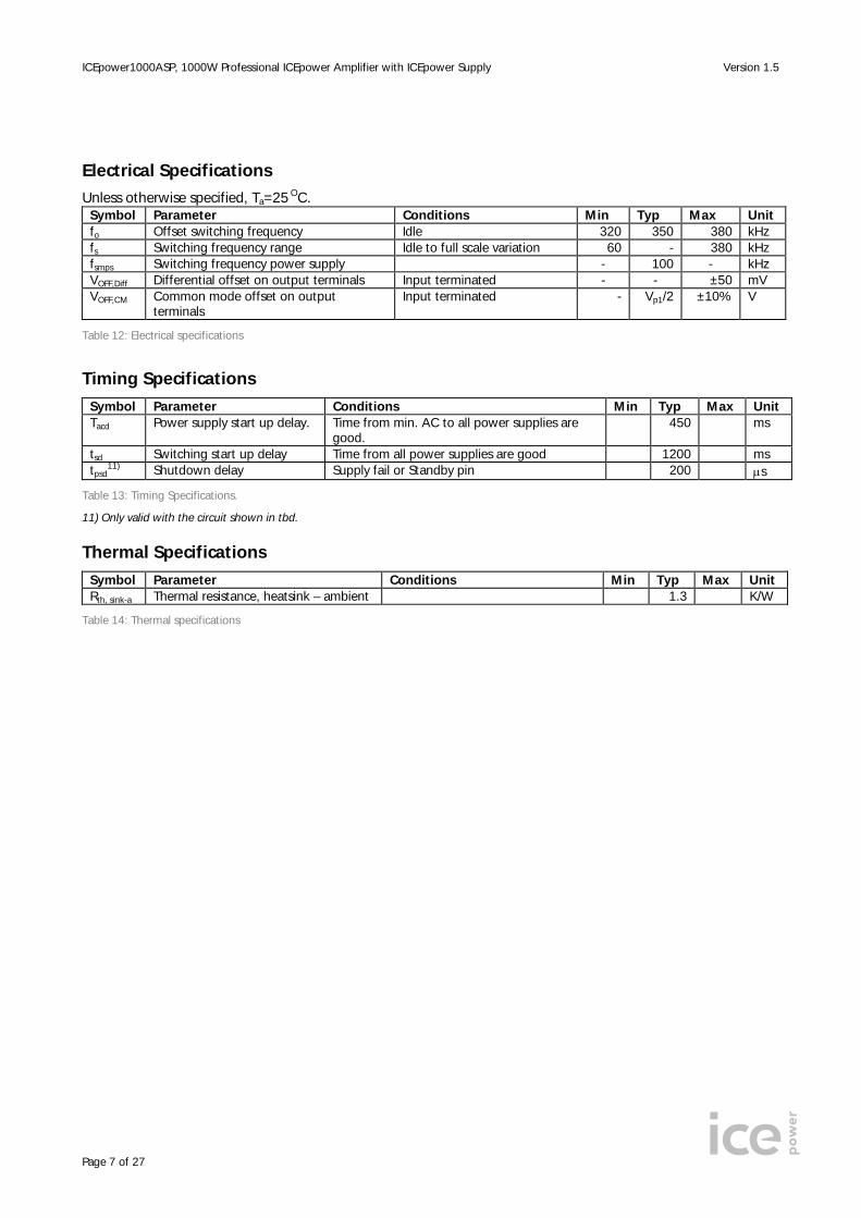
Harmonic Distortion & Noise
0.001
1
0.002
0.005
0.01
0.02
0.05
0.1
0.2
0.5
%
100m 700200m 500m 1 2 5 10 20 50 100 200Watts
THD+N vs. output power at 100Hz, 1kHz and 6.67kHz 12) (8Ω).
-160
+0
-140
-120
-100
-80
-60
-40
-20
dBr A
2k 22k4k 6k 8k 10k 12k 14k 16k 18k 20kHz
Idle noise (4Ω). (32K FFT). Residual = 80μV(A). 0dB@1000W
0.001
1
0.002
0.005
0.01
0.02
0.05
0.1
0.2
0.5
%
100m 1k200m 500m 1 2 5 10 20 50 100 200 500Watts
THD+N vs. output power at 100Hz, 1kHz and 6.67kHz 12) (4Ω).
-160
+0
-140
-120
-100
-80
-60
-40
-20
dBr A
2k 22k4k 6k 8k 10k 12k 14k 16k 18k 20kHz
f = 5kHz. Po = 100mW. 4Ω loading. 0dB@1000W
Figure 9: Total harmonic distortion & noise 12) An Audio Precision AES17 20 kHz 7th order measurement filter is used for measurements. The frequency 6.67 kHz corresponds to the worst-case situation where both 2nd and 3rd harmonics are within the audio band.

ICEpower1000ASP, 1000W Professional ICEpower Amplifier with ICEpower Supply Version 1.5
Page 13 of 27
Intermodulation Distortion (CCIF & TIM)
0.0001
1
0.0002
0.0005
0.001
0.002
0.005
0.01
0.02
0.05
0.1
0.2
0.5
%
100m 200200m 500m 1 2 5 10 20 50 100W
CCIF IMD vs. PO, RL = 4Ω, f1 =14kHz, f2 = 15kHz.
-140
+0
-120
-100
-80
-60
-40
-20
dBr A
2k 22k4k 6k 8k 10k 12k 14k 16k 18k 20kHz
CCIF IMD analysis. RL = 4Ω, PO =10W, 0dB@1000W
0.001
1
0.002
0.005
0.01
0.02
0.05
0.1
0.2
0.5
%
100m 1k200m 500m 1 2 5 10 20 50 100 200 500W
TIM vs. output power. RL = 4Ω.
-160
+0
-140
-120
-100
-80
-60
-40
-20
dBr A
2k 22k4k 6k 8k 10k 12k 14k 16k 18k 20kHz
TIM FFT analysis. RL = 4Ω, PO =10W, 0dB@1000W
Figure 10: Intermodulation distortion
ICEpower1000ASP, 1000W Professional ICEpower Amplifier with ICEpower Supply Version 1.5
Page 14 of 27
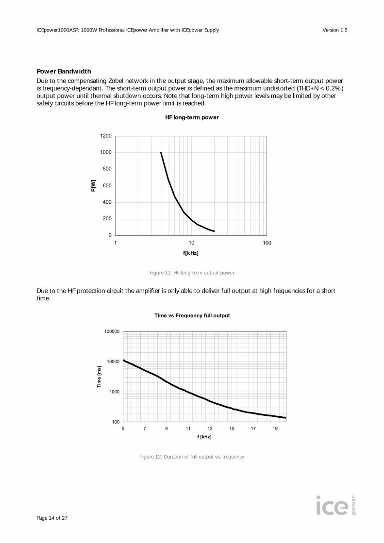
Power Bandwidth Due to the compensating Zobel network in the output stage, the maximum allowable short-term output power is frequency-dependant. The short-term output power is defined as the maximum undistorted (THD+N < 0.2%) output power until thermal shutdown occurs. Note that long-term high power levels may be limited by other safety circuits before the HF long-term power limit is reached.
HF long-term power
0
200
400
600
800
1000
1200
1 10 100
f[kHz]
P[W
]
Figure 11: HF long-term output power
Due to the HF protection circuit the amplifier is only able to deliver full output at high frequencies for a short time.
Time vs Frequency full output
100
1000
10000
100000
5 7 9 11 13 15 17 19
f [kHz]
Tim
e [m
s]
Figure 12: Duration of full output vs. frequency

ICEpower1000ASP, 1000W Professional ICEpower Amplifier with ICEpower Supply Version 1.5
Page 15 of 27
High Current Output
The amplifier protection circuit will limit the long-term stress on the amplifier output stage due to high output currents. Due to this protection circuit the amplifier is only able to deliver very high currents for a limited time.
1000ASP Time vs peek current
100
1000
10000
100000
22 24 26 28 30 32 34 36 38 40
I [Peak]
Tim
e [m
s]
Figure 13: High current vs. time (Test signal 100 Hz sine).
22A to 32A into 2 Ohm load and 34A to 40A into1 Ohm load
ICEpower1000ASP, 1000W Professional ICEpower Amplifier with ICEpower Supply Version 1.5
Page 16 of 27
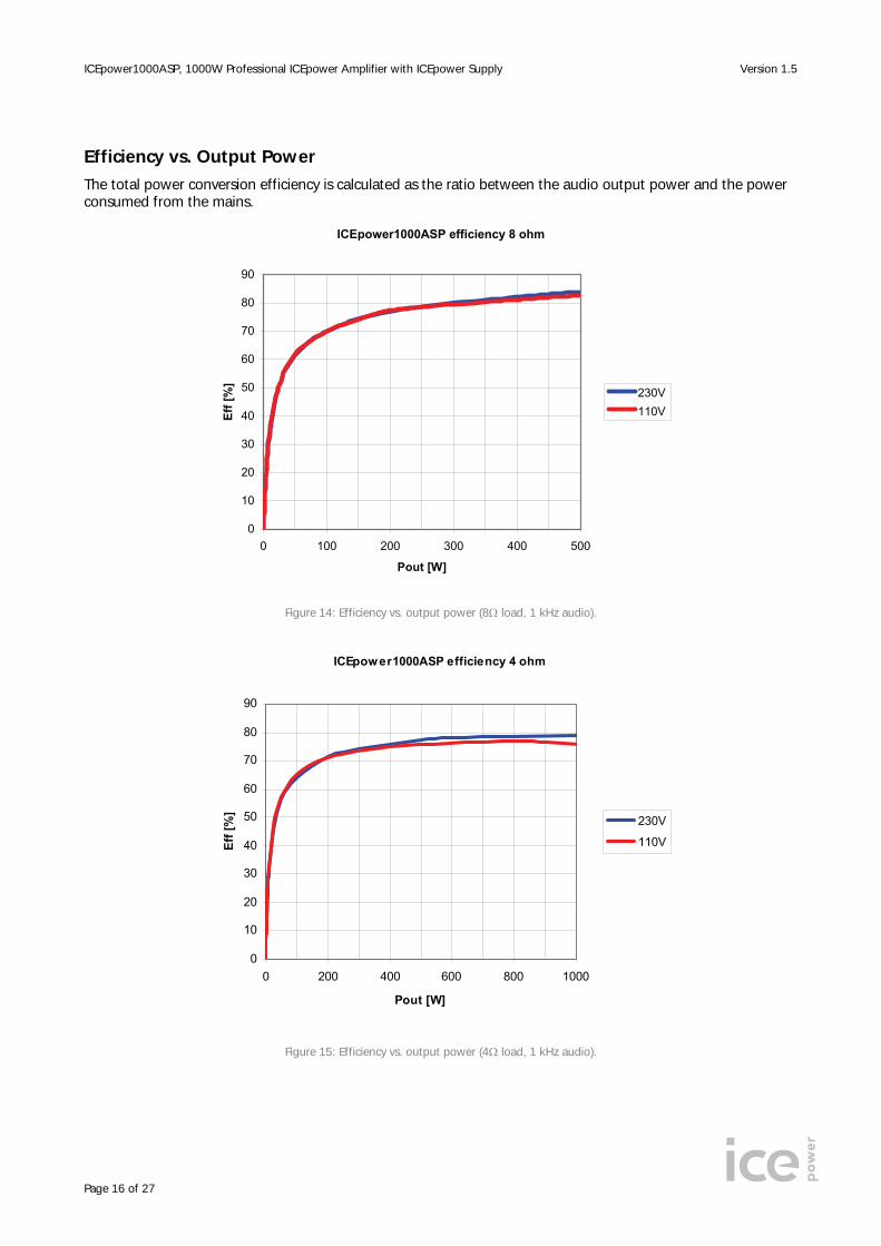
Efficiency vs. Output Power
The total power conversion efficiency is calculated as the ratio between the audio output power and the power consumed from the mains.
ICEpower1000ASP efficiency 8 ohm
0
10
20
30
40
50
60
70
80
90
0 100 200 300 400 500
Pout [W]
Eff [
%]
230V110V
Figure 14: Efficiency vs. output power (8Ω load, 1 kHz audio).
ICEpower1000ASP efficiency 4 ohm
0
10
20
30
40
50
60
70
80
90
0 200 400 600 800 1000
Pout [W]
Eff [
%]
230V
110V
Figure 15: Efficiency vs. output power (4Ω load, 1 kHz audio).
ICEpower1000ASP, 1000W Professional ICEpower Amplifier with ICEpower Supply Version 1.5
Page 17 of 27
Loading
With its low output impedance, the ICEpower1000ASP is designed to be unaffected by loudspeaker loading characteristics. However, care should be taken with purely capacitive loads. Traditionally amplifiers have been tested extensively in laboratories with purely capacitive loads. This was done to test the amplifier’s stability and performance but it does not relate to any normal speaker load as even electrostatic speakers do not present a purely capacitive load to the amplifier but include a resistive part as well. The maximum purely capacitive load allowed is 470nF.
Features
The ICEpower1000ASP has a number of useful features witch are described below.
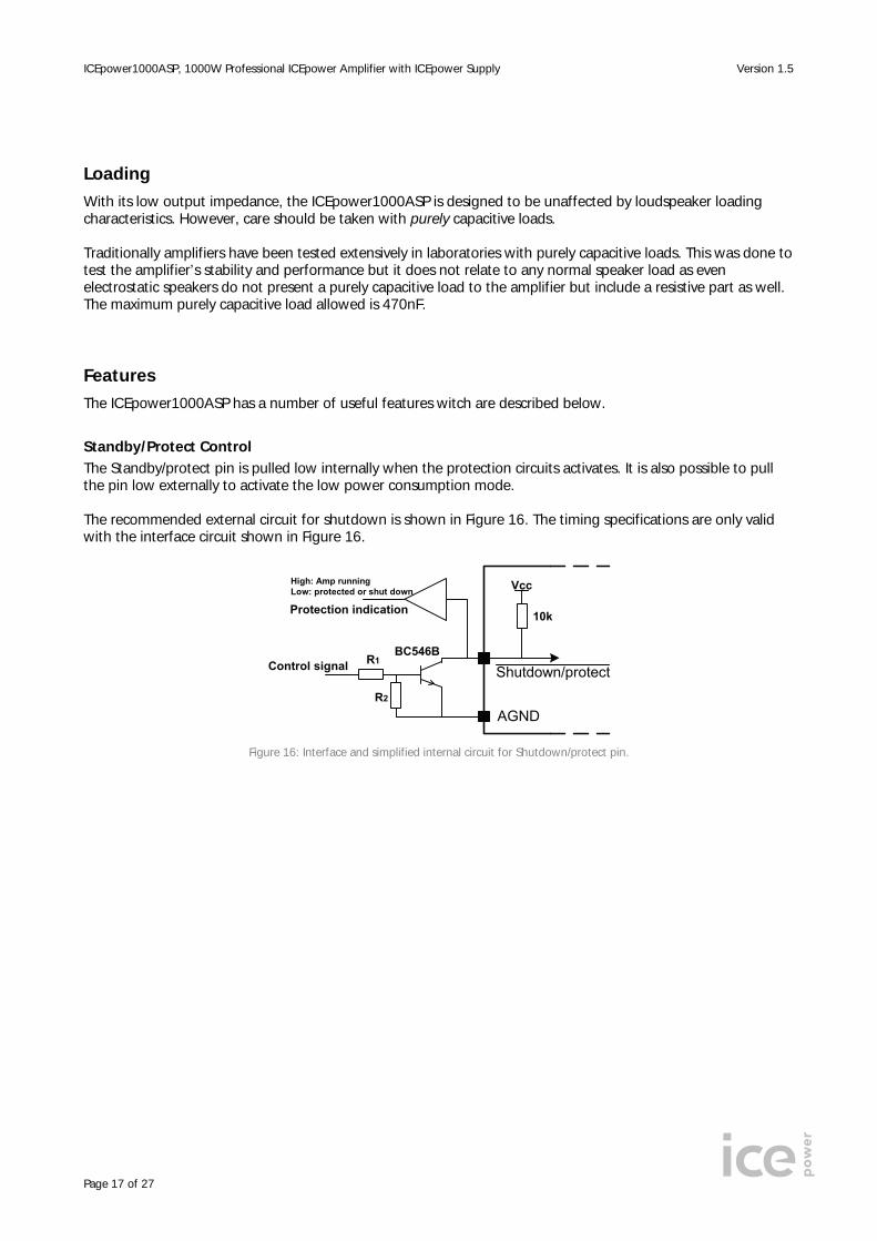
Standby/Protect Control The Standby/protect pin is pulled low internally when the protection circuits activates. It is also possible to pull the pin low externally to activate the low power consumption mode. The recommended external circuit for shutdown is shown in Figure 16. The timing specifications are only valid with the interface circuit shown in Figure 16.
AGND
Shutdown/protect
Vcc
10k
R1
R2
BC546BControl signal
Protection indication
High: Amp runningLow: protected or shut down
Figure 16: Interface and simplified internal circuit for Shutdown/protect pin.

ICEpower1000ASP, 1000W Professional ICEpower Amplifier with ICEpower Supply Version 1.5
Page 18 of 27
Vcc
Soft clip
1K
GNDA
Figure 18: Interface and simplified internal circuit for the Soft clip pin.
Monitor Output The monitor output has been implemented as an attenuated ground referenced (unbalanced) version of the balanced output signal. The internal output circuit of this output is shown in Figure 17.
47k 47k
150p
+
-
-28.3dB
Vo+ Vo-
Monitor
Internal Feedback
Figure 17: Internal circuitry of the monitor output.
The monitor output is attenuated 1.1dB in relation to the input signal and the bandwidth is limited to 45 kHz.
Soft clipping and Clipping Detection The ICEpower1000ASP is equipped with a soft clipping circuit that shapes the input signal softly and limits the maximum signal level to the output stage. The soft clipping system eliminates saturation of the control system for optimum sound performance in high-level situations. The Soft clip pin is an open collector output with a series resistor for connecting directly to an LED or external processing circuits. The internal circuit is shown in Error! Reference source not found.. Soft clip off The Soft clip off pin disables the internal soft clipping circuit when pulled low. This allows for use of external clipping circuits to suit the application without interference from the internal circuit. Even with the Soft clip off pin set to low the protection features still activate the internal circuit.

ICEpower1000ASP, 1000W Professional ICEpower Amplifier with ICEpower Supply Version 1.5
Page 19 of 27
Protection Features
The ICEpower1000ASP is equipped with professional protection features for surviving in the rough professional audio environment without damage and without compromising the audio quality. Generally the protection circuits are designed with the philosophy of “audio all time” in mind and therefore all protection circuits are self-resetting. The only circuit that does not reset is the ‘HF on output’ circuit that only activates in case of a failure or large capacitive load.
Output stage
Disable pinClip LED (red)and Clip pin
SMPS
Over current(amplifier)
Input clipping
Overtemperature
(SMPS)
Overtemperature(amplifier)
Low outputstage voltage
Input signal
Mains
Output filteroverload
HF onoutput
detection
Over current(SMPS)
Figure 19: Block diagram of protection features
Over current Protection The over current protection is designed with two states. The first state limits the output current to the protection level of 40A. This level of current is allowed for a short period of time, but if the output current remains too high, state two is activated. State two disables the amplifier for the same amount of time as if a power failure had occurred. The amplifier will restart when the cause of the overload has been removed, and in case of short overloads, the music will continue playing. Thermal Protection The ICEpower1000ASP is equipped with two thermal protection circuits. The first monitors the temperature of the power supply and attenuates the output voltage if the temperature exceeds the limit. The other protection circuit monitors the amplifier temperature and shuts down the amplifier if the temperature becomes too high. Both protection circuits are self-resetting once the temperature has dropped to an acceptable level.
Overload Protection
In case of high-amplitude continuous low frequency signals in loads lower than 4Ω the power supply may not be able to deliver the required amount of power to the amplifier and the supply voltage will drop. The overload protection circuit will then lower the threshold of the input soft clipping circuit until the output power has been reduced to an acceptable level. As a result the amplifier will not shut down because of under voltage and the music will still be playing but with a softly shaped audio signal.
Long-term HF Protection The output filter of the amplifier is not capable of handling large long-term high frequency signals due to the Zobel-network. This protection circuit decreases the threshold of the soft clipping circuit to limit the input signal in case of overload. Consequently, damage to the Zobel-network (or a high frequency driver) should not occur even under laboratory tests or any other condition that is not music (e.g. microphone feedback). The ICEpower1000ASP has been tested at extreme music levels with the most demanding music without triggering the high frequency protection circuit.

ICEpower1000ASP, 1000W Professional ICEpower Amplifier with ICEpower Supply Version 1.5
Page 20 of 27
Input/Output Interfaces
Input Stage The balanced input section on the ICEpower1000ASP provides signal buffering and anti-aliasing filtering. The balanced configuration helps to avoid hum and noise pick-up in poorly shielded cables. An unbalanced input can be set (without affecting the overall gain) by applying a short between Vi- and AGND.
+
-Vi-
Vi+
1k
1k
3k3
3k3
C1 C16k8
6k8
AGND
Figure 20: Balanced input buffer.
The input impedance of the signal input section is approximately 8kΩ over the audio bandwidth, which is an acceptable loading condition for most pre-amps, active crossover outputs etc.
Output Stage The output stage is a full bridge topology with a 2nd order filter meaning the power output on the terminals Vo+ and Vo- is balanced. The output filter design is a part of ICEpower’s proprietary MECC topology and has been chosen as a compromise between demodulation characteristics, efficiency and filter compactness.
PowerStage
Vo+
Vo-L
L
C
CZ
RZ
ICEpower1000ASP
Output filter
Figure 21: Output filter section with compensating Zobel network.
The essential output characteristics are: • The switching residual on the output primarily consists of a single frequency component at the carrier
fundamental fs. • The system bandwidth is 38 kHz in 8Ω. Warning! The balanced speaker outputs are both “hot” with a common-mode DC level equal to Vp/2. Balanced probes should always be used for monitoring and measurements.
ICEpower1000ASP, 1000W Professional ICEpower Amplifier with ICEpower Supply Version 1.5
Page 21 of 27
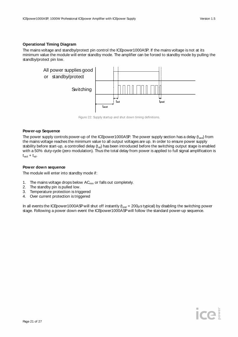
Operational Timing Diagram The mains voltage and standby/protect pin control the ICEpower1000ASP. If the mains voltage is not at its minimum value the module will enter standby mode. The amplifier can be forced to standby mode by pulling the standby/protect pin low.
All power supplies goodor standby/protect
Switching
tacd
tsd tpsd
Figure 22: Supply startup and shut down timing definitions.
Power-up Sequence The power supply controls power-up of the ICEpower1000ASP. The power supply section has a delay (tacd) from the mains voltage reaches the minimum value to all output voltages are up. In order to ensure power supply stability before start-up, a controlled delay (tsd) has been introduced before the switching output stage is enabled with a 50% duty-cycle (zero modulation). Thus the total delay from power is applied to full signal amplification is tacd + tsd.
Power down sequence The module will enter into standby mode if: 1. The mains voltage drops below ACmin or falls out completely. 2. The standby pin is pulled low. 3. Temperature protection is triggered 4. Over current protection is triggered In all events the ICEpower1000ASP will shut off instantly (tpsd = 200μs typical) by disabling the switching power stage. Following a power down event the ICEpower1000ASP will follow the standard power-up sequence.
ICEpower1000ASP, 1000W Professional ICEpower Amplifier with ICEpower Supply Version 1.5
Page 22 of 27
Thermal Design
Thermal design is generally a great challenge in power amplifier systems. Linear amplifier designs operating in class A or AB are normally very inefficient and therefore equipped with extensive heat sinking to keep the transistor junction temperature low. The ICEpower1000ASP is based on highly efficient ICEpower switching technology providing high overall efficiency characteristics at all levels of operation. Part of the “component” philosophy of the ASP–series is to provide a self-cooled component thus eliminating the need for special attention to thermal design. The ICEpower1000ASP is designed for music reproduction, which means that the output power of the amplifier will never be continuous. If the average power exceeds 85W @ 4Ω (typical) for a long time at 25°C ambient temperature, the module will reach its maximum allowable temperature and the temperature protection will be activated. At 50°C ambient temperature more than 40W @ 4Ω (typical) average power will activate the temperature protection. For extreme loading requirements with a high continuous average loading or ambient temperatures above 40°C, we recommend the use of an external heat sink, which will improve the FTC power rating. Further information is located in the ICEpower ASP Designer’s Manual.
Fuses
The ICEpower250ASP has been safety approved using the following fuses 115V Mains: T10AH 125V Wickmann/Littlefuse series 181 or series 215 230V Mains: T6.3AH 250V Wickmann/Littlefuse series 181 or series 215 T: time-lag H: high-breaking 5*20mm, according to IEC60127-2/5 and UL248.14 High-breaking capability (1500A) fuses are used for safety reasons and to allow powering up more than 30000 times. Fuses from different vendors are not guaranteed to be alike and in any case the module is only safety approved with the above-mentioned fuses. The ICEpower1000ASP is fitted with the fuse suitable for 230V use (and with the voltage selector set to 230V) on delivery as this is the safest setup for protecting the module for global use. To use the ICEpower1000ASP in 100V/115V areas, please replace the factory mounted fuse with appropriate type for 115V mains and mount the fuse in the 115V position as indicated on the board.

ICEpower1000ASP, 1000W Professional ICEpower Amplifier with ICEpower Supply Version 1.5
Page 23 of 27
Physical Dimensions
Figure 23: Physical dimensions in mm.
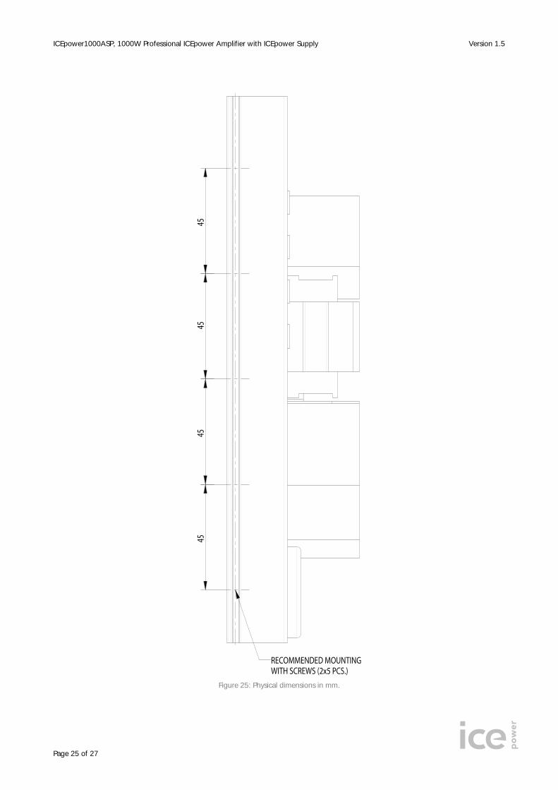
Important! A minimum clearance of 12 mm. above the module is required for safety and ventilation reasons.

ICEpower1000ASP, 1000W Professional ICEpower Amplifier with ICEpower Supply Version 1.5
Page 24 of 27
Figure 24: Physical dimensions in mm.
ICEpower1000ASP, 1000W Professional ICEpower Amplifier with ICEpower Supply Version 1.5
Page 25 of 27
Figure 25: Physical dimensions in mm.

ICEpower1000ASP, 1000W Professional ICEpower Amplifier with ICEpower Supply Version 1.5
Page 26 of 27
Safety Standards
The ICEpower250ASP has been pre-approved for safety by CSA to ease the design-in procedure and complies with the following standards: Europe: IEC60065 6th ed. (1998) US: UL6500 2nd ed. CA: E60065 6th ed. The following chapters apply to the product: §7, 10, 11, 13, 14, 15 and 20
Safety class Class 1 (with earth)
ESD Warning
Bang & Olufsen ICEpower products are manufactured according to the following ESD precautions:
• IEC 61340-5-1: Protection of electronic devices from electrostatic phenomena. General Requirements. • IEC 61340-5-2: Protection of electronic devices from electrostatic phenomena. User Guide. • ANSI/ESD-S20.20-1999: Protection of Electrical and Electronic Parts, Assemblies and Equipment.
Further handling of the products should comply with the same standards. The general guarantee policy of Bang & Olufsen ICEpower a/s does not cover ESD damaged products due to improper handling.
Packaging and Storing
The ICEpower1000ASP is delivered on pallets of 80 units. Each pallet has 5 x 2 cartons, each with 8 units.
Dimensions and Weight
Dimensions (W x L x H) [cm] Weight [kgs] Carton 57 x 35 x 18 15.3 Pallet 80 x 60 x 105 160 ESD safe cardboard is used for wrapping.
Storage Humidity Do not expose the pallets to rain or humidity levels higher than 85%.
Storage Temperature The pallets are to be stored at temperatures from 0°C to 70°C.
Stacking Pallets may not be stacked on top of each other.

ICEpower1000ASP, 1000W Professional ICEpower Amplifier with ICEpower Supply Version 1.5
Page 27 of 27
Notes For additional information about the ICEpower® technology from Bang & Olufsen ICEpower a/s, visit our web site or contact us. Bang & Olufsen ICEpower a/s Gl. Lundtoftevej 1b DK-2800 Kgs. Lyngby Denmark Phone +45 45203600 Fax +45 45203699 Website http://www.ICEpower.bang-olufsen.com E-mail [email protected] Notice The data sheet contains specifications that may be subject to change without prior notice. ICEpower® is a trademark of Bang & Olufsen ICEpower a/s. Bang & Olufsen ICEpower a/s products are not authorized for use as critical components in life support devices or systems without the express written approval of the president and general counsel of Bang & Olufsen ICEpower a/s. As used herein:
1. Life support devices or systems are devices or systems which, (a) are intended for surgical implant into the body, or (b) support or sustain life, and whose failure to perform when properly used in accordance with instructions for use provided in the labeling, can be reasonably expected to result in a significant injury to the user.
2. A critical component is any component of a life support device or system whose failure to perform can
be reasonably expected to cause the failure of the life support device or system, or to affect its safety or effectiveness.