Embed Size (px)
Citation preview

8/10/2019 Icemcfd Tips&Tricks2010
http://slidepdf.com/reader/full/icemcfd-tipstricks2010 1/117
© 2010 ANSYS, Inc. All rights reserved. 1 ANSYS, Inc. Proprietary
© 2010 ANSYS, Inc. All rights reserved. 1 ANSYS, Inc. Proprietary
ICEM CFD
Tips and Tricks2010…
ICEM CFD
Tips and Tricks2010…
SimonPereira
8/10/2019 Icemcfd Tips&Tricks2010
http://slidepdf.com/reader/full/icemcfd-tipstricks2010 2/117
© 2010 ANSYS, Inc. All rights reserved. 2 ANSYS, Inc. Proprietary
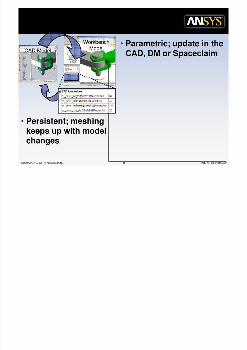
Guiding principles of Workbench
CAD Model
WorkbenchModel
Thisimagecann otcurrently bedisplayed.
• Parametric; update in theCAD, DM or Spaceclaim
• Persistent; meshingkeeps up with modelchanges

8/10/2019 Icemcfd Tips&Tricks2010
http://slidepdf.com/reader/full/icemcfd-tipstricks2010 3/117
© 2010 ANSYS, Inc. All rights reserved. 3 ANSYS, Inc. Proprietary
Guiding principles of Workbench
• Highly-automated
– Physics aware
intelligent defaults
– Context sensitivemeshing (prism,
contact, etc.)
Automatic Contact(FEA),
Non-conformalinterfaces (CFD), etc.
Automated Meshing
Apply loads on geometryGo straight to solution!

8/10/2019 Icemcfd Tips&Tricks2010
http://slidepdf.com/reader/full/icemcfd-tipstricks2010 4/117
© 2010 ANSYS, Inc. All rights reserved. 4 ANSYS, Inc. Proprietary
Guiding principles of Workbench
• Flexibility:
– Breadth of mesh
methods/controls– Depth of
basic/advanced tools
Hex-Dominant
Tet
Swept
Free Mesh Type = Tetra
Free Mesh Type = Hexa Dominant
Free Mesh Type = Hexa Core

8/10/2019 Icemcfd Tips&Tricks2010
http://slidepdf.com/reader/full/icemcfd-tipstricks2010 5/117
© 2010 ANSYS, Inc. All rights reserved. 5 ANSYS, Inc. Proprietary
Workbench IntegratedMeshing
►Sold as part of integrated solver
solution►Can Add additional dedicatedseats
The Future of Meshing
►Combination of best in classtechnologies and concepts
►Integrated in a user friendlysimulation environment
►For all Physics (CFD, FEA, etc.)
Workbench Guiding Principles
►Parametric and Persistent
►Highly Automated, Physics Aware
►
Flexible Controls►Adaptive Architecture
CFD with“programcontrolled
” inflation
!"#" Meshing
GAMBIT
CFX-Mesh
ANSYS MAPDL
ICEM CFD
TGrid
Supports instances
FEA
Combine
meshmethods

8/10/2019 Icemcfd Tips&Tricks2010
http://slidepdf.com/reader/full/icemcfd-tipstricks2010 6/117
© 2010 ANSYS, Inc. All rights reserved. 6 ANSYS, Inc. Proprietary
E x t e n d e d
F u n
c t i o n a l i t y
Mesh from
►Facets and/or Mesh
►Poor or complex data
Efficiently Mesh large/complex models
►Greater than 20 million cells
►Extended mesh controls
Advanced Mesh options
►Intelligent automated Prism
►HexCore to far-field planes
►
Wrapper technology►GoCart technology
Extended mesh diagnostics
Interactive Mesh Editing
►Remeshing, etc.
ComplexGeometry
AdvancedCartesian Hexa
Core and Inflation
Cavity
Re-meshing
Testdrive
GoCart
now!
!"#" TGrid E$%ends !"#" Meshing
Capabili%ies Wi%h &o'er To(
Wrap anyComplexGeometry
8/10/2019 Icemcfd Tips&Tricks2010
http://slidepdf.com/reader/full/icemcfd-tipstricks2010 7/117
© 2010 ANSYS, Inc. All rights reserved. 7 ANSYS, Inc. Proprietary
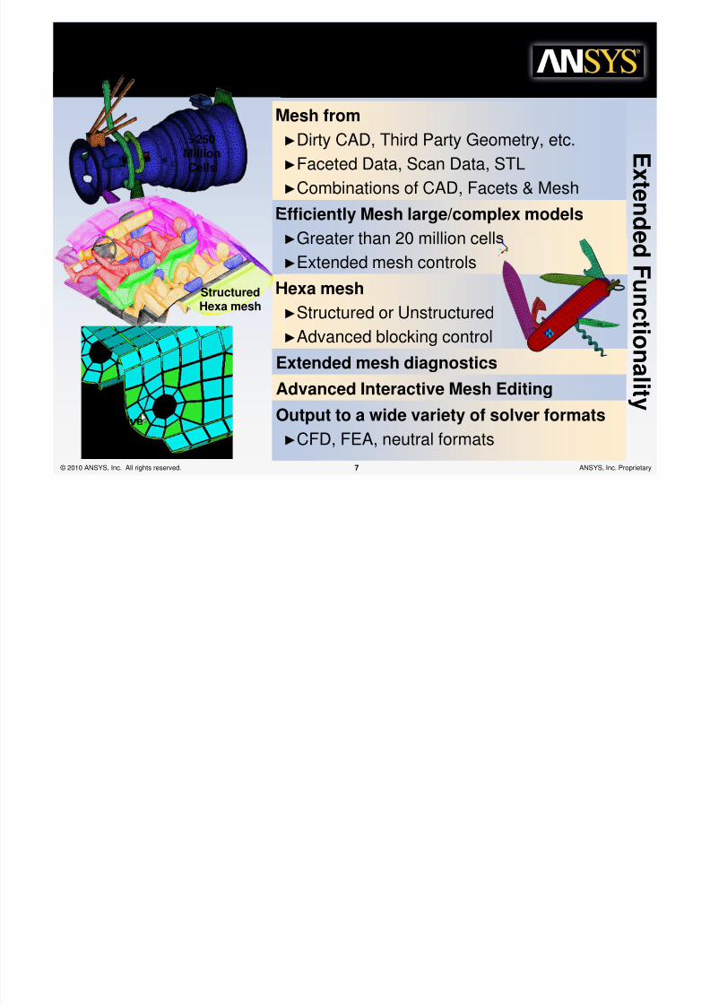
Mesh from
►Dirty CAD, Third Party Geometry, etc.
►Faceted Data, Scan Data, STL
►Combinations of CAD, Facets & Mesh
E
x t en d e d
F un c t i on al i t y
Efficiently Mesh large/complex models
►Greater than 20 million cells
►Extended mesh controlsHexa mesh
►Structured or Unstructured
►Advanced blocking control
Extended mesh diagnostics
Advanced Interactive Mesh Editing
Output to a wide variety of solver formats
►CFD, FEA, neutral formats
StructuredHexa mesh
>250MillionCells
Interactive
MeshEditing
!"#" ICEM CFD E$%ends !"#"
Meshing Capabili%ies Wi%h &o'er To(

8/10/2019 Icemcfd Tips&Tricks2010
http://slidepdf.com/reader/full/icemcfd-tipstricks2010 8/117
© 2010 ANSYS, Inc. All rights reserved. 8 ANSYS, Inc. Proprietary © 2010 ANSYS, Inc. All rights reserved. 8 ANSYS, Inc. Proprietary
ICEM CFD Tips andTricks 12)1ICEM CFD Tips andTricks 12)1
Simon PereiraSimon Pereira

8/10/2019 Icemcfd Tips&Tricks2010
http://slidepdf.com/reader/full/icemcfd-tipstricks2010 9/117
© 2010 ANSYS, Inc. All rights reserved. 9 ANSYS, Inc. Proprietary
genda
• Tips and Tricks
– General, Tetra/Prism– Hexa
8/10/2019 Icemcfd Tips&Tricks2010
http://slidepdf.com/reader/full/icemcfd-tipstricks2010 10/117
© 2010 ANSYS, Inc. All rights reserved. 10 ANSYS, Inc. Proprietary
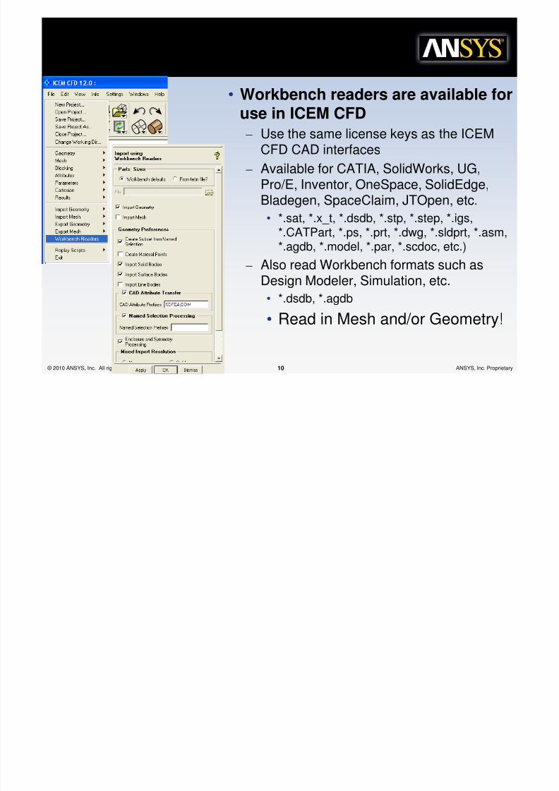
Workbench *eaders
• Workbench readers are available foruse in ICEM CFD
– Use the same license keys as the ICEMCFD CAD interfaces
– Available for CATIA, SolidWorks, UG,Pro/E, Inventor, OneSpace, SolidEdge,Bladegen, SpaceClaim, JTOpen, etc.
• *.sat, *.x_t, *.dsdb, *.stp, *.step, *.igs,*.CATPart, *.ps, *.prt, *.dwg, *.sldprt, *.asm,*.agdb, *.model, *.par, *.scdoc, etc.)
– Also read Workbench formats such as
Design Modeler, Simulation, etc.• *.dsdb, *.agdb
• Read in Mesh and/or Geometry!

8/10/2019 Icemcfd Tips&Tricks2010
http://slidepdf.com/reader/full/icemcfd-tipstricks2010 11/117
© 2010 ANSYS, Inc. All rights reserved. 11 ANSYS, Inc. Proprietary
I+por% geo+e%r, using
Workbench *eaders• You can import Geometry from Workbench Design
Modeler
– Only active bodies are imported (Bone Marrow was not
active)– Named selections are imported
• Create Subset from Named Selection
– Named Selections can be setup in DM, Simulation orCAD packages such as UG, Pro/E or SolidWorks
– SpaceClaim too! – Option to filter by “Named Selection Prefixes”
• Accept the Defaults and apply
1
2
3
Often easier to do CAD creation,
simplification or repair in WorkbenchDesign modeler and transfer thedata to ICEM CFD

8/10/2019 Icemcfd Tips&Tricks2010
http://slidepdf.com/reader/full/icemcfd-tipstricks2010 12/117
© 2010 ANSYS, Inc. All rights reserved. 12 ANSYS, Inc. Proprietary
!a+ed "elec%ions as "ubse%s
• Each Body comes in as a Part
• The named Selections can appear as Geometry Subsets
– These can be used to control display or selection
– These can be turned into Parts
• Make sure all the Subsets are active
• Right Click on “Subsets” and choose “Create Part
• The new parts can be displayed
1
2
8/10/2019 Icemcfd Tips&Tricks2010
http://slidepdf.com/reader/full/icemcfd-tipstricks2010 13/117
© 2010 ANSYS, Inc. All rights reserved. 13 ANSYS, Inc. Proprietary
*epair Geo+e%r,
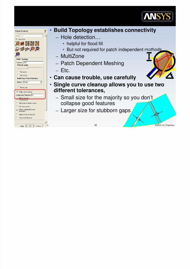
• Build Topology establishes connectivity
– Hole detection…• helpful for flood fill
• But not required for patch independent methods
– MultiZone
– Patch Dependent Meshing
– Etc.• Can cause trouble, use carefully
• Single curve cleanup allows you to use twodifferent tolerances,
– Small size for the majority so you don’tcollapse good features
– Larger size for stubborn gaps

8/10/2019 Icemcfd Tips&Tricks2010
http://slidepdf.com/reader/full/icemcfd-tipstricks2010 14/117
© 2010 ANSYS, Inc. All rights reserved. 14 ANSYS, Inc. Proprietary
*epair Geo+e%r,
• Once Diagnostic Topology is built options such as Floodfill and feature detection become available

8/10/2019 Icemcfd Tips&Tricks2010
http://slidepdf.com/reader/full/icemcfd-tipstricks2010 15/117
© 2010 ANSYS, Inc. All rights reserved. 15 ANSYS, Inc. Proprietary
*epair Geo+e%r,
• Detection tools have obvious use
for extracting, selecting and even
removing features– Hole tool has advanced options to
remove holes or set sizes for patchbased surface meshing
– Fillet tool is usefull for putting fillets ina different subset or part so you canapply a different meshing method
• But what about nasty models where Build topology can’t
help or causes more trouble then it is worth?

8/10/2019 Icemcfd Tips&Tricks2010
http://slidepdf.com/reader/full/icemcfd-tipstricks2010 16/117
© 2010 ANSYS, Inc. All rights reserved. 16 ANSYS, Inc. Proprietary
*epair Geo+e%r, -'.o /uild Topo
• The Check Geometry option does *surface based* featuredetection (not topology based)
• If you have a scary model, such as a large complex castengine block,
– don’t build topology, it may take too long or cause trouble.– delete all the curves and points– extract all the flat items to a new part
• Low curvature
– Extract points and curves from the flat parts– Complete parameter setup and proceed to Octree tetra…
Area andNormal canhelp filterprecisely

8/10/2019 Icemcfd Tips&Tricks2010
http://slidepdf.com/reader/full/icemcfd-tipstricks2010 17/117
© 2010 ANSYS, Inc. All rights reserved. 17 ANSYS, Inc. Proprietary
o%ke,s
• Hotkeys can make you much more efficient
• Search the Help to get hotkey maps•There is consistency tothe hotkeys
•For instance “s” is forsplit.
•On the geometrypanel, it is splitcurve.
•On the Mesh EditPanel, it is for SplitEdge
•Control-hotkey is aspecial ability, such ascontrol-s for splitw/propagate
•Shift-hokey is an alternate
•“?” to list hotkeys
Hotkeys are Tab specific

8/10/2019 Icemcfd Tips&Tricks2010
http://slidepdf.com/reader/full/icemcfd-tipstricks2010 18/117
© 2010 ANSYS, Inc. All rights reserved. 18 ANSYS, Inc. Proprietary
*e+inder abou% c%ree "i3es
• With Octree, it is important to understand mesh size…– Many long time users waste time setting wrong sizes
• Sizes carefully set to 0.75, 0.5 and some 0.3
• Max deviation set to 0.05 and Min size set to 0.45…
• The 0.75 and 0.5 both round downto 0.5.
• The smaller 0.3 would round down to0.25, but since it is sill much largerthan the small detail it is placed on,why no just set the entire part to 0.5
• The Min Size rounds down to 0.25
– Since this is the smallest size set, allother sizes are related to this size
– Local Size = (Smallest Size)*2n forn=0 to ∞

8/10/2019 Icemcfd Tips&Tricks2010
http://slidepdf.com/reader/full/icemcfd-tipstricks2010 19/117
© 2010 ANSYS, Inc. All rights reserved. 19 ANSYS, Inc. Proprietary
Densi%, regions…
• A density region sets the Max local size within the volume
– Use with Geometry Translation tool to copy/translate/rotate
– Use line and point densities when advantageous
– Use Width on surfaces to refine near the wall

8/10/2019 Icemcfd Tips&Tricks2010
http://slidepdf.com/reader/full/icemcfd-tipstricks2010 20/117
© 2010 ANSYS, Inc. All rights reserved. 20 ANSYS, Inc. Proprietary
Working 'i%h Densi%, regions
• More here about various density types, show
how to create a cone and a torus.

8/10/2019 Icemcfd Tips&Tricks2010
http://slidepdf.com/reader/full/icemcfd-tipstricks2010 21/117
© 2010 ANSYS, Inc. All rights reserved. 21 ANSYS, Inc. Proprietary
Edge Cri%erion 4 Thin Cu%s
– Edge Criterion• Determines if a node projects to surface or the edge is
split
• Range from 0 to 1– 0.2 ok for most cases.
• To increase nodes moving to fit to geometry, increasethis criterion
– Ideal for planned tet to hex conversion
• To increase refinement near entities, reduce this– Reduces non manifold verts in trailing edges
Edge Criterion = 0.2
Edge Criterion = 0.01Handy when thin cuts failor are difficult to setup

8/10/2019 Icemcfd Tips&Tricks2010
http://slidepdf.com/reader/full/icemcfd-tipstricks2010 22/117
© 2010 ANSYS, Inc. All rights reserved. 22 ANSYS, Inc. Proprietary
Edge Cri%erion 4 Thin Cu%s
– Define Thin cuts• Tool for resolving gaps based on pairs
of parts.
• It is made necessary by the octreeprocess– One way to avoid the problem is to use
patch based meshing
• Thin cuts have limits
– If two surfaces approach asymptotically,this may eventually break down
– If the separation rule of thin cuts isviolated at any point, all thin cuts aredeactivated
B
A
c
If the face of a tetra elementhas a surface/line node onpart “A” then it may nothave a surface/line node in
part “B ”
Note; If the surfaces of thetwo parts, A and B , meet,then the contact curvemust be in a third part, c , orthe thin cut will fail.

8/10/2019 Icemcfd Tips&Tricks2010
http://slidepdf.com/reader/full/icemcfd-tipstricks2010 23/117
© 2010 ANSYS, Inc. All rights reserved. 23 ANSYS, Inc. Proprietary
Ignore Wall Thickness
• You don’t always want thin gaps refined
• FEA – higher Aspect Ratio
• CFD – ignore wall thickness
Off
On
FEA CFD

8/10/2019 Icemcfd Tips&Tricks2010
http://slidepdf.com/reader/full/icemcfd-tipstricks2010 24/117
© 2010 ANSYS, Inc. All rights reserved. 24 ANSYS, Inc. Proprietary
ccurac,
• The mesh projection module inICEM CFD facets b-spline
surfaces and curves• Tri tolerance determines the
degree of facetization, accuracy
Tri t olerance = 0.1
Facetizedbehind thescenes

8/10/2019 Icemcfd Tips&Tricks2010
http://slidepdf.com/reader/full/icemcfd-tipstricks2010 25/117
© 2010 ANSYS, Inc. All rights reserved. 25 ANSYS, Inc. Proprietary
ccurac,
Lower tri tolerance = more precise curvature
Greater accuracy
Slower Rendering
Tri tolerance =0.1 Tri tolerance =0.01
Increase tri tolerance to work on large models, but put it
back at the default when computing the meshTri tolerance =0.001
(default)
8/10/2019 Icemcfd Tips&Tricks2010
http://slidepdf.com/reader/full/icemcfd-tipstricks2010 26/117
© 2010 ANSYS, Inc. All rights reserved. 26 ANSYS, Inc. Proprietary
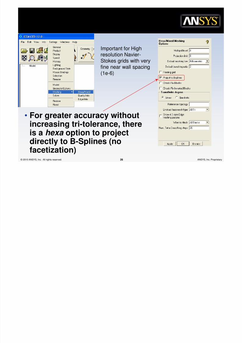
ccurac,
• For greater accuracy withoutincreasing tri-tolerance, thereis a hexa option to projectdirectly to B-Splines (no
facetization)
Important for Highresolution Navier-
Stokes grids with veryfine near wall spacing(1e-6)

8/10/2019 Icemcfd Tips&Tricks2010
http://slidepdf.com/reader/full/icemcfd-tipstricks2010 27/117
© 2010 ANSYS, Inc. All rights reserved. 27 ANSYS, Inc. Proprietary
"urface Mesh T,pe
• Mesh Type• Mesh Method
– Transitions between mesh methods andtypes are handled automatically
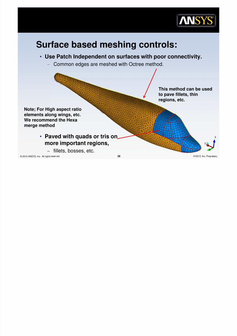
Surface based meshing controls:
Set different mesh methodsor types for each surface?
Mapped/paved bosses,patch independent tetra
everywhere else?
8/10/2019 Icemcfd Tips&Tricks2010
http://slidepdf.com/reader/full/icemcfd-tipstricks2010 28/117
© 2010 ANSYS, Inc. All rights reserved. 28 ANSYS, Inc. Proprietary
!"#" ICEM CFD De5elop+en%
• Use Patch Independent on surfaces with poor connectivity.
– Common edges are meshed with Octree method.
• Paved with quads or tris onmore important regions,
– fillets, bosses, etc.
Surface based meshing controls:
Note; For High aspect ratioelements along wings, etc.
We recommend the Hexamerge method
This method can be usedto pave fillets, thinregions, etc.
8/10/2019 Icemcfd Tips&Tricks2010
http://slidepdf.com/reader/full/icemcfd-tipstricks2010 29/117
© 2010 ANSYS, Inc. All rights reserved. 29 ANSYS, Inc. Proprietary
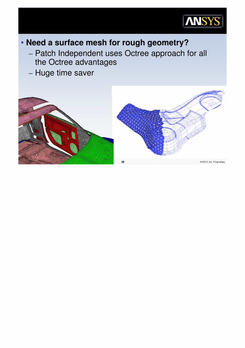
&a%ch Independen% "urface Meshing
• Need a surface mesh for rough geometry?
– Patch Independent uses Octree approach for all
the Octree advantages– Huge time saver

8/10/2019 Icemcfd Tips&Tricks2010
http://slidepdf.com/reader/full/icemcfd-tipstricks2010 30/117
© 2010 ANSYS, Inc. All rights reserved. 30 ANSYS, Inc. Proprietary
e$a for "urface +eshing
• It is a little more work, but for stamped parts, Hexamay be well worth while.
• Controlled wrapping
Just use Remesh tofix any difficult
areas
8/10/2019 Icemcfd Tips&Tricks2010
http://slidepdf.com/reader/full/icemcfd-tipstricks2010 31/117
© 2010 ANSYS, Inc. All rights reserved. 31 ANSYS, Inc. Proprietary
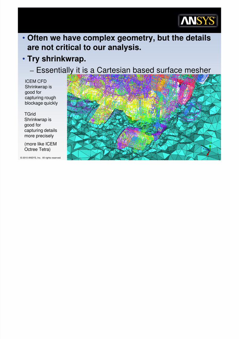
Co+ple$ Geo+e%r,
• Often we have complex geometry, but the detailsare not critical to our analysis.
• Try shrinkwrap.– Essentially it is a Cartesian based surface mesher
ICEM CFDShrinkwrap is
good forcapturing roughblockage quickly
TGrid
Shrinkwrap isgood forcapturing detailsmore precisely
(more like ICEM
Octree Tetra)

8/10/2019 Icemcfd Tips&Tricks2010
http://slidepdf.com/reader/full/icemcfd-tipstricks2010 32/117
© 2010 ANSYS, Inc. All rights reserved. 32 ANSYS, Inc. Proprietary
/o%%o+ 6p Te%ra +e%hods
• Use these methods in conjunction with the other ICEMCFD methods
– “top down” or “patch independent” tetra
– Patch based surface meshing
• Each method has its own specific requirements/Benefits
– All require a closed outer volume (no single edges).
• Run all the checks on the surface mesh• Internal single edges are ok (baffles)
– No sudden changes either along a surface or across agap• use Laplace smooth to prep the surface
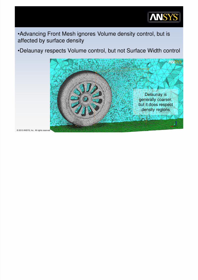
– Advancing Front mesher only works with all Tris
8/10/2019 Icemcfd Tips&Tricks2010
http://slidepdf.com/reader/full/icemcfd-tipstricks2010 33/117

8/10/2019 Icemcfd Tips&Tricks2010
http://slidepdf.com/reader/full/icemcfd-tipstricks2010 34/117
© 2010 ANSYS, Inc. All rights reserved. 34 ANSYS, Inc. Proprietary
ICEM Te%ra Meshing
Octree
Expansion Ratio=1.2
Delaunay
Advancing Front
Mix and Matchwith Hexa Core or
Prism
8/10/2019 Icemcfd Tips&Tricks2010
http://slidepdf.com/reader/full/icemcfd-tipstricks2010 35/117
© 2010 ANSYS, Inc. All rights reserved. 35 ANSYS, Inc. Proprietary
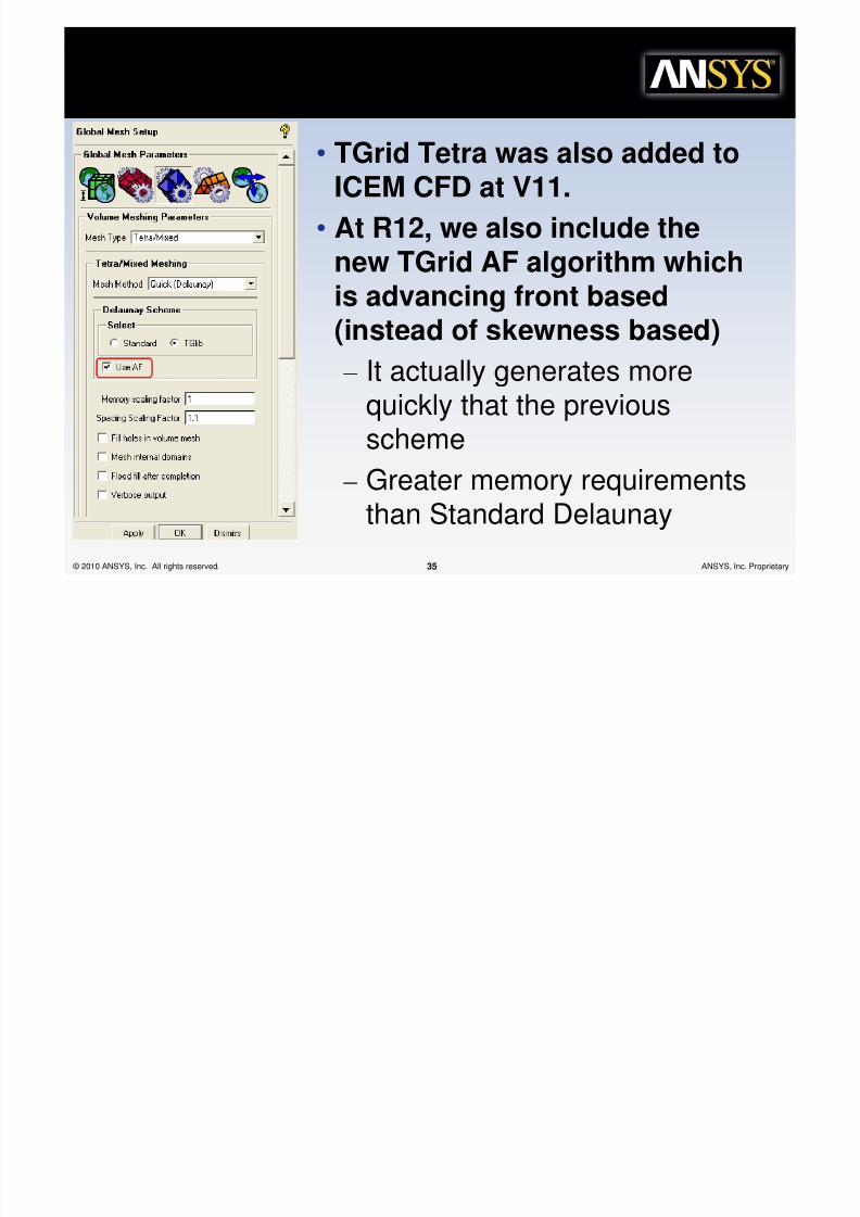
TGrid Te%ra
• TGrid Tetra was also added toICEM CFD at V11.
• At R12, we also include thenew TGrid AF algorithm whichis advancing front based
(instead of skewness based)– It actually generates more
quickly that the previous
scheme
– Greater memory requirements
than Standard Delaunay
8/10/2019 Icemcfd Tips&Tricks2010
http://slidepdf.com/reader/full/icemcfd-tipstricks2010 36/117
© 2010 ANSYS, Inc. All rights reserved. 36 ANSYS, Inc. Proprietary
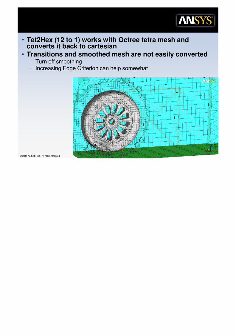
Te%2e$
• Tet2Hex (12 to 1) works with Octree tetra mesh andconverts it back to cartesian
• Transitions and smoothed mesh are not easily converted
– Turn off smoothing– Increasing Edge Criterion can help somewhat

8/10/2019 Icemcfd Tips&Tricks2010
http://slidepdf.com/reader/full/icemcfd-tipstricks2010 37/117
© 2010 ANSYS, Inc. All rights reserved. 37 ANSYS, Inc. Proprietary
*12 I+pro5e+en%
• Orient Octree by LCS
• Tet to Hex by LCS
Oriented Octree Tetra moreeasily converts to orientedANSYS ICEM CFD Hexahybrid mesh

8/10/2019 Icemcfd Tips&Tricks2010
http://slidepdf.com/reader/full/icemcfd-tipstricks2010 38/117
© 2010 ANSYS, Inc. All rights reserved. 38 ANSYS, Inc. Proprietary
Mesh Edi%ing 'i%h "ubse%s
• Subsets are non exclusive groups that youcan use to work with geometry and Mesh
• Experts use Subsets for mesh editing
– Display mesh Quality• Use Histogram to create subsets of the worst elements
• Add layers to subsets to get a better view
• Repair a few of the worst elements and stuck elements
• Run smoother– Check Mesh
• For many of the checks a Subset is the best option
• Add layers to the subset
• Repair issues
• Right click on subsets to add a layer orremove elements or choose modify for moreoptions, such as adding volume elements.

8/10/2019 Icemcfd Tips&Tricks2010
http://slidepdf.com/reader/full/icemcfd-tipstricks2010 39/117
© 2010 ANSYS, Inc. All rights reserved. 39 ANSYS, Inc. Proprietary
e$a FarField
• Hybridize your models– tunnel is usually simple and doesn’t change from run to run
• Use hexa for max efficiency
– Detailed region may be complex in shape• Use Tetra/Prism for max ease of mesh generation
– Merge together
Run Prism thru Both
Convert Tetrato Hexa

8/10/2019 Icemcfd Tips&Tricks2010
http://slidepdf.com/reader/full/icemcfd-tipstricks2010 40/117
© 2010 ANSYS, Inc. All rights reserved. 40 ANSYS, Inc. Proprietary
e$a Far Field
Some Models haveregions of complexityand regions where Hexawould be more
appropriate andrelatively easy to apply

8/10/2019 Icemcfd Tips&Tricks2010
http://slidepdf.com/reader/full/icemcfd-tipstricks2010 41/117
© 2010 ANSYS, Inc. All rights reserved. 41 ANSYS, Inc. Proprietary
&u%%ing i% all %og%her
8/10/2019 Icemcfd Tips&Tricks2010
http://slidepdf.com/reader/full/icemcfd-tipstricks2010 42/117
© 2010 ANSYS, Inc. All rights reserved. 42 ANSYS, Inc. Proprietary
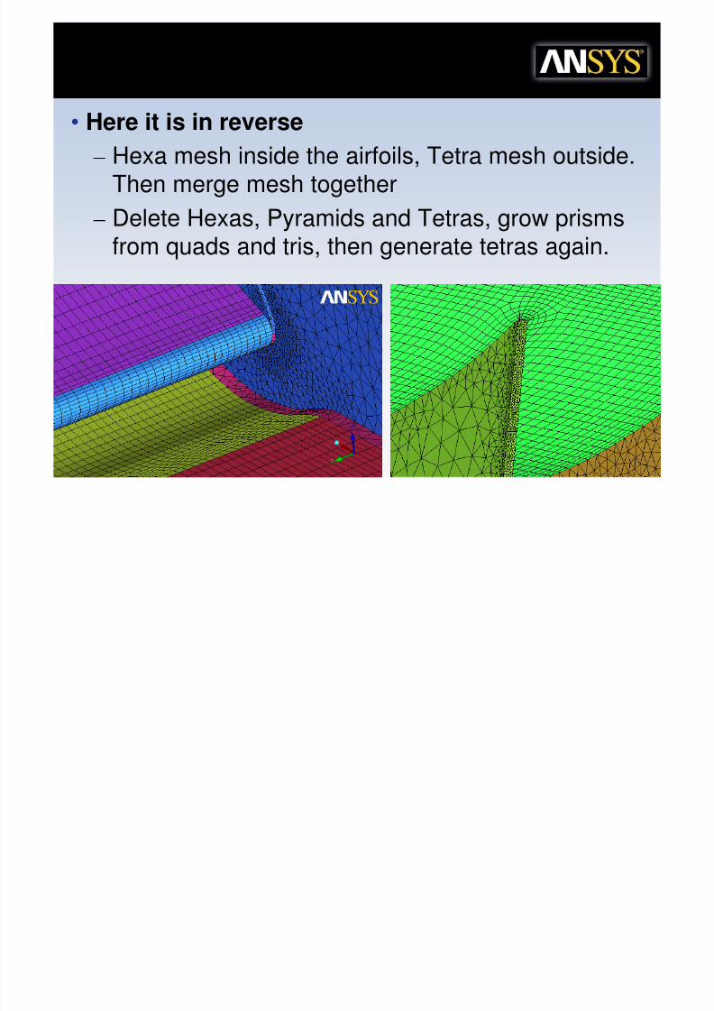
e$a Wings.irfoils
• Here it is in reverse
– Hexa mesh inside the airfoils, Tetra mesh outside.
Then merge mesh together– Delete Hexas, Pyramids and Tetras, grow prisms
from quads and tris, then generate tetras again.
8/10/2019 Icemcfd Tips&Tricks2010
http://slidepdf.com/reader/full/icemcfd-tipstricks2010 43/117
© 2010 ANSYS, Inc. All rights reserved. 43 ANSYS, Inc. Proprietary
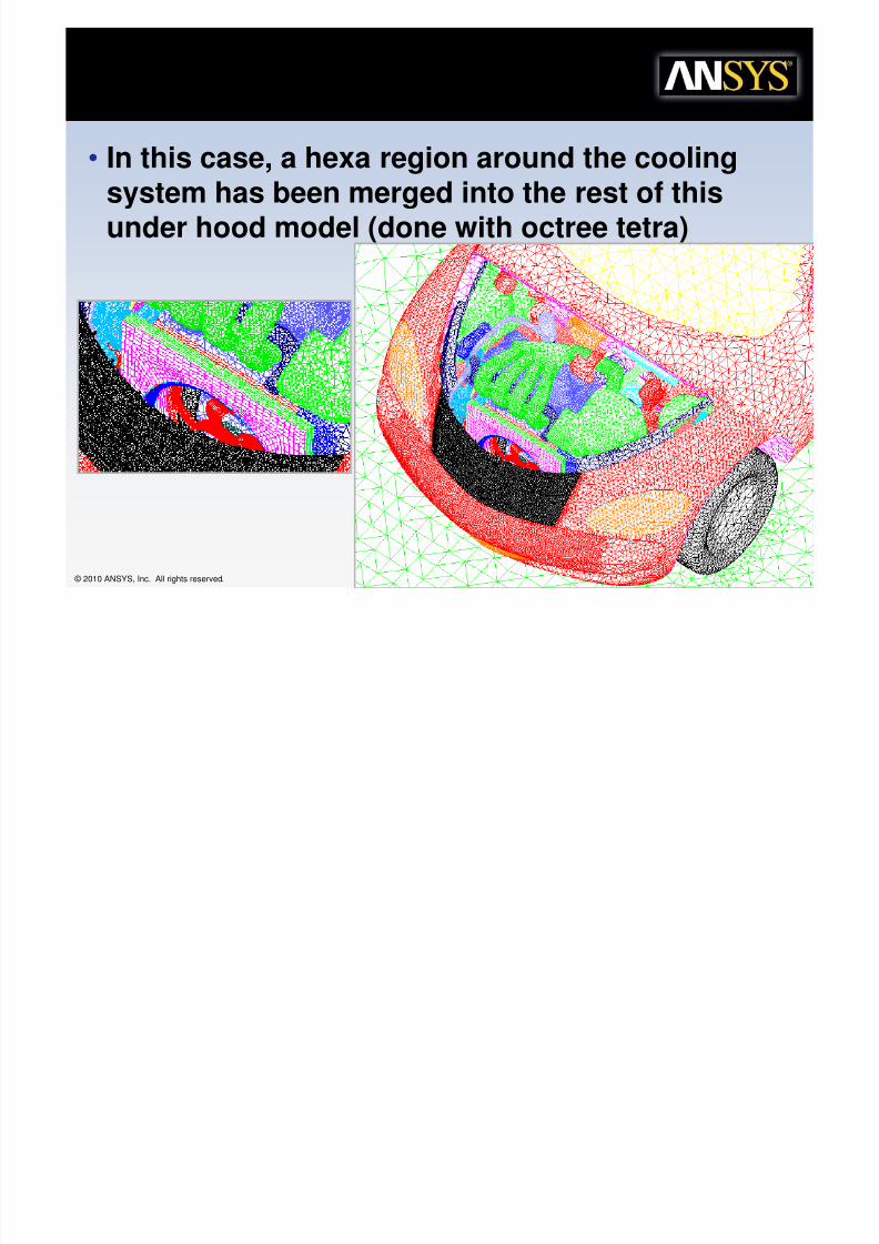
6nderhood
• In this case, a hexa region around the coolingsystem has been merged into the rest of this
under hood model (done with octree tetra)

8/10/2019 Icemcfd Tips&Tricks2010
http://slidepdf.com/reader/full/icemcfd-tipstricks2010 44/117
© 2010 ANSYS, Inc. All rights reserved. 44 ANSYS, Inc. Proprietary
7e, *ules for a successful Merge
• Perimeter must match
– Merged surface parts must share a perimeter 100%
– Both meshes must be projected to this perimeter• Curves in tetra, curves plus edge associations in hexa
• Can not simply merge the bottom of the cylinder with thetop of the box. They do not share a perimeter.
• Must first intersect them to subdivide the top of the box.Then mesh. Then merge the circle on the top of the boxwith the bottom of the cylinder
• Check for green nodes/edges around perimeter
– Size diff between Hexa/tetras will reduce quality.
• Try to stay within 3 to 1 either way; 1 to 1 or
0.7 (hexa) to 1 (tetra) is best.

8/10/2019 Icemcfd Tips&Tricks2010
http://slidepdf.com/reader/full/icemcfd-tipstricks2010 45/117
© 2010 ANSYS, Inc. All rights reserved. 45 ANSYS, Inc. Proprietary
"lide abou% Merging
• More to come

8/10/2019 Icemcfd Tips&Tricks2010
http://slidepdf.com/reader/full/icemcfd-tipstricks2010 46/117
© 2010 ANSYS, Inc. All rights reserved. 46 ANSYS, Inc. Proprietary
e$a Tunnels
• For External Aero,– tunnel is usually simple geometrically and doesn’t change from run to
run
• Use hexa for max efficeincy– Vehicle changes frequently and can be complex in shape
• Use Tetra for max ease of mesh generation
– Merge together
Tetra Vehicle
Hexa Tunnel
T l
8/10/2019 Icemcfd Tips&Tricks2010
http://slidepdf.com/reader/full/icemcfd-tipstricks2010 47/117
© 2010 ANSYS, Inc. All rights reserved. 47 ANSYS, Inc. Proprietary
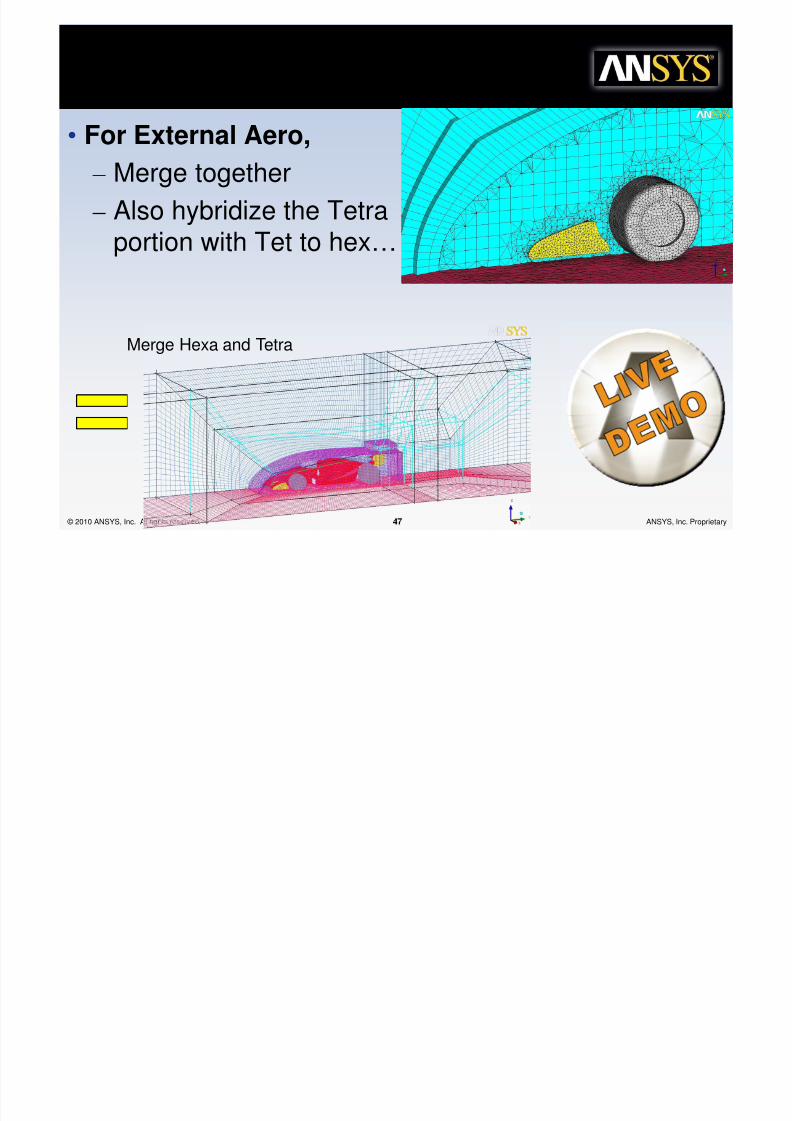
e$a Tunnels
• For External Aero,
– Merge together
– Also hybridize the Tetraportion with Tet to hex…
Merge Hexa and Tetra
Flexible Hybrid Mesh
8/10/2019 Icemcfd Tips&Tricks2010
http://slidepdf.com/reader/full/icemcfd-tipstricks2010 48/117
© 2010 ANSYS, Inc. All rights reserved. 48 ANSYS, Inc. Proprietary
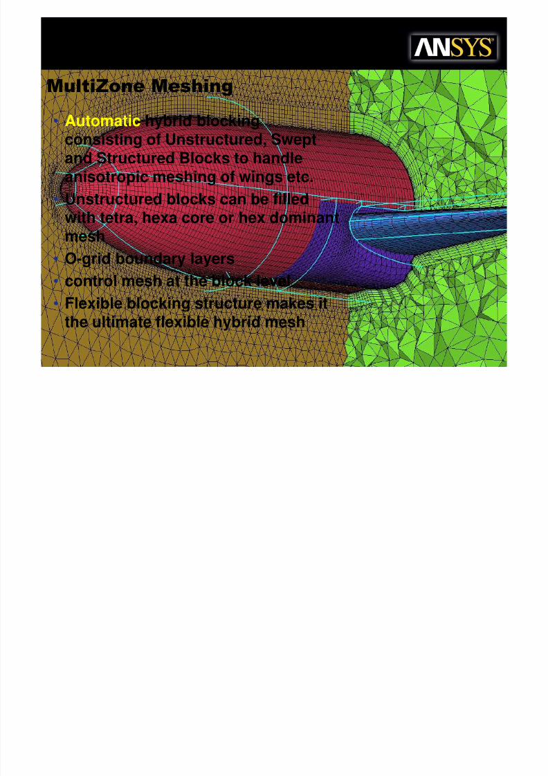
Mul%i8one Meshing
• Automatic hybrid blocking
consisting of Unstructured, Sweptand Structured Blocks to handleanisotropic meshing of wings etc.
• Unstructured blocks can be filledwith tetra, hexa core or hex dominantmesh
• O-grid boundary layers
• control mesh at the block level
• Flexible blocking structure makes itthe ultimate flexible hybrid mesh
Flexible Hybrid Mesh
Flexible Hybrid Mesh

8/10/2019 Icemcfd Tips&Tricks2010
http://slidepdf.com/reader/full/icemcfd-tipstricks2010 49/117
© 2010 ANSYS, Inc. All rights reserved. 49 ANSYS, Inc. Proprietary
Mul%i8one Meshing
Flexible Hybrid Mesh
M l%i8 &

8/10/2019 Icemcfd Tips&Tricks2010
http://slidepdf.com/reader/full/icemcfd-tipstricks2010 50/117
© 2010 ANSYS, Inc. All rights reserved. 50 ANSYS, Inc. Proprietary
Mul%i8one &rocess
Geometry Import & Repair Mesh Params
Bottom Up(automatic patch
based)
Top Down (Manual
patch Independent)
Interactively modifysurface blocking and
adjust edge params
2D to 3D Fill wBoundary layersMore
interactive
adjustment
Generate Mesh
Check Mesh
Output to
Solver
AdjustGeometry
8/10/2019 Icemcfd Tips&Tricks2010
http://slidepdf.com/reader/full/icemcfd-tipstricks2010 51/117
© 2010 ANSYS, Inc. All rights reserved. 51 ANSYS, Inc. Proprietary
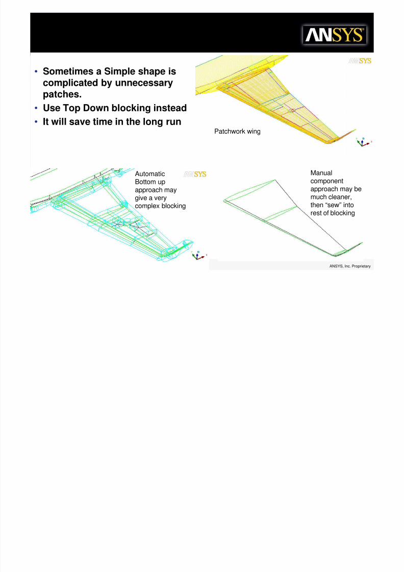
• Sometimes a Simple shape iscomplicated by unnecessarypatches.
• Use Top Down blocking instead
• It will save time in the long runPatchwork wing
AutomaticBottom upapproach maygive a very
complex blocking
Manualcomponentapproach may bemuch cleaner,
then “sew” intorest of blocking
Mul%i8one "'eep De+o

8/10/2019 Icemcfd Tips&Tricks2010
http://slidepdf.com/reader/full/icemcfd-tipstricks2010 52/117
© 2010 ANSYS, Inc. All rights reserved. 52 ANSYS, Inc. Proprietary
Mul%i8one "'eep De+o
• Sweep with multiple sources and targets…
Mul%i8one De+o
8/10/2019 Icemcfd Tips&Tricks2010
http://slidepdf.com/reader/full/icemcfd-tipstricks2010 53/117
© 2010 ANSYS, Inc. All rights reserved. 53 ANSYS, Inc. Proprietary
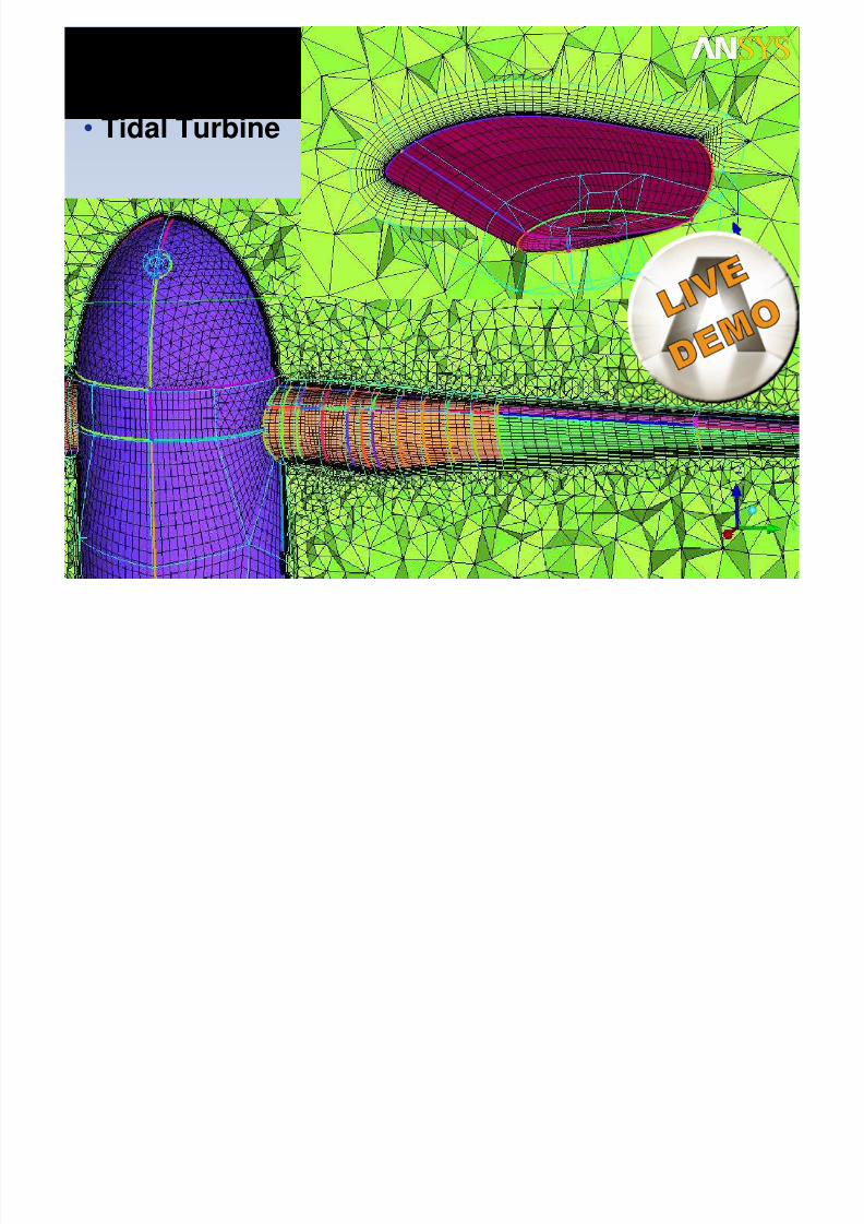
Mul%i8one De+o
• Tidal Turbine
&ris+ &repara%ion

8/10/2019 Icemcfd Tips&Tricks2010
http://slidepdf.com/reader/full/icemcfd-tipstricks2010 54/117
© 2010 ANSYS, Inc. All rights reserved. 54 ANSYS, Inc. Proprietary
&ris+ &repara%ion
– Start with good tetra or tri-surface mesh
• It may be difficult to smooth prism after it is generated, it is relatively easy to improve thesurface mesh before hand
– Check aspect ratios / quality
– Check and fix all diagnostics• Single/multiple edges, Non-manifold vertices, Duplicate elements
• Laplace smooth• often better without tetra, then fill w/ Delaunay after smooth
• Delaunay mesh will have fewer nodes and smoother transitions; easierfor prism – Visually scan the surface mesh
– Look for kinks or sharp tent-like structures in the mesh
– Diagnostics may not reveal all surface discrepancies
– Make sure part associations are correct– Look for a few elements in one part scattered among another part
– Extruding from a few isolated elements and none of their neighbors will likely crash
– Modify part assignments of offending elements
Mesh "+oo%hing

8/10/2019 Icemcfd Tips&Tricks2010
http://slidepdf.com/reader/full/icemcfd-tipstricks2010 55/117
© 2010 ANSYS, Inc. All rights reserved. 55 ANSYS, Inc. Proprietary
g
• Use the Laplacian Smoother
• Moves the point towards an “ideal” location defined asthe average of the surrounding nodes
– Has the effect of averaging the surface mesh transitions andtriangles become more equilateral
• Better for bottom up fill and prism
•Laplacian smootherrp= Avg (ri)
p
1
2i
&ris+ "e%%ings

8/10/2019 Icemcfd Tips&Tricks2010
http://slidepdf.com/reader/full/icemcfd-tipstricks2010 56/117
© 2010 ANSYS, Inc. All rights reserved. 56 ANSYS, Inc. Proprietary
&ris+ "e%%ings
• Leave initial height as “0”
– This causes the initial height to float in order toreduce the volume change between the last prismand adjacent tetra.
&,ra+ids due %o in%ersec%ion

8/10/2019 Icemcfd Tips&Tricks2010
http://slidepdf.com/reader/full/icemcfd-tipstricks2010 57/117
© 2010 ANSYS, Inc. All rights reserved. 57 ANSYS, Inc. Proprietary
&,ra+ids due %o in%ersec%ion
• If the height is floating, you canrefine the mesh to control the prismheight and prevent intersection
from being resolved with pyramids
•Before refinement, prism
layers intersected andpyramids were used
•after refinement there is lotsof clearance (no pyramids)
Auto reduction (discussedlater) can also prevent
collision without pyramids
&ris+ "e%%ings
8/10/2019 Icemcfd Tips&Tricks2010
http://slidepdf.com/reader/full/icemcfd-tipstricks2010 58/117
© 2010 ANSYS, Inc. All rights reserved. 58 ANSYS, Inc. Proprietary
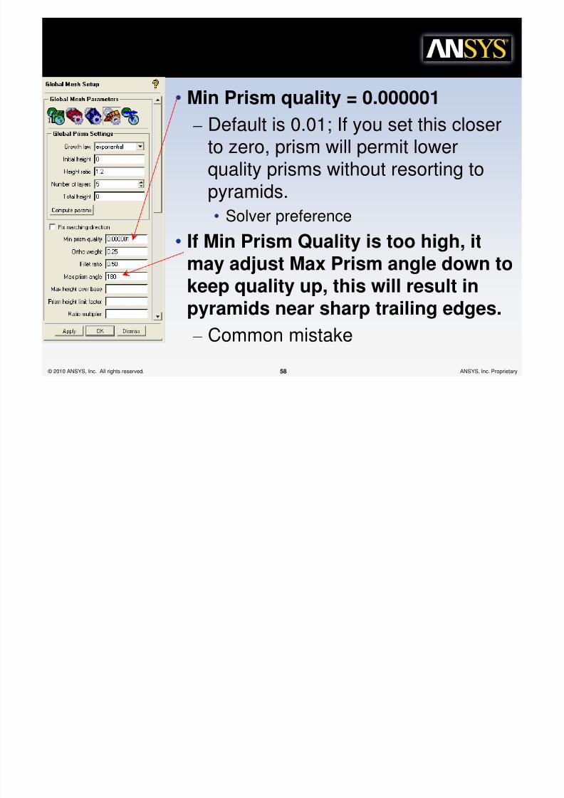
&ris+ "e%%ings
• Min Prism quality = 0.000001
– Default is 0.01; If you set this closer
to zero, prism will permit lowerquality prisms without resorting to
pyramids.
• Solver preference• If Min Prism Quality is too high, it
may adjust Max Prism angle down to
keep quality up, this will result inpyramids near sharp trailing edges.
– Common mistake
&ris+ "e%%ings
8/10/2019 Icemcfd Tips&Tricks2010
http://slidepdf.com/reader/full/icemcfd-tipstricks2010 59/117
© 2010 ANSYS, Inc. All rights reserved. 59 ANSYS, Inc. Proprietary
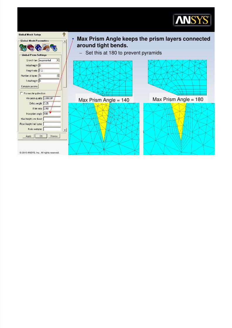
Max Prism Angle = 140 Max Prism Angle = 180
&ris+ "e%%ings
• Max Prism Angle keeps the prism layers connectedaround tight bends.
– Set this at 180 to prevent pyramids
&ris+ "e%%ings

8/10/2019 Icemcfd Tips&Tricks2010
http://slidepdf.com/reader/full/icemcfd-tipstricks2010 60/117
© 2010 ANSYS, Inc. All rights reserved. 60 ANSYS, Inc. Proprietary
s "e%% gs
• Advanced prism params, Auto Reduction
– Proximity can cause prism to stop and give pyramidsinstead.
– This option causes the prisms to squeeze down– This is fixed with redistribute prisms
Pyramids
Reduced (Squished) prismsRedistributed andNo Pyramids
*edis%ribu%e &ris+
8/10/2019 Icemcfd Tips&Tricks2010
http://slidepdf.com/reader/full/icemcfd-tipstricks2010 61/117
© 2010 ANSYS, Inc. All rights reserved. 61 ANSYS, Inc. Proprietary
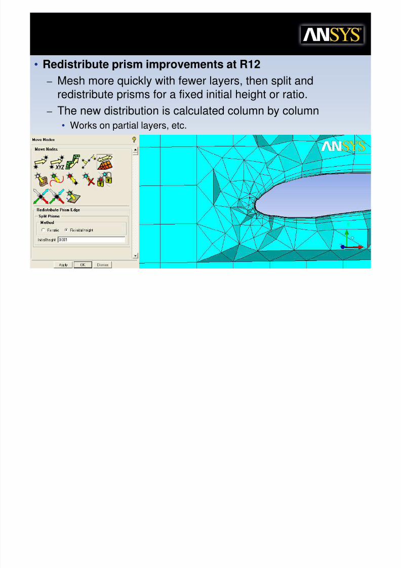
• Redistribute prism improvements at R12
– Mesh more quickly with fewer layers, then split andredistribute prisms for a fixed initial height or ratio.
– The new distribution is calculated column by column
• Works on partial layers, etc.
"+oo%h &ris+

8/10/2019 Icemcfd Tips&Tricks2010
http://slidepdf.com/reader/full/icemcfd-tipstricks2010 62/117
© 2010 ANSYS, Inc. All rights reserved. 62 ANSYS, Inc. Proprietary
• Prism is difficult to smooth which is why we try tostart with as good a surface mesh as possible.
• Once the mesh is done, we recommend smoothing
without the prisms (Penta_6). Set them to frozen.This will only improve the tetra mesh. Do this untilyou don’t see any further improvements.
– Turning on the allow refinement option may help also, butuse judiciously or you may add many new elements.
• If you want to smooth some more turn on thesmooth for the Penta_6 elements, set the “up toValue” very low (< 0.05) so that most of the prismmesh is left alone.
– I also recommend saving before smoothing prisms incase you don’t like the result.
• In ICEM CFD prism quality is judged more harshlythan TGrid and other meshers.
– 0.01 or even 0.0001 is ok depending on your solver
Infla%ion fro+ 9uads
8/10/2019 Icemcfd Tips&Tricks2010
http://slidepdf.com/reader/full/icemcfd-tipstricks2010 63/117
© 2010 ANSYS, Inc. All rights reserved. 63 ANSYS, Inc. Proprietary
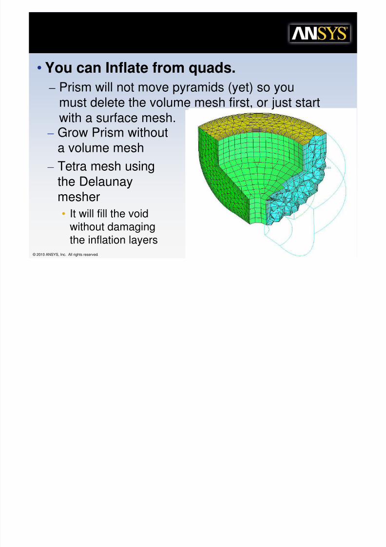
• You can Inflate from quads.
– Prism will not move pyramids (yet) so you
must delete the volume mesh first, or just startwith a surface mesh.
– Grow Prism without
a volume mesh– Tetra mesh using
the Delaunay
mesher• It will fill the void
without damaging
the inflation layers
6se E$is%ing 9uad :a,ers

8/10/2019 Icemcfd Tips&Tricks2010
http://slidepdf.com/reader/full/icemcfd-tipstricks2010 64/117
© 2010 ANSYS, Inc. All rights reserved. 64 ANSYS, Inc. Proprietary
• You can grow Prism along quads.
– Need to turn on Prism advanced
option for “Use Existing QuadLayers”
– Tricky to set up…
6se E$is%ing 9uad :a,ers

8/10/2019 Icemcfd Tips&Tricks2010
http://slidepdf.com/reader/full/icemcfd-tipstricks2010 65/117
© 2010 ANSYS, Inc. All rights reserved. 65 ANSYS, Inc. Proprietary
• Generate Hexa portion and tetra portion, Merge
– This is to connect the surface tris with the quads
• Delete all the hexas, keep only the envelope around the
tetra region, also delete the tetras– It will not align if there are Hexas behind the quads
– It will not inflate along Pyramids
– Be careful not to smooth QUAD faces so we can merge with Hexasagain later
– We hope to remove these tricky requirements at R13
• Setup prism params to ~match quad layers.
• Run Prism without volume mesh• Fill remaining volume with Delaunay tetra
• Load previous Hexa portion and Merge nodes with a
small tolerance.
"e%%ing &ris+ &ara+e%ers on
Cur5es

8/10/2019 Icemcfd Tips&Tricks2010
http://slidepdf.com/reader/full/icemcfd-tipstricks2010 66/117
© 2010 ANSYS, Inc. All rights reserved. 66 ANSYS, Inc. Proprietary
• Mesh > Curve Mesh Setup
• You can get Prism to transition linearly acrossa surface by not setting a height on thesurface, but instead set a different height on
each curve on the opposite sides of the prismsurface
• Height ratio and Num. of layers have no affecton prism for curve settings
Cur5es
Height = 0.003
Height =0.01
Height = 0 onsurface
&ris+ Transi%ion

8/10/2019 Icemcfd Tips&Tricks2010
http://slidepdf.com/reader/full/icemcfd-tipstricks2010 67/117
© 2010 ANSYS, Inc. All rights reserved. 67 ANSYS, Inc. Proprietary
• You can get Prism to transition linearly by notsetting a height on the wall, but instead set a
different height on each curve on theopposite edges of the prism surface…
Height =
0.01 Height = 0.003Height = 0 onsurface
igh spec% *a%io +esh
8/10/2019 Icemcfd Tips&Tricks2010
http://slidepdf.com/reader/full/icemcfd-tipstricks2010 68/117
© 2010 ANSYS, Inc. All rights reserved. 68 ANSYS, Inc. Proprietary
• Several ways
– Stretch and squish works if the high aspect ratio isin one direction only• Squish geometry, mesh with uniform mesh and then
stretch (scale in one direction) the mesh to get highaspect ratio.
– Surface mesh with high aspect ratio quads, growprisms and bottom up tetra… Good for someexternal aero applications
– MultiZone, use hexa edge params to adjust meshaspect ratio. Works on certain cases if thegeometry is good quality.
";uish and "%re%ch
8/10/2019 Icemcfd Tips&Tricks2010
http://slidepdf.com/reader/full/icemcfd-tipstricks2010 69/117
© 2010 ANSYS, Inc. All rights reserved. 69 ANSYS, Inc. Proprietary
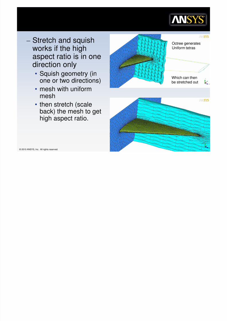
– Stretch and squishworks if the highaspect ratio is in onedirection only• Squish geometry (in
one or two directions)
• mesh with uniformmesh
• then stretch (scaleback) the mesh to get
high aspect ratio.
Octree generatesUniform tetras
Which can thenbe stretched out
igh spec% ra%io Tri<s
8/10/2019 Icemcfd Tips&Tricks2010
http://slidepdf.com/reader/full/icemcfd-tipstricks2010 70/117
© 2010 ANSYS, Inc. All rights reserved. 70 ANSYS, Inc. Proprietary
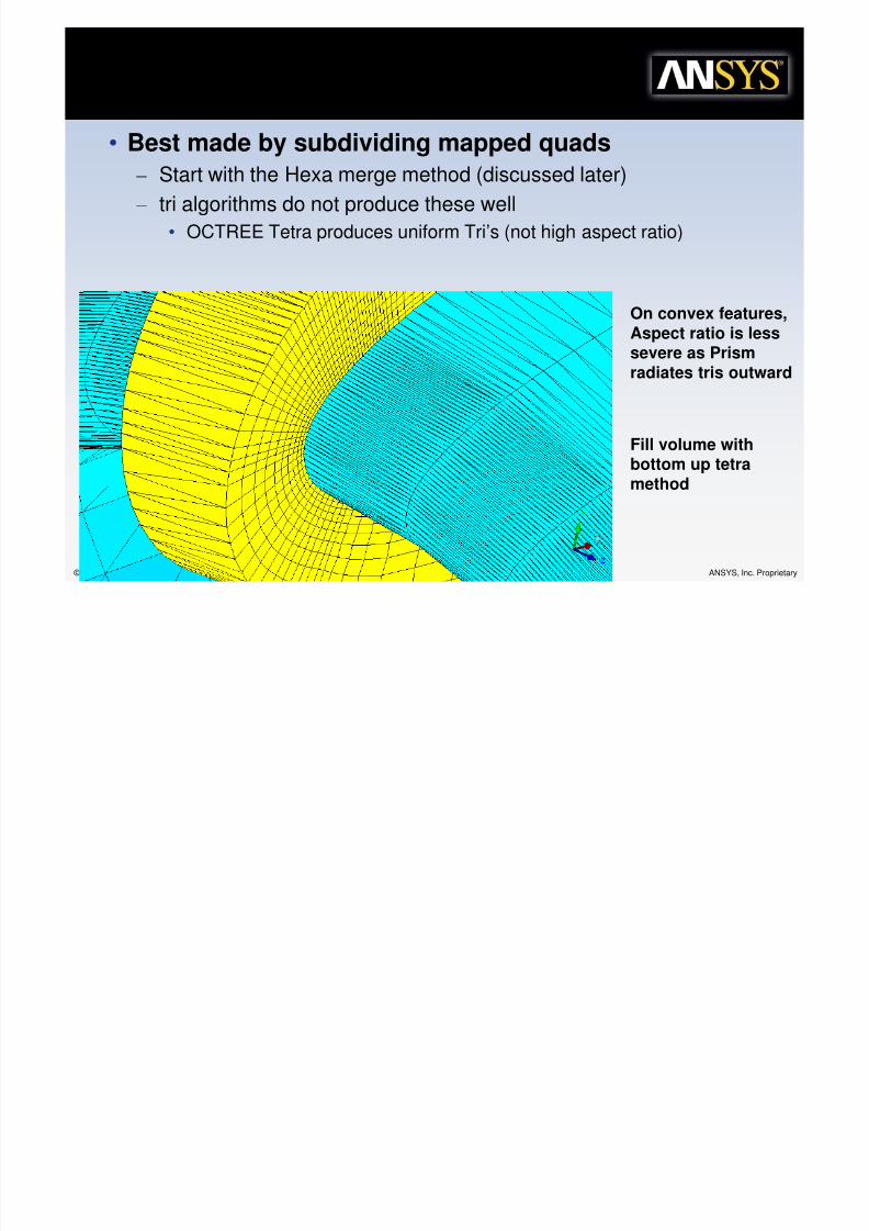
• Best made by subdividing mapped quads
– Start with the Hexa merge method (discussed later)
– tri algorithms do not produce these well
• OCTREE Tetra produces uniform Tri’s (not high aspect ratio)
On convex features,
Aspect ratio is lesssevere as Prismradiates tris outward
Fill volume withbottom up tetramethod
=olu+e Change

8/10/2019 Icemcfd Tips&Tricks2010
http://slidepdf.com/reader/full/icemcfd-tipstricks2010 71/117
© 2010 ANSYS, Inc. All rights reserved. 71 ANSYS, Inc. Proprietary
• With bottom up tetra methods, highaspect ratio tri’s, quads or prismsresult in adjacent high aspect ratio
tetras or pyramids.• However the Elements between and
adjacent to those high aspect ratio
elements may have a lower aspectratio and therefore much morevolume.
• TGrid Pyramids may be better…
– (hope to improve for R12)
&ris+
8/10/2019 Icemcfd Tips&Tricks2010
http://slidepdf.com/reader/full/icemcfd-tipstricks2010 72/117
© 2010 ANSYS, Inc. All rights reserved. 72 ANSYS, Inc. Proprietary
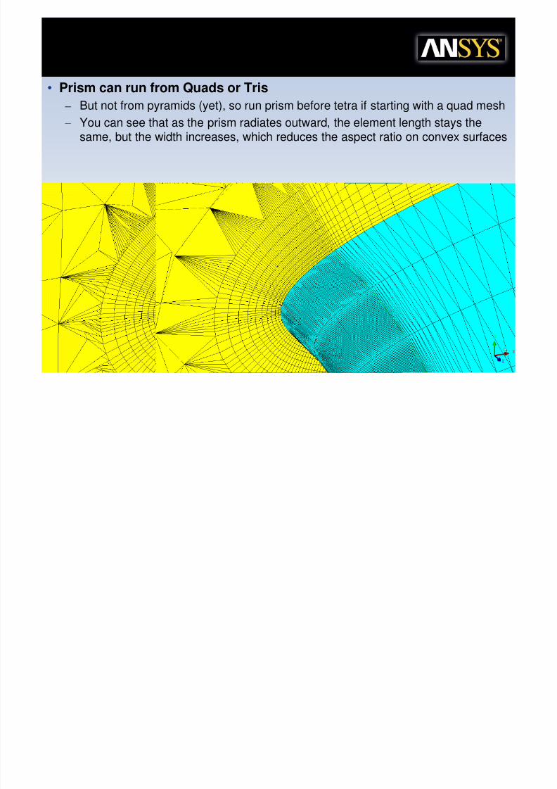
• Prism can run from Quads or Tris
– But not from pyramids (yet), so run prism before tetra if starting with a quad mesh
– You can see that as the prism radiates outward, the element length stays thesame, but the width increases, which reduces the aspect ratio on convex surfaces
Mul%i8one
8/10/2019 Icemcfd Tips&Tricks2010
http://slidepdf.com/reader/full/icemcfd-tipstricks2010 73/117
© 2010 ANSYS, Inc. All rights reserved. 73 ANSYS, Inc. Proprietary
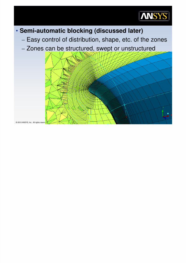
• Semi-automatic blocking (discussed later)
– Easy control of distribution, shape, etc. of the zones
– Zones can be structured, swept or unstructured
Mul%i8one

8/10/2019 Icemcfd Tips&Tricks2010
http://slidepdf.com/reader/full/icemcfd-tipstricks2010 74/117
© 2010 ANSYS, Inc. All rights reserved. 74 ANSYS, Inc. Proprietary
• Change the shape of mesh by simply contouringthe “ZONE” edges.
"+oo%hing

8/10/2019 Icemcfd Tips&Tricks2010
http://slidepdf.com/reader/full/icemcfd-tipstricks2010 75/117
© 2010 ANSYS, Inc. All rights reserved. 75 ANSYS, Inc. Proprietary
• Smoothing can adjust the angle or volume ratio ofelements
e$a /locking in si+ple s%eps…
8/10/2019 Icemcfd Tips&Tricks2010
http://slidepdf.com/reader/full/icemcfd-tipstricks2010 76/117
© 2010 ANSYS, Inc. All rights reserved. 76 ANSYS, Inc. Proprietary
• Once you decide on the blocking topology you want (the hardest part),generating the Hexa blocking is just a series of the same steps
– Split blocks (could be an Ogrid split) to get the topology you want.
– Delete blocks that are not part of your topology
– Associate the blocks with the geometry
– Move the vertices into place so they fit to the geometry and blocks are goodquality
– Adjust edge params for quality and transition
• There is a lot of iteration, but generally, it pays to go as far as you can witheach split before things go to complicated…
– Delete unneded blocks as soon as you can to reduce complexity
– Associated the blocking as soon as an edge can be matched with a curve (or
chain of curves) so you will have less work to do after you make further splits.– Move the verts into place while you only have a few splits so future splits will
already be aligned.
– Get as much done before you add a boundary OGrid so you won’t have tomove OGrid verts later.
Grids

8/10/2019 Icemcfd Tips&Tricks2010
http://slidepdf.com/reader/full/icemcfd-tipstricks2010 77/117
© 2010 ANSYS, Inc. All rights reserved. 77 ANSYS, Inc. Proprietary
• 2 main uses for OGRID…
– Capture Topology:
• OGrid can be used to get the basic blocking shape laid out. Is
your basic topology an OGrid or a Cgrid? Do you havefeatures within your model (such as drilled holes) that wouldbest be captured with an Ogrid?
• Use these as early in the blocking process as possible
– Boundary layer:
• OGrid used to aling mesh with the walls. Solves problem ofHexas mapped to a curve and helps align the besh forboundary layer analysis.
• Best if used late in the blocking process after all other stepsare complete.
>Grid Defini%ion

8/10/2019 Icemcfd Tips&Tricks2010
http://slidepdf.com/reader/full/icemcfd-tipstricks2010 78/117
© 2010 ANSYS, Inc. All rights reserved. 78 ANSYS, Inc. Proprietary
• An O-grid is a series of blocks created in one step which arranges grid linesinto an “O” shape or a wrapping nature
• 3 basic types created through the same operation all referred to as “O-grids”
• O-grid
• C-grid (half O-grid)
• L-grid (quarter O-grid)
• Reduce skew where a block corner must lie on a continuous curve/surface
• Cylinders
• Complex geometries
• Improves efficiency of node clustering near walls for CFD applications
O-grid C-grid L-grid
No O-grid(H-grid)
O-grid
Crea%ing an >Grid

8/10/2019 Icemcfd Tips&Tricks2010
http://slidepdf.com/reader/full/icemcfd-tipstricks2010 79/117
© 2010 ANSYS, Inc. All rights reserved. 79 ANSYS, Inc. Proprietary
• Select blocks for O-grid – Can select by visible, part, around face, around
edge, around vertex, 2 corner method, or individualselection
Note: Internal block has all internal (blue) edges and vertices
7 blocks in 3D
5 blocks in 2D
Select specific blocksor around face, edge,or vertex
>Grid>dding Faces
8/10/2019 Icemcfd Tips&Tricks2010
http://slidepdf.com/reader/full/icemcfd-tipstricks2010 80/117
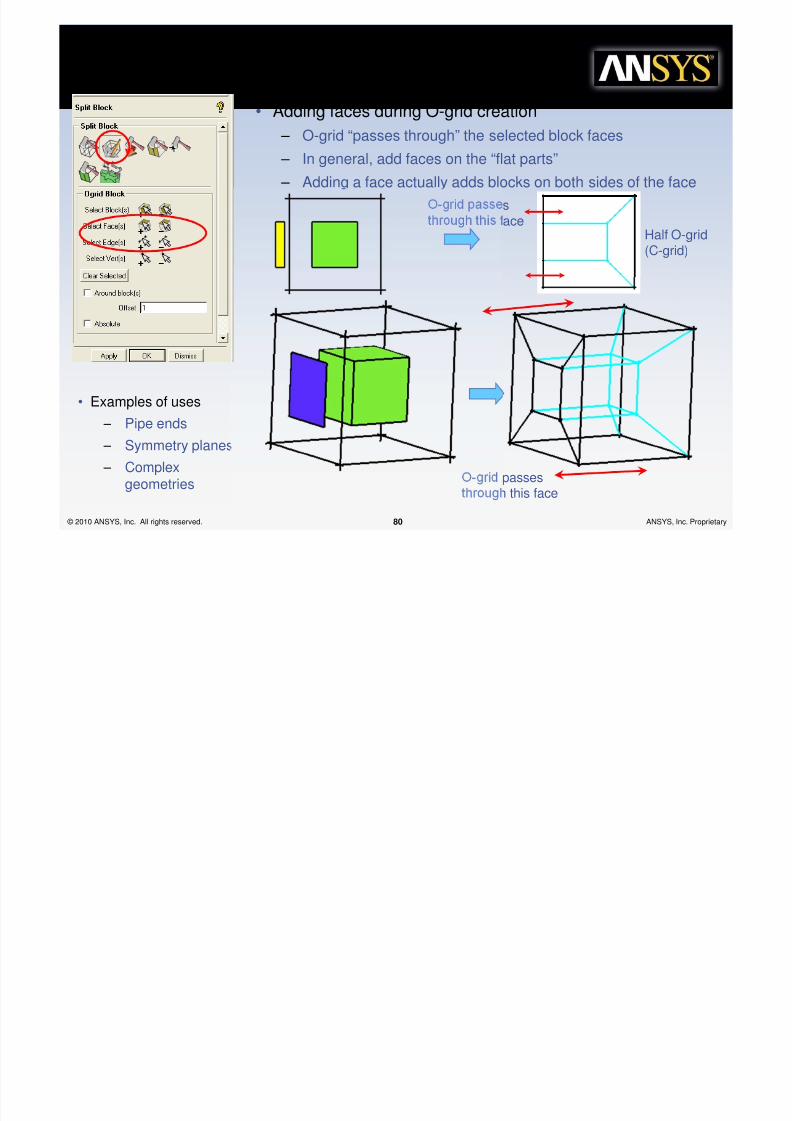
© 2010 ANSYS, Inc. All rights reserved. 80 ANSYS, Inc. Proprietary
O-grid passesthrough this face
• Adding faces during O-grid creation – O-grid “passes through” the selected block faces
– In general, add faces on the “flat parts”
– Adding a face actually adds blocks on both sides of the face
• Examples of uses – Pipe ends
– Symmetry planes
– Complexgeometries
O-grid passesthrough this face
Half O-grid(C-grid)
dding Mul%iple Faces

8/10/2019 Icemcfd Tips&Tricks2010
http://slidepdf.com/reader/full/icemcfd-tipstricks2010 81/117
© 2010 ANSYS, Inc. All rights reserved. 81 ANSYS, Inc. Proprietary
• Any number of faces can be added around a selected block – If all the faces are added around a block, the result is no change
since the O-grid passes through all the faces
Quarter O-grid(L-grid)
Seen as a C-grid in onedirection andan L-grid inanotherdirection
Quarter O-grids
can be used toblock triangularshapes
>Grid>round /locks

8/10/2019 Icemcfd Tips&Tricks2010
http://slidepdf.com/reader/full/icemcfd-tipstricks2010 82/117
© 2010 ANSYS, Inc. All rights reserved. 82 ANSYS, Inc. Proprietary
• Select Around block(s) to create the O-grid around theselected blocks
– Useful for creating wrap-around grid around a solid object
– Examples
• Opposite order of creation from block around/O-grid inside
• Flow over a cylinder
• Boundary layer resolution around an airplane or car body
"caling an >Grid

8/10/2019 Icemcfd Tips&Tricks2010
http://slidepdf.com/reader/full/icemcfd-tipstricks2010 83/117
© 2010 ANSYS, Inc. All rights reserved. 83 ANSYS, Inc. Proprietary
• O-grids can be re-sized after or during creation – By default the O-grid size is set to minimize block
distortion
– You are actually scaling all parallel O-grid (radial) edgesto the selected edge
– The selected edge is given a factor of 1 – Numbers < 1 will shrink the edge and thus create a
larger inner block
Selected edge
factor = 1
Factor = 0.3
Wh, >Grid?
8/10/2019 Icemcfd Tips&Tricks2010
http://slidepdf.com/reader/full/icemcfd-tipstricks2010 84/117
© 2010 ANSYS, Inc. All rights reserved. 84 ANSYS, Inc. Proprietary
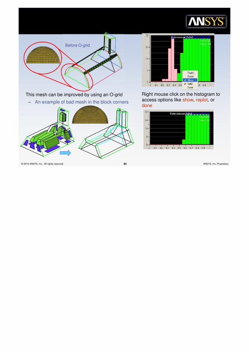
This mesh can be improved by using an O-grid
– An example of bad mesh in the block corners
Before O-grid
Right mouse click on the histogram to
access options like show, replot, ordone
Mul%iple Wa,s of /locking %he
"a+e Geo+e%r,

8/10/2019 Icemcfd Tips&Tricks2010
http://slidepdf.com/reader/full/icemcfd-tipstricks2010 85/117
© 2010 ANSYS, Inc. All rights reserved. 85 ANSYS, Inc. Proprietary
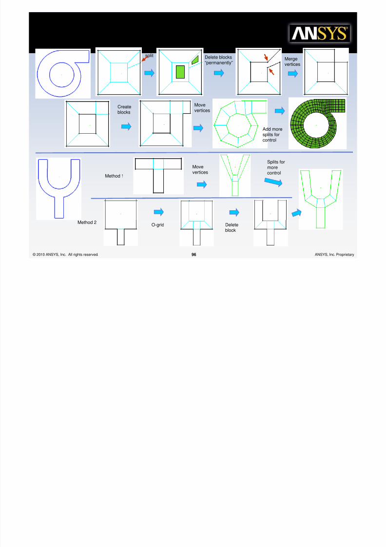
• Creating a fork by Merge vertices
#1 #2
#3 #4 #5
Mergevertices
Splits
Deleteblock
OrCollapse
Block
Mul%iple Wa,s of /locking %he "a+e
Geo+e%r,

8/10/2019 Icemcfd Tips&Tricks2010
http://slidepdf.com/reader/full/icemcfd-tipstricks2010 86/117
© 2010 ANSYS, Inc. All rights reserved. 86 ANSYS, Inc. Proprietary
• Creating a fork by Extrude faces
Extrude 1
Extrude 2
Associate
#1 #2 #3
#4 #5
Mul%iple Wa,s of /locking %he "a+e
Geo+e%r,
C i f k i h T d h d

8/10/2019 Icemcfd Tips&Tricks2010
http://slidepdf.com/reader/full/icemcfd-tipstricks2010 87/117
© 2010 ANSYS, Inc. All rights reserved. 87 ANSYS, Inc. Proprietary
split
• Creating a fork with Top-down methods
Two
quarterO-grids
OnequarterO-grid
OnequarterO-grid
Deleteblocks
Move
vertices
Topolog,

8/10/2019 Icemcfd Tips&Tricks2010
http://slidepdf.com/reader/full/icemcfd-tipstricks2010 88/117
© 2010 ANSYS, Inc. All rights reserved. 88 ANSYS, Inc. Proprietary
•What is common inthese?
– Their block topology
Topolog,
All these parts ha e the same
Thi h li l bl ki

8/10/2019 Icemcfd Tips&Tricks2010
http://slidepdf.com/reader/full/icemcfd-tipstricks2010 89/117
© 2010 ANSYS, Inc. All rights reserved. 89 ANSYS, Inc. Proprietary
• All these parts have the samebasic topology
– Blocking strategy for all pipes aresimilar.
– Single block with o-grid
– The only difference is the number ofsplits added to help control theblocking
– Create the one block, then split, andadd O-grid last
Single blockwith o-grid
Single block with 5splits and o-grid
splitsSingle block withmultiple splits and o-grid
This helical blockingis quickly createdwith extrude alongcurve
/asic /lock "%ruc%ures

8/10/2019 Icemcfd Tips&Tricks2010
http://slidepdf.com/reader/full/icemcfd-tipstricks2010 90/117
© 2010 ANSYS, Inc. All rights reserved. 90 ANSYS, Inc. Proprietary
Meshinsidefillet
O-grid isrequired unlessapproximatinga corner usinglarge mesh size
Badquality O-grid necessary
Acceptablequality
Badquality
O-grid necessary
Badquality O-gridnecessary
O-grid
Quality is
However, an
O-grid makes
/asic /lock "%ruc%ures

8/10/2019 Icemcfd Tips&Tricks2010
http://slidepdf.com/reader/full/icemcfd-tipstricks2010 91/117
© 2010 ANSYS, Inc. All rights reserved. 91 ANSYS, Inc. Proprietary
Meshoutsidefillet
Quality isgood withoutan O-grid
O grid makesnormal gridlines forboundarylayerresolution
Meshinside andoutsidefillet.Combinepreviousexamples
This method needs large mesh size
Vertex atend of fillet
This is notpreferablebecausequality islower
There should beone vertex at thecenter of everyapproximate 90degree bend
Mesh onlyin ring
Mesh inboth
Split anyradialedge
Deletecenterblock
/asic /lock "%ruc%ures
8/10/2019 Icemcfd Tips&Tricks2010
http://slidepdf.com/reader/full/icemcfd-tipstricks2010 92/117
© 2010 ANSYS, Inc. All rights reserved. 92 ANSYS, Inc. Proprietary
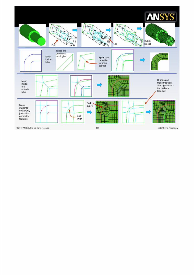
Split Split
Deleteblocks
Meshinsidetube
Tubes are
one-blocktopologies
Splits canbe addedfor morecontrol
Meshinsideandoutsidetube
Manystudentsmistakenly just split atgeometryfeatures
Badquality
O-grids canmake this workalthough it is notthe preferredtopology
Badangle
/asic /lock "%ruc%ures
We must use thestraight-through split
Bad
angle

8/10/2019 Icemcfd Tips&Tricks2010
http://slidepdf.com/reader/full/icemcfd-tipstricks2010 93/117
© 2010 ANSYS, Inc. All rights reserved. 93 ANSYS, Inc. Proprietary
g g pstrategy as in theprevious example forgrid lines to flow withthe inner tube
Deleteblock
g
Add O-grid formeshing insidecurvature
BlocksselectedforcreatingO-grid
2 splits
Split forbetterblockingcontrol
There are multiple methodsof producing the Y-blockstructure
Method 1Quarter O-grid
Movevertices
These may also be called wedge blocks.They can be used to effectively terminate meshfrom continuing through the geometry
/asic /lock "%ruc%ures
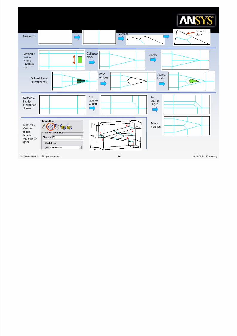
Method 2
splitMovevertices
Create
block
8/10/2019 Icemcfd Tips&Tricks2010
http://slidepdf.com/reader/full/icemcfd-tipstricks2010 94/117
© 2010 ANSYS, Inc. All rights reserved. 94 ANSYS, Inc. Proprietary
Method 3InsideH-grid
( bottom-up)
Delete blocks“permanently”
2 splits
Movevertices
Createblock
Collapseblock
Method 4InsideH-grid (top-down)
1stquarterO-grid
2ndquarterO-grid
Movevertices
Method 5Createblockfunction(quarter O-grid)
1
2
3
4
5
6
/asic /lock "%ruc%ures
Add
quarterO-grid
Move
vertices

8/10/2019 Icemcfd Tips&Tricks2010
http://slidepdf.com/reader/full/icemcfd-tipstricks2010 95/117
© 2010 ANSYS, Inc. All rights reserved. 95 ANSYS, Inc. Proprietary
Add O-gridfor round
Since the round iscloser to 180degrees than 90degrees, having twoblock corners maybe better
Add O-grid
for round
A Y-blockstructurecan also beused for acircle
Useful for fillingthe center ofgeometry that isperiodic inmultiples of 3
Add O-grid Movevertices
g
/asic /lock "%ruc%ures
splitDelete blocks“permanently” Merge
vertices
8/10/2019 Icemcfd Tips&Tricks2010
http://slidepdf.com/reader/full/icemcfd-tipstricks2010 96/117
© 2010 ANSYS, Inc. All rights reserved. 96 ANSYS, Inc. Proprietary
Movevertices
p y vertices
Createblocks
Add moresplits forcontrol
Method 2
Method 1
O-grid
Movevertices
Deleteblock
Splits formorecontrol
/asic /lock "%ruc%ures
Thinthicknesses
First
block theoutside
Then put an
O-grid insideall blocks

8/10/2019 Icemcfd Tips&Tricks2010
http://slidepdf.com/reader/full/icemcfd-tipstricks2010 97/117
© 2010 ANSYS, Inc. All rights reserved. 97 ANSYS, Inc. Proprietary
are easily donewith an O-grid
(addappropriatefaces)
Deletethe insideblocks
ScanplaneResulting blocks
Method 1
Method 2
Vertex moved slightly offintersection for better angles
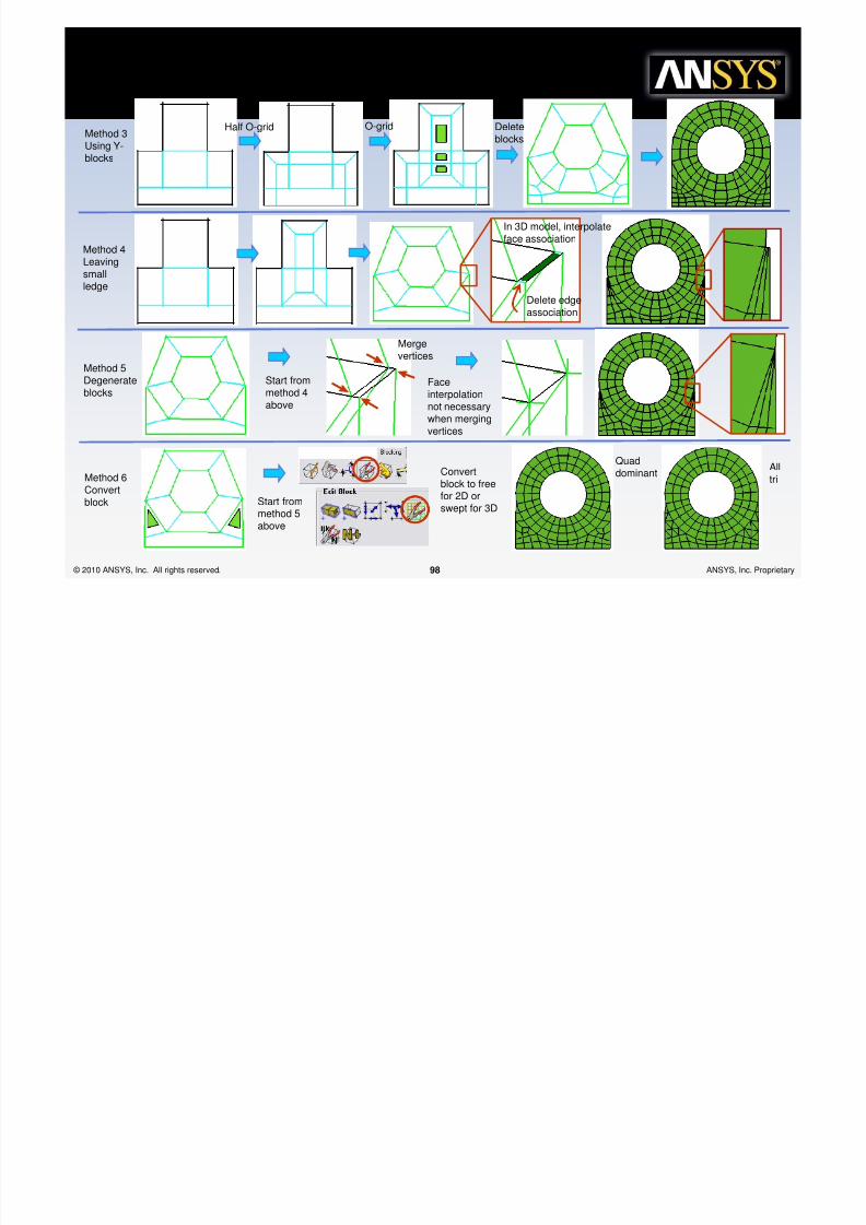
/asic /lock "%ruc%ures
Method 3Using Y-
Half O-gridO-grid
Deleteblocks
8/10/2019 Icemcfd Tips&Tricks2010
http://slidepdf.com/reader/full/icemcfd-tipstricks2010 98/117
© 2010 ANSYS, Inc. All rights reserved. 98 ANSYS, Inc. Proprietary
Using Yblocks
Method 4Leavingsmallledge
Delete edgeassociation
In 3D model, interpolate
face association
Method 5Degenerateblocks
Start frommethod 4above
Mergevertices
Faceinterpolationnot necessarywhen mergingvertices
Method 6Convertblock Start from
method 5above
Alltri
QuaddominantConvert
block to freefor 2D orswept for 3D
/asic /lock "%ruc%ures
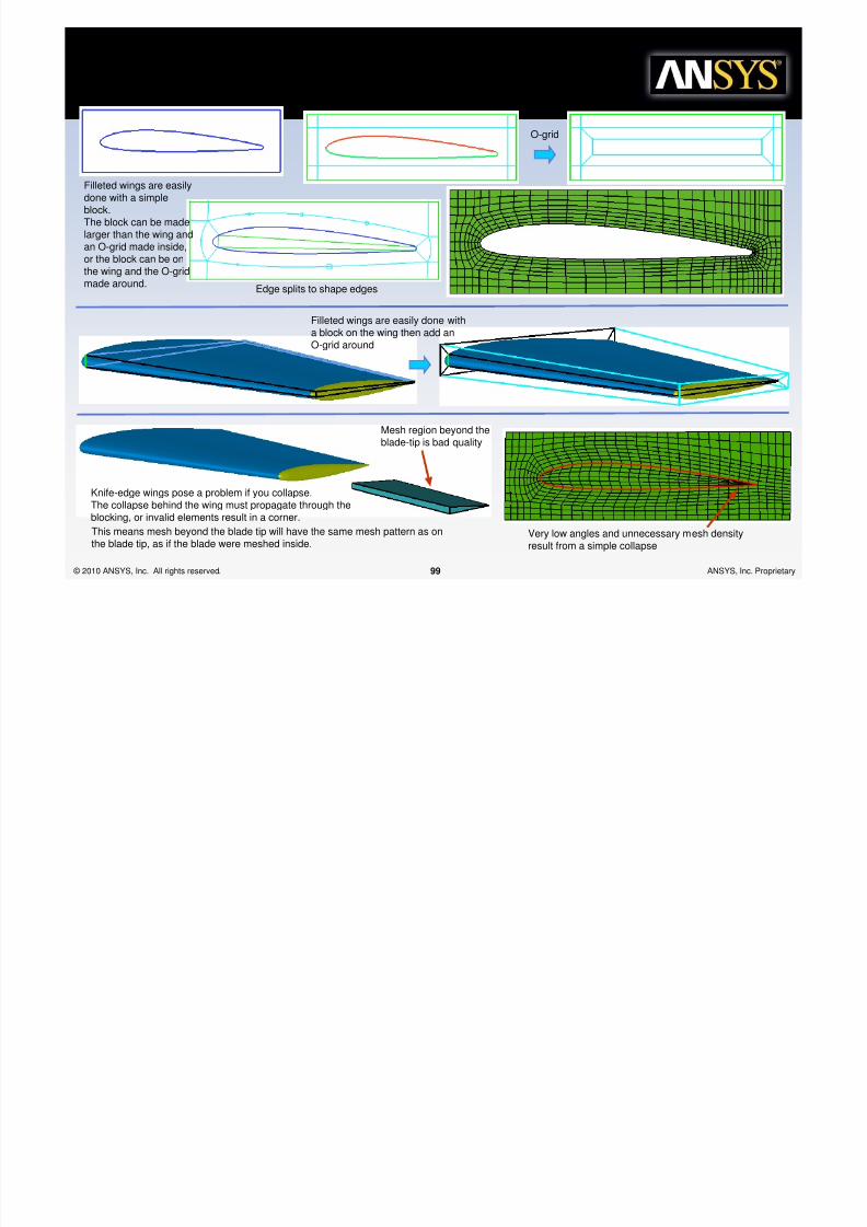
O-grid
8/10/2019 Icemcfd Tips&Tricks2010
http://slidepdf.com/reader/full/icemcfd-tipstricks2010 99/117
© 2010 ANSYS, Inc. All rights reserved. 99 ANSYS, Inc. Proprietary
Filleted wings are easilydone with a simpleblock.The block can be made
larger than the wing andan O-grid made inside,or the block can be onthe wing and the O-gridmade around.
Edge splits to shape edges
Filleted wings are easily done witha block on the wing then add an
O-grid around
Knife-edge wings pose a problem if you collapse.The collapse behind the wing must propagate through theblocking, or invalid elements result in a corner.
Mesh region beyond theblade-tip is bad quality
This means mesh beyond the blade tip will have the same mesh pattern as onthe blade tip, as if the blade were meshed inside.
Very low angles and unnecessary mesh densityresult from a simple collapse
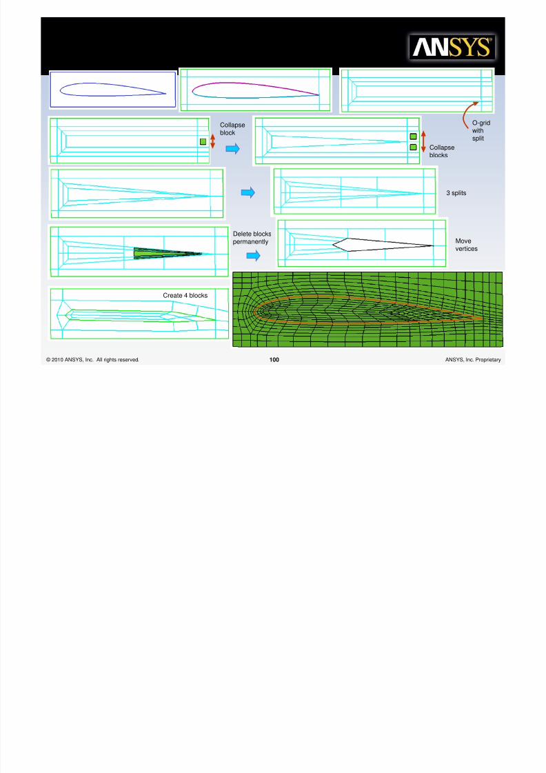
/asic /lock "%ruc%ures
8/10/2019 Icemcfd Tips&Tricks2010
http://slidepdf.com/reader/full/icemcfd-tipstricks2010 100/117
© 2010 ANSYS, Inc. All rights reserved. 100 ANSYS, Inc. Proprietary
Create 4 blocks
Collapseblocks
Collapseblock
Delete blockspermanently Move
vertices
3 splits
O-gridwithsplit
/asic /lock "%ruc%ures
A knife-edge blade can also be handledby collapsing all around the blade if the

8/10/2019 Icemcfd Tips&Tricks2010
http://slidepdf.com/reader/full/icemcfd-tipstricks2010 101/117
© 2010 ANSYS, Inc. All rights reserved. 101 ANSYS, Inc. Proprietary
by collapsing all around the blade if thecomplicated strategy of the previousexample is not wanted.
i l sHigh or low curvature, etc.
o' To

8/10/2019 Icemcfd Tips&Tricks2010
http://slidepdf.com/reader/full/icemcfd-tipstricks2010 102/117
© 2010 ANSYS, Inc. All rights reserved. 102 ANSYS, Inc. Proprietary
V a r i e t y o f A i r f o►May require different blocking strategy (Topology)
►Requires some robust scripting
o i l sTrailing edge?
o' To

8/10/2019 Icemcfd Tips&Tricks2010
http://slidepdf.com/reader/full/icemcfd-tipstricks2010 103/117
© 2010 ANSYS, Inc. All rights reserved. 103 ANSYS, Inc. Proprietary
V a r i e t y o f A i r f o►Blunt
►Deal with size transitions
►Sharp
►Collapse trailing edge block
l d sFar Fields
o' To

8/10/2019 Icemcfd Tips&Tricks2010
http://slidepdf.com/reader/full/icemcfd-tipstricks2010 104/117
© 2010 ANSYS, Inc. All rights reserved. 104 ANSYS, Inc. Proprietary
V
a r i e t y o f
F a r F i e l
►Square, round, half circle, Wedge etc.
►HGrid, OGrid, CGrid, YGrid, etc.
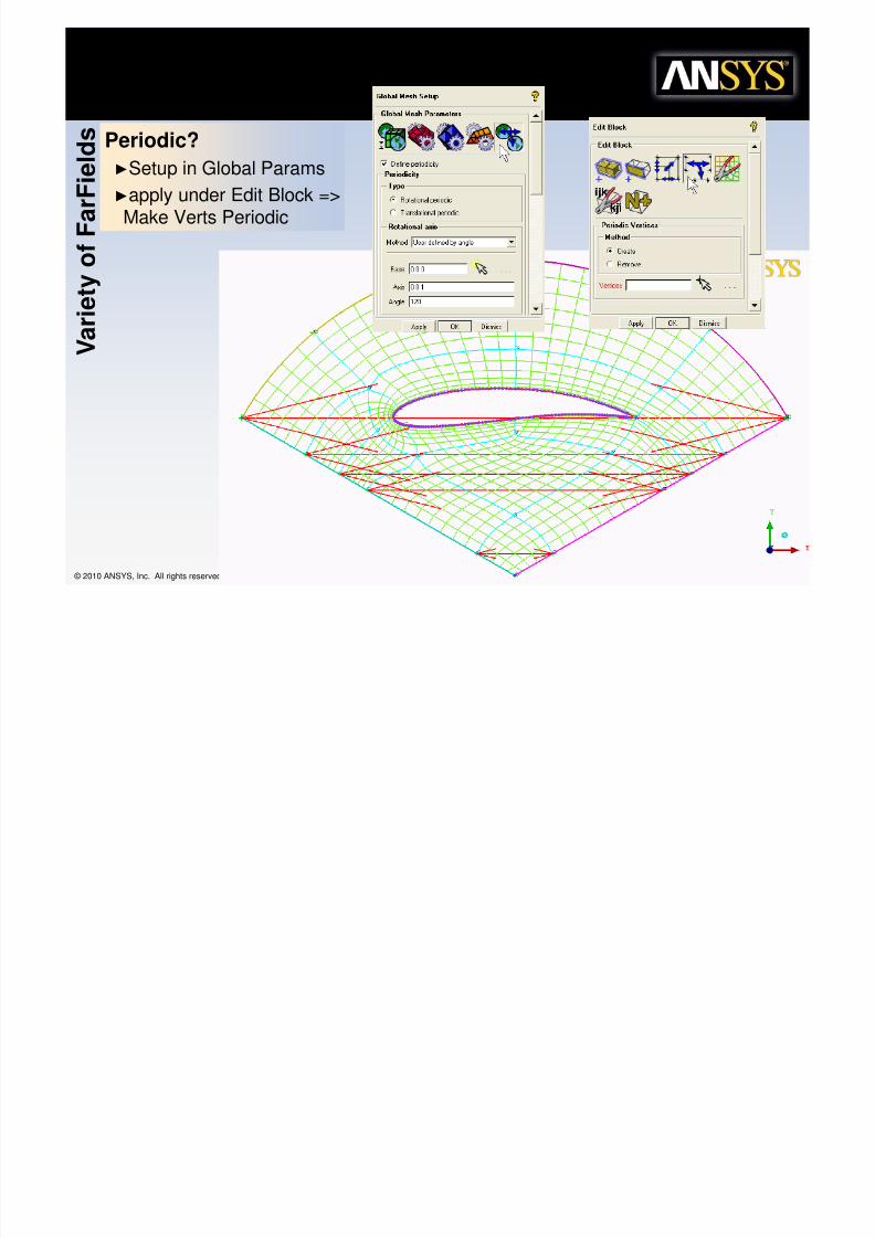
►Periodic?
Note: the FF scale hasbe dramaticallyreduced for illustration
8/10/2019 Icemcfd Tips&Tricks2010
http://slidepdf.com/reader/full/icemcfd-tipstricks2010 105/117
l d sPeriodic?A d Bl d B Bl d
o' To

8/10/2019 Icemcfd Tips&Tricks2010
http://slidepdf.com/reader/full/icemcfd-tipstricks2010 106/117
© 2010 ANSYS, Inc. All rights reserved. 106 ANSYS, Inc. Proprietary
V
a r i e t y o f
F a r F i e
►Around Blades or Between Blades
►Between Blades if NO Tip Gap
Channel between blades?
►Multi-Block with OGrid
►HGrid converted to a single output block
PeriodicV a
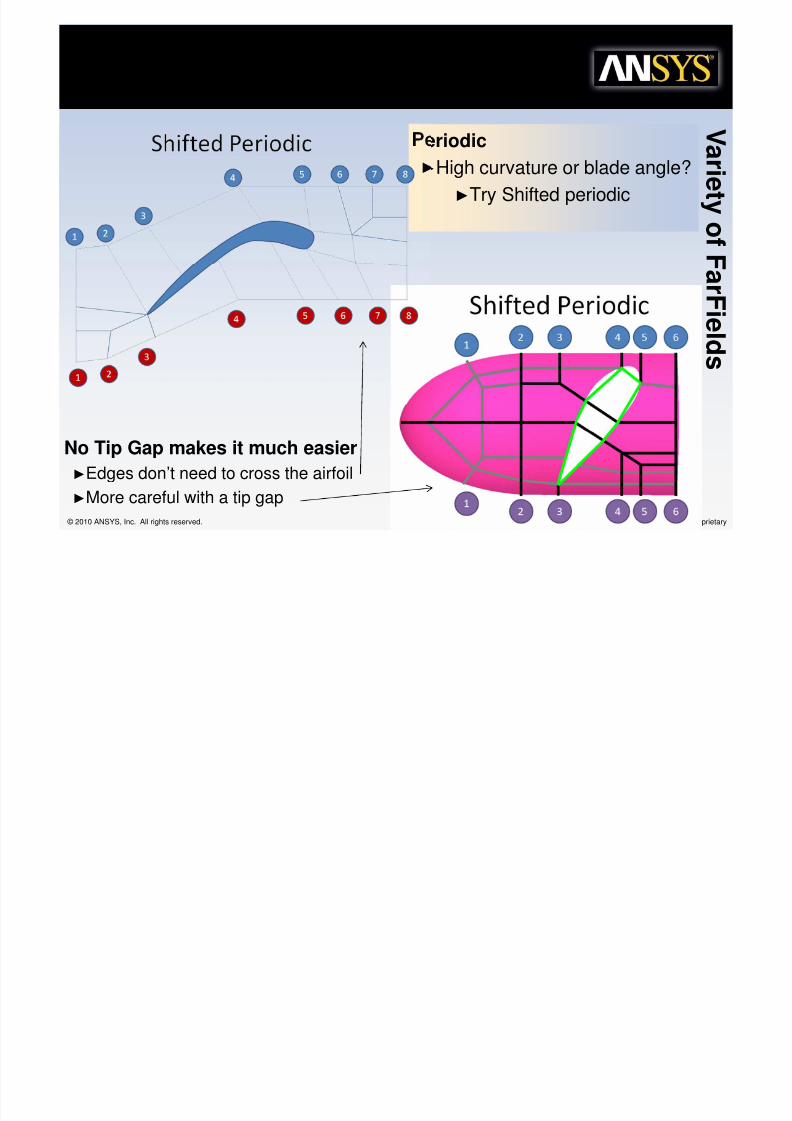
"hif%ed &eriodic…
8/10/2019 Icemcfd Tips&Tricks2010
http://slidepdf.com/reader/full/icemcfd-tipstricks2010 107/117
© 2010 ANSYS, Inc. All rights reserved. 107 ANSYS, Inc. Proprietary
►High curvature or blade angle?
►Try Shifted periodic
ar i e t y
of F ar F
i el d s
No Tip Gap makes it much easier
►Edges don’t need to cross the airfoil
►More careful with a tip gap
r%hogonali%, "+oo%her
• Improves volume transition• Equalizes angles between elements

8/10/2019 Icemcfd Tips&Tricks2010
http://slidepdf.com/reader/full/icemcfd-tipstricks2010 108/117
© 2010 ANSYS, Inc. All rights reserved. 108 ANSYS, Inc. Proprietary
Equalizes angles, smoothesvolume transitions, makes themesh orthogonal
• Equalizes angles between elements
• Can affect just the mesh or adjustblocking
• Saves time otherwise spent onadjusting edge parameters• Can be used to set orthogonal initial
height• Works on many mesh types
– Structured Multi-block Hexa– Unstructured Hexa– hexa dominant– BF-Cart– Hybrid mesh
r%hogonali%, "+oo%her
• Users run into trouble because not
8/10/2019 Icemcfd Tips&Tricks2010
http://slidepdf.com/reader/full/icemcfd-tipstricks2010 109/117
© 2010 ANSYS, Inc. All rights reserved. 109 ANSYS, Inc. Proprietary
all the mesh is supposed to beorthogonal
– Release orthogonality
• Also can use this to set initialheight off the wall
• Note: this may reduce min quality…Its goal is to improve transitionsand the overall quality of the mesh
E$%ended Meshing(
ICEM CFD In%erac%i5e

8/10/2019 Icemcfd Tips&Tricks2010
http://slidepdf.com/reader/full/icemcfd-tipstricks2010 110/117
© 2010 ANSYS, Inc. All rights reserved. 110 ANSYS, Inc. Proprietary
• Options under
MultiZone Method
Yes: Writes ICEM CFD Files for usein ICEM CFDInteractive: Runs interactiveICEM CFDBatch: Runs ICEM CFD in Batch
Using ICEM CFD Interactive w/replay control, user can blockout a mesh and commit it back to Meshing
Change model parameters, and run ICEM CFD inbatch to update parameter change
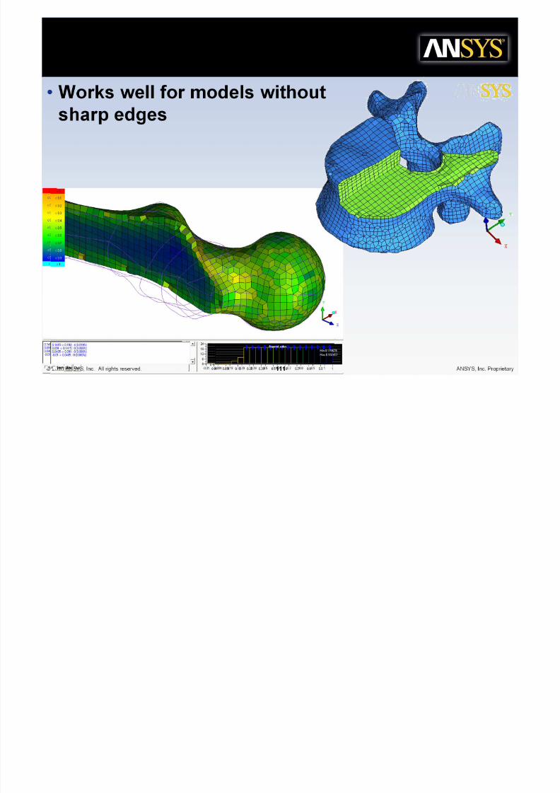
/F>Car%
• Works well for models withouth d
8/10/2019 Icemcfd Tips&Tricks2010
http://slidepdf.com/reader/full/icemcfd-tipstricks2010 111/117
© 2010 ANSYS, Inc. All rights reserved. 111 ANSYS, Inc. Proprietary
sharp edges

8/10/2019 Icemcfd Tips&Tricks2010
http://slidepdf.com/reader/full/icemcfd-tipstricks2010 112/117
Car%esian Mesh
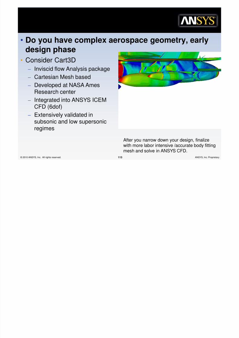
• Do you have complex aerospace geometry, earlyd i h
8/10/2019 Icemcfd Tips&Tricks2010
http://slidepdf.com/reader/full/icemcfd-tipstricks2010 113/117
© 2010 ANSYS, Inc. All rights reserved. 113 ANSYS, Inc. Proprietary
design phase
• Consider Cart3D
– Inviscid flow Analysis package
– Cartesian Mesh based
– Developed at NASA AmesResearch center
– Integrated into ANSYS ICEMCFD (6dof)
– Extensively validated insubsonic and low supersonicregimes
After you narrow down your design, finalizewith more labor intensive /accurate body fittingmesh and solve in ANSYS CFD.
"elf Training
*esources
"elf Training
*esources

8/10/2019 Icemcfd Tips&Tricks2010
http://slidepdf.com/reader/full/icemcfd-tipstricks2010 114/117
© 2010 ANSYS, Inc. All rights reserved. 114 ANSYS, Inc. Proprietary © 2010 ANSYS, Inc. All rights reserved. 114 ANSYS, Inc. Proprietary
"elf Training *esources

8/10/2019 Icemcfd Tips&Tricks2010
http://slidepdf.com/reader/full/icemcfd-tipstricks2010 115/117
© 2010 ANSYS, Inc. All rights reserved. 115 ANSYS, Inc. Proprietary
• ICEM CFD has many options.
– Flexibility, Power
– Harder to learn on yourown
• Ideally, you can get trainingfrom an instructor, but noteveryone has this option.
• Self training resources include
– Built in tutorials and Help
– Programmers Guide

8/10/2019 Icemcfd Tips&Tricks2010
http://slidepdf.com/reader/full/icemcfd-tipstricks2010 116/117
Thank,ou
• Thank you

8/10/2019 Icemcfd Tips&Tricks2010
http://slidepdf.com/reader/full/icemcfd-tipstricks2010 117/117
© 2010 ANSYS, Inc. All rights reserved. 117 ANSYS, Inc. Proprietary
Thank you
• Don’t forget to contact support for assistance
or advanced suggestions