Embed Size (px)
Citation preview

VERCO STEEL DECKS
VERCO MANUFACTURING CO.4340 NORTH 42ND AVENUEPHOENIX, ARIZONA 85019
1.0 SUBJECT
Verco Steel Decks
2.0 DESCRIPTION
The Verco steel decks described in this report comply withthe Specification for the Design of Cold-Formed SteelStructural Members, 1986 (with December 1989Addendum), as referenced in Division VII of the 1997Uniform Building Code™ (UBC), and the Specification forthe Design of Cold-Formed Steel Structural Members, 1996edition, as referenced in Section 2205 of the 2000International Building Code® (IBC).
2.1 Deck Types:
2.1.1 General: The decks are cold-formed from steelsheets with galvanized, primer-painted, or mill finishes. Allgalvanizing shall comply with ASTM A 924. A suffix numberindicates a deck cover width—for example, B-24 indicatesa deck cover width of 24 inches (610 mm). The suffix “SS”indicates deck provided with extended female lip.
2.1.2 Types PLB, HSB, HSB-CD, PLN, N, and N-24CDRoof Decks, and PLB, B, BCD, BR, PLN, N, NCD, PLW2,W2, W2CD, PLW3, W3, and W3CD Formlok Decks: Thedecks are available as galvanized, primer-painted, or mill-finished. Galvanized steel decks shall be formed fromASTM A 653, SS Grade 33 (minimum), steel, while theprimer-painted and mill-finished steel decks shall be formedfrom either ASTM A 611, Grade C (minimum), steel; ASTMA 1008, SS Grade 33 (minimum), steel; or ASTM A 1008HSLAS, Class 1 or Class 2, Grade 45 (minimum), steel. Allsteels have a minimum yield strength of 38,000 psi (262MPa).
2.1.3 15/16-inch Vercor and 15/16-inch Vercor VentlokDecks: The decks are galvanized steel formed from steelcomplying with ASTM A 653, SS Grade 80, with a minimum80,000 psi (551 MPa) yield strength; or primer-painted ormill-finished steel that complies with ASTM A 611, Grade E,or ASTM A 1008, SS Grade 80, with a minimum yieldstrength of 80,000 psi (551 MPa).
The Vercor galvanized decks are permitted to be used fordiaphragm purposes when a lightweight concrete fill,having a minimum 2-inch (51 mm) depth above the topflute, is applied. The lightweight concrete must conform tothe following specifications:
1. Oven-dry weight, 25 to 30 pounds per cubic foot (400 to480 kg/m3).
2. One-to-six mix by volume of cement to aggregate.
3. Aggregate shall comply as a Group I aggregate perASTM C 332.
4. The lightweight concrete must be tested in accordancewith “Tests of Compressive Strength of LightweightInsulating Concrete,” ASTM C 495, and must have a 3-inch-diameter-by-6-inch-high (76 mm by 152 mm)cylinder compressive strength of at least 140 poundsper square inch (965 kPa).
Vercor deck, when formed from galvanized steel, primer-painted or mill-finished, is permitted as a diaphragm withoutconcrete fill as described in Table 29.
2.1.4 PunchLok™ System: The PunchLok™ systemconsists of PLB and PLN roof decks and PLB, PLN, PLW2,and PLW3 Formlok decks connected at sidelaps with theVerco Manufacturing Co. proprietary connection. TheVerco sidelap connection, referred to as the VSC, is aninterlocking connection between the male and female lipsof the decks listed above. The VSC connection ispermitted to be made in either direction relative to thefemale lip. An acceptable VSC connection has been madewhen the sidelap material has been sheared and offset sothe sheared surface of the steel deck male leg is visible.This punched portion measures 5/8 inch (15.9 mm) nominalwidth by 3/8 inch (9.5 mm) nominal height. The PunchLok™systems must be installed in accordance with Vercoinstructions. The resulting VSC connection is illustrated inFigure 11.
Allowable diaphragm shears and flexibility factors forPLW2 and PLW3 Formlok deck without concrete and withsidelaps connected with the VSC connections are shown inTables 15 and 17.
Allowable diaphragm shears and flexibility factors for PLBand PLN roof or Formlok deck without structural concretefill, using sidelaps connected with the VSC connections, areshown in Tables 19 and 24. The ends of the PLB and PLNdeck shall be lapped a minimum of 2 inches (51 mm).
2.1.5 PLB™-36 Deck with the PunchLok™ SystemFastened with Hilti Pins: This system consists of PLB-36deck fastened to the structural supports with Hilti X-EDN19-THQ12 or X-EDNK22-THQ12 power-actuated fasteners.Deck sidelaps shall be connected with the VSCconnections described in Section 2.1.4. The ends of thePLB-36 deck shall be lapped a minimum of 2 inches (51mm).
Fasteners connecting the deck to structural steelsupports shall be centered not less than 1 inch (25 mm)
are not to be construed as representing aesthetics or any other attributes not specifically addressed, nor are they to be construed as
an endorsement of the subject of the report or a recommendation for its use. There is no warranty by ICBO E valuation Service, Inc., express or implied,
as to a ny find ing or other ma tter in this repo rt, or a s to an y pro duc t cove red b y the r epo rt.
Copyright © 2002 Page 1 of 8
ER-2078P
Reissued December 1, 2002
ICBO Eva luat ion Service, Inc. • 5360 W orkman M ill Road, W hit t ier , Califo rn ia 90601 • www.icboes .org
Filing Category: ROOF, WALL AND FLOOR PANELS—Steel

Page 2 of 8 ER-2078P
from the ends of the sheets. The Hilti fasteners have adome-style head and a 15/32-inch-diameter (11.8 mm) steelflat washer and a steel top-hat washer. The X-EDN19-THQ12 fastener has a brass-colored top-hat washer, andthe X-EDNK22-THQ12 fastener has a silver-colored top-hatwasher. All fasteners have an electroplated zinc coating.ICBO ES evaluation report ER-4373 has additionalinformation on the Hilti fasteners.
Allowable diaphragm shears and flexibility factors forPLB-36 roof deck fastened to supports with Hilti X-EDN19-THQ12 or X-EDNK22-THQ12 fasteners, with sidelapsconnected with the VSC connections, are shown in Table27. The appropriate Hilti fastener is selected based on theactual substrate thickness, with the tabulated valuesadjusted as noted in the table footnotes. Allowable tensionloads for the Hilti fasteners are shown in Table 2. Properpenetration of the Hilti fasteners into structural supports isshown in Figure 7.
2.1.6 PLB™-36 Deck with the PunchLok™ SystemFastened with Pneutek® Pins: This system consists ofPLB-36 deck fastened to the structural supports withPneutek SDK61075, SDK63075, K64062, K66062, orK66075 fasteners. Deck sidelaps are connected with theVSC connections described in Section 2.1.4. The ends ofthe PLB-36 deck shall be lapped a minimum of 2 inches(51 mm).
Fasteners connecting the deck to structural steelsupports shall be centered not less than 1 inch (25 mm)from the ends of the sheets. The Pneutek fasteners have1/2-inch-diameter (12.7 mm) heads. All fasteners aremechanical zinc or zinc electro-chromate plated. SeeICBO ES evaluation report ER-3829 for additionalinformation on the Pneutek fasteners.
Allowable diaphragm shears and flexibility factors forPLB-36 roof deck fastened to supports with PneutekSDK61075, SDK63075, K64062, K66062, or K66075fasteners, with sidelaps connected with the VSCconnections, are shown in Table 28. The appropriatePneutek fastener is selected based on the actual substratethickness as noted in the table headings. Allowable shearvalues for Pneutek fasteners installed parallel to deck flutesand allowable tension loads are shown in Table 3.Fasteners must be driven such that there is tight contactbetween the fastener head and the attached panels. SeeFigure 8.
2.1.7 SHEARTRANZ® II: The system consists of No. 14gage [0.070 inch (1.78 mm)] ShearTranz II-42 or No. 16gage [0.0598 inch (1.52 mm)] ShearTranz II restrainingelements, which are formed from steels, described inSection 2.1.2, with a minimum yield strength of 33,000 psi(228 MPa). The No. 14 gage ShearTranz II-42 units areused with PLB-36 decks, and the No. 16 gage ShearTranzII units are used with HSB-36 decks at shear collectingsupport elements perpendicular to the deck corrugations.No skewing of deck to collector supports is permitted. Inaddition to the standard details, the conditions describedbelow may require the SHEARTRANZ II-42 orSHEARTRANZ II elements.
The first condition occurs with decks cantilevered overdeck supports. In this condition, the SHEARTRANZ II-42 orSHEARTRANZ II element is installed as shown in Figure 5.
The second condition occurs when the deck ends abut atinterior supports. In this condition, the top flanges ofSHEARTRANZ II-42 or SHEARTRANZ II elements are
centered over the butt joints. Allowable diaphragm shearsand flexibility factors for ShearTranz II-42 and PLB-36 deck,with sidelaps connected with the VSC connection, areshown in Table 21. Allowable diaphragm shears andflexibility factors for ShearTranz II and HSB-36 deck withbutton punched or top seam welded sidelaps are shown inTable 22. Installation details are shown in Figure 5.
2.1.8 SHEARTRANZ®: This system consists of a specialend support connection weld with No. 16 gage [0.0598 inch(1.52 mm)] Z- or channel-shaped sections for use withN-24, HSB-30 or HSB-36 decks. The sections shall beformed from steels described in Section 2.1.2 of this report,with a minimum yield strength of 33,000 psi (228 MPa).The SHEARTRANZ® element is used only at shearcollecting members perpendicular to the corrugations. Allend laps at supports must be at least 2 inches (51 mm) andfastened to supports with arc spot puddle welds, asrequired by design. Details are shown in Tables 23 and 26and in Figure 6.
2.1.9 System 80: This system consists of galvanizedHSB-30 or HSB-36 steel decks, SHEARTRANZ elementand one of the lightweight concrete systems in Item 1 orItem 2 below. Where required, positive venting of the HSB-30 and HSB-36 deck is accomplished through use of eitherVentlok-type deck or vent tabs in the interior bottom flangesof the deck, spaced 6 inches (152 mm) on center. Thelightweight concrete systems are:
1. Zonolite insulating concrete with or without Insulpermboard, constructed according to ICBO ES evaluationreport ER-3260.
2. Lightweight insulating concrete complying withspecifications in Section 2.1.3 of this report.
Allowable diaphragm shear values are presented in Table30.
2.1.10 Acoustical Deck: PLB, HSB, PLN, and N types areavailable as acoustical deck. See Figure 2 for perforationpatterns. Data in Tables 19 thru 28 also apply to theacoustical versions. Acoustical uses are limited to nonfire-resistive assemblies.
2.1.11 Acoustical Cellular Deck: HSB-CD and N-24CDroof decks and BCD, NCD, W2CD, and W3CD Formlokdecks are available with acoustical perforations in the flatbottom plate. Perforations are 5/32 inch (4mm) in diameteron 7/16-inch (11.1 mm) staggered centers. The nominalwidths of the perforated bands, which are centered underthe top flanges of the fluted top sections, are: HSB-CD/BCD—3.6 inches (91 mm); N-24CD/NCD—5.5 inches(140 mm); W2CD and W3CD—6.7 inches (170 mm).
2.2 Design:
2.2.1 General: Section properties and minimum designbase-metal thicknesses are shown in Tables 4 and 6, anddeck profiles are shown in Figures 1 and 3.
The tables accompanying this report describe allowablediaphragm shear values for each roof and composite decktype and superimposed loads for each composite decktype. The General Notes on the tables provide additionalinformation.
Allowable tension for arc spot welds is determined byEquation E2.2-8 or Equation E2.2.2-1 of the AISISpecification for the Design of Cold-Formed SteelStructural Members (AISI), referenced in the applicablecode.

Page 3 of 8 ER-2078P
Allowable tension loads for Hilti X-EDN19-THQ12 or X-EDNK22-THQ12 fasteners are shown in Table 2. Allowabletension loads for Pneutek SDK61075, SDK63075, K64062,K66062, and K66075 fasteners are shown in Table 3.
Allowable tension loads for the ITW/Buildex TRAXX 3, 4and 5 and TEKS 3, 4 and 5 self-drilling screws with 0.415-inch-diameter (10.5 mm) washer heads, using 15/16-inch (33mm) Vercor deck, are as noted in Footnote 7 of Table 29.
2.2.2 Concrete Diaphragms with Shear Connectors:Concrete diaphragms with shear connector studs may beused with Types PLB, B, BR, BCD, PLW2, W2, W2CD,PLW3, W3, W3CD, PLN, N, NCD and 15/16-inch Vercordeck types. Details are shown in Table 14. Deck flutes areperpendicular to steel supports. Shear connector studs mayreplace required arc spot welds.
2.2.3 Composite Decks for Floors and Roofs: Thesedecks are of the same material and finish as describedabove, but with various depths of concrete as set forth inthe accompanying tables, and with web and flangeembossments designated as Formlok.
Concrete is made with normal-weight rock or expandedshale aggregates and must have a minimum 28-daycompressive strength of 3,000 psi (20.7 MPa). Theminimum concrete fill thickness is 2 inches (51 mm) abovethe top of the steel deck.
The deck types used with concrete fill are as follows:
1. Types PLB-36 and B-36, BCD, and BR-24, -30, and -36Formlok.
2. Types PLN-24 and N-24 and NCD Formlok.
3. Types PLW2-36, W2-36, W2CD, PLW3-36, W3-36,and W3CD Formlok.
Where bearing lengths at reaction points of decks do notcomply with minimum values in Table 5, separate analysisfor web crippling is required in accordance with Section2230-C3.4 of the applicable AISI. Requirements in Table 5apply to bare decks and to composite decks during theconstruction phase only, prior to the concrete’s acquiringminimum compressive strength.
2.3 Installation:
Arc seam or arc spot (puddle) welds for field assembly ofsteel decking must have an effective fusion area of at least3/8 inch by 1 inch (9.5 mm by 25 mm) or 1/2 inch (12.7 mm)in diameter, respectively. Seam welds are a minimum of11/2 inches (38 mm) long. Minimum E60XX filler metal isused. Other weld requirements must comply with AWS D1.3-98. Connections using the PunchLokTM system aredescribed in Sections 2.1.4 to 2.1.7.
2.4 Restrained Fire-resistive Ratings:
2.4.1 Conditions of Restraint: Interior spans ofcontinuous composite slabs may be considered thermallyrestrained. For other conditions, evidence substantiatingadequate thermal restraint, consistent with Section 703.2of the UBC or Section 703.2.3 of the IBC, whichever isapplicable, must be submitted to and approved by thebuilding official.
2.4.2 Vercor, Vercor Ventlok, PLB, B, PLN, N, PLW2,and W2: Types Vercor, Vercor Ventlok, PLB, B, PLN, N,PLW2, and W2 decks are permitted to be used for a two-hour fire-resistive roof deck with exposed soffit, subject tothe following conditions:
1. The fill type, thickness and construction are as set forthin Table 7-C of the UBC or Table 719.1(3) of the IBC,whichever is applicable.
2. The maximum clear span for No. 26 gage decks shallbe limited to 6 feet, 8 inches (2032 mm), and forheavier gage decks to 8 feet, 6 inches (2590 mm).
3. The decks are attached to support structural elementsas set forth in the tables accompanying this report.
2.4.3 PLB, B, BCD, BR, PLN, N, NCD, PLW2, W2,W2CD, PLW3, W3, and W3CD Formlok: Types PLB, B,BCD, BR, PLN, N, NCD, PLW2, W2, W2CD, PLW3, W3,and W3CD Formlok, when used with a structural concretefill, shall have a two-hour fire-resistive rating with exposedunderside when used as either a roof or floor, provided:
1. The maximum clear spans for PLB, B, BCD, and BRFormlok are limited to 12 feet (3658 mm), while thespans for PLW2, W2, W2CD, PLW3, W3, W3CD, PLN,N, and NCD Formlok are limited to 13 feet, 2 inches(4013 mm).
2. The minimum steel gage shall be No. 22 for fluted unitsand No. 20/20 for cellular units. Unit finishes may begalvanized, phosphatized/painted, or mill-finished.
3. No electrical raceways are placed in the concrete fill.
4. The minimum attachments are as follows:
a. All welds at each support shall be 1/2-inch (12.7 mm)effective diameter arc spot (puddle) welds asrequired for diaphragm shears, but there shall be atleast four welds for 30- and 36-inch-wide (762 and914 mm) PLB, B, and BCD decks; three welds for24-inch-wide (610 mm) decks; and one in eachvalley for PLW2, W2, W2CD, PLW3, W3, andW3CD Formlok decks.
Where arc spot welds and shear studs coincide,the arc spot weld may be eliminated.
b. Attachment to chords or struts shall be welds asrequired for diaphragm shear with concrete fill.
c. Sidelaps (seams) shall be button punched orwelded at 3 feet (914 mm) on center, maximum.Sidelaps of PLB, PLN, PLW2, and PLW3 decks arepermitted to be connected with the VSCconnections described in Section 2.1.4 at 3 feet(914 mm) on center, maximum. For BR decks, usea 11/2-inch (38 mm) seam weld at 3 feet (914 mm)on center.
5. The concrete fill thickness above the deck top flangemust be either 31/4 inches (82 mm) for structurallightweight concrete having a unit weight of 110 ± 3pounds per cubic foot (1762 ± 48 kg/m3) and a 28-daycompressive strength of 3,000 psi (20.7 MPa); or 41/2
inches (114 mm) for normal-weight concrete having aunit weight of 150 ± 3 pounds per cubic foot (2403 ± 48kg/m3) and a 28-day compressive strength of 3,500 psi(24.1 MPa).
6. The concrete fill is reinforced with minimum 6-by-6,W1.4-by-W1.4 welded-wire fabric, placed near thecenter of the concrete fill.
2.4.4 Additional Fire-resistive Ratings:
1. The following are additional restrained fire-resistiveratings for Types PLB, B, BCD, BR, PLN, N, NCD,PLW2, W2, W2CD, PLW3, W3, and W3CD Formlokdecks:

Page 4 of 8 ER-2078P
a. One-hour rating with 21/2 inches (63.5 mm) of 3,000psi (20.7 MPa) lightweight [110 pcf (1762 kg/mm3)]structural concrete, or 31/2 inches (89 mm) of 3,500psi (24.1 MPa) normal-weight [150 pcf (2403 kg/mm3)] concrete over top flute of deck.
b. Three-hour rating with 41/4 inches (108 mm) of3,000 psi (20.7 MPa) structural lightweight [110 pcf(1762 kg/mm3)] concrete over top flute of deck.
2. One- and two-hour restrained fire-resistive ratings forsteel decking with Zonolite insulating concrete, with orwithout Insulperm insulation board, are described incurrent ICBO ES evaluation report ER-3260.
2.5 Unrestrained Fire-resistive Ratings:
2.5.1 PLB, B, BCD, BR, PLN, N, NCD, PLW2, W2,W2CD, PLW3, W3, and W3CD Formlok: Types PLB, B,BCD, BR, PLN, N, NCD, PLW2, W2, W2CD, PLW3, W3,and W3CD Formlok, when used with a structural concretefill, have a fire-resistive rating with exposed underside as afloor or roof deck, provided:
1. The minimum steel gage shall be No. 22 for fluted unitsand No. 20/20 for cellular units.
2. Decks are attached as follows:
a. All welds at supports shall be 1/2-inch (12.7 mm)effective diameter arc spot (puddle) welds asrequired for diaphragm shears, but there shall be atleast four welds for 30- and 36-inch-wide (762 and914 mm) PLB, B, and BCD; three welds for 24-inch-wide (610 mm) decks; and one in each valley forPLW2, W2, W2CD, PLW3, W3, and W3CDFormlok decks.
b. Attachment to chords or struts must be welds asrequired for decks with concrete fill to resist thediaphragm shear.
c. Sidelaps (seams) shall be button punched orwelded at 3 feet (914 mm) on center, maximum.Sidelaps of PLB, PLN, PLW2, and PLW3 decksshall be connected with the VSC connectionsdescribed in Section 2.1.4 at 3 feet (914 mm) oncenter, maximum. For BR decks, 11/2-inch (38 mm)seam welds at 3 feet (914 mm) on center shall beused.
3. The concrete fill must be structural lightweight concretewith expanded shale or slate aggregate and 4 to 7percent entrained air. The unit weight of the concretemust be 110 pounds per cubic foot (1,762 kg/m3), witha minimum 28-day compressive strength, fNc, of 3,000psi (20.7 MPa). The thickness above the top flange ofthe deck is 31/4 inches (82 mm).
4. The unrestrained assembly is assigned the same fire-resistive rating as the fire-resistive rating of thesupporting steel beams, or a lesser rating.
2.5.2 Steel Decking with Zonolite: One-hour and two-hour unrestrained fire-resistive ratings for steel decking withZonolite insulating concrete, with or without Insulperminsulation board, are described in current ICBO ESevaluation report ER-3260.
2.5.3 Fireproofing Spray-applied to Deck: Fire-resistiveratings with fireproofing material spray-applied togalvanized deck underside are described in current ICBOES evaluation reports ER-1244, ER-4607 and ER-4818. In
addition, prime-painted Types PLB, B, BR, PLN, N, PLW2,W2, PLW3, and W3 decks can be sprayed with MK-6(ICBO ES evaluation ER-4607), DC/F (ICBO ES evaluationreport ER-1244) or CAFCO 300 (ICBO ES evaluation reportER-4818) fireproofing materials.
2.5.4 Steel Deck, Spray-applied Fireproofing andConcrete Fill: Fire-resistive ratings with Verco steel deck,spray-applied fireproofing and concrete fill are achievedwith Fibermesh fibers substituted for welded-wire fabric inaccordance with ICBO ES evaluation report ER-4811.
2.6 Special Inspection:
2.6.1 Concrete: Special inspection for concrete andconcrete reinforcement is in accordance with Sections1701.1 and 1701.4 of the UBC or Section 1704.4 of theIBC, whichever is applicable. The inspector’s duties includesampling and testing, and verification of concrete mixes,reinforcement types and placement, and concreteplacement.
2.6.2 Welding: Special inspection for welding is inaccordance with Section 1701.5 of the UBC or Section1704.3 of the IBC, whichever is applicable. Beforeproceeding, the welder must demonstrate his ability toproduce the prescribed weld to the special inspector’ssatisfaction. The inspector’s other duties include verificationof materials, weld preparation, welding procedures andwelding processes.
2.6.3 Additional Requirements for Installations underthe IBC:
2.6.3.1 Periodic Special Inspections: Periodic specialinspections in accordance with Section 1707.4 of the IBCare required where the steel deck systems are used as partof a seismic-force-resisting system in structures assignedto Seismic Design Category C, D, E, or F. Periodic specialinspections apply to connections such as screws, poweractuated fasteners, Verco sidelap connections and buttonpunches. Periodic special inspections also apply wherenoted in Tables 1704.3 and 1704.4 of the IBC.
2.6.3.2 Continous Special Inspections: Continuousspecial inspections apply where noted in Tables 1704.3and 1704.4 of the IBC.
2.6.3.3 Quality Assurance Plan: A quality assuranceplan must be submitted to the building official as set forthin Sections 1705 and 1706 of the IBC. The plan mustinclude the special inspection duties noted in Section 2.6.1and 2.6.2.
2.7 Identification:
Each bundle of decking is marked with the VercoManufacturing Co. name, the deck type, the gage, and theevaluation report number (ICBO ES ER-2078P).SHEARTRANZ® p ieces a re s tamped wi th“SHEARTRANZ®,” SHEARTRANZ® II-42 pieces arestamped “SHEARTRANZ II-42”, and SHEARTRANZ® IIpieces are stamped “SHEARTRANZ II.” All Sheartranzpieces also are labeled with the Verco Manufacturing Co.name and the evaluation report number (ER-2078P). Hilti,Pneutek, and ITW fasteners are identified in accordancewith ER-4373, ER-3829 and ER-3056, respectively.
3.0 EVIDENCE SUBMITTED
Data in accordance with the ICBO ES Acceptance Criteriafor Steel Decks (AC43), dated January 2002.

Page 5 of 8 ER-2078P
4.0 FINDINGS
That the Verco Steel Decks described in this reportcomply with the 1997 Uniform Building Code™ and the2000 International Building Code® for use as wall, floorand/or roof systems to resist vertical and horizontalforces, subject to the following conditions:
4.1 Composite sections are not used for loads thatare predominantly vibratory.
4.2 Where used as diaphragms:
4.2.1 The one-third stress increase (or 0.75reduction of the resulting forces) permitted forAllowable Stress Design in the building codefor load combinations containing wind orseismic forces shall not be used for shearvalues in the diaphragm tables.
4.2.2 Allowable shear values are as set forth in thetables accompanying this report for the type ofdeck involved.
4.2.3 Diaphragm deflections shall not exceed thepermitted relative deflections of walls betweenthe diaphragm level and the floor below. Theflexibility limitations shown in Table 7 may beused as a guide in lieu of a rational analysis ofthe anticipated deflections.
4.2.4 Diaphragms may be zoned by varying deckgage and/or connections across a diaphragmto meet varying shear and flexibility demands.
4.3 Vertical load design without a concrete fill isbased on the section properties in Tables 4 and 6of this report. Allowable reaction based on webcrippling is based on Table 5 of this report.
4.4 Special inspection is provided in accordance withSection 2.6.
4.5 Fire-resistive assemblies are assumed to beunrestrained unless evidence substantiatingadequate thermal restraint is submitted to andapproved by the building official. See Section2.4.1.
4.6 The decks are manufactured and installed inaccordance with this report.
4.7 Allowable loads and deflections are as set forth inthis report. Calculations demonstrating that theapplied loads comply with this report shall besubmitted to the building official for approval.
This report is subject to re-examination in two years.

Page 6 of 8 ER-2078P
General Notes: The following notes apply to all of the accompanying tables dated December 1, 2002, unless otherwise noted:
1. The allowable values for composite decks shown in the tables are applicable to either phosphatized/painted or galvanizeddecks, and the allowable values shown for roof decks are applicable to either painted, mill-finished, or galvanized decksunless specifically noted.
2. The allowable diaphragm shears listed in the tables are in pounds per linear foot.
3. The base-metal thickness for all decks is indicated in Tables 4 and 6. Thickness tolerances for all decks and Sheartranzelements shall comply with Section A3.4 of the AISI.
4. Deck panel sidelaps (seams) may be connected with the PunchLok™ VSC connections, welds, or button punches, asindicated in the evaluation report. The length of seam welds shall be a minimum of 11/2 inches (38 mm). The standing seamjoint, where required, shall be fastened at 3 feet (914 mm) on center, maximum.
Deck panel sidelaps (seams) may be fastened with self-tapping, self-drilling steel screws in place of button punches withoutaffecting the shear and flexibility factors, under the following conditions:
a. The screw size is minimum No. 10, with a minimum 3/4-inch (19.1 mm) length.
b. The screw spacing is identical to the tabulated button-punch spacing.
c. The deck material thickness is at least No. 22 gage (0.0276 inch base-metal thickness).
5. Arc seam or arc spot (puddle) welds shall have an effective fusion area to supporting members at least equivalent to 3/8 inch(9.5 mm) wide by 1 inch (25 mm) long, or 1/2 inch (12.7 mm) in diameter.
6. End attachment patterns for the Types PLB, B, BCD, BR, HSB, PLN, N, NCD, PLW2, W2, W2CD, PLW3, W3, and W3CDare shown below. See Tables 31 and 32 for 15/16-inch Vercor and 15/16-inch Vercor Ventlok deck end welds. See Figure 5for SHEARTRANZ II-42 and SHEARTRANZ II, Figure 6 for SHEARTRANZ and System 80, and Figure 9 for 15/16-inch Vercorfastened with screws.

Page 7 of 8 ER-2078P
7. Spacing of attachments to collector elements parallel to flutes:
a. Arc spot puddle welds to members such as chords and to collector elements such as struts or ties shall have a spacingin feet (mm) equal to 35,000(t) ÷ v [For Sl: 6,130(t) ÷ v],
where:
t = Uncoated steel thickness of fluted deck, in inches (mm).
v = Actual diaphragm shear at boundary supports or actual shear transferred to collector (at struts or ties), in poundsper foot (N/mm). Allowable diaphragm shear values in pounds per foot are set forth in Table 1.
b. Fillet welds are permitted to be used to attach the diaphragm to parallel members such as diaphragm chords, struts,ties, or other collector elements. Allowable capacity of fillet welds is determined in accordance with Section 2.2.2 ofAWS D1.3-98. Spacing of the welds shall be based on the actual shear to be transferred.
c. The spacing of Hilti fasteners at collectors parallel to deck flutes shall be the same as the spacing of the sidelapconnections. If the required shear transfer between the deck and an interior collector element parallel to the deck flutesexceeds the shear strength of the diaphragm, two Hilti fasteners shall be spaced the same as the sidelap fasteners.
d. Pneutek fasteners are permitted to be used to attach the diaphragm to parallel members such as diaphragm chords,struts, ties or other collector elements, with spacing based on the allowable shear strength of the specific fastener,substrate thickness, and deck gage combination used.
e. The attachment spacing is 3 feet (914 mm), maximum.
8. For attachments at interior lines of shear transfer perpendicular to deck corrugations: The shear transfer from a diaphragmto interior tie or strut lines perpendicular to deck corrugations shall not exceed the shear values indicated in the tables. Twolines of connections of the type appropriate to the table (welds, pins, ShearTranz II-42, ShearTranz II, or ShearTranz) maybe used to develop the actual shear transfer to these collector elements.
9. Where individual panels are cut, the partial panel shall be fastened in a manner to fully transfer the shears at the point of thediaphragm to the adjacent full panels for the values specified in the tables.
10. The minimum 28-day compressive strength for structural concrete shall be 3,000 psi (20.7 MPa), and unit weight shall beas indicated in the tables. The minimum depth of concrete shall be 2 inches (51 mm) over the top flange, and it is reinforcedwith a minimum 6-by-6, W1.4-by-W1.4 welded-wire fabric. The reinforcement shall be placed near the center of the fill overthe top flange. Where concrete fill depth exceeds 31/4 inches (82 mm), welded-wire fabric with an area equal to 0.00083 timesthe area of concrete fill over the metal deck, is required.
11. All decks with structural concrete fill may be considered rigid diaphragms (F#1). Table 7 describes flexibility categories.
12. For decks with structural concrete fill, the diaphragm shear values and flexibility factors apply to deck sections with or withoutembossments.
13. For decks with structural concrete fill, the diaphragm shear values and flexibility factors apply whether or not the sidelaps areattached.
14. For SI dimensions, the following conversions apply:
1 inch = 25.4 mm; 1 Ibf/ft = 14.6 N/m = 0.0146 N/mm; 1 in2 = 645.16 mm2; 1 in3 = 16 387.06 mm3; 1 in4 = 4 162 314 mm4;1 psi = 6.89 kPa; 1 ft = 3048 mm; 1 pcf = 16,018 kg/m3; 1 psf = 0.0479 kN/m2; 1 Ibf = 4.45 N.
Page 8 of 8 ER-2078P
FIGURE 11

Page 1 of 57 Report ER-2078P
December 1, 2002
Table of Contents
TABLE TOPIC PAGE
General
1 Allowable Shear Values - Spot or Seam Welds 2
2 Allowable Tension Loads - Hilti Fasteners . . . . 2
3 Allowable Shear and Tension Values - Pneutek
Fasteners . . . . . . . . . . . . . . . . . . . . . . . . . . . 2
4 Section Properties . . . . . . . . . . . . . . . . . . . . . . . 3
5 Allowable Reactions - Web Crippling . . . . . . . . 3
Figure 1 - Deck Profiles . . . . . . . . . . . . . . . . . . . 4
Figure 2 - Acoustical Deck . . . . . . . . . . . . . . . . 4
6 Cellular Deck - Properties and Capacities . . . . . 5
Figure 3 - Cellular Deck Resistance Welds . . . . 5
7 Diaphragm Flexibility Limitations . . . . . . . . . . . . 6
Com posite Decks w ith Concrete
(Vertical Loads and Diaphragm Shear Values)
8 PLB and B FORMLOK . . . . . . . . . . . . . . . . . . . . 7
9 BR FORMLOK - Superimposed Loads . . . . . . . 13
10 BR FORMLOK - Diaphragm Shear Values . . . . 14
11 PLW2 and W2 FORMLOK . . . . . . . . . . . . . . . . 16
12 PLW3 and W3 FORMLOK . . . . . . . . . . . . . . . . 22
13 PLN and N FORMLOK . . . . . . . . . . . . . . . . . . . 28
14 Deck / Concrete / Studs - Diaphragm Shears . . 32
Figure 4 - Shear Stud Details . . . . . . . . . . . . . . 32
Com posite Decks w ithout Concrete
(Diaphragm Shear Values)
15 PLW2 FORMLOK - PunchLok System . . . . . . . 33
16 W2 FORMLOK - BP and TSW . . . . . . . . . . . . . 34
17 PLW3 FORMLOK - PunchLok System . . . . . . . 35
18 W3 FORMLOK - BP and TSW . . . . . . . . . . . . . 36
Roof Decks
(Diaphragm Shear Values)
19 PLB-36 Deck - PunchLok System . . . . . . . . . . . 37
20 HSB-36 Deck - BP and TSW . . . . . . . . . . . . . . . 40
21 ShearTranz II-42 with PLB-36 Deck
- PunchLok System . . . . . . . . . . . . . . . . . . . . 43
Figure 5 - ShearTranz II-42 and ShearTranz II
Details . . . . . . . . . . . . . . . . . . . . . . . . . . . 44
22 ShearTranz II with HSB-36 Deck
- BP and TSW . . . . . . . . . . . . . . . . . . . . . . . . 45
TABLE TOPIC PAGE
Roof Decks (continued)
(Diaphragm Shear Values)
23 HSB-30 or HSB-36 with ShearTranz
- BP and TSW . . . . . . . . . . . . . . . . . . . . . . . . 46
Figure 6 - ShearTranz Details . . . . . . . . . . . . . . 46
24 PLN-24 Deck - PunchLok System . . . . . . . . . . . 47
25 N-24 Deck - BP and TSW . . . . . . . . . . . . . . . . . 48
26 N-24 Deck with ShearTranz - BP and TSW . . . 48
Roof Decks with Mechanical Fasteners
(Diaphragm Shear Values)
27 PLB-36 Deck with Hilti Fasteners
- PunchLok System . . . . . . . . . . . . . . . . . . . . 49
28 PLB-36 Deck with Pneutek Fasteners
- PunchLok System . . . . . . . . . . . . . . . . . . . . 50
Figure 7- Hilti Fasteners Nail Head Standoff . . . 53
Figure 8 - Pneutek Fasteners . . . . . . . . . . . . . . 53
29 1 5/16" Vercor with TEKS screws . . . . . . . . . . . 53
Figure 9 - TEKS Fastener Patterns
for 1 5/16" Vercor . . . . . . . . . . . . . . . . . . . . . 55
Roof Decks with Insulating Fill
(Diaphragm Shear Values)
30 System 80 with HSB and B FORMLOK Decks . 55
Figure 10 - System 80 Section . . . . . . . . . . . . . 55
31 1 5/16" Vercor with Insulating Fill . . . . . . . . . . . 56
32 Attachment for 1 5/16" Vercor . . . . . . . . . . . . . . 57
33 PLB, HSB, and B FORMLOK Decks with
Insulating Fill . . . . . . . . . . . . . . . . . . . . . . . . . 57
Verco PunchLok™ System
(Diaphragm Shear Values)
15 PLW2 FORMLOK - PunchLok System . . . . . . . 33
17 PLW3 FORMLOK - PunchLok System . . . . . . . 35
19 PLB-36 Deck - PunchLok System . . . . . . . . . . . 37
21 ShearTranz II-42 with PLB-36 Deck
- PunchLok System . . . . . . . . . . . . . . . . . . . . 43
24 PLN-24 Deck - PunchLok System . . . . . . . . . . . 47
27 PLB-36 Deck with Hilti Fasteners
- PunchLok System . . . . . . . . . . . . . . . . . . . . 49
28 PLB-36 Deck with Pneutek Fasteners
- PunchLok System . . . . . . . . . . . . . . . . . . . . 50
Page 2 of 57 Report ER-2078P (12/01/02)
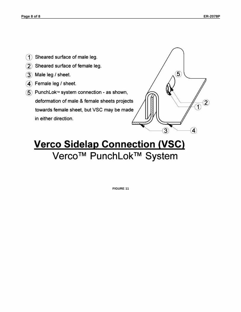
TABLE 1–ALLOWABLE DIAPHRAGM SHEAR VALUES (plf) FOR ARC SPOT OR ARC SEAM WELDSPARALLEL TO DECK FLUTES FOR ALL DECKS EXCEPT VERCOR 1,2,3,4,5
GAGE PROFILEBASE METALTHICKNESS
(in.)
PUDDLE WELD SPACING (in.)
6 9 12 18
22
PLW3 & W3 FORMLOK 0.029 2030 1353 1015 677
B & N 0.0299 2093 1395 1047 698
PLW2 & W2 FORMLOK 0.03 2100 1400 1050 700
21 PLW2, W2 , PLW3, & W3 FORMLOK 0.033 2310 1540 1155 770
20
PLW3 & W3 FORMLOK 0.035 2450 1633 1225 817
B & N 0.0359 2513 1675 1257 838
PLW2 & W2 FORMLOK 0.036 2520 1680 1260 840
19 PLW2, W2 , PLW3, & W3 FORMLOK 0.042 2940 1960 1470 980
18PLW2, W2 , PLW3, & W3 FORMLOK 0.047 3290 2193 1645 1097
B & N 0.0478 3346 2231 1673 1115
16PLW2, W2 , PLW3, & W3 FORMLOK 0.059 4130 2753 2065 1377
B & N 0.0598 4186 2791 2093 13951 "B" - PLB, HSB, PLB & HSB Acoustical, and PLB & B Formlok "N" - PLN, N, PLN & N Acoustical, and PLN & N-Formlok2 See General Note No. 7.a to determine shear values for other weld spacings.3 The minimum arc spot weld effective fusion diameter, de, is 1/2 inch. The minimum arc seam weld effective fusion width, de, is
3/8 inch. The minimum arc seam weld length is 1 inch excluding circular ends. See AWS D 1.3-98 for details.4 Details, workmanship technique and qualification of welds must comply with AWS D 1.3-98.5 Allowable values may not be increased one-third for wind or earthquake loading.
TABLE 2–ALLOWABLE TENSION LOADS (lb) FOR HILTI FASTENERS SUBJECT TO WIND UPLIFT FORCES FOR B AND N DECK 1,2
SUBSTRATETHICKNESS (in.)
HILTI FASTENERDESIGNATION
ALLOWABLE TENSION LOADS (lb)
DECK GAGE & THICKNESS (in.)
22 20 18 160.0299 0.0359 0.0478 0.0598
0.313 to 3/8 X-EDN19-THQ12 382 459 519 519
0.250 to 0.313 X-EDN19-THQ12 382 426 426 426
0.188 to 0.250 X-EDNK22-THQ12 382 459 502 502
1/8 to 0.188 X-EDNK22-THQ12 382 396 396 396
1 "B" - PLB, HSB, PLB & HSB Acoustical, and PLB & B Formlok"N" - PLN, N, PLN & N Acoustical, and PLN & N–Formlok
2 Allowable tension loads are the lesser value of the allowable pullover or pullout loads for the deck gage, fastener, and substratethickness combination.
TABLE 3-ALLOWABLE SHEAR VALUES (lb) FOR PNEUTEK FASTENERSPARALLEL TO DECK FLUTES AND TENSION LOADS (lb) FOR PNEUTEK FASTENERS
SUBJECT TO WIND UPLIFT FORCES FOR B AND N DECK 1,2,3,4
SUBSTRATETHICKNESS (in.)
PNEUTEKFASTENER
DESIGNATION
ALLOWABLE SHEAR VALUES (lb) ALLOWABLE TENSION LOADS (lb)
DECK GAGE & THICKNESS (in.) DECK GAGE & THICKNESS (in.)
22 20 18 16 22 20 18 160.0299 0.0359 0.0478 0.0598 0.0299 0.0359 0.0478 0.0598
0.281 and thicker K66062 or K66075
733 880 1171 1465
411 494 657 818
0.187 to 0.312 K64062 411 494 657 671
0.155 to 0.250 SDK63075 411 470 470 470
0.113 to 0.155 SDK61075 477 573 763 954 373 373 373 373
1 B" - PLB, HSB, PLB & HSB Acoustical, and PLB & B Formlok "N" - PLN, N, PLN & N Acoustical, and PLN & N-Formlok2 Allowable shear strength per SDK61075 fastener for substrate thicknesses between 0.113 and 0.155 may be determined by the
formua: Allowable Shear Value (in lb) = (8500 + 66,000 x t SUBSTR ATE) x t D E C K where thicknesses (t SUBSTR ATE and t D E C K) areexpressed in inches.
3 Allowable shear values may not be increased one-third for wind or earthquake loading.4 Allowable tension loads are the lesser value of the allowable pullover or pullout loads for the deck gage, fastener, and substrate
thickness combination.

Page 3 of 57 Report ER-2078P (12/01/02)
TABLE 4–SECTION PROPERTIES (Per Foot of Width)
DECK TYPE GAGEBASE METALTHICKNESS
(in.)
I, FORDEFLECTION1
(in.4 per foot)
SECTION MODULUS2
(in.3 per foot)
POSITIVE MOMENT NEGATIVE MOMENT
1 5/16" VERCOR3
26 0.0195 0.073 0.099 0.103
24 0.0254 0.098 0.138 0.140
22 0.0314 0.123 0.175 0.174
20 0.0374 0.143 0.207 0.206
PLB, HSB,PLB & B FORMLOK,
PLB & HSBACOUSTICAL4
22 0.0299 0.175 0.187 0.198
20 0.0359 0.216 0.235 0.248
18 0.0478 0.302 0.322 0.335
16 0.0598 0.377 0.411 0.417
PLN, N, and
PLN & N ACOUSTICAL5
22 0.0299 0.655 0.394 0.454
20 0.0359 0.837 0.508 0.562
18 0.0478 1.223 0.731 0.776
16 0.0598 1.647 0.950 1.005
PLN & N FORMLOK4
22 0.0299 0.613 0.361 0.446
20 0.0359 0.780 0.466 0.548
18 0.0478 1.146 0.664 0.737
16 0.0598 1.542 0.851 0.914
PLW2 & W2 FORMLOK4
22 0.030 0.340 0.283 0.287
21 0.033 0.382 0.321 0.328
20 0.036 0.423 0.361 0.370
19 0.042 0.508 0.442 0.453
18 0.047 0.555 0.510 0.511
16 0.059 0.694 0.639 0.639
PLW3 & W3 FORMLOK4
22 0.029 0.718 0.418 0.444
21 0.033 0.837 0.495 0.531
20 0.035 0.896 0.534 0.564
19 0.042 1.075 0.674 0.683
18 0.047 1.203 0.767 0.767
16 0.059 1.509 0.960 0.9601 Value based on average of net I from normal position and
inverted position analysis.2 Values apply to deck in normal position.
3 Values based on a yield strength of 80,000 psi.4 Values based on a yield strength of 38,000 psi.5 Values based on a yield strength of 33,000 psi.
TABLE 5–ALLOWABLE REACTIONS BASED ON WEB CRIPPLING (Pounds Per Foot of Deck Width)1,2,5,6,7
GAGE
B-DECK N-DECK
END REACTION3
INTERIOR REACTION4
END REACTION3
INTERIOR REACTION4
LENGTH OF BEARING LENGTH OF BEARING
2" 3" 4" 3" 4" 2" 3" 4" 4" 5"
22 487 585 683 1250 1498 349 419 489 1104 1287
20 665 784 903 1790 2118 486 572 659 1582 1828
18 1226 1407 1588 3062 3551 916 1051 1186 2695 3066
16 2208 2484 2761 4789 5268 1670 1879 2088 4033 4532
GAGE
W2-FORMLOK W3-FORMLOK
END REACTION3
INTERIOR REACTION4
END REACTION3
INTERIOR REACTION4
LENGTH OF BEARING LENGTH OF BEARING
2" 3" 4" 4" 5" 2" 3" 4" 4" 5"
22 219 263 306 684 797 190 228 267 601 701
21 259 307 356 824 956 240 286 331 781 906
20 301 355 409 972 1123 268 316 365 877 1014
19 396 460 523 1294 1482 374 434 495 1241 1421
18 533 613 693 1587 1807 507 583 659 1528 1740
16 981 1105 1229 2380 2677 942 1062 1181 2309 2597
1 "B"- PLB, HSB, PLB & HSB Acoustical, and PLB & BFormlok; "N" - PLN, N, PLN & N Acoustical, and PLN & N Formlok;“W2" - PLW2 & W2 Formlok; W3" - PLW3 & W3 Formlok
2 Values based on a steel yield point of 38,000 psi.3 Bearing length for reactions at panel end supports.4 Bearing length for reactions at interior supports.5 Values are ASD allowable reactions complying with Section
C3.4 of the A.l.S.l.
6 The allowable values are reactions (or concentrated loads)applied to bare deck and to composite decks during theconstruction phase only, prior to the concrete achievingminimum specified compressive strength.
7 Reactions for cellular deck shall be compared to allowablereactions based on the fluted top section. The allowablereactions for 20 gage W3-FORMLOK may be multiplied by1.05 for W3CD-FORMLOK with a 20 gage fluted top section.

Page 4 of 57 Report ER-2078P (12/01/02)
FIGURE 1–DECK PROFILES
FIGURE 2–ACOUSTICAL DECK
Page 5 of 57 Report ER-2078P (12/01/02)
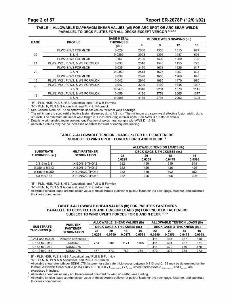
TABLE 6–CELLULAR DECK SECTION PROPERTIES, MOMENT CAPACITIES,AND SHEAR STRENGTHS
5,6,7
DECKTYPE
1GAGE
2 BASE METALTHICKNESS
3
(In.)
Id FOR
DEFLECTIONS
POSITIVEMOMENT
3NEGATIVEMOMENT
3VERTICAL SHEAR
4
SIMPLESPAN(in.
4/ft)
MULTIPLESPAN(in.
4/ft)
+S
(in.3/ft)
+M(in.-kips/ft)
-S(in.
3/ft)
-M(in.-kips /ft)
ENDV (lb/ft)
INTERIORV (lb/ft)
HSB-CD1
BCD-
FORMLOK
20/20 0.0359/0.0359 0.392 0.392 0.284 6.5 0.393 8.9 355 538
20/18 0.0359/0.0478 0.428 0.430 0.292 6.6 0.413 9.4 333 410
20/16 0.0359/0.0598 0.458 0.477 0.298 6.8 0.431 9.8 320 352
18/20 0.0478/0.0359 0.510 0.510 0.430 9.8 0.472 10.7 389 637
18/18 0.0478/0.0478 0.559 0.559 0.441 10.0 0.539 12.3 459 609
18/16 0.0478/0.0598 0.600 0.600 0.450 10.3 0.562 12.8 436 504
16/18 0.0598/0.0478 0.677 0.677 0.610 13.9 0.665 15.1 493 697
16/16 0.0598/0.0598 0.729 0.729 0.622 14.2 0.693 15.8 657 794
N-24CD1
NCD-
FORMLOK
20/20 0.0359/0.0359 1.694 1.694 0.565 12.9 0.801 18.2 606 959
20/18 0.0359/0.0478 1.855 1.912 0.562 12.8 0.985 22.4 564 757
20/16 0.0359/0.0598 1.967 2.159 0.597 13.6 1.027 23.4 540 642
18/20 0.0478/0.0359 2.209 2.209 0.847 19.3 0.969 22.1 664 1155
18/18 0.0478/0.0478 2.421 2.421 0.868 19.8 1.183 26.9 780 1130
18/16 0.0478/0.0598 2.599 2.626 0.885 20.1 1.335 30.4 738 938
16/18 0.0598/0.0478 2.965 2.965 1.194 27.2 1.345 30.6 838 1279
16/16 0.0598/0.0598 3.193 3.193 1.218 27.6 1.606 36.5 1111 1492
W2CD-
FORMLOK
20/20 0.036/0.0359 0.673 0.673 0.406 9.2 0.430 9.9 437 634
20/18 0.036/0.0478 0.722 0.722 0.414 9.4 0.446 10.2 405 493
20/16 0.036/0.0598 0.762 0.762 0.420 9.6 0.460 10.5 385 427
18/20 0.047/0.0359 0.843 0.843 0.571 13.0 0.555 12.6 480 759
18/18 0.047/0.0478 0.906 0.906 0.582 13.3 0.574 13.1 552 717
18/16 0.047/0.0598 0.958 0.958 0.592 13.5 0.592 13.5 518 599
16/18 0.059/0.0478 1.093 1.093 0.744 16.9 0.713 16.2 603 832
16/16 0.059/0.0598 1.158 1.158 0.756 17.2 0.735 16.7 776 938
W3CD-
FORMLOK
20/20 0.036/0.0359 1.460 1.460 0.632 14.4 0.626 14.3 621 923
20/18 0.036/0.0478 1.548 1.548 0.643 14.6 0.651 14.8 579 712
20/16 0.036/0.0598 1.620 1.620 0.689 15.7 0.671 15.3 546 611
18/20 0.047/0.0359 1.793 1.793 0.863 19.6 0.810 18.4 697 1060
18/18 0.047/0.0478 1.920 1.920 0.880 20.0 0.836 19.0 795 1042
18/16 0.047/0.0598 2.027 2.027 0.894 20.4 0.863 19.6 741 1096
16/18 0.059/0.0478 2.310 2.310 1.091 24.8 1.038 23.6 875 1216
16/16 0.059/0.0598 2.440 2.440 1.109 25.2 1.070 24.4 1117 1362
1HSB -CD and N-24 CD are roof decks. BCD, NC D, W 2CD and W 3CD FO RMLO K are composite decks.
2Gage "xx/yy" shall be defined as: First Number (xx) is the gage (or t) of f luted top section. Second Number (yy) is the gage (or thickness) of the flat
bottom section.3
S(+ or -) is the ef fective section modulus. M (+ or -) is the ASD al lowable moment where M=Mn/Sb, with Sb = 1.67.4
Vert ical Shear is the ASD al lowable vertical shear strength based on horizontal shear strength of the resistance welds, where V = Vn/S, with S=2.5
“END" shear strength values are applicable adjacent to supports where deck is not continuous.
"INTERIOR " shear strength values are applicable adjacent to supports where deck is continuous.5
Reactions shall be compared to the allowable reactions due to web crippl ing as shown in Table 5, based on the gage of the fluted top section of the
cellular deck.6
Su perim pos ed loa d an d diap hrag m cap acities sho wn in Tables 8 and 11 -13 for a given con crete type an d thick nes s m ay be app lied to com pos ite
cel lular sections with a f luted top section of the same profile and gage, with or without acoustical perforations in the flat bottom section of the cellular
deck.7
Cellular deck resistance weld locations are i llustrated in Figure 3.
FIGURE 3–CELLULAR DECK RESISTANCE WELD LOCATIONS

Page 6 of 57 Report ER-2078P (12/01/02)
TABLE 7–DIAPHRAGM FLEXIBILITY LIMITATION 1,2,3,4
FLEXIBILITYCATEGORY
F
MAXIMUMSPAN FOR
MASONRY ORCONCRETE
WALLS( in feet)
SPAN-DEPTH LIMITATION
ROTATION NOT CONSIDERED INDIAPHRAGM
ROTATION CONSIDERED INDIAPHRAGM
MASONRY ORCONCRETE WALLS
FLEXIBLEWALLS3
MASONRY ORCONCRETE WALLS
FLEXIBLEWALLS3
Very flexible >150 Not used Not used 2:1 Not used 1½:1
Flexible 70-150 200 2:1 or as required for deflection
3:1 Not used 2:1
Semi-flexible 10-70 400 2½:1 or as required for deflection
4:1 As required for deflection
2½:1
Semi-rigid 1-10 No limitation 3:1 or as required for deflection
5:1 As required for deflection
3:1
Rigid <1 No Limitation As required for deflection
Nolimitation
As required for deflection
3½:1
1 Roof diaphragms are to be investigated regarding their flexibility and recommended span-depth limitations. The limitations shownin Table 7 may be used in lieu of a rational analysis of the anticipated deflections. Refer to diaphragm tables below fordetermination of value of F.
2 Roof diaphragms supporting masonry or concrete walls are to have deflections limited to the following amount:
Where: H = Unsupported height of wall in feet.t = Thickness of wall in inches.E = Modulus of elasticity of wall material for deflection determination in pounds per square inch.
fc = Allowable compressive strength of wall material flexure in pounds per square inch. For concrete, ; for masonry, . 3 When applying these limitations to cantilevered diaphragms, the allowable span-depth ratio will be half that shown.4 The total deflection of the diaphragm, in inches, may be computed from the equation: ) = )f + )w.
Where: )f = Flexural deflection of the diaphragm determined in the same manner as the deflection of beams (see equations below). )w = The web (shear) deflection as defined in the equations below.
DIAPHRAGM DEFLECTIONS (inches)
TYPE OF DIAPHRAGM LOADING CONDIT ION FLEXURAL DEFLECTION )f WEB DEFLECTION )w
Sim ple B eam (at cen ter) Uniform Load
Sim ple B eam (at L I) Uniform Load
Sim ple B eam (at cen ter) Load P appl ied at center
Sim ple B eam (at cen ter)Load P appl ied at 1/3 points of
span
Cantilever Beam (at free end) Uniform Load
Cantilever Beam (at free end) Load P appl ied at free end
Where:E = Modulus of elasticity of steel, 29,5000,000 psi.I = Moment of inertia of flange perimeter members about the
centroidal axis of the diaphragm (in.4).F = Flexibility factor: the average microinches a diaphragm
web will deflect in a span of 1 foot under a shear of 1 lb.L = Span length of simple beam diaphragm (ft)
L1 = Distance between vertical resisting element (such asshear wall) and the point to which the deflection is to bedetermined (ft).
a = Span length of cantilever diaphragm (ft).d = Depth of diaphragm (ft).P = Concentrated load (lb).w = Uniform diaphragm load (lb/ft).qave = Average shear in diaphragm over length L1 (lb/ft).

Page 7 of 57 Report ER-2078P (12/01/02)
TABLE 8–ALLOWABLE SUPERIMPOSED LOADS (psf), DIAPHRAGM SHEAR VALUES, q (plf), AND FLEXIBILITYFACTORS, F, FOR TYPE PLB™-36 & B-36 FORMLOK™ DECK WITH CONCRETE FILL 1,2,3,4,5,6,7
TOTAL SLABDEPTH ANDCONCRETE
TYPE
DECKGAGE
NO. OFDECK
SPANS
SPAN (ft.-in.)
6'-0" 6'-6" 7'-0" 7'-6" 8'-0" 8'-6" 9'-0" 9'-6" 10'-0" 10'-6" 11'-0"
3½"NormalWeight
(145 pcf)
22
1 232 199 173 151 132 117 104 92 82 74 66
2 261 228 202 151 132 117 104 92 82 74 66
3 261 228 202 151 132 117 104 92 82 74 66
q4 1825 1785 1755 1725 1700 1680 1660 1640 1625 1610 1600
F4 0.45 0.46 0.47 0.48 0.48 0.49 0.50 0.50 0.51 0.51 0.52
q7 2035 1980 1935 1895 1855 1825 1800 1775 1750 1730 1715
F7 0.40 0.42 0.43 0.44 0.44 0.45 0.46 0.46 0.47 0.48 0.48
20
1 275 240 183 160 141 124 110 98 88 79 71
2 275 240 212 189 170 124 110 98 88 79 71
3 275 240 212 189 170 124 110 98 88 79 71
q4 1890 1845 1805 1775 1745 1715 1695 1670 1655 1635 1620
F4 0.40 0.41 0.42 0.42 0.43 0.44 0.44 0.45 0.45 0.46 0.46
q7 2145 2080 2020 1975 1930 1895 1860 1830 1805 1780 1760
F7 0.35 0.36 0.37 0.38 0.39 0.40 0.40 0.41 0.42 0.42 0.43
18
1 298 261 230 205 184 137 122 108 97 87 78
2 298 261 230 205 184 167 152 108 97 87 78
3 298 261 230 205 184 167 152 138 127 87 78
q4 2045 1985 1930 1885 1845 1810 1780 1750 1725 1705 1685
F4 0.32 0.33 0.34 0.35 0.35 0.36 0.37 0.37 0.38 0.38 0.39
q7 2380 2295 2220 2155 2095 2050 2005 1965 1930 1895 1865
F7 0.27 0.28 0.29 0.30 0.31 0.32 0.33 0.33 0.34 0.34 0.35
16
1 298 260 230 205 184 166 151 108 96 86 78
2 298 260 230 205 184 166 151 138 127 86 78
3 298 260 230 205 184 166 151 138 127 117 108
q4 2215 2140 2070 2015 1965 1920 1880 1845 1815 1785 1760
F4 0.26 0.27 0.28 0.29 0.30 0.30 0.31 0.32 0.32 0.33 0.33
q7 2635 2525 2430 2350 2280 2215 2160 2110 2065 2025 1990
F7 0.22 0.23 0.24 0.25 0.26 0.26 0.27 0.28 0.28 0.29 0.29
4"NormalWeight
(145 pcf)
22
1 269 231 200 175 153 135 120 107 95 85 76
2 300 266 200 175 153 135 120 107 95 85 76
3 300 266 200 175 153 135 120 107 95 85 76
q4 2065 2025 1995 1965 1940 1915 1900 1880 1865 1850 1835
F4 0.40 0.41 0.41 0.42 0.42 0.43 0.43 0.44 0.44 0.45 0.45
q7 2275 2220 2170 2130 2095 2065 2035 2015 1990 1970 1950
F7 0.36 0.37 0.38 0.39 0.39 0.40 0.40 0.41 0.41 0.42 0.42
20
1 300 244 212 185 163 144 127 113 101 91 81
2 300 279 247 220 163 144 127 113 101 91 81
3 300 279 247 220 163 144 127 113 101 91 81
q4 2130 2085 2045 2010 1980 1955 1930 1910 1890 1875 1860
F4 0.35 0.36 0.37 0.37 0.38 0.38 0.39 0.39 0.40 0.40 0.40
q7 2385 2315 2260 2215 2170 2135 2100 2070 2045 2020 1995
F7 0.32 0.32 0.33 0.34 0.35 0.35 0.36 0.36 0.37 0.37 0.38
See Page 12 for footnotes (continued)

Page 8 of 57 Report ER-2078P (12/01/02)
TABLE 8–ALLOWABLE SUPERIMPOSED LOADS (psf), DIAPHRAGM SHEAR VALUES, q (plf), AND FLEXIBILITYFACTORS, F, FOR TYPE PLB™-36 & B-36 FORMLOK™ DECK WITH CONCRETE FILL 1,2,3,4,5,6,7 – Continued
TOTAL SLABDEPTH ANDCONCRETE
TYPE
DECKGAGE
NO. OFDECK
SPANS
SPAN (ft.-in.)
6'-0" 6'-6" 7'-0" 7'-6" 8'-0" 8'-6" 9'-0" 9'-6" 10'-0" 10'-6" 11'-0"
4"NormalWeight
(145 pcf)
18
1 300 300 266 237 178 157 140 125 112 100 90
2 300 300 266 237 213 193 140 125 112 100 90
3 300 300 266 237 213 193 175 160 112 100 90
q4 2285 2225 2170 2125 2085 2050 2020 1990 1965 1945 1925
F4 0.29 0.29 0.30 0.31 0.31 0.32 0.32 0.33 0.33 0.34 0.34
q7 2620 2530 2460 2395 2335 2285 2240 2205 2165 2135 2105
F7 0.25 0.26 0.27 0.27 0.28 0.28 0.29 0.30 0.30 0.31 0.31
16
1 300 300 265 236 212 192 138 123 110 99 89
2 300 300 265 236 212 192 174 159 110 99 89
3 300 300 265 236 212 192 174 159 146 135 89
q4 2455 2375 2310 2255 2205 2160 2120 2085 2055 2025 2000
F4 0.24 0.25 0.25 0.26 0.26 0.27 0.27 0.28 0.28 0.29 0.29
q7 2870 2765 2670 2590 2520 2455 2400 2350 2305 2265 2230
F7 0.20 0.21 0.22 0.22 0.23 0.24 0.24 0.25 0.25 0.26 0.26
4½"NormalWeight
(145 pcf)
22
1 300 265 229 200 175 155 137 122 109 97 87
2 300 300 229 200 175 155 137 122 109 97 87
3 300 265 229 200 175 155 137 122 109 97 87
q4 2305 2265 2230 2205 2180 2155 2135 2120 2105 2090 2075
F4 0.36 0.36 0.37 0.37 0.38 0.38 0.39 0.39 0.39 0.39 0.40
q7 2510 2460 2410 2370 2335 2305 2275 2250 2230 2210 2190
F7 0.33 0.34 0.34 0.35 0.35 0.36 0.36 0.37 0.37 0.37 0.38
20
1 300 279 242 211 186 164 146 129 116 103 93
2 300 300 282 211 186 164 146 129 116 103 93
3 300 300 282 252 186 164 146 129 116 103 93
q4 2370 2325 2285 2250 2220 2195 2170 2150 2130 2115 2100
F4 0.32 0.32 0.33 0.33 0.34 0.34 0.35 0.35 0.35 0.36 0.36
q7 2620 2555 2500 2450 2410 2370 2340 2310 2280 2260 2235
F7 0.29 0.29 0.30 0.31 0.31 0.32 0.32 0.33 0.33 0.33 0.34
18
1 300 300 300 231 203 180 159 142 127 114 103
2 300 300 300 272 244 220 159 142 127 114 103
3 300 300 300 272 244 220 200 142 127 114 103
q4 2525 2460 2410 2365 2325 2290 2260 2230 2205 2180 2160
F4 0.26 0.26 0.27 0.28 0.28 0.28 0.29 0.29 0.30 0.30 0.30
q7 2860 2770 2695 2630 2575 2525 2480 2440 2405 2375 2345
F7 0.23 0.24 0.24 0.25 0.25 0.26 0.26 0.27 0.27 0.27 0.28
16
1 300 300 300 270 242 177 158 140 126 112 101
2 300 300 300 270 242 219 199 140 126 112 101
3 300 300 300 270 242 219 199 182 167 112 101
q4 2695 2615 2550 2495 2445 2400 2360 2325 2295 2265 2240
F4 0.22 0.22 0.23 0.23 0.24 0.24 0.25 0.25 0.25 0.26 0.26
q7 3110 3000 2910 2830 2760 2695 2640 2590 2545 2505 2470
F7 0.19 0.19 0.20 0.21 0.21 0.22 0.22 0.22 0.23 0.23 0.24
See Page 12 for footnotes (continued)

Page 9 of 57 Report ER-2078P (12/01/02)
TABLE 8–ALLOWABLE SUPERIMPOSED LOADS (psf), DIAPHRAGM SHEAR VALUES, q (plf), AND FLEXIBILITYFACTORS, F, FOR TYPE PLB™-36 & B-36 FORMLOK™ DECK WITH CONCRETE FILL 1,2,3,4,5,6,7 – Continued
TOTAL SLABDEPTH ANDCONCRETE
TYPE
DECKGAGE
NO. OFDECK
SPANS
SPAN (ft.-in.)
6'-0" 6'-6" 7'-0" 7'-6" 8'-0" 8'-6" 9'-0" 9'-6" 10'-0" 10'-6" 11'-0"
5"NormalWeight
(145 pcf)
22
1 300 299 259 226 198 175 155 138 123 109 98
2 300 299 259 226 198 175 155 138 123 109 98
3 300 299 259 226 198 175 155 138 123 109 98
q4 2540 2505 2470 2440 2415 2395 2375 2360 2345 2330 2315
F4 0.32 0.33 0.33 0.34 0.34 0.34 0.35 0.35 0.35 0.35 0.36
q7 2750 2695 2650 2610 2575 2545 2515 2490 2470 2450 2430
F7 0.30 0.31 0.31 0.32 0.32 0.32 0.33 0.33 0.33 0.34 0.34
20
1 300 300 274 239 210 185 164 146 131 117 105
2 300 300 300 239 210 185 164 146 131 117 105
3 300 300 300 239 210 185 164 146 131 117 105
q4 2610 2565 2525 2490 2460 2435 2410 2390 2370 2355 2340
F4 0.29 0.29 0.30 0.30 0.31 0.31 0.31 0.31 0.32 0.32 0.32
q7 2860 2795 2740 2690 2650 2610 2580 2550 2520 2495 2475
F7 0.26 0.27 0.27 0.28 0.28 0.29 0.29 0.30 0.30 0.30 0.30
18
1 300 300 300 260 229 203 180 161 144 129 116
2 300 300 300 300 275 203 180 161 144 129 116
3 300 300 300 300 275 249 180 161 144 129 116
q4 2765 2700 2650 2605 2565 2530 2495 2470 2445 2420 2400
F4 0.24 0.24 0.25 0.25 0.25 0.26 0.26 0.26 0.27 0.27 0.27
q7 3095 3010 2935 2870 2815 2765 2720 2680 2645 2615 2585
F7 0.21 0.22 0.22 0.23 0.23 0.24 0.24 0.24 0.25 0.25 0.25
16
1 300 300 300 300 273 200 178 158 142 127 114
2 300 300 300 300 273 247 225 158 142 127 114
3 300 300 300 300 273 247 225 205 142 127 114
q4 2930 2855 2790 2730 2685 2640 2600 2565 2535 2505 2480
F4 0.20 0.20 0.21 0.21 0.22 0.22 0.22 0.23 0.23 0.23 0.23
q7 3350 3240 3150 3065 2995 2935 2880 2830 2785 2745 2705
F7 0.17 0.18 0.19 0.19 0.19 0.20 0.20 0.21 0.21 0.21 0.22
6"NormalWeight
(145 pcf)
22
1 300 300 300 280 245 216 192 170 152 135 121
2 300 300 300 280 245 216 192 170 152 135 121
3 300 300 300 280 245 216 192 170 152 135 121
q4 3020 2980 2950 2920 2895 2875 2855 2835 2820 2805 2795
F4 0.27 0.28 0.28 0.28 0.28 0.29 0.29 0.29 0.29 0.29 0.29
q7 3230 3175 3130 3080 3055 3020 2995 2970 2945 2925 2910
F7 0.26 0.26 0.26 0.27 0.27 0.27 0.28 0.28 0.28 0.28 0.28
20
1 300 300 300 296 260 229 203 181 162 144 129
2 300 300 300 296 260 229 203 181 162 144 129
3 300 300 300 296 260 229 203 181 162 144 129
q4 3090 3040 3000 2970 2940 2910 2890 2865 2850 2830 2815
F4 0.24 0.25 0.25 0.25 0.26 0.26 0.26 0.26 0.26 0.27 0.27
q7 3340 3275 3220 3170 3125 3090 3055 3025 3000 2975 2955
F7 0.23 0.23 0.23 0.24 0.24 0.24 0.25 0.25 0.25 0.25 0.25
See Page 12 for footnotes (continued)

Page 10 of 57 Report ER-2078P (12/01/02)
TABLE 8–ALLOWABLE SUPERIMPOSED LOADS (psf), DIAPHRAGM SHEAR VALUES, q (plf), AND FLEXIBILITYFACTORS, F, FOR TYPE PLB™-36 & B-36 FORMLOK™ DECK WITH CONCRETE FILL 1,2,3,4,5,6,7 – Continued
TOTAL SLABDEPTH ANDCONCRETE
TYPE
DECKGAGE
NO. OFDECK
SPANS
SPAN (ft.-in.)
6'-0" 6'-6" 7'-0" 7'-6" 8'-0" 8'-6" 9'-0" 9'-6" 10'-0" 10'-6" 11'-0"
6"NormalWeight
(145 pcf)
18
1 300 300 300 300 283 251 223 199 178 159 143
2 300 300 300 300 283 251 223 199 178 159 143
3 300 300 300 300 300 251 223 199 178 159 143
q4 3240 3180 3125 3080 3040 3005 2975 2950 2920 2900 2880
F4 0.20 0.20 0.21 0.21 0.21 0.22 0.22 0.22 0.22 0.22 0.23
q7 3575 3490 3415 3350 3295 3245 3200 3160 3125 3090 3060
F7 0.18 0.19 0.19 0.19 0.20 0.20 0.20 0.21 0.21 0.21 0.21
16
1 300 300 300 300 280 247 220 196 175 157 141
2 300 300 300 300 300 247 220 196 175 157 141
3 300 300 300 300 300 300 278 196 175 157 141
q4 3410 3335 3265 3210 3160 3115 3080 3045 3010 2985 2955
F4 0.17 0.17 0.18 0.18 0.18 0.19 0.19 0.19 0.19 0.20 0.20
q7 3830 3720 3625 3545 3475 3410 3355 3305 3260 3220 3185
F7 0.15 0.16 0.16 0.16 0.17 0.17 0.17 0.18 0.18 0.18 0.18
3½"Structural
LightWeight
(110 pcf)
22
1 261 206 179 157 139 124 110 99 89 — —
2 261 228 202 180 139 124 110 99 89 — —
3 261 228 202 180 139 124 110 99 89 — —
q4 1500 1460 1430 1400 1375 1355 1335 1315 1300 — —
F4 0.55 0.56 0.58 0.59 0.60 0.61 0.62 0.63 0.63 — —
q7 1710 1655 1610 1570 1555 1500 1475 1450 1425 — —
F7 0.48 0.50 0.51 0.53 0.54 0.55 0.56 0.57 0.58 — —
20
1 275 240 212 167 147 131 117 105 94 85 77
2 275 240 212 189 170 154 117 105 94 85 77
3 275 240 212 189 170 154 117 105 94 85 77
q4 1570 1520 1480 1450 1420 1390 1370 1350 1330 1310 1295
F4 0.48 0.49 0.51 0.52 0.53 0.54 0.55 0.56 0.57 0.57 0.58
q7 1820 1755 1700 1650 1605 1570 1535 1505 1480 1455 1435
F7 0.41 0.43 0.44 0.46 0.47 0.48 0.49 0.50 0.51 0.52 0.52
18
1 298 261 230 205 184 167 128 115 104 94 85
2 298 261 230 205 184 167 152 136 116 94 85
3 298 261 230 205 184 167 152 136 116 100 85
q4 1720 1660 1605 1560 1520 1485 1455 1430 1400 1380 1360
F4 0.38 0.39 0.41 0.42 0.43 0.44 0.45 0.46 0.46 0.47 0.48
q7 2055 1970 1895 1830 1775 1725 1680 1640 1605 1570 1540
F7 0.32 0.33 0.34 0.36 0.37 0.38 0.39 0.40 0.41 0.41 0.42
16
1 298 260 230 205 184 166 151 138 127 93 84
2 298 260 230 205 184 166 151 138 127 112 97
3 298 260 230 205 184 166 151 138 127 112 97
q4 1890 1815 1750 1690 1640 1595 1560 1525 1490 1465 1435
F4 0.31 0.32 0.33 0.34 0.35 0.36 0.37 0.38 0.39 0.40 0.41
q7 2310 2200 2105 2025 1955 1890 1835 1785 1745 1700 1665
F7 0.25 0.26 0.28 0.29 0.30 0.31 0.32 0.33 0.33 0.34 0.35
See Page 12 for footnotes (continued)

Page 11 of 57 Report ER-2078P (12/01/02)
TABLE 8–ALLOWABLE SUPERIMPOSED LOADS (psf), DIAPHRAGM SHEAR VALUES, q (plf), AND FLEXIBILITYFACTORS, F, FOR TYPE PLB™-36 & B-36 FORMLOK™ DECK WITH CONCRETE FILL 1,2,3,4,5,6,7 – Continued
TOTAL SLABDEPTH ANDCONCRETE
TYPE
DECKGAGE
NO. OFDECK
SPANS
SPAN (ft.-in.)
6'-0" 6'-6" 7'-0" 7'-6" 8'-0" 8'-6" 9'-0" 9'-6" 10'-0" 10'-6" 11'-0"
4"Structural
LightWeight
(110 pcf)
22
1 277 239 208 183 161 143 128 115 103 93 84
2 300 266 235 209 161 143 128 115 103 93 84
3 300 266 235 183 161 143 128 115 103 93 84
q4 1660 1620 1585 1560 1535 1510 1490 1475 1460 1445 1430
F4 0.50 0.51 0.52 0.53 0.54 0.54 0.55 0.56 0.56 0.57 0.58
q7 1870 1815 1765 1725 1690 1660 1630 1605 1585 1565 1545
F7 0.44 0.45 0.47 0.48 0.49 0.50 0.50 0.51 0.52 0.53 0.53
20
1 300 279 220 193 171 152 135 121 109 99 89
2 300 279 247 220 197 152 135 121 109 99 89
3 300 279 247 220 197 178 135 121 109 99 89
q4 1725 1680 1640 1605 1575 1550 1525 1505 1485 1470 1455
F4 0.44 0.45 0.46 0.47 0.48 0.48 0.49 0.50 0.51 0.51 0.52
q7 1975 1910 1855 1805 1765 1725 1695 1665 1635 1615 1590
F7 0.38 0.39 0.41 0.42 0.43 0.44 0.44 0.45 0.46 0.47 0.47
18
1 300 300 266 237 213 165 148 133 120 108 98
2 300 300 266 237 213 193 175 160 120 108 98
3 300 300 266 237 213 193 175 160 147 108 98
q4 1880 1820 1765 1720 1680 1645 1615 1585 1560 1540 1515
F4 0.35 0.36 0.37 0.38 0.39 0.40 0.40 0.41 0.42 0.42 0.43
q7 2215 2125 2050 1985 1930 1880 1835 1795 1760 1730 1700
F7 0.29 0.31 0.32 0.33 0.34 0.35 0.35 0.36 0.37 0.38 0.38
16
1 300 300 265 236 212 192 174 159 118 107 97
2 300 300 265 236 212 192 174 159 146 135 97
3 300 300 265 236 212 192 174 159 146 135 125
q4 2050 1970 1905 1850 1800 1755 1715 1680 1650 1620 1595
F4 0.28 0.30 0.31 0.32 0.32 0.33 0.34 0.35 0.35 0.36 0.37
q7 2465 2360 2265 2185 2115 2050 1995 1945 1900 1860 1825
F7 0.24 0.25 0.26 0.27 0.28 0.28 0.29 0.30 0.31 0.31 0.32
4¾"Structural
LightWeight
(110 pcf)
22
1 300 292 254 223 197 175 156 140 125 113 102
2 300 300 287 223 197 175 156 140 125 113 102
3 300 300 254 223 197 175 156 140 125 113 102
q4 1895 1855 1825 1795 1770 1750 1730 1710 1695 1680 1670
F4 0.43 0.44 0.45 0.46 0.47 0.47 0.48 0.48 0.49 0.49 0.49
q7 2105 2050 2005 1965 1930 1895 1870 1845 1820 1800 1785
F7 0.39 0.40 0.41 0.42 0.43 0.43 0.44 0.45 0.45 0.46 0.46
20
1 300 300 268 235 208 185 165 148 133 120 109
2 300 300 300 268 208 185 165 148 133 120 109
3 300 300 300 268 241 185 165 148 133 120 109
q4 1965 1915 1875 1840 1810 1785 1760 1740 1725 1705 1690
F4 0.38 0.39 0.40 0.41 0.41 0.42 0.43 0.43 0.44 0.44 0.44
q7 2215 2150 2095 2045 2000 1965 1930 1900 1875 1850 1830
F7 0.34 0.35 0.36 0.37 0.38 0.38 0.39 0.40 0.40 0.41 0.41
See Page 12 for footnotes (continued)

Page 12 of 57 Report ER-2078P (12/01/02)
TABLE 8–ALLOWABLE SUPERIMPOSED LOADS (psf), DIAPHRAGM SHEAR VALUES, q (plf), AND FLEXIBILITYFACTORS, F, FOR TYPE PLB™-36 & B-36 FORMLOK™ DECK WITH CONCRETE FILL 1,2,3,4,5,6,7 – Continued
TOTAL SLABDEPTH ANDCONCRETE
TYPE
DECKGAGE
NO. OFDECK
SPANS
SPAN (ft.-in.)
6'-0" 6'-6" 7'-0" 7'-6" 8'-0" 8'-6" 9'-0" 9'-6" 10'-0" 10'-6" 11'-0"
4¾"Structural
LightWeight
(110 pcf)
18
1 300 300 300 289 226 201 180 161 145 131 119
2 300 300 300 289 260 235 213 161 145 131 119
3 300 300 300 289 260 235 213 195 145 131 119
q4 2115 2055 2000 1955 1915 1880 1850 1825 1795 1775 1755
F4 0.31 0.32 0.33 0.33 0.34 0.35 0.35 0.36 0.36 0.37 0.37
q7 2450 2365 2290 2225 2170 2120 2075 2035 2000 1965 1935
F7 0.27 0.28 0.28 0.29 0.30 0.31 0.31 0.32 0.33 0.33 0.34
16
1 300 300 300 287 258 233 212 159 143 130 117
2 300 300 300 287 258 233 212 194 178 130 117
3 300 300 300 287 258 233 212 194 178 164 152
q4 2285 2210 2145 2085 2035 1990 1955 1920 1885 1860 1830
F4 0.25 0.26 0.27 0.28 0.29 0.29 0.30 0.30 0.31 0.31 0.32
q7 2705 2595 2500 2420 2350 2285 2230 2180 2140 2095 2060
F7 0.22 0.22 0.23 0.24 0.25 0.25 0.26 0.27 0.27 0.28 0.28
5¾"Structural
LightWeight
(110 pcf)
22
1 300 300 300 279 246 219 195 175 157 141 128
2 300 300 300 279 246 219 195 175 157 141 128
3 300 300 300 279 246 219 195 175 157 141 128
q4 2210 2175 2140 2110 2085 2065 2045 2030 2010 2000 1985
F4 0.37 0.38 0.38 0.39 0.39 0.40 0.40 0.41 0.41 0.41 0.41
q7 2420 2365 2320 2280 2245 2210 2185 2160 2140 2115 2100
F7 0.34 0.35 0.36 0.36 0.37 0.37 0.38 0.38 0.39 0.39 0.39
20
1 300 300 300 294 260 231 206 185 166 150 136
2 300 300 300 294 260 231 206 185 166 150 136
3 300 300 300 294 260 231 206 185 166 150 136
q4 2280 2235 2195 2160 2130 2105 2080 2060 2040 2020 2005
F4 0.33 0.34 0.34 0.35 0.35 0.36 0.36 0.37 0.37 0.37 0.37
q7 2530 2465 2410 2360 2320 2280 2250 2215 2190 2165 2145
F7 0.30 0.30 0.31 0.31 0.32 0.32 0.33 0.33 0.34 0.35 0.35
18
1 300 300 300 300 282 251 224 201 182 164 149
2 300 300 300 300 300 251 224 201 182 164 149
3 300 300 300 300 300 293 266 201 182 164 149
q4 2430 2370 2320 2275 2230 2200 2165 2140 2110 2090 2070
F4 0.27 0.27 0.28 0.29 0.29 0.30 0.30 0.30 0.31 0.31 0.31
q7 2765 2680 2605 2540 2485 2435 2390 2350 2315 2280 2255
F7 0.24 0.24 0.25 0.26 0.26 0.27 0.27 0.28 0.28 0.29 0.29
16
1 300 300 300 300 300 248 222 199 179 162 147
2 300 300 300 300 300 291 264 199 179 162 147
3 300 300 300 300 300 291 264 241 222 162 147
q4 2600 2525 2460 2400 2350 2310 2270 2235 2200 2175 2150
F4 0.22 0.23 0.24 0.24 0.25 0.25 0.26 0.26 0.26 0.27 0.27
q7 3020 2910 2815 2735 2665 2605 2550 2500 2455 2415 2375
F7 0.19 0.20 0.21 0.21 0.22 0.22 0.23 0.23 0.24 0.24 0.25
1 Shoring calculations based on deck supporting dead load of concrete plus either 20 psf uniform construction live load or 150 lbconcentrated live load for flexure. Dead load deflection limited to L/180 of span length, but not to exceed ¾ inch.
2 Shoring is required at midspan for superimposed load values in the shaded area to the right of the heavy line.3 Steel for deck to have a minimum yield strength of 38,000 psi.4 Total slab depth is nominal depth from top of concrete to bottom of steel deck.5 Concrete fill to have a minimum compressive strength fNc = 3000 psi.6 The number after the letter q or F indicates the number of puddle welds per panel and at interior supports.7 Support reactions for unshored spans due to dead loads and uniform construction live loads shall not exceed values set forth in
Table 5.

Page 13 of 57 Report ER-2078P (12/01/02)
TABLE 9–ALLOWABLE SUPERIMPOSED LOADS (psf) FOR TYPE BR-24, BR-30, AND BR-36 FORMLOK™ DECK WITH CONCRETE FILL 1,2,3,4,5,6
TOTAL SLABDEPTH ANDCONCRETE
TYPEDECKGAGE
SPAN (ft-in.)
6’-0” 6’-6” 7’-0” 7’-6” 8’-0” 8’-6” 9’-0” 9’-6” 10’-0” 10’-6” 11’-0” 11'-6" 12'-0"
4"NormalWeight
(145 pcf)
22 290 268 221 204 189 177 165 155
20 288 266 247 230 187 175 164 154 145
18 286 264 245 229 214 202 191 152 143 135 127 120 114
16 285 263 244 228 214 201 190 180 171 133 126 119 113
4½”NormalWeight
(145 pcf)
22 330 272 250 232 215 200 188 176 166
20 328 303 281 230 213 199 186 174 164 155
18 324 300 278 260 243 229 183 172 162 153 144 136 129
16 323 298 277 258 242 228 215 204 160 151 142 135 128
5"NormalWeight
(145 pcf)
22 371 306 282 260 242 225 211
20 369 340 279 258 240 223 209 196 184
18 364 336 312 291 273 220 205 193 181 170 161 153 145
16 362 334 310 290 271 255 241 190 179 169 159 151 143
4"Structural
Light Weight(110 pcf)
22 213 197 183 149 138 129 120
20 212 196 182 170 159 128 120 112 105
18 210 194 180 168 157 148 140 132 104 98 93 87 83
16 210 194 180 168 157 148 140 132 125 119 92 87 82
4½”Structural
Light Weight(110 pcf)
22 242 224 183 169 157 146
20 240 222 206 192 155 145 135 127
18 238 220 203 190 178 167 158 125 117 111 104
16 236 218 203 189 178 167 158 150 142 135 103 98 93
4¾”Structural
Light Weight(110 pcf)
22 257 237 194 180 166 154 145
20 255 236 219 204 165 153 143 134
18 252 233 216 202 189 178 168 132 124 117 110
16 251 231 215 200 188 177 167 158 150 116 109 103 98
5"Structural
Light Weight(110 pcf)
22 272 251 205 189 176 163 153
20 270 249 231 216 174 162 151 142 134
18 267 246 228 213 200 188 178 140 131 123 117 110 105
16 265 244 227 212 199 187 177 167 159 122 115 109 103
1 One row of shoring is required for spans in the shaded area to the right of the heavy line, based on three continuous span conditions.2
Reinforcement in slab for temperature change and shrinkage control shall be not less than 6 x 6-W1.4 x W1.4 W.W.F.3
Total slab depth is nominal depth from top of concrete to bottom of steel deck.4 f'c = 3000 psi5 Embossments are not required in either flange for Type BR decks6 Shoring calculations based on deck supporting dead load of concrete plus either 20 psf uniform construction live load or 150 lb
concentrated live load for flexure. Dead load deflection limited to L/180 of span length, but not to exceed ¾ inch.

Page 14 of 57 Report ER-2078P (12/01/02)
TABLE 10–ALLOWABLE DIAPHRAGM SHEAR VALUES, q (plf), FOR BR-36 AND BR-36 FORMLOK™ DECKS WITH CONCRETE FILL 1, 2
TOTAL SLABDEPTH ANDCONCRETE
TYPEDECKGAGE
WELDSPER
SHEET TOSUPPORT
SPAN (ft-in.)
5'-0" 6'-0" 7'-0" 8'-0" 9'-0" 10'-0"
3½”NormalWeight
(145 pcf)
22q4 1835 1755 1695 1655 1620 1595
q6 2000 1890 1815 1760 1715 1675
20q4 1895 1800 1730 1680 1640 1610
q6 2090 1965 1870 1805 1750 1705
18q4 2035 1910 1815 1750 1695 1655
q6 2300 2130 2005 1915 1845 1785
16q4 2195 2035 1920 1835 1770 1715
q6 2525 2310 2155 2040 1950 1880
4"NormalWeight
(145 pcf)
22 q4 2070 1995 1935 1895 1860 1835
q6 2235 2130 2055 1995 1950 1915
20 q4 2135 2040 1970 1920 1880 1845
q6 2330 2205 2110 2040 1990 1945
18 q4 2275 2145 2055 1990 1935 1895
q6 2540 2365 2245 2153 2080 2025
16 q4 2430 2275 2160 2075 2010 1955
q6 2760 2550 2395 2280 2190 2120
5"NormalWeight
(145 pcf)
22 q4 2550 2470 2415 2370 2340 2312
q6 2715 2610 2530 2475 2430 2395
20 q4 2610 2515 2450 2395 2355 2325
q6 2810 2680 2590 2520 2465 2425
18 q4 2750 2625 2535 2465 2415 2370
q6 3015 2845 2725 2630 2560 2505
16 q4 2910 2750 2640 2550 2485 2435
q6 3240 3025 2875 2760 2670 2600
6"NormalWeight
(145 pcf)
22 q4 3030 2950 2895 2850 2815 2790
q6 3195 3085 3010 2955 2910 2875
20 q4 3090 2995 2925 2875 2835 2805
q6 3290 3160 3065 3000 2945 2900
18 q4 3230 3105 3015 2945 2890 2850
q6 3495 3325 3200 3110 3040 2980
16 q4 3390 3230 3115 3030 2965 2910
q6 3720 3505 3350 3235 3150 3075
See Page 15 for footnotes. (continued)

Page 15 of 57 Report ER-2078P (12/01/02)
TABLE 10–ALLOWABLE DIAPHRAGM SHEAR VALUES, q (plf), FOR BR-36 and BR-36 FORMLOK™DECKS WITH CONCRETE FILL 1, 2 – Continued
TOTAL SLABDEPTH ANDCONCRETE
TYPEDECKGAGE
WELDSPER
SHEET TOSUPPORT
SPAN (ft-in.)
5'-0" 6'-0" 7'-0" 8'-0" 9'-0" 10'-0"
3½”Structural
Light Weight(110 pcf)
22q4 1510 1430 1373 1330 1295 1270
q6 1675 1565 1490 1435 1390 1355
20q4 1570 1475 1405 1355 1315 1285
q6 1770 1640 1550 1480 1425 1380
18q4 1710 1585 1495 1425 1370 1330
q6 1975 1805 1680 1590 1520 1460
16q4 1870 1710 1595 1510 1445 1390
q6 2200 1985 1830 1715 1630 1555
4"Structural
Light Weight(110 pcf)
22 q4 1665 1585 1530 1490 1455 1430
q6 1830 1725 1650 1590 1545 1510
20 q4 1730 1630 1565 1515 1475 1440
q6 1925 1795 1705 1635 1585 1540
18 q4 1870 1740 1650 1585 1530 1485
q6 2130 1960 1840 1750 1675 1620
16 q4 2025 1865 1755 1670 1600 1550
q6 2355 2140 1990 1875 1785 1715
4¾”Structural
Light Weight(110 pcf)
22q4 1905 1825 1770 1725 1690 1665
q6 2070 1960 1885 1830 1785 1750
20q4 1965 1870 1800 1750 1710 1680
q6 2165 2035 1940 1875 1820 1775
18q4 2105 1980 1890 1820 1765 1725
q6 2370 2200 2075 1985 1915 1855
16q4 2265 2105 1990 1905 1840 1785
q6 2595 2400 2225 2110 2025 1950
5¾”Structural
Light Weight(110 pcf)
22q4 2220 2140 2085 2040 2010 1980
q6 2385 2280 2200 2145 2100 2065
20q4 2280 2185 2115 2065 2025 1995
q6 2480 2350 2260 2190 2135 2095
18q4 2420 2295 2205 2135 2085 2040
q6 2685 2515 2390 2300 2230 2170
16q4 2580 2420 2305 2220 2155 2100
q6 2910 2695 2545 2430 2340 2265
1 Total slab depth, in inches, from bottom of deck to top of concrete.
2 Concrete fill to have a minimum compressive strength fNc = 3000 psi.

Page 16 of 57 Report ER-2078P (12/01/02)
TABLE 11–ALLOWABLE SUPERIMPOSED LOADS (psf), DIAPHRAGM SHEAR VALUES, q (plf), AND FLEXIBILITYFACTORS, F, FOR TYPE PLW2™-36 & W2-36 FORMLOK™ DECK WITH CONCRETE FILL 1,2,3,4,5,6,7,8
TOTAL SLABDEPTH ANDCONCRETE
TYPE
DECKGAGE
NO. OFDECK
SPANS
SPAN (ft.-in.)
7'-0" 7'-6" 8'-0" 8'-6" 9'-0" 9'-6" 10'-0" 10'-6" 11'-0" 11'-6" 12'-0"
4"NormalWeight
(145 pcf)
22
1 255 190 167 148 131 116 104 93 83 75 67
2 255 227 204 148 131 116 104 93 83 75 67
3 255 227 204 185 131 116 104 93 83 75 67
q3 1665 1650 1635 1620 1610 1595 1590 1580 1570 1565 1555
q4 1780 1750 1720 1700 1680 1660 1640 1620 1610 1600 1590
21
1 286 255 192 170 151 135 121 108 97 88 79
2 286 255 229 207 151 135 121 108 97 88 79
3 286 255 229 207 188 135 121 108 97 88 79
q3 1670 1655 1635 1620 1610 1595 1585 1575 1565 1560 1550
q4 1810 1770 1740 1720 1700 1680 1660 1640 1620 1610 1600
20
1 317 282 252 192 171 153 138 124 112 101 92
2 317 282 254 229 208 153 138 124 112 101 92
3 317 282 254 229 208 187 166 124 112 101 92
q3 1680 1660 1640 1625 1610 1595 1585 1575 1565 1555 1550
q4 1840 1800 1770 1740 1720 1690 1670 1650 1640 1620 1610
19
1 380 339 305 259 214 191 173 156 142 129 118
2 380 339 305 275 249 220 195 156 142 129 118
3 380 339 305 275 249 220 195 174 152 129 118
q3 1700 1680 1655 1635 1620 1605 1590 1580 1570 1560 1550
q4 1900 1860 1820 1790 1760 1730 1710 1690 1670 1650 1640
18
1 400 388 348 303 253 211 203 184 167 147 129
2 400 388 348 315 278 246 218 193 167 147 129
3 400 388 348 315 278 246 218 193 168 147 129
q3 1725 1700 1675 1655 1635 1615 1600 1590 1575 1565 1555
q4 1960 1910 1870 1830 1800 1770 1750 1720 1700 1680 1660
1 400 388 348 315 277 245 217 194 166 152 139
2 400 388 348 315 277 245 217 194 173 155 140
16 3 400 388 348 315 277 245 217 194 173 155 140
q3 1790 1760 1730 1700 1675 1655 1635 1620 1605 1590 1575
q4 2110 2050 1990 1950 1910 1870 1840 1810 1780 1760 1740
4½”NormalWeight
(145 pcf)
22
1 246 214 188 166 147 131 117 104 93 84 75
2 288 257 188 166 147 131 117 104 93 84 75
3 288 257 231 166 147 131 117 104 93 84 75
q3 1905 1890 1875 1860 1845 1835 1825 1820 1810 1805 1795
q4 2020 1990 1960 1940 1920 1900 1880 1860 1850 1840 1830
21
1 322 245 216 191 170 151 135 122 109 98 89
2 322 287 258 191 170 151 135 122 109 98 89
3 322 287 258 233 170 151 135 122 109 98 89
q3 1910 1890 1875 1860 1845 1835 1825 1815 1805 1800 1790
q4 2040 2010 1980 1950 1930 1910 1900 1880 1860 1850 1840
20
1 357 318 243 216 192 172 154 139 126 114 103
2 357 318 286 258 192 172 154 139 126 114 103
3 357 318 286 258 235 215 154 139 126 114 103
q3 1920 1900 1880 1865 1850 1835 1825 1815 1805 1795 1790
q4 2070 2040 2010 1980 1950 1930 1910 1890 1880 1860 1850
See Page 21 for footnotes. (continued)

Page 17 of 57 Report ER-2078P (12/01/02)
TABLE 11–ALLOWABLE SUPERIMPOSED LOADS (psf), DIAPHRAGM SHEAR VALUES, q (plf), AND FLEXIBILITYFACTORS, F, FOR TYPE PLW2™-36 & W2-36 FORMLOK™ DECK WITH CONCRETE FILL 1, 2, 3, 4, 5, 6, 7, 8 – Continued
TOTAL SLABDEPTH ANDCONCRETE
TYPE
DECKGAGE
NO. OFDECK
SPANS
SPAN (ft.-in.)
7'-0" 7'-6" 8'-0" 8'-6" 9'-0" 9'-6" 10'-0" 10'-6" 11'-0" 11'-6" 12'-0"
4½"NormalWeight
(145 pcf)
19
1 400 382 343 289 239 214 193 175 159 144 131
2 400 382 343 310 282 257 193 175 159 144 131
3 400 382 343 310 282 257 231 198 159 144 131
q3 1940 1915 1895 1875 1860 1845 1830 1820 1810 1795 1790
q4 2140 2100 2060 2030 2000 1970 1950 1930 1910 1890 1880
18
1 400 400 391 342 282 251 227 206 187 171 156
2 400 400 391 354 322 293 260 206 187 171 156
3 400 400 391 354 322 293 260 232 201 172 156
q3 1965 1935 1915 1890 1875 1855 1840 1825 1815 1805 1795
q4 2200 2150 2110 2070 2040 2010 1990 1960 1940 1920 1900
16
1 400 400 390 352 320 293 269 204 185 169 155
2 400 400 390 352 320 293 269 248 229 213 155
3 400 400 390 352 320 293 269 248 229 213 198
q3 2030 1995 1965 1940 1915 1895 1875 1860 1845 1830 1815
q4 2350 2290 2240 2190 2150 2110 2080 2050 2020 2000 1980
5"NormalWeight
(145 pcf)
22
1 275 240 211 186 165 146 130 117 104 93 84
2 323 288 211 186 165 146 130 117 104 93 84
3 323 288 211 186 165 146 130 117 104 93 84
q3 2145 2125 2110 2100 2085 2075 2065 2055 2050 2040 2035
q4 2250 2220 2190 2170 2150 2130 2120 2100 2090 2070 2060
21
1 313 274 241 213 190 169 151 136 122 110 99
2 361 322 289 213 190 169 151 136 122 110 99
3 361 322 289 261 190 169 151 136 122 110 99
q3 2150 2130 2115 2100 2085 2075 2065 2055 2045 2035 2030
q4 2280 2250 2220 2190 2170 2150 2130 2110 2100 2080 2070
20
1 400 308 272 241 215 192 173 155 140 127 115
2 400 356 320 241 215 192 173 155 140 127 115
3 400 356 320 289 263 192 173 155 140 127 115
q3 2160 2135 2120 2105 2090 2075 2065 2055 2045 2035 2025
q4 2310 2270 2240 2210 2190 2170 2150 2130 2110 2090 2080
19
1 400 400 383 298 267 240 216 195 177 161 147
2 400 400 383 347 315 240 216 195 177 161 147
3 400 400 383 347 315 288 257 195 177 161 147
q3 2180 2155 2135 2115 2100 2085 2070 2060 2045 2035 2025
q4 2370 2330 2290 2260 2230 2200 2180 2160 2140 2120 2110
18
1 400 400 400 375 304 280 253 229 209 190 174
2 400 400 400 395 359 328 301 229 209 190 174
3 400 400 400 395 359 328 301 258 220 190 174
q3 2205 2175 2150 2130 2110 2095 2080 2065 2055 2040 2030
q4 2430 2380 2340 2300 2270 2240 2220 2190 2170 2150 2140
16
1 400 400 400 393 357 326 250 227 206 188 172
2 400 400 400 393 357 326 300 276 256 188 172
3 400 400 400 393 357 326 300 276 256 237 172
q3 2270 2235 2205 2180 2155 2135 2115 2100 2080 2070 2055
q4 2570 2510 2460 2420 2380 2340 2310 2280 2250 2230 2210
See Page 21 for footnotes. (continued)

Page 18 of 57 Report ER-2078P (12/01/02)
TABLE 11–ALLOWABLE SUPERIMPOSED LOADS (psf), DIAPHRAGM SHEAR VALUES, q (plf), AND FLEXIBILITYFACTORS, F, FOR TYPE PLW2™-36 & W2-36 FORMLOK™ DECK WITH CONCRETE FILL 1, 2, 3, 4, 5, 6, 7, 8 – Continued
TOTAL SLABDEPTH ANDCONCRETE
TYPE
DECKGAGE
NO. OFDECK
SPANS
SPAN (ft.-in.)
7'-0" 7'-6" 8'-0" 8'-6" 9'-0" 9'-6" 10'-0" 10'-6" 11'-0" 11'-6" 12'-0"
5½”NormalWeight
(145 pcf)
22
1 306 267 234 207 183 163 145 130 116 104 93
2 359 267 234 207 183 163 145 130 116 104 93
3 359 320 234 207 183 163 145 130 116 104 93
q3 2385 2365 2350 2335 2325 2315 2305 2295 2290 2280 2275
q4 2490 2460 2440 2410 2390 2370 2360 2340 2330 2320 2310
21
1 348 304 268 237 211 188 168 151 136 122 110
2 400 358 268 237 211 188 168 151 136 122 110
3 400 358 321 237 211 188 168 151 136 122 110
q3 2390 2370 2355 2340 2325 2315 2300 2295 2285 2275 2270
q4 2520 2490 2460 2430 2410 2390 2370 2350 2340 2330 2320
20
1 400 343 302 268 239 214 192 173 156 141 127
2 400 396 356 268 239 214 192 173 156 141 127
3 400 396 356 321 239 214 192 173 156 141 127
q3 2395 2375 2360 2340 2325 2315 2305 2290 2285 2275 2265
q4 2550 2510 2480 2450 2430 2410 2390 2370 2360 2340 2330
19
1 400 400 400 331 296 266 240 217 197 179 163
2 400 400 400 385 350 266 240 217 197 179 163
3 400 400 400 385 350 320 240 217 197 179 163
q3 2420 2395 2375 2355 2340 2325 2310 2295 2285 2275 2265
q4 2620 2580 2540 2510 2480 2450 2430 2410 2390 2370 2350
18
1 400 400 400 400 345 311 281 255 232 211 193
2 400 400 400 400 399 365 281 255 232 211 193
3 400 400 400 400 399 365 330 279 232 211 193
q3 2445 2415 2390 2370 2350 2335 2320 2305 2295 2280 2270
q4 2680 2630 2590 2550 2520 2490 2460 2440 2420 2400 2380
16
1 400 400 400 400 396 362 277 252 229 208 190
2 400 400 400 400 396 362 332 306 229 208 190
3 400 400 400 400 396 362 332 306 283 263 190
q3 2510 2475 2445 2420 2395 2375 2355 2335 2320 2305 2295
q4 2820 2760 2710 2670 2630 2590 2560 2530 2500 2470 2450
6½”NormalWeight
(145 pcf)
22
1 370 323 283 250 221 197 175 157 140 126 113
2 370 323 283 250 221 197 175 157 140 126 113
3 400 323 283 250 221 197 175 157 140 126 113
q3 2860 2845 2830 2815 2805 2795 2785 2775 2765 2760 2750
q4 2970 2940 2920 2890 2870 2850 2840 2820 2810 2790 2780
21
1 400 368 324 286 255 227 203 182 164 148 133
2 400 368 324 286 255 227 203 182 164 148 133
3 400 400 324 286 255 227 203 182 164 148 133
q3 2865 2850 2830 2815 2805 2790 2780 2770 2760 2755 2745
q4 3000 2970 2940 2910 2890 2870 2850 2830 2820 2800 2790
20
1 400 400 365 324 288 258 232 208 188 170 154
2 400 400 365 324 288 258 232 208 188 170 154
3 400 400 400 324 288 258 232 208 188 170 154
q3 2875 2855 2835 2820 2805 2790 2780 2770 2760 2750 2745
q4 3030 2990 2960 2930 2910 2890 2870 2850 2830 2820 2810
See Page 21 for footnotes. (continued)

Page 19 of 57 Report ER-2078P (12/01/02)
TABLE 11–ALLOWABLE SUPERIMPOSED LOADS (psf), DIAPHRAGM SHEAR VALUES, q (plf), AND FLEXIBILITYFACTORS, F, FOR TYPE PLW2™-36 & W2-36 FORMLOK™ DECK WITH CONCRETE FILL 1, 2, 3, 4, 5, 6, 7, 8 – Continued
TOTAL SLABDEPTH ANDCONCRETE
TYPE
DECKGAGE
NO. OFDECK
SPANS
SPAN (ft.-in.)
7'-0" 7'-6" 8'-0" 8'-6" 9'-0" 9'-6" 10'-0" 10'-6" 11'-0" 11'-6" 12'-0"
6½”NormalWeight
(145 pcf)
19
1 400 400 400 400 357 321 289 262 237 216 197
2 400 400 400 400 357 321 289 262 237 216 197
3 400 400 400 400 400 321 289 262 237 216 197
q3 2900 2875 2850 2835 2815 2800 2785 2775 2765 2755 2745
q4 3100 3060 3020 2990 2960 2930 2910 2890 2870 2850 2830
18
1 400 400 400 400 400 375 339 307 279 255 233
2 400 400 400 400 400 375 339 307 279 255 233
3 400 400 400 400 400 400 374 307 279 255 233
q3 2920 2895 2870 2850 2830 2810 2795 2785 2770 2760 2750
q4 3150 3110 3070 3030 3000 2970 2940 2920 2900 2880 2860
16
1 400 400 400 400 400 370 334 303 276 251 230
2 400 400 400 400 400 400 400 303 276 251 230
3 400 400 400 400 400 400 400 369 341 251 230
q3 2990 2955 2925 2895 2875 2850 2835 2815 2800 2785 2770
q4 3300 3240 3190 3150 3110 3070 3040 3010 2980 2950 2930
4"Structural
LightWeight
(110 pcf)
22
1 255 227 176 156 140 125 113 102 92 83 76
2 255 227 204 185 140 125 113 102 92 83 76
3 255 227 204 185 168 125 113 102 92 83 76
q3 1340 1325 1310 1295 1285 1275 1265 1255 1245 1240 1230
q4 1450 1420 1400 1370 1350 1330 1320 1300 1290 1280 1270
21
1 286 255 229 178 160 143 129 117 106 97 87
2 286 255 229 207 188 172 129 117 106 97 87
3 286 255 229 207 188 172 151 117 106 97 87
q3 1345 1330 1310 1295 1285 1270 1260 1250 1240 1235 1225
q4 1480 1450 1420 1390 1370 1350 1330 1310 1300 1280 1270
20
1 317 282 254 229 180 162 146 133 117 103 90
2 317 282 254 229 208 182 156 133 117 103 90
3 317 282 254 229 208 182 156 135 117 103 90
q3 1355 1335 1315 1300 1285 1275 1260 1250 1240 1230 1225
q4 1510 1470 1440 1410 1390 1370 1350 1330 1310 1300 1290
19
1 380 339 305 272 229 195 167 144 125 110 97
2 380 339 305 272 229 195 167 144 125 110 97
3 380 339 305 272 229 195 167 144 125 110 97
q3 1380 1355 1330 1315 1295 1280 1265 1255 1245 1235 1225
q4 1580 1540 1500 1470 1440 1410 1390 1370 1350 1330 1310
18
1 400 388 343 286 241 205 175 152 132 115 102
2 400 388 343 286 241 205 175 152 132 115 102
3 400 388 343 286 241 205 175 152 132 115 102
q3 1400 1375 1350 1330 1310 1295 1275 1265 1250 1240 1230
q4 1630 1590 1550 1510 1480 1450 1420 1400 1380 1360 1340
16
1 400 388 348 308 267 227 195 168 146 128 113
2 400 388 348 308 267 227 195 168 146 128 113
3 400 388 348 308 267 227 195 168 146 128 113
q3 1470 1435 1405 1375 1355 1330 1315 1295 1280 1265 1250
q4 1780 1720 1670 1630 1590 1550 1520 1490 1460 1430 1410
See Page 21 for footnotes. (continued)

Page 20 of 57 Report ER-2078P (12/01/02)
TABLE 11–ALLOWABLE SUPERIMPOSED LOADS (psf), DIAPHRAGM SHEAR VALUES, q (plf), AND FLEXIBILITYFACTORS, F, FOR TYPE PLW2™-36 & W2-36 FORMLOK™ DECK WITH CONCRETE FILL 1, 2, 3, 4, 5, 6, 7, 8 – Continued
TOTAL SLABDEPTH ANDCONCRETE
TYPE
DECKGAGE
NO. OFDECK
SPANS
SPAN (ft.-in.)
7'-0" 7'-6" 8'-0" 8'-6" 9'-0" 9'-6" 10'-0" 10'-6" 11'-0" 11'-6" 12'-0"
4½”Structural
LightWeight
(110 pcf)
22
1 288 225 198 176 157 141 127 114 103 94 85
2 288 257 231 208 157 141 127 114 103 94 85
3 288 257 231 208 190 141 127 114 103 94 85
q3 1500 1480 1465 1455 1440 1430 1420 1410 1405 1395 1390
q4 1610 1580 1550 1530 1510 1490 1480 1460 1450 1430 1420
21
1 322 287 226 201 180 161 146 132 119 109 99
2 322 287 258 233 212 161 146 132 119 109 99
3 322 287 258 233 212 194 146 132 119 109 99
q3 1505 1485 1470 1455 1440 1430 1420 1410 1400 1390 1385
q4 1640 1610 1580 1550 1530 1510 1490 1470 1460 1440 1430
20
1 357 318 286 258 202 182 165 149 136 124 113
2 357 318 286 258 235 215 165 149 136 124 113
3 357 318 286 258 235 215 197 180 136 124 113
q3 1515 1495 1475 1460 1445 1430 1420 1410 1400 1390 1380
q4 1670 1630 1600 1570 1550 1530 1510 1490 1470 1450 1440
19
1 400 382 343 310 282 236 204 185 169 152 134
2 400 382 343 310 282 257 231 200 169 152 134
3 400 382 343 310 282 257 231 200 174 152 134
q3 1535 1510 1490 1470 1455 1440 1425 1415 1400 1390 1385
q4 1730 1690 1650 1620 1590 1560 1540 1520 1500 1480 1470
18
1 400 400 391 354 322 279 235 210 182 160 141
2 400 400 391 354 322 283 243 210 182 160 141
3 400 400 391 354 322 283 243 210 182 160 141
q3 1560 1530 1510 1485 1465 1450 1435 1420 1410 1400 1385
q4 1790 1740 1700 1660 1630 1600 1580 1560 1540 1520 1500
16
1 400 400 390 352 320 293 269 232 202 177 156
2 400 400 390 352 320 293 269 232 202 177 156
3 400 400 390 352 320 293 269 232 202 177 156
q3 1625 1590 1560 1535 1510 1490 1470 1455 1440 1425 1410
q4 1940 1880 1830 1780 1740 1700 1670 1640 1620 1590 1570
5¼”Structural
LightWeight
(110 pcf)
22
1 303 266 235 208 186 167 150 135 122 111 100
2 341 304 273 208 186 167 150 135 122 111 100
3 341 304 273 247 186 167 150 135 122 111 100
q3 1735 1720 1705 1690 1680 1670 1660 1650 1640 1635 1625
q4 1850 1820 1790 1770 1750 1730 1710 1690 1680 1670 1660
21
1 381 340 267 237 212 191 172 155 141 128 117
2 381 340 305 276 212 191 172 155 141 128 117
3 381 340 305 276 251 191 172 155 141 128 117
q3 1740 1725 1705 1690 1680 1665 1655 1645 1635 1630 1620
q4 1880 1840 1810 1790 1770 1750 1730 1710 1700 1680 1670
20
1 400 376 338 267 239 215 194 176 160 146 133
2 400 376 338 305 278 215 194 176 160 146 133
3 400 376 338 305 278 254 233 176 160 146 133
q3 1750 1730 1710 1695 1680 1670 1655 1645 1635 1625 1620
q4 1910 1870 1840 1810 1790 1760 1740 1720 1710 1690 1680
See Page 21 for footnotes. (continued)

Page 21 of 57 Report ER-2078P (12/01/02)
TABLE 11–ALLOWABLE SUPERIMPOSED LOADS (psf), DIAPHRAGM SHEAR VALUES, q (plf), AND FLEXIBILITYFACTORS, F, FOR TYPE PLW2™-36 & W2-36 FORMLOK™ DECK WITH CONCRETE FILL 1, 2, 3, 4, 5, 6, 7, 8 – Continued
TOTAL SLABDEPTH ANDCONCRETE
TYPE
DECKGAGE
NO. OFDECK
SPANS
SPAN (ft.-in.)
7'-0" 7'-6" 8'-0" 8'-6" 9'-0" 9'-6" 10'-0" 10'-6" 11'-0" 11'-6" 12'-0"
5¼”Structural
LightWeight
(110 pcf)
19
1 400 400 400 366 324 265 240 218 199 182 167
2 400 400 400 366 332 304 279 218 199 182 167
3 400 400 400 366 332 304 279 257 231 182 167
q3 1775 1750 1725 1710 1690 1675 1660 1650 1640 1630 1620
q4 1970 1930 1890 1860 1830 1800 1780 1760 1740 1720 1710
18
1 400 400 400 400 379 320 279 254 232 213 195
2 400 400 400 400 379 346 318 293 232 213 195
3 400 400 400 400 379 346 318 293 264 236 195
q3 1795 1770 1745 1725 1705 1690 1670 1660 1645 1635 1625
q4 2030 1980 1940 1900 1870 1840 1820 1790 1770 1750 1730
16
1 400 400 400 400 376 344 316 291 230 210 193
2 400 400 400 400 376 344 316 291 269 250 233
3 400 400 400 400 376 344 316 291 269 250 233
q3 1865 1830 1800 1770 1750 1725 1710 1690 1675 1660 1645
q4 2180 2120 2070 2020 1980 1940 1910 1880 1850 1830 1810
6¼”Structural
LightWeight
(110 pcf)
22
1 368 323 285 254 226 203 182 164 149 135 122
2 400 370 285 254 226 203 182 164 149 135 122
3 400 370 332 254 226 203 182 164 149 135 122
q3 2055 2035 2020 2005 1995 1985 1975 1965 1955 1950 1945
q4 2160 2130 2110 2080 2060 2040 2030 2010 2000 1990 1980
21
1 400 366 324 289 258 232 209 189 171 156 142
2 400 400 371 289 258 232 209 189 171 156 142
3 400 400 371 335 258 232 209 189 171 156 142
q3 2060 2040 2020 2005 1995 1980 1970 1960 1955 1945 1940
q4 2190 2160 2130 2100 2080 2060 2040 2020 2010 1990 1980
20
1 400 400 364 324 291 261 236 214 195 177 162
2 400 400 400 371 291 261 236 214 195 177 162
3 400 400 400 371 337 261 236 214 195 177 162
q3 2065 2045 2025 2010 1995 1985 1970 1960 1950 1945 1935
q4 2220 2180 2150 2120 2100 2080 2060 2040 2020 2010 2000
19
1 400 400 400 397 357 322 292 265 242 221 203
2 400 400 400 400 400 322 292 265 242 221 203
3 400 400 400 400 400 369 339 265 242 221 203
q3 2090 2065 2045 2025 2005 1990 1980 1965 1955 1945 1935
q4 2290 2250 2210 2180 2150 2120 2100 2080 2060 2040 2020
18
1 400 400 400 400 400 373 339 308 282 258 237
2 400 400 400 400 400 400 386 308 282 258 237
3 400 400 400 400 400 400 386 356 317 258 237
q3 2110 2085 2060 2040 2020 2005 1990 1975 1960 1950 1940
q4 2340 2300 2260 2220 2190 2160 2130 2110 2090 2070 2050
16
1 400 400 400 400 400 400 383 305 278 255 234
2 400 400 400 400 400 400 383 353 326 255 234
3 400 400 400 400 400 400 383 353 326 303 282
q3 2180 2145 2115 2085 2065 2045 2025 2005 1990 1975 1965
q4 2490 2430 2380 2340 2300 2260 2230 2200 2170 2140 2120
1 Shoring calculations based on deck supporting dead load of concrete plus either 20 psf uniform construction live load or 150 lbconcentrated live load for flexure. Dead load deflection limited to L/180 of span length, but not to exceed ¾ inch.
2
Shoring is required at midspan for superimposed load values in the shaded area to the right of the heavy line.3
Steel for deck to have a minimum yield strength of 38,000 psi.4 Total slab depth is nominal depth from top of concrete to bottom of steel deck.5 Concrete fill to have a minimum compressive strength fNc = 3000 psi.6 Support reactions for unshored spans due to dead loads and uniform construction live loads shall not exceed values set forth in Table 5.7 The number after the letter q indicates the number of puddle welds per panel end and at interior supports.8 PLW2-36 and W2-36 FORMLOK decks with structural concrete fill may be considered rigid diaphragm, with F<1.

Page 22 of 57 Report ER-2078P (12/01/02)
TABLE 12–ALLOWABLE SUPERIMPOSED LOADS (psf), DIAPHRAGM SHEAR VALUES, q (plf), AND FLEXIBILITYFACTORS, F, FOR TYPE PLW3™-36 & W3-36 FORMLOK™ DECK WITH CONCRETE FILL 1, 2, 3, 4, 5, 6, 7, 8
TOTALSLAB
DEPTH & CONC.
TYPEDECKGAGE
NO. OFDECK
SPANS
SPAN (ft-in.)
8'-0" 8'-6" 9'-0" 9'-6" 10'-0" 10'-6" 11'-0" 11'-6" 12'-0" 12'-6" 13'-0" 13'-6" 14'-0" 14'-6" 15'-0"
5"NormalWeight
(145 pcf)
22
1 246 223 163 145 130 117 105 95 86 77 70 63 57 52 47
2 246 223 202 185 130 117 105 95 86 77 70 63 57 52 47
3 246 223 202 185 170 155 105 95 86 77 70 63 57 52 47
q3 1635 1620 1610 1600 1590 1580 1575 1565 1560 1555 1550 1545 1540 1535 1530
q4 1710 1690 1670 1655 1640 1625 1610 1600 1590 1580 1570 1560 1550 1545 1540
21
1 273 247 224 190 148 134 121 109 99 90 82 74 68 62 56
2 273 247 224 205 188 174 121 109 99 90 82 74 68 62 56
3 273 247 224 205 188 174 161 140 99 90 82 74 68 62 56
q3 1635 1620 1610 1595 1585 1575 1565 1560 1550 1545 1540 1535 1525 1520 1520
q4 1740 1715 1690 1675 1660 1640 1620 1610 1600 1590 1580 1570 1560 1550 1540
20
1 286 259 235 209 174 142 128 116 106 96 87 80 73 66 60
2 286 259 235 215 197 182 168 116 106 96 87 80 73 66 60
3 286 259 235 215 197 182 168 153 133 96 87 80 73 66 60
q3 1640 1625 1610 1595 1585 1575 1565 1555 1550 1540 1535 1530 1525 1520 1515
q4 1760 1735 1710 1690 1670 1650 1630 1620 1610 1595 1580 1570 1560 1550 1540
19
1 331 299 272 249 228 197 166 141 128 117 107 98 90 83 76
2 331 299 272 249 228 211 195 181 169 117 107 98 90 83 76
3 331 299 272 249 228 211 195 181 169 153 134 98 90 83 76
q3 1655 1635 1620 1605 1590 1580 1570 1560 1550 1540 1530 1525 1520 1510 1505
q4 1820 1790 1760 1735 1710 1690 1670 1655 1640 1625 1610 1595 1580 1570 1560
18
1 363 328 298 273 250 231 199 169 142 132 121 111 102 94 87
2 363 328 298 273 250 231 213 198 185 173 121 111 102 94 87
3 363 328 298 273 250 231 213 198 185 173 157 140 123 94 87
q3 1675 1655 1635 1615 1600 1590 1575 1565 1555 1545 1535 1525 1520 1510 1505
q4 1870 1835 1800 1775 1750 1725 1700 1680 1660 1645 1630 1620 1610 1595 1580
16
1 400 395 359 320 285 255 228 206 186 168 152 138 126 115 105
2 400 395 359 320 285 255 228 206 186 168 152 138 126 115 105
3 400 395 359 320 285 255 228 206 186 168 152 138 126 115 105
q3 1730 1700 1675 1655 1635 1620 1605 1590 1575 1565 1555 1545 1535 1525 1515
q4 2000 1955 1910 1875 1840 1810 1780 1760 1740 1720 1700 1680 1660 1645 1630
5½”NormalWeight
(145 pcf)
22
1 270 199 177 158 141 127 114 102 92 83 75 68 61 55 50
2 270 244 222 203 141 127 114 102 92 83 75 68 61 55 50
3 270 244 222 203 186 127 114 102 92 83 75 68 61 55 50
q3 1875 1860 1850 1840 1830 1820 1810 1805 1800 1795 1785 1780 1775 1775 1770
q4 1950 1930 1910 1895 1880 1865 1850 1840 1830 1820 1810 1800 1790 1785 1780
21
1 299 270 245 179 161 145 131 118 107 97 88 80 72 66 60
2 299 270 246 225 206 145 131 118 107 97 88 80 72 66 60
3 299 270 246 225 206 190 175 118 107 97 88 80 72 66 60
q3 1875 1860 1845 1835 1825 1815 1805 1800 1790 1785 1780 1770 1765 1760 1755
q4 1980 1955 1930 1915 1900 1880 1860 1850 1840 1830 1820 1810 1800 1790 1780
20
1 313 283 257 222 170 154 139 126 114 103 94 85 78 71 64
2 313 283 257 235 216 199 139 126 114 103 94 85 78 71 64
3 313 283 257 235 216 199 184 166 114 103 94 85 78 71 64
q3 1880 1860 1850 1835 1825 1815 1805 1795 1790 1780 1775 1770 1765 1760 1755
q4 2000 1975 1950 1930 1910 1890 1870 1855 1840 1830 1820 1810 1800 1790 1780
19
1 362 327 297 272 249 208 167 152 138 126 115 105 97 88 81
2 362 327 297 272 249 230 213 197 138 126 115 105 97 88 81
3 362 327 297 272 249 230 213 197 184 166 115 105 97 88 81
q3 1895 1875 1860 1845 1830 1820 1810 1795 1790 1780 1770 1765 1755 1750 1745
q4 2060 2030 2000 1975 1950 1930 1910 1895 1880 1865 1850 1835 1820 1810 1800
See Page 27 for footnotes. (continued)

Page 23 of 57 Report ER-2078P (12/01/02)
TABLE 12–ALLOWABLE SUPERIMPOSED LOADS (psf), DIAPHRAGM SHEAR VALUES, q (plf), AND FLEXIBILITYFACTORS, F, FOR TYPE PLW3™-36 & W3-36 FORMLOK™ DECK WITH CONCRETE FILL 1, 2, 3, 4, 5, 6, 7, 8 – Continued
TOTALSLAB
DEPTH & CONC.
TYPEDECKGAGE
NO. OFDECK
SPANS
SPAN (ft-in.)
8'-0" 8'-6" 9'-0" 9'-6" 10'-0" 10'-6" 11'-0" 11'-6" 12'-0" 12'-6" 13'-0" 13'-6" 14'-0" 14'-6" 15'-0"
5½”NormalWeight
(145 pcf)
18
1 395 357 325 297 273 251 211 176 155 142 130 119 110 101 93
2 395 357 325 297 273 251 233 216 201 142 130 119 110 101 93
3 395 357 325 297 273 251 233 216 201 188 172 151 110 101 93
q3 1915 1890 1875 1855 1840 1825 1815 1805 1795 1785 1775 1765 1760 1750 1745
q4 2110 2075 2040 2015 1990 1965 1940 1920 1900 1885 1870 1855 1840 1830 1820
1 400 400 389 356 327 301 279 259 222 188 164 152 140 129 120
2 400 400 389 356 327 301 279 259 241 225 211 198 140 129 120
16 3 400 400 389 356 327 301 279 259 241 225 211 198 186 166 120
q3 1965 1940 1915 1895 1875 1860 1845 1830 1815 1805 1795 1780 1775 1765 1755
q4 2240 2195 2150 2115 2080 2050 2020 2000 1980 1960 1940 1920 1900 1885 1870
6"NormalWeight
(145 pcf)
22
1 296 217 192 171 153 137 123 111 100 90 81 73 – – –
2 296 267 243 171 153 137 123 111 100 90 81 73 – – –
3 296 267 243 222 204 137 123 111 100 90 81 73 – – –
q3 2110 2100 2085 2075 2065 2060 2050 2045 2040 2030 2025 2020 – – –
q4 2190 2170 2150 2130 2115 2100 2085 2075 2065 2055 2045 2035 – – –
21
1 327 295 218 195 175 157 141 128 116 105 95 86 – – –
2 327 295 269 245 175 157 141 128 116 105 95 86 – – –
3 327 295 269 245 225 208 141 128 116 105 95 86 – – –
q3 2115 2100 2085 2075 2065 2055 2045 2035 2030 2025 2015 2010 – – –
q4 2220 2195 2170 2150 2130 2115 2100 2085 2075 2065 2050 2045 – – –
20
1 342 309 281 206 185 167 150 136 123 112 101 92 84 76 69
2 342 309 281 257 236 167 150 136 123 112 101 92 84 76 69
3 342 309 281 257 236 217 201 136 123 112 101 92 84 76 69
q3 2115 2100 2085 2075 2065 2055 2045 2035 2025 2020 2015 2010 2000 1995 1990
q4 2235 2210 2185 2160 2145 2125 2110 2095 2080 2070 2060 2050 2040 2030 2020
19
1 394 357 324 296 264 216 181 164 149 136 124 114 104 95 87
2 394 357 324 296 272 251 232 164 149 136 124 114 104 95 87
3 394 357 324 296 272 251 232 215 201 136 124 114 104 95 87
q3 2135 2115 2100 2085 2070 2060 2045 2035 2025 2020 2010 2005 1995 1990 1985
q4 2295 2265 2235 2210 2185 2165 2145 2130 2115 2100 2085 2070 2060 2050 2040
18
1 400 390 354 324 297 266 219 184 168 153 140 129 118 108 100
2 400 390 354 324 297 274 253 235 168 153 140 129 118 108 100
3 400 390 354 324 297 274 253 235 219 205 183 129 118 108 100
q3 2150 2130 2110 2095 2080 2065 2055 2040 2030 2020 2015 2005 2000 1990 1985
q4 2345 2310 2275 2250 2220 2200 2175 2155 2140 2125 2110 2095 2080 2070 2055
16
1 400 400 400 387 355 327 303 275 232 193 177 163 151 139 129
2 400 400 400 387 355 327 303 281 262 245 229 163 151 139 129
3 400 400 400 387 355 327 303 281 262 245 229 215 201 139 129
q3 2205 2180 2155 2135 2115 2100 2080 2070 2055 2045 2030 2020 2010 2005 1995
q4 2470 2425 2385 2345 2315 2285 2260 2235 2210 2190 2175 2155 2140 2125 2110
6½”NormalWeight
(145 pcf)
22
1 266 235 209 186 166 149 134 120 108 97 87 79 71 64 57
2 322 291 209 186 166 149 134 120 108 97 87 79 71 64 57
3 322 291 265 242 166 149 134 120 108 97 87 79 71 64 57
q3 2350 2340 2325 2315 2305 2300 2290 2285 2275 2270 2265 2260 2255 2250 2245
q4 2430 2410 2390 2375 2360 2345 2330 2315 2300 2290 2280 2270 2265 2260 2250
21
1 356 322 236 211 189 170 153 138 125 113 102 93 84 76 69
2 356 322 293 267 189 170 153 138 125 113 102 93 84 76 69
3 356 322 293 267 246 226 153 138 125 113 102 93 84 76 69
q3 2355 2340 2325 2315 2300 2295 2285 2275 2270 2260 2255 2250 2245 2240 2235
q4 2460 2435 2410 2390 2370 2355 2340 2330 2320 2305 2290 2280 2270 2265 2260
See Page 27 for footnotes. (continued)
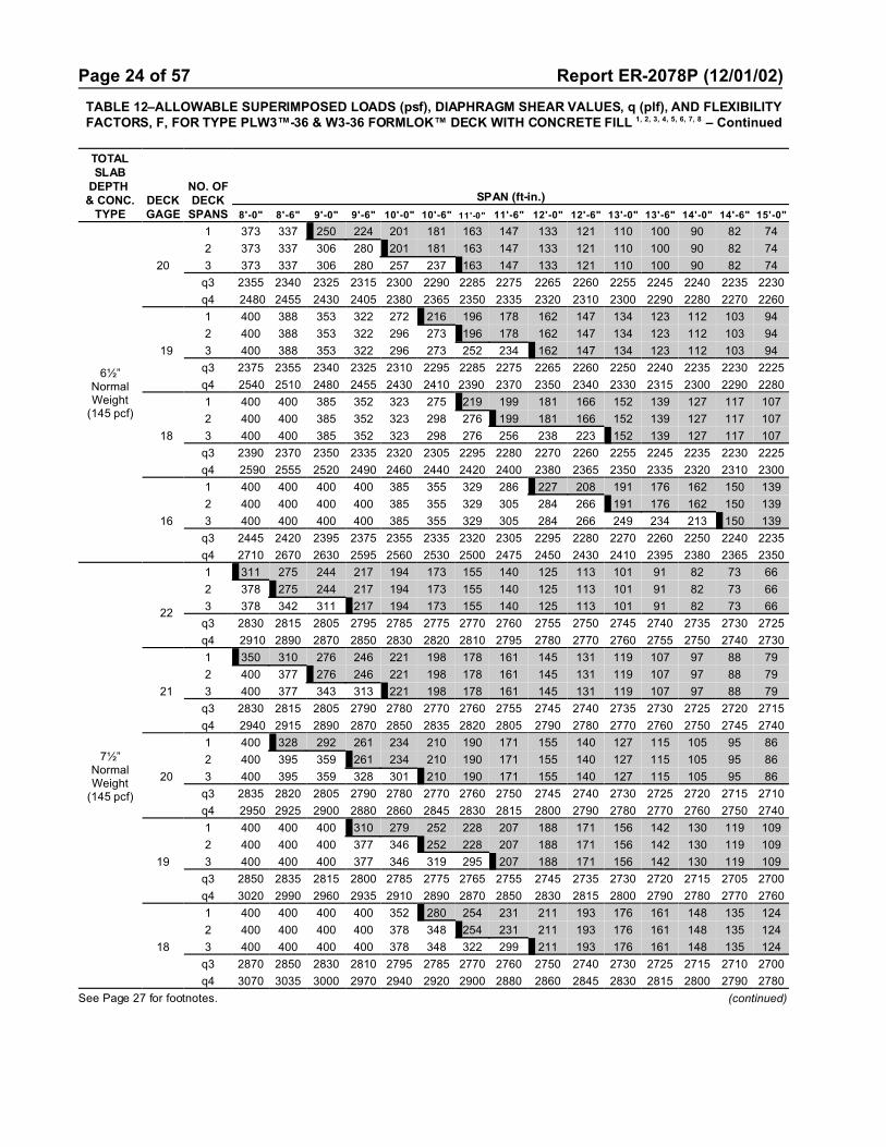
Page 24 of 57 Report ER-2078P (12/01/02)
TABLE 12–ALLOWABLE SUPERIMPOSED LOADS (psf), DIAPHRAGM SHEAR VALUES, q (plf), AND FLEXIBILITYFACTORS, F, FOR TYPE PLW3™-36 & W3-36 FORMLOK™ DECK WITH CONCRETE FILL 1, 2, 3, 4, 5, 6, 7, 8 – Continued
TOTALSLAB
DEPTH & CONC.
TYPEDECKGAGE
NO. OFDECK
SPANS
SPAN (ft-in.)
8'-0" 8'-6" 9'-0" 9'-6" 10'-0" 10'-6" 11'-0" 11'-6" 12'-0" 12'-6" 13'-0" 13'-6" 14'-0" 14'-6" 15'-0"
6½”NormalWeight
(145 pcf)
20
1 373 337 250 224 201 181 163 147 133 121 110 100 90 82 74
2 373 337 306 280 201 181 163 147 133 121 110 100 90 82 74
3 373 337 306 280 257 237 163 147 133 121 110 100 90 82 74
q3 2355 2340 2325 2315 2300 2290 2285 2275 2265 2260 2255 2245 2240 2235 2230
q4 2480 2455 2430 2405 2380 2365 2350 2335 2320 2310 2300 2290 2280 2270 2260
19
1 400 388 353 322 272 216 196 178 162 147 134 123 112 103 94
2 400 388 353 322 296 273 196 178 162 147 134 123 112 103 94
3 400 388 353 322 296 273 252 234 162 147 134 123 112 103 94
q3 2375 2355 2340 2325 2310 2295 2285 2275 2265 2260 2250 2240 2235 2230 2225
q4 2540 2510 2480 2455 2430 2410 2390 2370 2350 2340 2330 2315 2300 2290 2280
18
1 400 400 385 352 323 275 219 199 181 166 152 139 127 117 107
2 400 400 385 352 323 298 276 199 181 166 152 139 127 117 107
3 400 400 385 352 323 298 276 256 238 223 152 139 127 117 107
q3 2390 2370 2350 2335 2320 2305 2295 2280 2270 2260 2255 2245 2235 2230 2225
q4 2590 2555 2520 2490 2460 2440 2420 2400 2380 2365 2350 2335 2320 2310 2300
16
1 400 400 400 400 385 355 329 286 227 208 191 176 162 150 139
2 400 400 400 400 385 355 329 305 284 266 191 176 162 150 139
3 400 400 400 400 385 355 329 305 284 266 249 234 213 150 139
q3 2445 2420 2395 2375 2355 2335 2320 2305 2295 2280 2270 2260 2250 2240 2235
q4 2710 2670 2630 2595 2560 2530 2500 2475 2450 2430 2410 2395 2380 2365 2350
7½”NormalWeight
(145 pcf)
22
1 311 275 244 217 194 173 155 140 125 113 101 91 82 73 66
2 378 275 244 217 194 173 155 140 125 113 101 91 82 73 66
3 378 342 311 217 194 173 155 140 125 113 101 91 82 73 66
q3 2830 2815 2805 2795 2785 2775 2770 2760 2755 2750 2745 2740 2735 2730 2725
q4 2910 2890 2870 2850 2830 2820 2810 2795 2780 2770 2760 2755 2750 2740 2730
21
1 350 310 276 246 221 198 178 161 145 131 119 107 97 88 79
2 400 377 276 246 221 198 178 161 145 131 119 107 97 88 79
3 400 377 343 313 221 198 178 161 145 131 119 107 97 88 79
q3 2830 2815 2805 2790 2780 2770 2760 2755 2745 2740 2735 2730 2725 2720 2715
q4 2940 2915 2890 2870 2850 2835 2820 2805 2790 2780 2770 2760 2750 2745 2740
20
1 400 328 292 261 234 210 190 171 155 140 127 115 105 95 86
2 400 395 359 261 234 210 190 171 155 140 127 115 105 95 86
3 400 395 359 328 301 210 190 171 155 140 127 115 105 95 86
q3 2835 2820 2805 2790 2780 2770 2760 2750 2745 2740 2730 2725 2720 2715 2710
q4 2950 2925 2900 2880 2860 2845 2830 2815 2800 2790 2780 2770 2760 2750 2740
19
1 400 400 400 310 279 252 228 207 188 171 156 142 130 119 109
2 400 400 400 377 346 252 228 207 188 171 156 142 130 119 109
3 400 400 400 377 346 319 295 207 188 171 156 142 130 119 109
q3 2850 2835 2815 2800 2785 2775 2765 2755 2745 2735 2730 2720 2715 2705 2700
q4 3020 2990 2960 2935 2910 2890 2870 2850 2830 2815 2800 2790 2780 2770 2760
18
1 400 400 400 400 352 280 254 231 211 193 176 161 148 135 124
2 400 400 400 400 378 348 254 231 211 193 176 161 148 135 124
3 400 400 400 400 378 348 322 299 211 193 176 161 148 135 124
q3 2870 2850 2830 2810 2795 2785 2770 2760 2750 2740 2730 2725 2715 2710 2700
q4 3070 3035 3000 2970 2940 2920 2900 2880 2860 2845 2830 2815 2800 2790 2780
See Page 27 for footnotes. (continued)

Page 25 of 57 Report ER-2078P (12/01/02)
TABLE 12–ALLOWABLE SUPERIMPOSED LOADS (psf), DIAPHRAGM SHEAR VALUES, q (plf), AND FLEXIBILITYFACTORS, F, FOR TYPE PLW3™-36 & W3-36 FORMLOK™ DECK WITH CONCRETE FILL 1, 2, 3, 4, 5, 6, 7, 8 – Continued
TOTALSLAB
DEPTH & CONC.
TYPEDECKGAGE
NO. OFDECK
SPANS
SPAN (ft-in.)
8'-0" 8'-6" 9'-0" 9'-6" 10'-0" 10'-6" 11'-0" 11'-6" 12'-0" 12'-6" 13'-0" 13'-6" 14'-0" 14'-6" 15'-0"
7½”NormalWeight
(145 pcf)
16
1 400 400 400 400 400 400 363 288 263 242 222 204 188 174 160
2 400 400 400 400 400 400 384 356 263 242 222 204 188 174 160
3 400 400 400 400 400 400 384 356 332 310 290 204 188 174 160
q3 2925 2895 2875 2850 2835 2815 2800 2785 2770 2760 2750 2740 2730 2720 2710
q4 3190 3150 3110 3075 3040 3010 2980 2955 2930 2910 2890 2875 2860 2845 2830
5"Structural
LightWeight
(110 pcf)
22
1 246 223 202 185 139 126 114 104 95 87 79 73 66 61 56
2 246 223 202 185 170 157 114 104 95 87 79 73 66 61 56
3 246 223 202 185 170 157 145 131 95 87 79 73 66 61 56
q3 1310 1295 1285 1275 1265 1255 1250 1240 1235 1230 1225 1220 1215 1210 1205
q4 1390 1370 1350 1330 1310 1300 1290 1275 1260 1250 1240 1235 1230 1220 1210
21
1 273 247 224 205 188 161 130 119 108 99 91 84 77 71 65
2 273 247 224 205 188 174 161 149 108 99 91 84 77 71 65
3 273 247 224 205 188 174 161 149 136 123 91 84 77 71 65
q3 1310 1295 1285 1270 1260 1250 1240 1235 1225 1220 1215 1210 1205 1200 1195
q4 1420 1395 1370 1350 1330 1315 1300 1285 1270 1260 1250 1240 1230 1225 1220
20
1 286 259 235 215 197 177 150 126 115 105 97 89 82 75 70
2 286 259 235 215 197 182 168 156 146 105 97 89 82 75 70
3 286 259 235 215 197 182 168 156 146 132 120 89 82 75 70
q3 1315 1300 1285 1270 1260 1250 1240 1235 1225 1220 1210 1205 1200 1195 1190
q4 1430 1405 1380 1360 1340 1325 1310 1295 1280 1270 1260 1250 1240 1230 1220
19
1 331 299 272 249 228 211 195 172 148 126 116 107 99 92 85
2 331 299 272 249 228 211 195 181 169 152 135 107 99 92 85
3 331 299 272 249 228 211 195 181 169 152 135 120 108 97 85
q3 1330 1315 1295 1280 1265 1255 1245 1235 1225 1215 1210 1200 1195 1190 1180
q4 1500 1470 1440 1415 1390 1370 1350 1330 1310 1295 1280 1270 1260 1250 1240
18
1 363 328 298 273 250 231 213 198 176 152 131 120 111 102 92
2 363 328 298 273 250 231 213 198 180 159 141 126 113 102 92
3 363 328 298 273 250 231 213 198 180 159 141 126 113 102 92
q3 1350 1330 1310 1295 1275 1265 1250 1240 1230 1220 1210 1205 1195 1190 1180
q4 1550 1515 1480 1450 1420 1400 1380 1360 1340 1325 1310 1295 1280 1270 1260
16
1 400 395 353 314 280 251 226 204 185 168 153 140 125 113 102
2 400 395 353 314 280 251 226 204 185 168 153 140 125 113 102
3 400 395 353 314 280 251 226 204 185 168 153 140 125 113 102
q3 1405 1375 1355 1330 1315 1295 1280 1265 1250 1240 1230 1220 1210 1200 1190
q4 1670 1630 1590 1555 1520 1490 1460 1435 1410 1390 1370 1355 1340 1325 1310
5½”Structural
LightWeight
(110 pcf)
22
1 270 244 222 168 152 137 124 113 103 94 86 78 72 66 60
2 270 244 222 203 186 137 124 113 103 94 86 78 72 66 60
3 270 244 222 203 186 172 159 113 103 94 86 78 72 66 60
q3 1465 1455 1440 1430 1425 1415 1405 1400 1395 1385 1380 1375 1370 1365 1365
q4 1550 1530 1510 1490 1470 1455 1440 1430 1420 1410 1400 1390 1380 1375 1370
21
1 299 270 246 225 205 155 141 129 117 107 98 90 83 76 70
2 299 270 246 225 206 190 176 129 117 107 98 90 83 76 70
3 299 270 246 226 206 190 176 163 152 107 98 90 83 76 70
q3 1470 1455 1440 1430 1420 1410 1400 1390 1385 1380 1370 1365 1360 1355 1350
q4 1580 1555 1530 1510 1490 1475 1460 1445 1430 1420 1410 1400 1390 1380 1370
See Page 27 for footnotes. (continued)

Page 26 of 57 Report ER-2078P (12/01/02)
TABLE 12–ALLOWABLE SUPERIMPOSED LOADS (psf), DIAPHRAGM SHEAR VALUES, q (plf), AND FLEXIBILITYFACTORS, F, FOR TYPE PLW3™-36 & W3-36 FORMLOK™ DECK WITH CONCRETE FILL 1, 2, 3, 4, 5, 6, 7, 8 – Continued
TOTALSLAB
DEPTH & CONC.
TYPEDECKGAGE
NO. OFDECK
SPANS
SPAN (ft-in.)
8'-0" 8'-6" 9'-0" 9'-6" 10'-0" 10'-6" 11'-0" 11'-6" 12'-0" 12'-6" 13'-0" 13'-6" 14'-0" 14'-6" 15'-0"
5½”Structural
LightWeight
(110 pcf)
20
1 313 283 257 235 216 190 149 136 124 114 105 96 88 81 75
2 313 283 257 235 216 199 184 171 124 114 105 96 88 81 75
3 313 283 257 235 216 199 184 171 159 148 105 96 88 81 75
q3 1470 1455 1440 1430 1420 1410 1400 1390 1385 1375 1370 1365 1355 1350 1345
q4 1590 1565 1540 1520 1500 1485 1470 1455 1440 1430 1420 1410 1400 1390 1380
1 362 327 297 272 249 230 213 184 156 137 126 116 107 99 92
2 362 327 297 272 249 230 213 197 184 172 126 116 107 99 92
19 3 362 327 297 272 249 230 213 197 184 172 161 151 134 99 92
q3 1490 1470 1455 1440 1425 1415 1400 1390 1385 1375 1365 1360 1350 1345 1340
q4 1650 1620 1590 1565 1540 1520 1500 1485 1470 1455 1440 1430 1420 1410 1400
18
1 395 357 325 297 273 251 233 216 189 162 141 130 120 111 103
2 395 357 325 297 273 251 233 216 201 188 176 164 120 111 103
3 395 357 325 297 273 251 233 216 201 188 176 164 147 132 103
q3 1510 1485 1465 1450 1435 1420 1410 1400 1385 1380 1370 1360 1355 1345 1340
q4 1700 1665 1630 1605 1580 1560 1540 1520 1500 1485 1470 1455 1440 1430 1420
16
1 400 400 389 356 327 301 279 259 241 225 203 162 150 140 130
2 400 400 389 356 327 301 279 259 241 225 203 181 162 146 130
3 400 400 389 356 327 301 279 259 241 225 203 181 162 146 132
q3 1560 1535 1510 1490 1470 1455 1440 1425 1410 1400 1385 1375 1365 1360 1350
q4 1830 1785 1740 1705 1670 1645 1620 1595 1570 1550 1530 1515 1500 1485 1470
6¼”Structural
LightWeight
(110 pcf)
22
1 309 279 213 191 172 155 141 128 116 106 97 88 81 74 68
2 309 279 254 232 172 155 141 128 116 106 97 88 81 74 68
3 309 279 254 232 213 196 141 128 116 106 97 88 81 74 68
q3 1705 1690 1680 1670 1660 1650 1645 1635 1630 1625 1620 1615 1610 1605 1600
q4 1780 1760 1740 1725 1710 1695 1680 1670 1660 1650 1640 1630 1620 1615 1610
21
1 341 309 281 256 194 176 160 145 133 121 111 102 93 86 79
2 341 309 281 256 235 217 160 145 133 121 111 102 93 86 79
3 341 309 281 256 235 217 201 186 133 121 111 102 93 86 79
q3 1705 1690 1680 1665 1655 1645 1635 1630 1620 1615 1610 1605 1600 1595 1590
q4 1810 1790 1770 1750 1730 1715 1700 1685 1670 1660 1650 1640 1630 1620 1610
20
1 357 323 294 268 246 186 169 154 141 129 118 108 100 92 84
2 357 323 294 268 246 227 210 154 141 129 118 108 100 92 84
3 357 323 294 268 246 227 210 195 182 129 118 108 100 92 84
q3 1710 1695 1680 1665 1655 1645 1635 1630 1620 1615 1605 1600 1595 1590 1585
q4 1830 1805 1780 1760 1740 1720 1700 1690 1680 1665 1650 1640 1630 1620 1610
19
1 400 372 338 309 284 262 235 183 168 154 142 131 121 111 103
2 400 372 338 309 284 262 242 225 209 154 142 131 121 111 103
3 400 372 338 309 284 262 242 225 209 196 183 131 121 111 103
q3 1725 1710 1690 1675 1660 1650 1640 1630 1620 1610 1605 1595 1590 1580 1575
q4 1890 1860 1830 1805 1780 1760 1740 1725 1710 1695 1680 1670 1660 1645 1630
18
1 400 400 369 338 310 286 264 241 203 172 158 146 135 125 116
2 400 400 369 338 310 286 264 246 229 214 158 146 135 125 116
3 400 400 369 338 310 286 264 246 229 214 200 188 176 125 116
q3 1745 1725 1705 1690 1670 1660 1645 1635 1625 1615 1605 1600 1590 1585 1575
q4 1940 1905 1870 1845 1820 1795 1770 1750 1730 1715 1700 1690 1680 1665 1650
See Page 27 for footnotes. (continued)

Page 27 of 57 Report ER-2078P (12/01/02)
TABLE 12–ALLOWABLE SUPERIMPOSED LOADS (psf), DIAPHRAGM SHEAR VALUES, q (plf), AND FLEXIBILITYFACTORS, F, FOR TYPE PLW3™-36 & W3-36 FORMLOK™ DECK WITH CONCRETE FILL 1, 2, 3, 4, 5, 6, 7, 8 – Continued
TOTALSLAB
DEPTH & CONC.
TYPEDECKGAGE
NO. OFDECK
SPANS
SPAN (ft-in.)
8'-0" 8'-6" 9'-0" 9'-6" 10'-0" 10'-6" 11'-0" 11'-6" 12'-0" 12'-6" 13'-0" 13'-6" 14'-0" 14'-6" 15'-0"
6¼”Structural
LightWeight
(110 pcf)
16
1 400 400 400 400 370 341 316 293 273 255 197 182 169 157 146
2 400 400 400 400 370 341 316 293 273 255 239 224 211 157 146
3 400 400 400 400 370 341 316 293 273 255 239 224 211 199 188
q3 1800 1770 1750 1725 1710 1690 1675 1660 1645 1635 1625 1615 1605 1595 1585
q4 2070 2025 1980 1945 1910 1880 1850 1830 1810 1790 1770 1750 1730 1715 1700
7¼”Structural
LightWeight
(110 pcf)
22
1 364 280 250 224 202 182 165 150 136 124 113 103 94 86 79
2 364 329 299 224 202 182 165 150 136 124 113 103 94 86 79
3 364 329 299 273 251 182 165 150 136 124 113 103 94 86 79
q3 2020 2005 1995 1985 1975 1965 1960 1950 1945 1940 1935 1930 1925 1920 1915
q4 2100 2080 2060 2040 2020 2010 2000 1985 1970 1960 1950 1945 1940 1930 1920
21
1 400 363 281 253 228 206 187 170 155 142 130 119 109 100 92
2 400 363 330 302 277 206 187 170 155 142 130 119 109 100 92
3 400 363 330 302 277 255 236 170 155 142 130 119 109 100 92
q3 2020 2005 1995 1980 1970 1960 1955 1945 1940 1930 1925 1920 1915 1910 1905
q4 2130 2125 2080 2060 2040 2025 2010 1995 1980 1970 1960 1950 1940 1935 1930
20
1 400 380 345 266 240 218 198 180 165 150 138 126 116 107 98
2 400 380 345 316 290 218 198 180 165 150 138 126 116 107 98
3 400 380 345 316 290 267 247 230 165 150 138 126 116 107 98
q3 2025 2010 1995 1985 1970 1960 1950 1945 1935 1930 1920 1915 1910 1905 1900
q4 2150 2120 2090 2070 2050 2035 2020 2005 1990 1980 1970 1960 1950 1940 1930
19
1 400 400 397 363 333 304 235 214 196 180 166 153 141 130 120
2 400 400 397 363 333 307 285 214 196 180 166 153 141 130 120
3 400 400 397 363 333 307 285 264 246 230 166 153 141 130 120
q3 2045 2025 2005 1990 1980 1965 1955 1945 1935 1925 1920 1910 1905 1900 1890
q4 2210 2180 2150 2125 2100 2080 2060 2040 2020 2010 2000 1985 1970 1960 1950
18
1 400 400 400 396 364 335 310 238 218 201 185 171 158 146 135
2 400 400 400 396 364 335 310 288 268 201 185 171 158 146 135
3 400 400 400 396 364 335 310 288 268 251 235 171 158 146 135
q3 2060 2040 2020 2005 1990 1975 1960 1950 1940 1930 1920 1915 1905 1900 1890
q4 2260 2225 2190 2160 2130 2110 2090 2070 2050 2035 2020 2005 1990 1980 1970
16
1 400 400 400 400 400 399 370 343 320 248 229 212 197 183 170
2 400 400 400 400 400 399 370 343 320 299 280 212 197 183 170
3 400 400 400 400 400 399 370 343 320 299 280 263 247 233 170
q3 2115 2085 2065 2045 2025 2005 1990 1975 1965 1950 1940 1930 1920 1910 1905
q4 2380 2340 2300 2265 2230 2200 2170 2145 2120 2100 2080 2065 2050 2035 2020
1 Shoring calculations based on deck supporting dead load of concrete plus either 20 psf uniform construction live load or 150-poundconcentrated live load for flexure. Dead load deflection limited to L/180 of span length, but not to exceed 3/4 inch.
2 Shoring is required at midspan for superimposed load values to the right of the heavy line.3 Steel for deck to have a minimum yield strength of 38,000 psi.4 Total slab depth is nominal depth from top of concrete to bottom of steel deck.5 Concrete fill to have minimum compressive strength fNc = 3000 psi.6 Support reactions for unshored spans due to dead loads and uniform construction live loads may not exceed values set forth in Table 5.7 The number after the letter q indicates the number of puddle welds per panel end and at interior supports.8 PLW3-36 and W3-36 FORMLOK decks with structural concrete fill may be considered rigid diaphragm, with F<1.

Page 28 of 57 Report ER-2078P (12/01/02)
TABLE 13–ALLOWABLE SUPERIMPOSED LOADS (psf), DIAPHRAGM SHEAR VALUES, q (plf), AND FLEXIBILITYFACTORS, F, FOR TYPE PLN™-24 & N-24 FORMLOK™ DECK WITH CONCRETE FILL 1, 2, 3, 4, 5, 6, 7
TOTALSLAB
DEPTH& CONC.
TYPEDECKGAGE
NO. OFDECK
SPANS
SPAN (ft-in.)
8'-0" 8'-6" 9'-0" 9'-6" 10'-0" 10'-6" 11'-0" 11'-6" 12'-0" 12'-6" 13'-0" 13'-6" 14'-0" 14'-6" 15'-0"
5"NormalWeight
(145 pcf)
22
1 241 211 165 148 133 120 109 99 90 82 74 68 62 – –
2 241 218 198 181 166 145 109 99 90 82 74 68 62 – –
3 241 218 198 181 166 145 109 99 90 82 74 68 62 – –
q4 1700 1675 1660 1640 1625 1610 1600 1585 1575 1565 1555 1550 1540 – –
F4 1.10 1.11 1.13 1.14 1.15 1.16 1.17 1.18 1.18 1.19 1.20 1.21 1.21 – –
20
1 255 230 209 191 142 129 117 106 96 88 80 73 67 61 56
2 255 230 209 191 176 162 150 139 96 88 80 73 67 61 56
3 255 230 209 191 176 162 150 139 122 88 80 73 67 61 56
q4 1740 1715 1690 1670 1650 1635 1620 1605 1590 1580 1570 1560 1550 1540 1535
F4 0.98 0.99 1.01 1.02 1.03 1.04 1.05 1.06 1.07 1.08 1.08 1.09 1.10 1.10 1.11
18
1 257 232 211 193 177 163 151 140 128 88 80 73 67 61 56
2 257 232 211 193 177 163 151 140 131 122 114 73 67 61 56
3 257 232 211 193 177 163 151 140 131 122 114 107 101 95 56
q4 1840 1805 1775 1750 1725 1700 1680 1660 1645 1630 1615 1600 1590 1575 1565
F4 0.80 0.82 0.83 0.84 0.86 0.87 0.88 0.89 0.90 0.91 0.91 0.92 0.93 0.94 0.94
16
1 259 234 213 194 178 165 152 141 132 123 115 108 67 61 56
2 259 234 213 194 178 165 152 141 132 123 115 108 102 96 56
3 259 234 213 194 178 165 152 141 132 123 115 108 102 96 91
q4 1960 1915 1875 1840 1810 1785 1760 1735 1715 1695 1675 1660 1640 1630 1615
F4 0.67 0.69 0.70 0.72 0.73 0.74 0.75 0.76 0.77 0.78 0.79 0.80 0.80 0.81 0.82
5½”NormalWeight
(145 pcf)
22
1 263 200 178 160 143 129 117 106 96 87 79 72 65 – –
2 263 238 217 198 182 129 117 106 96 87 79 72 65 – –
3 263 238 217 198 182 129 117 106 96 87 79 72 65 – –
q4 1940 1915 1895 1880 1865 1850 1835 1825 1815 1805 1795 1785 1780 – –
F4 0.96 0.97 0.98 0.99 1.00 1.01 1.02 1.02 1.03 1.03 1.04 1.04 1.05 – –
20
1 278 251 229 170 153 138 125 113 103 94 85 78 71 65 59
2 278 251 229 209 192 177 164 113 103 94 85 78 71 65 59
3 278 251 229 209 192 177 164 152 103 94 85 78 71 65 59
q4 1980 1955 1930 1910 1890 1870 1860 1845 1830 1820 1810 1800 1790 1780 1770
F4 0.86 0.87 0.88 0.89 0.90 0.91 0.92 0.92 0.93 0.94 0.94 0.95 0.95 0.96 0.96
18
1 278 252 229 209 192 177 164 152 102 93 85 77 70 64 58
2 278 252 229 209 192 177 164 152 142 132 85 77 70 64 58
3 278 252 229 209 192 177 164 152 142 132 124 116 110 64 58
q4 2080 2045 2015 1990 1965 1940 1920 1900 1885 1870 1855 1840 1830 1815 1805
F4 0.71 0.72 0.73 0.74 0.75 0.76 0.77 0.78 0.78 0.79 0.80 0.80 0.81 0.81 0.82
16
1 279 252 229 210 192 177 164 152 142 133 124 77 70 63 58
2 279 252 229 210 192 177 164 152 142 133 124 117 110 63 58
3 279 252 229 210 192 177 164 152 142 133 124 117 110 104 98
q4 2200 2155 2115 2080 2050 2020 1995 1975 1950 1930 1915 1895 1880 1865 1855
F4 0.60 0.61 0.62 0.63 0.64 0.65 0.66 0.67 0.68 0.68 0.69 0.70 0.70 0.71 0.71
6"NormalWeight
(145 pcf)
22
1 245 217 194 173 155 140 126 114 103 94 85 77 – – –
2 289 261 237 217 155 140 126 114 103 94 85 77 – – –
3 289 261 237 217 155 140 126 114 103 94 85 77 – – –
q4 2175 2155 2135 2120 2105 2090 2075 2065 2055 2045 2035 2025 – – –
F4 0.86 0.87 0.87 0.88 0.89 0.89 0.90 0.90 0.91 0.91 0.92 0.92 – – –
20
1 300 275 250 184 166 149 135 122 111 101 91 83 76 69 63
2 300 275 250 229 210 193 135 122 111 101 91 83 76 69 63
3 300 275 250 229 210 193 179 122 111 101 91 83 76 69 63
q4 2220 2190 2170 2150 2130 2115 2095 2085 2070 2060 2050 2040 2030 2020 2010
F4 0.77 0.78 0.79 0.79 0.80 0.81 0.81 0.82 0.82 0.83 0.83 0.84 0.84 0.84 0.85
See Page 31 for footnotes. (continued)

Page 29 of 57 Report ER-2078P (12/01/02)
TABLE 13–ALLOWABLE SUPERIMPOSED LOADS (psf), DIAPHRAGM SHEAR VALUES, q (plf), AND FLEXIBILITYFACTORS, F, FOR TYPE PLN™-24 & N-24 FORMLOK™ DECK WITH CONCRETE FILL 1, 2, 3, 4, 5, 6, 7 – Continued
TOTALSLAB
DEPTH& CONC.
TYPEDECKGAGE
NO. OFDECK
SPANS
SPAN (ft-in.)
8'-0" 8'-6" 9'-0" 9'-6" 10'-0" 10'-6" 11'-0" 11'-6" 12'-0" 12'-6" 13'-0" 13'-6" 14'-0" 14'-6" 15'-0"
6"NormalWeight
(145 pcf)
18
1 300 274 249 228 209 193 134 121 110 99 90 82 75 68 62
2 300 274 249 228 209 193 178 166 154 99 90 82 75 68 62
3 300 274 249 228 209 193 178 166 154 144 135 127 75 68 62
q4 2320 2285 2255 2230 2200 2180 2160 2140 2125 2105 2095 2080 2065 2055 2045
F4 0.64 0.65 0.65 0.66 0.67 0.68 0.68 0.69 0.70 0.70 0.71 0.71 0.71 0.72 0.72
16
1 300 274 249 228 209 193 178 165 154 144 89 81 74 67 61
2 300 274 249 228 209 193 178 165 154 144 135 127 74 67 61
3 300 274 249 228 209 193 178 165 154 144 135 127 119 112 61
q4 2435 2395 2355 2320 2290 2260 2235 2210 2190 2170 2155 2135 2120 2105 2090
F4 0.54 0.55 0.56 0.57 0.58 0.58 0.59 0.60 0.60 0.61 0.61 0.62 0.62 0.63 0.63
6½”NormalWeight
(145 pcf)
22
1 267 236 210 188 169 152 137 123 112 101 91 83 – – –
2 300 286 260 188 169 152 137 123 112 101 91 83 – – –
3 300 286 260 188 169 152 137 123 112 101 91 83 – – –
q4 2415 2395 2375 2360 2340 2330 2315 2305 2295 2285 2275 2265 – – –
F4 0.77 0.78 0.79 0.79 0.80 0.80 0.81 0.81 0.81 0.82 0.82 0.82 – – –
20
1 300 300 224 200 180 162 146 132 120 108 98 89 81 74 67
2 300 300 273 250 229 162 146 132 120 108 98 89 81 74 67
3 300 300 273 250 229 211 146 132 120 108 98 89 81 74 67
q4 2460 2430 2410 2390 2370 2350 2335 2325 2310 2300 2285 2275 2265 2260 2250
F4 0.69 0.70 0.71 0.71 0.72 0.72 0.73 0.73 0.74 0.74 0.74 0.75 0.75 0.75 0.76
18
1 300 299 272 248 228 210 144 130 118 107 97 88 80 72 66
2 300 299 272 248 228 210 194 181 118 107 97 88 80 72 66
3 300 299 272 248 228 210 194 181 168 157 97 88 80 72 66
q4 2560 2525 2495 2465 2440 2420 2400 2380 2360 2345 2330 2320 2305 2295 2285
F4 0.58 0.58 0.59 0.60 0.60 0.61 0.62 0.62 0.62 0.63 0.63 0.64 0.64 0.64 0.65
16
1 300 298 271 247 227 209 194 180 167 105 96 87 79 71 64
2 300 298 271 247 227 209 194 180 167 156 96 87 79 71 64
3 300 298 271 247 227 209 194 180 167 156 147 138 130 71 64
q4 2675 2635 2595 2560 2530 2500 2475 2450 2430 2410 2390 2375 2360 2345 2330
F4 0.49 0.50 0.51 0.52 0.52 0.53 0.53 0.54 0.54 0.55 0.55 0.56 0.56 0.56 0.57
7½”NormalWeight
(145 pcf)
22
1 300 277 247 220 197 177 159 144 130 117 106 96 87 – –
2 300 300 247 220 197 177 159 144 130 117 106 96 87 – –
3 300 300 247 220 197 177 159 144 130 117 106 96 87 – –
q4 2895 2870 2855 2835 2820 2805 2795 2780 2770 2760 2750 2745 2735 – –
F4 0.64 0.65 0.65 0.66 0.66 0.67 0.67 0.67 0.67 0.68 0.68 0.68 0.68 – –
20
1 300 294 262 234 210 189 170 154 139 126 114 103 94 85 77
2 300 300 300 295 210 189 170 154 139 126 114 103 94 85 77
3 300 300 300 295 270 189 170 154 139 126 114 103 94 85 77
q4 2935 2910 2885 2865 2845 2830 2815 2800 2790 2775 2765 2755 2745 2735 2730
F4 0.58 0.59 0.59 0.59 0.60 0.60 0.61 0.61 0.61 0.61 0.62 0.62 0.62 0.62 0.62
18
1 300 300 300 292 207 186 168 151 137 124 112 101 92 83 75
2 300 300 300 292 268 247 168 151 137 124 112 101 92 83 75
3 300 300 300 292 268 247 229 212 198 124 112 101 92 83 75
q4 3035 3005 2970 2945 2920 2895 2875 2860 2840 2825 2810 2795 2785 2775 2760
F4 0.49 0.49 0.50 0.50 0.51 0.51 0.51 0.52 0.52 0.52 0.53 0.53 0.53 0.53 0.53
16
1 300 300 300 290 266 245 227 149 135 122 110 100 90 81 74
2 300 300 300 290 266 245 227 211 196 122 110 100 90 81 74
3 300 300 300 290 266 245 227 211 196 184 172 100 90 81 74
q4 3155 3110 3070 3040 3005 2980 2955 2930 2910 2890 2870 2855 2840 2825 2810
F4 0.42 0.42 0.43 0.43 0.44 0.44 0.45 0.45 0.45 0.46 0.46 0.46 0.47 0.47 0.47
See Page 31 for footnotes. (continued)

Page 30 of 57 Report ER-2078P (12/01/02)
TABLE 13–ALLOWABLE SUPERIMPOSED LOADS (psf), DIAPHRAGM SHEAR VALUES, q (plf), AND FLEXIBILITYFACTORS, F, FOR TYPE PLN™-24 & N-24 FORMLOK™ DECK WITH CONCRETE FILL 1, 2, 3, 4, 5, 6, 7 – Continued
TOTALSLAB
DEPTH& CONC.
TYPEDECKGAGE
NO. OFDECK
SPANS
SPAN (ft-in.)
8'-0" 8'-6" 9'-0" 9'-6" 10'-0" 10'-6" 11'-0" 11'-6" 12'-0" 12'-6" 13'-0" 13'-6" 14'-0" 14'-6" 15'-0"
5"Structural
LightWeight
(110 pcf)
22
1 241 218 198 155 141 128 116 106 97 89 82 75 69 64 59
2 241 218 198 181 166 153 142 125 97 89 82 75 69 64 59
3 241 218 198 181 166 153 142 125 97 89 82 75 69 64 59
q4 1375 1355 1335 1315 1300 1285 1275 1260 1250 1240 1230 1225 1215 1210 1200
F4 1.36 1.38 1.40 1.42 1.43 1.45 1.47 1.48 1.49 1.50 1.51 1.52 1.53 1.54 1.55
20
1 255 230 209 191 176 162 124 113 104 95 88 81 75 69 64
2 255 230 209 191 176 162 150 139 130 119 88 81 75 69 64
3 255 230 209 191 176 162 150 139 130 119 105 94 75 69 64
q4 1415 1390 1365 1345 1325 1310 1295 1280 1270 1255 1245 1235 1225 1215 1210
F4 1.20 1.23 1.25 1.27 1.28 1.30 1.32 1.33 1.34 1.36 1.37 1.38 1.39 1.40 1.41
18
1 257 232 211 193 177 163 151 140 131 122 114 81 75 69 64
2 257 232 211 193 177 163 151 140 131 122 114 107 97 87 64
3 257 232 211 193 177 163 151 140 131 122 114 107 97 87 78
q4 1520 1485 1450 1425 1400 1375 1355 1340 1320 1305 1290 1275 1265 1255 1240
F4 0.97 1.00 1.02 1.04 1.05 1.07 1.09 1.10 1.12 1.13 1.14 1.16 1.17 1.18 1.19
16
1 259 234 213 194 178 165 152 141 132 123 115 108 102 96 64
2 259 234 213 194 178 165 152 141 132 123 115 108 102 96 87
3 259 234 213 194 178 165 152 141 132 123 115 108 102 96 87
q4 1635 1590 1555 1520 1485 1460 1435 1410 1390 1370 1350 1335 1320 1305 1290
F4 0.81 0.83 0.85 0.87 0.89 0.90 0.92 0.94 0.95 0.96 0.98 0.99 1.00 1.01 1.02
5½”Structural
LightWeight
(110 pcf)
22
1 263 238 187 168 152 138 125 114 105 96 88 81 74 68 63
2 263 238 217 198 182 167 155 114 105 96 88 81 74 68 63
3 263 238 217 198 182 167 155 114 105 96 88 81 74 68 63
q4 1530 1510 1490 1475 1460 1445 1430 1420 1410 1400 1390 1380 1375 1365 1360
F4 1.22 1.24 1.25 1.27 1.28 1.29 1.30 1.31 1.32 1.33 1.34 1.35 1.36 1.37 1.37
20
1 278 251 229 209 192 147 134 122 112 102 94 86 80 73 68
2 278 251 229 209 192 177 164 152 142 102 94 86 80 73 68
3 278 251 229 209 192 177 164 152 142 132 94 86 80 73 68
q4 1575 1550 1525 1505 1485 1470 1455 1440 1425 1415 1405 1395 1385 1375 1365
F4 1.08 1.10 1.12 1.13 1.15 1.16 1.17 1.18 1.19 1.20 1.21 1.22 1.23 1.24 1.25
18
1 278 252 229 209 192 177 164 152 142 132 93 86 79 73 67
2 278 252 229 209 192 177 164 152 142 132 124 116 79 73 67
3 278 252 229 209 192 177 164 152 142 132 124 116 110 103 98
q4 1675 1640 1610 1580 1555 1535 1515 1495 1480 1465 1450 1435 1420 1410 1400
F4 0.88 0.90 0.92 0.93 0.95 0.96 0.97 0.99 1.00 1.01 1.02 1.03 1.04 1.05 1.05
16
1 279 252 229 210 192 177 164 152 142 133 124 117 110 72 67
2 279 252 229 210 192 177 164 152 142 133 124 117 110 104 98
3 279 252 229 210 192 177 164 152 142 133 124 117 110 104 98
q4 1795 1750 1710 1675 1645 1615 1590 1570 1545 1525 1510 1490 1475 1460 1450
F4 0.74 0.75 0.77 0.79 0.80 0.82 0.83 0.84 0.85 0.86 0.87 0.88 0.89 0.90 0.91
6¼”Structural
LightWeight
(110 pcf)
22
1 300 238 213 191 173 156 142 129 118 108 99 91 83 76 70
2 300 273 248 227 208 156 142 129 118 108 99 91 83 76 70
3 300 273 248 227 208 156 142 129 118 108 99 91 83 76 70
q4 1770 1750 1730 1710 1695 1680 1670 1655 1645 1635 1625 1620 1610 1605 1595
F4 1.05 1.07 1.08 1.09 1.10 1.11 1.12 1.13 1.13 1.14 1.15 1.15 1.16 1.16 1.17
20
1 300 288 261 239 183 166 151 138 126 115 106 97 89 82 76
2 300 288 261 239 219 202 187 138 126 115 106 97 89 82 76
3 300 288 261 239 219 202 187 174 162 115 106 97 89 82 76
q4 1810 1785 1760 1740 1720 1705 1690 1675 1665 1650 1640 1630 1620 1610 1605
F4 0.94 0.95 0.97 0.98 0.99 1.00 1.01 1.02 1.02 1.03 1.04 1.04 1.05 1.06 1.06
See Page 31 for footnotes. (continued)

Page 31 of 57 Report ER-2078P (12/01/02)
TABLE 13–ALLOWABLE SUPERIMPOSED LOADS (psf), DIAPHRAGM SHEAR VALUES, q (plf), AND FLEXIBILITYFACTORS, F, FOR TYPE PLN™-24 & N-24 FORMLOK™ DECK WITH CONCRETE FILL 1, 2, 3, 4, 5, 6, 7 – Continued
TOTALSLAB
DEPTH& CONC.
TYPEDECKGAGE
NO. OFDECK
SPANS
SPAN (ft-in.)
8'-0" 8'-6" 9'-0" 9'-6" 10'-0" 10'-6" 11'-0" 11'-6" 12'-0" 12'-6" 13'-0" 13'-6" 14'-0" 14'-6" 15'-0"
6¼”Structural
LightWeight
(110 pcf)
18
1 300 286 260 238 218 201 186 173 124 114 104 96 88 81 74
2 300 286 260 238 218 201 186 173 161 151 141 96 88 81 74
3 300 286 260 238 218 201 186 173 161 151 141 132 125 118 74
q4 1915 1880 1845 1820 1795 1770 1750 1735 1715 1700 1685 1670 1660 1650 1635
F4 0.77 0.79 0.80 0.81 0.82 0.83 0.84 0.85 0.86 0.87 0.88 0.88 0.89 0.90 0.90
16
1 300 285 260 237 218 201 186 172 161 150 141 95 87 80 73
2 300 285 260 237 218 201 186 172 161 150 141 132 124 80 73
3 300 286 260 237 218 201 186 172 161 150 141 132 124 117 111
q4 2030 1985 1945 1915 1880 1855 1830 1805 1785 1765 1745 1730 1715 1700 1685
F4 0.65 0.66 0.68 0.69 0.70 0.71 0.72 0.73 0.74 0.75 0.76 0.76 0.77 0.78 0.78
7¼”Structural
LightWeight
(110 pcf)
22
1 300 280 251 225 203 184 167 152 139 127 116 106 97 89 82
2 300 300 295 269 203 184 167 152 139 127 116 106 97 89 82
3 300 300 295 269 203 184 167 152 139 127 116 106 97 89 82
q4 2085 2065 2045 2025 2010 1995 1985 1975 1960 1950 1945 1935 1930 1920 1915
F4 0.89 0.90 0.91 0.92 0.93 0.93 0.94 0.95 0.95 0.96 0.96 0.96 0.97 0.97 0.98
20
1 300 300 300 239 215 195 177 161 147 135 123 113 104 96 88
2 300 300 300 283 260 240 177 161 147 135 123 113 104 96 88
3 300 300 300 283 260 240 222 161 147 135 123 113 104 96 88
q4 2125 2100 2075 2055 2040 2020 2005 1990 1980 1965 1955 1945 1935 1930 1920
F4 0.80 0.81 0.82 0.83 0.84 0.84 0.85 0.86 0.86 0.87 0.87 0.88 0.88 0.88 0.89
18
1 300 300 300 281 258 238 220 159 145 133 121 111 102 94 86
2 300 300 300 281 258 238 220 204 190 133 121 111 102 94 86
3 300 300 300 281 258 238 220 204 190 178 166 156 102 94 86
q4 2230 2195 2165 2135 2110 2090 2065 2050 2030 2015 2000 1990 1975 1965 1955
F4 0.66 0.67 0.68 0.69 0.70 0.71 0.71 0.72 0.73 0.73 0.74 0.74 0.75 0.75 0.76
16
1 300 300 300 279 256 236 219 203 189 177 120 110 100 92 85
2 300 300 300 279 256 236 219 203 189 177 165 155 100 92 85
3 300 300 300 279 256 236 219 203 189 177 165 155 146 138 85
q4 2345 2300 2265 2230 2200 2170 2145 2120 2100 2080 2060 2045 2030 2015 2000
F4 0.56 0.57 0.58 0.59 0.60 0.61 0.62 0.62 0.63 0.63 0.64 0.65 0.65 0.66 0.66
1 Shoring calculations based on deck supporting dead load of concrete plus either 20 psf uniform construction live load or 150-poundconcentrated live load for flexure. Dead load deflection limited to L/180 of span length, but not to exceed 3/4 inch.
2 Shoring is required at midspan for superimposed load values in the shaded areas to the right of the heavy line.3 Steel for deck to have a minimum yield strength of 38,000 psi.4 Total slab depth is nominal depth from top of concrete to bottom of steel deck.5 Concrete fill to have minimum compressive strength f’c = 3,000 psi.6 The number after the letter q or F indicates the number of puddle welds per panel end and at interior supports.7 Support reactions for unshored spans due to dead loads and uniform construction live loads shall not exceed the values set forth in
Table 5.

Page 32 of 57 Report ER-2078P (12/01/02)
TABLE 14–ALLOWABLE DIAPHRAGM SHEAR VALUES (plf) FOR DECKS WITH CONCRETE FILL AND SHEAR STUDS AT COLLECTORS1-5
CONCRETETYPE6
CONCRETETHICKNESS7
SPACING OF SHEAR STUDS8
F912" 16" 18" 24" 32" 36"
NW 2” 3780 3780 3780 3400 2500 2270 0.40
NW 2½” 4730 4730 4530 3400 2500 2270 0.32
NW 3½” 6620 5100 4530 3400 2500 2270 0.23
LW 2” 3540 3540 3540 2900 2180 1930 0.56
LW 2½” 4430 4350 3860 2900 2180 1930 0.45
LW 3¼” 5760 4350 3860 2900 2180 1930 0.34
1 The allowable values are based on concrete slab reinforcement with an area at least 0.0025 times the area of fill above the deck. Weldedwire fabric of the sizes listed below meets this requirement. Where the tabulated allowable values are not required, reinforcement canbe reduced with allowable diaphragm values according to the schedule below. The fabric is placed approximately one inch below the topof the concrete.
Concrete Thickness (inches) See Footnote 7
Minimum Fabric for Tabulated Shear Values
Maximum Allowable Shears for 6 x 6 - W1.4 x W1.410
2” NW 6 x 6 - W4 x W4 1600 plf
2½” NW 6 x 6 - W4 x W4 1990 plf
3½” NW 4 x 4 - W4 x W4 2790 plf
2” LW 6 x 6 - W4 x W4 1360 plf
2½” LW 6 x 6 - W4 x W4 1700 plf
3¼” LW 4 x 4 - W4 x W4 2200 plf
2 Connector diameter must be less than or equal to 2.5 times steel support thickness unless connector is located directly over support web.3 See Figure 4 for details.4 For local shear transfer within the field of the diaphragm, 1/2” diameter studs having shear values of 6.8 kips per stud for normal weight
concrete fills and 5.8 kips per stud for structural light weight concrete, except as noted hereafter, shall be used. For PLB, B, and BCD-Formlok deck, values of 5.7 kips and 4.9 kips, respectively, shall be used. For PLN, N, and NCD-Formlok, 3/4” diameter studs with valuesof 3.5 kips and 3.0 kips, respectively, shall be used.
5 Sidelap connection shall be at 36 inches on center maximum with either button-punch, No. 10 screw, 1-1/2” long top-seam weld (standingseams),or 1-1/2” long fillet weld (nested seams). Sidelaps of PLB, PLW2, PLW3, and PLN shall be connected with Verco sidelapconnections (VSC) at 36" on center maximum.
6 Design compressive strength f'c = 3000 psi minimum.NW = Normal Weight concrete (145 pcf)LW = Structural Light Weight concrete (115 pcf)
7 Depth of concrete (tf) is measured above top flute of steel deck.8 Formlok deck types PLB, B, BCD, BR and PLW2, W2,W2CD,and Vercor (1 5/16”deep) shall use minimum 1/2”diameter studs.Minimum
5/8” diameter studs are used for PLW3, W3 and W3CD Formlok decks. For PLN, N, and NCD Formlok deck, minimum 3/4” diameter studsshall be used.The tabulated shear values shall be reduced by a factor of 0.74 for N and NCD-Formlok deck.
9 The flexibility limitations shown in Table 7 may be used in lieu of a rational analysis of the anticipated deflections.10 Also see Tables 8 and 10 through 13 for allowable diaphragm capacity of composite decks.
DECK
HE IGH T (td)
STUD
LE NG TH (ls)
1-5/16" 3"
1½" 3"
2" 3½"
3" 4½"
(Minimum Finished Length)
FIGURE 4–SHEAR STUD DETAILS

Page 33 of 57 Report ER-2078P (12/01/02)
TABLE 15–ALLOWABLE DIAPHRAGM SHEAR VALUES, q (plf), AND FLEXIBILITY FACTORS, F, FOR PLW2™-36 FORMLOK™ DECK WITH SIDELAPS CONNECTED WITH THE PUNCHLOK™ SYSTEM1,2,3,4,5,6
GAGESIDELAPATTACH-
MENT
SPAN (ft-in.)
6'-0" 7'-0" 8'-0" 9'-0" 10'-0" 11'-0" 12'-0" 13'-0" 14'-0"
36/4 WELD PATTERN AT SUPPORTS
22
VSC @ 24"q 443 429 386 380 351 348 327 326 309
F 11.6+54R 10.9+46R 13.3+41R 12.6+36R 14.8+32R 14.1+29R 16.1+27R 15.4+25R 17.4+23R
VSC @ 12"q 554 519 492 470 453 438 426 415 393
F 6.3+54R 6.6+46R 6.9+41R 7.2+36R 7.4+32R 7.7+29R 7.9+27R 8.1+25R 8.3+23R
VSC @ 8"q 640 613 573 547 506 471 441 415 393
F 4.8+54R 4.8+46R 5.1+41R 5.2+36R 5.4+32R 5.4+29R 5.7+27R 5.7+25R 5.9+23R
VSC @ 4"q 742 661 598 547 506 471 441 415 393
F 3.6+54R 3.6+46R 3.7+41R 3.7+36R 3.8+32R 3.8+29R 3.9+27R 3.9+25R 3.9+23R
21
VSC @ 24"q 542 523 471 463 427 424 397 397 376
F 9.5+44R 9.0+37R 10.9+33R 10.3+29R 12.1+26R 11.6+24R 13.3+22R 12.7+20R 14.3+19R
VSC @ 12"q 674 630 597 570 549 531 516 503 476
F 5.3+44R 5.6+37R 5.8+33R 6.0+29R 6.3+26R 6.5+24R 6.7+22R 6.8+20R 7.0+19R
VSC @ 8"q 776 742 694 662 612 570 534 503 476
F 4.1+44R 4.2+37R 4.4+33R 4.4+29R 4.7+26R 4.7+24R 4.9+22R 4.9+20R 5.1+19R
VSC @ 4"q 898 800 724 662 612 570 534 503 476
F 3.1+44R 3.2+37R 3.2+33R 3.3+29R 3.3+26R 3.4+24R 3.4+22R 3.4+20R 3.5+19R
20
VSC @ 24"q 646 622 560 550 508 503 472 471 447
F 7.9+36R 7.5+31R 9.1+27R 8.7+24R 10.1+22R 9.7+20R 11.1+18R 10.6+17R 11.9+15R
VSC @ 12"q 801 748 708 676 650 629 611 596 566
F 4.6+36R 4.8+31R 5.0+27R 5.2+24R 5.4+22R 5.5+20R 5.7+18R 5.9+17R 6.0+15R
VSC @ 8"q 919 878 821 788 728 678 635 598 566
F 3.6+36R 3.7+31R 3.9+27R 3.9+24R 4.1+22R 4.1+20R 4.2+18R 4.2+17R 4.4+15R
VSC @ 4"q 1068 952 861 788 728 678 635 598 566
F 2.8+36R 2.9+31R 2.9+27R 2.9+24R 3.0+22R 3.0+20R 3.0+18R 3.1+17R 3.1+15R
19
VSC @ 24"q 863 829 746 732 675 669 628 626 594
F 5.8+25R 5.5+22R 6.6+19R 6.3+17R 7.3+15R 7.0+14R 8.0+13R 7.7+12R 8.7+11R
VSC @ 12"q 1063 992 937 895 861 833 809 789 770
F 3.5+25R 3.7+22R 3.8+19R 4.0+17R 4.1+15R 4.2+14R 4.3+13R 4.4+12R 4.5+11R
VSC @ 8"q 1216 1160 1084 1054 991 923 865 814 770
F 2.9+25R 2.9+22R 3.0+19R 3.1+17R 3.2+15R 3.2+14R 3.3+13R 3.3+12R 3.4+11R
VSC @ 4"q 1454 1295 1172 1073 991 923 865 814 770
F 2.3+25R 2.4+22R 2.4+19R 2.4+17R 2.4+15R 2.5+14R 2.5+13R 2.5+12R 2.5+11R
18
VSC @ 24"q 984 1003 888 885 817 809 760 757 719
F 4.6+20R 4.4+17R 5.2+15R 5.0+13R 5.8+12R 5.6+11R 6.3+10R 6.1+9R 6.8+8R
VSC @ 12"q 1283 1196 1131 1080 1038 1005 977 953 933
F 2.9+20R 3.0+17R 3.1+15R 3.3+13R 3.4+12R 3.5+11R 3.5+10R 3.6+9R 3.7+8R
VSC @ 8"q 1465 1397 1306 1269 1208 1156 1083 1020 965
F 2.4+20R 2.5+17R 2.6+15R 2.6+13R 2.7+12R 2.7+11R 2.8+10R 2.8+9R 2.9+8R
VSC @ 4"q 1821 1622 1468 1344 1241 1156 1083 1020 965
F 2.0+20R 2.1+17R 2.1+15R 2.1+13R 2.1+12R 2.1+11R 2.2+10R 2.2+9R 2.2+8R
16
VSC @ 24"q 1261 1320 1132 1184 1050 1096 993 1033 950
F 2.9+12R 2.8+10R 3.3+9R 3.2+8R 3.6+7R 3.5+6R 3.9+6R 3.8+5R 4.2+5R
VSC @ 12"q 1792 1672 1582 1512 1455 1410 1372 1340 1313
F 2.0+12R 2.1+10R 2.2+9R 2.2+8R 2.3+7R 2.3+6R 2.4+6R 2.5+5R 2.5+5R
VSC @ 8"q 2043 1949 1823 1774 1691 1663 1604 1587 1520
F 1.8+12R 1.8+10R 1.8+9R 1.9+8R 1.9+7R 1.9+6R 2.0+6R 2.0+5R 2.0+5R
VSC @ 4"q 2608 2472 2313 2117 1956 1821 1706 1607 1520
F 1.6+12R 1.6+10R 1.6+9R 1.6+8R 1.6+7R 1.6+6R 1.6+6R 1.6+5R 1.6+5R
1 VSC = Verco sidelap connection.2 The dimension from the first and last sidelap connection within
each span is to be no more than one-half of the specified spacing.3 R is the vertical span (Lv) of deck units divided by the length (Ls)
of the deck sheet: R = Lv/Ls.4 The flexibility limitations shown in Table 7 may be used as a guide
in lieu of rational analysis of the anticipated deflections.
5 Interpolation of diaphragm strength between adjacent spans ispermissible. For interpolated lengths, use diaphragm flexibilityfactor for the closest span length.
6 Diaphragm shear values for side seam fasteners placed atspacings other than those in the table should be determinedbased on the number of fasteners in each span.

Page 34 of 57 Report ER-2078P (12/01/02)
TABLE 16–ALLOWABLE DIAPHRAGM SHEAR VALUES, q (plf), AND FLEXIBILITY FACTORS, F, FOR W2-36FORMLOK™ DECK WITH BUTTON PUNCHES (BP) OR 1½ INCH TOP SEAM WELDS (TSW) AT SIDELAPS 1
GAGE
SIDELAPATTACH-
MENT
SPAN (ft-in.)
6'-0" 7'-0" 8'-0" 9'-0" 10'-0" 11'-0" 12'-0" 13'-0" 14'-0"
36/4 WELD PATTERN AT SUPPORTS
22
BP @ 24"q 195 181 159 152 138 134 124 122 114
F 15.1+255R 16.4+218R 18.6+191R 19.6+170R 21.7+153R 22.5+139R 24.7+127R 25.3+118R 27.4+109R
BP @ 12"q 242 222 207 195 186 179 173 168 164
F 12.8+255R 13.9+218R 14.9+191R 15.9+170R 16.8+153R 17.6+139R 18.4+127R 19.2+118R 19.9+109R
TSW @ 24"q 221 220 192 194 174 177 162 166 154
F 11+255R 9.9+218R 10.0+191R 9.2+170R 9.3+153R 8.6+139R 8.7+127R 8.2+118R 8.2+109R
TSW @ 12"q 331 314 301 291 283 277 272 267 263
F 8.3+255R 7.8+218R 7.4+191R 7.1+170R 6.8+153R 6.5+139R 6.3+127R 6.1+118R 6.0+109R
21
BP @ 24"q 245 225 197 188 169 164 151 148 138
F 13.3+191R 14.5+164R 16.4+143R 17.5+128R 19.4+115R 20.3+104R 22.2+96R 23.0+88R 24.9+82R
BP @ 12"q 296 269 249 234 223 213 205 199 194
F 11.4+191R 12.5+164R 13.5+143R 14.5+128R 15.4+115R 16.2+104R 17.0+96R 17.8+88R 18.5+82R
TSW @ 24"q 286 281 245 246 221 224 204 208 193
F 9.8+191R 8.9+164R 9.0+143R 8.4+128R 8.4+115R 7.9+104R 8.0+96R 7.5+88R 7.5+82R
TSW @ 12"q 418 395 377 364 353 344 337 331 325
F 7.5+191R 7.1+164R 6.8+143R 6.5+128R 6.2+115R 6.0+104R 5.8+96R 5.7+88R 5.5+82R
20
BP @ 24"q 300 273 240 226 204 197 181 177 165
F 11.7+147R 12.9+126R 14.6+111R 15.7+98R 17.4+88R 18.3+80R 20.1+74R 20.9+68R 22.7+63R
BP @ 12"q 355 321 296 277 262 250 240 232 225
F 10.3+147R 11.3+126R 12.3+111R 13.2+98R 14.1+88R 14.9+80R 15.7+74R 16.5+68R 17.2+63R
TSW @ 24"q 362 353 307 306 274 277 253 257 238
F 8.8+147R 8.1+126R 8.2+111R 7.6+98R 7.7+88R 7.2+80R 7.3+74R 6.9+68R 7.0+63R
TSW @ 12"q 519 488 464 446 432 420 410 402 395
F 6.9+147R 6.5+126R 6.2+111R 6.0+98R 5.7+88R 5.6+80R 5.4+74R 5.2+68R 5.1+63R
19
BP @ 24"q 424 382 335 313 283 270 248 240 224
F 9.4+93R 10.4+80R 11.8+70R 12.8+62R 14.3+56R 15.2+51R 16.7+46R 17.5+43R 19.0+40R
BP @ 12"q 486 437 400 371 349 331 316 304 293
F 8.4+93R 9.4+80R 10.3+70R 11.1+62R 11.9+56R 12.7+51R 13.5+46R 14.3+43R 15.0+40R
TSW @ 24"q 548 527 458 452 404 405 369 372 344
F 7.3+93R 6.8+80R 6.9+70R 6.4+62R 6.5+56R 6.1+51R 6.2+46R 5.9+43R 6.0+40R
TSW @ 12"q 762 711 672 642 619 599 583 570 558
F 5.8+93R 5.5+80R 5.3+70R 5.1+62R 4.9+56R 4.8+51R 4.7+46R 4.5+43R 4.4+40R
18
BP @ 24"q 536 480 421 391 353 335 308 297 276
F 7.9+66R 8.9+57R 10.1+50R 11.0+44R 12.3+40R 13.1+36R 14.4+33R 15.2+31R 16.6+28R
BP @ 12"q 604 539 491 454 425 402 382 366 352
F 7.2+66R 8.1+57R 8.9+50R 9.7+44R 10.5+40R 11.2+36R 12.0+33R 12.7+31R 13.4+28R
TSW @ 24"q 734 705 612 599 536 533 485 487 450
F 6.3+66R 5.9+57R 6.0+50R 5.6+44R 5.7+40R 5.4+36R 5.5+33R 5.2+31R 5.3+28R
TSW @ 12"q 1001 935 880 838 804 777 754 735 718
F 5.1+66R 4.9+57R 4.7+50R 4.5+44R 4.4+40R 4.3+36R 4.2+33R 4.1+31R 4.0+28R
16
BP @ 24"q 812 720 631 581 524 493 453 433 403
F 5.7+33R 6.4+29R 7.3+25R 8.0+22R 8.9+20R 9.7+18R 10.6+17R 11.4+15R 12.4+14R
BP @ 12"q 890 788 712 654 607 570 539 513 492
F 5.3+33R 5.9+29R 6.6+25R 7.2+22R 7.9+20R 8.5+18R 9.2+17R 9.8+15R 10.4+14R
TSW @ 24"q 1075 1026 904 888 805 805 743 750 702
F 4.6+33R 4.4+29R 4.5+25R 4.3+22R 4.3+20R 4.2+18R 4.2+17R 4.1+15R 4.1+14R
TSW @ 12"q 1417 1324 1257 1208 1170 1142 1119 1102 1089
F 3.8+33R 3.7+29R 3.6+25R 3.5+22R 3.4+20R 3.4+18R 3.3+17R 3.2+15R 3.2+14R
1 Footnotes 2–6 of Table 15 apply to this table.

Page 35 of 57 Report ER-2078P (12/01/02)
TABLE 17–ALLOWABLE DIAPHRAGM SHEAR VALUES, q (plf), AND FLEXIBILITY FACTORS, F, FOR PLW3™-36 FORMLOK DECK WITH SIDELAPS CONNECTED WITH THE PUNCHLOK™ SYSTEM1,2,3,4,5,6
GAGE
SIDELAPATTACH-
MENT
SPAN (ft-in.)
6'-0" 7'-0" 8'-0" 9'-0" 10'-0" 11'-0" 12'-0" 14'-0" 16'-0"
36/4 WELD PATTERN AT SUPPORTS
22
VSC @ 24"q 389 377 339 335 309 307 288 272 261
F 12.0+85R 11.2+73R 13.7+64R 12.9+57R 15.2+51R 14.4+46R 16.5+42R 17.8+36R 18.9+32R
VSC @ 12"q 489 458 434 415 400 387 376 359 346
F 6.5+85R 6.8+73R 7.1+64R 7.4+57R 7.6+51R 7.9+46R 8.1+42R 8.5+36R 8.9+32R
VSC @ 8"q 566 542 507 494 470 462 444 413 374
F 5.0+85R 5.0+73R 5.3+64R 5.3+57R 5.6+51R 5.6+46R 5.8+42R 6.1+36R 6.3+32R
VSC @ 4"q 739 695 629 576 532 495 464 413 374
F 3.7+85R 3.7+73R 3.8+64R 3.8+57R 3.9+51R 3.9+46R 4.0+42R 4.0+36R 4.1+32R
21
VSC @ 24"q 514 497 447 440 406 403 377 357 342
F 9.2+63R 8.7+54R 10.5+48R 10.0+42R 11.7+38R 11.1+35R 12.7+32R 13.7+27R 14.6+24R
VSC @ 12"q 642 600 568 543 522 505 491 468 451
F 5.2+63R 5.4+54R 5.7+48R 5.9+42R 6.1+38R 6.3+35R 6.4+32R 6.8+27R 7.1+24R
VSC @ 8"q 739 707 661 643 611 600 578 535 484
F 4.1+63R 4.1+54R 4.3+48R 4.3+42R 4.5+38R 4.6+35R 4.7+32R 4.9+27R 5.1+24R
VSC @ 4"q 960 900 814 745 689 641 601 535 484
F 3.1+63R 3.2+54R 3.2+48R 3.2+42R 3.3+38R 3.3+35R 3.4+32R 3.4+27R 3.5+24R
20
VSC @ 24"q 582 561 505 496 457 454 425 402 385
F 8.1+56R 7.7+48R 9.3+42R 8.9+37R 10.3+33R 9.9+30R 11.3+28R 12.1+24R 13.0+21R
VSC @ 12"q 723 676 639 611 587 568 552 526 507
F 4.7+56R 4.9+48R 5.1+42R 5.3+37R 5.5+33R 5.6+30R 5.8+28R 6.1+24R 6.4+21R
VSC @ 8"q 832 795 743 722 687 674 649 602 545
F 3.7+56R 3.7+48R 3.9+42R 4.0+37R 4.1+33R 4.2+30R 4.3+28R 4.5+24R 4.6+21R
VSC @ 4"q 1077 1012 916 838 775 721 676 602 545
F 2.9+56R 2.9+48R 3.0+42R 3.0+37R 3.0+33R 3.1+30R 3.1+28R 3.2+24R 3.2+21R
19
VSC @ 24"q 831 798 718 704 650 643 603 570 545
F 5.6+37R 5.4+32R 6.4+28R 6.1+25R 7.1+22R 6.8+20R 7.7+18R 8.3+16R 8.9+14R
VSC @ 12"q 1025 955 903 862 828 801 778 742 715
F 3.5+37R 3.6+32R 3.7+28R 3.9+25R 4.0+22R 4.1+20R 4.2+18R 4.4+16R 4.6+14R
VSC @ 8"q 1173 1119 1045 1015 965 947 912 867 784
F 2.8+37R 2.9+32R 3.0+28R 3.0+25R 3.1+22R 3.1+20R 3.3+18R 3.4+16R 3.5+14R
VSC @ 4"q 1508 1427 1319 1207 1115 1039 973 867 784
F 2.3+37R 2.3+32R 2.4+28R 2.4+25R 2.4+22R 2.4+20R 2.5+18R 2.5+16R 2.5+14R
18
VSC @ 24"q 982 973 875 857 791 783 735 694 664
F 4.5+29R 4.3+25R 5.1+21R 4.9+19R 5.6+17R 5.4+16R 6.1+14R 6.6+12R 7.0+11R
VSC @ 12"q 1245 1160 1096 1046 1006 972 945 901 869
F 2.9+29R 3.0+25R 3.1+21R 3.2+19R 3.3+17R 3.4+16R 3.5+14R 3.6+12R 3.8+11R
VSC @ 8"q 1422 1356 1266 1229 1170 1148 1106 1060 982
F 2.4+29R 2.4+25R 2.5+21R 2.6+19R 2.6+17R 2.7+16R 2.7+14R 2.8+12R 2.9+11R
VSC @ 4"q 1823 1724 1649 1512 1397 1301 1218 1085 982
F 2.0+29R 2.0+25R 2.1+21R 2.1+19R 2.1+17R 2.1+16R 2.1+14R 2.2+12R 2.2+11R
16
VSC @ 24"q 1265 1325 1136 1189 1054 1100 997 955 922
F 2.9+17R 2.8+15R 3.2+13R 3.5+11R 3.5+10R 3.4+9R 3.8+9R 4.1+7R 4.4+6R
VSC @ 12"q 1761 1641 1551 1481 1425 1379 1341 1281 1238
F 2.0+17R 2.1+15R 2.1+13R 2.2+11R 2.3+10R 2.3+9R 2.4+9R 2.5+7R 2.6+6R
VSC @ 8"q 2006 1912 1787 1737 1655 1625 1567 1505 1460
F 1.8+17R 1.8+15R 1.8+13R 1.8+11R 1.9+10R 1.9+9R 2.0+9R 2.0+7R 2.1+6R
VSC @ 4"q 2561 2424 2320 2239 2174 2049 1920 1710 1547
F 1.6+17R 1.6+15R 1.6+13R 1.6+11R 1.6+10R 1.6+9R 1.6+9R 1.6+7R 1.7+6R
1 VSC = Verco sidelap connection.2 The dimension from the first and last sidelap connection within
each span is to be no more than one-half of the specified spacing.3 R is the vertical span (Lv) of deck units divided by the length (Ls)
of the deck sheet: R = Lv/Ls.4 The flexibility limitations shown in Table 7 may be used in lieu of
a rational analysis of the anticipated deflections.
5 Interpolation of diaphragm strength between adjacent spans ispermissible. For interpolated lengths, use diaphragm flexibilityfactor for the closest span length.
6 Diaphragm shear values for side seam fasteners placed atspacings other than those in the table should be determinedbased on the number of fasteners in each span.

Page 36 of 57 Report ER-2078P (12/01/02)
TABLE 18–ALLOWABLE DIAPHRAGM SHEAR VALUES, q (plf), AND FLEXIBILITY FACTORS, F, FOR W3-36FORMLOK™ DECK WITH BUTTON PUNCHES (BP) OR 1½" TOP SEAM WELDS (TSW) AT SIDELAPS 1
GAGE
SIDELAPATTACH-
MENT
SPAN (ft-in.)
6'-0" 7'-0" 8'-0" 9'-0" 10'-0" 11'-0" 12'-0" 14'-0" 16'-0"
36/4 WELD PATTERN AT SUPPORTS
22
BP @ 24"q 155 145 127 123 111 109 100 93 87
F 15.4+410R 16.5+351R 18.7+308R 19.6+273R 21.7+246R 22.3+224R 24.4+205R 26.9+176R 29.2+154R
BP @ 12"q 196 180 169 160 153 148 143 137 132
F 12.8+410R 13.8+351R 14.8+308R 15.7+273R 16.5+246R 17.2+224R 17.9+205R 19.2+176R 20.3+154R
TSW @ 24"q 194 195 170 173 156 160 146 139 134
F 11.0+410R 9.9+351R 9.9+308R 9.1+273R 9.2+246R 8.5+224R 8.6+205R 8.1+176R 7.7+154R
TSW @ 12"q 296 283 272 264 258 252 248 241 236
F 8.2+410R 7.7+351R 7.3+308R 7.0+273R 6.7+246R 6.4+224R 6.2+205R 5.9+176R 5.6+154R
21
BP @ 24"q 211 195 171 163 147 143 131 121 113
F 13.0+278R 14.1+239R 15.9+209R 16.9+186R 18.7+167R 19.5+152R 21.3+139R 23.7+119R 26.0+104R
BP @ 12"q 257 235 218 206 195 187 181 171 164
F 11.1+278R 12.1+239R 13.0+209R 13.9+186R 14.7+167R 15.4+152R 16.2+139R 17.5+119R 18.7+104R
TSW @ 24"q 275 272 237 239 214 218 199 189 181
F 9.5+278R 8.6+239R 8.7+209R 8.0+186R 8.1+167R 7.5+152R 7.6+139R 7.2+119R 6.9+104R
TSW @ 12"q 407 385 369 357 347 339 332 321 313
F 7.2+278R 6.8+239R 6.5+209R 6.2+186R 6.0+167R 5.8+152R 5.6+139R 5.3+119R 5.0+104R
20
BP @ 24"q 243 223 195 185 167 162 149 136 127
F 11.9+233R 13.0+200R 14.8+175R 15.7+155R 17.4+140R 18.2+127R 19.9+117R 22.3+100R 24.6+87R
BP @ 12"q 292 265 246 231 219 209 201 190 181
F 10.3+233R 11.3+200R 12.2+175R 13.1+155R 13.9+140R 14.7+127R 15.4+117R 16.7+100R 17.9+87R
TSW @ 24"q 322 317 276 277 248 252 230 217 208
F 8.8+233R 8.1+200R 8.1+175R 7.5+155R 7.6+140R 7.1+127R 7.2+117R 6.8+100R 6.5+87R
TSW @ 12"q 471 444 425 410 397 387 379 366 357
F 6.8+233R 6.4+200R 6.1+175R 5.9+155R 5.6+140R 5.5+127R 5.3+117R 5.0+100R 4.8+87R
19
BP @ 24"q 372 336 295 276 249 239 219 198 183
F 9.2+135R 10.2+116R 11.5+101R 12.4+90R 13.8+81R 14.6+74R 16.1+67R 18.2+58R 20.3+51R
BP @ 12"q 430 387 355 330 310 295 282 262 248
F 8.2+135R 9.1+116R 9.9+101R 10.7+90R 11.5+81R 12.2+74R 12.9+67R 14.3+58R 15.5+51R
TSW @ 24"q 528 510 444 440 394 395 361 337 320
F 7.1+135R 6.5+116R 6.6+101R 6.2+90R 6.3+81R 5.9+74R 6.0+67R 5.7+58R 5.5+51R
TSW @ 12"q 742 694 658 630 608 590 575 551 534
F 5.6+135R 5.3+116R 5.1+101R 4.9+90R 4.8+81R 4.6+74R 4.5+67R 4.3+58R 4.1+51R
18
BP @ 24"q 478 429 376 350 316 300 276 248 227
F 7.8+96R 8.7+83R 9.8+72R 10.7+64R 11.9+58R 12.7+53R 13.9+48R 15.9+41R 17.9+36R
BP @ 12"q 542 484 442 409 383 362 345 318 299
F 7.1+96R 7.9+83R 8.7+72R 9.4+64R 10.1+58R 10.8+53R 11.5+48R 12.8+41R 14.0+36R
TSW @ 24"q 663 643 566 564 511 515 476 442 417
F 6.1+96R 5.7+83R 5.8+72R 5.5+64R 5.5+58R 5.2+53R 5.3+48R 5.1+41R 4.9+36R
TSW @ 12"q 912 859 822 794 773 756 744 710 685
F 4.9+96R 4.7+83R 4.5+72R 4.4+64R 4.3+58R 4.1+53R 4.0+48R 3.8+41R 3.7+36R
16
BP @ 24"q 752 667 585 538 486 457 420 374 340
F 5.6+49R 6.2+42R 7.1+37R 7.8+32R 8.7+29R 9.4+27R 10.3+24R 11.9+21R 13.6+18R
BP @ 12"q 826 732 662 608 565 530 502 458 426
F 5.2+49R 5.8+42R 6.4+37R 7.0+32R 7.7+29R 8.3+27R 8.9+24R 10.0+21R 11.2+18R
TSW @ 24"q 1003 958 844 830 752 752 694 656 629
F 4.5+49R 4.3+42R 4.4+37R 4.2+32R 4.2+29R 4.0+27R 4.1+24R 4.0+21R 3.9+18R
TSW @ 12"q 1327 1241 1179 1133 1098 1071 1050 1021 1003
F 3.8+49R 3.6+42R 3.5+37R 3.4+32R 3.3+29R 3.3+27R 3.2+24R 3.1+21R 3.0+18R
1 Footnotes 2–6 of Table 17 apply to this table.

Page 37 of 57 Report ER-2078P (12/01/02)
TABLE 19–ALLOWABLE DIAPHRAGM SHEAR, q (plf), AND FLEXIBILITY FACTORS, F, FOR TYPE PLB™-36 DECK WITH SIDELAPS CONNECTED WITH THE PUNCHLOK™ SYSTEM1,2,3,4,5,6
GAGE
SIDELAPATTACH-
MENT
SPAN (ft-in.)
4'-0" 5'-0" 6'-0" 7'-0" 8'-0" 9'-0" 10'-0" 11'-0" 12'-0"
36/4 WELD PATTERN AT SUPPORTS
22
VSC @ 24"q 545 497 434 417 380 374 349 – –
F 13.7+161R 16.4+115R 20.2+87R 22.7+69R 26.6+57R 29.0+48R 32.9+41R – –
VSC @ 18"q 590 531 465 443 426 395 387 – –
F 12.8+161R 15.5+115R 19.0+87R 21.6+69R 24.0+57R 27.6+48R 29.9+41R – –
VSC @ 12"q 627 561 518 487 465 449 436 – –
F 12.2+161R 14.8+115R 17.4+87R 19.9+69R 22.3+57R 24.6+48R 26.9+41R – –
VSC @ 8"q 691 636 582 561 531 522 503 – –
F 11.4+161R 13.4+115R 15.8+87R 17.6+69R 19.9+57R 21.6+48R 23.7+41R – –
VSC @ 6"q 744 679 636 607 586 571 559 – –
F 10.8+161R 12.8+115R 14.7+87R 16.5+69R 18.2+57R 19.9+48R 21.6+41R – –
VSC @ 4"q 833 769 727 699 679 665 654 – –
F 9.9+161R 11.6+115R 13.2+87R 14.7+69R 16.1+57R 17.5+48R 18.9+41R – –
20
VSC @ 24"q 802 722 628 598 544 532 496 492 466
F 10.4+111R 12.6+80R 15.6+61R 17.8+48R 20.9+39R 22.9+33R 26.1+28R 28.0+24R 31.2+21R
VSC @ 18"q 861 767 670 633 606 560 547 537 510
F 9.9+111R 12.0+80R 14.8+61R 16.9+48R 19.0+39R 21.9+33R 23.8+28R 25.8+24R 28.7+21R
VSC @ 12"q 910 807 739 692 658 632 612 596 584
F 9.5+111R 11.6+80R 13.6+61R 15.7+48R 17.7+39R 19.6+33R 21.6+28R 23.5+24R 25.3+21R
VSC @ 8"q 994 906 824 789 745 729 701 694 675
F 8.9+111R 10.6+80R 12.5+61R 14.0+48R 15.9+39R 17.3+33R 19.1+28R 20.5+24R 22.2+21R
VSC @ 6"q 1064 962 896 851 818 794 776 762 688
F 8.4+111R 10.1+80R 11.7+61R 13.2+48R 14.7+39R 16.1+33R 17.5+28R 18.9+24R 20.2+21R
VSC @ 4"q 1181 1081 1016 972 941 918 902 818 688
F 7.8+111R 9.2+80R 10.5+61R 11.8+48R 13.0+39R 14.2+33R 15.4+28R 16.5+24R 17.6+21R
18
VSC @ 24"q 1336 1187 1029 971 881 855 796 785 743
F 6.8+63R 8.3+45R 10.2+34R 11.7+27R 13.8+22R 15.3+19R 17.5+16R 19.0+14R 21.2+12R
VSC @ 18"q 1421 1253 1089 1021 971 896 872 853 808
F 6.5+63R 7.9+45R 9.8+34R 11.2+27R 12.7+22R 14.7+19R 16.2+16R 17.6+14R 19.7+12R
VSC @ 12"q 1493 1310 1191 1108 1047 1002 967 940 919
F 6.2+63R 7.6+45R 9.1+34R 10.5+27R 11.9+22R 13.3+19R 14.7+16R 16.1+14R 17.5+12R
VSC @ 8"q 1614 1455 1315 1250 1175 1145 1099 1084 1053
F 5.9+63R 7.1+45R 8.4+34R 9.5+27R 10.8+22R 11.9+19R 13.2+16R 14.2+14R 15.5+12R
VSC @ 6"q 1716 1536 1420 1340 1283 1241 1210 1185 1057
F 5.7+63R 6.8+45R 7.9+34R 9.0+27R 10.0+22R 11.1+19R 12.1+16R 13.2+14R 14.2+12R
VSC @ 4"q 1887 1710 1596 1519 1464 1425 1395 1257 1057
F 5.3+63R 6.3+45R 7.2+34R 8.1+27R 9.0+22R 9.9+19R 10.8+16R 11.6+14R 12.4+12R
16
VSC @ 24"q 1831 1618 1400 1316 1193 1155 1075 1058 1001
F 4.8+40R 5.9+29R 7.2+22R 8.4+17R 9.9+14R 11.0+12R 12.6+10R 13.7+9R 15.4+8R
VSC @ 18"q 1940 1701 1478 1380 1309 1208 1173 1146 1086
F 4.6+40R 5.6+29R 6.9+22R 8.0+17R 9.1+14R 10.6+12R 11.7+10R 12.8+9R 14.3+8R
VSC @ 12"q 2032 1775 1608 1492 1408 1345 1297 1259 1230
F 4.5+40R 5.5+29R 6.5+22R 7.5+17R 8.6+14R 9.6+12R 10.7+10R 11.7+9R 12.8+8R
VSC @ 8"q 2186 1960 1768 1675 1573 1529 1467 1446 1405
F 4.2+40R 5.1+29R 6.0+22R 6.9+17R 7.8+14R 8.6+12R 9.6+10R 10.4+9R 11.4+8R
VSC @ 6"q 2316 2064 1902 1791 1712 1654 1611 1578 1478
F 4.1+40R 4.9+29R 5.7+22R 6.5+17R 7.3+14R 8.1+12R 8.9+10R 9.7+9R 10.4+8R
VSC @ 4"q 2533 2286 2128 2021 1945 1891 1851 1759 1478
F 3.9+40R 4.6+29R 5.2+22R 5.9+17R 6.6+14R 7.3+12R 7.9+10R 8.5+9R 9.2+8R
See Page 39 for footnotes (continued)
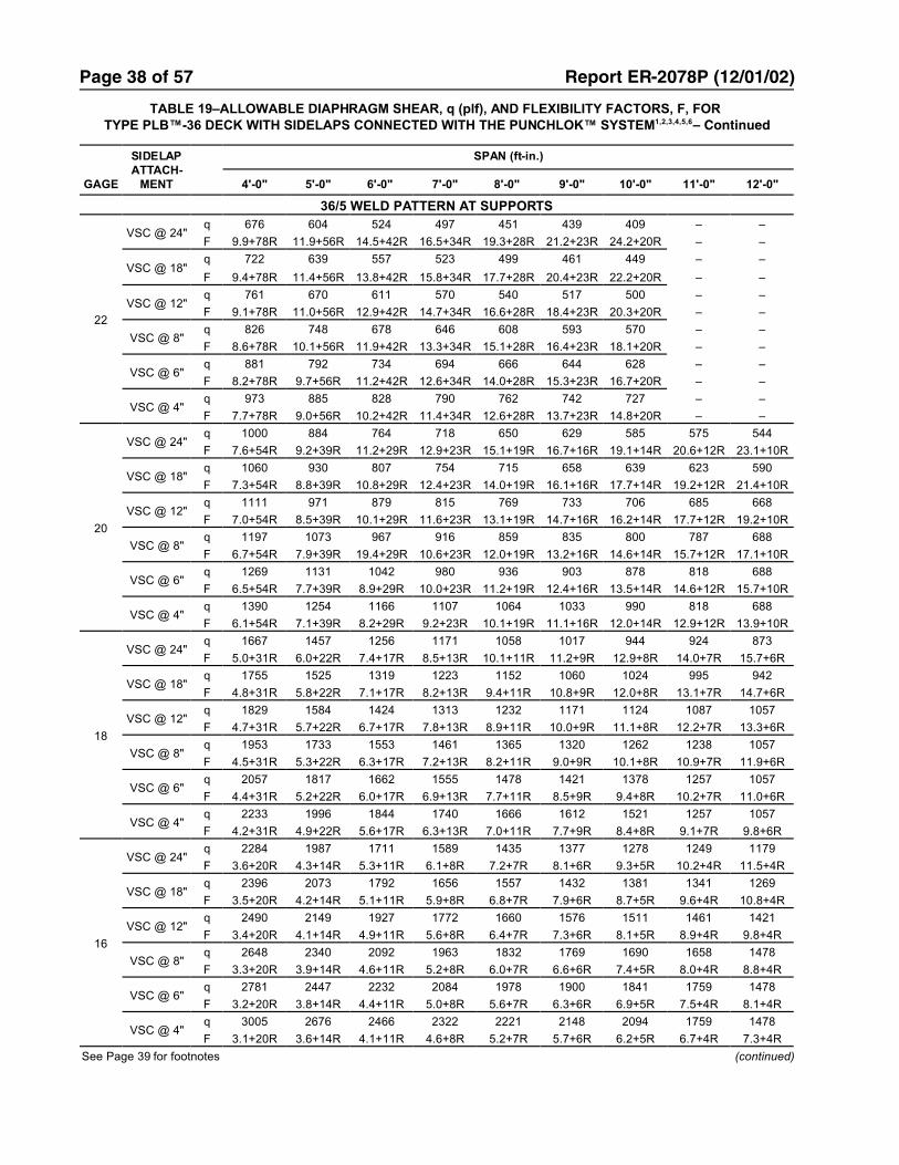
Page 38 of 57 Report ER-2078P (12/01/02)
TABLE 19–ALLOWABLE DIAPHRAGM SHEAR, q (plf), AND FLEXIBILITY FACTORS, F, FOR TYPE PLB™-36 DECK WITH SIDELAPS CONNECTED WITH THE PUNCHLOK™ SYSTEM1,2,3,4,5,6– Continued
GAGE
SIDELAPATTACH-
MENT
SPAN (ft-in.)
4'-0" 5'-0" 6'-0" 7'-0" 8'-0" 9'-0" 10'-0" 11'-0" 12'-0"
36/5 WELD PATTERN AT SUPPORTS
22
VSC @ 24"q 676 604 524 497 451 439 409 – –
F 9.9+78R 11.9+56R 14.5+42R 16.5+34R 19.3+28R 21.2+23R 24.2+20R – –
VSC @ 18"q 722 639 557 523 499 461 449 – –
F 9.4+78R 11.4+56R 13.8+42R 15.8+34R 17.7+28R 20.4+23R 22.2+20R – –
VSC @ 12"q 761 670 611 570 540 517 500 – –
F 9.1+78R 11.0+56R 12.9+42R 14.7+34R 16.6+28R 18.4+23R 20.3+20R – –
VSC @ 8"q 826 748 678 646 608 593 570 – –
F 8.6+78R 10.1+56R 11.9+42R 13.3+34R 15.1+28R 16.4+23R 18.1+20R – –
VSC @ 6"q 881 792 734 694 666 644 628 – –
F 8.2+78R 9.7+56R 11.2+42R 12.6+34R 14.0+28R 15.3+23R 16.7+20R – –
VSC @ 4"q 973 885 828 790 762 742 727 – –
F 7.7+78R 9.0+56R 10.2+42R 11.4+34R 12.6+28R 13.7+23R 14.8+20R – –
20
VSC @ 24"q 1000 884 764 718 650 629 585 575 544
F 7.6+54R 9.2+39R 11.2+29R 12.9+23R 15.1+19R 16.7+16R 19.1+14R 20.6+12R 23.1+10R
VSC @ 18"q 1060 930 807 754 715 658 639 623 590
F 7.3+54R 8.8+39R 10.8+29R 12.4+23R 14.0+19R 16.1+16R 17.7+14R 19.2+12R 21.4+10R
VSC @ 12"q 1111 971 879 815 769 733 706 685 668
F 7.0+54R 8.5+39R 10.1+29R 11.6+23R 13.1+19R 14.7+16R 16.2+14R 17.7+12R 19.2+10R
VSC @ 8"q 1197 1073 967 916 859 835 800 787 688
F 6.7+54R 7.9+39R 19.4+29R 10.6+23R 12.0+19R 13.2+16R 14.6+14R 15.7+12R 17.1+10R
VSC @ 6"q 1269 1131 1042 980 936 903 878 818 688
F 6.5+54R 7.7+39R 8.9+29R 10.0+23R 11.2+19R 12.4+16R 13.5+14R 14.6+12R 15.7+10R
VSC @ 4"q 1390 1254 1166 1107 1064 1033 990 818 688
F 6.1+54R 7.1+39R 8.2+29R 9.2+23R 10.1+19R 11.1+16R 12.0+14R 12.9+12R 13.9+10R
18
VSC @ 24"q 1667 1457 1256 1171 1058 1017 944 924 873
F 5.0+31R 6.0+22R 7.4+17R 8.5+13R 10.1+11R 11.2+9R 12.9+8R 14.0+7R 15.7+6R
VSC @ 18"q 1755 1525 1319 1223 1152 1060 1024 995 942
F 4.8+31R 5.8+22R 7.1+17R 8.2+13R 9.4+11R 10.8+9R 12.0+8R 13.1+7R 14.7+6R
VSC @ 12"q 1829 1584 1424 1313 1232 1171 1124 1087 1057
F 4.7+31R 5.7+22R 6.7+17R 7.8+13R 8.9+11R 10.0+9R 11.1+8R 12.2+7R 13.3+6R
VSC @ 8"q 1953 1733 1553 1461 1365 1320 1262 1238 1057
F 4.5+31R 5.3+22R 6.3+17R 7.2+13R 8.2+11R 9.0+9R 10.1+8R 10.9+7R 11.9+6R
VSC @ 6"q 2057 1817 1662 1555 1478 1421 1378 1257 1057
F 4.4+31R 5.2+22R 6.0+17R 6.9+13R 7.7+11R 8.5+9R 9.4+8R 10.2+7R 11.0+6R
VSC @ 4"q 2233 1996 1844 1740 1666 1612 1521 1257 1057
F 4.2+31R 4.9+22R 5.6+17R 6.3+13R 7.0+11R 7.7+9R 8.4+8R 9.1+7R 9.8+6R
16
VSC @ 24"q 2284 1987 1711 1589 1435 1377 1278 1249 1179
F 3.6+20R 4.3+14R 5.3+11R 6.1+8R 7.2+7R 8.1+6R 9.3+5R 10.2+4R 11.5+4R
VSC @ 18"q 2396 2073 1792 1656 1557 1432 1381 1341 1269
F 3.5+20R 4.2+14R 5.1+11R 5.9+8R 6.8+7R 7.9+6R 8.7+5R 9.6+4R 10.8+4R
VSC @ 12"q 2490 2149 1927 1772 1660 1576 1511 1461 1421
F 3.4+20R 4.1+14R 4.9+11R 5.6+8R 6.4+7R 7.3+6R 8.1+5R 8.9+4R 9.8+4R
VSC @ 8"q 2648 2340 2092 1963 1832 1769 1690 1658 1478
F 3.3+20R 3.9+14R 4.6+11R 5.2+8R 6.0+7R 6.6+6R 7.4+5R 8.0+4R 8.8+4R
VSC @ 6"q 2781 2447 2232 2084 1978 1900 1841 1759 1478
F 3.2+20R 3.8+14R 4.4+11R 5.0+8R 5.6+7R 6.3+6R 6.9+5R 7.5+4R 8.1+4R
VSC @ 4"q 3005 2676 2466 2322 2221 2148 2094 1759 1478
F 3.1+20R 3.6+14R 4.1+11R 4.6+8R 5.2+7R 5.7+6R 6.2+5R 6.7+4R 7.3+4R
See Page 39 for footnotes (continued)

Page 39 of 57 Report ER-2078P (12/01/02)
TABLE 19–ALLOWABLE DIAPHRAGM SHEAR, q (plf), AND FLEXIBILITY FACTORS, F, FOR TYPE PLB™-36 DECK WITH SIDELAPS CONNECTED WITH THE PUNCHLOK™ SYSTEM1,2,3,4,5,6– Continued
GAGE
SIDELAPATTACH-
MENT
SPAN (ft-in.)
4'-0" 5'-0" 6'-0" 7'-0" 8'-0" 9'-0" 10'-0" 11'-0" 12'-0"
36/7 WELD PATTERN AT SUPPORTS
22
VSC @ 24"q 792 707 620 592 544 535 505 – –
F 8.1+22R 7.8+17R 9.2+15R 8.8+12R 10.0+11R 9.5+10R 10.5+9R – –
VSC @ 18"q 836 743 655 621 599 561 554 – –
F 6.5+22R 6.6+17R 7.7+15R 7.6+12R 7.6+11R 8.4+10R 8.2+9R – –
VSC @ 12"q 873 774 713 673 646 628 616 – –
F 5.6+22R 5.9+17R 6.1+15R 6.3+12R 6.4+11R 6.5+10R 6.5+9R – –
VSC @ 8"q 936 853 784 757 724 718 701 – –
F 4.7+22R 4.8+17R 5.0+15R 5.0+12R 5.1+11R 5.1+10R 5.2+9R – –
VSC @ 6"q 988 898 844 811 790 778 753 – –
F 4.3+22R 4.4+17R 4.5+15R 4.5+12R 4.5+11R 4.5+10R 4.6+9R – –
VSC @ 4"q 1077 992 944 917 901 894 753 – –
F 3.8+22R 3.9+17R 3.9+15R 3.9+12R 3.9+11R 3.9+10R 3.9+9R – –
20
VSC @ 24"q 1156 1025 897 852 782 766 722 721 688
F 6.3+15R 6.2+12R 7.3+10R 7.0+9R 8.0+8R 7.6+7R 8.4+6R 8.1+6R 8.8+5R
VSC @ 18"q 1216 1074 944 892 857 802 789 782 688
F 5.1+15R 5.3+12R 6.1+10R 6.1+9R 6.1+8R 6.7+7R 6.7+6R 6.6+6R 7.1+5R
VSC @ 12"q 1266 1117 1023 962 921 893 874 818 688
F 4.5+15R 4.7+12R 4.9+10R 5.1+9R 5.2+8R 5.3+7R 5.3+6R 5.4+6R 5.4+5R
VSC @ 8"q 1351 1224 1120 1078 1028 1016 990 818 688
F 3.8+15R 3.9+12R 4.1+10R 4.1+9R 4.2+8R 4.2+7R 4.3+6R 4.2+6R 4.3+5R
VSC @ 6"q 1422 1284 1202 1150 1119 1099 990 818 688
F 3.5+15R 3.6+12R 3.6+10R 3.7+9R 3.7+8R 3.7+7R 3.8+6R 3.8+6R 3.8+5R
VSC @ 4"q 1542 1413 1338 1295 1270 1223 990 818 688
F 3.1+15R 3.2+12R 3.2+10R 3.2+9R 3.2+8R 3.2+7R 3.2+6R 3.2+6R 3.2+5R
18
VSC @ 24"q 1871 1651 1443 1364 1252 1224 1154 1150 1057
F 4.3+9R 4.3+7R 5.0+6R 4.9+5R 5.5+4R 5.3+4R 5.9+3R 5.7+3R 6.2+3R
VSC @ 18"q 1961 1724 1515 1427 1368 1279 1258 1245 1057
F 3.6+9R 3.7+7R 4.3+6R 4.3+5R 4.3+4R 4.7+4R 4.7+3R 4.7+3R 5.0+3R
VSC @ 12"q 2038 1789 1635 1534 1466 1420 1389 1257 1057
F 3.2+9R 3.3+7R 3.5+6R 3.6+5R 3.7+4R 3.7+4R 3.8+3R 3.8+3R 3.9+3R
VSC @ 8"q 2166 1952 1783 1711 1631 1610 1521 1257 1057
F 2.7+9R 2.8+7R 2.9+6R 2.9+5R 3.0+4R 3.0+4R 3.1+3R 3.1+3R 3.1+3R
VSC @ 6"q 2274 2044 1907 1822 1770 1738 1521 1257 1057
F 2.5+9R 2.6+7R 2.6+6R 2.7+5R 2.7+4R 2.7+4R 2.7+3R 2.7+3R 2.8+3R
VSC @ 4"q 2455 2240 2116 2044 2002 1878 1521 1257 1057
F 2.3+9R 2.3+7R 2.3+6R 2.3+5R 2.4+4R 2.4+4R 2.4+3R 2.4+3R 2.4+3R
16
VSC @ 24"q 2524 2227 1948 1843 1692 1657 1564 1561 1478
F 3.2+5R 3.2+4R 3.7+4R 3.7+3R 4.1+3R 4.0+2R 4.4+2R 4.3+2R 4.7+2R
VSC @ 18"q 2645 2325 2044 1926 1849 1731 1704 1690 1478
F 2.7+5R 2.8+4R 3.2+4R 3.2+3R 3.2+3R 3.6+2R 3.6+2R 3.6+2R 3.8+2R
VSC @ 12"q 2746 2412 2205 2071 1982 1922 1882 1759 1478
F 2.4+5R 2.5+4R 2.6+4R 2.7+3R 2.8+3R 2.8+2R 2.9+2R 2.9+2R 3.0+2R
VSC @ 8"q 2917 2630 2403 2308 2203 2178 2126 1759 1478
F 2.1+5R 2.1+4R 2.2+4R 2.2+3R 2.3+3R 2.3+2R 2.4+2R 2.4+2R 2.4+2R
VSC @ 6"q 3060 2752 2570 2458 2391 2351 2129 1759 1478
F 1.9+5R 2.0+4R 2.0+4R 2.1+3R 2.1+3R 2.1+2R 2.1+2R 2.1+2R 2.1+2R
VSC @ 4"q 3301 3013 2849 2755 2704 2628 2129 1759 1478
F 1.8+5R 1.8+4R 1.8+4R 1.8+3R 1.8+3R 1.9+2R 1.9+2R 1.9+2R 1.9+2R
1 VSC = Verco sidelap connection.2 The dimension from the first and last sidelap connection within
each span is to be no more than one-half of the specified spacing.3 R is the vertical span (Lv) of deck units divided by the length (Ls)
of the deck sheet: R = Lv/Ls.4 The flexibility limitations shown in Table 7 may be used as a guide
in lieu of rational analysis of the anticipated deflections.
5 Interpolation of diaphragm strength between adjacent spans ispermissible. For interpolated lengths, use diaphragm flexibilityfactor for the closest span length.
6 Diaphragm shear values for sidelap fasteners placed at spacingsother than those in the table should be determined based on thenumber of fasteners in each span.

Page 40 of 57 Report ER-2078P (12/01/02)
TABLE 20–ALLOWABLE DIAPHRAGM SHEAR, q (plf), AND FLEXIBILITY FACTORS, F, FOR TYPE HSB™-36 DECKWITH BUTTON PUNCHES (BP) OR 1½" TOP SEAM WELDS (TSW) AT SIDELAPS 1
GAGE
SIDELAPATTACH-
MENT
SPAN (ft-in.)
4'-0" 5'-0" 6'-0" 7'-0" 8'-0" 9'-0" 10'-0" 11'-0" 12'-0"
36/4 WELD PATTERN AT SUPPORTS
22
BP @ 24"q 303 308 289 291 277 262 232 – –
F 4.7+281R 5.7+224R 7.2+187R 8.8+160R 11.0+140R 13.2+125R 16.2+112R – –
BP @ 12"q 363 356 349 343 336 312 284 – –
F 4.4+281R 5.3+224R 6.5+187R 7.9+160R 9.6+140R 11.5+125R 13.8+112R – –
TSW @ 24"q 567 519 434 417 366 359 325 – –
F 38.7+159R 32.6+127R 42.6+106R 37.1+91R 45.3+80R 40.3+71R 47.3+64R – –
TSW @ 18"q 646 577 484 456 435 389 378 – –
F 23.8+159R 22.9+127R 29.6+106R 27.8+91R 26.7+80R 31.6+71R 30.1+64R – –
TSW @ 12"q 718 632 573 531 498 472 451 – –
F 17.0+159R 17.5+127R 17.9+106R 18.2+91R 18.4+80R 18.6+71R 18.8+64R – –
TSW @ 6"q 971 874 807 757 719 689 665 – –
F 8.0+159R 8.1+127R 8.2+106R 8.2+91R 8.2+80R 8.2+71R 8.2+64R – –
20
BP @ 24"q 457 459 434 418 359 327 290 269 244
F 4.3+162R 5.4+130R 7.0+108R 8.7+93R 11.0+81R 13.4+72R 16.5+65R 19.6+59R 23.7+54R
BP @ 12"q 528 517 506 478 421 378 343 314 290
F 4.0+162R 5.0+130R 6.3+108R 7.9+93R 9.7+81R 11.9+72R 14.4+65R 17.2+59R 20.3+54R
TSW @ 24"q 794 710 595 561 493 477 432 424 390
F 30.5+88R 26.4+70R 34.5+59R 30.6+50R 37.5+44R 33.8+39R 39.8+35R 36.4+32R 41.8+29R
TSW @ 18"q 884 777 651 607 573 512 494 478 441
F 19.2+88R 18.8+70R 24.4+59R 23.2+50R 22.5+44R 26.8+39R 25.7+35R 25.0+32R 28.5+29R
TSW @ 12"q 967 840 755 693 646 609 579 554 534
F 13.9+88R 14.5+70R 15.0+59R 15.4+50R 15.8+44R 16.1+39R 16.3+35R 16.5+32R 16.7+29R
TSW @ 6"q 1258 1119 1024 954 902 860 826 798 688
F 6.8+88R 6.9+70R 7.0+59R 7.1+50R 7.1+44R 7.2+39R 7.2+35R 7.3+32R 7.3+29R
18
BP @ 24"q 883 820 671 586 506 458 408 376 342
F 3.8+69R 5.0+55R 6.7+46R 8.6+39R 11.0+34R 13.6+31R 16.9+27R 20.3+25R 24.6+23R
BP @ 12"q 978 891 747 644 567 507 459 420 387
F 3.6+69R 4.8+55R 6.2+46R 7.9+39R 10.0+34R 12.4+31R 15.2+27R 18.4+25R 21.9+23R
TSW @ 24"q 1253 1092 914 845 743 707 639 619 571
F 20.2+35R 18.0+28R 23.6+23R 21.5+20R 26.4+17R 24.3+15R 28.8+14R 26.8+13R 30.8+12R
TSW @ 18"q 1359 1170 980 899 837 748 713 684 631
F 13.1+35R 13.1+28R 17.0+23R 16.6+20R 16.3+17R 19.5+15R 19.0+14R 18.7+13R 21.5+12R
TSW @ 12"q 1455 1244 1102 1000 923 863 815 775 742
F 9.7+35R 10.3+28R 10.8+23R 11.3+20R 11.7+17R 12.0+15R 12.3+14R 12.6+13R 12.9+12R
TSW @ 6"q 1796 1571 1419 1310 1227 1162 1110 1067 1031
F 5.0+35R 5.1+28R 5.3+23R 5.4+20R 5.5+17R 5.6+15R 5.6+14R 5.7+13R 5.8+12R
16
BP @ 24"q 1296 1056 868 755 654 589 526 483 440
F 3.6+35R 4.8+28R 6.5+23R 8.5+20R 11.0+18R 13.7+16R 17.1+14R 20.7+13R 25.1+12R
BP @ 12"q 1399 1124 941 810 712 636 575 525 483
F 3.4+35R 4.6+28R 6.1+23R 8.0+20R 10.2+18R 12.8+16R 15.8+14R 19.2+13R 23.0+12R
TSW @ 24"q 1667 1431 1198 1094 962 907 820 788 726
F 14.2+17R 13.0+13R 17.1+11R 15.8+10R 19.5+8R 18.2+7R 21.6+7R 20.3+6R 23.5+6R
TSW @ 18"q 1781 1516 1270 1153 1065 952 901 860 793
F 9.4+17R 9.6+13R 12.5+11R 12.3+10R 12.3+8R 14.7+7R 14.5+7R 14.4+6R 16.6+6R
TSW @ 12"q 1885 1596 1402 1263 1159 1077 1012 959 915
F 7.1+17R 7.6+13R 8.1+11R 8.5+10R 8.9+8R 9.3+7R 9.6+7R 9.9+6R 10.2+6R
TSW @ 6"q 2252 1950 1746 1600 1490 1404 1335 1279 1233
F 3.8+17R 3.9+13R 4.1+11R 4.2+10R 4.3+8R 4.4+7R 4.5+7R 4.6+6R 4.6+6R
See Page 42 for footnotes (continued)

Page 41 of 57 Report ER-2078P (12/01/02)
TABLE 20–ALLOWABLE DIAPHRAGM SHEAR, q (plf), AND FLEXIBILITY FACTORS, F, FOR TYPE HSB™-36 DECKWITH BUTTON PUNCHES (BP) OR 1½" TOP SEAM WELDS (TSW) AT SIDELAPS 1– Continued
GAGE
SIDELAPATTACH-
MENT
SPAN (ft-in.)
4'-0" 5'-0" 6'-0" 7'-0" 8'-0" 9'-0" 10'-0" 11'-0" 12'-0"
36/5 WELD PATTERN AT SUPPORTS
22
BP @ 24"q 451 445 416 407 351 319 284
F 4.5+157R 5.4+126R 6.9+105R 8.4+90R 10.6+79R 12.8+70R 15.8+63R – –
BP @ 12"q 511 492 476 458 405 364 331 – –
F 4.3+157R 5.2+126R 6.3+105R 7.8+90R 9.5+79R 11.6+70R 13.9+63R – –
TSW @ 24"q 699 627 525 496 437 423 383 – –
F 26.3+77R 22.8+62R 29.6+51R 26.4+44R 32.1+39R 29.1+34R 34.1+31R – –
TSW @ 18"q 780 687 576 538 508 454 439 – –
F 16.8+77R 16.5+62R 21.2+51R 20.2+44R 19.6+39R 23.2+34R 22.3+31R – –
TSW @ 12"q 854 744 669 615 574 541 516 – –
F 12.4+77R 12.9+62R 13.3+51R 13.7+44R 14.0+39R 14.2+34R 14.4+31R – –
TSW @ 6"q 1115 993 910 850 804 768 738 – –
F 6.5+77R 6.6+62R 6.7+51R 6.7+44R 6.8+39R 6.8+34R 6.9+31R – –
20
BP @ 24"q 690 675 590 516 447 405 361 334 304
F 4.0+91R 5.1+73R 6.5+61R 8.2+52R 10.4+45R 12.8+40R 15.9+36R 19.0+33R 23.1+30R
BP @ 12"q 762 733 656 568 501 450 408 374 346
F 3.9+91R 4.9+73R 6.1+61R 7.7+52R 9.5+45R 11.7+40R 14.3+36R 17.2+33R 20.6+30R
TSW @ 24"q 991 872 730 679 598 572 518 504 465
F 20.5+43R 18.2+34R 23.7+28R 21.5+24R 26.2+21R 24.1+19R 28.3+17R 26.3+16R 30.2+14R
TSW @ 18"q 1084 941 788 727 680 608 583 561 518
F 13.4+43R 13.4+34R 17.2+28R 16.6+24R 16.3+21R 19.4+19R 18.8+17R 18.5+16R 21.1+14R
TSW @ 12"q 1169 1006 895 816 756 709 672 641 615
F 10.0+43R 10.6+34R 11.0+28R 11.4+24R 11.8+21R 12.1+19R 12.4+17R 12.6+16R 12.8+14R
TSW @ 6"q 1469 1293 1174 1088 1023 972 931 818 688
F 5.4+43R 5.5+34R 5.6+28R 5.7+24R 5.8+21R 5.9+19R 5.9+17R 6.0+16R 6.0+14R
18
BP @ 24"q 1264 1030 849 738 641 577 516 475 433
F 3.5+39R 4.6+31R 6.1+26R 7.9+22R 10.2+19R 12.7+17R 15.9+15R 19.4+14R 23.6+13R
BP @ 12"q 1353 1089 914 788 694 621 562 514 475
F 3.4+39R 4.5+31R 5.8+26R 7.5+22R 9.5+19R 12.0+17R 14.8+15R 18.0+14R 21.7+13R
TSW @ 24"q 1582 1359 1138 1040 914 862 780 750 691
F 13.4+17R 12.3+13R 16.0+11R 14.9+10R 18.3+8R 17.1+7R 20.2+7R 19.1+6R 22.0+6R
TSW @ 18"q 1690 1440 1206 1096 1012 905 858 818 755
F 9.0+17R 9.2+13R 11.9+11R 11.7+10R 11.7+8R 13.9+7R 13.8+7R 13.7+6R 15.7+6R
TSW @ 12"q 1790 1516 1333 1201 1102 1025 964 914 872
F 6.9+17R 7.4+13R 7.8+11R 8.2+10R 8.6+8R 8.9+7R 9.2+7R 9.5+6R 9.8+6R
TSW @ 6"q 2140 1853 1661 1523 1419 1338 1273 1220 1057
F 3.9+17R 4.1+13R 4.2+11R 4.3+10R 4.4+8R 4.5+7R 4.6+7R 4.7+6R 4.7+6R
16
BP @ 24"q 1656 1343 1110 962 837 751 673 617 563
F 3.2+20R 4.3+16R 5.9+13R 7.7+11R 10.0+10R 12.7+9R 16.0+8R 19.5+7R 23.9+7R
BP @ 12"q 1741 1400 1172 1010 888 793 717 655 603
F 3.1+20R 4.2+16R 5.6+13R 7.4+11R 9.5+10R 12.1+9R 15.1+8R 18.5+7R 22.4+7R
TSW @ 24"q 2115 1794 1502 1358 1194 1117 1011 964 888
F 9.5+8R 8.9+6R 11.6+5R 10.9+5R 13.5+4R 12.8+4R 15.2+3R 14.5+3R 16.7+3R
TSW @ 18"q 2232 1882 1576 1420 1302 1164 1096 1039 959
F 6.5+8R 6.7+6R 8.7+5R 8.7+5R 8.8+4R 10.5+4R 10.5+3R 10.5+3R 12.1+3R
TSW @ 12"q 2339 1964 1713 1534 1400 1296 1212 1145 1088
F 5.1+8R 5.5+6R 5.9+5R 6.2+5R 6.5+4R 6.8+4R 7.1+3R 7.4+3R 7.7+3R
TSW @ 6"q 2716 2329 2070 1884 1745 1638 1552 1482 1424
F 3.0+8R 3.1+6R 3.2+5R 3.4+5R 3.5+4R 3.6+4R 3.6+3R 3.7+3R 3.8+3R
See Page 42 for footnotes (continued)

Page 42 of 57 Report ER-2078P (12/01/02)
TABLE 20–ALLOWABLE DIAPHRAGM SHEAR, q (plf), AND FLEXIBILITY FACTORS, F, FOR TYPE HSB™-36 DECKWITH BUTTON PUNCHES (BP) OR 1½" TOP SEAM WELDS (TSW) AT SIDELAPS 1– Continued
GAGE
SIDELAPATTACH-
MENT
SPAN (ft-in.)
4'-0" 5'-0" 6'-0" 7'-0" 8'-0" 9'-0" 10'-0" 11'-0" 12'-0"
36/7 WELD PATTERN AT SUPPORTS
22
BP @ 24"q 623 598 522 458 397 360 322 – –
F 4.1+70R 4.9+56R 6.1+47R 7.5+40R 9.3+35R 11.3+31R 13.9+28R – –
BP @ 12"q 683 646 579 502 445 400 364 – –
F 4.0+70R 4.8+56R 5.8+47R 7.0+40R 8.6+35R 10.5+31R 12.7+28R – –
TSW @ 24"q 731 720 595 600 521 529 474 – –
F 12.2+6R 11.8+5R 16.0+4R 15.3+4R 19.4+3R 18.5+3R 22.6+3R – –
TSW @ 18"q 907 851 704 689 667 597 578 – –
F 8.4+6R 8.9+5R 11.8+4R 12.0+4R 12.3+3R 15.0+3R 15.1+3R – –
TSW @ 12"q 1072 972 877 808 756 715 682 – –
F 6.6+6R 7.3+5R 7.9+4R 8.5+4R 9.1+3R 9.6+3R 10.1+3R – –
TSW @ 6"q 1464 1310 1204 1127 1068 929 753 – –
F 4.2+6R 4.5+5R 4.7+4R 4.8+4R 5.0+3R 5.2+3R 5.3+3R – –
20
BP @ 24"q 962 804 663 578 502 454 406 375 342
F 3.7+41R 4.5+32R 5.7+27R 7.1+23R 9.0+20R 11.1+18R 13.8+16R 16.7+15R 20.4+14R
BP @ 12"q 1034 854 719 622 549 493 448 411 380
F 3.6+41R 4.4+32R 5.4+27R 6.8+23R 8.5+20R 10.4+18R 12.8+16R 15.5+15R 18.6+14R
TSW @ 24"q 999 969 800 796 691 695 621 629 573
F 9.8+4R 9.5+3R 13.0+3R 12.5+2R 16.0+2R 15.4+2R 18.8+2R 18.2+2R 21.5+1R
TSW @ 18"q 1224 1134 937 908 882 779 769 757 688
F 6.8+4R 7.3+3R 9.6+3R 9.9+2R 10.2+2R 12.5+2R 12.7+2R 12.9+2R 15.1+1R
TSW @ 12"q 1431 1292 1189 1091 1016 958 912 818 688
F 5.4+4R 6.0+3R 6.6+3R 7.1+2R 7.6+2R 8.1+2R 8.5+2R 9.0+2R 9.4+1R
TSW @ 6"q 1965 1745 1596 1488 1406 1223 990 818 688
F 3.5+4R 3.7+3R 3.9+3R 4.1+2R 4.2+2R 4.4+2R 4.5+2R 4.6+2R 4.8+1R
18
BP @ 24"q 1405 1140 943 818 712 640 574 527 482
F 3.1+17R 4.0+14R 5.2+11R 6.7+10R 8.7+9R 10.9+8R 13.7+7R 16.8+6R 20.6+6R
BP @ 12"q 1475 1188 996 860 757 678 614 562 518
F 3.0+17R 3.9+14R 5.0+11R 6.5+10R 8.3+9R 10.4+8R 12.9+7R 15.9+6R 19.2+6R
TSW @ 24"q 1571 1495 1229 1206 1044 1039 926 928 844
F 6.8+2R 6.7+2R 9.1+1R 9.0+1R 11.4+1R 11.2+1R 13.7+1R 13.4+1R 15.9+1R
TSW @ 18"q 1895 1730 1424 1363 1312 1155 1131 1110 1010
F 4.8+2R 5.2+2R 6.9+1R 7.1+1R 7.4+1R 9.1+1R 9.4+1R 9.6+1R 11.3+1R
TSW @ 12"q 2191 1952 1767 1612 1495 1405 1332 1257 1057
F 3.9+2R 4.3+2R 4.8+1R 5.2+1R 5.6+1R 6.0+1R 6.4+1R 6.7+1R 7.1+1R
TSW @ 6"q 2878 2535 2304 2139 2014 1878 1521 1257 1057
F 2.6+2R 2.8+2R 2.9+1R 3.0+1R 3.2+1R 3.3+1R 3.4+1R 3.5+1R 3.6+1R
16
BP @ 24"q 1825 1475 1223 1058 922 826 741 679 621
F 2.8+9R 3.7+7R 4.9+6R 6.5+5R 8.5+4R 10.8+4R 13.6+4R 16.8+3R 20.6+3R
BP @ 12"q 1891 1521 1273 1097 964 862 779 712 656
F 2.7+9R 3.6+7R 4.8+6R 6.3+5R 8.1+4R 10.4+4R 13.0+4R 16.1+3R 19.6+3R
TSW @ 24"q 2171 2043 1675 1630 1406 1390 1236 1233 1119
F 5.0+1R 5.1+1R 6.9+1R 6.8+1R 8.7+1R 8.6+1R 10.6+1R 10.4 12.4
TSW @ 18"q 2599 2350 1929 1833 1734 1540 1487 1431 1324
F 3.6+1R 4.0+1R 5.2+1R 5.5+1R 5.7+1R 7.1+1R 7.3+1R 7.5 8.9
TSW @ 12"q 2985 2556 2270 2065 1912 1793 1699 1622 1478
F 3.0+1R 3.3+1R 3.7+1R 4.0+1R 4.3+1R 4.7+1R 5.0+1R 5.3 5.6
TSW @ 6"q 3664 3215 2914 2698 2538 2413 2129 1759 1478
F 2.0+1R 2.2+1R 2.3+1R 2.4+1R 2.5+1R 2.6+1R 2.7+1R 2.8 2.9
1 Footnotes 2–6 of Table 19 apply to this table.
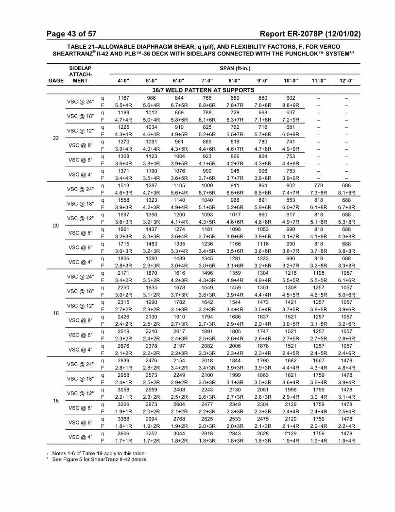
Page 43 of 57 Report ER-2078P (12/01/02)
TABLE 21–ALLOWABLE DIAPHRAGM SHEAR, q (plf), AND FLEXIBILITY FACTORS, F, FOR VERCOSHEARTRANZ
® II-42 AND PLB™-36 DECK WITH SIDELAPS CONNECTED WITH THE PUNCHLOK™ SYSTEM1,2
GAGE
SIDELAPATTACH-
MENT
SPAN (ft-in.)
4'-0" 5'-0" 6'-0" 7'-0" 8'-0" 9'-0" 10'-0" 11'-0" 12'-0"
36/7 WELD PATTERN AT SUPPORTS
22
VSC @ 24"q 1167 986 844 766 689 650 602 – –
F 5.5+4R 5.6+4R 6.7+5R 6.8+6R 7.8+7R 7.8+8R 8.8+9R – –
VSC @ 18"q 1199 1012 869 788 729 668 637 – –
F 4.7+4R 5.0+4R 5.8+5R 6.1+6R 6.3+7R 7.1+8R 7.2+9R – –
VSC @ 12"q 1225 1034 910 825 762 716 681 – –
F 4.3+4R 4.6+4R 4.9+5R 5.2+6R 5.5+7R 5.7+8R 6.0+9R – –
VSC @ 8"q 1270 1091 961 885 819 780 741 – –
F 3.9+4R 4.0+4R 4.3+5R 4.4+6R 4.6+7R 4.7+8R 4.9+9R – –
VSC @ 6"q 1308 1123 1004 923 866 824 753 – –
F 3.6+4R 3.8+4R 3.9+5R 4.1+6R 4.2+7R 4.3+8R 4.4+9R – –
VSC @ 4"q 1371 1190 1076 999 945 906 753 – –
F 3.4+4R 3.5+4R 3.6+5R 3.7+6R 3.7+7R 3.8+8R 3.9+9R – –
20
VSC @ 24"q 1513 1287 1105 1009 911 864 802 778 688
F 4.6+3R 4.7+3R 5.6+4R 5.7+5R 6.5+6R 6.5+6R 7.4+7R 7.3+8R 8.1+8R
VSC @ 18"q 1558 1323 1140 1040 968 891 853 818 688
F 3.9+3R 4.2+3R 4.9+4R 5.1+5R 5.2+6R 5.9+6R 6.0+7R 6.1+8R 6.7+8R
VSC @ 12"q 1597 1356 1200 1093 1017 960 917 818 688
F 3.6+3R 3.9+3R 4.1+4R 4.3+5R 4.6+6R 4.8+6R 4.9+7R 5.1+8R 5.3+8R
VSC @ 8"q 1661 1437 1274 1181 1098 1053 990 818 688
F 3.2+3R 3.3+3R 3.6+4R 3.7+5R 3.9+6R 3.9+6R 4.1+7R 4.1+8R 4.3+8R
VSC @ 6"q 1715 1483 1335 1236 1166 1116 990 818 688
F 3.0+3R 3.2+3R 3.3+4R 3.4+5R 3.5+6R 3.6+6R 3.6+7R 3.7+8R 3.8+8R
VSC @ 4"q 1806 1580 1439 1345 1281 1223 990 818 688
F 2.8+3R 2.9+3R 3.0+4R 3.0+5R 3.1+6R 3.2+6R 3.2+7R 3.2+8R 3.3+8R
18
VSC @ 24"q 2171 1870 1616 1496 1359 1304 1218 1195 1057
F 3.4+2R 3.5+2R 4.2+3R 4.3+3R 4.9+4R 4.9+4R 5.5+5R 5.5+5R 6.1+6R
VSC @ 18"q 2250 1934 1678 1549 1459 1351 1308 1257 1057
F 3.0+2R 3.1+2R 3.7+3R 3.8+3R 3.9+4R 4.4+4R 4.5+5R 4.6+5R 5.0+6R
VSC @ 12"q 2315 1990 1782 1642 1544 1473 1421 1257 1057
F 2.7+2R 2.9+2R 3.1+3R 3.2+3R 3.4+4R 3.5+4R 3.7+5R 3.8+5R 3.9+6R
VSC @ 8"q 2426 2130 1910 1794 1686 1637 1521 1257 1057
F 2.4+2R 2.5+2R 2.7+3R 2.7+3R 2.9+4R 2.9+4R 3.0+5R 3.1+5R 3.2+6R
VSC @ 6"q 2519 2210 2017 1891 1805 1747 1521 1257 1057
F 2.3+2R 2.4+2R 2.4+3R 2.5+3R 2.6+4R 2.6+4R 2.7+5R 2.7+5R 2.8+6R
VSC @ 4"q 2676 2378 2197 2082 2006 1878 1521 1257 1057
F 2.1+2R 2.2+2R 2.2+3R 2.3+3R 2.3+4R 2.3+4R 2.4+5R 2.4+5R 2.4+6R
16
VSC @ 24"q 2839 2476 2154 2018 1844 1790 1682 1667 1478
F 2.8+1R 2.8+2R 3.4+2R 3.4+3R 3.9+3R 3.9+3R 4.4+4R 4.3+4R 4.8+4R
VSC @ 18"q 2958 2573 2249 2100 1999 1863 1821 1759 1478
F 2.4+1R 2.5+2R 2.9+2R 3.0+3R 3.1+3R 3.5+3R 3.6+4R 3.6+4R 3.9+4R
VSC @ 12"q 3058 2659 2408 2243 2130 2051 1996 1759 1478
F 2.2+1R 2.3+2R 2.5+2R 2.6+3R 2.7+3R 2.8+3R 2.9+4R 3.0+4R 3.1+4R
VSC @ 8"q 3226 2873 2604 2477 2349 2304 2129 1759 1478
F 1.9+1R 2.0+2R 2.1+2R 2.2+3R 2.3+3R 2.3+3R 2.4+4R 2.4+4R 2.5+4R
VSC @ 6"q 3368 2994 2768 2625 2533 2475 2129 1759 1478
F 1.8+1R 1.9+2R 1.9+2R 2.0+3R 2.0+3R 2.1+3R 2.1+4R 2.2+4R 2.2+4R
VSC @ 4"q 3606 3252 3044 2918 2843 2628 2129 1759 1478
F 1.7+1R 1.7+2R 1.8+2R 1.8+3R 1.8+3R 1.8+3R 1.9+4R 1.9+4R 1.9+4R
1 Notes 1-6 of Table 19 apply to this table. 2 See Figure 5 for ShearTranz II-42 details.

Page 44 of 57 Report ER-2078P (12/01/02)
FIGURE 5–DETAILS FOR SHEARTRANZ® II FOR PLB™-36 & SHEARTRANZ® II FOR HSB™-36 DECK

Page 45 of 57 Report ER-2078P
TABLE 22–ALLOWABLE DIAPHRAGM SHEAR, q (plf), AND FLEXIBILITY FACTORS, F, FOR VERCOSHEARTRANZ
® II AND HSB™-36 WITH BUTTON PUNCHES (BP) or
1½ INCH TOP SEAM WELDS (TSW) AT SIDELAPS 1,2
GAGE
SIDELAPATTACH -
MENT
SPAN (ft-in.)
5'-0" 5'-6" 6'-0" 6'-6" 7'-0" 7'-6" 8'-0" 8'-6" 9'-0" 9'-6" 10'-0"
36/7 WELD PATTERN AT SUPPORTS
22
BP @ 24”q 953 880 819 767 724 686 653 624 598 576 555
F 7.8 8.4 8.9 9.5 10.0 10.5 11.1 11.6 12.2 12.7 13.3
BP @ 18”q 997 924 863 813 769 732 699 671 646 623 603
F 7.6 8.1 8.6 9.1 9.6 10.1 10.5 11.0 11.5 12.0 12.4
BP @ 12”q 1084 1012 953 903 860 824 792 765 740 719 700
F 7.2 7.6 8.1 8.5 8.9 9.2 9.6 10.0 10.4 10.7 11.1
TSW @ 24”q 865 808 759 719 684 654 628 605 585 567 551
F 5.1 5.3 5.5 5.7 5.9 6.1 6.2 6.4 6.5 6.7 6.8
TSW @ 18”q 961 904 855 815 780 750 724 701 681 663 647
F 4.9 5.1 5.2 5.4 5.5 5.6 5.8 5.9 6.0 6.1 6.2
TSW @ 12”q 1153 1095 1047 1007 972 942 916 893 873 855 839
F 4.6 4.7 4.8 4.9 5.0 5.1 5.1 5.2 5.3 5.4 5.5
20
BP @ 24”q 1120 1032 959 898 845 799 760 725 694 667 643
F 6.1 6.5 6.9 7.3 7.7 8.2 8.6 9.1 9.5 9.9 10.4
BP @ 18”q 1165 1078 1005 944 892 847 808 773 743 716 692
F 5.9 6.3 6.7 7.1 7.5 7.8 8.2 8.6 9.0 9.4 9.8
BP @ 12”q 1255 1168 1097 1037 985 942 903 870 841 815 792
F 5.7 6.0 6.3 6.6 7.0 7.3 7.6 7.9 8.2 8.6 8.9
TSW @ 24”q 1309 1218 1143 1079 1025 978 938 902 870 842 817
F 4.1 4.2 4.4 4.5 4.6 4.8 4.9 5.0 5.2 5.3 5.4
TSW @ 18”q 1447 1356 1281 1218 1163 1117 1076 1040 1008 980 955
F 3.9 4.0 4.1 4.3 4.4 4.5 4.6 4.7 4.8 4.9 5.0
TSW @ 12”q 1724 1633 1558 1494 1440 1393 1352 1317 1285 1209 1091
F 3.6 3.7 3.8 3.9 4.0 4.0 4.1 4.2 4.3 4.3 4.4
18
BP @ 24”q 1453 1335 1238 1156 1085 1025 972 926 885 848 815
F 4.1 4.4 4.6 4.9 5.2 5.5 5.8 6.2 6.5 6.8 7.1
BP @ 18”q 1499 1382 1286 1204 1135 1075 1022 977 936 900 868
F 4.0 4.3 4.5 4.8 5.1 5.4 5.6 5.9 6.2 6.5 6.8
BP @ 12”q 1592 1477 1381 1301 1233 1174 1123 1079 1040 1005 974
F 3.9 4.1 4.3 4.6 4.8 5.1 5.3 5.5 5.8 6.0 6.2
TSW @ 24”q 1862 1751 1659 1583 1518 1463 1416 1375 1339 1308 1281
F 2.8 2.9 3.0 3.1 3.2 3.3 3.4 3.5 3.6 3.7 3.8
TSW @ 18”q 2045 1936 1847 1773 1711 1659 1614 1576 1543 1514 1453
F 2.7 2.8 2.9 3.0 3.1 3.1 3.2 3.3 3.4 3.4 3.5
TSW @ 12”q 2411 2307 2224 2155 2098 2051 2011 1978 1794 1610 1453
F 2.6 2.7 2.7 2.8 2.8 2.9 2.9 3.0 3.0 3.1 3.1
16
BP @ 24”q 1787 1640 1518 1415 1328 1252 1185 1127 1076 1030 989
F 3.0 3.2 3.4 3.7 3.9 4.1 4.4 4.6 4.8 5.1 5.3
BP @ 18”q 1835 1689 1568 1466 1379 1304 1238 1181 1130 1085 1045
F 3.0 3.2 3.4 3.6 3.8 4.0 4.2 4.4 4.7 4.9 5.1
BP @ 12”q 1932 1787 1668 1567 1482 1408 1344 1288 1239 1195 1156
F 2.9 3.1 3.3 3.4 3.6 3.8 4.0 4.2 4.4 4.6 4.8
TSW @ 24”q 2279 2140 2026 1932 1852 1784 1725 1675 1631 1592 1559
F 2.2 2.2 2.3 2.4 2.5 2.5 2.6 2.7 2.8 2.8 2.9
TSW @ 18”q 2491 2356 2246 2154 2078 2013 1958 1911 1870 1835 1803
F 2.1 2.2 2.2 2.3 2.3 2.4 2.5 2.5 2.6 2.6 2.7
TSW @ 12”q 2915 2787 2684 2600 2530 2472 2424 2383 2226 1998 1803
F 2.0 2.0 2.1 2.1 2.2 2.2 2.3 2.3 2.3 2.4 2.4
1 See Figure 5 for ShearTranz II details.2 The flexibility limitations shown in Table 7 may be used in lieu of a rational analysis of the anticipated deflections.
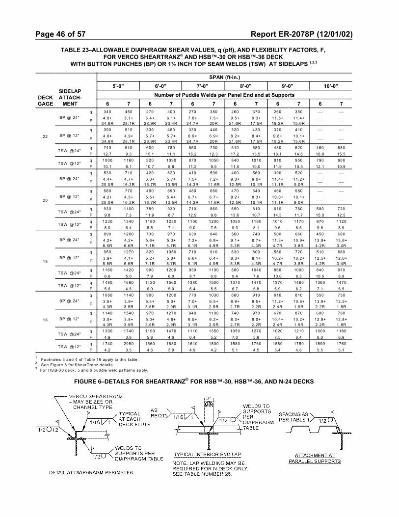
Page 46 of 57 Report ER-2078P (12/01/02)
TABLE 23–ALLOWABLE DIAPHRAGM SHEAR VALUES, q (plf), AND FLEXIBILITY FACTORS, F, FOR VERCO SHEARTRANZ® AND HSB™-30 OR HSB™-36 DECK
WITH BUTTON PUNCHES (BP) OR 1½ INCH TOP SEAM WELDS (TSW) AT SIDELAPS 1,2,3
DECKGAGE
SIDELAPATTACH-
MENT
SPAN (ft-in.)
5'-0" 6'-0" 7'-0" 8'-0" 9'-0" 10'-0"
Number of Puddle Welds per Panel End and at Supports
6 7 6 7 6 7 6 7 6 7 6 7
22
BP @ 24"
q 340 450 270 400 270 380 260 370 260 350 –– ––
F4.8+
34.6R
5.1+
28.1R
6.4+
28.9R
6.1+
23.4R
7.8+
24.7R
7.5+
20R
9.5+
21.6R
9.3+
17.5R
11.5+
19.2R
11.4+
15.6R–– ––
BP @ 12"
q 390 510 330 460 330 440 320 430 320 410 –– ––
F4.6+
34.6R
4.9+
28.1R
5.7+
28.9R
5.7+
23.4R
6.9+
24.7R
6.9+
20R
8.2+
21.6R
8.4+
17.5R
9.8+
19.2R
10.1+
15.6R–– ––
TSW @ 24" q 740 940 600 780 550 730 510 680 480 620 460 580
F 12.7 9.3 15.1 11.1 16.2 12.3 17.2 13.5 18.1 14.6 18.8 15.5
TSW @ 12" q 1000 1160 920 1090 870 1050 840 1010 810 950 790 900
F 10.1 8.1 10.7 8.8 11.2 9.5 11.5 10.0 11.9 10.5 12.1 10.9
20
BP @ 24"
q 530 710 420 620 410 590 400 560 390 520 –– ––
F4.4+
20.0R
4.7+
16.2R
6.0+
16.7R
5.7+
13.5R
7.5+
14.3R
7.2+
11.6R
9.3+
12.5R
9.0+
10.1R
11.4+
11.1R
11.2+
9.0R–– ––
BP @ 12"
q 580 770 490 690 480 660 470 640 460 580 –– ––
F4.2+
20.0R
4.5+
16.2R
5.5+
16.7R
5.4+
13.5R
6.7+
14.3R
6.7+
11.6R
8.2+
12.5R
8.3+
10.1R
10.0+
11.1R
10.1+
9.0R–– ––
TSW @ 24" q 930 1100 780 930 710 860 650 810 610 780 580 720
F 9.8 7.3 11.9 8.7 12.9 9.8 13.6 10.7 14.3 11.7 15.0 12.5
TSW @ 12" q 1230 1340 1180 1250 1100 1200 1050 1180 1010 1170 970 1120
F 8.0 6.4 8.6 7.1 9.0 7.6 9.3 8.1 9.6 8.5 9.8 8.9
18
BP @ 24"
q 890 1200 730 970 630 840 560 740 500 660 450 600
F4.2+
8.5R
4.2+
6.6R
5.6+
7.1R
5.3+
5.7R
7.2+
6.1R
6.8+
4.9R
9.1+
5.3R
8.7+
4.3R
11.3+
4.7R
10.9+
3.8R
13.9+
4.2R
13.6+
3.4R
BP @ 12"
q 950 1270 820 1050 710 910 630 800 560 720 510 660
F3.9+
8.5R
4.1+
6.6R
5.2+
7.1R
5.0+
5.7R
6.6+
6.1R
6.4+
4.9R
8.3+
5.3R
8.1+
4.3R
10.2+
4.7R
10.2+
3.8R
12.5+
4.2R
12.6+
3.4R
TSW @ 24" q 1160 1420 990 1200 930 1100 880 1040 860 1000 840 970
F 6.6 5.0 7.9 6.0 8.7 6.8 9.4 7.6 10.0 8.3 10.5 8.9
TSW @ 12" q 1480 1690 1420 1560 1380 1500 1370 1470 1370 1460 1360 1470
F 5.6 4.5 6.0 5.0 6.4 5.5 6.7 5.8 6.9 6.2 7.1 6.5
16
BP @ 24"
q 1080 1140 900 1200 770 1030 680 910 610 810 550 730
F3.6+
4.3R
3.9+
3.5R
5.4+
3.6R
5.0+
2.9R
7.0+
3.1R
6.5+
2.5R
8.9+
2.7R
8.5+
2.2R
11.2+
2.4R
10.8+
1.9R
13.9+
2.2R
13.5+
1.8R
BP @ 12"
q 1140 1540 970 1270 840 1100 740 970 670 870 600 780
F3.5+
4.3R
3.8+
3.5R
5.0+
3.6R
4.8+
2.9R
6.5+
3.1R
6.2+
2.5R
8.3+
2.7R
8.0+
2.2R
10.4+
2.4R
10.2+
1.9R
12.8+
2.2R
12.8+
1.8R
TSW @ 24" q 1390 1740 1190 1470 1110 1350 1050 1270 1020 1210 1000 1180
F 4.9 3.8 5.8 4.6 6.4 5.2 7.0 5.8 7.5 6.4 8.0 6.9
TSW @ 12" q 1740 2050 1660 1880 1610 1800 1580 1760 1580 1750 1590 1760
F 4.2 3.5 4.6 3.9 4.9 4.2 5.1 4.5 5.4 4.8 5.5 5.1
1Footnotes 3 and 4 of Table 19 apply to this table.
2See Figure 6 for ShearTranz details.
3 For HS B-3 0 de ck , 5 an d 6 p uddle we ld pa tterns ap ply.
FIGURE 6–DETAILS FOR SHEARTRANZ® FOR HSB™-30, HSB™-36, AND N-24 DECKS
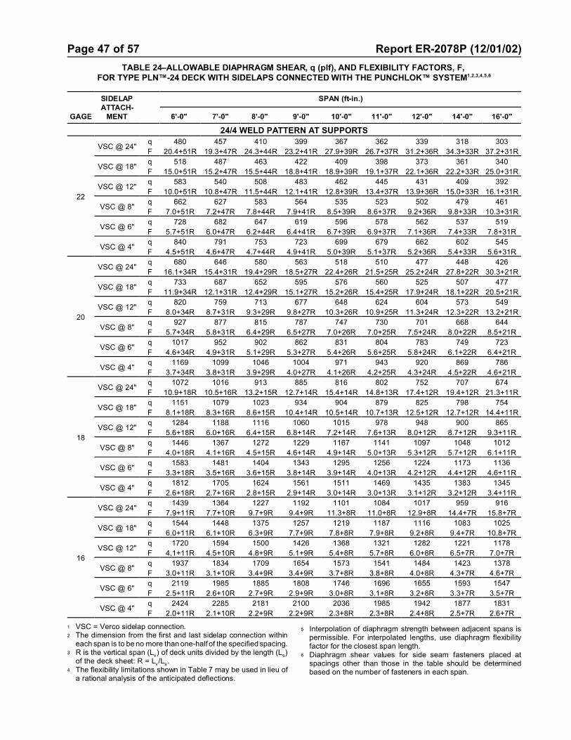
Page 47 of 57 Report ER-2078P (12/01/02)
TABLE 24–ALLOWABLE DIAPHRAGM SHEAR, q (plf), AND FLEXIBILITY FACTORS, F, FOR TYPE PLN™-24 DECK WITH SIDELAPS CONNECTED WITH THE PUNCHLOK™ SYSTEM1,2,3,4,5,6
GAGE
SIDELAPATTACH-
MENT
SPAN (ft-in.)
6'-0" 7'-0" 8'-0" 9'-0" 10'-0" 11'-0" 12'-0" 14'-0" 16'-0"
24/4 WELD PATTERN AT SUPPORTS
22
VSC @ 24"q 480 457 410 399 367 362 339 318 303
F 20.4+51R 19.3+47R 24.3+44R 23.2+41R 27.9+39R 26.7+37R 31.2+36R 34.3+33R 37.2+31R
VSC @ 18"q 518 487 463 422 409 398 373 361 340
F 15.0+51R 15.2+47R 15.5+44R 18.8+41R 18.9+39R 19.1+37R 22.1+36R 22.2+33R 25.0+31R
VSC @ 12"q 583 540 508 483 462 445 431 409 392
F 10.0+51R 10.8+47R 11.5+44R 12.1+41R 12.8+39R 13.4+37R 13.9+36R 15.0+33R 16.1+31R
VSC @ 8"q 662 627 583 564 535 523 502 479 461
F 7.0+51R 7.2+47R 7.8+44R 7.9+41R 8.5+39R 8.6+37R 9.2+36R 9.8+33R 10.3+31R
VSC @ 6"q 728 682 647 619 596 578 562 537 519
F 5.7+51R 6.0+47R 6.2+44R 6.4+41R 6.7+39R 6.9+37R 7.1+36R 7.4+33R 7.8+31R
VSC @ 4"q 840 791 753 723 699 679 662 602 545
F 4.5+51R 4.6+47R 4.7+44R 4.9+41R 5.0+39R 5.1+37R 5.2+36R 5.4+33R 5.6+31R
20
VSC @ 24"q 680 646 580 563 518 510 477 448 426
F 16.1+34R 15.4+31R 19.4+29R 18.5+27R 22.4+26R 21.5+25R 25.2+24R 27.8+22R 30.3+21R
VSC @ 18"q 733 687 652 595 576 560 525 507 477
F 11.9+34R 12.1+31R 12.4+29R 15.1+27R 15.2+26R 15.4+25R 17.9+24R 18.1+22R 20.5+21R
VSC @ 12"q 820 759 713 677 648 624 604 573 549
F 8.0+34R 8.7+31R 9.3+29R 9.8+27R 10.3+26R 10.9+25R 11.3+24R 12.3+22R 13.2+21R
VSC @ 8"q 927 877 815 787 747 730 701 668 644
F 5.7+34R 5.8+31R 6.4+29R 6.5+27R 7.0+26R 7.0+25R 7.5+24R 8.0+22R 8.5+21R
VSC @ 6"q 1017 952 902 862 831 804 783 749 723
F 4.6+34R 4.9+31R 5.1+29R 5.3+27R 5.4+26R 5.6+25R 5.8+24R 6.1+22R 6.4+21R
VSC @ 4"q 1169 1099 1046 1004 971 943 920 869 786
F 3.7+34R 3.8+31R 3.9+29R 4.0+27R 4.1+26R 4.2+25R 4.3+24R 4.5+22R 4.6+21R
18
VSC @ 24"q 1072 1016 913 885 816 802 752 707 674
F 10.9+18R 10.5+16R 13.2+15R 12.7+14R 15.4+14R 14.8+13R 17.4+12R 19.4+12R 21.3+11R
VSC @ 18"q 1151 1079 1023 934 904 879 825 798 754
F 8.1+18R 8.3+16R 8.6+15R 10.4+14R 10.5+14R 10.7+13R 12.5+12R 12.7+12R 14.4+11R
VSC @ 12"q 1284 1188 1116 1060 1015 978 948 900 865
F 5.6+18R 6.0+16R 6.4+15R 6.8+14R 7.2+14R 7.6+13R 8.0+12R 8.7+12R 9.3+11R
VSC @ 8"q 1446 1367 1272 1229 1167 1141 1097 1048 1012
F 4.0+18R 4.1+16R 4.5+15R 4.6+14R 4.9+14R 5.0+13R 5.3+12R 5.7+12R 6.1+11R
VSC @ 6"q 1583 1481 1404 1343 1295 1256 1224 1173 1136
F 3.3+18R 3.5+16R 3.6+15R 3.8+14R 3.9+14R 4.0+13R 4.2+12R 4.4+12R 4.6+11R
VSC @ 4"q 1812 1705 1624 1561 1511 1469 1435 1383 1345
F 2.6+18R 2.7+16R 2.8+15R 2.9+14R 3.0+14R 3.0+13R 3.1+12R 3.2+12R 3.4+11R
16
VSC @ 24"q 1439 1364 1227 1192 1101 1084 1017 959 916
F 7.9+11R 7.7+10R 9.7+9R 9.4+9R 11.3+8R 11.0+8R 12.9+8R 14.4+7R 15.8+7R
VSC @ 18"q 1544 1448 1375 1257 1219 1187 1116 1083 1025
F 6.0+11R 6.1+10R 6.3+9R 7.7+9R 7.8+8R 7.9+8R 9.2+8R 9.4+7R 10.8+7R
VSC @ 12"q 1720 1594 1500 1426 1368 1321 1282 1221 1178
F 4.1+11R 4.5+10R 4.8+9R 5.1+9R 5.4+8R 5.7+8R 6.0+8R 6.5+7R 7.0+7R
VSC @ 8"q 1937 1834 1709 1654 1573 1541 1484 1423 1378
F 3.0+11R 3.1+10R 3.4+9R 3.4+9R 3.7+8R 3.8+8R 4.0+8R 4.3+7R 4.6+7R
VSC @ 6"q 2119 1985 1885 1808 1746 1696 1655 1593 1547
F 2.5+11R 2.6+10R 2.7+9R 2.9+9R 3.0+8R 3.1+8R 3.2+8R 3.3+7R 3.5+7R
VSC @ 4"q 2424 2285 2181 2100 2036 1985 1942 1877 1831
F 2.0+11R 2.1+10R 2.2+9R 2.2+9R 2.3+8R 2.3+8R 2.4+8R 2.5+7R 2.6+7R
1 VSC = Verco sidelap connection.2 The dimension from the first and last sidelap connection within
each span is to be no more than one-half of the specified spacing.3 R is the vertical span (Lv) of deck units divided by the length (Ls)
of the deck sheet: R = Lv/Ls.4 The flexibility limitations shown in Table 7 may be used in lieu of
a rational analysis of the anticipated deflections.
5 Interpolation of diaphragm strength between adjacent spans ispermissible. For interpolated lengths, use diaphragm flexibilityfactor for the closest span length.
6 Diaphragm shear values for side seam fasteners placed atspacings other than those in the table should be determinedbased on the number of fasteners in each span.

Page 48 of 57 Report ER-2078P (12/01/02)
TABLE 25–ALLOWABLE DIAPHRAGM SHEAR, q (plf), AND FLEXIBILITY FACTORS, F, FOR TYPE N-24 DECK WITH BUTTON PUNCHES (BP) OR 1½" TOP SEAM WELDS (TSW) AT SIDELAPS 1
GAGE
SIDELAPATTACH-
MENT
SPAN (ft-in.)
6'-0" 7'-0" 8'-0" 9'-0" 10'-0" 11'-0" 12'-0" 14'-0" 16'-0"
24/4 WELD PATTERN AT SUPPORTS
22
BP @ 24" q 234 216 189 180 163 158 145 130 119
F 21.3+166R 23.3+143R 26.7+125R 28.4+111R 31.8+100R 33.2+91R 36.6+83R 41.1+71R 45.4+62R
BP @ 12" q 285 260 241 227 216 207 198 184 173
F 18.0+166R 19.8+143R 21.5+125R 23.1+111R 24.6+100R 26.1+91R 27.4+83R 29.9+71R 32.1+62R
TSW @ 24"q 234 231 201 202 181 183 167 158 151
F 15.5+166R 13.9+143R 14.1+125R 12.9+111R 13.1+100R 12.1+91R 12.2+83R 11.5+71R 11.0+62R
TSW @ 12" q 343 324 309 298 289 282 276 267 260
F 11.4+166R 10.7+143R 10.1+125R 9.6+111R 9.2+100R 8.8+91R 8.5+83R 8.0+71R 7.5+62R
20
BP @ 24" q 355 323 283 266 240 231 212 189 171
F 16.3+96R 18.2+82R 20.9+72R 22.5+64R 25.3+58R 26.8+52R 29.6+48R 33.8+41R 37.8+36R
BP @ 12" q 415 374 344 321 303 289 277 253 235
F 14.3+96R 16.0+82R 17.6+72R 19.1+64R 20.5+58R 21.9+52R 23.2+48R 25.7+41R 28.1+36R
TSW @ 24"q 384 371 322 320 286 287 262 245 232
F 12.3+96R 11.3+82R 11.5+72R 10.6+64R 10.8+58R 10.1+52R 10.2+48R 9.7+41R 9.3+36R
TSW @ 12" q 540 505 479 459 443 429 418 401 389
F 9.4+96R 8.9+82R 8.5+72R 8.1+64R 7.8+58R 7.5+52R 7.2+48R 6.8+41R 6.5+36R
18
BP @ 24" q 637 568 498 461 416 394 362 324 296
F 10.6+41R 12.0+35R 13.8+31R 15.2+27R 17.1+24R 18.5+22R 20.5+20R 23.9+17R 27.3+15R
BP @ 12" q 710 632 574 530 494 466 443 407 381
F 9.7+41R 11.0+35R 12.2+31R 13.5+27R 14.7+24R 15.9+22R 17.1+20R 19.4+17R 21.6+15R
TSW @ 24"q 819 773 670 652 582 576 524 483 453
F 8.4+41R 7.9+35R 8.0+31R 7.6+27R 7.7+24R 7.3+22R 7.4+20R 7.2+17R 6.9+15R
TSW @ 12" q 1096 1011 948 899 860 828 802 761 730
F 6.7+41R 6.4+35R 6.2+31R 6.0+27R 5.8+24R 5.6+22R 5.5+20R 5.2+17R 5.0+15R
16
BP @ 24" q 918 812 712 654 590 554 509 453 411
F 7.5+21R 8.6+18R 9.9+16R 11.0+14R 12.5+12R 13.6+11R 15.1+10R 17.9+9R 20.7+8R
BP @ 12" q 1000 884 797 731 678 636 601 547 508
F 7.0+21R 8.0+18R 9.0+16R 10.0+14R 11.0+12R 12.0+11R 13.0+10R 15.0+9R 17.0+8R
TSW @ 24"q 1197 1137 1002 982 891 888 821 774 742
F 6.1+21R 5.8+18R 5.9+16R 5.7+14R 5.8+12R 5.6+11R 5.7+10R 5.5+9R 5.4+8R
TSW @ 12"q 1558 1453 1378 1322 1280 1248 1223 1190 1170
F 5.0+21R 4.8+18R 4.7+16R 4.6+14R 4.5+12R 4.4+11R 4.3+10R 4.1+9R 3.9+8R
1 Footnotes 2–6 of Table 24 apply to this table.
TABLE 26–ALLOWABLE DIAPHRAGM SHEAR VALUES, q (plf), AND FLEXIBILITY FACTORS, F, FOR TYPE N-24 DECK WITH VERCO SHEARTRANZ
® AND 1½" TOP SEAM WELDS (TSW) AT SIDELAPS 1,2
GAGE
SIDELAPATTACH-
MENT
SPAN (ft- in.)
END LAP NOT WELDED END LAP WELDED WITH 1-INCH FILLET WELD
6'-0" 8'-0" 10'-0" 12'-0" 14'-0" 6'-0" 8'-0" 10'-0" 12'-0" 14'-0"
24/4 WELD PATTERN AT SUPPORTS
22 TSW @ 12"q 620 620 540 450 380 750 670 540 450 380
F 11.5 12.2 12.6 12.9 13.1 11.5 12.2 12.6 12.9 13.1
20 TSW @ 12"q 750 750 650 540 460 1020 810 650 540 460
F 9.2 9.8 10.3 10.6 10.8 9.2 9.8 10.3 10.6 10.8
18 TSW @ 12"q 1000 1000
Use N Deck Values1430 1080
Use N Deck ValuesF 6.5 7.0 6.5 7.0
1 See Figure 6 for SHEARTRANZ® details.2 The flexibility limitations shown in Table 7 may be used in lieu of a rational analysis of the anticipated deflections.

Page 49 of 57 Report ER-2078P (12/01/02)
TABLE 27–ALLOWABLE DIAPHRAGM SHEAR, q (plf), AND FLEXIBILITY FACTORS, F, FOR PLB™-36 DECK ATTACHEDWITH HILTI FASTENERS TO SUPPORTS AND SIDELAPS CONNECTED WITH THE PUNCHLOK™ SYSTEM1,2,3,4,5
GAGE
SIDELAPATTACH-
MENT
SPAN (ft-in.)
4'-0" 5'-0" 6'-0" 7'-0" 8'-0" 9'-0" 10'-0" 11'-0" 12'-0"
36/7 HILTI FASTENER PATTERN AT SUPPORTS
22
VSC @ 24"q 687 627 527 501 442 428 388 – –
F 11.3+23R 11.9+27R 20.4+31R 21.0+35R 32.3+38R 32.8+42R 46.9+45R – –
VSC @ 18"q 777 689 579 540 509 456 438 – –
F 6.9+23R 8.2+27R 13.2+31R 14.8+35R 16.7+38R 24.2+42R 26.4+45R – –
VSC @ 12"q 853 743 666 609 565 530 501 – –
F 5.2+23R 6.4+27R 7.7+31R 9.2+35R 10.9+38R 12.8+42R 14.9+45R – –
VSC @ 8"q 980 878 773 722 660 629 588 – –
F 3.9+23R 4.3+27R 5.1+31R 5.6+35R 6.6+38R 7.1+42R 8.4+45R – –
VSC @ 6"q 1087 955 862 793 740 697 661 – –
F 3.5+23R 3.8+27R 4.1+31R 4.5+35R 5.0+38R 5.5+42R 6.0+45R – –
VSC @ 4"q 1267 1118 1013 935 874 824 753 – –
F 3.1+23R 3.2+27R 3.4+31R 3.6+35R 3.8+38R 4.0+42R 4.3+45R – –
20
VSC @ 24"q 826 750 631 598 528 511 464 453 419
F 10.1+13R 10.7+15R 18.5+17R 19.2+19R 29.7+21R 30.3+23R 43.6+25R 44.2+27R 60.0 +29R
VSC @ 18"q 929 821 691 644 606 544 522 503 465
F 6.1+13R 7.3+15R 11.9+17R 13.5+19R 15.3+21R 22.3+23R 24.5+25R 26.8+27R 36.1+29R
VSC @ 12"q 1016 883 791 723 671 629 595 566 542
F 4.5+13R 5.6+15R 6.9+17R 8.3+19R 10.0+21R 11.7+23R 13.7+25R 15.8+27R 18.1+29R
VSC @ 8"q 1161 1039 913 853 780 744 695 672 637
F 3.4+13R 3.7+15R 4.5+17R 4.9+19R 5.9+21R 6.4+23R 7.6+25R 8.2+27R 9.6+29R
VSC @ 6"q 1284 1126 1017 935 872 822 780 745 688
F 2.9+13R 3.2+15R 3.6+17R 4.0+19R 4.4+21R 4.9+23R 5.4+25R 5.9+27R 6.5+29R
VSC @ 4"q 1489 1313 1190 1098 1027 969 922 818 688
F 2.6+13R 2.7+15R 2.9+17R 3.1+19R 3.3+21R 3.5+23R 3.7+25R 4.0+27R 4.3+29R
18
VSC @ 24"q 1040 941 793 750 663 640 583 569 528
F 8.3+5R 8.9+6R 15.6+7R 16.3+8R 25.6+8R 26.3+9R 38.0+10R 38.8+11R 53.0+11R
VSC @ 18"q 1162 1025 864 804 757 680 653 630 584
F 4.9+5R 6.0+6R 10.0+7R 11.4+8R 13.1+8R 19.3+9R 21.3+10R 23.5+11R 31.9+11R
VSC @ 12"q 1265 1099 984 900 835 784 742 707 678
F 3.6+5R 4.6+6R 5.7+7R 7.0+8R 8.4+8R 10.0+9R 11.8+10R 13.8+11R 15.9+11R
VSC @ 8"q 1438 1285 1131 1056 967 923 864 835 793
F 2.6+5R 2.9+6R 3.6+7R 4.0+8R 4.9+8R 5.4+9R 6.5+10R 7.0+11R 8.3+11R
VSC @ 6"q 1583 1389 1254 1155 1078 1017 967 925 890
F 2.3+5R 2.5+6R 2.8+7R 3.2+8R 3.6+8R 4.0+9R 4.5+10R 5.0+11R 5.5+11R
VSC @ 4"q 1827 1612 1462 1350 1264 1195 1139 1092 1052
F 2.0+5R 2.1+6R 2.3+7R 2.4+8R 2.6+8R 2.8+9R 3.0+10R 3.2+11R 3.5+11R
16
VSC @ 24"q 1215 1096 926 874 775 748 682 667 619
F 7.0+2R 7.6+3R 13.6+3R 14.3+4R 22.6+4R 23.4+4R 34.0+5R 34.9+5R 47.9+5R
VSC @ 18"q 1352 1191 1007 937 881 794 763 736 683
F 4.1+2R 5.1+3R 8.7+3R 10.0+4R 11.5+4R 17.1+4R 19.0+5R 21.1+5R 28.7+5R
VSC @ 12"q 1468 1275 1142 1045 971 912 864 825 791
F 3.0+2R 3.9+3R 4.9+3R 6.1+4R 7.4+4R 8.9+4R 10.5+5R 12.3+5R 14.2+5R
VSC @ 8"q 1662 1485 1309 1223 1121 1071 1004 972 924
F 2.2+2R 2.5+3R 3.1+3R 3.4+4R 4.2+4R 4.7+4R 5.7+5R 6.2+5R 7.4+5R
VSC @ 6"q 1826 1603 1449 1335 1248 1179 1122 1075 1036
F 1.9+2R 2.1+3R 2.4+3R 2.7+4R 3.0+4R 3.4+4R 3.9+5R 4.3+5R 4.9+5R
VSC @ 4"q 2100 1854 1684 1558 1461 1383 1320 1268 1223
F 1.6+2R 1.7+3R 1.9+3R 2.0+4R 2.2+4R 2.3+4R 2.5+5R 2.8+5R 3.0+5R1 Notes 1–6 of Table 19 apply to this table.2 Allowable diaphragm shear values, q (plf), and flexibility factors, F, are
based on Hilti X-EDN19 THQ12 fasteners with 3/8 in. thick substrate.Modify q and F values in table and select the appropriate fastenerbased on actual substrate thickness as follows: Allowable Diaphragm Shear = q C Rq
Flexibility Factor = (First number of F) C RF + (Second number of F)3 See General Note 7c for spacing of Hilti fasteners at collector
elements parallel to deck flutes.4 See Table 2 for Allowable Tension Loads for Hilti fasteners subjected
to wind uplift loads. 5 See ICBO Report ER-4373 for additional details.
Substrate
Thic kne ss (in .)
Hilti Fastener
Designation
Reduction Factor
Diaphragm
Sh ear (Rq)
Flex ibility
Fac tor (R F)
0.31 3 to 3/8 X-EDN19 THQ12 1.00 1.00
0.250 to 0.313 X-EDN19 THQ12 0.82 1.50
0.188 to 0.250 X-EDNK22 THQ 12 1.00 1.00
1/8 to 0.188 X-EDNK22 THQ 12 0.76 1.60

Page 50 of 57 Report ER-2078P (12/01/02)
TABLE 28–ALLOWABLE DIAPHRAGM SHEAR, q (plf), AND FLEXIBILITY FACTORS, F, FOR PLB™-36 DECK ATTACHED WITH PNEUTEK
® PINS TO SUPPORTS AND SIDELAPS
CONNECTED WITH THE PUNCHLOK™ SYSTEM1,2,3,4,5
GAGE
SIDELAPATTACH-
MENT
SPAN (ft-in.)
4'-0" 5'-0" 6'-0" 7'-0" 8'-0" 9'-0" 10'-0" 11'-0" 12'-0"
36/7 PNEUTEK® K66062 OR K66075 PIN PATTERN AT SUPPORTS 0.281" THICK AND THICKER
36/7 PNEUTEK® K64062 PIN PATTERN AT SUPPORTS 0.187 – 0.312" THICK
22
VSC @ 24"q 823 781 678 653 592 582 540 – –
F 7.6+24R 8.5+19R 11.2+16R 12.1+14R 15.1+12R 16.0+11R 19.4+10R – –
VSC @ 18"q 933 843 733 698 671 617 604 – –
F 6.3+24R 7.4+19R 9.5+16R 10.6+14R 11.7+12R 14.2+11R 15.3+10R – –
VSC @ 12"q 1003 897 826 776 738 708 684 – –
F 5.6+24R 6.6+19R 7.6+16R 8.7+14R 9.8+12R 10.9+11R 12.0+10R – –
VSC @ 8"q 1121 1033 940 903 850 830 753 – –
F 4.9+24R 5.4+19R 6.3+16R 6.8+14R 7.8+12R 8.3+11R 9.3+10R – –
VSC @ 6"q 1220 1110 1036 984 944 913 753 – –
F 4.4+24R 5.0+19R 5.5+16R 6.1+14R 6.7+12R 7.2+11R 7.8+10R – –
VSC @ 4"q 1387 1273 1197 1143 1102 929 753 – –
F 4.0+24R 4.3+19R 4.7+16R 5.1+14R 5.5+12R 5.9+11R 6.3+10R – –
20
VSC @ 24"q 981 1008 810 843 720 751 665 693 627
F 6.3+13R 7.0+10R 9.3+8R 10.0+7R 12.5+6R 13.3+6R 16.0+5R 16.7+5R 19.6+4R
VSC @ 18"q 1203 1088 947 902 867 798 781 767 688
F 5.3+13R 6.1+10R 7.9+8R 8.8+7R 9.7+6R 11.7+6R 12.7+5R 13.6+5R 15.8+4R
VSC @ 12"q 1295 1158 1068 1003 954 916 885 818 688
F 4.7+13R 5.5+10R 6.3+8R 7.2+7R 8.1+6R 9.0+6R 9.9+5R 10.9+5R 11.8+4R
VSC @ 8"q 1447 1335 1215 1168 1099 1075 990 818 688
F 4.0+13R 4.5+10R 5.2+8R 5.7+7R 6.4+6R 6.9+6R 7.7+5R 8.2+5R 9.0+4R
VSC @ 6"q 1576 1435 1340 1272 1222 1182 990 818 688
F 3.7+13R 4.1+10R 4.6+8R 5.0+7R 5.5+6R 6.0+6R 6.5+5R 7.0+5R 7.4+4R
VSC @ 4"q 1793 1647 1549 1479 1427 1223 990 818 688
F 3.3+13R 3.6+10R 3.9+8R 4.2+7R 4.6+6R 4.9+6R 5.2+5R 5.5+5R 5.9+4R
18
VSC @ 24"q 1260 1302 1047 1094 935 978 866 904 819
F 4.6+5R 5.2+4R 6.8+3R 7.3+3R 9.1+2R 9.6+2R 11.6+2R 12.1+2R 14.1+2R
VSC @ 18"q 1678 1523 1311 1267 1221 1124 1102 1084 1023
F 3.9+5R 4.5+4R 5.8+3R 6.4+3R 7.0+2R 8.5+2R 9.2+2R 9.8+2R 11.4+2R
VSC @ 12"q 1809 1624 1500 1412 1346 1294 1253 1219 1057
F 3.5+5R 4.0+4R 4.6+3R 5.3+3R 5.9+2R 6.6+2R 7.2+2R 7.9+2R 8.5+2R
VSC @ 8"q 2029 1878 1713 1650 1555 1523 1460 1257 1057
F 3.0+5R 3.3+4R 3.8+3R 4.1+3R 4.7+2R 5.0+2R 5.6+2R 5.9+2R 6.5+2R
VSC @ 6"q 2215 2022 1893 1801 1731 1678 1521 1257 1057
F 2.7+5R 3.0+4R 3.4+3R 3.7+3R 4.0+2R 4.4+2R 4.7+2R 5.0+2R 5.4+2R
VSC @ 4"q 2526 2327 2194 2099 2027 1878 1521 1257 1057
F 2.5+5R 2.7+4R 2.9+3R 3.1+3R 3.3+2R 3.6+2R 3.8+2R 4.0+2R 4.3+2R
16
VSC @ 24"q 1518 1576 1269 1331 1139 1194 1058 1107 1003
F 3.6+2R 4.0+2R 5.3+1R 5.7+1R 7.0+1R 7.4+1R 8.9+1R 9.3+1R 10.8+1R
VSC @ 18"q 2057 1926 1594 1596 1555 1392 1407 1386 1287
F 3.0+2R 3.5+2R 4.5+1R 4.9+1R 5.4+1R 6.6+1R 7.0+1R 7.5+1R 8.7+1R
VSC @ 12"q 2284 2058 1907 1799 1717 1654 1604 1562 1478
F 2.7+2R 3.1+2R 3.6+1R 4.1+1R 4.6+1R 5.0+1R 5.5+1R 6.0+1R 6.5+1R
VSC @ 8"q 2571 2390 2184 2109 1990 1953 1874 1759 1478
F 2.3+2R 2.6+2R 3.0+1R 3.2+1R 3.6+1R 3.9+1R 4.3+1R 4.5+1R 5.0+1R
VSC @ 6"q 2813 2577 2418 2305 2220 2154 2101 1759 1478
F 2.1+2R 2.4+2R 2.6+1R 2.9+1R 3.1+1R 3.4+1R 3.6+1R 3.9+1R 4.1+1R
VSC @ 4"q 3219 2975 2811 2694 2606 2538 2129 1759 1478
F 1.9+2R 2.1+2R 2.3+1R 2.4+1R 2.6+1R 2.8+1R 2.9+1R 3.1+1R 3.3+1R
1 Notes 1-6 of Table 19 apply to this table.2 Select the appropriate fastener based on actual substrate thickness.3 See ICBO Report ER-3829 for additional details.4 See Table 3 for allowable shear capacities for K66062, K66075, and K64062 fasteners parallel to deck flutes.5 See Table 3 for allowable tension loads for K66062, K66075, and K64062 fasteners subjected to wind uplift forces.

Page 51 of 57 Report ER-2078P (12/01/02)
TABLE 28–ALLOWABLE DIAPHRAGM SHEAR, q (plf), AND FLEXIBILITY FACTORS, F,FOR PLB™-36 DECK ATTACHED WITH PNEUTEK
® PINS TO SUPPORTS AND SIDELAPS
CONNECTED WITH THE PUNCHLOK™ SYSTEM1,3,6,7- Continued
GAGE
SIDELAPATTACH-
MENT
SPAN (ft-in.)
4'-0" 5'-0" 6'-0" 7'-0" 8'-0" 9'-0" 10'-0" 11'-0" 12'-0"
36/7 PNEUTEK® SDK63075 PIN PATTERN AT SUPPORTS 0.155 – 0.250" THICK
22
VSC @ 24"q 782 742 644 621 562 553 513 – –
F 7.6+24R 8.5+19R 11.2+16R 12.1+14R 15.1+12R 16.0+11R 19.4+10R – –
VSC @ 18"q 887 801 697 663 637 586 574 – –
F 6.3+24R 7.4+19R 9.5+16R 10.6+14R 11.7+12R 14.2+11R 15.3+10R – –
VSC @ 12"q 953 852 785 737 701 673 650 – –
F 5.6+24R 6.6+19R 7.6+16R 8.7+14R 9.8+12R 10.9+11R 12.0+10R – –
VSC @ 8"q 1065 982 893 858 807 789 753 – –
F 4.9+24R 5.4+19R 6.3+16R 6.8+14R 7.8+12R 8.3+11R 9.3+10R – –
VSC @ 6"q 1159 1055 985 934 897 867 753 – –
F 4.4+24R 5.0+19R 5.5+16R 6.1+14R 6.7+12R 7.2+11R 7.8+10R – –
VSC @ 4"q 1318 1210 1138 1086 1047 929 753 – –
F 4.0+24R 4.3+19R 4.7+16R 5.1+14R 5.5+12R 5.9+11R 6.3+10R – –
20
VSC @ 24"q 932 958 770 801 684 714 632 658 596
F 6.3+13R 7.0+10R 9.3+8R 10.0+7R 12.5+6R 13.3+6R 16.0+5R 16.7+5R 19.6+4R
VSC @ 18"q 1143 1034 899 857 824 758 742 728 687
F 5.3+13R 6.1+10R 7.9+8R 8.8+7R 9.7+6R 11.7+6R 12.7+5R 13.6+5R 15.8+4R
VSC @ 12"q 1230 1101 1014 952 906 870 841 817 688
F 4.7+13R 5.5+10R 6.3+8R 7.2+7R 8.1+6R 9.0+6R 9.9+5R 10.9+5R 11.8+4R
VSC @ 8"q 1375 1268 1155 1109 1044 1021 978 818 688
F 4.0+13R 4.5+10R 5.2+8R 5.7+7R 6.4+6R 6.9+6R 7.7+5R 8.2+5R 9.0+4R
VSC @ 6"q 1498 1363 1273 1209 1160 1123 990 818 688
F 3.7+13R 4.1+10R 4.6+8R 5.0+7R 5.5+6R 6.0+6R 6.5+5R 7.0+5R 7.4+4R
VSC @ 4"q 1703 1564 1472 1405 1356 1223 990 818 688
F 3.3+13R 3.6+10R 3.9+8R 4.2+7R 4.6+6R 4.9+6R 5.2+5R 5.5+5R 5.9+4R
18
VSC @ 24"q 1197 1237 995 1039 888 929 822 859 778
F 4.6+5R 5.2+4R 6.8+3R 7.3+3R 9.1+2R 9.6+2R 11.6+2R 12.1+2R 14.1+2R
VSC @ 18"q 1594 1446 1246 1203 1160 1068 1047 1030 972
F 3.9+5R 4.5+4R 5.8+3R 6.4+3R 7.0+2R 8.5+2R 9.2+2R 9.8+2R 11.4+2R
VSC @ 12"q 1718 1543 1425 1341 1278 1229 1190 1158 1057
F 3.5+5R 4.0+4R 4.6+3R 5.3+3R 5.9+2R 6.6+2R 7.2+2R 7.9+2R 8.5+2R
VSC @ 8"q 1928 1784 1628 1567 1477 1447 1387 1257 1057
F 3.0+5R 3.3+4R 3.8+3R 4.1+3R 4.7+2R 5.0+2R 5.6+2R 5.9+2R 6.5+2R
VSC @ 6"q 2104 1921 1798 1711 1645 1594 1521 1257 1057
F 2.7+5R 3.0+4R 3.4+3R 3.7+3R 4.0+2R 4.4+2R 4.7+2R 5.0+2R 5.4+2R
VSC @ 4"q 2400 2211 2084 1994 1926 1873 1521 1257 1057
F 2.5+5R 2.7+4R 2.9+3R 3.1+3R 3.3+2R 3.6+2R 3.8+2R 4.0+2R 4.3+2R
16
VSC @ 24"q 1442 1498 1206 1264 1082 1134 1005 1052 953
F 3.6+2R 4.0+2R 5.3+1R 5.7+1R 7.0+1R 7.4+1R 8.9+1R 9.3+1R 10.8+1R
VSC @ 18"q 1954 1829 1514 1516 1477 1322 1337 1317 1222
F 3.0+2R 3.5+2R 4.5+1R 4.9+1R 5.4+1R 6.6+1R 7.0+1R 7.5+1R 8.7+1R
VSC @ 12"q 2170 1955 1811 1709 1632 1572 1523 1484 1451
F 2.7+2R 3.1+2R 3.6+1R 4.1+1R 4.6+1R 5.0+1R 5.5+1R 6.0+1R 6.5+1R
VSC @ 8"q 2443 2270 2075 2003 1891 1855 1780 1759 1478
F 2.3+2R 2.6+2R 3.0+1R 3.2+1R 3.6+1R 3.9+1R 4.3+1R 4.5+1R 5.0+1R
VSC @ 6"q 2673 2448 2297 2190 2109 2046 1996 1759 1478
F 2.1+2R 2.4+2R 2.6+1R 2.9+1R 3.1+1R 3.4+1R 3.6+1R 3.9+1R 4.1+1R
VSC @ 4"q 3058 2826 2670 2559 2476 2411 2129 1759 1478
F 1.9+2R 2.1+2R 2.3+1R 2.4+1R 2.6+1R 2.8+1R 2.9+1R 3.1+1R 3.3+1R
1 Notes 1-6 of Table 19 apply to this table.3 See ICBO Report ER-3829 for additional details.6 See Table 3 for allowable shear capacities for SDK63075 fasteners parallel to deck flutes.7 See Table 3 for allowable tension loads for SDK63075 fasteners subjected to wind uplift forces.

Page 52 of 58 Report ER-2078P (12/01/02)
TABLE 28–ALLOWABLE DIAPHRAGM SHEAR, q (plf), AND FLEXIBILITY FACTORS, F,FOR PLB™-36 DECK ATTACHED WITH PNEUTEK
® PINS TO SUPPORTS AND SIDELAPS
CONNECTED WITH THE PUNCHLOK™ SYSTEM1,3,8,9- Continued
GAGE
SIDELAPATTACH-
MENT
SPAN (ft-in.)
4'-0" 5'-0" 6'-0" 7'-0" 8'-0" 9'-0" 10'-0" 11'-0" 12'-0"
36/7 PNEUTEK® SDK61075 PIN PATTERN AT SUPPORTS 0.113 – 0.155" THICK
22
VSC @ 24"q 535 508 441 425 385 378 351 – –
F 7.6+24R 8.5+19R 11.2+16R 12.1+14R 15.1+12R 16.0+11R 19.4+10R – –
VSC @ 18"q 607 548 477 454 436 401 393 – –
F 6.3+24R 7.4+19R 9.5+16R 10.6+14R 11.7+12R 14.2+11R 15.3+10R – –
VSC @ 12"q 652 583 537 504 480 460 445 – –
F 5.6+24R 6.6+19R 7.6+16R 8.7+14R 9.8+12R 10.9+11R 12.0+10R – –
VSC @ 8"q 729 672 611 587 552 540 517 – –
F 4.9+24R 5.4+19R 6.3+16R 6.8+14R 7.8+12R 8.3+11R 9.3+10R – –
VSC @ 6"q 793 722 674 639 614 594 577 – –
F 4.4+24R 5.0+19R 5.5+16R 6.1+14R 6.7+12R 7.2+11R 7.8+10R – –
VSC @ 4"q 901 828 778 743 716 696 679 – –
F 4.0+24R 4.3+19R 4.7+16R 5.1+14R 5.5+12R 5.9+11R 6.3+10R – –
20
VSC @ 24"q 638 655 527 548 468 488 432 451 408
F 6.3+13R 7.0+10R 9.3+8R 10+7R 12.5+6R 13.3+6R 16.0+5R 16.7+5R 19.6+4R
VSC @ 18"q 782 707 615 586 564 519 508 498 470
F 5.3+13R 6.1+10R 7.9+8R 8.8+7R 9.7+6R 11.7+6R 12.7+5R 13.6+5R 15.8+4R
VSC @ 12"q 841 753 694 652 620 595 575 559 546
F 4.7+13R 5.5+10R 6.3+8R 7.2+7R 8.1+6R 9.0+6R 9.9+5R 10.9+5R 11.8+4R
VSC @ 8"q 941 868 790 759 714 699 669 660 639
F 4.0+13R 4.5+10R 5.2+8R 5.7+7R 6.4+6R 6.9+6R 7.7+5R 8.2+5R 9.0+4R
VSC @ 6"q 1025 933 871 827 794 768 748 731 688
F 3.7+13R 4.1+10R 4.6+8R 5.0+7R 5.5+6R 6.0+6R 6.5+5R 7.0+5R 7.4+4R
VSC @ 4"q 1165 1070 1007 962 928 901 880 818 688
F 3.3+13R 3.6+10R 3.9+8R 4.2+7R 4.6+6R 4.9+6R 5.2+5R 5.5+5R 5.9+4R
18
VSC @ 24"q 819 846 680 711 608 636 563 588 532
F 4.6+5R 5.2+4R 6.8+3R 7.3+3R 9.1+2R 9.6+2R 11.6+2R 12.1+2R 14.1+2R
VSC @ 18"q 1090 990 852 823 794 731 717 705 665
F 3.9+5R 4.5+4R 5.8+3R 6.4+3R 7.0+2R 8.5+2R 9.2+2R 9.8+2R 11.4+2R
VSC @ 12"q 1176 1056 975 918 875 841 814 792 774
F 3.5+5R 4.0+4R 4.6+3R 5.3+3R 5.9+2R 6.6+2R 7.2+2R 7.9+2R 8.5+2R
VSC @ 8"q 1319 1221 1114 1072 1011 990 949 937 908
F 3.0+5R 3.3+4R 3.8+3R 4.1+3R 4.7+2R 5.0+2R 5.6+2R 5.9+2R 6.5+2R
VSC @ 6"q 1440 1314 1230 1170 1125 1090 1062 1039 1020
F 2.7+5R 3.0+4R 3.4+3R 3.7+3R 4.0+2R 4.4+2R 4.7+2R 5.0+2R 5.4+2R
VSC @ 4"q 1642 1513 1426 1364 1318 1282 1253 1229 1057
F 2.5+5R 2.7+4R 2.9+3R 3.1+3R 3.3+2R 3.6+2R 3.8+2R 4.0+2R 4.3+2R
16
VSC @ 24"q 987 1025 825 865 740 776 688 720 652
F 3.6+2R 4.0+2R 5.3+1R 5.7+1R 7.0+1R 7.4+1R 8.9+1R 9.3+1R 10.8+1R
VSC @ 18"q 1337 1252 1036 1037 1011 904 915 901 836
F 3.0+2R 3.5+2R 4.5+1R 4.9+1R 5.4+1R 6.6+1R 7.0+1R 7.5+1R 8.7+1R
VSC @ 12"q 1485 1338 1239 1169 1116 1075 1042 1015 993
F 2.7+2R 3.1+2R 3.6+1R 4.1+1R 4.6+1R 5.0+1R 5.5+1R 6.0+1R 6.5+1R
VSC @ 8"q 1671 1553 1420 1371 1294 1269 1218 1204 1167
F 2.3+2R 2.6+2R 3.0+1R 3.2+1R 3.6+1R 3.9+1R 4.3+1R 4.5+1R 5.0+1R
VSC @ 6"q 1829 1675 1572 1498 1443 1400 1366 1337 1314
F 2.1+2R 2.4+2R 2.6+1R 2.9+1R 3.1+1R 3.4+1R 3.6+1R 3.9+1R 4.1+1R
VSC @ 4"q 2092 1933 1827 1751 1694 1649 1614 1585 1478
F 1.9+2R 2.1+2R 2.3+1R 2.4+1R 2.6+1R 2.8+1R 2.9+1R 3.1+1R 3.3+1R1 Notes 1–6 of Table 19 apply to this table.3 See ICBO Report ER-3829 for additional details.8 See Table 3 for allowable shear capacities for SDK61075 fasteners parallel to deck flutes.9 See Table 3 for allowable tension loads for SDK61075 fasteners subjected to wind uplift forces.

Page 53 of 57 Report ER-2078P (12/01/02)
FIGURE 7–HILTI FASTENERNAIL HEAD STANDOFF (NHS)
FIGURE 8–PNEUTEK FASTENERS
TABLE 29–DIAPHRAGM SHEAR VALUES, q (plf), AND FLEXIBILITY FACTORS, F, FOR INVERTED AND “NORMAL” 1 5/16” VERCOR DECK WITH TEKS SCREWS 1,2,3,4,5,6,7
GAGE
SIDELAPATTACH-
MENT
SPAN (ft-in.)
4'-0" 5'-0" 6'-0" 7'-0" 8'-0" 9'-0" 10'-0"
36/4 (36/5) TEKS SCREW PATTERN AT SUPPORTS
26
TEKS @ 24"q 100 103 105 106 107 107 108
F 19.4+265.9R 16.6+212.7R 14.9+177.3R 13.6+151.9R 12.7+132.9R 12.0+118.2R 11.5+106.4R
TEKS @ 18"q 139 141 143 144 145 146 146
F 15.8+265.9R 13.9+212.7R 12.6+177.3R 11.7+151.9R 11.1+132.9R 10.6+118.2R 10.2+106.4R
TEKS @ 12"q 215 218 219 220 221 222 223
F 12.5+265.9R 11.2+212.7R 10.4+177.3R 9.9+151.9R 9.5+132.9R 9.1+118.2R 8.9+106.4R
24
TEKS @ 24"q 147 147 147 147 147 147 147
F 13.9+178.9R 12.2+143.1R 11.0+119.2R 10.2+102.2R 9.6+89.4R 9.1+79.5R 8.8+71.5R
TEKS @ 18"q 197 196 196 196 196 196 196
F 11.6+178.9R 10.3+143.1R 9.5+119.2R 8.9+102.2R 8.4+89.4R 8.1+79.5R 7.8+71.5R
TEKS @ 12"q 296 296 296 296 296 296 296
F 9.4+178.9R 8.5+143.1R 8.0+119.2R 7.6+102.2R 7.2+89.4R 7.0+79.5R 6.8+71.5R
22
TEKS @ 24"q 201 197 194 192 190 189 188
F 10.6+130.1R 9.5+104.1R 8.7+86.7R 8.1+74.4R 7.7+65.1R 7.3+57.8R 7.0+52.0R
TEKS @ 18"q 263 258 255 253 252 251 250
F 9.0+130.1R 8.2+104.1R 7.6+86.7R 7.1+74.4R 6.8+65.1R 6.5+57.8R 6.3+52.0R
TEKS @ 12"q 386 382 379 376 375 374 373
F 7.4+130.1R 6.8+104.1R 6.4+86.7R 6.1+74.4R 5.9+65.1R 5.7+57.8R 5.5+52.0R
20
TEKS @ 24"q 263 253 246 241 237 234 232
F 8.5+100.1R 7.7+80.1R 7.1+66.7R 6.7+57.2R 6.4+50.1R 6.1+44.5R 5.9+40.0R
TEKS @ 18"q 336 326 319 314 310 308 305
F 7.3+100.1R 6.7+80.1R 6.2+66.7R 5.9+57.2R 5.6+50.1R 5.4+44.5R 5.3+40.0R
TEKS @ 12"q 483 472 466 461 457 454 452
F 6.1+100.1R 5.7+80.1R 5.3+66.7R 5.1+57.2R 4.9+50.1R 4.8+44.5R 4.6+40.0R
See Page 54 for footnotes (Continued)

Page 54 of 57 Report ER-2078P (12/01/02)
TABLE 29–DIAPHRAGM SHEAR VALUES, q (plf), AND FLEXIBILITY FACTORS, F, FOR INVERTED AND “NORMAL” 1 5/16” VERCOR DECK WITH TEKS SCREWS-Continued 1,2,3,4,5,6,7
GAGE
SIDELAPATTACH-
MENT
SPAN (ft-in.)
4'-0" 5'-0" 6'-0" 7'-0" 8'-0" 9'-0" 10'-0"
36/8 (36/9) TEKS SCREW PATTERN AT SUPPORTS
26
TEKS @ 24"q 118 117 116 115 115 115 114
F 17.6+33.4R 15.6+26.7R 14.2+22.3R 13.2+19.1R 12.4+16.7R 11.9+14.9R 11.4+13.4R
TEKS @ 18"q 156 155 154 154 153 153 153
F 14.9+33.4R 13.3+26.7R 12.3+22.3R 11.5+19.1R 10.9+16.7R 10.5+14.9R 10.1+13.4R
TEKS @ 12"q 233 231 231 230 230 229 229
F 12.1+33.4R 11.0+26.7R 10.3+22.3R 9.8+19.1R 9.4+16.7R 9.1+14.9R 8.9+13.4R
24
TEKS @ 24"q 176 169 165 162 160 158 157
F 12.6+22.5R 11.4+18.0R 10.5+15.0R 9.9+12.8R 9.4+11.2R 9.0+10.0R 8.7+9.0R
TEKS @ 18"q 226 219 215 212 210 208 206
F 10.9+22.5R 9.9+18.0R 9.2+15.0R 8.7+12.8R 8.3+11.2R 8.0+10.0R 7.8+9.0R
TEKS @ 12"q 325 319 314 311 309 307 306
F 9.1+22.5R 8.3+18.0R 7.9+15.0R 7.5+12.8R 7.2+11.2R 7.0+10.0R 6.8+9.0R
22
TEKS @ 24"q 245 231 221 215 210 206 203
F 9.5+16.4R 8.8+13.1R 8.2+10.9R 7.8+9.3R 7.5+8.2R 7.2+7.3R 7.0+6.5R
TEKS @ 18"q 306 292 283 276 271 267 264
F 8.4+16.4R 7.8+13.1R 7.3+10.9R 7.0+9.3R 6.7+8.2R 6.4+7.3R 6.3+6.5R
TEKS @ 12"q 429 415 406 399 394 390 387
F 7.2+16.4R 6.7+13.1R 6.3+10.9R 6.0+9.3R 5.8+8.2R 5.7+7.3R 5.5+6.5R
20
TEKS @ 24"q 323 299 283 272 263 257 252
F 7.6+12.6R 7.1+10.1R 6.7+8.4R 6.4+7.2R 6.2+6.3R 6.0+5.6R 5.8+5.0R
TEKS @ 18"q 397 372 356 345 337 330 325
F 6.8+12.6R 6.4+10.1R 6.0+8.4R 5.8+7.2R 5.6+6.3R 5.4+5.6R 5.3+5.0R
TEKS @ 12"q 543 519 503 492 483 477 472
F 5.9+12.6R 5.5+10.1R 5.3+8.4R 5.0+7.2R 4.9+6.3R 4.8+5.6R 4.7+5.0R
1 R is the vertical span (Lv) of deck units divided by the length (Ls) of the deck sheet: R = Lv/Ls.2 The spacing of TEKS Screws, as, to chords, struts and shear transfer elements, parallel to panel flutes, is equal to: as = 11,600t/qs'
Where: as = Center to center spacing of screws, in feet.t = Base metal thickness of deck sheet, in inches.qs' = Actual shear on diaphragm, in pounds per lineal foot.
3 Screws for deck-to-deck seam fastening shall be No. 12-14 X 3/4” TEKS 1. Screws for deck to support fastening shall be one of thefollowing:
FASTENER DESCRIPTION SUPPORT THICKNESS
#12-14 X 3 /4” TEKS 3 16 GAGE TO 3/16”
#12-24 X 7 /8” TEKS 4 1/8” TO 1/4”
#12-24 X 1 1/4” TEKS 5 1/8” TO 1/2”
See ICBO ES Evaluation Report ER-3056 for additional details.4 The flexibility limitations shown in Table 7 may be used as a guide in lieu of rational analysis of the anticipated deflections.5 Deck support fastener patterns are as described in Figure 9.6 Eight or four screws used for Inverted 1 5/16” Vercor. Nine or five screws used for “Normal” 1 5/16” Vercor.7 Fasteners subjected to wind uplift (suction loads) shall be evaluated based on the ALLOWABLE TENSION LOAD shown in the chart
below. The tension loads are the lesser value of the allowable pullover (deck pulling over the head of the screw) or pullout (screw pullingout of the support member) loads for a given combination of deck gage and support member thickness. The ALLOWABLE TENSIONLOAD assumes supports have a minimum 33 ksi yield strength and 45 ksi tensile strength.
ALLO W AB LE TE NS ION LO AD (lb.)
DECK
GAGE
SU PP OR T TH ICK NE SS [GA GE / “t” (IN.)]
16 14 12 10 1/8” 3/16” 1/4” or >
0.0566 0.0713 0.1042 0.124 0.125 0.1875 0.25 or >
26 155 195 280 330 330 330 330
24 155 195 280 340 340 430 430
22 155 195 280 340 340 515 530
20 155 195 280 340 340 515 630
Allowable loads in the shaded area to the left of the heavy line may be multiplied by 1.44 for supports with minimum 50 ksi yield strengthand 65 ksi tensile strength.

Page 55 of 57 Report ER-2078P (12/01/02)
FIGURE 9–TEKS FASTENER PATTERNS FOR 1 5/16" VERCOR
TABLE 30–DIAPHRAGM SHEAR VALUES, q (plf), ANDFLEXIBILITY FACTORS, F, FOR SYSTEM 80
® WITH
GALVANIZED HSB™-30, HSB™-36, B-30 FORMLOK™, AND B-36 FORMLOK™ DECKS1,2,3,4,5,6
FIGURE 10–SECTION OF SYSTEM 80 WITH ZONOLITEOR PERLITE INSULATING CONCRETE
GAGESEAM
ATTACHMENT
MAXIMUM CLEAR SPAN
8’-0” 9’-0” 10’-0”
22
BP @ 24”q 880
F 13.0
TSW @ 24”q 1050
F 8.0
TSW @ 16”q 1160
F 4.5
20
BP@ 24”q 970 890 820
F 13.0 13.0 13.0
TSW @ 24”q 1290 1190 1090
F 8.0 8.0 8.0
TSW @ 16”q 1430 1340 1260
F 4.5 4.5 4.5
18
BP@ 24”q 1030 990 960
F 13.0 13.0 13.0
TSW @ 24”q 1370 1320 1280
F 8.0 8.0 8.0
TSW @ 16”q 1520 1490 1480
F 4.5 4.5 4.5
1 System 80 is comprised of deck, ShearTranz, insulating concrete, and polystyrene board constructed in accordance with Figures 8 and 9. 2 Attach HSB-30 and B-30 FORMLOK to supports with 6 arc spot welds per sheet. Attach HSB-36 and B-36 FORMLOK to supports with 7
arc spot welds per sheet.3 These values may be used for systems without the insulation board if the net thickness of fill over the top of deck is 2¼ inches. 4 If venting is required, vent tabs may be provided in the interior low flutes of the deck, or HSB deck may be provided with VENTLOK.5 BP = Button punch; TSW = Top seam weld.6 Insulating concrete shall be Zonolite or Perlite insulating concrete.

Page 56 of 57 ER-2078P (12/01/02)
TABLE 31–ALLOWABLE DIAPHRAGM SHEAR VALUES, q (plf), AND FLEXIBILITY FACTORS, F, FOR GALVANIZED TYPE 1 5/16" VERCOR DECK WITH INSULATING CONCRETE FILL 1, 2, 3, 4, 5, 6
DECKGAGE
WELDPATTERN
SPAN (ft.-In.)
4'-0" 4'-6" 5'-0" 5'-6" 6'-0" 6'-3" 6'-8" 7'-0" 7'-6" 8'-0" 8'-4" 9'-0" 10'-0"
MESH REQUIRED
26
2-2q 497 480 467 456 446 442
F 1.75 1.82 1.88 1.93 1.97 1.99
3-2q 578 555 537 522 510 504
F 1.69 1.76 1.82 1.88 1.93 1.95
5-2q 691 661 636 616 600 592
F 1.69 1.76 1.82 1.88 1.93 1.95
5-3q 1019 979 947 920 897 889
F 1.67 1.74 1.81 1.86 1.91 1.94
24
2-2q 552 552 552 530 512 505 493 485 473 463 458
F 1.45 1.45 1.45 1.51 1.57 1.60 1.64 1.67 1.71 1.75 1.77
3-2q 653 653 653 625 601 591 575 564 550 536 528
F 1.40 1.40 1.40 1.46 1.52 1.54 1.59 1.62 1.66 1.70 1.73
5-2q 804 804 804 765 733 720 698 683 663 645 635
F 1.40 1.40 1.40 1.46 1.52 1.54 1.59 1.62 1.66 1.70 1.73
5-3q 1142 1142 1142 1093 1052 1035 1008 989 963 941 928
F 1.39 1.39 1.39 1.45 1.51 1.54 1.58 1.61 1.66 1.70 1.72
22
2-2q 604 604 604 604 604 592 573 560 543 528 518 502
F 1.26 1.26 1.26 1.26 1.26 1.29 1.33 1.37 1.41 1.45 1.48 1.53
3-2q 718 718 718 718 718 702 678 661 639 619 607 586
F 1.22 1.22 1.22 1.22 1.22 1.25 1.29 1.32 1.37 1.41 1.44 1.49
5-2q 900 900 900 900 900 878 845 822 791 765 748 730
F 1.22 1.22 1.22 1.22 1.22 1.25 1.29 1.32 1.37 1.41 1.44 1.49
5-3q 1241 1241 1241 1241 1241 1215 1175 1146 1108 1075 1055 1020
F 1.23 1.23 1.23 1.23 1.23 1.26 1.30 1.33 1.38 1.42 1.45 1.50
20
2-2q 642 642 642 642 642 642 642 642 619 598 586 563 536
F 1.16 1.16 1.16 1.16 1.16 1.16 1.16 1.16 1.20 1.25 1.27 1.32 1.39
3-2q 763 763 763 763 763 763 763 763 733 707 691 663 628
F 1.13 1.13 1.13 1.13 1.13 1.13 1.13 1.13 1.17 1.22 1.24 1.29 1.37
5-2q 965 965 965 965 965 965 965 965 924 888 867 828 780
F 1.13 1.13 1.13 1.13 1.13 1.13 1.13 1.13 1.17 1.22 1.24 1.29 1.37
5-3q 1307 1307 1307 1307 1307 1307 1307 1307 1257 1214 1188 1141 1085
F 1.15 1.15 1.15 1.15 1.15 1.15 1.15 1.15 1.19 1.24 1.26 1.32 1.39
MESH NOT REQUIRED
26
2-2q 397 381 368 357 348 344
F 1.65 1.72 1.78 1.83 1.88 1.90
3-2q 452 426 411 397 385 379
F 1.34 1.41 1.48 1.54 1.60 1.62
5-2q 562 533 507 487 470 463
F 1.34 1.41 1.48 1.54 1.60 1.62
5-3q 866 826 794 768 746 736
F 1.58 1.66 1.73 1.78 1.84 1.86
24
2-2q 492 492 492 471 453 446 434 426 415 405 400
F 1.39 1.39 1.39 1.45 1.51 1.54 1.58 1.61 1.65 1.69 1.72
3-2q 569 569 569 541 518 508 492 481 467 454 447
F 1.09 1.09 1.09 1.15 1.21 1.24 1.28 1.31 1.36 1.40 1.42
5-2q 719 719 719 680 649 635 613 598 578 560 550
F 1.09 1.09 1.09 1.15 1.21 1.24 1.28 1.31 1.36 1.40 1.42
5-3q 1063 1063 1063 1014 973 958 929 910 885 862 849
F 1.35 1.35 1.35 1.41 1.47 1.50 1.54 1.57 1.62 1.66 1.69
22
2-2q 573 573 573 573 573 560 542 529 511 497 487 471
F 1.24 1.24 1.24 1.24 1.24 1.26 1.31 1.34 1.38 1.43 1.45 1.50
3-2q 662 662 662 662 662 647 623 606 584 564 552 532
F 0.96 0.96 0.96 0.96 0.96 0.98 1.02 1.05 1.10 1.14 1.16 1.22
5-2q 845 845 845 845 845 823 790 768 737 710 694 665
F 0.96 0.96 0.96 0.96 0.96 0.98 1.02 1.05 1.10 1.14 1.16 1.22
5-3q 1208 1208 1208 1208 1208 1181 1141 1112 1075 1041 1022 986
F 1.22 1.22 1.22 1.22 1.22 1.24 1.29 1.32 1.37 1.41 1.44 1.49
20
2-2q 628 628 628 628 628 628 628 628 604 584 571 549 522
F 1.15 1.15 1.15 1.15 1.15 1.15 1.15 1.15 1.20 1.24 1.26 1.32 1.38
3-2q 724 724 724 724 724 724 724 724 694 668 652 624 589
F 0.89 0.89 0.89 0.89 0.89 0.89 0.89 0.89 0.93 0.97 0.99 1.04 1.11
5-2q 926 926 926 926 926 926 926 926 885 849 826 789 742
F 0.89 0.89 0.89 0.89 0.89 0.89 0.89 0.89 0.93 0.97 0.99 1.04 1.11
5-3q 1297 1297 1297 1297 1297 1297 1297 1297 1247 1203 1177 1130 1072
F 1.15 1.15 1.15 1.15 1.15 1.15 1.15 1.15 1.20 1.24 1.27 1.32 1.39
1 Th e va lues are bas ed on d ecks filled to a m inim um 2-inch dep th ov er the top flang e of lig ht weight ins ula ting con cre te, co nfo rm ing to the spe cifica tions in
this rep ort.
2 W elded wire mesh reinforcement consists of 2-inch hexagonal mesh woven from No. 19 gage galvanized wire with addit ional longitudinal No. 16 gage
ga lvan ized wire spa ced 3½ inch es on c en ter. M esh is p lace d at th e ap proxim ate cen ter o f con cre te fill.3
Continuous No. 3 bars shal l be placed at exterior boundaries of diaphragm perpendicular to corrugations where anchor bar supports are specified.
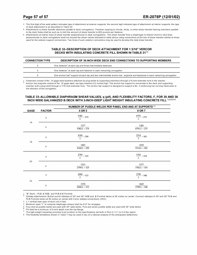
Page 57 of 57 ER-2078P (12/01/02)
4 The f irst digit of the weld pattern indicates type of attachment at exterior supports; the second digit indicates type of attachment at interior supports; the type
of deck attachment is as described in Table 32.
5 Attachments to shear transfer elements paral lel to deck corrugations: Fastener spacing to chords, struts, or other shear transfer framing mem bers parallel
to the d eck flutes shall be such as to limit the am oun t of she ar trans fer to 80 0 po und s pe r fasten er.
6 Attachments at interior lines of shear transfer perpendicular to deck corrugations: The shear transfer from a diaphragm to interior chord or strut l ines
perpendicular to deck corrugations shall not exceed the shear values indicated in table above using connections at the line of shear transfer similar to those
use d for the exterior s upp ort con nec tions. T wo lines o f such exterior c onn ection s m ay be use d to de velop the total shear tran sfer.
TABLE 32–DESCRIPTION OF DECK ATTACHMENT FOR 1 5/16" VERCORDECKS WITH INSULATING CONCRETE FILL SHOWN IN TABLE 311,2
CONNECTION TYPE DESCRIPTION OF 36-INCH-WIDE DECK END CONNECTIONS TO SUPPORTING MEMBERS
2 One fastener1 at eac h lap a nd th ree inte rm edia te faste ners
3 One fastener1 at each lap and fastener in each remaining corrugation
5 One anchor bar2 support at each lap and two intermediate anchor bar supports and fasteners in each remaining corrugation
1 Fasteners consist of No. 14 gage steel washers attached by plug welds to support ing mem bers through a d inch-d iam eter ho le in the was her.2 Anchor bar supports consist of No. 16 gage steel, ear-type washers 2¼ inches high. The anchor bar support is connected to the deck and supporting
m em ber w ith a plug we ld throu gh a 7/16 -inch-d iam eter ho le. Th e an cho r bar su ppo rt is des igne d to su ppo rt a No . 3 reinfo rcing b ar running transv erse to
the direction of the corrugation.
TABLE 33–ALLOWABLE DIAPHRAGM SHEAR VALUES, q (plf), AND FLEXIBILITY FACTORS, F, FOR 30 AND 36INCH WIDE GALVANIZED B DECK WITH 2-INCH-DEEP LIGHT WEIGHT INSULATING CONCRETE FILL 1,2,3,6,7,8
GAGE FACTOR
NUMBER OF PUDDLE WELDS PER PANEL END AND AT SUPPORTS 4,5
4 OR 5 6 OR 7
16
q
F
18
q
F
20
q
F
22
q
F
1 “B” Deck – PLB, & HSB , and PLB & B Formlok2
Sidelap attachments: Button punch sidelaps of 30" and 36" HSB and B Formlok decks at 36 inches on center. Connect sidelaps of 30" and 36" PLB and
PL B F orm lok d eck s at 36 inche s on cen ter with V erco sidela p co nne ctions (VS C).
3 L = ve rtical load spa n of de ck u nit in feet.
4 Minimum span “L” to compute diaphragm shears shall be 6'-0" for all gages.
5 Four and six puddle welds are used with 30" wide decks. Five and seven puddle welds are used with 36" wide decks.6
Fill sha ll be a m inim um of 2-inc h de pth over the top flan ge. 7
Th e light w eigh t insula ting co ncre te m ust co nform to the s pec ifications set forth in Pa rt 2.1.3 1 to 4 of the repo rt.
8 The flexibil ity l imitattions shown in Table 7 may be used in l ieu of a rational analysis of the anticipated deflections.