Embed Size (px)
Citation preview

INSTRUCTION MANUAL
VHF MARINE TRANSCEIVER
New2001
iM71

�
New2001
DECLARATIONOF CONFORMITY
We Icom Inc. Japan1-1-32, Kamiminami, Hirano-kuOsaka 547-0003, Japan
Kind of equipment: VHF MARINE TRANSCEIVER
This compliance is based on conformity with the following harmonisedstandards, specifications or documents:i) EN 301 178-2 V1.1.1 (2000-8)ii) EN 60945 2002iii) EN 60950-1 2001iv) EN 300 698-2 V1.1.1 (2000-8)v) EN 300 698-3 V1.1.1 (2001-5)vi) vii)
Type-designation: iM71
Signature
H. IkegamiGeneral Manager
Dűsseldorf 27th Dec. 2005
Himmelgeister straße 100D-40225 Dűsseldorf
Icom (Europe) GmbH
Authorized representative name
Place and date of issue
Version (where applicable):
Declare on our sole responsability that this equipment complies the essential requirements of the Radio and Telecommunications Terminal Equipment Directive, 1999/5/EC, and that any applicable Essential Test Suite measurements have been performed.
0560
CE Vers�ons of the IC-M71 wh�ch d�splay the “CE” symbol on the ser�al number label, comply w�th the essent�al requ�rements of the Europe-an Rad�o and Telecommun�cat�on Term�nal D�-rect�ve 1999/5/EC.
Th�s warn�ng symbol �nd�cates that th�s equ�pment operates �n non-harmon�sed frequency bands and/or may be subject to l�cens�ng cond�t�ons �n the country of use. Be sure to check that you have the correct vers�on of th�s rad�o or the correct program-m�ng of th�s rad�o, to comply w�th nat�onal l�cens�ng requ�rement.

IN CASE OF EMERGENCYIf your vessel requ�res ass�stance, contact other vessels and the Coast Guard by send�ng a d�stress call on Channel 16.
USING CHANNEL 16
DISTRESS CALL PROCEDURE
1. “MAYDAY MAYDAY MAYDAY.”
2. “THIS IS ������ ” (name of vessel)
3. Say your call s�gn or other �nd�cat�on of the vessel.
4. “LOCATED AT ����� ” (your pos�t�on)
5. State the nature of the d�stress and ass�s-tance requ�red.
6. G�ve any other �nformat�on wh�ch m�ght fac�l-�tate the rescue.
RECOMMENDATIONCLEAN THE TRANSCEIVER THOROUGHLY WITH FRESH WATER after exposure to saltwater, and dry �t before opera-t�on. Otherw�se, the transce�ver’s keys, sw�tches and control-lers may become �noperable due to salt crystall�zat�on.
NOTE: DO NOT wash the transce�ver �n water �f there �s any reason to suspect the waterproofing may not be effect�ve. For example, �n cases where the transce�ver/battery pack �s cracked or broken, or has been dropped, or when the battery pack �s de-tached from the transce�ver.
��
New2001

FOREWORDThank you for purchas�ng th�s Icom rad�o. The IC-M71 vhf ma-rine transceiver �s des�gned and bu�lt w�th Icom’s state of the art technology and craftsmansh�p. W�th proper care th�s product should prov�de you w�th years of trouble-free operat�on.
IMPORTANTREAD ALL INSTRUCTIONS carefully and com-pletely before us�ng the transce�ver.
SAVE THIS INSTRUCTION MANUAL—Th�s �nstruct�on manual conta�ns �mportant operat�ng �nstruct�ons for the IC-M71.
EXPLICIT DEFINITIONS
WORD DEFINITION
RDANGER!Personal death, ser�ous �njury or an explos�on may occur.
RWARNING!Personal �njury, f�re hazard or electr�c shock may occur.
CAUTION Equ�pment damage may occur.
NOTEIf d�sregarded, �nconven�ence only. No r�sk of personal �njury, fire or electr�c shock.
FEATURES
Submersible construction Bu�lt tough to w�thstand the pun�sh�ng mar�ne env�ron-
ment, the IC-M71’s submers�ble construct�on meets IPX8 requ�rements for waterproof protect�on (1.5 meter depth for 30 m�n.).
* Only when the BP-245N, flex�ble antenna, and [SP MIC] cap are attached.
In add�t�on, the new speaker gr�ll structure w�th a water self-dra�n�ng funct�on �s helpful for dra�n�ng water or sea-water eas�ly.
Dualwatch and tri-watch functions Conven�ent funct�ons that allow you to mon�tor the d�s-
tress channel (Ch 16) wh�le rece�v�ng one other channel of your cho�ce (dualwatch), or wh�le rece�v�ng one other channel of your cho�ce and the call channel (tr�-watch). See p. 16 for deta�ls.
Large, easy-to-read LCD W�th the generous d�mens�ons of 22.5(H) × 31.5(W) mm,
the IC-M71’s funct�on d�splay �s easy to read and shows operat�ng cond�t�ons at a glance. Backl�ght�ng and con-trast can be adjusted to su�t your preferences.
Simple operation The volume knob �s on top of the rad�o, wh�le the channel
buttons are on the front panel. Th�s allows for conven�ent, one-handed operat�on.���
New2001

�v
PRECAUTIONS
New2001
RWARNING! NEVER connect the transce�ver to an AC outlet. Th�s may pose a fire hazard or result �n an elec-tr�c shock.
RWARNING! NEVER hold the transce�ver so that the antenna �s closer than 2.5 cm from exposed parts of the body, espec�ally the face or eyes, wh�le transm�tt�ng. The transce�ver w�ll perform best �f the m�crophone �s 5 to 10 cm away from the l�ps and the transce�ver �s vert�cal.
NEVER connect the transce�ver to a power source other than the BP-245N. Such a connect�on w�ll ru�n the transce�v-er.
DO NOT use or place the transce�ver �n d�rect sunl�ght or �n areas w�th temperatures below –15°C or above +55°C.
KEEP the transce�ver out of the reach of ch�ldren.
KEEP the transce�ver at least 0.9 meters away from your vessel’s magnet�c nav�gat�on compass.
BE CAREFUL! The transce�ver meets IPX8* requ�re-ments for waterproof protect�on. However, once the trans-ce�ver has been dropped, waterproof protect�on cannot be guaranteed because of poss�ble damage to the transce�ver’s case or the waterproof seal.* Only when the BP-245N, flex�ble antenna, and [SP MIC] cap are
attached.
MAKE SURE the flex�ble antenna and battery pack are securely attached to the transce�ver, and that the antenna and battery pack are dry before attachment. Expos�ng the �n-s�de of the transce�ver to water w�ll result �n ser�ous damage to the transce�ver.
Icom, Icom Inc. and the Icom logo are reg�stered trademarks of Icom Incor-porated (Japan) �n Japan, the Un�ted States, the Un�ted K�ngdom, Germany, France, Spa�n, Russ�a and/or other countr�es.

v
New2001
TABLE OF CONTENTSIN CASE OF EMERGENCY ���������������� ��RECOMMENDATION ������������������� ��FOREWORD ����������������������� ���IMPORTANT ����������������������� ���EXPLICIT DEFINITIONS ����������������� ���FEATURES ����������������������� ���PRECAUTIONS ��������������������� �vTABLE OF CONTENTS ������������������ v
1 OPERATING RULES …………………………………………… 1
2 SUPPLIED ACCESSORIES AND ATTACHMENTS ……… 2–3n Suppl�ed accessor�es ���������������� 2n Attachments �������������������� 2
3 PANEL DESCRIPTION ……………………………………… 4–6n Front, top and s�de panels �������������� 4n Funct�on d�splay ������������������� 5
4 BASIC OPERATION ………………………………………… 7–13nChannel select�on ������������������ 7n Rece�v�ng and transm�tt�ng �������������� 9n Call channel programm�ng ��������������10n Lock funct�on ��������������������10n Mon�tor funct�on �������������������10n Adjust�ng the squelch level ��������������11n Backl�ght�ng funct�on �����������������11n Vo�ce scrambler operat�on ��������������11nVOX funct�on ��������������������12n AquaQuake water dra�n�ng funct�on ����������12n Channel nam�ng ������������������12
5 SCAN OPERATION (except Holland version) ………… 14–15n Scan types ���������������������14n Sett�ng TAG channels ����������������15n Start�ng a scan �������������������15
6 DUALWATCH/TRI-WATCH (except Holland version) ………16n Descr�pt�on ���������������������16n Operat�on ���������������������16
7 SET MODE …………………………………………………… 17–22n SET mode programm�ng ���������������17n SET mode �tems ������������������18
8 BATTERY CHARGING …………………………………… 23–27n Battery caut�ons �������������������23n Suppl�ed battery charger ���������������25n Opt�onal battery chargers ���������������26n Attachment ���������������������28n Detachment ��������������������28
9 OPTIONAL SWIVEL BELT CLIP ………………………………28
10 OPTIONAL SPEAKER-MICROPHONE ………………………29n HM-167 descr�pt�ons �����������������29n Attachment ���������������������29
11 TROUBLESHOOTING ……………………………………………30
12 VHF MARINE CHANNEL LIST …………………………………31
13 SPECIFICATIONS …………………………………………………32
14 OPTIONS …………………………………………………………33

1
1OPERATING RULES
DPriorities• Read all rules and regulat�ons perta�n�ng to pr�or�t�es and
keep an up-to-date copy handy. Safety and d�stress calls take pr�or�ty over all others.
• You must mon�tor Channel 16 when you are not operat�ng on another channel.
• False or fraudulent d�stress calls are proh�b�ted under law.
DPrivacy• Informat�on overheard but not �ntended for you cannot law-
fully be used �n any way.
• Indecent or profane language �s proh�b�ted.
DRadio licenses(1) SHIP STATION LICENSEWhen your craft �s equ�pped w�th a VHF FM transce�ver, you must have a current rad�o stat�on l�cense before us�ng the transce�ver. It �s unlawful to operate a sh�p stat�on wh�ch �s not l�censed.
Inqu�re through your dealer or the appropr�ate government agency for a Sh�p-Rad�otelephone l�cense. Th�s l�cense �n-cludes the call s�gn wh�ch �s your craft’s �dent�ficat�on for rad�o purposes.
(2) OPERATOR’S LICENSEA restr�cted Rad�otelephone Operator Perm�t �s the l�cense most often held by small vessel rad�o operators when a rad�o �s not requ�red for safety purposes.
The Restr�cted Rad�otelephone Operator Perm�t must be posted near the transce�ver or be kept w�th the operator. Only a l�censed rad�o operator may operate a transce�ver.
However, non-l�censed �nd�v�duals may talk over a transce�v-er �f a l�censed operator starts, superv�ses, ends the call and makes the necessary log entr�es.
A current copy of the appl�cable government rules and reg-ulat�ons �s only requ�red to be on hand for vessels �n wh�ch a rad�o telephone �s compulsory. However, even �f you are not requ�red to have these on hand �t �s your respons�b�l�ty to be thoroughly acqua�nted w�th all pert�nent rules and reg-ulat�ons.
1

2
New2001
SUPPLIED ACCESSORIES AND ATTACHMENTS2n Supplied accessoriesThe follow�ng accessor�es are suppl�ed: Qty.q Handstrap �������������������� 1w Battery charger ������������������ 1e Screws for the battery charger (M3.5×30) ������� 2r Belt cl�p (w�th screws) ��������������� 1t AC adapter* ������������������� 1y L�-Ion battery pack ���������������� 1u Flex�ble antenna ����������������� 1
*Not suppl�ed w�th some vers�ons.
q w e
r
t y
u
(Different type is supplied depending on the version)
(Different type is supplied depending on the version)
n AttachmentsD Flexible antenna
Connect the suppl�ed flex�ble an-tenna to the antenna connector.
CAUTION: Transm�tt�ng w�thout an antenna may damage the transce�ver.
NEVER carry the transce�ver by hold�ng the antenna.
D Handstrap Pass the handstrap through the loop on the top corner of the trans-ce�ver as �llustrated at left. Fac�l�tates carry�ng.
3
2SUPPLIED ACCESSORIES AND ATTACHMENTS
New2001
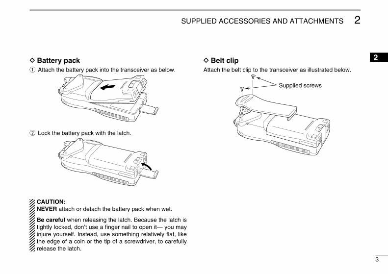
D Battery packq Attach the battery pack �nto the transce�ver as below.
w Lock the battery pack w�th the latch.
CAUTION: NEVER attach or detach the battery pack when wet.
Be careful when releas�ng the latch. Because the latch �s t�ghtly locked, don’t use a finger na�l to open �t— you may �njure yourself. Instead, use someth�ng relat�vely flat, l�ke the edge of a co�n or the t�p of a screwdr�ver, to carefully release the latch.
D Belt clipAttach the belt cl�p to the transce�ver as �llustrated below.
Supplied screws
2

4
New2001
PANEL DESCRIPTION3n Front, top and side panels
q
w
e
r
t
Microphone
!0
o
i
u
y
Speaker
Functiondisplay(p. 5)
q VOLUME CONTROL [VOL] Turns power ON and adjusts the aud�o level.
w PTT SWITCH [PTT] Push and hold to transm�t; release to rece�ve.
eMONITOR KEY [ ] • Manually opens the squelch for mon�tor�ng the channel
wh�le pushed and held. (p. 10) • Push th�s sw�tch, then adjust the squelch level w�th
[Y]/[Z]. (p. 11) • Wh�le push�ng and hold�ng th�s sw�tch, turn power ON to
enter the SET mode. (p. 17)
r CHANNEL UP/DOWN KEYS [Y]/[Z] • Selects an operat�ng channel. (pgs. 7–9) • Selects the SET mode cond�t�on of the �tem. (p. 17) • Selects the SET mode �tem when pushed w�th [ ].
(p. 17) • Checks TAG channels or changes scann�ng d�rect�on
dur�ng scan. (p. 15)
t CHANNEL 16 KEY [16•C] • Selects Channel 16 when pushed. (p. 7) • Selects call channel when pushed for 1 sec. (p. 7) • Enters call channel wr�te mode when the call channel
�s selected and th�s key �s pushed and held for 3 sec. (p. 10)

5
3PANEL DESCRIPTION
New2001
y TRANSMIT POWER/LOCK KEY [H/L•LOCK] • Selects h�gh, m�ddle or low power when pushed. (p. 9) • Toggles the lock funct�on ON/OFF when pushed and
held for 1 sec. (p. 10)
u SCAN KEY [SCAN•DUAL] • Starts and stops normal or pr�or�ty scan when pushed.
(pgs. 14, 15) • Enters watch mode when pushed and held for 1 sec. (p. 16)
i DIAL KEY [DIAL] • Selects the regular channels when pushed. (p. 8) • Selects the U.S.A.*1, Internat�onal, Canad�an*2 or ATIS*3
channel group when pushed and held for 1 sec. (p. 8) - The funct�on d�splay shows wh�ch channel group �s act�ve. *1 U.K. and Ch�na vers�ons only. *2 Ch�na vers�on only. *3 German and Holland vers�ons only. • Push to return to the cond�t�on before select�ng the channel
when the pr�or�ty channel or the call channel �s selected.
o SPEAKER-MICROPHONE CONNECTOR [SP MIC] Connects the opt�onal external speaker-m�crophone or
headset. NOTE: Attach the [SP MIC] cap when the opt�onal
speaker-m�crophone or headset �s not used.
!0 ANTENNA CONNECTOR Connects the suppl�ed antenna.
n Function displayq
we
r
t
yu
io
!1
!4
!0
!2
!3
!5
q CHANNEL NUMBER READOUT • Ind�cates the selected operat�ng channel number. • In the SET mode, �nd�cates the selected cond�t�on. • “DUP” appears when a duplex channel �s selected.
wTAG CHANNEL INDICATOR (p. 15) Appears when TAG channel �s selected.
eBATTERY INDICATOR Ind�cates rema�n�ng battery power.
Indication
Full MiddleChargingrequired No batteryBattery level
blinks when the battery is overcharged (or over voltage).
3

6
3 PANEL DESCRIPTION
New2001
rMONITOR INDICATOR (p. 10) Appears when the mon�tor funct�on �s act�vated.
tDUALWATCH/TRI-WATCH INDICATORS (p. 16) “DUAL” bl�nks dur�ng dualwatch; “TRI” bl�nks dur�ng tr�-
watch.
yVOX INDICATOR (p. 12) Appears when the VOX funct�on �s used.
uSCRAMBLER INDICATOR (pgs. 11, 22) Appears when the vo�ce scrambler �s act�vated. * The vo�ce scrambler funct�on �s ava�lable w�th some vers�ons
only.
iCHANNEL NAMING • Ind�cates or scrolls operat�ng channel name or comment.
(p. 13) • In the SET mode, �nd�cates or scrolls the selected �tem.
(pgs. 17–22)
oLOCK INDICATOR (p. 10) Appears when the lock funct�on �s act�vated.
!0ATIS INDICATOR (p. 8) Appears when the channel group, wh�ch ATIS funct�on �s
act�vated, �s selected. • Ava�lable w�th the German and Holland vers�ons only.
!1CALL CHANNEL INDICATOR (p. 7) Appears when the call channel �s selected.
!2 CHANNEL GROUP INDICATOR (p. 8) “USA*1” appears when U.S.A.; “INT” appears when Inter-
nat�onal; “CAN*2” appears when Canad�an channel group �s selected.
*1 U.K. and Ch�na vers�ons only. *2 Ch�na vers�on only.
!3TRANSMIT POWER INDICATORS (p. 9) • “LOW” appears when low power �s selected. • “MID” appears when m�ddle power �s selected. • No �nd�cat�on appears when h�gh power �s selected.
!4TRANSMIT INDICATOR (p. 9) Appears dur�ng transm�t.
!5BUSY INDICATOR (pgs. 9, 10) Appears when a s�gnal �s rece�ved or squelch �s open.

7
4BASIC OPERATION
34
nChannel selection IMPORTANT: Pr�or to us�ng the transce�ver for the first t�me, fully charge the battery pack. Th�s w�ll help max�m�ze the capab�l�ty and l�fe of the battery. To avo�d damage to the transce�ver, turn the rad�o OFF wh�le charg�ng.
D Channel 16Channel 16 (D�stress channel) �s used for establ�sh�ng �n�t�al contact w�th another stat�on and for emergency commun�-cat�ons. Channel 16 �s automat�cally mon�tored dur�ng both dualwatch and tr�-watch. Wh�le stand�ng by, you must mon�-tor Channel 16.
q Push [16•C] to select Channel 16.w Push [DIAL] to return to the cond�t�on before select-
�ng Channel 16, or push [Y]/[Z] to select the operat�ng channel.
Push
D Call channel Call channel �s the le�sure-use call channel. Each regular channel group has separate call channels. In add�t�on, the call channel �s mon�tored dur�ng tr�-watch. The call channels can be re-programmed (p. 10) and may be used to store your most often used channels �n each channel group for qu�ck re-call.
q Push and hold [16•C] for 1 sec. to select the call channel. • “CALL” and the call channel number appear. • Call channel can be re-programmed. See the “Call channel
programm�ng” on p. 10 for deta�ls.w Push [DIAL] to return to the cond�t�on before select�ng Call
channel, or push [Y]/[Z] to select the operat�ng channel.
Push
for 1 sec.
Channel 16 is programmedas a default setting.(depending on the version)

D U.S.A., International, Canadian and ATIS channels
The IC-M71 has U.S.A.*1, Internat�onal, Canad�an*2 and ATIS*3 channels. You must select the proper channels for the operat�ng area.*1 U.K. and Ch�na vers�ons only.*2 Ch�na vers�on only.*3 German and Holland vers�ons only.
q Push [DIAL] to select the regular channel.w Push [Y]/[Z] to select a channel. • “DUP” appears for duplex channels.e To change the channel group, push and hold [DIAL] for
1 sec. • Repeat unt�l you reach the des�red channel group.
For U.K. version
U.S.A. channelsInternational channels
Push and hold
for 1 sec.
8
4 BASIC OPERATION
New2001
U.S.A. channels Canadian channels
Push and hold
for 1 sec.
Push and hold
for 1 sec.
Push and hold
for 1 sec.
ATIS channelsInternational channels
Push and hold
for 1 sec.
For German and Holland versions
For China version
International channels

9
4BASIC OPERATION
New2001
4
n Receiving and transmitting
CAUTION: Transm�tt�ng w�thout an antenna may damage the transce�ver.
qRotate [VOL] clockw�se to turn power ON. • Open�ng comment scrolls across the funct�on d�splay. (p. 13) • Push [16•C] to sk�p the open�ng comment �nd�cat�on.wSet the volume and squelch level. ➥ Push [ ], and push [Z] to open the squelch. ➥ Rotate [VOL] to set the volume level. ➥ Push [ ], and push [Y]/[Z] to set the squelch level.ePush [Y]/[Z] to select the des�red channel. - When rece�v�ng a s�gnal, “ ” �nd�cator appears wh�le aud�o
�s em�tted from the speaker. - Further adjustment of [VOL] may be necessary at th�s po�nt.rPush [H/L•LOCK] to select the output power, �f necessary. - “LOW” appears when low power �s selected; “MID” appears
when m�ddle power �s selected; no �nd�cat�on when h�gh power �s selected.
- Choose low or m�d. power to conserve battery power, choose h�gh power for longer d�stance commun�cat�ons.
- Some channels are for low power only.tPush and hold [PTT] to transm�t, and speak �nto the m�cro-
phone. - The transm�t �nd�cator appears wh�le transm�tt�ng. - Channel 70 cannot be used for transm�ss�on.yRelease [PTT] to rece�ve.
IMPORTANT: To max�m�ze the readab�l�ty of your trans-m�tted s�gnal, pause a second after push�ng [PTT], hold the m�crophone 5 to 10 cm from your mouth, and speak �nto the m�crophone us�ng a normal vo�ce level.
NOTE: The transce�ver has a power save funct�on to con-serve the battery power. The power save funct�on �s auto-mat�cally act�vated when no s�gnal �s rece�ved for 5 sec.
Microphone
Speaker
r Set output power
t Push to transmity Release to receive q Power ON
w Set volume
w Set the squelch level
w Set the squelch level
e Select the channel

10
4 BASIC OPERATION
New2001
n Call channel programmingThe call channel key �s used to select Channel 16 by default (depend�ng on vers�ons), however, you can program your most often-used channel �n each channel group for qu�ck recall.
q Push and hold [DIAL] for 1 sec. several t�mes to select the des�red channel group (INT, USA, CAN, ATIS) to be pro-grammed.
w Push and hold [16•C] for 1 sec. to se-lect the call channel.
• “CALL” and call channel number appear.
e Push and hold [16•C] aga�n for 3 sec. (unt�l a long beep changes to 2 short beeps) to enter call channel program-m�ng cond�t�on.
• Call channel number to be programmed bl�nks.
r Push [Y]/[Z] to select the des�red channel.
t Push [16•C] to program the d�splayed channel as the call channel.
• The call channel number stops bl�nk�ng.
n Lock functionTh�s funct�on electron�cally locks all keys (except for [PTT], [ ] and [H/L•LOCK]) to prevent acc�dental channel changes and funct�on access.
➥ Push [H/L•LOCK] for 1 sec. to turn the lock funct�on ON or OFF.
Push
for 1 sec.
Appears while the lockfunction is in use.
n Monitor functionThe mon�tor funct�on releases the no�se squelch mute to check the volume level. See p. 19 for deta�ls of the mon�tor sw�tch act�on.
➥ Push and hold [ ] for 1 sec. to act�vate the mon�tor func-t�on.
• “ ” and “ ” appear and aud�o �s em�tted.
Push
for 1 sec.
Appears while the monitor function is in use.
11
4BASIC OPERATION
New2001
4
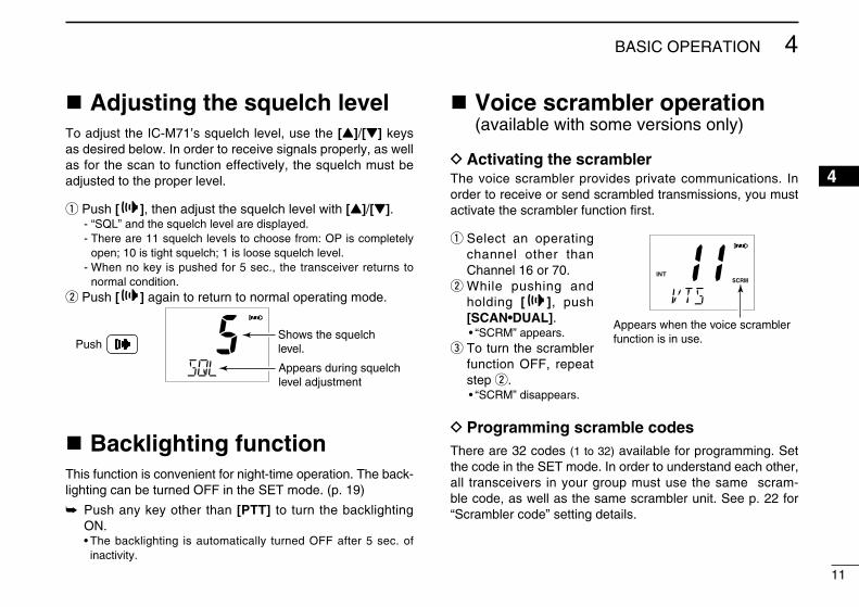
n Adjusting the squelch levelTo adjust the IC-M71’s squelch level, use the [Y]/[Z] keys as des�red below. In order to rece�ve s�gnals properly, as well as for the scan to funct�on effect�vely, the squelch must be adjusted to the proper level.
q Push [ ], then adjust the squelch level w�th [Y]/[Z]. - “SQL” and the squelch level are d�splayed. - There are 11 squelch levels to choose from: OP �s completely
open; 10 �s t�ght squelch; 1 �s loose squelch level. - When no key �s pushed for 5 sec., the transce�ver returns to
normal cond�t�on.w Push [ ] aga�n to return to normal operat�ng mode.
PushShows the squelchlevel.
Appears during squelch level adjustment
n Backlighting functionTh�s funct�on �s conven�ent for n�ght-t�me operat�on. The back-l�ght�ng can be turned OFF �n the SET mode. (p. 19)
➥ Push any key other than [PTT] to turn the backl�ght�ng ON.
• The backl�ght�ng �s automat�cally turned OFF after 5 sec. of �nact�v�ty.
n Voice scrambler operation (ava�lable w�th some vers�ons only)
D Activating the scramblerThe vo�ce scrambler prov�des pr�vate commun�cat�ons. In order to rece�ve or send scrambled transm�ss�ons, you must act�vate the scrambler funct�on first.
q Select an operat�ng channel other than Channel 16 or 70.
w Wh�le push�ng and hold�ng [ ], push [SCAN•DUAL].
• “SCRM” appears.e To turn the scrambler
funct�on OFF, repeat step w.
• “SCRM” d�sappears.
D Programming scramble codesThere are 32 codes (1 to 32) ava�lable for programm�ng. Set the code �n the SET mode. In order to understand each other, all transce�vers �n your group must use the same scram-ble code, as well as the same scrambler un�t. See p. 22 for “Scrambler code” sett�ng deta�ls.
Appears when the voice scramblerfunction is in use.

12
4 BASIC OPERATION
New2001
nVOX functionNOTE: An opt�onal headset and opt�onal headset adapter
are requ�red for the VOX operat�on.
The VOX funct�on (vo�ce operated transm�ss�on) starts transm�t-t�ng when you speak �nto the headset’s m�crophone. There �s no need to push [PTT]. The IC-M71 automat�cally returns to rece�ve mode when you stop talk�ng.
➥ Push and hold [ ], then push [H/L•LOCK] to turn the VOX funct�on ON or OFF wh�le connect�ng the headset and opt�onal headset adapter to [SP MIC] connector.
• “VOX” appears on the LCD wh�le the VOX funct�on turns ON. • The VOX ga�n and VOX delay can be set on the SET mode. (p. 22) • Dur�ng scan, dual/tr�-watch or on a transm�ss�on �nh�b�ted chan-
nel, the VOX funct�on w�ll not be act�vated.
n AquaQuake water draining functionThe IC-M71 uses a new technology to clear water away from the speaker gr�ll: AquaQuake. AquaQuake helps dra�n water away from the speaker hous�ng (water that m�ght otherw�se muf-fle the sound com�ng from the speaker). The IC-M71 em�ts a v�-brat�ng no�se when th�s funct�on �s be�ng used.
➥ Push and hold both [16•C] and [H/L•LOCK]. • A low beep tone sounds for 9 sec. to dra�n water, regardless of
[VOL] control sett�ng. • The transce�ver never accepts a key operat�on wh�le the AquaQuake
funct�on �s act�vated. And th�s funct�on won’t be act�vated when an op-t�onal speaker-m�crophone or headset �s connected.
n Channel naming The IC-M71 has a capab�l�ty to ass�gn up to 10-character channel names or comments for each operat�ng channel, �n-clud�ng each weather channel. Th�s prov�des easy recogn�-t�on of channel usage, or stat�on names, etc.
When sh�pped from the factory, the IC-M71 �s programmed w�th default names for each VHF mar�ne channel. These de-faults can be changed, �f des�red.
You may replace the factory-set open�ng comment w�th a comment of your own. The open�ng comment appears each t�me the IC-M71 �s powered ON. The comment may be up to 16 characters long.
D Available characters
(=)
(4)
(D)
(N)
(X)
(h)
(r)
(�)
(5)
(E)
(O)
(Y)
(i)
(s)
(+)
(6)
(F)
(P)
(Z)
(j)
(t)
(7)
(G)
(Q)
(a)
(k)
(u)
(,)
(8)
(H)
(R)
(b)
(l)
(v)
(/)
(9)
(I)
(S)
(c)
(m)
(w)
(0)
(Space)
(J)
(T)
(d)
(n)
(x)
(1)
(A)
(K)
(U)
(e)
(o)
(y)
(2)
(B)
(L)
(V)
(f)
(p)
(z)
(3)
(C)
(M)
(W)
(g)
(q)
(–)

13
4BASIC OPERATION
New2001
4
D Channel name/comment programmingq Push [Y]/[Z] to select a channel to
program. • Push and hold [DIAL] for 1 sec. to se-
lect a channel group, �f necessary.
w Wh�le push�ng and hold�ng [ ], push [DIAL].
• The 1st character of the currently pro-grammed name or comment bl�nks.
e Push [Y]/[Z] to select a character.
r Push [H/L•LOCK] to move to the r�ght; then push [Y]/[Z] to select a character.
• Push�ng [16•C], moves to left
t Cont�nue unt�l the des�red charac-ters have been selected, then push [DIAL] to return to normal opera-t�on.
DOpening comment programmingq Wh� le push �ng and ho ld �ng
[SCAN•DUAL], turn power ON. • “OC” �s d�splayed and the 1st character
of the currently programmed comment bl�nks.
w Push [Y]/[Z] to select a character. • Push [SCAN•DUAL] to clears the pre-
v�ously programmed open�ng comment (all d�g�ts).
e Push [H/L•LOCK] to move to the r�ght; then push [Y]/[Z] to select a character.
• Push�ng [16•C], moves to left
r Cont�nue unt�l the des�red charac-ters have been selected, then push [DIAL] to return to normal opera-t�on.
The programmed open�ng comment �s br�efly d�splayed or scrolled when the transce�ver �s powered ON.
However, the open�ng comment �nd�cat�on can be sk�pped by push�ng [16•C].
14
New2001
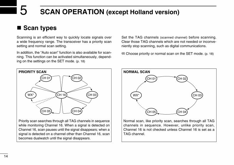
SCAN OPERATION (except Holland version)5n Scan typesScann�ng �s an effic�ent way to qu�ckly locate s�gnals over a w�de frequency range. The transce�ver has a pr�or�ty scan sett�ng and normal scan sett�ng.
In add�t�on, the “Auto scan” funct�on �s also ava�lable for scan-n�ng. Th�s funct�on can be act�vated s�multaneously, depend-�ng on the sett�ngs on the SET mode. (p. 18)
Set the TAG channels (scanned channel) before scann�ng. Clear those TAG channels wh�ch are not needed or �nconve-n�ently stop scann�ng, such as d�g�tal commun�cat�ons.
Choose pr�or�ty or normal scan on the SET mode. (p. 18)
PRIORITY SCAN
WX*
CH 01
CH 16
CH 02
CH 05 CH 04
CH 03
* Previously selected weather channel when weather alert function is ON
Pr�or�ty scan searches through all TAG channels �n sequence wh�le mon�tor�ng Channel 16. When a s�gnal �s detected on Channel 16, scan pauses unt�l the s�gnal d�sappears; when a s�gnal �s detected on a channel other than Channel 16, scan becomes dualwatch unt�l the s�gnal d�sappears.
NORMAL SCAN
CH 01 CH 02
WX*
CH 05 CH 04
CH 03
* Previously selected weather channel when weather alert function is ON.
Normal scan, l�ke pr�or�ty scan, searches through all TAG channels �n sequence. However, unl�ke pr�or�ty scan, Channel 16 �s not checked unless Channel 16 �s set as a TAG channel.

15
5SCAN OPERATION
New2001
5
n Setting TAG channelsFor more effic�ent scann�ng, add des�red channels as TAG channels or clear the TAG for unwanted channels.Untagged w�ll be sk�pped dur�ng scann�ng. TAG channels can be ass�gned to each channel group (USA, INT, CAN, ATIS) �n-dependently.
q Select the des�red channel to set as a TAG channel.w Push and hold both [Y] and [Z] for 1 sec. to set the d�s-
played channel as a TAG channel. • “ ” appears �n the funct�on d�splay.e To cancel the TAG channel sett�ng, push and hold both
[Y] and [Z] for 1 sec. • “ ” d�sappears.
Clearing All Tagged Channels in the Selected Channel GroupWh�le push�ng and hold�ng both [Y] and [Z], turn power ON to clear all TAG channels sett�ng �n the channel group.
n Starting a scanSet the pr�or�ty scan funct�on, scan resume t�mer and auto scan funct�on �n advance, us�ng the SET mode. (pgs. 18, 19)
q Make sure the des�red channel group (e.g., INT, USA, CAN, ATIS) �s selected. Move between channel groups by re-peatedly push�ng [DIAL] for 1 sec. at a t�me.
w Push [SCAN•DUAL] to start pr�or�ty or normal scan. • “SCAN” bl�nks �n the funct�on d�splay. • “16” appears on the comment �nd�cator dur�ng pr�or�ty scan. • When a s�gnal �s rece�ved, scan pauses unt�l the s�gnal d�sap-
pears or resumes after paus�ng 5 sec. accord�ng to scan re-sume t�mer sett�ng. (Channel 16 �s st�ll mon�tored dur�ng pr�or�ty scan.)
• Push [Y]/[Z] to check the scann�ng TAG channels, change the scann�ng d�rect�on or resume the scan manually.
e To stop the scan, push [SCAN•DUAL]. • “SCAN” d�sappears. • Push�ng [PTT], [16•C] or [DIAL] also stops the scan.
[Example]: Start�ng a normal scan.Scan starts
“SCAN” indication blinks
Push Push
to stop the scan
When receiving a signal, “SCAN” indi-cation blinks and audio is emitted.

16
New2001New2001
DUALWATCH/TRI-WATCH (except Holland version)6n DescriptionDualwatch mon�tors Channel 16 wh�le you are rece�v�ng another channel; tr�-watch mon�tors Channel 16 and the call channel wh�le rece�v�ng another channel.
n Operationq Select the des�red operat�ng channel.w Push [SCAN•DUAL] for 1 sec. to start dualwatch or tr�-
watch (depend�ng on the SET mode sett�ng; p. 19). • “DUAL” bl�nks dur�ng dualwatch; “TRI” bl�nks dur�ng tr�-watch. • A beep tone sounds when a s�gnal �s rece�ved on Channel 16. • Tr�-watch becomes dualwatch when rece�v�ng a s�gnal on the
call channel.e To cancel dualwatch/tr�-watch, push [SCAN•DUAL] aga�n.
DUALWATCH/TRI-WATCH SIMULATION
Dualwatch Tri-watch
Call channel
• If a s�gnal �s rece�ved on Channel 16, dualwatch/tr�-watch paus-es on Channel 16 unt�l the s�gnal d�sappears.
• If a s�gnal �s rece�ved on the call channel dur�ng tr�-watch, tr�-watch becomes dualwatch unt�l the s�gnal d�sappears.
• To transm�t on the selected channel dur�ng dualwatch/tr�-watch, push and hold [PTT].
[Example]: Operat�ng tr�-watch on INT channel 07.
Signal is received on the call channel.
A signal receive on Channel 16 always takes priority.
Tri-watch resumes after the signal disappears.
Tri-watch starts.
Push for 1 sec.

17
67
7SET MODE
New2001
n SET mode programmingSET mode �s used to change the cond�t�on of 17 transce�v-er funct�ons: beep tone funct�on, scan type, scan resume t�mer, auto scan funct�on, dual/tr�-watch funct�on, mon�tor key act�on, backl�ght�ng funct�on, LCD contrast select�on, auto power save funct�on, self check funct�on, battery voltage �n-d�cat�on, squelch sens�t�v�ty, channel name scroll type, scroll speed, scrambler code, VOX ga�n and VOX delay.
D SET mode operationqTurn power OFF.wWh�le push�ng and hold�ng [ ], turn power ON to enter
the SET mode. • “BEEP” (Beep tone funct�on sett�ng) appears.ePush [ ], or push [ ] and [Y]/[Z] to select the de-
s�red �tem.rPush [Y]/[Z] to select the des�red cond�t�on of the �tem.tTo ex�t the SET mode, push [16•C].
D SET MODE ITEMSBeep tone* Scan type‡ Scan resume timer‡ Auto scan start function‡ Dual/Tri-watch‡
Monitor keyaction
Displaybacklight
LCDcontrast
VOX delay
VOX gain
Voice scramblercode†
Scroll speed
Power savefunction
Self-check functionBattery voltage indicationSquelch sensitivityChannel name scroll type
: Push [ ], or while pushing and holding [ ], push [Y]: While pushing and holding [ ], push [Z]*Starting item†Availability may differ depending on the version.‡Not available with the Holland version.

18
7 SET MODE
New2001
n SET mode itemsD Beep tone function “ ”Selects the key touch beep sound ON or US, or turns sound OFF.• ON : A fixed beep sounds (default)• US : The preset beeps (e.g. do, re, m�) sound• OFF : S�lent operat�on
Push
Beep tone ON(default)
Beep tone OFF
D Priority scan function “ ” (except Holland vers�on)
The transce�ver has 2 scan types— normal (OFF) and pr�or�-ty (ON) scans. Normal scan searches all TAG channels �n the selected channel group. Pr�or�ty scan searches all TAG chan-nels �n sequence wh�le mon�tor�ng Channel 16.
Push
Normal scan Priority scan (default)
D Scan resume timer “ ” (except Holland vers�on)
The scan resume t�mer can be set as a pause (OFF) or t�mer scan (ON). When OFF �s selected, the scan pauses unt�l a rece�ved s�gnal d�sappears. When ON �s selected, the scan pauses for 5 sec. after rece�v�ng a s�gnal and then resumes even �f the s�gnal has been rece�ved.
Push
Scan resume timerOFF (default)
Scan resume timerON
D Auto scan function “ ” (except Holland vers�on)
The auto scan funct�on starts the des�red scan automat�cal-ly when no s�gnal �s rece�ved, and no operat�on �s performed for 30 sec.
Push
Auto scan OFF(default)
Auto scan ON

19
7SET MODE
New2001
7
D Dual/Tri-watch function “ ” (except Holland vers�on)
Th�s �tem selects dual or tr�-watch as des�red. See p. 16 for deta�ls.
Push
Dualwatch (default) Tri-watch
D Monitor key action “ ”The mon�tor key act�on cuts off the squelch funct�on tempo-rar�ly. Th�s key act�on conta�ns PUSH (Pu) or HOLD (Ho) set-t�ngs as shown below.• Pu (PUSH): After push�ng [ ] for 1 sec., the squelch opens and
em�ts aud�o. The squelch �s held open wh�le cont�nu-ously push�ng and hold�ng [ ]. (default)
• Ho (HOLD): After push�ng [ ] for 1 sec., the squelch opens and em�ts aud�o even [ ] �s released. To close the squelch, push any key.
Push
Push setting (default) Hold setting
D Backlight function “ ”Th�s funct�on �s conven�ent for n�ght-t�me operat�on. The backl�ght can be selected from ON and OFF.• The backl�ght �s automat�cally act�vated when any key except for
[PTT] �s pushed.• The backl�ght �s automat�cally turned OFF after 5 sec. of �nact�v�ty.
Push
Backlight ON(default)
Backlight OFF
D LCD contrast selection “ ”The contrast of the LCD can be selected from H� (default) and Lo.
Push
High contrast (default) Low contrast

20
7 SET MODE
New2001
D Auto power save function “ ”The auto power save funct�on reduces current dra�n by deac-t�vat�ng the rece�ver c�rcu�t for preset �ntervals. • ON : The power save funct�on �s turned ON. The power save func-
t�on w�ll be act�vated when no s�gnal �s rece�ved, and no oper-at�on �s performed for 5 sec.
• OFF : The power save funct�on �s turned OFF.
Push
Power save ON(default)
Power save OFF
D Self check function “ ”The self check funct�on �nforms you �n case a problem �s found w�th the rad�o. Self check automat�cally and qu�ck-ly runs through �ts d�agnost�c steps each t�me the rad�o �s turned ON. Afterwards, the rad�o sw�tches to normal opera-t�on mode.• Temperature : Outs�de of –35°C to +73°C (approx.)• Connected battery voltage• Water �ntrus�on
Push
Self check OFF(default)
Self check ON
When any of the bellow error messages appear, see the trou-bleshoot�ng sect�on of th�s document for adv�ce. (p. 30)
Battery voltage error Temperature error Water intrusion

21
7SET MODE
New2001
7
D Battery voltage indicator “ ”Th�s funct�on controls d�splay or non-d�splay sett�ngs of the connected battery pack’s voltage when the power �s ON.• The voltage of the connected battery pack �s d�splayed for 2 sec.
after power �s turned ON.
Push
Voltage indicationOFF (default)
Voltage indication ON
D Squelch sensitivity function “ ”When th�s funct�on �s turned ON (local), block�ng aga�nst no�se �s �mproved and the squelch �s not eas�ly affected by no�se.
Push
Squelch sensitivityOFF (default)
Squelch sensitivityON
D Channel name scroll type “ ”Selects the channel name/comment scroll type from 1 and 2.• 1: The first 7 characters are d�splayed for 1 sec. (approx.) then
scrolls. When the channel name/comment �s 7 character or less, �t does not scroll (default).
• 2: The channel name/comment scrolls regardless of the number of characters after no name/comment (blank) �s �nd�cated for 1 sec.
Push
Scroll type 1 (default) Scroll type 2
D Scrolling speed “ ”Selects the channel name/comment scroll speed.• 1: Scrolls 3.33 characters �n a second.• 2: Scrolls 2.5 characters �n a second.• 3: Scrolls 2 characters �n a second.
Push
Scroll speed 1(default)
Scroll speed 3

22
7 SET MODE
New2001
D Voice scrambler code “ ” (ava�lable w�th some vers�ons only)
There are 32 codes (1 to 32) ava�lable for programm�ng. In order to understand each other, all transce�vers �n your group must share the same scrambler code.
Push
Scramble code 1(default)
Scramble code 32
D VOX gain “ ”Adjusts the VOX ga�n level from 1 (h�gh sens�t�v�ty) to 6 (low sens�t�v�ty) when speak�ng w�th the opt�onal headset.
Push
VOX gain 3 (default) VOX gain 6
D VOX delay “ ”Sets the VOX delay t�mer (0.5 to 3.0 sec. �n 0.5 sec. steps) so that the transce�ver keeps on transm�tt�ng after you stop speak�ng.
Push
VOX delay 1.0(default)
VOX delay 3.0
23
8BATTERY CHARGING
78
n Battery cautions
• R DANGER! Use and charge only spec�fied Icom battery pack w�th Icom transce�ver. Only Icom battery pack �s test-ed and approved for use w�th Icom transce�ver. Us�ng th�rd-party or counterfe�t battery packs may cause smoke, fire, or cause the battery to burst.
D Battery caution• R DANGER! DO NOT hammer or otherw�se �mpact the
battery. Do not use the battery �f �t has been severely �m-pacted or dropped, or �f the battery has been subjected to heavy pressure. Battery damage may not be v�s�ble on the outs�de of the case. Even �f the surface of the battery does not show cracks or any other damage, the cells �ns�de the battery may rupture or catch fire.
• R DANGER! NEVER use or leave battery pack �n areas w�th temperatures above +60˚C. H�gh temperature bu�ld-up �n the battery, such as could occur near fires or stoves, �ns�de a sun-heated car, or by sett�ng the battery �n d�rect sunl�ght may cause the battery to rupture or catch fire. Ex-cess�ve temperatures may also degrade battery perfor-mance or shorten battery l�fe.
• R DANGER! DO NOT expose the battery to ra�n, snow, seawater, or any other l�qu�ds. Do not charge or use a wet battery. If the battery gets wet, be sure to w�pe �t dry before us�ng. The battery by �tself �s not waterproof.
• R DANGER! NEVER �nc�nerate a used battery pack s�nce �nternal battery gas may cause a rupture or explos�on.
• R DANGER! NEVER solder the battery term�nals, or NEVER mod�fy the battery pack. Th�s may cause heat gen-erat�on, and the battery may rupture, em�t smoke or catch fire.
• R DANGER! Use the battery only w�th the transce�ver for wh�ch �t �s spec�fied. Never use a battery w�th any other equ�pment, or for any purpose that �s not spec�fied �n th�s �n-struct�on manual.
• R DANGER! If flu�d from �ns�de the battery gets �n your eyes, bl�ndness can result. R�nse your eyes w�th clean water, w�thout rubb�ng them, and see a doctor �mmed�ate-ly.
• R WARNING! Immed�ately stop us�ng the battery �f �t em�ts an abnormal odor, heats up, or �s d�scolored or deformed. If any of these cond�t�ons occur, contact your Icom dealer or d�str�butor.
• R WARNING! Immed�ately wash, us�ng clean water, any part of the body that comes �nto contact w�th flu�d from �n-s�de the battery.
M�suse of L�th�um-Ion batter�es may result �n the follow�ng hazards: smoke, fire, or the battery may rupture. M�suse can also cause damage to the battery or degradat�on of battery performance.

24
8 BATTERY CHARGING
New2001
• R WARNING! NEVER put the battery �n a m�crowave oven, h�gh-pressure conta�ner, or �n an �nduct�on heat�ng cook-er. Th�s could cause overheat�ng, a fire, or cause the bat-tery to rupture.
• CAUTION: Always use the battery w�th�n the spec�fied tem-perature range for the transce�ver (–15˚C to +55˚C) and the battery �tself (–20˚C to +60˚C). Us�ng the battery out of �ts spec�fied temperature range w�ll reduce the battery’s performance and battery l�fe. Please note that the spec�-fied temperature range of the battery may exceed that of the transce�ver. In such cases, the transce�ver may not work properly because �t �s out of �ts operat�ng temperature range.
• CAUTION: Shorter battery l�fe could occur �f the battery �s left fully charged, completely d�scharged, or �n an excess�ve temperature env�ronment (above +45˚C) for an extended per�od of t�me. If the battery must be left unused for a long t�me, �t must be detached from the rad�o after d�scharg�ng. You may use the battery unt�l the rema�n�ng capac�ty �s about half, then keep �t safely �n a cool dry place w�th the temperature range as below;
–20˚C to +50˚C (w�th�n a month) –20˚C to +35˚C (w�th�n three months) –20˚C to +20˚C (w�th�n a year)
D Charging caution• R DANGER! NEVER charge the battery pack �n areas w�th
extremely h�gh temperatures, such as near fires or stoves, �ns�de a sun-heated car, or �n d�rect sunl�ght. In such env�-ronments, the safety/protect�on c�rcu�t �n the battery w�ll be act�vated, caus�ng the battery to stop charg�ng.
• R WARNING! DO NOT charge or leave the battery �n the battery charger beyond the spec�fied t�me for charg�ng. If the battery �s not completely charged by the spec�fied t�me, stop charg�ng and remove the battery from the battery char-ger. Cont�nu�ng to charge the battery beyond the spec�fied t�me l�m�t may cause a fire, overheat�ng, or the battery may rupture.
• R WARNING! NEVER �nsert the battery and transce�ver (battery attached to the transce�ver) �nto the charger �f �t �s wet or so�led. Th�s could corrode the battery charger term�-nals or damage the charger. The charger �s not waterproof.
• CAUTION: DO NOT charge the battery outs�de of the spec-�fied temperature range: ±0˚C to +45˚C. Icom recommends charg�ng the battery at +20˚C. The battery may heat up or rupture �f charged out of the spec�fied temperature range. Add�t�onally, battery performance or battery l�fe may be re-duced.
25
8BATTERY CHARGING
New2001
8
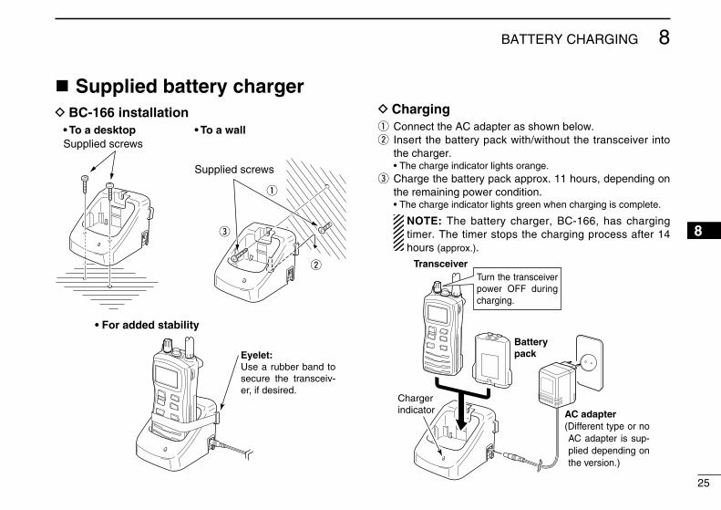
n Supplied battery chargerD BC-166 installation
q
w
e
Supplied screws
Supplied screws• To a desktop
• For added stability
• To a wall
Eyelet:Use a rubber band to secure the transceiv-er, if desired.
D Chargingq Connect the AC adapter as shown below.w Insert the battery pack w�th/w�thout the transce�ver �nto
the charger. • The charge �nd�cator l�ghts orange.e Charge the battery pack approx. 11 hours, depend�ng on
the rema�n�ng power cond�t�on. • The charge �nd�cator l�ghts green when charg�ng �s complete.
NOTE: The battery charger, BC-166, has charg�ng t�mer. The t�mer stops the charg�ng process after 14 hours (approx.).
Transceiver
Batterypack
AC adapter
Chargerindicator
(Different type or no AC adapter is sup-plied depending on the version.)
Turn the transceiver power OFF during charging.

26
8 BATTERY CHARGING
New2001
n Optional battery chargersD AD-114 installationq Connect both the 3-p�n and 10-p�n connectors of the char-
ger to the AD-114 desktop charger adapter’s plug.w Install the adapter �nto the charger �n the d�rect�on of the
arrow, then use the suppl�ed 2 screws to secure the char-ger adapter to the charger.
Desktop charger adapter
10-pin connector
3-pin connector
Suppliedscrews
D Rapid charging with the BC-119N+AD-114The opt�onal BC-119N prov�des rap�d charg�ng of battery packs. The follow�ng opt�ons are add�t�onally requ�red.• AD-114 charger adapter• An AC adapter (BC-145S) or the DC power cable (OPC-515L/
CP-23L).
AD-114 charger adapter is installed in BC-119N.
AC adapter(A different type, or no AC adapter is supplied, de-pending on the version.)
Optional OPC-515L (for 13.8 V power source) or CP-23L (for 12 V cigarette lighter socket) can be used instead of the AC adapter.
Transceiver
Battery pack
Turn power OFF

27
8BATTERY CHARGING
New2001
8
D Rapid charging with the BC-121N+AD-114The opt�onal BC-121N allows up to 6 battery packs to be charged s�multaneously. The follow�ng opt�ons are add�t�on-ally requ�red.• S�x AD-114 charger adapters• An AC adapter (BC-157) or the DC power cable (OPC-656)
Transceiver
Battery packAC adapter(Purchase separately) AD-114 charger adapters
are installed in each slot.
DC power cable (OPC-656)(Connect with the DC power supply; 13.8 V/at least 7 A)
Turn power OFF
28
New2001
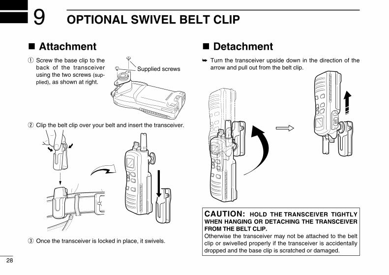
OPTIONAL SWIVEL BELT CLIP9n Attachmentq Screw the base cl�p to the
back of the transce�ver us�ng the two screws (sup-pl�ed), as shown at r�ght.
w Cl�p the belt cl�p over your belt and �nsert the transce�ver.
e Once the transce�ver �s locked �n place, �t sw�vels.
n Detachment➥ Turn the transce�ver ups�de down �n the d�rect�on of the
arrow and pull out from the belt cl�p.
CAUTION: HOLD THE TRANSCEIVER TIGHTLY WHEN HANGING OR DETACHING THE TRANSCEIVER FROM THE BELT CLIP.Otherw�se the transce�ver may not be attached to the belt cl�p or sw�velled properly �f the transce�ver �s acc�dentally dropped and the base cl�p �s scratched or damaged.
Supplied screws
29
10OPTIONAL SPEAKER-MICROPHONE
910
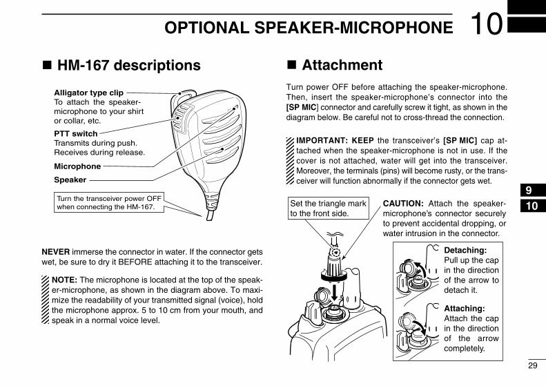
n HM-167 descriptions
PTT switchTransmits during push.Receives during release.
Microphone
Speaker
Alligator type clipTo attach the speaker-microphone to your shirt or collar, etc.
Turn the transceiver power OFF when connecting the HM-167.
NEVER �mmerse the connector �n water. If the connector gets wet, be sure to dry �t BEFORE attach�ng �t to the transce�ver.
NOTE: The m�crophone �s located at the top of the speak-er-m�crophone, as shown �n the d�agram above. To max�-m�ze the readab�l�ty of your transm�tted s�gnal (vo�ce), hold the m�crophone approx. 5 to 10 cm from your mouth, and speak �n a normal vo�ce level.
n AttachmentTurn power OFF before attach�ng the speaker-m�crophone. Then, �nsert the speaker-m�crophone’s connector �nto the [SP MIC] connector and carefully screw �t t�ght, as shown �n the d�agram below. Be careful not to cross-thread the connect�on.
IMPORTANT: KEEP the transce�ver’s [SP MIC] cap at-tached when the speaker-m�crophone �s not �n use. If the cover �s not attached, water w�ll get �nto the transce�ver. Moreover, the term�nals (p�ns) w�ll become rusty, or the trans-ce�ver w�ll funct�on abnormally �f the connector gets wet.
Set the triangle mark to the front side.
CAUTION: Attach the speaker- microphone’s connector securely to prevent accidental dropping, or water intrusion in the connector.
Detaching:Pull up the cap in the direction of the arrow to detach it.
Attaching:Attach the cap in the direction of the arrow completely.
PROBLEM
The transce�ver does not turn ON.
No sound comes from the speaker.
Transm�tt�ng �s �mposs�-ble, or h�gh power cannot be selected.
The d�splayed channel cannot be changed.
Scan does not start.
No beep sounds.
Self check error.(Temperature)
Self check error.(Battery voltage)
Transm�tt�ng cont�nuously wh�le not speak�ng when us�ng VOX funct�on.
“CHARGE” comment bl�nks
30
New2001
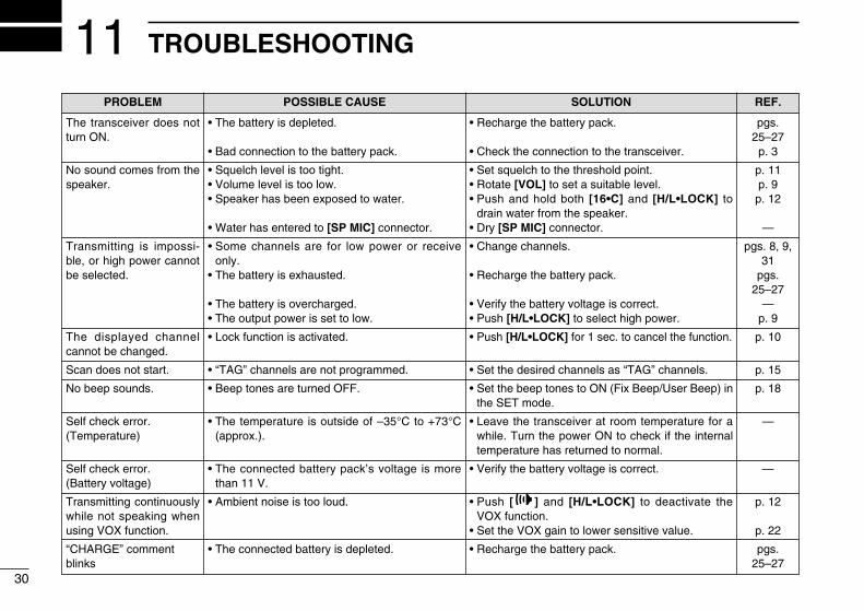
TROUBLESHOOTING11POSSIBLE CAUSE
• The battery �s depleted.
• Bad connect�on to the battery pack.
• Squelch level �s too t�ght.• Volume level �s too low.• Speaker has been exposed to water.
• Water has entered to [SP MIC] connector.
• Some channels are for low power or rece�ve only.
• The battery �s exhausted.
• The battery �s overcharged.• The output power �s set to low.
• Lock funct�on �s act�vated.
• “TAG” channels are not programmed.
• Beep tones are turned OFF.
• The temperature �s outs�de of –35°C to +73°C (approx.).
• The connected battery pack’s voltage �s more than 11 V.
• Amb�ent no�se �s too loud.
• The connected battery �s depleted.
SOLUTION
• Recharge the battery pack.
• Check the connect�on to the transce�ver.
• Set squelch to the threshold po�nt.• Rotate [VOL] to set a su�table level.• Push and hold both [16•C] and [H/L•LOCK] to
dra�n water from the speaker.• Dry [SP MIC] connector.
• Change channels.
• Recharge the battery pack.
• Ver�fy the battery voltage �s correct.• Push [H/L•LOCK] to select h�gh power.
• Push [H/L•LOCK] for 1 sec. to cancel the funct�on.
• Set the des�red channels as “TAG” channels.
• Set the beep tones to ON (F�x Beep/User Beep) �n the SET mode.
• Leave the transce�ver at room temperature for a wh�le. Turn the power ON to check �f the �nternal temperature has returned to normal.
• Ver�fy the battery voltage �s correct.
• Push [ ] and [H/L•LOCK] to deact�vate the VOX funct�on.
• Set the VOX ga�n to lower sens�t�ve value.
• Recharge the battery pack.
REF.
pgs. 25–27p. 3
p. 11p. 9p. 12
—
pgs. 8, 9, 31
pgs. 25–27
—p. 9
p. 10
p. 15
p. 18
—
—
p. 12
p. 22
pgs. 25–27

31
12VHF MARINE CHANNEL LIST
1112
Channel No. Frequency (MHz)INT USA*1 CAN*2 Transmit Receive01 01 156.050 160.650
01A 156.050 156.050 02 02 156.100 160.700 03 03 156.150 160.750
03A 156.150 156.150 04 156.200 160.800
04A 156.200 156.200 05 156.250 160.850
05A 05A 156.250 156.250 06 06 06 156.300 156.300 07 156.350 160.950
07A 07A 156.350 156.350 08 08 08 156.400 156.400 09 09 09 156.450 156.450 10 10 10 156.500 156.500 11 11 11 156.550 156.550 12 12 12 156.600 156.600 13 13*5 13*5 156.650 156.650 14 14 14 156.700 156.700
15*3 15*5 15*5 156.750 156.750 16 16 16 156.800 156.800
17*3 17*5 17*5 156.850 156.850 18 156.900 161.500
18A 18A 156.900 156.900
Channel No. Frequency (MHz)INT USA*1 CAN*2 Transmit Receive19 156.950 161.550
19A 19A 156.950 156.950 20 20 20*5 157.000 161.600
20A 157.000 157.000 21 21 157.050 161.650
21A 21A 157.050 157.050 21b Rx Only 161.650
22 157.100 161.700 22A 22A 157.100 157.100
23 23 157.150 161.750 23A 157.150 157.150
24 24 24 157.200 161.800 25 25 25 157.250 161.850
25b Rx only 161.850 26 26 26 157.300 161.900 27 27 27 157.350 161.950 28 28 28 157.400 162.000
28b Rx Only 162.000 37A*6 157.850 157.850
60 60 156.025 160.625 61 156.075 160.675
61A 61A 156.075 156.075 62 156.125 160.725
62A 156.125 156.125
Channel No. Frequency (MHz)INT USA*1 CAN*2 Transmit Receive63 156.175 160.775
63A 156.175 156.175 64 64 156.225 160.825
64A 64A 156.225 156.225 65 156.275 160.875
65A 65A 156.275 156.275 66 156.325 160.925
66A 66A*5 156.325 156.325 67 67*5 67 156.375 156.375 68 68 68 156.425 156.425 69 69 69 156.475 156.475 70 70 70 Rx Only 156.525 71 71 71 156.575 156.575 72 72 72 156.625 156.625 73 73 73 156.675 156.675 74 74 74 156.725 156.725
75*4 75*5 75*5 156.775 156.775 76*4 76*5 76*5 156.825 156.825 77 77*5 77*5 156.875 156.875 78 156.925 161.525
78A 78A 156.925 156.925 79 156.975 161.575
79A 79A 156.975 156.975 80 157.025 161.625
Channel No. Frequency (MHz)INT USA*1 CAN*2 Transmit Receive
80A 80A 157.025 157.025 81 157.075 161.675
81A 81A 157.075 157.075 82 157.125 161.725
82A 82A 157.125 157.125 83 83 157.175 161.775
83A 83A 157.175 157.175 83b Rx Only 161.775
84 84 84 157.225 161.825 84A 157.225 157.225
85 85 85 157.275 161.875 85A 157.275 157.275
86 86 86 157.325 161.925 86A 157.325 157.325 87 87 157.375 161.975
87 87A 157.375 157.375 88 88 157.425 162.025
88 88A 157.425 157.425 P4*6 161.425 161.425
*1 Ava�lable for U.K. and Ch�na vers�ons only. *2 Ava�lable for Ch�na vers�on only.*3 Channels 15 and 17 may also be used for on-board commun�cat�ons prov�ded the effect�ve rad�ated power does not exceed 1 W, and subject to the nat�onal reg-
ulat�ons of the adm�n�strat�on concerned when these channels are used �n �ts terr�tor�al waters.*4 The output power of channels 75 and 76 are l�m�ted to low power (1 W) only. The use of these channels should be restr�cted to nav�gat�on-related commun�ca-
t�ons only and all precaut�ons should be taken to avo�d harmful �nterference to channel 16, e.g. by means geograph�cal separat�on.*5 Low power only.*6 UK mar�na channels: M1=37A (Tx/Rx: 157.850 MHz), M2=P4 (Tx/Rx: 161.425 MHz) for U.K. vers�on only.NOTE: S�mplex channels, 3, 21, 23, 61, 64, 81, 82 and 83 CANNOT be lawfully used by the general publ�c �n U.S.A. waters.

32
New2001New2001
SPECIFICATIONS13D GENERAL• Frequency coverage : TX 156.000–161.450 MHz
RX 156.000–163.425 MHz• Mode : 16K0G3E• Power supply requ�rement : Spec�fied Icom’s battery pack only• Current dra�n (at 7.2 V DC; approx.):
TX H�gh (at 6 W) 1.7 ATX M�d. (at 3 W) 1.3 ATX Low (at 1 W) 0.7 ATX Low (at 0.5 W) 0.6 ARX Max. aud�o 0.4 A (�nternal speaker) 0.2 A (external speaker)
• Usable temperature range : –15°C to +55°C• Frequency error : ±1.5 kHz• Antenna connector : SMA (50 Ω nom�nal)• D�mens�ons : 52.5(W) × 125(H) × 30(D) mm
(Project�ons not �ncluded)• We�ght : Approx. 320 g
(�ncl. BP-245N, antenna, and belt cl�p)
D TRANSMITTER• Output power (at 7.5 V DC) : 6 W (H�gh), 3 W (M�ddle)
and 1 W (Low) ( 1 W (H�gh) and 0.5 W (Low) for German
vers�on depend�ng on the pre-sett�ng.)• Modulat�on system : Var�able reactance frequency mod-
ulat�on• Max. frequency dev�at�on : ±5 kHz• Adjacent channel power : 70 dB• Spur�ous em�ss�ons : 0.25 µW
D RECEIVER• Rece�ve system : Double-convers�on superhetero-
dyne• Sens�t�v�ty (20 dB SINAD) : –2 dBµ emf typ�cal• Squelch sens�t�v�ty : –6 dBµ emf typ�cal (at threshold)• Intermodulat�on reject�on rat�o : 68 dB • Spur�ous response reject�on rat�o:
70 dB • Adjacent channel select�v�ty : 70 dB • Aud�o output power :
Internal speaker 0.6 W typ�cal at 10% d�stort�on w�th an 8 Ω load
External speaker 0.2 W at 10% d�stort�on w�th an 8 Ω load
All stated specifications are subject to change without notice or obligation.

33
1314
New2001
14OPTIONS
D BATTERY PACK• BP-245N L�-Ion battery pack
Same as that suppl�ed w�th the transce�ver. Voltage : 7.4 V Capac�ty : 1900 mAh (m�n�mum)/2000 mAh (typ�cal)
D CHARGERS• BC-119N desktop charger + AD-114 charger adapter
+ BC-145S ac adapter
For rap�d charg�ng of battery packs. An AC adapter �s suppl�ed w�th the charger depend�ng on vers�ons. Charg�ng t�me: approx. 3 to 4 hours
• BC-121N multi-charger + AD-114 charger adapter (6 pcs.) + BC-157S ac adapter
For rap�d charg�ng of up to 6 battery packs (s�x AD-114’s are re-qu�red) s�multaneously. An AC adapter should be purchased sepa-rately. Charg�ng t�me: approx. 3 to 4 hours.
• BC-166 desktop charger + BC-147S ac adapter
Used for regular charg�ng of battery pack. Same as that suppl�ed w�th the transce�ver. Charg�ng t�me: approx. 11 to 12 hours
D BELT CLIPS• MB-103 belt clip
Same as that suppl�ed w�th the transce�ver.• MB-86 swivel belt clip
Belt cl�p for sw�vel type.
D DC CABLES• CP-23L cigarette lighter cable
Charges the battery pack through a 12 V c�garette l�ghter socket. (For BC-119N)
• OPC-515L/OPC-656 dc power cables
Charges the battery pack us�ng 13.8 V power source �nstead of the AC adapter.
OPC-515L: For BC-119N OPC-656 : For BC-121N
D OTHER OPTIONS• HM-167 speaker-microphone
Full s�zed speaker-m�crophone �nclud�ng an all�gator cl�p to attach the m�crophone to your sh�rt, collar, etc. The HM-167 meets IPX8 requ�rements for waterproof protect�on. However, once �t has been dropped, the IP rat�ng cannot be guaranteed because of poss�ble damage to �t’s case or the waterproof seal.
• HS-94/HS-95/HS-97 headset + OPC-1392 headset adapter
HS-94: Ear-p�ece type HS-95: Neck-arm type HS-97: Throat m�crophone
*These headsets and headset adapter are non-waterproof.• FA-S59V/FA-S64V flexible antenna
Same as that suppl�ed w�th the transce�ver.
Approved Icom opt�onal equ�pment �s des�gned for opt�mal perfor-mance when used w�th an Icom transce�ver.Icom �s not respons�ble for the destruct�on or damage to an Icom transce�ver �n the event the Icom transce�ver �s used w�th equ�pment that �s not manufactured or approved by Icom.
Ava�lable or appl�cable opt�ons may d�ffer accord�ng to countr�es. Ask your author�zed dealer for deta�ls.

1-1-32 Kam�m�nam�, H�rano-ku, Osaka 547-0003, Japan
New2001
<Intended Country of Use>
GER FRA ESP SWE
AUT NED POR DEN
GBR BEL ITA FIN
IRL LUX GRE SUI
NOR
A-6480D-1EU-uPr�nted �n Japan© 2006–2010 Icom Inc.Pr�nted on recycled paper w�th soy �nk.