Embed Size (px)
Citation preview

INSTRUCTION MANUAL
This device complies with Part 15 of the FCC Rules. Operation is subject to the condition that this device does not cause harmful interference.
UHF MOBILE TRANSCEIVER
iF2821/DiF2721/D
Above photo shows the IC-F1721/D or IC-F2721/D.
VHF MOBILE TRANSCEIVER
iF1821/DiF1721/D

i
IMPORTANTREAD ALL INSTRUCTIONS carefully and com-pletely before using the transceiver.
SAVE THIS INSTRUCTION MANUAL — This instruction manual contains important oper ating instruc-tions for the IC-F1721, IC-F1721D, IC-F1821, IC-F1821D, IC-F2721, IC-F2721D, IC-F2821 and IC-F2821D VHF/UHF MOBILE TRANSCEIVERS.
See the operating guide for details of MDC 1200 system operation. Consult with your Icom dealer or system opera-tor for details concerning your transceiver’s programming.
Icom, Icom Inc. and the Icom logo are registered trademarks of Icom Incor-porated (Japan) in Japan, the United States, the United Kingdom, Germany, France, Spain, Russia and/or other countries.All other products or brands are registered trademarks or trademarks of their respective holders.
EXPLICIT DEFINITIONS
WORD DEFINITION
RWARNING!Personal injury, fire hazard or electric shock may occur.
CAUTION Equipment damage may occur.
NOTEIf disregarded, inconvenience only. No risk of personal injury, fire or electric shock.
This instruction manual includes some functions which are usable only when they are preprogrammed by your dealer.Ask your dealer for details.

RWARNING! NEVER connect the transceiver to an AC outlet. This may pose a fire hazard or result in an electric shock.
RWARNING! NEVER place the transceiver where normal operation of the vehicle may be hindered or where it could cause bodily injury.
RWARNING! NEVER connect the transceiver to a power source of more than 16 V DC such as a 24 V battery. This connection will ruin the transceiver.
RWARNING! NEVER cut the DC power cable be-tween the DC plug and fuse holder. If an incorrect connection is made after cutting, the transceiver might be damaged.
CAUTION: NEVER allow children to touch the trans-ceiver.
CAUTION: NEVER expose the transceiver to rain, snow or any liquids.
USE the specified microphone only. Other microphones have different pin assignments and may damage the trans-ceiver.
DO NOT use or place the transceiver in areas with tem-peratures below –30°C (–22°F) or above +60°C (+140°F), or in areas subject to direct sunlight, such as the dashboard.
DO NOT operate the transceiver without running the ve-hicle’s engine. The vehicle’s battery will quickly run out when the transceiver transmits while the vehicle’s engine is OFF.
DO NOT place the transceiver in excessively dusty envi-ronments.
DO NOT place the transceiver against walls. This will ob-struct heat dissipation.
DO NOT use the chemical agents such as benzine or alco-hol when cleaning, as they damage the transceiver surfaces.
BE CAREFUL! The transceiver will become hot when operating continuously for long periods.
Approved Icom optional equipment is designed for optimal performance when used with an Icom transceiver.Icom is not responsible for the destruction or damage to an Icom transceiver in the event the Icom transceiver is used with equipment that is not manufactured or approved by Icom.
For U.S.A. onlyCAUTION: Changes or modifications to this transceiver, not expressly approved by Icom Inc., could void your authority to operate this transceiver under FCC regulations.
PRECAUTIONS
ii

iii
ABOUT APCO PROJECT 25This device made under license under one or more of the following US patents: #4,590,473, #4,636,791, #5,148,482, #5,185,796, #5,271,017, #5,377,229.
The IMBE™ voice coding Technology embodied in this prod-uct is protected by intellectual property rights including patent rights, copyrights and trade secrets of Digital Voice Systems, Inc. This voice coding Technology is licensed solely for use within this Communications Equipment. The user of this Tech-nology is explicitly prohibited from attempting to decompile, re-verse engineer, or disassemble the Object Code, or in any other way convert the Object Code into a human-readable form. U.S. Pat. Nos. #5,870,405, #5,826,222, #5,754,974, #5,701,390, #5,715,365, #5,649,050, #5,630,011, #5,581,656, #5,517,511, #5,491,772, #5,247,579, #5,226,084, #5,195,166.
FCC INFORMATION• FOR CLASS A UNINTENTIONAL RADIATORS:This equipment has been tested and found to comply with the limits for a Class A digital device, pursuant to part 15 of the FCC Rules. These limits are designed to provide reasonable protection against harmful interference when the equipment is operated in a commercial environment. This equipment generates, uses, and can radiate radio frequency energy and, if not installed and used in accordance with the instruc-tion manual, may cause harmful interference to radio com-munications.Operation of this equipment in a residential area is likely to cause harmful interference in which case the user will be re-quired to correct the interference at his own expense.
iv
TABLE OF CONTENTSIMPORTANT .......................................................................... iEXPLICIT DEFINITIONS ....................................................... iPRECAUTIONS .................................................................... iiABOUT APCO PROJECT 25 .............................................. iiiFCC INFORMATION ........................................................... iiiTABLE OF CONTENTS ....................................................... iv
1 PANEL DESCRIPTION ................................................1–8Front panel ■ ...................................................................1Function display ■ ...........................................................2Programmable function keys ■ ........................................3
2 BASIC OPERATION ..................................................9–14Turning power ON ■ ........................................................9Channel selection ■ ........................................................9Call procedure ■ ............................................................10Receiving and transmitting ■ .........................................10User Set mode ■ ...........................................................14Scrambler function ■ .....................................................14
3 BIIS OPERATION ....................................................15–25Default setting ■ ............................................................15Receiving a call ■ ..........................................................15Transmitting a call ■ ......................................................17Receiving a message ■ .................................................19Transmitting a status ■ ..................................................21Transmitting an SDM (Short Data Message) ■ .............22
Position data transmission ■ .........................................24Printer connection ■ ......................................................24Digital ANI ■ ..................................................................24Auto emergency transmission ■ ....................................24Stun function ■ ..............................................................25BIIS indication ■ ............................................................25Priority A channel selection ■ ........................................25Horn output ■ ................................................................25
4 CONNECTION AND MAINTENANCE ....................26–30Rear panel connection ■ ...............................................26Supplied Accessories ■ .................................................27Mounting the transceiver ■ ............................................28Optional OPC-617 installation ■ ....................................28 Optional UT-109 or UT-110installation ■ .......................29Antenna ■ ......................................................................30Fuse replacement ■ ......................................................30Cleaning ■ .....................................................................30Options ■ .......................................................................30
5 SAFETY TRAINING INFORMATION .......................31–34
1
1 PANEL DESCRIPTION
Front panel ■
Icom Inc
yo ru ti
q e*w
e*
IC-F1721/D
IC-F1821/D
F2721/D
F2821/D
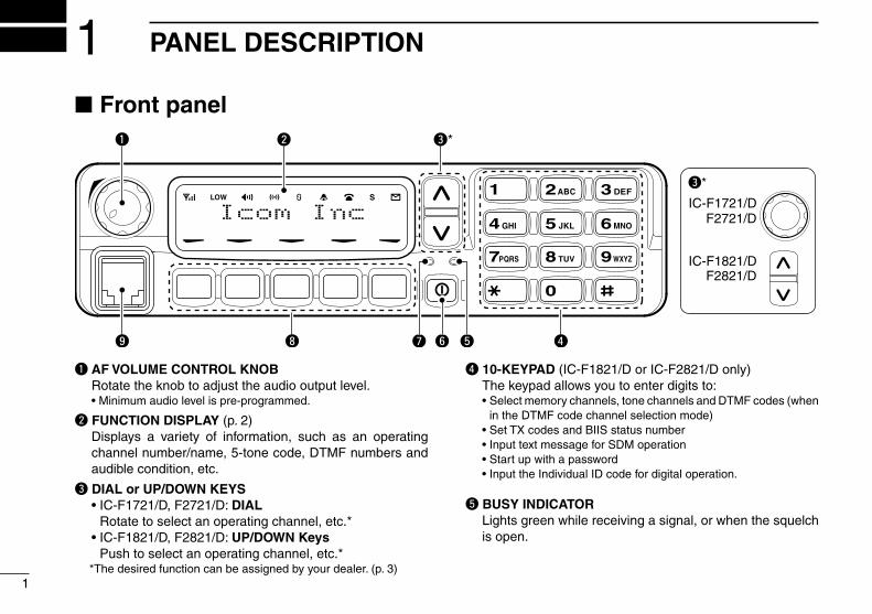
q AF VOLUME CONTROL KNOB Rotate the knob to adjust the audio output level. •Minimumaudiolevelispre-programmed.
w FUNCTION DISPLAY (p. 2) Displays a variety of information, such as an operating
channel number/name, 5-tone code, DTMF numbers and audible condition, etc.
e DIAL or UP/DOWN KEYS •IC-F1721/D,F2721/D:DIAL
Rotate to select an operating channel, etc.* •IC-F1821/D,F2821/D:UP/DOWN Keys
Push to select an operating channel, etc.* *The desired function can be assigned by your dealer. (p. 3)
r 10-KEYPAD (IC-F1821/D or IC-F2821/D only) The keypad allows you to enter digits to: •Selectmemorychannels,tonechannelsandDTMFcodes(when
in the DTMF code channel selection mode) •SetTXcodesandBIISstatusnumber •InputtextmessageforSDMoperation •Startupwithapassword •InputtheIndividualIDcodefordigitaloperation.
t BUSY INDICATOR Lights green while receiving a signal, or when the squelch
is open.

2
1PANEL DESCRIPTION
12345678910111213141516
y POWER SWITCH [POWER] Push to turn the power ON and OFF. •ThefollowingfunctionsareavailableatpowerONasoptions: - Automatic scan start - Password prompt - Set mode
u TRANSMIT INDICATOR Lights red while transmitting.
i DEALER-PROGRAMMABLE KEYS Desired functions can be programmed independently by
your dealer. (p. 3)
In this instruction manual, these keys are from the left, called [P0]/[P1]/[P2]/[P3]/[P4].
o MICROPHONE CONNECTOR Connect the supplied microphone or optional DTMF mi-
crophone.
NEVER connect non-specified microphones. The pin assignments may be different and the transceiver may be damaged.
D MICROPHONEThe supplied or optional microphone has a PTT switch and a hanger hook.•Thefollowingfunctionsareavailablewhenthemicrophoneisonor
off hook: - Automatic scan start when on hook. - Automatic priority channel selection when off hook. - Sets to ‘Inaudible’ condition (mute condition) when on hook. - Sets to ‘Audible’ condition (unmute condition) when off hook.
Function display ■
136.1 Nar
q w e r t y u i o
!1
!0
q SIGNAL STRENGTH INDICATOR Indicates relative signal strength level.
w LOW POWER INDICATOR Appears when low output power is selected.
e AUDIBLE INDICATOR Appears when the channel is in the ‘audible’ (unmute) ➥
condition. Appears when the specified 2/5-tone/BIIS code is re- ➥
ceived.
r COMPANDER INDICATOR Appears when the compander function is activated.
t SCRAMBLER INDICATOR Appears when the voice scrambler function is activated.

3
1 PANEL DESCRIPTION
Function display (Continued) ■
y BELL INDICATOR Appears/blinks when the specific 2/5-tone/BIIS code is re-
ceived, according to the pre-programming.
u CALL CODE MEMORY INDICATOR Appears when the call code memory is selected.
i SDM MEMORY INDICATOR Appears when the SDM memory is displayed.
o SDM INDICATOR Appears when an SDM is received, or a transmit SDM is
selected.
!0 ALPHANUMERIC DISPLAY Displays an operating channel number, channel name, Set
mode contents, DTMF code, etc. The indication mode can be selected from 1 line or 2 lines.
Ask your dealer for details. In this instruction manual, the LCD illustration is described
using the 2 lines indication mode.
!1 ACTIVATED KEY INDICATOR Appears above the key assigned as [DIGITAL] key when
that key has been activated.
Programmable function keys ■
The following functions can be assigned to [DIAL]*, [UP], [DOWN], [P0], [P1], [P2], [P3] and [P4] programmable func-tion keys.Consult your Icom dealer or system operator for details con-cerning your transceivers programming.If the programmable function names are bracketed in the fol-lowing explanations, the specific key is used to activate the function depends on the programming.* The functions you can assign to [DIAL] are limited. (Only functions marked with ✩ can be assigned.)
✩ CH UP AND DOWN KEYS Push (or Rotate)* to select an operating channel. ➥
Push (or Rotate)* to select a transmit code channel after ➥
pushing [TX Code CH Select]. Push (or Rotate)* to select a DTMF channel after pushing ➥
[DTMF Autodial]. Push (or Rotate)* to select a scan group after pushing and ➥
holding [Scan A Start/Stop]/[Scan B Start/Stop]. Push (or Rotate)* to select a BIIS code, status number or ➥
SDM after pushing [Digital]. Push (or Rotate)* to select an Individual ID code or Talk- ➥
group ID code after pushing [Individual] or [Talkgroup].* Rotate when this function is assigned to [DIAL].
✩ ZONE UP AND DOWN KEY (This function is for [DIAL] only)Rotate to select the desired zone.

4
1PANEL DESCRIPTION
12345678910111213141516
ZONE KEYPush this key, then select the desired zone using [CH Up]/ [CH Down].
What is “zone”?—The desired channels are assigned into a zone according to the intended use for grouping. For example, ‘Staff A’ and ‘Staff B’ are assigned into a “Business” zone, and ‘John’ and ‘Cindy’ are assigned into a “Private” zone.
SCAN A START/STOP KEY This key’s operation depends on the Power ON Scan set- ➥
ting. When the power ON scan function is turned OFF; Push to start and cancel scanning operation. In case of
transmission during scan, cancels scanning. When the power ON scan function is turned ON; Push to pause scanning. Scanning resumes after a speci-
fied time period has passed. In case of transmission during scan, pauses scanning. Scanning resumes after a specified time period has passed after the transmission is finished. Push and hold this key for 1 sec. to indicate the scan group, ➥
then select the desired group using [CH Up]/[CH Down].
SCAN B START/STOP KEY Push to start and cancel scanning operation. In case of ➥
transmission during scan, pauses scanning. Scanning re-sumes after a specified time period has passed after the transmission is finished. Push and hold this key for 1 sec. to indicate the scan group, ➥
then select the desired group using [CH Up]/[CH Down].
SCAN ADD/DEL (TAG) KEYPush to add or delete the selected channel to/from the scan group.
PRIO A/B KEYS Push to select Priority A or Priority B channel. ➥
Push and hold [Prio A (Rewrite)] to rewrite the Prio A ➥
channel.
MR-CH 1/2/3/4 KEYSPush to select an operating channel directly.
MONI (AUDI) KEY Mute and release the CTCSS (DTCS) or 2-tone squelch ➥
mute. Open any squelch/deactivate any mute while push-ing this key. (LMR operation only) ➥ Activates one of (or two of) the following functions on each channel independently: (PMR or BIIS PMR operation only)
•Pushandholdtoun-mutethechannel(audioisemitted;‘Audible’condition).
•Pushtomutethechannel(setsto‘Inaudible’only). •Pushtoun-mutethechannel(setsto‘Audible’only). •Pushafterthecommunicationisfinishedtosenda‘resetcode’.
NOTE: The un-mute condition (‘Audible’ condition) may automatically return to the mute condition (‘Inaudible’ con-dition) after a specified period depending on program-ming.

5
1 PANEL DESCRIPTION
PUBLIC ADDRESS KEYWhile in the hailer mode, push this key for the audio output via the hailer amplifier. Ask your dealer for details.While in the normal mode, the audio output via the cable can be controlled from the transceiver separately from [VOL] con-trol knob when an optional OPC-617 acc cable is installed.•Thisaudiooutputcanbeusedasa‘publicaddress’functionwhenan
external audio amplifier and speaker are connected additionally.•Pushthiskey,thenspeakintothemicrophonewhilepushingthe
PTT switch.•[CHUp]/[CHDown]allowyoutosettheaudiooutput levelfrom
minimum to maximum.
RX SPEAKER KEYWhile in the hailer mode, the external speaker drive function is also available simultaneously when the external connec-tions are made for the ‘public address’ function. The received audio can be heard via the external speaker when this key is pushed.•Thisfunctionisusefulwhenyouareoutofthevehicle.•Theaudiooutputlevelislinkedtothetransceiver’svolumecontrol.
LIGHT KEYPush to turn the transceiver’s backlight ON for about 5 sec. when the backlight function is turned OFF in the User Set mode.
LOCK KEYPush and hold to electronically lock all programmable keys except the following:[Call] (incl. Call A and Call B), [Moni(Audi)] and [Emergency].
HIGH/LOW KEYPush to select the transmit output power temporarily or per-manently, depending on the pre-setting.•Askyourdealerfortheoutputpowerlevelforeachselection.
C.TONE CH ENT KEYPush to select the continuous tone channel using [CH Up]/ [CH Down] to change the tone frequency/code setting after pushing this key. The selected channel remains set as the continuous tone channel until another channel is designated as such.
TALK AROUND KEYTurn the talk around function ON and OFF.•Thetalkaroundfunctionequalizesthetransmitfrequencytothe
receive frequency for transceiver-to-transceiver communication.
WIDE/NARROW KEYPush to toggle the IF bandwidth between wide and narrow.•Thewidepassbandwidthcanbeselectedfrom25.0or20.0kHz
using the CS-F70/F1700 cloning software. (PMR or BIIS PMR operation only) Ask your Dealer for details.
DTMF AUTODIAL KEY ➥ Push to enter the DTMF channel selection mode. Then se-lect the desired DTMF channel using [CH Up]/[CH Down]. After selecting the desired DTMF channel, push this key to ➥
transmit the DTMF code.
SCRAMBLER FUNCTIONPush to toggle the voice scrambler function ON and OFF.
6
1PANEL DESCRIPTION
12345678910111213141516
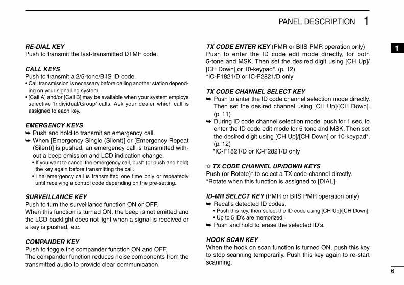
RE-DIAL KEYPush to transmit the last-transmitted DTMF code.
CALL KEYSPush to transmit a 2/5-tone/BIIS ID code.•Calltransmissionisnecessarybeforecallinganotherstationdepend-
ing on your signalling system.•[CallA]and/or[CallB]maybeavailablewhenyoursystememploys
selective ‘Individual/Group’ calls. Ask your dealer which call is assigned to each key.
EMERGENCY KEYSPush and hold to transmit an emergency call. ➥
When [Emergency Single (Silent)] or [Emergency Repeat ➥
(Silent)] is pushed, an emergency call is transmitted with-out a beep emission and LCD indication change.
•Ifyouwanttocanceltheemergencycall,push(orpushandhold)the key again before transmitting the call.
•Theemergencycall is transmittedone timeonlyor repeatedlyuntil receiving a control code depending on the pre-setting.
SURVEILLANCE KEYPush to turn the surveillance function ON or OFF.When this function is turned ON, the beep is not emitted and the LCD backlight does not light when a signal is received or a key is pushed, etc.
COMPANDER KEYPush to toggle the compander function ON and OFF. The compander function reduces noise components from the transmitted audio to provide clear communication.
TX CODE ENTER KEY (PMR or BIIS PMR operation only)Push to enter the ID code edit mode directly, for both 5-tone and MSK. Then set the desired digit using [CH Up]/ [CH Down] or 10-keypad*. (p. 12)*IC-F1821/D or IC-F2821/D only
TX CODE CHANNEL SELECT KEY Push to enter the ID code channel selection mode directly. ➥
Then set the desired channel using [CH Up]/[CH Down]. (p. 11) During ID code channel selection mode, push for 1 sec. to ➥
enter the ID code edit mode for 5-tone and MSK. Then set the desired digit using [CH Up]/[CH Down] or 10-keypad*. (p. 12)
*IC-F1821/D or IC-F2821/D only
✩ TX CODE CHANNEL UP/DOWN KEYSPush (or Rotate)* to select a TX code channel directly.* Rotate when this function is assigned to [DIAL].
ID-MR SELECT KEY (PMR or BIIS PMR operation only)Recalls detected ID codes. ➥
•Push this key, then select the ID code using [CH Up]/[CH Down]. •Upto5ID’sarememorized.
Push and hold to erase the selected ID’s. ➥
HOOK SCAN KEYWhen the hook on scan function is turned ON, push this key to stop scanning temporarily. Push this key again to re-start scanning.
7
1 PANEL DESCRIPTION
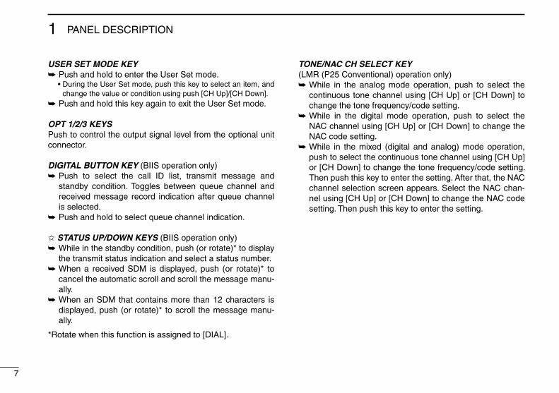
USER SET MODE KEY Push and hold to enter the User Set mode. ➥
•DuringtheUserSetmode,pushthiskeytoselectanitem,andchange the value or condition using push [CH Up]/[CH Down].
Push and hold this key again to exit the User Set mode. ➥
OPT 1/2/3 KEYSPush to control the output signal level from the optional unit connector.
DIGITAL BUTTON KEY (BIIS operation only) Push to select the call ID list, transmit message and ➥
standby condition. Toggles between queue channel and received message record indication after queue channel is selected.Push and hold to select queue channel indication. ➥
✩ STATUS UP/DOWN KEYS (BIIS operation only) While in the standby condition, push (or rotate)* to display ➥
the transmit status indication and select a status number. When a received SDM is displayed, push (or rotate)* to ➥
cancel the automatic scroll and scroll the message manu-ally. When an SDM that contains more than 12 characters is ➥
displayed, push (or rotate)* to scroll the message manu-ally.
* Rotate when this function is assigned to [DIAL].
TONE/NAC CH SELECT KEY(LMR (P25 Conventional) operation only)
While in the analog mode operation, push to select the ➥
continuous tone channel using [CH Up] or [CH Down] to change the tone frequency/code setting. While in the digital mode operation, push to select the ➥
NAC channel using [CH Up] or [CH Down] to change the NAC code setting. While in the mixed (digital and analog) mode operation, ➥
push to select the continuous tone channel using [CH Up] or [CH Down] to change the tone frequency/code setting. Then push this key to enter the setting. After that, the NAC channel selection screen appears. Select the NAC chan-nel using [CH Up] or [CH Down] to change the NAC code setting. Then push this key to enter the setting.

8
1PANEL DESCRIPTION
12345678910111213141516
SCRAMBLER/ENCRYPTION KEY(LMR (P25 Conventional) operation only)
While in the analog mode operation, push to toggle the ➥
voice scrambler function ON and OFF. While in the digital mode operation, push to toggle the en- ➥
cryption transmission function ON and OFF. While in the mixed (digital and analog) mode operation, ➥
push to toggle the voice scrambler and encryption trans-mission functions ON and OFF, separately or simultane-ously as below.
Voice scrambler function ON
Voice scrambler and Encryption transmittion functions ON
Voice scrambler and Encryption transmittion functions OFF
Encryption transmittion function ONPUSH
PUSH
PUSH
PUSH
( appears)
( appears)
( appears)
( disappears)
D For Digital mode operation onlyINDIVIDUAL KEY
Push to enter the individual ID code selection mode directly. ➥
Then select the desired individual ID code using [CH Up]/ [CH Down]. (p. 13) Push to stop the beep emission when receiving a matched ➥
individual ID code.
TALKGROUP KEY Push to enter the talkgroup ID code selection mode directly. ➥
Then select the desired talkgroup ID code using [CH Up]/ [CH Down]. (p. 13) Push to stop the beep emission when receiving a matched ➥
talkgroup ID code.
ZEROIZE KEYPush and hold to zeroize the encryption key data, programmed by the FS-F70/F1700 flash loader.
ENCRYPTION KEYPush to toggle the encryption transmission function ON or OFF.When this function is turned ON, “ ” appears on the function display.
9
2 BASIC OPERATION
Turning power ON ■
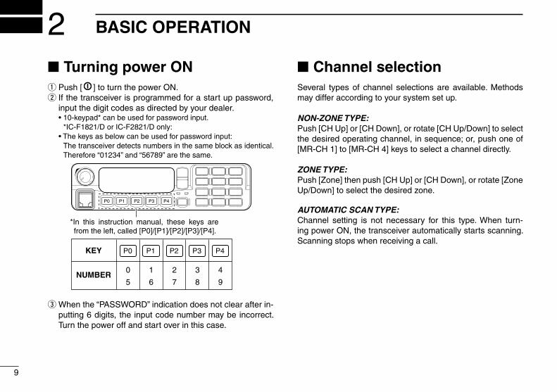
Push [ q ] to turn the power ON. If the transceiver is programmed for a start up password, w
input the digit codes as directed by your dealer. •10-keypad*canbeusedforpasswordinput.
*IC-F1821/D or IC-F2821/D only: •Thekeysasbelowcanbeusedforpasswordinput: The transceiver detects numbers in the same block as identical.
Therefore “01234” and “56789” are the same.
KEY
NUMBER0
5
4
9
3
8
2
7
1
6
P0 P4P3P2P1
P0 P4P3P2P1
*In this instruction manual, these keys are from the left, called [P0]/[P1]/[P2]/[P3]/[P4].
When the “PASSWORD” indication does not clear after in- e
putting 6 digits, the input code number may be incorrect. Turn the power off and start over in this case.
Channel selection ■
Several types of channel selections are available. Methods may differ according to your system set up.
NON-ZONE TYPE:Push [CH Up] or [CH Down], or rotate [CH Up/Down] to select thedesiredoperatingchannel,insequence;or,pushoneof[MR-CH 1] to [MR-CH 4] keys to select a channel directly.
ZONE TYPE:Push [Zone] then push [CH Up] or [CH Down], or rotate [Zone Up/Down] to select the desired zone.
AUTOMATIC SCAN TYPE:Channel setting is not necessary for this type. When turn-ing power ON, the transceiver automatically starts scanning. Scanning stops when receiving a call.

10
2BASIC OPERATION
12345678910111213141516
Call procedure ■
When your system employs tone signaling (excluding CTCSS and DTCS), the call procedure may be necessary prior to voice transmission. The tone signalling employed may be a selective calling system which allows you to call specific station(s) only and prevent unwanted stations from contacting you.
Select the desired TX code channel, 2/5-tone code, Indi- q
vidual ID code* or Talkgroup ID code* according to your System Operator’s instructions.
•Thismaynotbenecessarydependingonprogramming. •Refertopages11–13forselection. *Digital mode operation only.
Push the call key (assigned to one of the dealer programma- w
blekeys;exceptfortheDigitalmodeoperation)or[PTT]. After transmitting, the remainder of your communication e
can be carried out in the normal fashion.Selective calling Non-selective calling
Receiving and transmitting ■
Receiving:Push [ q ] to turn the power ON. Push [CH Up] or [CH Down], or rotate [CH Up/Down] to w
select a channel, in sequence. When receiving a call, adjust the audio output level to a e
comfortable listening level.
Transmitting:Wait for the channel to become clear to avoid interference.
Take the microphone off hook. q •2-tone,5-tonemutemaybereleased.(The‘audible’conditionis
selected and BUSY indicator lights green.) •Aprioritychannelmaybeselectedautomatically.
Wait for the channel to become clear. w •ThechannelisbusywhenBUSYindicatorlightsgreen.
Push [CALL] when initiating a call from your side. e •Codedaudiomaybeheardfromthetransceiver,then“ ” ap-
pears. •Thisoperationmaynotbenecessarydependingonyoursignal-
ing system. Ask your dealer for details. While pushing and holding [PTT], speak into the micro- r
phone at your normal voice level.Release [PTT] to receive. t
IMPORTANT:Tomaximizethereadabilityofyoursignal;1. Pause briefly after pushing [PTT].2. Hold the microphone 5 to 10 cm (2 to 4 inches) from
your mouth, then speak into the microphone at a normal voice level.
11
2 BASIC OPERATION
Receiving and transmitting (Continued) ■
Transmitting notes D• Transmit inhibit functionThe transceiver has several inhibit functions which restrict transmission under the following conditions:
-The channel is in mute condition (‘Inaudible’ condition; “ ” does not appear.)
- The channel is busy.- Un-matched (or matched) CTCSS is received. (Depending on the pre-setting)- Un-matched (or matched) NAC is received.* (Depending on the pre-setting)- The selected channel is a ‘receive only’ channel.*Digital mode operation only.
• Time-out timerAfter continuous transmission for the pre-programmed time period, the time-out timer is activated, causing the transceiver to stop transmitting.
• Penalty timerOnce the time-out timer is activated, transmission is further inhibited for a period determined by the penalty timer.
TX code channel selection DIf the transceiver has [TX Code CH Select] assigned to it, the indication can be toggled between the operating channel number (or name) and TX code channel number (or name). When the TX code channel number (or name) is displayed, [CH Up]/[CH Down] selects the TX code channel.
USING [TX CODE CH SELECT] KEY: Push [TX Code CH Select]— a TX code channel number q
(or name) appears. Push [CH Up] or [CH Down], or rotate [CH Up/Down] to w
select the desired TX code channel. Push [Call] (or [PTT] during MSK operation) to transmit the e
selected TX code.
USING [TX CODE CH UP]/[TX CODE CH DOWN] KEY:If the transceiver has a [TX Code CH Up], [TX Code CH Down] or [TX Code CH Up/Down] key assignment, the pro-grammed TX code channel can be selected directly when pushed or rotated.
NOTE for PMR or BIIS PMR operation:•TheLCDindicationdoesnotchangewhentheoperating
channel number (or name) is displayed.•To check the selected TX code, push [TX Code CH Select].

12
2BASIC OPERATION
12345678910111213141516
D TX code number edit (PMR or BIIS PMR operation only)
If the transceiver has [TX Code CH Select] or [TX Code En-ter] assigned to it, TX code contents can be edited within the allowable digits.
USING [TX CODE CH SELECT] KEY: Push [TX Code CH Select] to enter the TX code channel q
selection mode. •SelectthedesiredchannelbeforeenteringtheTXcodechannel
selection mode if necessary. Push [TX Code CH Select] for 1 sec. to enter the TX code w
edit mode. Push [TX Code CH Select] to select the desired digit to e
be edited. •Thedigittobeeditedblinks.
Push [CH Up], [CH Down] or 10-keypad*, or rotate [CH Up/ r
Down] to set the desired digit. Push [TX Code CH Select] to set the digit. The digit to the t
right will blink automatically. •Whenthe10-keypad*isusedforsetting,thedigittotherightwill
blink automatically without pushing [TX Code CH Select].Repeat y r and t to input all allowable digits.Push [Call] or [PTT] to transmit the edited TX code. u
*IC-F1821/D or IC-F2821/D only
USING [TX CODE ENTER] KEY: Select the desired TX code channel via [TX Code CH q
Select]+[CH Up] or [CH Down], [TX Code CH Up], [TX Code CH Down] or [TX Code CH Up/Down]. Push [TX Code Enter] to enter the TX code edit mode. w
Push [TX Code Enter] to select the desired digit to be ed- e
ited. •Thedigittobeeditedblinks.
Push [CH Up], [CH Down] or 10-keypad*, or rotate [CH Up/ r
Down] to set the desired digit . Push [TX Code Enter] to set the digit. The digit to the right t
will blink automatically. •Whenthe10-keypad*isusedforsetting,thedigittotherightwill
blink automatically without pushing [TX Code CH Select].Repeat y r and t to input all allowable digits.Push [Call] or [PTT] to transmit the edited TX code. u
*IC-F1821/D or IC-F2821/D only

13
2 BASIC OPERATION
D Individual ID code selection (Digital mode operation only)If the transceiver has [Individual] assigned to it, the indication can be toggled between the operating channel number (or name) and Individual ID code (or name). When the Individual ID code (or name) is displayed, [CH Up], [CH Down] or [CH Up/Down] selects the desired Individual ID code.
Push [Individual]— an Individual ID code (or name) ap- q
pears. Push [CH Up] or [CH Down], or rotate [CH Up/Down] to w
select the desired Individual ID code.Push [PTT] to transmit the selected Individual ID code. e
Push [Individual]— cancels the selected Individual ID code r
(return to the pre-set Talkgroup ID code in the channel.)
D Talkgroup ID code selection (Digital mode operation only)If the transceiver has [Talkgroup] assigned to it, the indication can be toggled between the operating channel number (or name) and Talkgroup ID code (or name). When the Talkgroup ID code (or name) is displayed, [CH Up], [CH Down] or [CH Up/Down] selects the desired Talkgroup ID code.
Push [Talkgroup]— a Talkgroup ID code (or name) ap- q
pears. Push [CH Up] or [CH Down], or rotate [CH Up/Down] to w
select the desired Talkgroup ID code.Push [PTT] to transmit the selected Talkgroup ID code. e
Change the channel— cancels the selected Talkgroup ID r
code (return to the pre-set Talkgroup ID code in the chan-nel.)
D DTMF transmissionIf the transceiver has [DTMF Autodial] assigned to it, the automatic DTMF transmission function is available. Up to 8 DTMF channels are available.
TO SELECT A TX CODE:Push [DTMF Autodial]— a DTMF channel appears. q
Push [CH Up] or [CH Down], or rotate [CH Up/Down] to w
select the desired DTMF channel. Push [DTMF Autodial] to transmit the DTMF code in the e
selected DTMF channel.

14
2BASIC OPERATION
12345678910111213141516
User Set mode ■
The User Set mode allows you to set seldom-changed set-tings. If the transceiver has [User Set Mode] assigned to it, you can “customize” the transceiver operation to suit your preferences and operating style.
Entering the User Set mode: Push and hold [User Set Mode] to enter the User Set q
mode. Push [User Set Mode] several times to select the appro- w
priate item. Then, push [CH Up] or [CH Down] to set the desired level/condition.
•IntheUserSetmode,theselectableitemsarepresetbyyourdealer. The presetable items are Backlight, LCD Contrast, Beep, Beep Level, Ringer Level, SQL Level, AF Min Level, Mic Gain, Horn and System Info.
Push and hold [User Set Mode] again to exit the User Set e
mode.
Scrambler function ■
The voice scrambler function provides private communication between stations. The frequency inversion type is equipped to all versions, moreover, the optional Rolling or Non-rolling type can be available.
Push [Scrambler] to turn the scrambler function ON. q •“ ” appears.
Push [Scrambler] again to turn the scrambler function w
OFF. •“ ” disappears.
15
3 BIIS OPERATION
Default setting ■
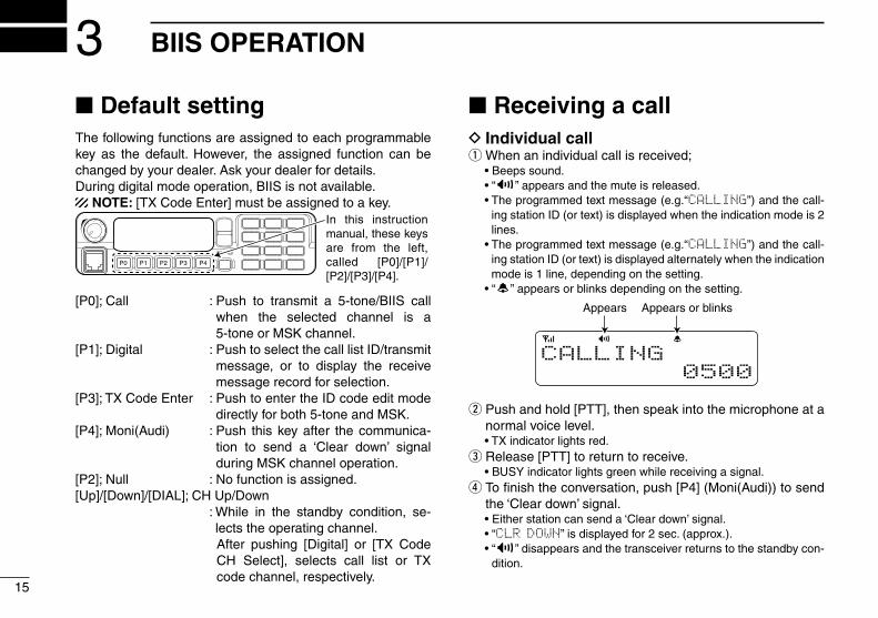
The following functions are assigned to each programmable key as the default. However, the assigned function can be changed by your dealer. Ask your dealer for details.During digital mode operation, BIIS is not available.
NOTE: [TX Code Enter] must be assigned to a key.
P0 P4P3P2P1
In this instruction manual, these keys are from the left, called [P0]/[P1]/ [P2]/[P3]/[P4].
[P0];Call :Push to transmit a 5-tone/BIIS callwhen the selected channel is a 5-tone or MSK channel.
[P1];Digital :PushtoselectthecalllistID/transmitmessage, or to display the receive message record for selection.
[P3];TXCodeEnter :PushtoentertheIDcodeeditmodedirectly for both 5-tone and MSK.
[P4];Moni(Audi) :Push thiskeyafter thecommunica-tion to send a ‘Clear down’ signal during MSK channel operation.
[P2];Null :Nofunctionisassigned.[Up]/[Down]/[DIAL];CHUp/Down : While in the standby condition, se-
lects the operating channel. After pushing [Digital] or [TX Code
CH Select], selects call list or TX code channel, respectively.
Receiving a call ■
Individual call DWhenanindividualcallisreceived; q
•Beepssound. •“ ” appears and the mute is released. •Theprogrammedtextmessage(e.g.“CALLING”) and the call-
ing station ID (or text) is displayed when the indication mode is 2 lines.
•Theprogrammedtextmessage(e.g.“CALLING”) and the call-ing station ID (or text) is displayed alternately when the indication mode is 1 line, depending on the setting.
•“ ” appears or blinks depending on the setting.
Appears or blinksAppears
CALLING0500
Push and hold [PTT], then speak into the microphone at a w
normal voice level. •TXindicatorlightsred.
Release [PTT] to return to receive. e •BUSYindicatorlightsgreenwhilereceivingasignal.
To finish the conversation, push [P4] (Moni(Audi)) to send r
the ‘Clear down’ signal. •Eitherstationcansenda‘Cleardown’signal. •“CLR DOWN” is displayed for 2 sec. (approx.). •“ ” disappears and the transceiver returns to the standby con-
dition.

16
3BIIS OPERATION
12345678910111213141516
Group call DWhenagroupcallisreceived; q
•Beepssound. •“ ” appears and the mute is released. •The programmed text message (e.g.“GROUP”) and the calling
station ID (or text) is displayed when the indication mode is 2 lines.
•Theprogrammed textmessage (e.g.“GROUP”) and the calling station ID (or text) is displayed alternately when the indication mode is 1 line, depending on the setting.
•“ ” appears or blinks depending on the setting.
Appears or blinksAppears
GROUP1120
Push and hold [PTT], then speak into the microphone at a w
normal voice level. •TXindicatorlightsred. NOTE: Only one station is permitted to speak.
Release [PTT] to return to receive. e •BUSYindicatorlightsgreenwhilereceivingasignal.
To finish the conversation, push [P4] (Moni(Audi)) to send r
the ‘Clear down’ signal. •Eitherstationcansenda‘Cleardown’signal. •“CLR DOWN” is displayed for 2 sec. (approx.) •“ ” disappears and the transceiver returns to the standby con-
dition.
Displaying the received call record D— Queue indication
The transceiver memorizes the calling station ID in the mem-ory. Up to 3 calls can be memorized, and the oldest call re-cord is erased when a 4th call is received. However, once the transceiver is powered OFF, the all records are cleared.
Push [P1] (Digital) for 1 sec. q •Displaysfollowingindication.
When a record is available
<QUEUE>-QUEUE!-
When no record is available
<QUEUE>NO QUEUE
Push [Up] or [Down], or rotate [DIAL] to select the desired w
call. Push [P1] (Digital) for 1 sec. again to return to the standby e
condition. •Whennooperationisperformedfor30sec.,thetransceiverre-
turns to the standby condition automatically.

17
3 BIIS OPERATION
Transmitting a call ■
A total of 3 ways for code selection are available—selecting the call code from memory, entering the call code from the keypad and calling back from the queue channel record.
Using call memory D While in the standby condition, push [P1] (Digital) to enter q
the call code memory channel selection mode. •“ ” appears.
CALLING0500
Appears
Push [Up] or [Down], or rotate [DIAL] to select the desired w
call code. Push [P0] (Call) or [PTT]* to call. e
*PTT call can be made only when PTT call capability is permitted.
NOTE: When no answer back is received, the trans-ceiver repeats the call 3 times (default) automatically, and “WAIT” is displayed during each call. However, an error beep sounds and “FAILED” is displayed when no answer back is received after the calls.
Push[PTT]totransmit;releasetoreceive. r
Push [P4] (Moni(Audi)) to send the ‘Clear down’ signal. t
Calling back from the queue channel D While in the standby condition, push [P1] (Digital) for 1 sec. q
to enter the queue memory channel selection mode. Push [Up] or [Down] or rotate [DIAL] to select the desired w
record.
<QUEUE>-QUEUE!-
Push [P0] (Call) or [PTT]* to call. e *PTT call can be made only when PTT call capability is permitted.
NOTE: When no answer back is received, the trans-ceiver repeats the call 3 times (default) automatically, and “WAIT” is displayed during each call. However, an error beep sounds and “FAILED” is displayed when no answer back is received after the calls.
Push[PTT]totransmit;releasetoreceive. r
Push [P4] (Moni(Audi)) to send the ‘Clear down’ signal. t

18
3BIIS OPERATION
12345678910111213141516
Direct code entry D While in the standby condition, push [P3] (TX Code Enter) q
to enter the TX code edit mode. •Codedigitforeditingblinks.
0500
Push [P3] (TX Code Enter) to select the desired digit to w
be edited. •Digitforeditingdiffersaccordingtothesetting.
Set the desired digit using [CH Up]/[CH Down]/[DIAL] or e
10-keypad*. *IC-F1821/D or IC-F2821/D only
Push [P3] (TX Code Enter) to set the digit, then the digit to r
the right will blink automatically. •Whenthe10-keypadisusedforsetting,thedigittotherightwill
blink automatically without pushing [P3] (TX Code Enter). Repeat t e and r to input all allowable digits. Push [P0] (Call) or [PTT]* to call. y
* PTT call can be made only when PTT call capability is permit-ted.
NOTE: When no answer back is received, the trans-ceiver repeats the call 3 times (default) automatically, and “WAIT” is displayed during each call. However, an error beep sounds and “FAILED” is displayed when no answer back is received after the calls.
Push[PTT]totransmit;releasetoreceive. u
Push [P4] (Moni(Audi)) to send the ‘Clear down’ signal. i
For your information When the “UpDate” setting for the call code is enabled, the set code is overwritten into the call code memory.

19
3 BIIS OPERATION
Receiving a message ■
Receiving a status message DWhenastatusmessageisreceived; q
•Beepssound. •Thecallingstation ID (or text)and thestatusmessage isdis-
played alternately when the indication mode is 1 line, depending on the setting.
RX Status 01BASE
Push [P4] (Moni(Audi)) to return to the standby condition. w
NOTE: Only the calling station ID (or text) is displayed (no message is displayed alternately) when the scroll timer is set to ‘OFF.’ In this case, push [Status Up]/[Sta-tus Down] to display the status message manually.
Receiving an SDM (Short Data Message) DWhenanSDMisreceived; q
•Beepssound. •ThecallingstationID(ortext)andtheSDMisdisplayedalter-
nately when the indication mode is 1 line, depending on the set-ting.
•“ ” appears.
SDM 8BASE
Appears
When the received SDM includes more than 12 charac- w
ters, the message scrolls automatically, when the auto-matic scroll function is activated.
•Push[StatusUp]/[StatusDown]toscrollthemessagemanually.
SDM 12345678BASE
Push [P4] (Moni(Audi)) to return to the standby condition. e

20
3BIIS OPERATION
12345678910111213141516
Received message selection DThe transceiver memorizes the received message in the memory. Up to 6 messages for status and SDM, or 95 charac-ter SDM’s can be memorized. The oldest message is erased when the 7th message is received. However, once the trans-ceiver is powered OFF, all messages are cleared.
Push [P1] (Digital) for 1 sec. q •Displaysqueuememory.
Push [P1] (Digital) momentarily. w •Displaysmessagememory.
When a message is available
MESSAGE- MSG! -
When no message is available
MESSAGE-NO MSG-
Push [Up] or [Down], or rotate [DIAL] to select the desired e
message. •WhenselectingtheSDMthatincludesmorethan12characters,
the message scrolls automatically when the automatic scroll function is activated.
•Push[StatusUp]/[StatusDown]toscrollthemessagemanually.
Push [P1] (Digital) for 1 sec. again to return to the standby r
condition. •Whennooperationisperformedfor30sec.,thetransceiverre-
turns to the standby condition automatically.

21
3 BIIS OPERATION
Transmitting a status ■
General DThe status message can be selected with the programmed text, and the message text is also displayed on the function display of the called station.Up to 24 status types (1 to 24) are available, and the status messages 22 and 24 have designated meanings.
Status 22: Emergency*Status 24: GPS request* The status 22 can also be used as a normal status message by disabling the designated meaning. However, the status 24 is fixed.
The status call can be sent with both individual and group calls.
Transmitting a status D While in the standby condition, push [P1] (Digital), then q
push [Up] or [Down], or rotate [DIAL] to select the desired station/group code. Push [P1] (Digital) again, then push [UP] or [DOWN] w to select the desired status message.
Or, you can select the desired status message using [Sta-tus Up]/[Status Down] key directly.
STATUS 01TX Status 01
Status message is displayed.
Push [P0] (Call) or [PTT]* to transmit the status message e
to the selected station/group. *PTT call can be made only when PTT call capability is permitted. •2beepswill soundand the transceiver returns to thestandby
condition automatically when the transmission is successful.

22
3BIIS OPERATION
12345678910111213141516
General DThe short data message, SDM, can be sent to an individual station or group stations. Also, 8 SDM memory channels are available and the messages can be edited via PC program-ming.
Transmitting an SDM D While in the standby condition, push [P1] (Digital), then q
push [Up] or [Down] or rotate [DIAL] to select the desired station/group code. Push [P1] (Digital) again, then push [Up] or [Down] or ro- w
tate [DIAL] to select the desired SDM.
Or, you can select the desired SDM using [Status Up]/ [Status Down] key directly.
MESSAGE 1SDM 1
SDM is displayed.
Appears
Push [P0] (Call) or [PTT]* to transmit the SDM to the se- e
lected station/group. *PTT call can be made only when PTT call capability is permitted. •2beepswill soundand the transceiver returns to thestandby
condition automatically when the transmission is successful.
Transmitting an SDM ■ (Short Data Message)

23
3 BIIS OPERATION
Programming an SDM memory D(IC-F1821/D or IC-F2821/D only) During standby condition, push [P1] (Digital) twice, then q
push [Up] or [Down] to select the desired SDM to be ed-ited.Push [ w M] or [#] to enter the message editing condition.
•Thefirstcharacterblinkswhen[#]ispushed,thelastcharacterblinks when [M] is pushed.
•“ ” blinks.
MESSAGE 8SDM 8
BlinksBlinks
When [#] is pushed.
Push the appropriate digit key, [0] to [9], to enter the de- e
sired character. •Seethetableatrightfortheavailablecharacters. •Pushing [UP]alsoentersspace,pushing [DOWN]deletes the
selected character. Push [#] to move the cursor to the right, push [ r M] to move the cursor to the left.Repeat steps t e and r to set the desired text message. Push [P1] (Digital) for 1 sec. to overwrite the set content y
into the memory. •Push[P1](Digital)momentarilytocanceltheeditingandreturn
to the original message indication.
• Available characters
Key
[0][1][2][3][4][5][6][7][8][9]
Characters
0 ! ? ' " , ; : _ ( ) < > [ ]
1 (space) # * / + - = & % $ @ ^
2 A B C a b c
3 D E F d e f
4 G H I g h i
5 J K L j k l
6 M N O m n o
7 P Q R S p q r s
8 T U V t u v
9 W X Y Z w x y z
/!
NOTE: A decimal point can only be written with the CS-F70/F1700 cloning software. Pre-programmed charac-ters can be rewritten with the 10-keypad, except for the decimal point, as it is not included in the transceiver char-acter list, and cannot be displayed again.

24
3BIIS OPERATION
12345678910111213141516
Position data transmission ■
When the optional cable and a GPS receiver is connected to the transceiver, the position (longitude and latitude) data can be transmitted automatically.Ask your dealer or system operator for connection details.
Thepositiondataistransmittedwhen;•Status24messageisreceived *When the status 24 message, GPS request, is received.•Fullyautomatic When automatic position transmission is enabled, send
the position data according to ‘Time Marker’ and ‘Interval Timer’ settings.
•PTTisreleased When ‘Send with Logoff’ is enabled. - Set the ‘Log-In/Off’ item as ‘L-OFF.’•Aftersendingastatusmessage When ‘Send with Status’ is enabled.•AftersendinganSDM When ‘Send with SDM’ is enabled.•Aftersendingstatus22(Emergency) When ‘Send with Emergency’ is enabled.
Printer connection ■
When the optional OPC-617 acc cable is connected to the transceiver, a printer can be connected to print out the received SDM content and the ID of the station who sent the message.Ask your dealer or system operator for connection details.
Digital ANI ■
The own ID can be transmitted each time the PTT is pushed (log-in) or released (log-off) during individual or group call communications.By receiving the ANI, the communication log can be recorded when using a PC dispatch application.
In addition, when using the ANI with log-in, the PTT side tone function can be used to inform you that the ID is sent and voice communication can be performed.
Auto emergency transmission ■
When [Emergency Single (Silent)] or [Emergency Repeat (Si-lent)] is pushed, an emergency signal is automatically trans-mitted for the specified time period.
The status 22 (Emergency) is sent to the selected ID station, and the position data is transmitted after the emergency sig-nal when a GPS receiver is connected to the transceiver.
The emergency transmission is performed on the emergency channel, however, when no emergency channel is specified, the signal is transmitted on the previously selected channel.
There is no change in the function display or beep emission during automatic emergency transmission.
25
3 BIIS OPERATION
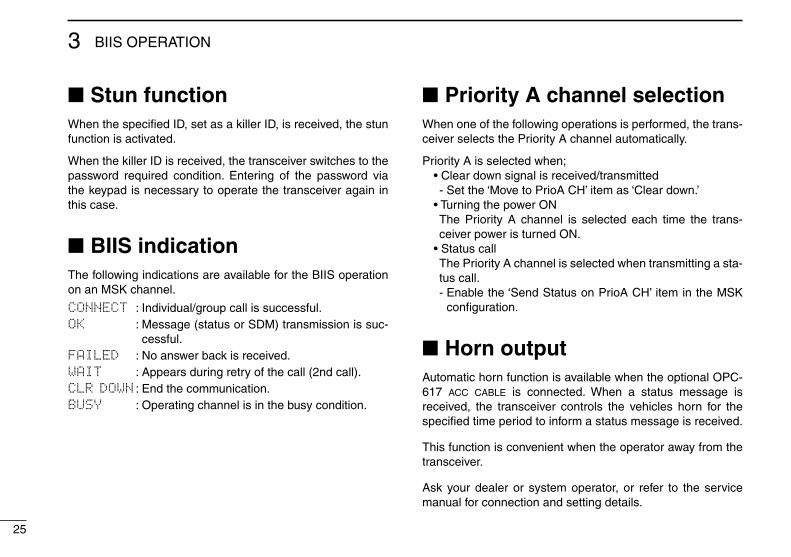
Stun function ■
When the specified ID, set as a killer ID, is received, the stun function is activated.
When the killer ID is received, the transceiver switches to the password required condition. Entering of the password via the keypad is necessary to operate the transceiver again in this case.
BIIS indication ■
The following indications are available for the BIIS operation on an MSK channel.
CONNECT : Individual/group call is successful.OK : Message (status or SDM) transmission is suc-
cessful.FAILED : No answer back is received.WAIT : Appears during retry of the call (2nd call).CLR DOWN : End the communication.BUSY : Operating channel is in the busy condition.
Priority A channel selection ■
When one of the following operations is performed, the trans-ceiver selects the Priority A channel automatically.
PriorityAisselectedwhen;•Cleardownsignalisreceived/transmitted - Set the ‘Move to PrioA CH’ item as ‘Clear down.’•TurningthepowerON The Priority A channel is selected each time the trans-ceiver power is turned ON.
•Statuscall The Priority A channel is selected when transmitting a sta-tus call.
- Enable the ‘Send Status on PrioA CH’ item in the MSK configuration.
Horn output ■
Automatic horn function is available when the optional OPC-617 acc cable is connected. When a status message is received, the transceiver controls the vehicles horn for the specified time period to inform a status message is received.
This function is convenient when the operator away from the transceiver.
Ask your dealer or system operator, or refer to the service manual for connection and setting details.

26
4CONNECTION AND MAINTENANCE
12345678910111213141516
t
Antennaq ANTENNA CONNECTOR
Connects to an antenna. Contact your dealer about antenna selection and placement.
qew
e EXTERNAL SPEAKER JACK
w Reserved for a future function.
Connect a 4–8 ø external speaker.
t OPTIONAL CABLE (OPC-617)Connect an external modem unit, dimmer control, etc.
Supplied speaker(IC-F1821/D or IC-F2821/D only. IC-F1721/D and IC-F2721/D has a built-in speaker.)
r
r MICROPHONE HANGERThe supplied self ground microphone can be used for the microphone on-hook and off-hook functions.(See p. 2)
Purchase separately
Connect the supplied micro-phone hanger to the ground level with wire for using the mi-crophone on-hook and off-hook functions.
When the optional micro-phone (HM-152/T) is used:
Black
Red
12VBattery
y
NOTE: Use the terminals as shown below for the cable connections.
SolderCrimp
R WARNING! NEVER remove the fuse-holder from the DC power cable.
y DC POWER RECEPTACLEConnects to a 12 V DC battery. Pay attention to polarities.
R WARNING! NEVER connect to a 24 V battery. This could damage the transceiver.
Rear panel connection ■

27
4 CONNECTION AND MAINTENANCE
Supplied Accessories ■
KEY-STICKER
Microphone Microphone hanger and screw set
DC power cable
Mounting bracket
Key caps
Function name stickers
Flat washers
Spring washers
Bracket bolts
Mounting screws (M5×12)
Self-tapping screws (M5×16)
Nuts
Speaker(Depending on version)
• Function name stickersThere are no names on the programmable function keys since the functions can be freely assigned to these keys.Attach the supplied function name stickers as below to the appropriate keys for easy recognition of that key’s assigned function.Then, protect the attached stickers from unsticking with the supplied key cap as below.
Function name sticker
Key cap

28
4CONNECTION AND MAINTENANCE
12345678910111213141516
Mounting the transceiver ■
The universal mounting bracket supplied with your transceiv-er allows overhead mounting.•Mountthetransceiversecurelywiththe4suppliedscrewsto
a thick surface which can support more than 1.5 kg.
Nut
*Felts reduce the vibration effects.
Felt*
Felt*
Flat washer
Spring washer
When usingself-tapping screws
Optional OPC-617 installation ■
Install the OPC-617 as shown below.
OPC-617
Cut off the bushing as in the illustration, when you install the optional OPC-617.
q Dimmer cont. INw AF OUTe Det. AF OUT r Mod. INt PTT control IN or
y Horn drive cont. OUTu AF GNDi Det. AF GNDo Mod. GND
OPTIONAL CABLE PIN ASSIGNMENT
t r e w q
o i u y FTSW control IN

29
4 CONNECTION AND MAINTENANCE
Install the optional UT-109 or UT-110 unit as follows:
Turn the power OFF, then disconnect the DC power cable. q
Unscrew the 4 cover screws, then remove the bottom w
cover. Cut the pattern on the PCB at the TX mic circuit (MIC) e
and RX AF circuit (AF OUT), then solder CP37 as shown below.
FRONTFRONTMIC and AF OUT
CP37
Install the unit as shown in the diagram below. r
FRONTFRONT
Replace the bottom cover and screws, then re-connect the t
DC power cable.
Un-solder
Re-solder
Remove
NOTE: When uninstall-ing the unitBe sure to re-solder the disconnected points and un-solder the connected points as above when you remove the unit. Oth-erwise no TX modulation or AF output is available.
Optional UT-109 or UT-110 installation ■

30
4CONNECTION AND MAINTENANCE
12345678910111213141516
Antenna ■
A key element in the performance of any communication sys-tem is an antenna. Contact your dealer about antennas and the best places to mount them.
Fuse replacement ■
A fuse is installed in the supplied DC power cable. If a fuse blows or the transceiver stops functioning, track down the source of the problem if possible, and replace the damaged fuse with a new rated one.❑ Fuse rating: 20 A USE the 20 A fuse only.
Cleaning ■
If the transceiver becomes dusty or dirty, wipe it clean with a soft, dry cloth.
AVOID using solvents such as benzene or alcohol, as they may damage the transceiver surfaces.
Options ■•RMK-2 separation kit +
OPC-607/OPC-608/OPC-609 separation cables
Allows you to install the transceiver main unit separately from the front panel for operating convenience.
•SP-5/SP-10/SP-22/SP-30/SP-35 external speakers
Input impedance : 4 ø Max. input power : 6 W (SP-5)/5 W (SP-10)/
7 W (SP-22/SP-35)/30W (SP-30) SP-5 : Large speaker for good audio quality. SP-10 : For all-round mobile operation. SP-22/SP-35 : Compact and easy-to-install. SP-30 : High input power level.
•HM-152/HM-152T/HM-148G/HM-148T hand microphones
HM-152 : Hand microphone HM-152T : DTMF microphone HM-148G : Self ground heavy duty microphone HM-148T : Self ground heavy duty DTMF microphone The 10-keypad of this microphone can be used for the
DTMF code transmission only.
•SM-25 desktop microphone
• UT-109 (#02)/UT-110 (#02) scrambler units
Non-rolling type (UT-109)/Rolling type (UT-110) voice scrambler unit provides higher communication security.
•OPC-617 acc cable
Allows you to connect to an external terminal.
Some options may not be available in some countries. Please ask your dealer for details.

31
5 SAFETY TRAINING INFORMATION
W ARNING
Your Icom radio generates RF electromagnetic en-ergy during transmit mode. This radio is designed for and classified as “Occupational Use Only”, meaning it must be used only during the course of employment by individuals aware of the hazards, and the ways to minimize such hazards. This radio
is NOT intended for use by the “General Population” in an uncon-trolled environment.
•ForcompliancewithFCCandIndustryCanadaRFExposureRe-quirements, the transmitter antenna installation shall comply with the following two conditions:
1. The transmitter antenna gain shall not exceed 0 dBi. 2. IC-F1721/IC-F1721D/IC-F1821/IC-F1821D: The antenna is required to be located outside of a vehicle and
kept at a distance of 48 centimeters or more between the trans-mitting antenna of this device and any persons during operation. For small vehicle as worst case, the antenna shall be located on the roof top at any place on the centre line along the vehicle in order to achieve 48 centimeters separation distance. In order to ensure this distance is met, the installation of the antenna must be mounted at least 48 centimeters away from the nearest edge of the vehicle in order to protect against exposure to bystanders.
2. IC-F2721/IC-F2721D/IC-F2821/IC-F2821D: The antenna is required to be located outside of a vehicle and
kept at a distance of 38 centimeters or more between the trans-mitting antenna of this device and any persons during operation. For small vehicle as worst case, the antenna shall be located on the roof top at any place on the centre line along the vehicle in order to achieve 38 centimeters separation distance. In order to ensure this distance is met, the installation of the antenna must be mounted at least 38 centimeters away from the nearest edge of the vehicle in order to protect against exposure to bystanders.
3. IC-F1721/IC-F1721D/IC-F1821/IC-F1821D: Transmit only when people outside the vehicle are at least the
recommended minimum distance of 100 centimeters away from the properly installed antenna. This separation distance will en-sure that there is sufficient distance from a properly installed externally-mounted antenna to satisfy the RF exposure require-ments in the applicable RF exposure compliance standards.
3. IC-F2721/IC-F2721D/IC-F2821/IC-F2821D: Transmit only when people outside the vehicle are at least the
recommended minimum distance of 82 centimeters away from the properly installed antenna. This separation distance will en-sure that there is sufficient distance from a properly installed externally-mounted antenna to satisfy the RF exposure require-ments in the applicable RF exposure compliance standards.
32
5SAFETY TRAINING INFORMATION
12345678910111213141516
CAUTION
To ensure that your exposure to RF electromag-netic energy is within the FCC allowable limits for occupational use, always adhere to the fol-lowing guidelines:
•DO NOT operate the radio without a proper antenna attached, as this may damage the radio and may also cause you to exceed FCC RF exposure limits. A proper antenna is the antenna supplied with this radio by the manufacturer or an antenna specifically authorized by the manufacturer for use with this radio.
•DO NOT transmit for more than 50% of total radio use time (“50% duty cycle”). Transmitting more than 50% of the time can cause FCC RF exposure compliance requirements to be exceeded. The radio is transmitting when the “TX indicator” lights red. You can cause the radio to transmit by pressing the “PTT” switch.
Electromagnetic Interference/CompatibilityDuring transmissions, your Icom radio generates RF energy that can possibly cause interference with other devices or systems. To avoid such interference, turn off the radio in areas where signs are posted to do so. DO NOT operate the transmitter in areas that are sensitive to electromagnetic radiation such as hospitals, aircraft, and blasting sites.
33
5 SAFETY TRAINING INFORMATION
Votre radio Icom produit une énergie électro-magnétique de radiofréquences (RF), en mode de transmission. Cette radio est conçue pour un «usage professionnel seulement» et clas-sée comme tel, ce qui signifie qu'elle doit être utilisée uniquement dans le cadre d'un travail
par des personnes conscientes des dangers et des mesures visant à minimiser ces dangers. Elle N'EST PAS conçue pour une «utilisation grand public», dans un environnement non con-trôlé.
•Afindesatisfaireauxexigencesde laFCCetd'IndustrieCanadaenmatièred'expositionauxRF,ilestnécessairequel'antennesoitinstalléeconformémentauxdeuxconditionssuivantes:
1.Le gain de l'antenne du radio émetteur ne doit pas dépasser 0 dBi.
2. IC-F1721/IC-F1721D/IC-F1821/IC-F1821D: Il faut que l'antenne émettrice de cet appareil soit placée à
l'extérieur d'un véhicule et tenue éloignée d'au moins 48 cen-timètres de toute personne pendant le fonctionnement. Dans le piredescas,pourunpetitvéhicule,l'antennedoitêtreplacéesurletoit,n'importeoùdansl'axecentralduvéhicule,afinderespect-erunedistancede48cmdubordleplusrapprochéduvéhiculeetainsiéviterquelespersonnesprésentessoientexposées.
2. IC-F2721/IC-F2721D/IC-F2821/IC-F2821D: Il faut que l'antenne émettrice de cet appareil soit placée à
l'extérieur d'un véhicule et tenue éloignée d'au moins 38 cen-timètres de toute personne pendant le fonctionnement. Dans le piredescas,pourunpetitvéhicule,l'antennedoitêtreplacéesurletoit,n'importeoùdansl'axecentralduvéhicule,afinderespect-erunedistancede38cmdubordleplusrapprochéduvéhiculeetainsiéviterquelespersonnesprésentessoientexposées.
3. IC-F1721/IC-F1721D/IC-F1821/IC-F1821D: Émettreuniquementlorsquelespersonnesàl’extérieurduvéhi-
culesetrouventàaumoinsladistanceminimalerecommandéede100cmde l’antennecorrectement installée.Cettedistancedesécuritéassureraquelespersonnessoientplacéessuffisam-ment loin d’une antenne correctement fixée à l’extérieur poursatisfaire aux exigences en matière d’exposition aux RF, en vertu desnormesdeconformitéapplicables.
3. IC-F2721/IC-F2721D/IC-F2821/IC-F2821D: Émettreuniquementlorsquelespersonnesàl’extérieurduvéhi-
culesetrouventàaumoinsladistanceminimalerecommandéede82cmdel’antennecorrectementinstallée.Cettedistancedesécurité assurera que les personnes soient placées suffisam-ment loin d’une antenne correctement fixée à l’extérieur poursatisfaire aux exigences en matière d’exposition aux RF, en vertu desnormesdeconformitéapplicables.
A V E R T I S S E M E N T
34
5SAFETY TRAINING INFORMATION
12345678910111213141516
MISE EN GARDE
Afin de vous assurer que votre exposition à une énergie électromagnétique de RF se situe dans les limites permises par la FCC pour une utilisation grand public, veuillez en tout temps respecter les directives suivantes:
•NEPASfairefonctionnerlaradiosansqu'uneantenneappropriéeysoitfixée,carcecirisqued'endommager laradioetcauseruneexpositionsupérieureauxlimitesétabliesparlaFCC.L'antenneap-propriéeestcellequiest fournieaveccetteradiopar le fabricantouuneantennespécialementautoriséepar lefabricantpourêtreutiliséeaveccetteradio.
•NEPASémettrependantplusde50%dutempstotald'utilisationdel'appareil(«50%dufacteurd'utilisation»).Émettrependantplusde50%dutempstotald'utilisationpeutcauseruneexpositionauxRFsupérieureauxlimitesétabliesparlaFCC.LorsquelevoyantDELrouges’allume,cetteradioestentraind’émettre.Laradioémettrasi vous appuyez sur le bouton du microphone.
Interférence électromagnétique et compatibilitéEnmodede transmission,votreradio Icomproduitde l'énergiedeRFquipeutprovoquerdesinterférencesavecd'autresappareilsousystèmes. Pour éviter de telles interférences, mettez la radio horstensiondanslessecteursoùunesignalisationl’exige.NEPASfairefonctionnerl'émetteurdansdessecteurssensiblesaurayonnementélectromagnétiquetelsqueleshôpitaux,lesaéronefsetlessitesdedynamitage.

1-1-32 Kamiminami, Hirano-ku, Osaka 547-0003, Japan
A-6406H-1EX-yPrinted in Japan© 2004–2012 Icom Inc.
Printed on recycled paper with soy ink.