Embed Size (px)
Citation preview

IC Engine Combustion Simulation Report
file:///C|/Users/fy337/Dropbox/career/CFD%20Projects/Ic%20engine%20sector%20combustion/Report.html[11/8/2016 5:06:51 PM]
Title
IC Engine Combustion Simulation Report
Date
2016/08/23 08:50:55
Contents1. File Report Table 1 File Information for ICE2. Mesh Report Table 2 Mesh Information for ICE Table 3 Cell count at crank angles3. Setup 3.1. Physics Table 4 Boundary Conditions 3.2. Relaxations Table 5 Relaxations at crank angles 3.3. Dynamic Mesh Setup Table 6 Dynamic Mesh Events 3.4. IC Engine System Inputs4. Solution Data 4.1. Animation: mesh-on-ice_cutplane_1 4.2. Animation: pt-temperature on ice-cyl-chamber-bottom, ice-cyl-chamber-top, ice-cyl-piston, ice-piston, ice-sector-top-faces 4.3. Animation: pt-velocity-magnitude on ice-cyl-chamber-bottom, ice-cyl-chamber-top, ice-cyl-piston, ice-piston, ice-sector-top-faces 4.4. Animation: temperature on ice_cutplane_1 4.5. Animation: velocity-magnitude on ice_cutplane_1 4.6. Table: mesh-on-ice_cutplane_1 4.7. Table: pt-temperature on ice-cyl-chamber-bottom, ice-cyl-chamber-top, ice-cyl-piston, ice-piston, ice-sector-top-faces 4.8. Table: pt-velocity-magnitude on ice-cyl-chamber-bottom, ice-cyl-chamber-top, ice-cyl-piston, ice-piston, ice-sector-top-faces 4.9. Table: temperature on ice_cutplane_1 4.10. Table: velocity-magnitude on ice_cutplane_1 4.11. Charts Chart 1 Swirl Ratio Chart 2 Tumble Ratio Chart 3 Cross Tumble Ratio Chart 4 Apparent Heat Release Rate on (ice-fluid-chamber-bottom ice-fluid-chamber-top ice-fluid-piston) Chart 5 Number of Iterations per Time Step Chart 6 Monitor: Mass-Average Turbulent Kinetic Energy (k) (ice-fluid-piston ice-fluid-chamber-top ice-fluid-chamber-bottom) Chart 7 Monitor: Volume Integral Density (ice-fluid-piston ice-fluid-chamber-top ice-fluid-chamber-bottom) Chart 8 Monitor: Max Static Pressure (ice-fluid-piston ice-fluid-chamber-top ice-fluid-chamber-bottom) Chart 9 Monitor: Max Static Temperature (ice-fluid-piston ice-fluid-chamber-top ice-fluid-chamber-bottom) Chart 10 Monitor: Max Velocity Magnitude (ice-fluid-piston ice-fluid-chamber-top ice-fluid-chamber-bottom) Chart 11 Penetration length of injection-0 per Time Step Chart 12 Monitor: Volume-Average Static Pressure (ice-fluid-piston ice-fluid-chamber-top ice-fluid-chamber-bottom) Chart 13 Monitor: Volume Integral Static Temperature (ice-fluid-piston ice-fluid-chamber-top ice-fluid-chamber-bottom) Chart 14 Monitor: Volume (ice-fluid-piston ice-fluid-chamber-top ice-fluid-chamber-bottom)
1. File ReportTable 1. File Information for ICE
Case ICE
File Path C:\Users\fy337\Documents\IC engine simulations\Test sector combustion\sector combustion_files\dp0\ICE\Fluent\ICE-1-01476.dat.gz
File Date 23 August 2016
File Time 08:49:20 AM

IC Engine Combustion Simulation Report
file:///C|/Users/fy337/Dropbox/career/CFD%20Projects/Ic%20engine%20sector%20combustion/Report.html[11/8/2016 5:06:51 PM]
File Type FLUENT
File Version 15.0.0
2. Mesh ReportTable 2. Mesh Information for ICE
Domain Nodes Elementsice fluid chamber bottom 470654 450570
ice fluid chamber top 13544 9795
ice fluid piston 73402 66443
All Domains 557600 526808 Table 3. Cell count at crank anglesCrank Angle Cell Count0.000e+00 8.930e+04
3. Setup
3.1. PhysicsTable 4. Boundary ConditionsType Zones Valueswall ice-cyl-chamber-bottom Temperature (k) 567
wall ice-cyl-chamber-top Temperature (k) 567
wall ice-cyl-piston Temperature (k) 567
wall ice-piston Temperature (k) 645
wall ice-sector-top-faces Temperature (k) 602
3.2. RelaxationsTable 5. Relaxations at crank anglesCrank Angle Pressure Density Body Forces Momentum Turbulent Kinetic Energy Turbulent Dissipation Rate Turbulent Viscosity Species Energy Discrete Phase Sources0.000 0.300 1.000 1.000 0.500 0.400 0.400 1.000 1.000 1.000 1.000
3.3. Dynamic Mesh SetupTable 6. Dynamic Mesh EventsAt Crank Angle (deg) Name Description721.000 reduce-dt-injection-0(0.05), enable-pt-cal-act-for-injection-0
747.500 increase-dt-injection-0(0.25), disable-pt-cal-act-for-injection-0
3.4. IC Engine System InputsEngine InputsEngine Speed (rev/min) : 1500Crank Radius (mm) : 55Piston Pin Offset/Wrench (mm) : 0Connecting Rod Length (mm) : 165-Journal CustomizationPre Iteration Journal File : N/A

IC Engine Combustion Simulation Report
file:///C|/Users/fy337/Dropbox/career/CFD%20Projects/Ic%20engine%20sector%20combustion/Report.html[11/8/2016 5:06:51 PM]
Post Iteration Journal File : N/A
4. Solution Data
4.1. Animation: mesh-on-ice_cutplane_1
4.2. Animation: pt-temperature on ice-cyl-chamber-bottom, ice-cyl-chamber-top, ice-cyl-piston, ice-piston,ice-sector-top-faces
IC Engine Combustion Simulation Report
file:///C|/Users/fy337/Dropbox/career/CFD%20Projects/Ic%20engine%20sector%20combustion/Report.html[11/8/2016 5:06:51 PM]
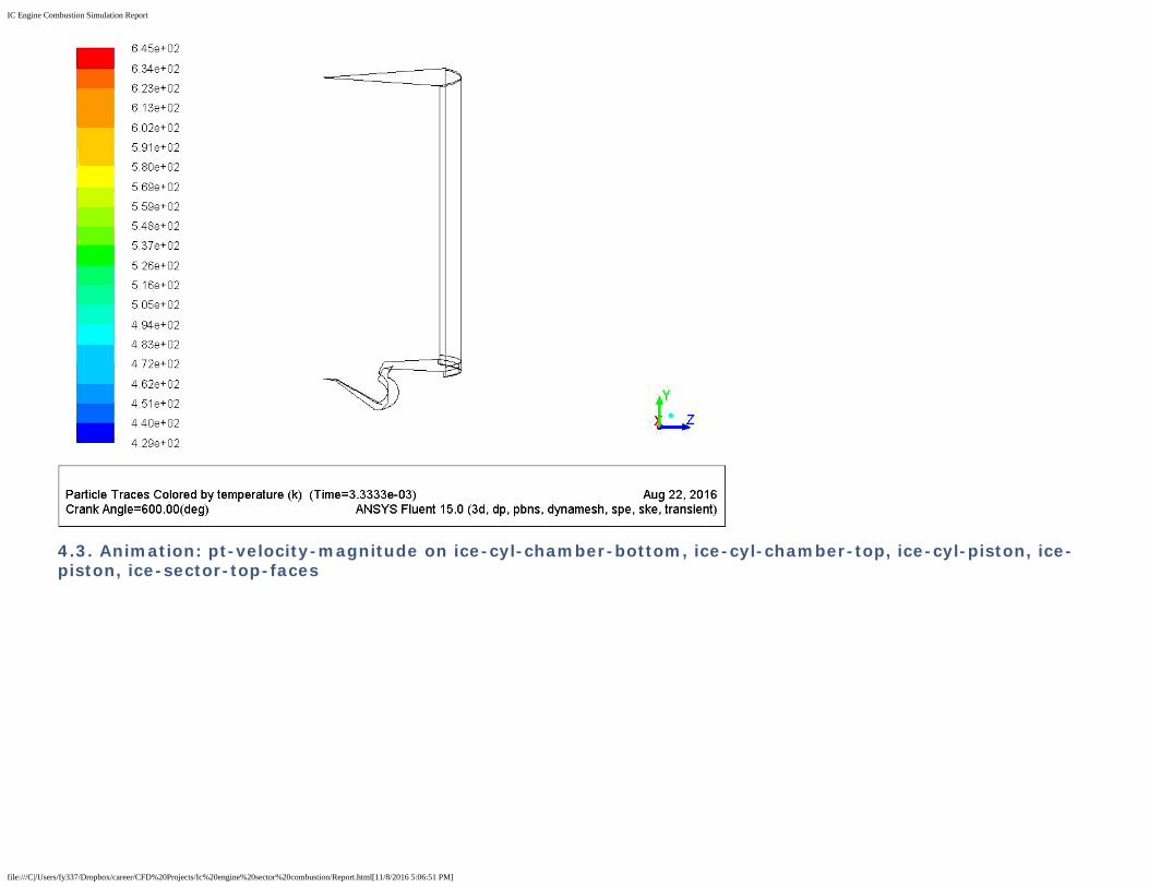
4.3. Animation: pt-velocity-magnitude on ice-cyl-chamber-bottom, ice-cyl-chamber-top, ice-cyl-piston, ice-piston, ice-sector-top-faces

IC Engine Combustion Simulation Report
file:///C|/Users/fy337/Dropbox/career/CFD%20Projects/Ic%20engine%20sector%20combustion/Report.html[11/8/2016 5:06:51 PM]
4.4. Animation: temperature on ice_cutplane_1

IC Engine Combustion Simulation Report
file:///C|/Users/fy337/Dropbox/career/CFD%20Projects/Ic%20engine%20sector%20combustion/Report.html[11/8/2016 5:06:51 PM]
4.5. Animation: velocity-magnitude on ice_cutplane_1

IC Engine Combustion Simulation Report
file:///C|/Users/fy337/Dropbox/career/CFD%20Projects/Ic%20engine%20sector%20combustion/Report.html[11/8/2016 5:06:51 PM]
4.6. Table: mesh-on-ice_cutplane_1

IC Engine Combustion Simulation Report
file:///C|/Users/fy337/Dropbox/career/CFD%20Projects/Ic%20engine%20sector%20combustion/Report.html[11/8/2016 5:06:51 PM]

IC Engine Combustion Simulation Report
file:///C|/Users/fy337/Dropbox/career/CFD%20Projects/Ic%20engine%20sector%20combustion/Report.html[11/8/2016 5:06:51 PM]
4.7. Table: pt-temperature on ice-cyl-chamber-bottom, ice-cyl-chamber-top, ice-cyl-piston, ice-piston, ice-sector-top-faces

IC Engine Combustion Simulation Report
file:///C|/Users/fy337/Dropbox/career/CFD%20Projects/Ic%20engine%20sector%20combustion/Report.html[11/8/2016 5:06:51 PM]
4.8. Table: pt-velocity-magnitude on ice-cyl-chamber-bottom, ice-cyl-chamber-top, ice-cyl-piston, ice-piston,

IC Engine Combustion Simulation Report
file:///C|/Users/fy337/Dropbox/career/CFD%20Projects/Ic%20engine%20sector%20combustion/Report.html[11/8/2016 5:06:51 PM]
ice-sector-top-faces
IC Engine Combustion Simulation Report
file:///C|/Users/fy337/Dropbox/career/CFD%20Projects/Ic%20engine%20sector%20combustion/Report.html[11/8/2016 5:06:51 PM]
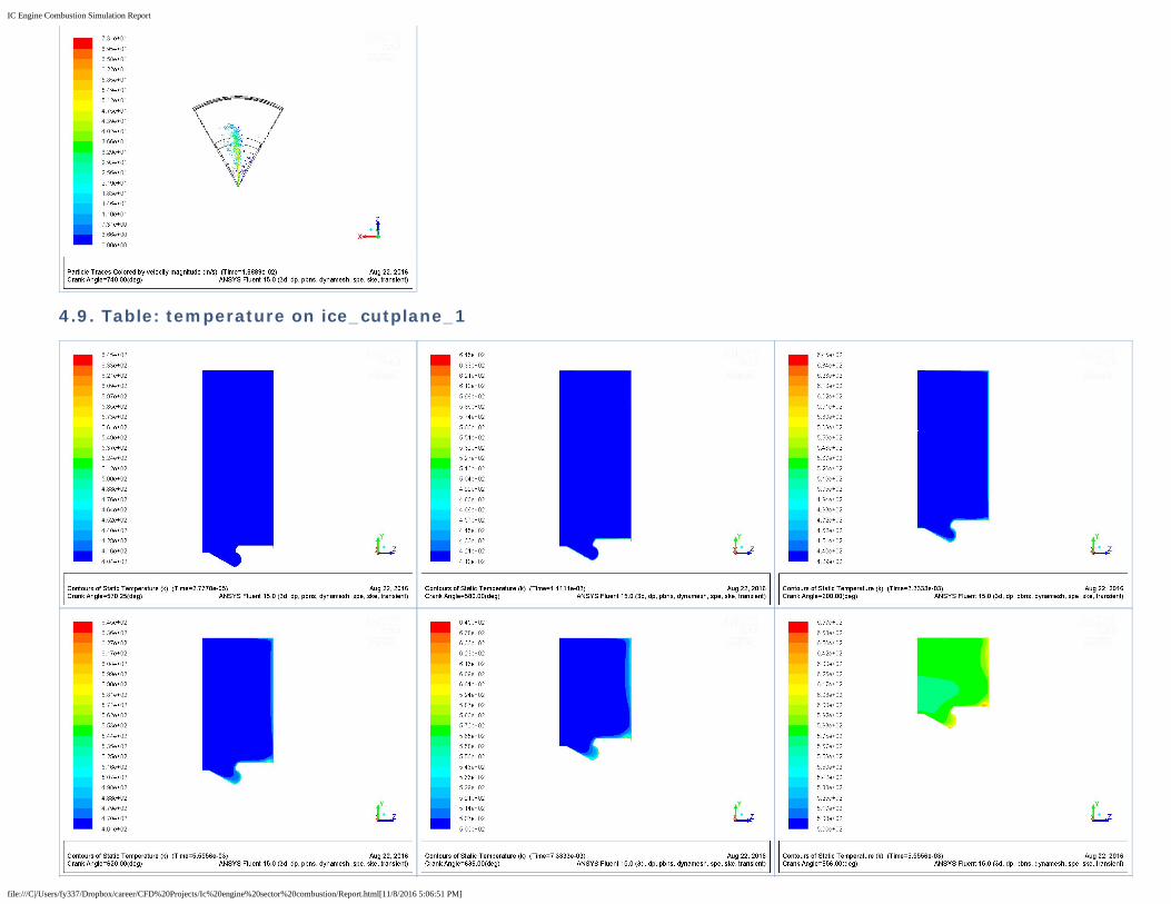
4.9. Table: temperature on ice_cutplane_1

IC Engine Combustion Simulation Report
file:///C|/Users/fy337/Dropbox/career/CFD%20Projects/Ic%20engine%20sector%20combustion/Report.html[11/8/2016 5:06:51 PM]
4.10. Table: velocity-magnitude on ice_cutplane_1

IC Engine Combustion Simulation Report
file:///C|/Users/fy337/Dropbox/career/CFD%20Projects/Ic%20engine%20sector%20combustion/Report.html[11/8/2016 5:06:51 PM]

IC Engine Combustion Simulation Report
file:///C|/Users/fy337/Dropbox/career/CFD%20Projects/Ic%20engine%20sector%20combustion/Report.html[11/8/2016 5:06:51 PM]
4.11. Charts
Chart 1. Swirl Ratio

IC Engine Combustion Simulation Report
file:///C|/Users/fy337/Dropbox/career/CFD%20Projects/Ic%20engine%20sector%20combustion/Report.html[11/8/2016 5:06:51 PM]
Chart 2. Tumble Ratio
Chart 3. Cross Tumble Ratio

IC Engine Combustion Simulation Report
file:///C|/Users/fy337/Dropbox/career/CFD%20Projects/Ic%20engine%20sector%20combustion/Report.html[11/8/2016 5:06:51 PM]
Chart 4. Apparent Heat Release Rate on (ice-fluid-chamber-bottom ice-fluid-chamber-top ice-fluid-piston)
Chart 5. Number of Iterations per Time Step
Chart 6. Monitor: Mass-Average Turbulent Kinetic Energy (k) (ice-fluid-piston ice-fluid-chamber-top ice-fluid-chamber-bottom)

IC Engine Combustion Simulation Report
file:///C|/Users/fy337/Dropbox/career/CFD%20Projects/Ic%20engine%20sector%20combustion/Report.html[11/8/2016 5:06:51 PM]
Chart 7. Monitor: Volume Integral Density (ice-fluid-piston ice-fluid-chamber-top ice-fluid-chamber-bottom)
Chart 8. Monitor: Max Static Pressure (ice-fluid-piston ice-fluid-chamber-top ice-fluid-chamber-bottom)

IC Engine Combustion Simulation Report
file:///C|/Users/fy337/Dropbox/career/CFD%20Projects/Ic%20engine%20sector%20combustion/Report.html[11/8/2016 5:06:51 PM]
Chart 9. Monitor: Max Static Temperature (ice-fluid-piston ice-fluid-chamber-top ice-fluid-chamber-bottom)
Chart 10. Monitor: Max Velocity Magnitude (ice-fluid-piston ice-fluid-chamber-top ice-fluid-chamber-bottom)
Chart 11. Penetration length of injection-0 per Time Step

IC Engine Combustion Simulation Report
file:///C|/Users/fy337/Dropbox/career/CFD%20Projects/Ic%20engine%20sector%20combustion/Report.html[11/8/2016 5:06:51 PM]
Chart 12. Monitor: Volume-Average Static Pressure (ice-fluid-piston ice-fluid-chamber-top ice-fluid-chamber-bottom)
Chart 13. Monitor: Volume Integral Static Temperature (ice-fluid-piston ice-fluid-chamber-top ice-fluid-chamber-bottom)

IC Engine Combustion Simulation Report
file:///C|/Users/fy337/Dropbox/career/CFD%20Projects/Ic%20engine%20sector%20combustion/Report.html[11/8/2016 5:06:51 PM]
Chart 14. Monitor: Volume (ice-fluid-piston ice-fluid-chamber-top ice-fluid-chamber-bottom)