Embed Size (px)
Citation preview

IBPS Hardware User’s Guide Rev 3.5, June 2008
Intelligent Battery and Power System™ HARDWARE USER’S GUIDE

Contents
Introduction Section 1 1.0 General System 1.1 Small System 1.2 Large System
Section 2
2.0 BB-XX, MP-XX, and XP-xx Battery Management Modules 2.1 Management Modules - Features 2.2 Management Modules – Operation 2.2.1 Battery Power (Discharging) 2.2.1.1. Calculating the Power Requirements 2.2.2 Battery Charging / External Power 2.3 LEDS 2.4 Configuring the Battery Management Modules 2.4.1 Connectors 2.4.1.1 Battery Connectors (J12, J17, J21, and J22) 2.4.1.2 External Power Connectors (J5 and J7) 2.4.1.3 Control and Status Connector (J1) 2.4.1.3.1 External switch 2.4.1.3.2 External power signal 2.4.1.3.2B Special considerations when connecting to a PC 2.4.1.3.3 Discharge status led 2.4.1.3.4 Charge status led 2.4.1.3.5 External LCD display 2.4.1.4 RS232 Port Connector (J8) 2.4.1.5 Test Connector (J9) 2.4.1.6 Expansion Connecter (J10)

2.4.1.7 System Power Connector (J13)
Section 3
3.0 Expansion Battery Management Module 3.1 Configuring 3.1.1 Connectors 3.1.1.1 Expansion Battery Connectors 3.1.1.2 External Power Connectors 3.1.1.3 Expansion Connector
Section 4
4.0 DC-023R Ultra-High Efficiency DC-DC Converter Module 4.1 Configuring the DC-023R 4.1.1 DC-023R Connectors 4.1.1.1 ATX Style Power Connector (J20) 4.1.1.2 Power Connector (J25) 4.1.1.3 Stacking Connector 5.0 DC-123S Ultra-High Efficiency DC-DC Converter Module
Section 5
5.0 Batteries 5.1 Battery Calibration 5.2 Backplanes 5.2.1 Backplane connectors
Section 6
6.0 Configuring complete systems / Getting started 6.1 Calculate your power requirements 6.2 Providing external power 6.3 Advanced Features 6.3.1 Advanced switch features 6.3.2 Advanced power control 6.3.3 Advanced monitoring features 6.3.4 Advanced display feature - LCD Display 6.4 Connecting to a PC motherboard... 6.5 Large System
Section 7 ~ Software
Section 8 ~ Debugging Customer Support Items

Introduction: The Intelligent Battery and Power System (IBPS) is a fully autonomous scalable power management system that manages all aspects of powering a system with battery power. It handles the power switching between battery power and power from an external supply along with all aspects regarding charging and discharging of the batteries. This allows you to power your system while charging your batteries at the same time. Key Features: - Fully autonomous, just hook it up and go - Fully configurable to meet specific needs of your system - Manages all aspects powering a system with battery power - Uses Smart Battery technology - Manages charging of batteries using almost any external power source from power supplies to solar panels - Switches power to load between external power and battery power. - Can simultaneously power system and charge batteries - Scales from 1 to 128 batteries - Hardware safety features - Host communication available via RS232 for monitoring status if desired - Two types of monitoring software to manage all the aspects of the battery power -Minibats is installed on a system powered by an IBPS system that performs power management similar to laptop computers - Fullbats can be installed on any system and can be used to monitor an IBPS system that contains up to 16 controllers and 128 batteries - Can supply regulated (similar to ATX power supply) or unregulated (raw battery) power - PC104 and smaller sized modules. Supports: Power Small systems (1-4 batteries): - manages power for small portable systems - provides UPS battery backup Power Medium systems (5-8 batteries): - manages power for larger portable systems

- provides UPS battery backup Power Large systems: - Allow the ability to manage 100+ batteries to create “portable” systems with over 12,000 Watt-hours of power - Has the ability to scale battery voltages up as high as 48V using DC-DC regulators - Components can be electrically disconnected and shipped to avoid most special handling requirements of the DOT Class 9 Hazardous Goods regulations. OceanServer Standard Battery Packs are 95 Watt Hours (or 6.6Amp Hour).
Section 1
1. 0 General System
The Intelligent Battery and Power System (IBPS) is a fully engineered sub-system for OEM and embedded applications, based on scalable ‘building blocks’. It provides battery power or acts as a battery back-up sub-system using Lithium-Ion or Nickel Metal Hydride Smart Batteries. The IBPS scales from a small-embedded computer device requiring a few watts of power to large robotic devices needing thousands of watt-hours of battery power.
Windows monitoring software via RS232 Cable
Different Smart PackSizes Available
Different Smart PackSizes Available
Raw Battery Output
Optional Regulated DC-DC Output Converters
IBPS Controller/ Charger
Power to Your Device
Size: 3.6” x 3.8” PC104 or Smaller; Converters typically stack on IBPS Controllers

The core components of the IBPS system are the Base Battery Management Modules (referred to as Controller/Charger above). The BB-04SR and BB-04FR are used in standard applications that only require 40W-50W of power or less per battery. The MP-04R, MP-08R, MP-04SR/FR, and MP-08SR/FR are used in applications that require 60W of power per battery. The XP-04SR/FR, and the XP-08SR/FR are used for applications that require up to 80W or power per battery. The “-04” modules support up to 4 batteries, and the “-08” modules support up to 8 batteries. The Battery Management Modules are intelligent devices that allow you to attach Smart Battery packs to supply a common load. They are microprocessor controlled and monitor the safety and power information from each "Smart" battery pack attached to the controller. The “MP” and “XP” controllers can be configured into large groups to build Battery Clusters™ with over 100 battery packs. This allows you to scale the power available (Watts) and capacity (watt-hours) to meet almost any need.
IBPS Module
Physical Module Size*
Battery Packs
Supported
Max Unregulated
Current Draw
(Amps)
Maximum Power Output
(with Max Packs
Installed)
Total Capacity in
Watt-hours, 95
Watt-hrs X Max Packs Installed
BBDC-02R w/ATX Power 3.55"x4.9" 1-2 Pks 8.25 A 100 Watts 190 Whrs
BB-04SR/FR 2.91"x3.58"* 1-4 Pks 13.25 A 160 Watts 380 Whrs
MP-04R** PC104
3.55"x3.77" 1-4 Pks 20 A 240 Watts 380 Whrs
MP-04SR/FR 2.91"x3.58"* 1-4 Pks 20 A 240 Watts 380 Whrs
XP-04SR/FR 2.91"x3.58"* 1-4 Pks 26.5 A 320 Watts 380 Whrs
MP-08R** PC104
3.55"x3.77" 1-8 Pks 40 A 480 Watts 760 Whrs
MP-08SR/FR 2.91"x3.58"* 1-8 Pks 40 A 480 Watts 760 Whrs XP-08SR/FR 2.91"x3.58"* 1-8 Pks 53.25 A 640 Watts 760 Whrs
*Can be ordered in PC104 size. ‘R” at the end of part# indicates RoHS compliance ** First generation boards not recommended for new designs The modules come in two sizes. The standard modules come in a PC/104 form factor. The “S” modules come in a smaller size for systems that don’t have as much space available or don’t require a PC/104 module. The “S” modules can also be ordered in PC104 form factor. The BBDC-02R is slightly larger than PC104. OceanServer offers various DC – DC converters for regulated outputs. These

converters either stack directly on the IBPS module or connect via a cable. Devices that do not require regulated outputs will not require a converter. A standalone IBPS module outputs raw battery voltage that ranges from 12 - 16.8 Volts as the battery packs discharge. Below is a table with converters and the IBPS modules they operate with.
Voltage Output DC-023R DC-123SR
BBDC-02R(Integrated) DC1U-1V DC2U-1V
3.3 Volts DC
@ 10A Max. @ 10A Max. @ 10A Max.
5.0 Volts DC
@ 10A Max. @ 10A Max. @ 10A Max.
12 Volts DC @ 7A Max. @ 12A Max. @ 7A Max.
24 Volts DC @ 3.1A Max.
@ 10A Max.
28 Volts DC @ 2.7A Max.
@ 8.5A Max.
48 Volts DC @ 5A Max. Total
Power 100W Max. 144W Max. 100W Max. 75W Max.
240W Max.
Size: PCB (excluding connector
projections)
3.6” X 3.8”PC104
2.91”X3.58” 3.55”X4.9” 3.5” X 1.5” 3.6” X 3.8”
PC104
Compatible with:
MP-04R, MP-08R
BB-04S, MP-xxS, XP-xxS (All SR/FR )
Integrated in BBDC-02R
All IBPS Units
All IBPS Units
Please note: For higher power requirements multiple converters can typically be used in parallel (please contact OceanServer Support)
1.1 Small system: The MP-04R with the DC-023R, (or the BB-04SR/FR, MP-04SR/FR, and the DC-123SR) forms the basis of a very flexible and efficient power supply and battery controller. This subsystem allows engineers to design a power supply with Lithium-ion (Li-ion) battery back-up or battery power. It can be used to make instruments or electronic devices portable or ‘un-interruptible’ if AC power is lost.

MP-04R Base Battery Management Module with 4 x BA95HC Smart Li-ion Battery packs and the DC-023R converter module: This configuration can run the mini-ITX module with a Pentium M for up to 20 hours of operation. The configuration supports up to four battery packs for 360 Watt-hours. The MP-04R module supports up to four BA95HC Smart Li-ion battery packs allowing between 95 and 380 Watt-hours of battery power. The IBPS operating model is similar to the power supply in a notebook computer. When AC is plugged in (charge voltage present) the system runs from the charge voltage and the remaining power is used to charge the battery packs. When the charge voltage is removed (loss of AC or source unplugged), the regulated DC outputs switch over seamlessly to battery power.
If the system is using the DC-023R (or DC-123SR), DC-DC Converter, you simply connect up your system to the –12V, 5V, 3.3V and 12V regulated outputs as required. The DC-023R (and DC-123SR) supports an ATX style power connector so connecting to a standard motherboard is easy. You can then connect the RS232 output of the controller to monitor operation if desired; otherwise the controller will operate autonomously.
When a charge voltage is applied, the charge voltage will supply the power to the embedded system and charge the batteries if required. When wall power is

removed, the system will run on battery power. When the batteries have reached the end of the discharge cycle the regulated power will be shutdown. This is the same model used in Laptop computers.
OceanServer also offers a BBDC-02R board which support up to two 95 Watt Hour battery packs. This board has integrated ATX (5V, 3.3V,-12V and 12V) regulated outputs as a standard feature. This board is ideally suited for systems that require less than 190 Watt Hours of battery capacity.
1.2 Large Systems The OceanServer IBPS building blocks also allow system designers to build
very large capacity Li-ion battery systems. The “MP” and “XP” Battery Management Modules support building power systems with over 10,000 watt-hours of high-density rechargeable Li-ion battery power. These systems are built out of small, safe 95 Watt-hour Li-ion smart battery packs that can be shipped via commercial freight carriers without special DOT Class 9 Hazardous Goods handling.
MP-08R Management Module with eight BA95HC battery packs: This building block supports 760 Watt-hours of energy, and can be augmented to create very large battery arrays. 16 of these stacks create a 10,000 Watt-hour array.
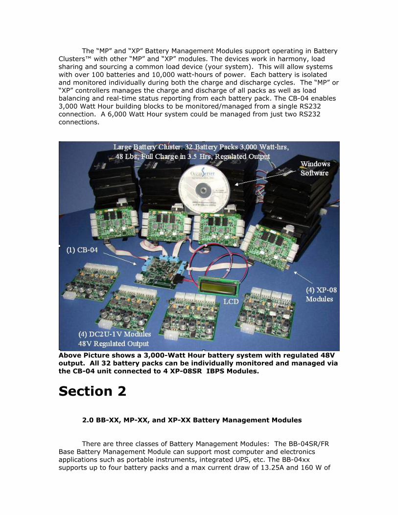
The “MP” and “XP” Battery Management Modules support operating in Battery Clusters™ with other “MP” and “XP” modules. The devices work in harmony, load sharing and sourcing a common load device (your system). This will allow systems with over 100 batteries and 10,000 watt-hours of power. Each battery is isolated and monitored individually during both the charge and discharge cycles. The “MP” or “XP” controllers manages the charge and discharge of all packs as well as load balancing and real-time status reporting from each battery pack. The CB-04 enables 3,000 Watt Hour building blocks to be monitored/managed from a single RS232 connection. A 6,000 Watt Hour system could be managed from just two RS232 connections.
Above Picture shows a 3,000-Watt Hour battery system with regulated 48V output. All 32 battery packs can be individually monitored and managed via the CB-04 unit connected to 4 XP-08SR IBPS Modules.
Section 2
2.0 BB-XX, MP-XX, and XP-XX Battery Management Modules
There are three classes of Battery Management Modules: The BB-04SR/FR
Base Battery Management Module can support most computer and electronics applications such as portable instruments, integrated UPS, etc. The BB-04xx supports up to four battery packs and a max current draw of 13.25A and 160 W of

power. This works out to 40W per battery when using OceanServer’s 14.4V BA95HC Smart batteries. The BB-04SR/FR can be paired with the DC-123SR module for regulated ATX output. The MP-04R/08R, MP-04SR/FR and MP-08SR/FR Battery Management Modules support up to four/eight battery packs on a single controller and support higher power levels. The MP-04R and MP-04SR/FR controllers provide up to 20A and 240W of power. The MP-08R, and MP-08SR/FR controllers provide up to 40A maximum, and 480W of power. This works out to 60W per battery when using OceanServer’s 14.4V BA95HC Smart batteries. The XP-04SR/FR, and XP-08SR/FR Battery Management Modules support up to four or eight battery packs and supports the highest level of output power. The XP-04SR/FR provide up to 26.5A and 320W of power. The XP-08SR/FR supports up to 53.25A and 640W of power. This works out to 80W per battery when using OceanServer’s 14.4V BA-95 Smart batteries.
Each MP or XP Battery Controller can have its own battery cluster of up to 4/8 batteries. By using the MP or XP Battery Controller, multiple groups of batteries can be clustered together in parallel to create one large Battery Cluster™ that is capable of outputting over 12,000 Watt-hours of power while still monitoring each individual battery pack. The Battery Controller modules manage Smart Li-ion battery packs. They manage the charge and discharge of all packs as well as load balancing and real time status reporting from each battery pack. The controllers include Level 3 Smart Battery Chargers (Smart Battery Charger Specification, V1.1) that will simultaneously charge all battery packs when an 18V DC charge voltage is provided to the DCIN connectors. The charge voltage will also source the power to the user device. The Battery Controllers can operate autonomously or can communicate to a host system via an RS232 port to report real time status. When connected to a host system, some advanced features of the controllers can be configured to meet the specific needs of your system, including shutdown parameters. Once configured, the host system is no longer needed and the controllers will run as configured. If left connected to a host system via the RS232 port, full ASCII status is also available. Two management programs can be used to monitor the operating IBPS modules. The OceanServer Minibats™ program, running on a Windows™ host system, will perform the management functions found on a Laptop computer. Minibats™ can take action when the system's battery capacity reaches user determined set points. The three actions are (1) warning - system power low; (2) run a program, or (3) shut down (or hibernate) the Windows™ computer. The OceanServer Fullbats™ program, running on a Windows™ host system, will perform the management functions found on a Laptop computer, plus detailed status of the complete IBPS system down to each battery pack. Additionally, Fullbats is a useful development tool when testing or evaluating system power consumption. The tool allows the user to monitor the operation of each controller and battery in larger configurations. Fullbats™ can support up to 16 controllers for a total of 128 batteries.
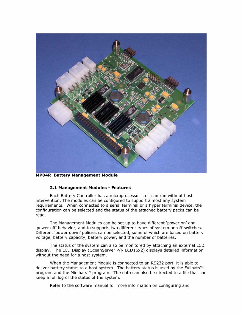
MP04R Battery Management Module
2.1 Management Modules - Features
Each Battery Controller has a microprocessor so it can run without host intervention. The modules can be configured to support almost any system requirements. When connected to a serial terminal or a hyper terminal device, the configuration can be selected and the status of the attached battery packs can be read.
The Management Modules can be set up to have different ‘power on’ and ‘power off’ behavior, and to supports two different types of system on-off switches. Different ‘power down’ policies can be selected, some of which are based on battery voltage, battery capacity, battery power, and the number of batteries.
The status of the system can also be monitored by attaching an external LCD display. The LCD Display (OceanServer P/N LCD16x2) displays detailed information without the need for a host system.
When the Management Module is connected to an RS232 port, it is able to deliver battery status to a host system. The battery status is used by the Fullbats™ program and the Minibats™ program. The data can also be directed to a file that can keep a full log of the status of the system.
Refer to the software manual for more information on configuring and
monitoring the Battery Controller modules. 2.2 Management Modules - Operation
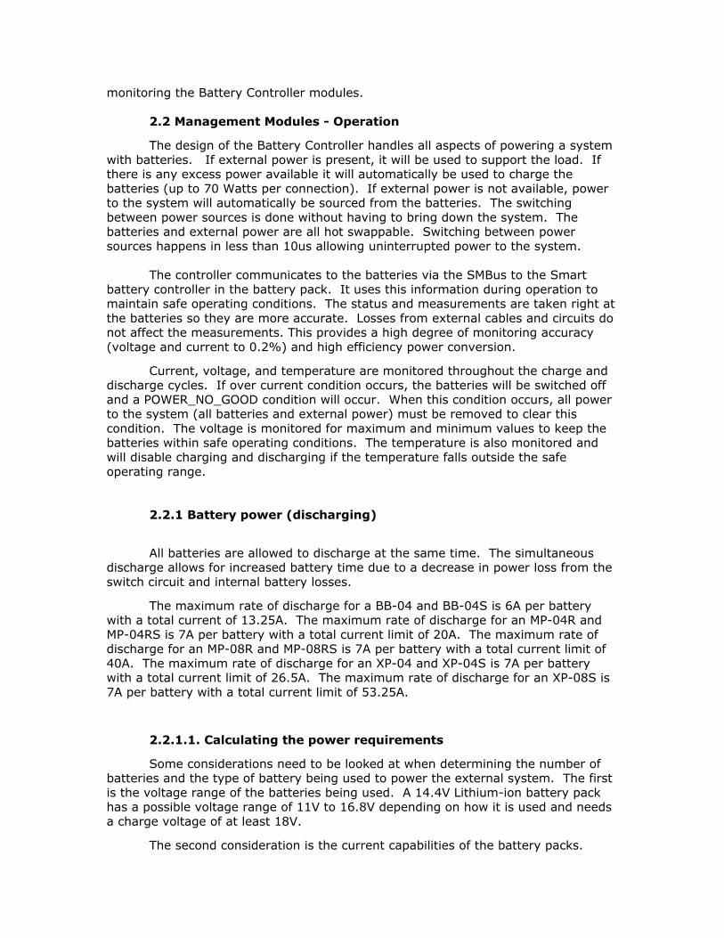
The design of the Battery Controller handles all aspects of powering a system with batteries. If external power is present, it will be used to support the load. If there is any excess power available it will automatically be used to charge the batteries (up to 70 Watts per connection). If external power is not available, power to the system will automatically be sourced from the batteries. The switching between power sources is done without having to bring down the system. The batteries and external power are all hot swappable. Switching between power sources happens in less than 10us allowing uninterrupted power to the system. The controller communicates to the batteries via the SMBus to the Smart battery controller in the battery pack. It uses this information during operation to maintain safe operating conditions. The status and measurements are taken right at the batteries so they are more accurate. Losses from external cables and circuits do not affect the measurements. This provides a high degree of monitoring accuracy (voltage and current to 0.2%) and high efficiency power conversion.
Current, voltage, and temperature are monitored throughout the charge and discharge cycles. If over current condition occurs, the batteries will be switched off and a POWER_NO_GOOD condition will occur. When this condition occurs, all power to the system (all batteries and external power) must be removed to clear this condition. The voltage is monitored for maximum and minimum values to keep the batteries within safe operating conditions. The temperature is also monitored and will disable charging and discharging if the temperature falls outside the safe operating range. 2.2.1 Battery power (discharging)
All batteries are allowed to discharge at the same time. The simultaneous discharge allows for increased battery time due to a decrease in power loss from the switch circuit and internal battery losses.
The maximum rate of discharge for a BB-04 and BB-04S is 6A per battery with a total current of 13.25A. The maximum rate of discharge for an MP-04R and MP-04RS is 7A per battery with a total current limit of 20A. The maximum rate of discharge for an MP-08R and MP-08RS is 7A per battery with a total current limit of 40A. The maximum rate of discharge for an XP-04 and XP-04S is 7A per battery with a total current limit of 26.5A. The maximum rate of discharge for an XP-08S is 7A per battery with a total current limit of 53.25A.
2.2.1.1. Calculating the power requirements
Some considerations need to be looked at when determining the number of batteries and the type of battery being used to power the external system. The first is the voltage range of the batteries being used. A 14.4V Lithium-ion battery pack has a possible voltage range of 11V to 16.8V depending on how it is used and needs a charge voltage of at least 18V.
The second consideration is the current capabilities of the battery packs.
When calculating the total power needed from the batteries to power the external system it is necessary to take into consideration the limitation on the current sharing capabilities of the batteries. It is necessary to de-rate the current rating of the batteries if more than one battery is needed to support the power requirements of the external system. When only one battery is necessary to satisfy the power requirements of the external system, then the rated current capacity of the battery can be used. For each additional battery pack that is installed, de-rate the current capacity by about 20% before calculating the output power.
It is necessary to determine the minimum number of battery packs needed to meet the power requirements of the external system. Once that is determined, based on using lowest battery voltage and minimum current sharing capabilities, it is necessary to shutdown the external system if the number of batteries becomes less than this number.
If the shutdown mechanism is disabled, the battery packs will shutdown at the fully discharged point in their cycles. This can cause problems if the system cannot be fully powered by the remaining batteries. As batteries reach this point they will stop supplying current to the system, this will force the remaining batteries to increase their output current to support the load. When a pair of batteries observes excess current between the pair the POWER_NO_GOOD FET fuse will activate. When the POWER_NO_GOOD FET fuse is activated, the batteries cannot be charged or discharged. This condition is latched and can only be cleared by removing all power from the controller.
See chapter on Configuring Complete Systems for more details.
2.2.2 Battery Charging / External Power
The IBPS acts much like an ordinary laptop charging system in that when it senses a valid DCIN voltage at the input connector (one connector for each pair of batteries) the IBPS simultaneously provides power to the system load and charges the batteries with the excess current.
The controller is an integrated Level 3 battery charger and automatically handles all aspects of battery charging. Throughout all charging the batteries are monitored for temperature to make sure it is safe to charge.
‘Wake-up’ charging happens on newly installed batteries that don't respond to read commands. If two batteries requiring a wake-up charge are installed on the same charging circuit, only one battery at a time will wake-up charge. Wake-up charging takes priority over a controlled charge to allow for both batteries to be control charged at the same time.
During a controlled charge, both batteries can be charged simultaneously to reduce the charge time for both batteries. The controller will request the voltage and current requirements of the batteries and charge accordingly. The voltage and current are monitored throughout the charge cycle and will terminate the charge cycle if the batteries become fully charged, AC power is removed, or it is unsafe to continue charging. Due to the current sharing, batteries will finish charging at roughly the same time.
The charge voltage depends on the battery packs being charged. In the case of the standard 14.4V Lithium-ion packs currently supplied by OceanServer, an 18V Regulated DC wall adapter is supplied. If simultaneous charging and system operation is desired, the power supply must be sized to supply the maximum power required to run the system and still have enough power left over to charge the
batteries.
If the system load is running concurrently with the charging load, enough current must be present to source the system load. The DC supply must be capable of safely operating in a current limited mode if it can’t fully source the load. If the supply cannot source the load, the voltage will reduce (fold) to current limit. The system will draw the maximum current and source the load first then charge the batteries with any remaining capacity.
The batteries are grouped in pairs for charging with one external power input supply connector for each pair. Up to 4A can be supplied to a battery pair when charging. If two batteries are installed and are at the same charge state, about 2A will be supplied to each battery. If only one battery is installed, it can take up to 4A. The maximum external voltage that can be supplied to an IBPS Management Module charging circuit is 24V.
The maximum current to the external system from an external power supply is 6 Amps per connection for the standard modules and 12A for the “SR” and “FR” variants. This must be taken into consideration when powering a system from an external supply.
The Battery Controllers support charging from weak sources such as Solar Panels or Fuel Cells. (See OceanServer Application Notes on Solar Charging and using with Fuel Cells).
During system charging from external power supply the output voltage of the controller equals the input voltage from the external power supply.
2.3 LEDs The IBPS controller module has 3 LED status indicators. The LED indicators are off by default to conserve power. If you want to enable the LEDs, change the firmware setting of the LCD to “OFF” (see the IBPS Software Manual for more details on configuring the LCD). D36 is a green LED. It can be used to monitor the percent of charge in the battery system when the system is discharging. The LED will blink and the ratio of the time on vs. the time off will indicate the percent of charge left on the batteries. Always on will indicate fully charged. D37 is an amber LED. It can be used to monitor the percent of charge in the battery system when the system is charging. The LED will blink and the ratio of the time on vs. the time off will indicate the percent of charge on the batteries. Always on will indicate fully charged. D38 is an amber LED. It can be used to monitor the PS_ON# signal from the ATX power connector on the DC-023R. Important Note: Not all OceanServer boards have LEDs. The boards which do have LEDs include the BB-04, MP-04R, MP-08R, BBDC-02. These boards will have an “R” at the end of the part number if they are RoHS compliant.

2.4 Configuring the Battery Management Modules
All that is needed to run an IBPS Battery Controller is a connection to a battery pack and a connection to your system. If you want to charge your system, then an external power source will need to be connected. There is one connection to an external power source for each pair of batteries. Advanced configuration options can be changed through an RS232 port connection. Monitoring the status of the battery packs can be done in two ways. The first is by connecting to an RS232 port and using the Minibats™ or Fullbats™ program in a Window (TM) based system. It is also possible for the IBPS to output battery status and information to the serial port to be captured by user their custom software applications. The data stream complies with the RS232 NEMA format. The battery status can also be viewed via an LCD display. The display can be set up to show the percent of charge or discharge, remaining capacity or time to full charge, and the amount of power being consumed or supplied by the batteries.
2.4.1 Connectors (Base Model MP-O4R)

The MP-04R is a single board in PC104 form factor. The connectors extend beyond PC104 size. The MP-08R (below) is a two-board stack. All of the boards have mechanical drawings and 3D Models available on the OceanServer Download page. Connectors for “S” version modules (BB-04SR, MP-xxSR, XP-xxSR)
The BB-04SR, MP-04SR, and XP-04SR are a single board 3.59”x 2.92”. The MP-08SR and XP-08SR (below) are both a two-board stack similar to the MP-08R. All of the boards have mechanical drawings and 3D Models available on the OceanServer Download page.

XP-08SR MP-08R The “SR” version board can be requested in PC104 size and RoHS compliant. Part Numbers for “S” version boards: Non RoHS Ordering Part Numbers: BB-04S, MP-04S, MP-08S, XP-04S, XP-08S Module size is 2.917" x 3.583" RoHS Compliant Ordering Part Numbers (R at end of part number is for RoHS): BB-04SR, MP-04SR, MP-08SR, XP-04SR, XP-08SR Small Size: 2.917" x 3.583" BB-04FR, MP-04RFR, MP-08RFR, XP-04FR, XP-08FR Full Size (PC104) Size: 3.6" x 3.8" All part numbers are functionally the same. The part numbers ending in “FR” are built with extended etch which includes the PC104 mounting holes (see picture on next page).
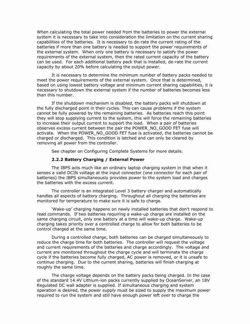
Base Battery Management Module
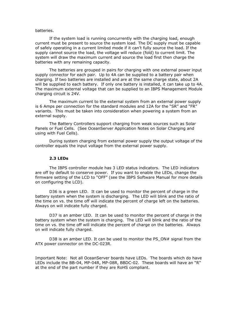
2.4.1.1 Battery Connectors (J12, J17, J21, and J22) Up to 4 Smart Battery Packs can be connected directly to the Base Battery Management Module. The module will autonomously handle and monitor all aspects of the battery behavior, switching them into the circuit to supply power to the system and charging when needed. Battery 1 is connected to J12. Battery 2 is connected to J21. Battery 3 is connected to J17. Battery 4 is connected to J22.
Pin 1
Pin 3
Pin 4
Pin 6
J12, J17, J21, and J22 (looking into connector)
SDA
SCLGNDGND
V+ TH
Extended etch of Full Size “FR” modules
PC104 Mounting Holes

2.4.1.2 External Power Connectors (J5 and J7) AC adapters or power supplies can be connected to J5 and J7. An external power source is not needed, but if attached, the power can be used to simultaneously run the system and charge the batteries (if needed). One power supply can be connected to both J5 and J7 if it can supply enough power to meet the systems needs. The AC adapter or power supply should be capable of producing between 18 to 24 volts. For the standard modules, 6 Amps of power can be delivered to the system through J5 and 6 Amps can be delivered to the system through J7. This allows for a total of 12 Amps that can be supplied to the system from external power. For the “S” and “F” variant modules, 12 Amps of power can be delivered to the system through J5 and 12 Amps can be delivered to the system through J7. This allows for a total of 24 Amps that can be supplied to the system from external power. Up to 70W power can be sourced from each connector for charging. Power connected to J7 will be used to charge batteries 1 and 2. Power connected to J5 will be used to charge batteries 3 and 4.
2.4.1.3 Control and Status Connector (J1) J1 is used for external status and control of the Base Module. The connector supports an external power switch, which will generate an external off/on signal that can be used by an external system. The connector also supports two external LED signals and an LCD display. 2.4.1.3.1 External switch A 2 pin header connector attached to a switch (cable 19-00027-00) and connected to pins 2 and 4 can be used to turn the DC-023R Module on and off and to generate an external on/off signal (see section 2.4.1.3.2).
Two switch types are supported, a toggle switch and a momentary pushbutton switch. When configured as a toggle switch, an open circuit will turn the device off; a closed circuit will turn it on. When configured as a momentary pushbutton switch, the controller assumes that a momentary switch is attached. By using a normally open switch, closing the switch when the DC-023R/DC-123SR module (or your system) is off will turn it on. Closing the switch when the DC-023R module (or your system) is on will turn it off. To avoid unintentionally turning off a system, the momentary switch can be configured to delay before turning off. When in this mode, the switch will need to be held closed for about 3 seconds before turning the DC-023R/DC-123SR module (or your system) off. When off, momentarily pushing the switch will turn the system on.
The momentary switch also allows you to connect the controller to a PC. The
Pin 1 Pin 2
J5 and J7 (looking into connector)
DC_IN GND

controller will monitor the PS_ON# signal from a PC motherboard. The PS_ON# signal is routed through a DC-023R/DC-123SR DCDC module. When using the IBPS to power a PC (using the ATX power connector on a motherboard) you must make sure that the BIOS is set to “AC Loss Auto restart” [ON] or the motherboard will expect that its power button is pushed. This is required since the IBPS DC-023R/DC-123SR does not supply +5VSB when power is turned off, to conserve battery power. Note that the switch does not disconnect battery power to the DC-023R/DC-123SR (or your external system). It only generates an “ON/OFF#” signal. Battery power will always be available unless the batteries are fully discharged. See the IBPS Software Manual for more details on configuring the switch type. 2.4.1.3.2 External power signal A 2 pin header connector attached to pins 6 and 8 will provide a TTL output that can be used for an external ON/OFF# signal (pin 6 is the TTL output and pin 8 is ground). The output is configured to be high when the system is turned on and will go low when the external system needs to be turned off. 2.4.1.3.2B Special considerations when connecting to a PC
(Enabling Auto Restart) When using our power controller with ATX motherboards you need to configure the BIOS to auto restart on AC Loss. There are two ways you can do this: 1) You can hook up your power standard supply like you normally do and go into the BIOS and change the setting. Then hook up our module and things should work. 2) You can hook up our module, and turn it on. Then temporarily short out the pushbutton pins on the motherboard connector (see your motherboard user manual). This should turn on the system. Then go into the BIOS and change the setting. From that point on you can turn it on with the pushbutton switch connected to the Battery Controller module. Motherboard BIOS: Power Management Setup AC Loss Auto restart [on] ON/OFF PC switch: Connect the 2 pin ON/OFF system momentary switch to connector J1 on the Battery Controller module, pins 2-4 (top row, upper left corner). When you hit the on/off switch we will turn on the power and the motherboard will boot. Note: This is done as Standby mode will draw too much current and drain the batteries. 2.4.1.3.3 Discharge status led

A 2 pin header connected to pins 1 and 2 can be used to control an external LED to monitor the percent of charge in the battery system when the system is discharging. The LED will blink about once a second and the ratio of the time on vs. the time off will indicate the percent of charge left on the batteries. Always on will indicate fully charged. Important Note: Not all OceanServer boards support LEDs. 2.4.1.3.4 Charge status led A 2 pin header connected to pins 7 and 8 can be used to control an external LED to monitor the percent of charge in the battery system when the system is charging. The LED will blink about once a second and the ratio of the time on vs. the time off will indicate the percent of charge on the batteries. Always on will indicate fully charged. Important Note: Not all OceanServer boards support LEDs. 2.4.1.3.5 External LCD display An external LCD display (OceanServer P/N LCD16X2 or LCD16x2BL for back-lighted version) can be attached to the controller on pins 3, 5, and 8 (cable 19-00034-00). This will allow for more detailed information to be displayed without the need of a host system. The LCD display contains two lines of information. One line is used for a bar graph displaying the amount of charge left in the battery system. The bar graph also indicates if the battery is charging or discharging. The second line of the LCD display can show the power consumption and the current entering or leaving the battery subsystem. The second line of the display can also show the time to full charge when charging the batteries or the time to full discharge the batteries when the batteries are supplying power to the system. The second line of the display is configurable and can be set up to show all or none of the data mentioned above. See the IBPS Software Manual for more information. The LCD display supports backlighting. To conserve battery power, backlighting should not be used if the system will be put to sleep. The LCD display will shut off when the system goes to sleep if power for the display is sourced only from J1 pin 3.
J1 Pin 1 – Green LED 2 – Ground 3 – LCD data 4 – External On/Off switch (weak pull-up to 5V input) 5 – 5V (20mA max.) 6 - Shutdown signal (TTL), turn off DC-DC or Load 7 – Yellow LED 8 - Ground
1 3
4
5
6
7
82

2.4.1.4 RS232 Port Connector (J8) The Battery Controller can be connected to a PC or other system through an RS232 serial port when connected to J8 through converter cable (19-00010-00). The converter cable connects to J8 and has a DB9 style connector to connect to a standard serial cable (19-00011-00). Connecting the BB-04 or MP-04R to a host system allows the user to monitor the battery/power system and to set up and configure advanced firmware features.
2.4.1.5 Test Connector (J9) J9 is used during manufacture and test. 2.4.1.6 Expansion Connecter (J10) J10 is used for attaching the MP-08R Expansion Module or DC-023R Converter Module. J10 on the “SR/FR” modules is used to connect to an expansion module or DC-123S module through a ribbon cable. 2.4.1.7 System Power Connector (J13) Raw battery power or power from the external power source is connected through the IBPS to your system through J13 (cable 19-00004-24). The module will monitor all power inputs and connect the appropriate power source to your system. The controller will automatically switch the power being supplied to the system from the batteries to the external power when an external power source is connected. Any remaining power capacity from the external power supply will be used to charge the batteries (if necessary). The power switching happens fast enough (<10us) so the system experiences no interruption in power.
10
9 7
8
5
6
3
4
1
2
J8 Pin 1 – tied to pins 2 and 7 2 – tied to pins 1 and 7 3 – TX_OUT 4 – tied to pin 6 5 – RX_IN 6 – tied to pin 4 7 – tied to pins 1 and 2 8 – no connect 9 – Ground 10 - +5V

Section 3
3.0 Expansion Battery Management Module
The Expansion Module supports up to 4 additional battery packs, for a total of 8 batteries and comes as part of an MP-08R, MP-08SR/FR, or XP-08SR/FR. It provides the off the shelf scale-ability when increased power is required. Note: Power connections to the expansion module will not supply power to the microcontroller. Battery or external power must always be present at the base module of the MP-08R or the processor will not operate.
MP-08R Battery Management Module
Pin 1
Pin 4
Pin 5
Pin 8
J13 (looking into connector)
GND
SYS_PWR GNDGND
SYS_PWR SYS_PWR
SYS_PWR GND
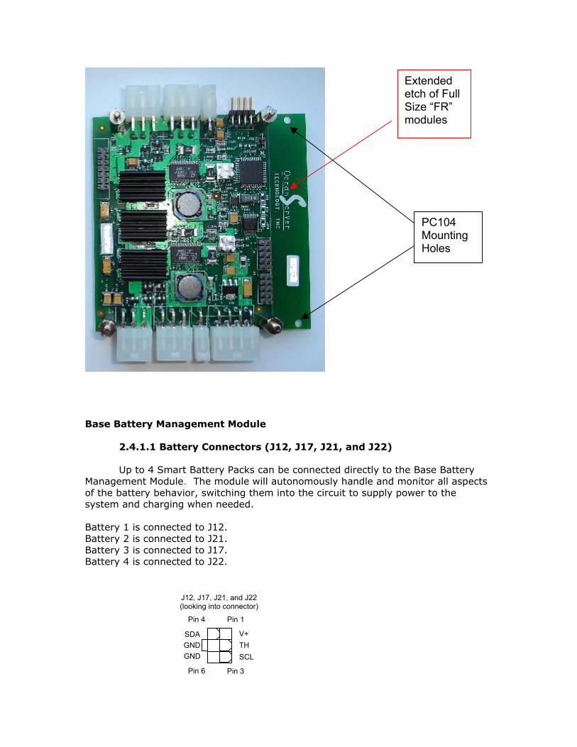
3.1 Configuring The connections to the “-08R” or “-08SR/FR” Expansion Modules have the same properties as the corresponding Base modules. The Expansion modules allow for up to 4 more batteries for a total of 8 per controller.
3.1.1 Connectors
MP-08R Expansion Battery Management Module 3.1.1.1 Expansion Battery Connectors Up to 4 Smart Battery Packs can be connected directly to the Expansion Module. The battery connectors have the same characteristics as the ones on the Base module. The “SR/FR” module connectors are numbered the same as on the Base module. On the non ”SR/FR” version, the connectors are J18, J19, J23, and J24. Battery 5 is connected to J19 (J12 for the “SR/FR” version). Battery 6 is connected to J23 (J21 for the “SR/FR” version). Battery 7 is connected to J18 (J17 for the “SR/FR” version). Battery 8 is connected to J24 (J22 for the “SR/FR” version).
J19
J23
J2
J6
J18
J24
J16
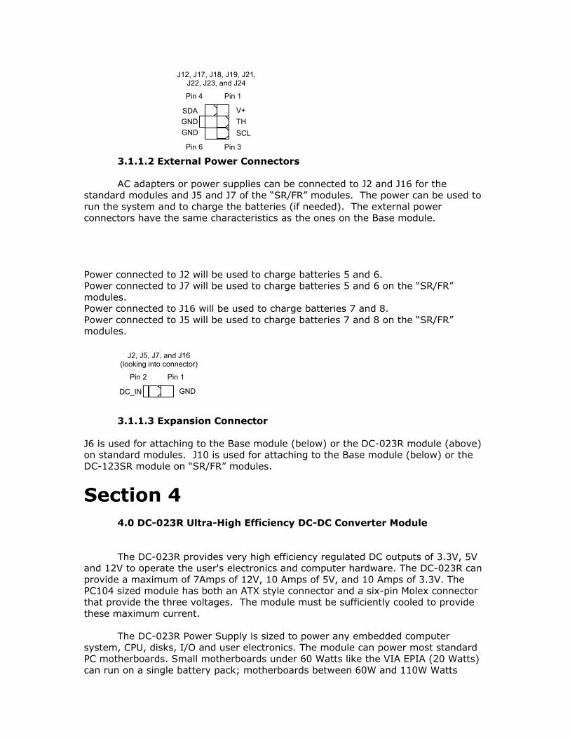
3.1.1.2 External Power Connectors AC adapters or power supplies can be connected to J2 and J16 for the standard modules and J5 and J7 of the “SR/FR” modules. The power can be used to run the system and to charge the batteries (if needed). The external power connectors have the same characteristics as the ones on the Base module. Power connected to J2 will be used to charge batteries 5 and 6. Power connected to J7 will be used to charge batteries 5 and 6 on the “SR/FR” modules. Power connected to J16 will be used to charge batteries 7 and 8. Power connected to J5 will be used to charge batteries 7 and 8 on the “SR/FR” modules.
3.1.1.3 Expansion Connector J6 is used for attaching to the Base module (below) or the DC-023R module (above) on standard modules. J10 is used for attaching to the Base module (below) or the DC-123SR module on “SR/FR” modules.
Section 4
4.0 DC-023R Ultra-High Efficiency DC-DC Converter Module
The DC-023R provides very high efficiency regulated DC outputs of 3.3V, 5V
and 12V to operate the user's electronics and computer hardware. The DC-023R can provide a maximum of 7Amps of 12V, 10 Amps of 5V, and 10 Amps of 3.3V. The PC104 sized module has both an ATX style connector and a six-pin Molex connector that provide the three voltages. The module must be sufficiently cooled to provide these maximum current. The DC-023R Power Supply is sized to power any embedded computer system, CPU, disks, I/O and user electronics. The module can power most standard PC motherboards. Small motherboards under 60 Watts like the VIA EPIA (20 Watts) can run on a single battery pack; motherboards between 60W and 110W Watts
Pin 1
Pin 3
Pin 4
Pin 6
J12, J17, J18, J19, J21, J22, J23, and J24
SDA
SCLGNDGND
V+ TH
Pin 1 Pin 2
J2, J5, J7, and J16 (looking into connector)
DC_IN GND

require two BA-95 battery packs to provide sufficient power to operate the load. If you need additional power at a given voltage you can connect two DC-023R modules and double the current from any voltage rail. The ATX connector provides the POWERON and POWEROK signals for ATX motherboards. The DC-023R does not provide 5VSB. The 5VSB is connected to +5V. This requires the user to setup the motherboards to TURN ON after POWER FAIL. The standard DC-023R does not provide –12V. The DC-023R does have the option to provide –12V to the ATX power connector. Contact OceanServer for information regarding optional support of -12V. There is no support for –5V on the ATX power connector.
DC-023R Ultra-High Efficiency DC-DC Converter Module 4.1 Configuring the DC-023R
To use the integrated DC-023R in a system, a ‘four-series’ Lithium-ion pack is required. An input above 12.4V minimum is required. A DC-023R with adequate cooling can deliver 167-Watts with sufficient batteries connected to the system. If the IBPS is used in a still air environment, or in a smaller space, the output power

should be de-rated. Note: at the maximum current you need to pay attention to the IR drop across the cable sourcing your load. When using ATX power connectors on motherboard designs you must make sure the BIOS is set to “AC Loss Auto restart”[ON] or the motherboard will expect that its power button is pushed. This is required, as we do not supply the motherboard with stand-by power when the power is turned off. This is to conserve the battery power.
For extra +12V CPU power, additional cables can be attached to J25 (cables 19-00030-03 and 19-00028-12). For extra disk power an additional cable can be attached to J25 (cable 19-00030-03). For extra +12V CPU power and disk power, the adapter cable (19-00030-03) can be connected to a “Y” disk cable (19-00016-00). There will then be one cable connection for disks and the other for the additional +12V CPU power (using cable 19-00028-12). 4.1.1 DC-023R Connectors DC-023R Ultra-High Efficiency DC-DC Converter Module 4.1.1.1 ATX Style Power Connector (J20) J20 is an ATX style power connector. This can be hooked directly up to a PC
J20
J25
J1

motherboard or system that supports and ATX style connection (cable 19-00014-00). +5VSB is supplied connected to +5V, so there is no stand by power when the power is turned off. Power is supplied to the pin when the regular +5V is turned on. -12V is not supported on the standard DC-023R but can be added as an option.
4.1.1.2 Power Connector (J25)
J25 is a 6-pin connector that provides +12V, +5V, and +3.3V outputs and can be connected to your system (cable 19-00031-16).
4.1.1.3 Stacking Connector
J11 is used for attaching to the BB-04, MP-04R or MP-08R Module. 5.0 DC-123SR Ultra-High Efficiency DC-DC Converter Module
The DC-123SR provides very high efficiency (144 Watt Max) regulated DC
outputs of 3.3V, 5V and 12V to operate the user's electronics and computer hardware. The DC-123SR can provide a MAXIMUM of 12Amps of 12V, 10 Amps of 5V, and 10 Amps of 3.3V. Unlike the DC023 –12V is a standard voltage. The 2.91”X 3.58” sized module has both an ATX style connector and a four-pin Molex connector
Pin 11 Pin 1
Pin 10 Pin 20
J20 (looking into connector)
+3.3V +3.3V
+3.3V
GND GND
GND
GND
(optional support) -12V
+5V
+5V
PWR_OK +5V (+5VSB) +12V
PS_ONGNDGNDGND
(not supported) –5V+5V+5V
Pin 1
Pin 3
Pin 4
Pin 6
J25 (looking into connector)
GND
+12V GNDGND
+3.3V +5V
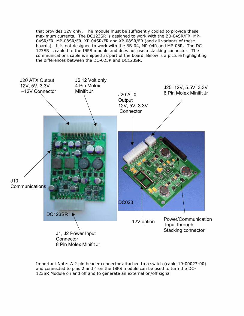
that provides 12V only. The module must be sufficiently cooled to provide these maximum currents. The DC123SR is designed to work with the BB-04SR/FR, MP-04SR/FR, MP-08SR/FR, XP-04SR/FR and XP-08SR/FR (and all variants of these boards). It is not designed to work with the BB-04, MP-04R and MP-08R. The DC-123SR is cabled to the IBPS module and does not use a stacking connector. The communications cable is shipped as part of the board. Below is a picture highlighting the differences between the DC-023R and DC123SR.
Important Note: A 2 pin header connector attached to a switch (cable 19-00027-00) and connected to pins 2 and 4 on the IBPS module can be used to turn the DC-123SR Module on and off and to generate an external on/off signal
J20 ATX Output 12V, 5V, 3.3V –12V Connector
J6 12 Volt only 4 Pin Molex Minifit Jr
J1, J2 Power Input Connector 8 Pin Molex Minifit Jr
J10 Communications
DC123SR -12V option Power/Communication
Input through Stacking connector
J25 12V, 5.5V, 3.3V6 Pin Molex Minifit Jr J20 ATX
Output 12V, 5V, 3.3V Connector
DC023

DC123SR Connector Pinouts:
Section 5
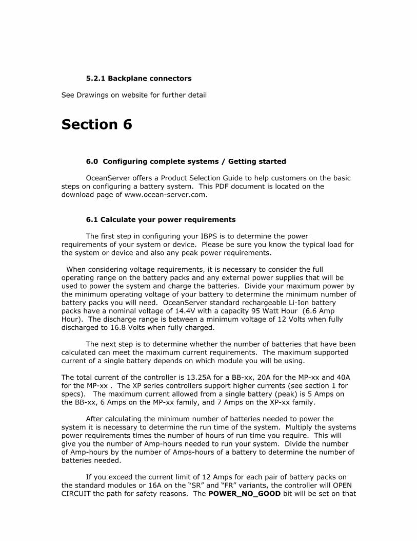
5.0 Batteries The battery subsystem is very compact due the high energy density of the Li-ion cells. Each battery pack has a complete safety circuit, fuel gauge and communication port that is used by the system to collect detailed information about each pack’s operation. Each battery pack is isolated and monitored during the charge and discharge cycles. The charger won’t apply voltages unless it can read the packs internal voltage, current data and status flags. If there is a problem, the IBPS will stop charging or discharging the pack. In addition each pack has multiple levels of protection. They will not allow a defective charger to put current into the pack or the discharge cycle to remove current from the pack if there is a safety condition being violated. Safety limits involve, Min/Max Voltages, Max Current, and Min/Max Temperatures. The following table summarizes the differences between the batteries.
Battery Style Cable Length*
Rough Dimensions**
BA-95*** N/A 6.25” x 4.3” BA-95HC N/A 6.25” x 4.3” BA-95-FL*** ~2” 6.25” x 4.3” BA-95HC-FL ~10” 6.25” x 4.3” BA-95HCL-FL ~10” 11.00” x 2.4”
*Cable length can be increased by using extension cables. (6” extension cable p/n 19-00035-06) ** Length dimension does not include housing for battery contacts (~.35”). See specification for exact dimensions.
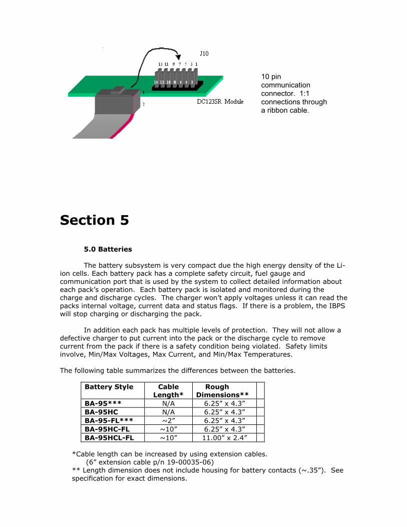
10 pin communication connector. 1:1 connections through a ribbon cable.

*** Obsolete not recommended for new designs. Note: The new HC batteries have a more efficient MOSFET circuit and presents lower losses on discharge. In our system the MP-xx and BB-04 current limits must be followed. See the specifications at the end of this document.
5.1 Battery Calibration Each smart battery pack in the system maintains it’s own coulomb counter fuel gauge. When the battery pack sees an uninterrupted discharge cycle, followed by a charge cycle, then another discharge-charge cycle, it will recalibrate the fuel gauges. The battery capacity is not affected by this calibration; only the accuracy of the fuel gauges is affected. If after the first discharge/charge cycle the max error of all batteries is 2%, then the second discharge/charge cycle isn't necessary. The Battery Controllers starting with V2.0 of the firmware have an enhanced fuel gauge that uses system level data to help improve the accuracy of the fuel gauges.
5.2 Backplanes OceanServer supports a single and dual backplane that can be used for hot swapping battery packs.
Single and Dual Battery backplanes
Another backplane option is the below single Backplane cable with connector.
5.2.1 Backplane connectors See Drawings on website for further detail
Section 6
6.0 Configuring complete systems / Getting started OceanServer offers a Product Selection Guide to help customers on the basic steps on configuring a battery system. This PDF document is located on the download page of www.ocean-server.com.
6.1 Calculate your power requirements The first step in configuring your IBPS is to determine the power requirements of your system or device. Please be sure you know the typical load for the system or device and also any peak power requirements. When considering voltage requirements, it is necessary to consider the full operating range on the battery packs and any external power supplies that will be used to power the system and charge the batteries. Divide your maximum power by the minimum operating voltage of your battery to determine the minimum number of battery packs you will need. OceanServer standard rechargeable Li-Ion battery packs have a nominal voltage of 14.4V with a capacity 95 Watt Hour (6.6 Amp Hour). The discharge range is between a minimum voltage of 12 Volts when fully discharged to 16.8 Volts when fully charged. The next step is to determine whether the number of batteries that have been calculated can meet the maximum current requirements. The maximum supported current of a single battery depends on which module you will be using. The total current of the controller is 13.25A for a BB-xx, 20A for the MP-xx and 40A for the MP-xx . The XP series controllers support higher currents (see section 1 for specs). The maximum current allowed from a single battery (peak) is 5 Amps on the BB-xx, 6 Amps on the MP-xx family, and 7 Amps on the XP-xx family. After calculating the minimum number of batteries needed to power the system it is necessary to determine the run time of the system. Multiply the systems power requirements times the number of hours of run time you require. This will give you the number of Amp-hours needed to run your system. Divide the number of Amp-hours by the number of Amps-hours of a battery to determine the number of batteries needed. If you exceed the current limit of 12 Amps for each pair of battery packs on the standard modules or 16A on the “SR” and “FR” variants, the controller will OPEN CIRCUIT the path for safety reasons. The POWER_NO_GOOD bit will be set on that

channel. To reset this condition all batteries and charge voltages must be removed from the system. The design of the system should avoid this condition under normal operation. The lower power limits per channel are to allow for current sharing and adding of the batteries while maintaining a safety margin. Additional things to consider when determining power requirements - Efficiency of any external DCDC converters - IR drops of cables in higher current applications - N+1 operation - voltage range of battery and external power supply 6.2 Providing external power After determining the number of batteries needed, it is necessary to determine the amount of power you need to charge all of the batteries and simultaneously power the system (if required). The amount of power required depends on how fast you want the batteries to recharge. The controller can supply up to 4A of current at 16.8V for each pair of batteries (almost 70W). The charger has a very efficient DC-DC converter that produces the variable charge voltage from the DCIN supply. This is typically 18V in our standard systems. The charger supports charge voltages up to 24V. The power from an external supply can be used for two purposes. One is to charge the batteries and the other to supply power to your system. If configured properly, both objectives can be met simultaneously. The IBPS will only charge the batteries if there is sufficient current available. The batteries are arranged in pairs (1 and 2, 3 and 4, and on the MP-08R, 5 and 6, 7 and 8). Each pair has its own power supply input for charging and supplying power to the system Each battery control pair will supply a maximum of 4 Amps of charge current at 16.8V to the batteries. They will charge simultaneously so they will charge in approximately 3.5Hours for the pair (using 95Whr, 14.4V packs). If you attach a single battery to the pair of connections leaving one unconnected, the packs will charge in under 2 hours. This wastes slots but can be used to create a system with fast charging. This will charge at the 4Amp maximum of the BA-95HC packs. Even with a single battery pack it will still take 70 watts of power. There are two connections for an external supply on the the MP-04R, and four connections on an MP-08R. Each connection is able to source up to 6 Amps of current to the system load. If the system load requires more than 6A of power per connection you could damage the IBPS. Important Note: New IBPS boards ending “SR” and “FR” can now support up to 12 Amps per connection from the power supply to the system. In addition to the current being supplied to the system, excess available current will be used to charge the batteries. The excess available charge current is determined by individually monitoring the current being supplied by each external connection. The controller will divert all excess current to charge the batteries up until the total current (current to the system plus the current to charge the batteries) equals 6.6 Amps (or until the maximum battery charge current is reached). The IBPS boards ending “SR” and “FR” can now support up to 16.6A Amps.

Block diagram of the power path from a single external power supply connection to the system load. If you use an external power supply for charging that cannot supply the required power it should FOLDBACK it’s voltage in an over current situation. If the load and charge circuit try to draw more than 6.6Amps per pair For the standard modules and 16.6A for the “S” and “F” variants, the controller will limit the charging current to keep the DCIN current under this point. Remember the system will try to supply power to your load at the higher DCIN voltage when you are charging the system. When the charge voltage folds back under the battery voltage the current will be sourced from the batteries. Note, even "weak" power sources such as small solar panels can be used to power the system and charge the batteries (see OceanServer Application Note AN101 on Solar Charging). The solar panels should have an open circuit voltage of above 20V and the charger will take as much current as is produced from the solar panels. Using a 10Watt output panel it is possible to charge all eight battery packs on an MP-08R with very good efficiency at capturing the energy delivered. The DC-DC that creates the charge voltage is ultra efficient, about 95%, harvesting most of the energy to the battery packs.
Some examples of weak charging sources such as fuel cells, solar cells, and other small power generators in the range of 17-24 VDC will be shown on the OceanServer website at http://www.ocean-server.com/

6.3 Advanced Features
All that is needed for power your system is the BB or MP controller, battery packs and an external power source for charging the batteries. The system operates autonomously and will always source battery voltage to your load if the packs are in a safe range to operate. The controller provides an OUTPUT signal that will signal the end of allowable discharge and should be used to shutdown your load. If you’re using one of the OceanServer DC-DC converters it will have a two pin connection to this signal to shut it down when the either the power is switched off or the system has reached the end of discharge shutdown point. The controller has many methods that you can configure to signal the end of discharge based on the policy that best suits your needs. Typically you would set up the controller to shutdown when 1-3 packs have reached fully discharged state (FD bit set). This is the point when the battery pack will open its FET and stop sourcing current. The battery pack still has enough energy to go a few weeks before you must recharge the battery pack. Example: A system has 4 battery packs and the maximum power draw, 60Watts by the load can be supplied by one battery pack. System shutdown could be set when 2 packs are FULLY_DISCHARGED, leaving 2 packs still sourcing current. At this point the controller will signal the external DC-DC to shutdown. In addition, the controller can be set to sleep when it shutdowns the power, either by switch or by reaching the end of discharge. The controller takes about 20 ma at battery voltage to operate if it is not asleep so it will slowly discharge the packs if not put to sleep. An external switch is needed to wake the controller back up. Note, that even though the controller is still asleep, battery power (if available) will still be connected to the load. The controller parameters can be set using a TEXT terminal such as HyperTerm in Windows™ and talk to the controller, 19200 Baud, No parity, No handshake. The command “S” setup, “N” NVRAM will bring you into the setup menu. See the software manual for details. --- Example configuration log from HYPERTERM, COM1: 19200Baud, Nop, Nohs – IBPS BB-04 V1.66 OceanServer Technology, Inc (c) 2005 151 Martine Street Fall River, MA 02723 www.ocean-server.com S - Setup Controller B - Battery Status X - Host HEX H - Help ->S ..Setup Controller . N - Set NVRAM Data . R - Reset NVRAM to Default values . E - Dump EERAM ->N Setup NVRAM Parameters.. This controllers ID (1) :
Startup Command character ( ) : PowerFlag, 1=TOGGLE-SWITCH, 2=MOMENTARY (2) : LCDon, 1=on, [1,0-1], new value: Cycle length, [14,2-50], new value: Disp 1, [1,1-50], new value: Disp 2, [5,1-50], new value: Clear, [9,1-50], new value: PIC Sleep,1=yes, [1,0-1], new value: Checksum on host data, 1=yes, [1,0-1], new value: Hold button down for off?,1=yes, [1,0-1], new value: Message delay in 0.4 sec , [4,4-40], new value: Controller Power Down Policy... Shutdown when charge pcnt < x, 1=yes, [0,0-1], new value: Min voltage for shutdown(SD), 1=yes, [0,0-1], new value: Min packcount SD, 1=yes, [0,0-1], new value: Fully Disch # for SD, 1=yes, [1,0-1], new value:1-1- # packs FD to shutdown, [2,1-7], new value:2-2- Max battery current SD, 1=yes, [1,0-1], new value:1-1- Max battery current, 0.1 amp, [60,20-60], new value:60-60- Total current SD, 1=yes, [1,0-1], new value:1-1- maximum current, amps, [32,6-32], new value:16-16- S - Setup Controller B - Battery Status X - Host HEX H - Help -> ------------------ End of HyperTerm Log ----------------------- 6.3.1 Advanced switch features If you want to be able to turn the your system off and on, and to put the microprocessor to sleep, you can connect an external power switch.
The IBPS Firmware can be set up to have different behavior for turning the system on and off. There are two switch options available, a toggle switch and a momentary push button (with two modes of operation). The switch is connected to J1 pin 2 and J1 in 4. When the toggle switch is closed, the system will turn on. When the toggle switch is open, it will shut off. The momentary push button switch has two modes of operation. The first will just turn the system on when the button is pushed and turn off the system the next time it is pushed. The third option (similar to most PCs) requires that the switch be held closed for several seconds before the power will go off. Refer to the Software Manual for configuring the switch.
It is also possible to turn the system off and on using an external TTL signal connected to J1 pin 4. A logic high will turn the system off and a logic low will turn the system on. Since the signal has a weak pull-up to 5V, it is also possible to use
an open drain or collector to control the switch input.
6.3.2 Advanced power control
The IBPS also provides an external signal on J1 pin 6 that can be used to tell external systems to power up or power down. This signal can be controlled via the switch input on J1 pin 2 or by the microprocessor based on shutdown policies that can be configured by the user. This is a TTL signal. A low on this signal will indicate power down. A high will indicate power up. A number of different shutdown policies can be configured in the microprocessor. These policies tell the external system to shutdown based on user-defined parameters. The parameters are charge percentage, minimum voltage, minimum number of battery packs, number of batteries fully discharged, maximum battery current, and maximum total current. Refer to the software manual for more details.
6.3.3 Advanced monitoring features Connecting a Base Battery Management Module to a host system will allow for advanced monitoring of the status of all battery packs in the system. Minibats™ can be used for basic information about one controller connected to a Windows™ system. It functions in a similar manner to a laptop power manager and supports a single controller (1-8 battery packs) maximum. It allows you to shutdown.
Fullbats™ supports multiple Base Modules and can give detailed information about the entire power subsystem-system, including a log of the batteries and system status. The controller can also be set up to stream battery status over a serial port connection that can be read by a user program.

6.3.4 Advanced display feature - LCD Display Detailed information about the status of the batteries without connecting to a host system can be viewed by connecting an external LCD display (OceanServer P/N LCD16x2 or LCD16x2BL for back-lighted version).
LCD Display The LCD display displays the fuel gauge (Bar graph and percent of relative capacity) as well as two different text fields. The first text display says if the system is charging or discharging and the approximate time to FULL or EMPTY. The second display shows the power consumption in Total Watts and Amps. This is the power flowing from the battery packs, where negative is a discharge current and positive is a charge current. It’s worth noting that all data displayed is from the battery terminal point of view. If you have a load consuming 100 Watts and you have a charge voltage applied that can supply 300 Watts you may only see a charge of 200 Watts. Since the current is flowing from the external power supply to the load directly without going through the battery packs, you don’t see this current. 6.4 Connecting to a PC motherboard... Attaching a DC-023R to a BB-04, MP-04R, or an MP-08R (or DC123SR in the case of the BB-04SR/FR, MP-04SR/FR, MP-08SR/FR, XP-04SR/FR or XP-08SR/FR) , creates a battery powered power supply. The power supply can be used as a UPS or can be used to make the system portable. To connect to a PC motherboard: 1) Connect your batteries 2) Connect an external power supply (if desired) 3) Connect an external momentary switch to J1 pin 2 and pin 4 (cable 19-00027-00). 4) Connect the DC-023R to the PC motherboard through J20 (cable 19-00017-00) 5) Connect any additional power needed for disks or +12V for CPU power through J25. The following cables are available to make any additional connections: -For extra disk power, use 19-00030-03 -For extra +12V CPU power, use cables 19-00030-03 and 19-00028-12)
-For extra +12V CPU power and extra disk power, use cables 19-00016-00, 19-00030-03, and 19-00028-12.
6) Now adjust the BIOS setting so “AC Loss Auto restart” [ON]
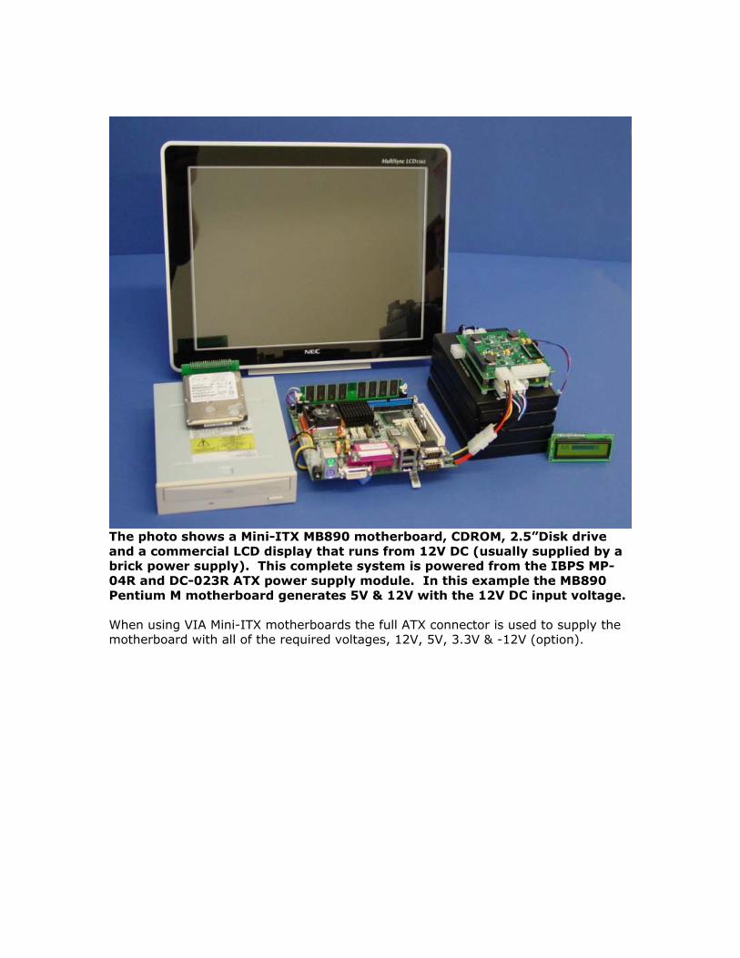
The photo shows a Mini-ITX MB890 motherboard, CDROM, 2.5”Disk drive and a commercial LCD display that runs from 12V DC (usually supplied by a brick power supply). This complete system is powered from the IBPS MP-04R and DC-023R ATX power supply module. In this example the MB890 Pentium M motherboard generates 5V & 12V with the 12V DC input voltage. When using VIA Mini-ITX motherboards the full ATX connector is used to supply the motherboard with all of the required voltages, 12V, 5V, 3.3V & -12V (option).

6.5 Large System The CB-04 System Controller Module enables the user to tie four MP/XP-04 or MP/XP-08 controllers together to form a single point of control. In the case of four XP/MP-08R’s, up to 32 Smart battery packs are view-able, providing a single RS-232 data stream reporting system status to a host system. The shutdown policy will be across the complete group of packs, the DC-DC shutdown signal will then be a common point. As an example, you could say when 10 packs reach FULLY_DISCHARGED shutdown. When the first 10 packs of a group of 32 reach fully charged the controller will shut down the DC-023R and the load on the battery packs.
The photo shows the MP-08R and eight battery packs in a stack. This stack is a basic building block for larger systems. This photo shows the DC converter that will be used to charge the battery packs. This can be any regulated DC converter that supplies the correct charge voltage and current for the system. Eight of these stacks create a 6080 Watt-hour battery system and can be combined with DC-DC converters for system level output voltages that are regulated.

The photo shows the MP-04R and four battery packs that can be combined in large groups to create very large battery Cluster systems in the 10K watt-hour range and above. The advantage of the MP-04R in some cases is that it stacks better into tighter spaces. The LCD display is just shown as an example.
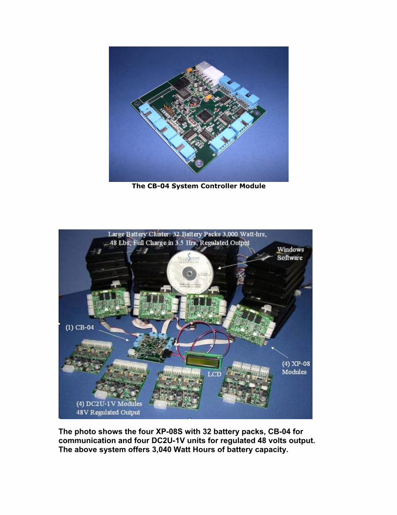
The CB-04 System Controller Module
The photo shows the four XP-08S with 32 battery packs, CB-04 for communication and four DC2U-1V units for regulated 48 volts output. The above system offers 3,040 Watt Hours of battery capacity.
Section 7 7.0 Software
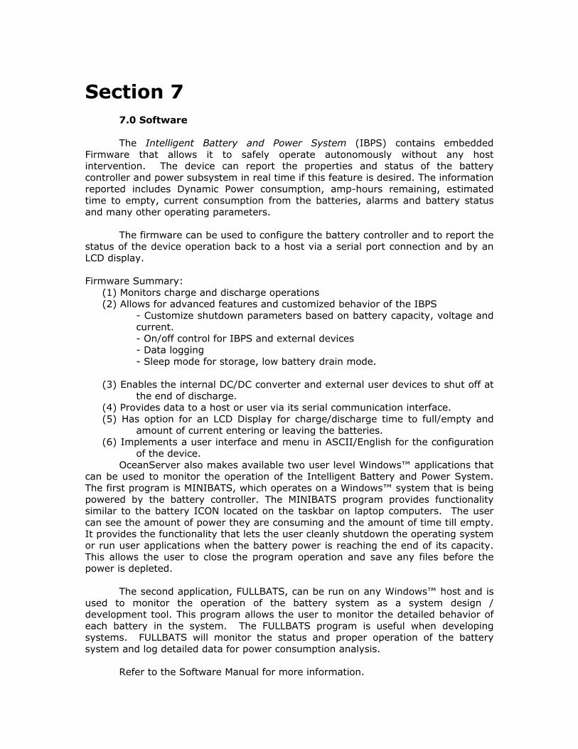
The Intelligent Battery and Power System (IBPS) contains embedded Firmware that allows it to safely operate autonomously without any host intervention. The device can report the properties and status of the battery controller and power subsystem in real time if this feature is desired. The information reported includes Dynamic Power consumption, amp-hours remaining, estimated time to empty, current consumption from the batteries, alarms and battery status and many other operating parameters. The firmware can be used to configure the battery controller and to report the status of the device operation back to a host via a serial port connection and by an LCD display. Firmware Summary:
(1) Monitors charge and discharge operations (2) Allows for advanced features and customized behavior of the IBPS
- Customize shutdown parameters based on battery capacity, voltage and current.
- On/off control for IBPS and external devices - Data logging - Sleep mode for storage, low battery drain mode. (3) Enables the internal DC/DC converter and external user devices to shut off at
the end of discharge. (4) Provides data to a host or user via its serial communication interface. (5) Has option for an LCD Display for charge/discharge time to full/empty and
amount of current entering or leaving the batteries. (6) Implements a user interface and menu in ASCII/English for the configuration
of the device. OceanServer also makes available two user level Windows™ applications that can be used to monitor the operation of the Intelligent Battery and Power System. The first program is MINIBATS, which operates on a Windows™ system that is being powered by the battery controller. The MINIBATS program provides functionality similar to the battery ICON located on the taskbar on laptop computers. The user can see the amount of power they are consuming and the amount of time till empty. It provides the functionality that lets the user cleanly shutdown the operating system or run user applications when the battery power is reaching the end of its capacity. This allows the user to close the program operation and save any files before the power is depleted. The second application, FULLBATS, can be run on any Windows™ host and is used to monitor the operation of the battery system as a system design / development tool. This program allows the user to monitor the detailed behavior of each battery in the system. The FULLBATS program is useful when developing systems. FULLBATS will monitor the status and proper operation of the battery system and log detailed data for power consumption analysis. Refer to the Software Manual for more information.
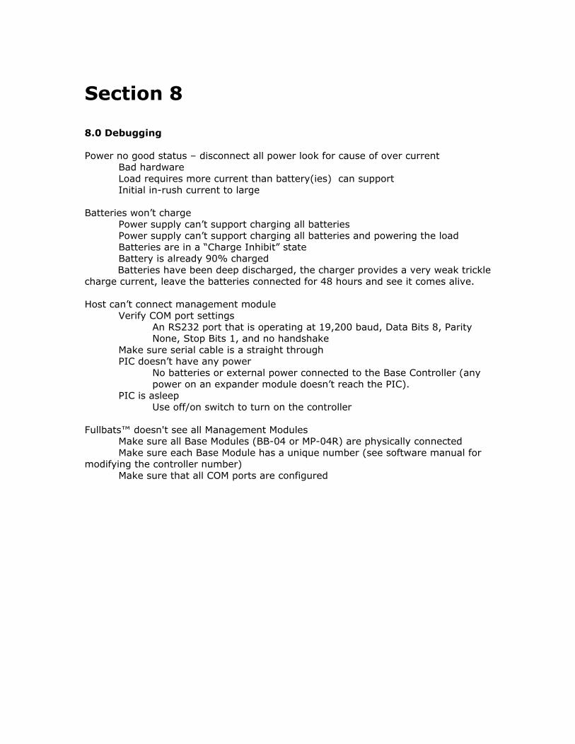
Section 8 8.0 Debugging Power no good status – disconnect all power look for cause of over current
Bad hardware Load requires more current than battery(ies) can support Initial in-rush current to large
Batteries won’t charge Power supply can’t support charging all batteries Power supply can’t support charging all batteries and powering the load Batteries are in a “Charge Inhibit” state Battery is already 90% charged Batteries have been deep discharged, the charger provides a very weak trickle charge current, leave the batteries connected for 48 hours and see it comes alive. Host can’t connect management module Verify COM port settings
An RS232 port that is operating at 19,200 baud, Data Bits 8, Parity None, Stop Bits 1, and no handshake
Make sure serial cable is a straight through PIC doesn’t have any power
No batteries or external power connected to the Base Controller (any power on an expander module doesn’t reach the PIC).
PIC is asleep Use off/on switch to turn on the controller Fullbats™ doesn't see all Management Modules Make sure all Base Modules (BB-04 or MP-04R) are physically connected Make sure each Base Module has a unique number (see software manual for modifying the controller number) Make sure that all COM ports are configured
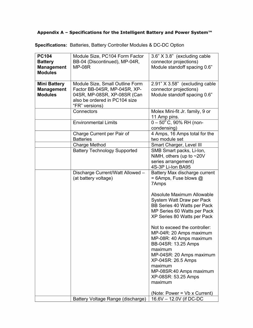
Appendix A – Specifications for the Intelligent Battery and Power System™ Specifications: Batteries, Battery Controller Modules & DC-DC Option
PC104 Battery Management Modules
Module Size, PC104 Form Factor BB-04 (Discontinued), MP-04R, MP-08R
3.6” X 3.8” (excluding cable connector projections) Module standoff spacing 0.6”
Mini Battery Management Modules
Module Size, Small Outline Form Factor BB-04SR, MP-04SR, XP-04SR, MP-08SR, XP-08SR (Can also be ordered in PC104 size “FR” versions)
2.91” X 3.58” (excluding cable connector projections) Module standoff spacing 0.6”
Connectors Molex Mini-fit Jr. family, 9 or 11 Amp pins.
Environmental Limits 0 – 500 C, 90% RH (non-condensing)
Charge Current per Pair of Batteries
4 Amps, 16 Amps total for the two module set
Charge Method Smart Charger, Level III Battery Technology Supported SMB Smart packs, Li-Ion,
NiMH, others (up to ~20V series arrangement) 4S-3P Li-Ion BA95
Discharge Current/Watt Allowed – (at battery voltage)
Battery Max discharge current = 6Amps, Fuse blows @ 7Amps Absolute Maximum Allowable System Watt Draw per Pack BB Series 40 Watts per Pack MP Series 60 Watts per Pack XP Series 80 Watts per Pack Not to exceed the controller: MP-04R: 20 Amps maximum MP-08R: 40 Amps maximum BB-04SR: 13.25 Amps maximum MP-04SR: 20 Amps maximum XP-04SR: 26.5 Amps maximum MP-08SR:40 Amps maximum XP-08SR: 53.25 Amps maximum (Note: Power = Vb x Current)
Battery Voltage Range (discharge) 16.6V – 12.0V (if DC-DC

present) Battery Self Heating Function of the current draw
on the battery pack. At low current draws say less than 1.5 A you can stack the packs on each other.
Charge DC Voltage Pack charge V + 1V and < 24V. Power supplies offered are at 18.5V and 20V.
Battery Management Modules
Module Cooling Still air cooling is sufficient for lower power levels, thermocouple points; FETS case < 1100C and Inductor cores < 1000C
Charge Current Regulator > 95% conversion efficiency DC-DC Converter (DC-023R)
Maximum Current per Voltage (single DC-DC converter module)
12V @ 7A; 5V @ 10A; 3.3V @10A
Maximum Current, Dual Parallel Configuration DC-023R (two stacked DC-DC modules for increased current)
12V @ 13A; 5V @ 19A; 3.3V @19A
DC-DC Converter (DC-123SR)
Maximum Current per Voltage (single DC-DC converter module) Works with the small outline (BB/MP/XP-xxSR/FR units)
12V @ 12A; 5V @ 10A; 3.3V @10A
Connectors Molex Mini-fit Jr. family, 9 or 11 Amp pins. [Users can build cables using a low cost crimping tool and parts from mouser.com, or digikey.com]
Environmental Limits 00 – 500 C, 90% RH (non-condensing)
Module Size, PC104 Form Factor 3.6” X 3.8” (excluding cable connector projections) Module standoff spacing 0.6”
Output Voltage Regulation 5% On all voltages (ripple and noise < 150mv pp)
Conversion Efficiency > 95% based on current draw Maximum Power 150W (Single module),
260W (Dual module) Module cooling Typically still air cooling is
sufficient, thermocouple points; FETS case < 120C and Inductor cores < 110C
Current Limiting Voltage foldback at ~+10% over current spec.
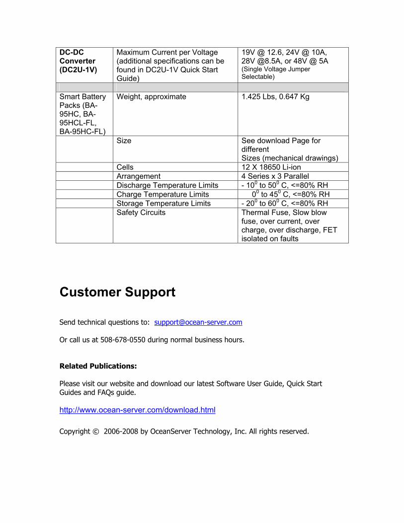
DC-DC Converter (DC2U-1V)
Maximum Current per Voltage (additional specifications can be found in DC2U-1V Quick Start Guide)
19V @ 12.6, 24V @ 10A, 28V @8.5A, or 48V @ 5A (Single Voltage Jumper Selectable)
Smart Battery Packs (BA-95HC, BA-95HCL-FL, BA-95HC-FL)
Weight, approximate 1.425 Lbs, 0.647 Kg
Size See download Page for different Sizes (mechanical drawings)
Cells 12 X 18650 Li-ion Arrangement 4 Series x 3 Parallel Discharge Temperature Limits - 100 to 500 C, <=80% RH Charge Temperature Limits 00 to 450 C, <=80% RH Storage Temperature Limits - 200 to 600 C, <=80% RH Safety Circuits Thermal Fuse, Slow blow
fuse, over current, over charge, over discharge, FET isolated on faults
Customer Support Send technical questions to: [email protected] Or call us at 508-678-0550 during normal business hours. Related Publications: Please visit our website and download our latest Software User Guide, Quick Start Guides and FAQs guide. http://www.ocean-server.com/download.html
Copyright © 2006-2008 by OceanServer Technology, Inc. All rights reserved.