Embed Size (px)
Citation preview

IBM Mobile SystemsThinkPad ComputerHardware Maintenance Manual
January 2001
This manual supports:
ThinkPad A21e (MT 2655)
���

NoteBefore using this information and the product itsupports, be sure to read the general informationunder “Notices” on page 115.
First Edition (January 2001)
The following paragraph does not apply to the UnitedKingdom or any country where such provisions areinconsistent with local law:INTERNATIONAL BUSINESS MACHINES CORPORATIONPROVIDES THIS PUBLICATION “AS IS” WITHOUT ANYWARRANTY OF ANY KIND, EITHER EXPRESS ORIMPLIED, INCLUDING, BUT NOT LIMITED TO, THELIMITED WARRANTIES OF MERCHANTABILITY ORFITNESS FOR A PARTICULAR PURPOSE. Some statesdo not allow disclaimer or express or implied warranties incertain transactions; therefore, this statement may notapply to you.
This publication could include technical inaccuracies ortypographical errors. Changes are periodically made to theinformation herein; these changes will be incorporated innew editions of the publication. IBM may makeimprovements or changes to the products or the programsdescribed in this publication at any time.
It is possible that this publication may contain referencesto, or information about, IBM products (machines andprograms), programming, or services that are notannounced in your country. Such references or informationmust not be construed to mean that IBM intends toannounce such IBM products, programming, or services inyour country.
Requests for technical information about IBM productsshould be made to your IBM authorized dealer or your IBMmarketing representative.
© Copyright International Business MachinesCorporation 2001. All rights reserved. Note to U.S.Government Users – Documentation related to restrictedrights – Use, duplication, or disclosure is subject torestrictions set forth in GSA ADP Schedule Contract withIBM Corp.
© Copyright IBM Corp. 2001

Contents
Introduction . . . . . . . . . . . . . 1Important service information . . . . . . . . . 1
Strategy for replacing FRUs . . . . . . . . 1How to use error messages . . . . . . . . 2
Diskette compatibility matrix . . . . . . . . . 2Safety notices: multilingual translations . . . . . . 3Safety information. . . . . . . . . . . . 12
General safety . . . . . . . . . . . . 12Electrical safety . . . . . . . . . . . 13Safety inspection guide . . . . . . . . . 14Handling electrostatic discharge-sensitive devices 15Grounding requirements . . . . . . . . . 16
Laser compliance statement. . . . . . . . . 16
General descriptions . . . . . . . . . . 19Read this first . . . . . . . . . . . . . 19
What to do first: . . . . . . . . . . . 19Related service information . . . . . . . . . 21
Service Web site . . . . . . . . . . . 21Using Recovery CD . . . . . . . . . . 21Passwords . . . . . . . . . . . . . 22Power management . . . . . . . . . . 24
Checkout guide . . . . . . . . . . . . 26Testing the computer . . . . . . . . . . 26Detecting system information with PC-Doctor. . . 28Power system checkout . . . . . . . . . 29
ThinkPad A21e . . . . . . . . . . . . 33Product overview . . . . . . . . . . . . 35
Specifications . . . . . . . . . . . . 35Status indicators . . . . . . . . . . . 36FRU Tests . . . . . . . . . . . . . 38Fn key combinations . . . . . . . . . . 40
Symptom-to-FRU index . . . . . . . . . . 41Numeric error codes . . . . . . . . . . 41Error messages . . . . . . . . . . . 44Beep symptoms . . . . . . . . . . . 45No beep symptoms . . . . . . . . . . 45LCD-related symptoms . . . . . . . . . 46Intermittent problems . . . . . . . . . . 46Undetermined problems . . . . . . . . . 47
FRU replacement notices . . . . . . . . . 47Screw notices . . . . . . . . . . . . 47Retaining serial numbers. . . . . . . . . 48
Removing and replacing a FRU. . . . . . . . 501010 Battery pack. . . . . . . . . . . 511020 Backup battery . . . . . . . . . . 521030 Hard-disk drive . . . . . . . . . . 541040 DIMM . . . . . . . . . . . . 561050 Mini PCI adapter . . . . . . . . . 57
iii

1060 Ultrabay 2000 device . . . . . . . . 601070 Keyboard . . . . . . . . . . . 611080 Keyboard CRU insulator . . . . . . . 661090 Fan assembly . . . . . . . . . . 671100 PC Card slot assembly . . . . . . . 701110 Hinge cover . . . . . . . . . . . 721120 Keyboard bezel . . . . . . . . . . 741130 Speaker . . . . . . . . . . . . 771140 Hard-disk bay . . . . . . . . . . 781150 Ultrabay 2000 slot . . . . . . . . . 801160 System board . . . . . . . . . . 842010 LCD assembly . . . . . . . . . . 862020 Front bezel . . . . . . . . . . . 902030 Inverter card . . . . . . . . . . 922040 LCD panel . . . . . . . . . . . 942050 Sub card. . . . . . . . . . . . 99
Locations . . . . . . . . . . . . . . 101Front view . . . . . . . . . . . . 101Rear view. . . . . . . . . . . . . 102Bottom view . . . . . . . . . . . . 103
Parts list . . . . . . . . . . . . . . 104Overall . . . . . . . . . . . . . 104LCD FRUs . . . . . . . . . . . . 107Keyboard . . . . . . . . . . . . . 110Miscellaneous parts . . . . . . . . . . 111Optional FRUs . . . . . . . . . . . 113Common parts list . . . . . . . . . . 114
Notices . . . . . . . . . . . . . . 115Trademarks . . . . . . . . . . . . 115
iv ThinkPad A21e (MT 2655)

Introduction
Important service information
ImportantDiskette fixes are customer-installable. The diskettefixes are posted on the IBM support site(http://www.pc.ibm.com/support/).
Advise customers to contact the PC CompanyHelpCenter at 800-772-2227 if they need assistancein obtaining or installing any diskette fixes.
Customers in Canada should call IBM HelpPC at800-565-3344 for assistance or downloadinformation.
Strategy for replacing FRUs
Before replacing partsMake sure that all diskette fixes are installed beforereplacing any FRUs listed in this manual.
Use the following strategy to prevent unnecessary FRUreplacement and service expense:v If you are instructed to replace a FRU but the
replacement does not correct the problem, reinstallthe original FRU before you continue.
v Some computers have both a processor board and asystem board. If you are instructed to replace either theprocessor board or the system board, and replacing oneof them does not correct the problem, reinstall thatboard, and then replace the other one.
v If an adapter or device consists of more than one FRU,any of the FRUs may be the cause of the error. Beforereplacing the adapter or device, remove the FRUs, oneby one, to see if the symptoms change. Replace onlythe FRU that changed the symptoms.
1

AttentionThe setup configuration on the computer you areservicing may have been customized. RunningAutomatic Configuration may alter the settings. Notethe current configuration settings (using the ViewConfiguration option); then, when service has beencompleted, verify that those settings remain ineffect.
Strategy for replacing a hard-disk driveAlways try to run a low-level format before replacing ahard-disk drive.
AttentionThe drive startup sequence in the computer you areservicing may have been changed. Be extremelycareful during write operations such as copying,saving, or formatting. If you select an incorrect drive,data or programs can be overwritten.
How to use error messagesUse the error codes displayed on the screen to diagnosefailures. If more than one error code is displayed, begin thediagnosis with the first error code. Whatever causes thefirst error code may also cause false error codes. If noerror code is displayed, see if the error symptom is listedin the Symptom-to-FRU Index for the computer you areservicing.
Diskette compatibility matrix
The compatibility of each of the drives with the diskettesfor it is as follows:
Diskettedrive
Diskettecapacity
Compatibility
3.5-inch 1.0 MB Read and write
2.0 MB Read and write
4.0 MB Not compatible
Important service information
2 ThinkPad A21e (MT 2655)

Safety notices: multilingual translations
In this manual, safety notices appear in English with apage number reference to the appropriate translation inthis section.
The safety notices are provided in English, French,German, Italian, and Spanish, as follows:
Safety notice 1Before the computer is powered-on after FRUreplacement, make sure all screws, springs, andother small parts are in place and are not left looseinside the computer. Verify this by shaking thecomputer and listening for rattling sounds. Metallicparts or metal flakes can cause electrical shorts.
Avant de remettre l’ordinateur sous tension aprèsremplacement d’une unité en clientèle, vérifiez quetous les ressorts, vis et autres pièces sont bien enplace et bien fixées. Pour ce faire, secouez l’unité etassurez-vous qu’aucun bruit suspect ne se produit.Des pièces métalliques ou des copeaux de métalpourraient causer un court-circuit.
Bevor nach einem FRU-Austausch der Computerwieder angeschlossen wird, muß sichergestelltwerden, daß keine Schrauben, Federn oder andereKleinteile fehlen oder im Gehäuse vergessenwurden. Der Computer muß geschüttelt und aufKlappergeräusche geprüft werden. Metallteileoder-splitter können Kurzschlüsse erzeugen.
Prima di accendere l’elaboratore dopo che é stataeffettuata la sostituzione di una FRU, accertarsi chetutte le viti, le molle e tutte le altri parti di piccoledimensioni siano nella corretta posizione e nonsiano sparse all’interno dell’elaboratore. Verificare ciÚÚ scuotendo l’elaboratore e prestando attenzionead eventuali rumori; eventuali parti o pezzettimetallici possono provocare cortocircuiti pericolosi.
Antes de encender el sistema despues de sustituiruna FRU, compruebe que todos los tornillos,muelles y demás piezas pequeñas se encuentranen su sitio y no se encuentran sueltas dentro delsistema. Compruébelo agitando el sistema yescuchando los posibles ruidos que provocarían.Las piezas metálicas pueden causar cortocircuitoseléctricos.
Safety notices
Introduction 3

Safety notice 2
DANGER:
Some standby batteries contain a small amount ofnickel and cadmium. Do not disassemble a standbybattery, recharge it, throw it into fire or water, orshort-circuit it. Dispose of the battery as required bylocal ordinances or regulations. Use only the batteryin the appropriate parts listing. Use of an incorrectbattery can result in ignition or explosion of thebattery.
Certaines batteries de secours contiennent du nickelet du cadmium. Ne les démontez pas, ne lesrechargez pas, ne les exposez ni au feu ni à l’eau.Ne les mettez pas en court- circuit. Pour les mettreau rebut, conformez-vous à la réglementation envigueur. Lorsque vous remplacez la pile desauvegarde ou celle de l’horloge temps réel, veillezà n’utiliser que les modèles cités dans la liste depièces détachées adéquate. Une batterie ou unepile inappropriée risque de prendre feu oud’exploser.
Die Bereitschaftsbatterie, die sich unter demDiskettenlaufwerk befindet, kann geringe MengenNickel und Cadmium enthalten. Sie darf nur durchdie Verkaufsstelle oder den IBM Kundendienstausgetauscht werden. Sie darf nicht zerlegt,wiederaufgeladen, kurzgeschlossen, oder Feueroder Wasser ausgesetzt werden. Die Batterie kannschwere Verbrennungen oder Verätzungenverursachen. Bei der Entsorgung die örtlichenBestimmungen für Sondermüll beachten. BeimErsetzen der Bereitschafts-oder Systembatterie nurBatterien des Typs verwenden, der in derErsatzteilliste aufgeführt ist. Der Einsatz falscherBatterien kann zu Entzündung oder Explosionführen.
(continued)
Safety notices
4 ThinkPad A21e (MT 2655)

Continuation of Safety notice 2
DANGER:
Alcune batterie di riserva contengono una piccolaquantità di nichel e cadmio. Non smontarle,ricaricarle, gettarle nel fuoco o nell’acqua nécortocircuitarle. Smaltirle secondo la normativa invigore (DPR 915/82, successive disposizioni edisposizioni locali). Quando si sostituisce la batteriadell’RTC (real time clock) o la batteria di supporto,utilizzare soltanto i tipi inseriti nell’appropriatoCatalogo parti. L’impiego di una batteria non adattapotrebbe determinare l’incendio o l’esplosione dellabatteria stessa.
Algunas baterías de reserva contienen una pequeñacantidad de níquel y cadmio. No las desmonte, nirecargue, ni las eche al fuego o al agua ni lascortocircuite. Deséchelas tal como dispone lanormativa local. Utilice sólo baterías que seencuentren en la lista de piezas. La utilización deuna batería no apropiada puede provocar la ignicióno explosión de la misma.
Safety notices
Introduction 5

Safety notice 3
DANGER:
The battery pack contains small amounts of nickel.Do not disassemble it, throw it into fire or water, orshort-circuit it. Dispose of the battery pack asrequired by local ordinances or regulations. Useonly the battery in the appropriate parts listing whenreplacing the battery pack. Use of an incorrectbattery can result in ignition or explosion of thebattery.
La batterie contient du nickel. Ne la démontez pas,ne l’exposez ni au feu ni à l’eau. Ne la mettez pasen court- circuit. Pour la mettre au rebut,conformez-vous à la réglementation en vigueur.Lorsque vous remplacez la batterie, veillez àn’utiliser que les modèles cités dans la liste depièces détachées adéquate. En effet, une batterieinappropriée risque de prendre feu ou d’exploser.
Akkus enthalten geringe Mengen von Nickel. Siedürfen nicht zerlegt, wiederaufgeladen,kurzgeschlossen, oder Feuer oder Wasserausgesetzt werden. Bei der Entsorgung die örtlichenBestimmungen für Sondermüll beachten. BeimErsetzen der Batterie nur Batterien des Typsverwenden, der in der Ersatzteilliste aufgeführt ist.Der Einsatz falscher Batterien kann zu Entzündungoder Explosion führen.
La batteria contiene piccole quantità di nichel. Nonsmontarla, gettarla nel fuoco o nell’acqua nécortocircuitarla. Smaltirla secondo la normativa invigore (DPR 915/82, successive disposizioni edisposizioni locali). Quando si sostituisce la batteria,utilizzare soltanto i tipi inseriti nell’appropriatoCatalogo parti. L’impiego di una batteria non adattapotrebbe determinare l’incendio o l’esplosione dellabatteria stessa.
Las baterías contienen pequeñas cantidades deníquel. No las desmonte, ni recargue, ni las eche alfuego o al agua ni las cortocircuite. Deséchelas talcomo dispone la normativa local. Utilice sólobaterías que se encuentren en la lista de piezas alsustituir la batería. La utilización de una batería noapropiada puede provocar la ignición o explosión dela misma.
Safety notices
6 ThinkPad A21e (MT 2655)
Safety notice 4
DANGER:
The lithium battery can cause a fire, an explosion,or a severe burn. Do not recharge it, remove itspolarized connector, disassemble it, heat it above100°C (212°F), incinerate it, or expose its cellcontents to water. Dispose of the battery as requiredby local ordinances or regulations. Use only thebattery in the appropriate parts listing. Use of anincorrect battery can result in ignition or explosion ofthe battery.
La pile de sauvegarde contient du lithium. Elleprésente des risques d’incendie, d’explosion ou debrûlures graves. Ne la rechargez pas, ne retirez passon connecteur polarisé et ne la démontez pas. Nel’exposez pas à une temperature supérieure à100°C, ne la faites pas brûler et n’en exposez pasle contenu à l’eau. Mettez la pile au rebutconformément à la réglementation en vigueur. Unepile inappropriée risque de prendre feu oud’exploser.
Die Systembatterie ist eine Lithiumbatterie. Sie kannsich entzünden, explodieren oder schwereVerbrennungen hervorrufen. Batterien dieses Typsdürfen nicht aufgeladen, zerlegt, über 100 C erhitztoder verbrannt werden. Auch darf ihr Inhalt nicht mitWasser in Verbindung gebracht oder der zurrichtigen Polung angebrachte Verbindungssteckerentfernt werden. Bei der Entsorgung die örtlichenBestimmungen für Sondermüll beachten. BeimErsetzen der Batterie nur Batterien des Typsverwenden, der in der Ersatzteilliste aufgeführt ist.Der Einsatz falscher Batterien kann zu Entzündungoder Explosion führen.
La batteria di supporto e una batteria al litio e puoincendiarsi, esplodere o procurare gravi ustioni.Evitare di ricaricarla, smontarne il connettorepolarizzato, smontarla, riscaldarla ad unatemperatura superiore ai 100 gradi centigradi,incendiarla o gettarla in acqua. Smaltirla secondo lanormativa in vigore (DPR 915/82, successivedisposizioni e disposizioni locali). L’impiego di unabatteria non adatta potrebbe determinare l’incendioo l’esplosione della batteria stessa.
(continued)
Safety notices
Introduction 7

Continuation of Safety notice 4
DANGER:
La batería de repuesto es una batería de litio ypuede provocar incendios, explosiones oquemaduras graves. No la recargue, ni quite elconector polarizado, ni la desmonte, ni caliente porencima de los 100°C (212°F), ni la incinere niexponga el contenido de sus celdas al agua.Deséchela tal como dispone la normativa local.
Safety notices
8 ThinkPad A21e (MT 2655)

Safety notice 5If the LCD breaks and the fluid from inside the LCDgets into your eyes or on your hands, immediatelywash the affected areas with water for at least 15minutes. Seek medical care if any symptoms fromthe fluid are present after washing.
Si le panneau d’affichage à cristaux liquides sebrise et que vous recevez dans les yeux ou sur lesmains une partie du fluide, rincez-les abondammentpendant au moins quinze minutes. Consultez unmédecin si des symptômes persistent après lelavage.
Die Leuchtstoffröhre im LCD-Bildschirm enthältQuecksilber. Bei der Entsorgung die örtlichenBestimmungen für Sondermüll beachten. DerLCD-Bildschirm besteht aus Glas und kannzerbrechen, wenn er unsachgemäß behandelt wirdoder der Computer auf den Boden fällt. Wenn derBildschirm beschädigt ist und die darin befindlicheFlüssigkeit in Kontakt mit Haut und Augen gerät,sollten die betroffenen Stellen mindestens 15Minuten mit Wasser abgespült und beiBeschwerden anschließend ein Arzt aufgesuchtwerden.
Nel caso che caso l’LCD si dovesse rompere ed illiquido in esso contenuto entrasse in contatto con gliocchi o le mani, lavare immediatamente le partiinteressate con acqua corrente per almeno 15minuti; poi consultare un medico se i sintomidovessero permanere.
Si la LCD se rompe y el fluido de su interior entraen contacto con sus ojos o sus manos, laveinmediatamente las áreas afectadas con aguadurante 15 minutos como mínimo. Obtenga atenciónmedica si se presenta algún síntoma del fluidodespues de lavarse.
Safety notices
Introduction 9

Safety notice 6To avoid shock, do not remove the plastic cover thatprotects the lower part of the inverter card.
Afin d’éviter tout risque de choc électrique, neretirez pas le cache en plastique protégeant lapartie inférieure de la carte d’alimentation.
Aus Sicherheitsgründen die Kunststoffabdeckung,die den unteren Teil der Spannungswandlerplatineumgibt, nicht entfernen.
Per evitare scosse elettriche, non rimuovere lacopertura in plastica che avvolge la parte inferioredella scheda invertitore.
Para evitar descargas, no quite la cubierta deplástico que rodea la parte baja de la tarjetainvertida.
Safety notice 7Though the main batteries have low voltage, ashorted or grounded battery can produce enoughcurrent to burn personnel or combustible materials.
Bien que le voltage des batteries principales soitpeu élevé, le court-circuit ou la mise à la massed’une batterie peut produire suffisamment decourant pour brûler des matériaux combustibles oucauser des brûlures corporelles graves.
Obwohl Hauptbatterien eine niedrige Spannunghaben, können sie doch bei Kurzschluß oderErdung genug Strom abgeben, um brennbareMaterialien zu entzünden oder Verletzungen beiPersonen hervorzurufen.
Sebbene le batterie di alimentazione siano a bassovoltaggio, una batteria in corto circuito o a massapuò fornire corrente sufficiente da bruciare materialicombustibili o provocare ustioni ai tecnici dimanutenzione.
Aunque las baterías principales tienen un voltajebajo, una batería cortocircuitada o con contacto atierra puede producir la corriente suficiente comopara quemar material combustible o provocarquemaduras en el personal.
Safety notices
10 ThinkPad A21e (MT 2655)

Safety notice 8Before removing any FRU, power off the computer,unplug all power cords from electrical outlets,remove the battery pack, and then disconnect anyinterconnecting cables.
Avant de retirer une unité remplaçable en clientèle,mettez le système hors tension, débranchez tousles cordons d’alimentation des socles de prise decourant, retirez la batterie et déconnectez tous lescordons d’interface.
Die Stromzufuhr muß abgeschaltet, alle Stromkabelaus der Steckdose gezogen, der Akku entfernt undalle Verbindungskabel abgenommen sein, bevoreine FRU entfernt wird.
Prima di rimuovere qualsiasi FRU, spegnere ilsistema, scollegare dalle prese elettriche tutti i cavidi alimentazione, rimuovere la batteria e poiscollegare i cavi di interconnessione.
Antes de quitar una FRU, apague el sistema,desenchufe todos los cables de las tomas decorriente eléctrica, quite la batería y, a continuación,desconecte cualquier cable de conexión entredispositivos.
Safety notices
Introduction 11

Safety information
The following section contains the safety information thatyou need to be familiar with before servicing an IBMmobile computer.
General safetyFollow these rules to ensure general safety:v Observe good housekeeping in the area of the
machines during and after maintenance.v When lifting any heavy object:
1. Ensure you can stand safely without slipping.2. Distribute the weight of the object equally between
your feet.3. Use a slow lifting force. Never move suddenly or
twist when you attempt to lift.4. Lift by standing or by pushing up with your leg
muscles; this action removes the strain from themuscles in your back. Do not attempt to lift anyobjects that weigh more than 16 kg (35 lb) or objectsthat you think are too heavy for you.
v Do not perform any action that causes hazards to thecustomer, or that makes the equipment unsafe.
v Before you start the machine, ensure that other servicerepresentatives and the customer’s personnel are not ina hazardous position.
v Place removed covers and other parts in a safe place,away from all personnel, while you are servicing themachine.
v Keep your toolcase away from walk areas so that otherpeople will not trip over it.
v Do not wear loose clothing that can be trapped in themoving parts of a machine. Make sure that your sleevesare fastened or rolled up above your elbows. If your hairis long, fasten it.
v Insert the ends of your necktie or scarf inside clothing orfasten it with a nonconductive clip, approximately 8centimeters (3 inches) from the end.
v Do not wear jewelry, chains, metal-frame eyeglasses, ormetal fasteners for your clothing.
Attention: Metal objects are good electrical conductors.v Wear safety glasses when you are hammering, drilling,
soldering, cutting wire, attaching springs, using solvents,or working in any other conditions that might behazardous to your eyes.
v After service, reinstall all safety shields, guards, labels,and ground wires. Replace any safety device that isworn or defective.
v Reinstall all covers correctly before returning themachine to the customer.
Safety information
12 ThinkPad A21e (MT 2655)

Electrical safetyObserve the following rules when working on electricalequipment.
ImportantUse only approved tools and test equipment. Somehand tools have handles covered with a softmaterial that does not insulate you when workingwith live electrical currents.
Many customers have, near their equipment, rubberfloor mats that contain small conductive fibers todecrease electrostatic discharges. Do not use thistype of mat to protect yourself from electrical shock.
v Find the room emergency power-off (EPO) switch,disconnecting switch, or electrical outlet. If an electricalaccident occurs, you can then operate the switch orunplug the power cord quickly.
v Do not work alone under hazardous conditions or nearequipment that has hazardous voltages.
v Disconnect all power before:– Performing a mechanical inspection– Working near power supplies– Removing or installing main units
v Before you start to work on the machine, unplug thepower cord. If you cannot unplug it, ask the customer topower-off the wall box that supplies power to themachine and to lock the wall box in the off position.
v If you need to work on a machine that has exposedelectrical circuits, observe the following precautions:– Ensure that another person, familiar with the
power-off controls, is near you.
Attention: Another person must be there to switchoff the power, if necessary.
– Use only one hand when working with powered-onelectrical equipment; keep the other hand in yourpocket or behind your back.
Attention: An electrical shock can occur only whenthere is a complete circuit. By observing the aboverule, you may prevent a current from passing throughyour body.
– When using testers, set the controls correctly anduse the approved probe leads and accessories forthat tester.
– Stand on suitable rubber mats (obtained locally, ifnecessary) to insulate you from grounds such asmetal floor strips and machine frames.
Observe the special safety precautions when you workwith very high voltages; these instructions are in the
Safety information
Introduction 13

safety sections of maintenance information. Useextreme care when measuring high voltages.
v Regularly inspect and maintain your electrical hand toolsfor safe operational condition.
v Do not use worn or broken tools and testers.v Never assume that power has been disconnected from
a circuit. First, check that it has been powered off.v Always look carefully for possible hazards in your work
area. Examples of these hazards are moist floors,nongrounded power extension cables, power surges,and missing safety grounds.
v Do not touch live electrical circuits with the reflectivesurface of a plastic dental mirror. The surface isconductive; such touching can cause personal injury andmachine damage.
v Do not service the following parts with the power onwhen they are removed from their normal operatingplaces in a machine:– Power supply units– Pumps– Blowers and fans– Motor generators
and similar units. (This practice ensures correctgrounding of the units.)
v If an electrical accident occurs:– Use caution; do not become a victim yourself.– Switch off power.– Send another person to get medical aid.
Safety inspection guideThe purpose of this inspection guide is to assist you inidentifying potentially unsafe conditions. As each machinewas designed and built, required safety items wereinstalled to protect users and service personnel from injury.This guide addresses only those items. You should usegood judgment to identify potential safety hazards due toattachment of non-IBM features or options not covered bythis inspection guide.
If any unsafe conditions are present, you must determinehow serious the apparent hazard could be and whetheryou can continue without first correcting the problem.
Consider these conditions and the safety hazards theypresent:v Electrical hazards, especially primary power (primary
voltage on the frame can cause serious or fatalelectrical shock)
v Explosive hazards, such as a damaged CRT face or abulging capacitor
v Mechanical hazards, such as loose or missing hardware
Safety information
14 ThinkPad A21e (MT 2655)

To determine whether there are any potentially unsafeconditions, use the following checklist at the beginning ofevery service task. Begin the checks with the power off,and the power cord disconnected.
Checklist:1. Check exterior covers for damage (loose, broken, or
sharp edges).2. Power-off the computer. Disconnect the power cord.3. Check the power cord for:
a. A third-wire ground connector in good condition.Use a meter to measure third-wire groundcontinuity for 0.1 ohm or less between the externalground pin and frame ground.
b. The power cord should be the type specified in theparts list.
c. Insulation must not be frayed or worn.4. Remove the cover.5. Check for any obvious non-IBM alterations. Use good
judgment as to the safety of any non-IBM alterations.6. Check inside the unit for any obvious unsafe
conditions, such as metal filings, contamination, wateror other liquids, or signs of fire or smoke damage.
7. Check for worn, frayed, or pinched cables.8. Check that the power-supply cover fasteners (screws
or rivets) have not been removed or tampered with.
Handling electrostaticdischarge-sensitive devicesAny computer part containing transistors or integratedcircuits (ICs) should be considered sensitive to electrostaticdischarge (ESD). ESD damage can occur when there is adifference in charge between objects. Protect against ESDdamage by equalizing the charge so that the machine, thepart, the work mat, and the person handling the part are allat the same charge.
Notes1. Use product-specific ESD procedures when they
exceed the requirements noted here.2. Make sure that the ESD protective devices you
use have been certified (ISO 9000) as fullyeffective.
When handling ESD-sensitive parts:v Keep the parts in protective packages until they are
inserted into the product.v Avoid contact with other people.v Wear a grounded wrist strap against your skin to
eliminate static on your body.
Safety information
Introduction 15

v Prevent the part from touching your clothing. Mostclothing is insulative and retains a charge even whenyou are wearing a wrist strap.
v Use the black side of a grounded work mat to provide astatic-free work surface. The mat is especially usefulwhen handling ESD-sensitive devices.
v Select a grounding system, such as those listed below,to provide protection that meets the specific servicerequirement.
NoteThe use of a grounding system is desirable butnot required to protect against ESD damage.
– Attach the ESD ground clip to any frame ground,ground braid, or green-wire ground.
– Use an ESD common ground or reference pointwhen working on a double-insulated orbattery-operated system. You can use coax orconnector-outside shells on these systems.
– Use the round ground-prong of the AC plug onAC-operated computers.
Grounding requirementsElectrical grounding of the computer is required foroperator safety and correct system function. Propergrounding of the electrical outlet can be verified by acertified electrician.
Laser compliance statement
Some IBM Personal Computer models are equipped fromthe factory with a CD-ROM drive or DVD drive. CD-ROMdrives or DVD drives are also sold separately as options.The CD-ROM drive or DVD drive is a laser product. TheCD-ROM drive or DVD drive is certified in the U.S. toconform to the requirements of the Department of Healthand Human Services 21 Code of Federal Regulations(DHHS 21 CFR) Subchapter J for Class 1 laser products.Elsewhere, the drive is certified to conform to therequirements of the International ElectrotechnicalCommission (IEC) 825 and CENELEC EN 60 825 forClass 1 laser products.
Safety information
16 ThinkPad A21e (MT 2655)

When a CD-ROM drive or DVD drive is installed, note thefollowing:
CAUTION:
Use of controls or adjustments or performanceof procedures other than those specifiedherein might result in hazardous radiationexposure.
O uso de controles, ajustes ou desempenho deprocedimentos diferentes daqueles aquiespecificados pode resultar em perigosaexposição à radiação.
Pour éviter tout risque d’exposition au rayonlaser, respectez les consignes de réglage etd’utilisation des commandes, ainsi que lesprocédures décrites.
Werden Steuer- und Einstellelemente andersals hier festgesetzt verwendet, kanngefährliche Laserstrahlung auftreten.
L’utilizzo di controlli, regolazioni o l’esecuzionedi procedure diverse da quelle specificatepossono provocare l’esposizione a.
El uso de controles o ajustes o la ejecución deprocedimientos distintos de los aquíespecificados puede provocar la exposición aradiaciones peligrosas.
Opening the CD-ROM drive or DVD drive could result inexposure to hazardous laser radiation. There are noserviceable parts inside the CD-ROM drive or DVD drive.Do not open.
Laser compliance statement
Introduction 17
Some CD-ROM drives or DVD drives contain anembedded Class 3A or Class 3B laser diode. Note thefollowing:
DANGER:
Emits visible and invisible laser radiation whenopen. Do not stare into the beam, do not viewdirectly with optical instruments, and avoiddirect exposure to the beam.
Radiação por raio laser ao abrir. Não olhe fixono feixe de luz, não olhe diretamente por meiode instrumentos óticos e evite exposição diretacom o feixe de luz.
Rayonnement laser si carter ouvert. Évitez defixer le faisceau, de le regarder directementavec des instruments optiques, ou de vousexposer au rayon.
Laserstrahlung bei geöffnetem Gerät. Nichtdirekt oder über optische Instrumente in denLaserstrahl sehen und den Strahlungsbereichmeiden.
Kinyitáskor lézersugár ! Ne nézzen bele seszabad szemmel, se optikai eszközökkel.Kerülje a sugárnyalábbal való érintkezést !
Aprendo l’unità vengono emesse radiazionilaser. Non fissare il fascio, non guardarlodirettamente con strumenti ottici e evitarel’esposizione diretta al fascio.
Radiación láser al abrir. No mire fijamente niexamine con instrumental óptico el haz de luz.Evite la exposición directa al haz.
Laser compliance statement
18 ThinkPad A21e (MT 2655)

General descriptions
This chapter includes descriptions for any ThinkPad modelthat has the PC-Doctor DOS diagnostics program. Somedescriptions might not apply to your particular computer.
Read this first
Before you go to the checkout guide, be sure to read thissection.
Important notesv Only certified trained personnel should
service the computer.v Read the entire FRU removal and replacement
page before replacing any FRU.v Use new nylon-coated screws when you
replace FRUs.v Be extremely careful during such write
operations as copying, saving, or formatting.Drives in the computer that you are servicingsequence might have been altered. If you selectan incorrect drive, data or programs might beoverwritten.
v Replace FRUs only for the correct model.When you replace a FRU, make sure the modelof the machine and the FRU part number arecorrect by referring to the FRU parts list.
v A FRU should not be replaced because of asingle, unreproducible failure. Single failurescan occur for a variety of reasons that havenothing to do with a hardware defect, such ascosmic radiation, electrostatic discharge, orsoftware errors. Consider replacing a FRU onlywhen a problem recurs. If you suspect that aFRU is defective, clear the error log and run thetest again. If the error does not recur, do notreplace the FRU.
v Be careful not to replace a nondefective FRU.
What to do first:When you do return a FRU, you must include the followinginformation in the parts exchange form or parts return formthat you attach to it:__ 1. Name and phone number of servicer__ 2. Date of service__ 3. Date on which the machine failed__ 4. Date of purchase__ 5. Failure symptoms, error codes appearing on the
display, and beep symptoms
19
__ 6. Procedure index and page number in which thefailing FRU was detected
__ 7. Failing FRU name and part number__ 8. Machine type, model number, and serial number__ 9. Customer’s name and address
Note for warrantyDuring the warranty period, the customer may beresponsible for repair costs if the computer damage wascaused by misuse, accident, modification, unsuitablephysical or operating environment, or impropermaintenance by the customer. The following list providessome common items that are not covered under warrantyand some symptoms that might indicate that the systemwas subjected to stress beyond normal use.
Before checking problems with the computer, determinewhether the damage is covered under the warranty byreferring to the following:
The following are not covered under warranty:v LCD panel cracked from the application of excessive
force or from being droppedv Scratched (cosmetic) partsv Distortion, deformation or discoloration of the cosmetic
partsv Cracked or broken plastic parts, broken latches, broken
pins, or broken connectors caused by excessive forcev Damage caused by liquid spilled into the systemv Damage caused by the improper insertion of a PC Card
or the installation of an incompatible cardv Damage caused by foreign material in the diskette drivev Diskette drive damage caused by pressure on the
diskette drive cover or by the insertion of a diskette withmultiple labels
v Damaged or bent diskette eject buttonv Fuses blown by attachment of a nonsupported devicev Forgotten computer password (making the computer
unusable)v Sticky keys caused by spilling a liquid onto the keyboard
The following symptoms might indicate damagecaused by nonwarranted activities:v Missing parts might be a symptom of unauthorized
service or modification.v If the spindle of a hard disk drive becomes noisy, it may
have been subjected to excessive force, or dropped.
Read this first
20 ThinkPad A21e (MT 2655)

Related service information
This section provides information about the following:v “Service Web site”v “Using Recovery CD”v “Passwords” on page 22v “Power management” on page 24
Service Web siteWhen the latest maintenance diskette and the systemprogram service diskette are available, a notice will beposted on http://www.pc.ibm.com/partner/infotips/
Using Recovery CDTo create Service Partition and install the preloadedsystem from Recovery CD, do the following;
To create Service Partition [SP]:1. Erase all partitions on the hard-disk drive using FDISK
or similar application.2. Boot with Recovery CD (and boot diskette if required).3. A menu will appear stating “Your computer originally
included a Product Recovery program ... Reinstallthe Product Recovery Program? (Y/N) [ ]”.
Note: If the hard-disk drive contains any partitions, youwill not receive this menu — go to step 1.
4. Enter “Y” and Service Partition will be created andloaded with D2D files.
Note: If you do not want to create Service Partition,press “N”, and then go to step 8.
5. Press “ENTER” at next window to continue.v Service Partition will be created. System will
automatically reboot during this precess.v Recovery process will copy some files to the Service
Partition, PKUNZIP others.v Follow prompts — you may be prompted to change
CDs.v System will reboot when complete, continue to step
6 to install preloaded sysem.
Install preloaded system from CD:6. Boot with Recovery CD (and boot diskette if required)7. If the hard-disk drive is blank, a menu will appear
stating “Your computer originally included aProduct Recovery program ... Reinstall theProduct Recovery Program? (Y/N) [ ]”.v To install Service Patition, go to step 4.v To preload hard-disk drive without installing Service
Partition, press “N”.
Related service information
General descriptions 21

8. If a menu appears asking which operating system toinstall, highlight proper operating system and press“ENTER”.
9. A menu will appear stating “Full Recovery:”. Press“ENTER” to select.
10. Enter “Y” at the three windows which follow.11. Follow prompts to complete Recovery.
PasswordsAs many as three passwords may be needed for anyThinkPad computer: the power-on password (POP), thehard-disk password (HDP), and the supervisor password(SVP).
Exception: If only SVP is installed, the password promptdoes not appear when the operating system isbooted.
When any of these passwords is used, a password promptappears on the screen whenever the computer is turnedon. The computer does not start until the password isentered.
Power-on password:A power-on password (POP) protects the system frombeing powered on by an unauthorized person. Withoutknowing the password, nobody can start the system.
Hard-disk password:There are two hard-disk passwords (HDPs):v User HDP—for the userv Master HDP—for the system administrator, who can use
it to get access to the hard disk even if the user haschanged the user HDP
Note: There are two modes for the HDP: User only andMaster + User. You can enter two HDPs when youselect Master + User.
AttentionIf the master HDP has been forgotten, there is noway to delete it. But you can still get access to thehard disk if you remember the user HDP. If bothuser HDP and master HDP have been forgotten, thepassword cannot be removed and the hard disk willnot be accessible.
Supervisor password:A supervisor password (SVP) protects the systeminformation stored in the IBM BIOS Setup Utility so that
Related service information
22 ThinkPad A21e (MT 2655)

without knowing the password, nobody can change theconfiguration of the computer.
AttentionIf the SVP has been forgotten, there is no way toreset it.
How to remove the power-on passwordTo remove a POP that you have forgotten, do thefollowing:
(A) If SVP is not installed:1. Turn off the computer.2. Remove the battery pack.
For how to remove the battery pack, see “1010 Batterypack” on page 51.
3. Remove the backup battery.
For how to remove the backup battery, see “1020Backup battery” on page 52.
4. Turn on the computer and wait until the POST ends.
After the POST ends, the password prompt does notappear. The POP has been removed.
5. Reinstall the backup battery and the battery pack.
(B) If SVP is installed:1. Turn on the computer by pressing and holding F1.2. Enter the SVP. The IBM BIOS Setup Utility menu
appears.3. Select Password, using the cursor keys to move down
the menu.4. Select Power-On Password.5. Enter the SVP, at the Enter Current Password field.6. When the Enter New Password field opens, leave it
blank and press Enter twice.7. Press Enter in the Changes have been saved window.8. Press F10; then select Yes in the Setup confirmation
window.
How to remove the hard-disk password
AttentionIf User only mode is selected and the user HDP isforgotten, there is no way to reset it.
To remove the user HDP that you have forgotten, do thefollowing:1. Power on the computer by pressing and holding F1.2. Enter the SVP. The IBM BIOS Setup Utility menu
appears.
Related service information
General descriptions 23

3. Select Password, using the cursor keys to move downthe menu.
4. Select Hard-disk x password, where x is the letter ofthe hard-disk drive. A pop-up window opens.
5. Select either User HDP or Master HDP.6. Enter the master HDP; then leave the New Password
field blank and press Enter twice.7. Press F10.8. Select Yes in the Setup Configuration window.
Both user HDP and master HDP have been removed.
Power managementTo reduce power consumption, the computer has threepower management modes: screen blank (standby inWindows 95 and Windows NT) , standby (suspend inWindows 95 and Windows NT), and hibernation.
Screen blank mode:In screen blank mode, the following occurs:v The LCD backlight turns off.v The hard disk drive motor stops.v The speaker is muted.
To enter screen blank mode, press Fn + F3. To end screenblank mode and resume normal operation, press any key.
Standby mode:When the computer enters standby mode, the followingevents occur in addition to what occurs in screen blankmode:v The LCD is powered off.v The hard disk drive motor stops.v The CPU stops.
To enter standby mode , press Fn + F4.
In certain circumstances, the computer goes into standbymode automatically:v If a “suspend time” has been set on the timer, and the
user does not do any operation with the keyboard, theTrackPoint, the hard disk, the parallel connector, or thediskette drive within the time set.
v If the battery indicator blinks orange, indicating that thebattery power is low. (Alternatively, if Hibernate whenbattery becomes low has been selected in the “PowerManagement Properties” window, the computer goesinto hibernation mode.)
Note: Even if you do not set the low-battery alarm, thecharge indicator lets you know that the battery islow, and then the computer enters the power-savingmode automatically. This default low-batterybehavior is independent of the operating system; so
Related service information
24 ThinkPad A21e (MT 2655)

if you have set the low-battery alarm, the computermay not do what you specified. It chooses eitheryour setting or the default setting, whichever isappropriate.
Any one of the following events causes the computer toresume operation from standby mode:v The Fn key is pressed.v The LCD cover is opened.v The ring indicator (RI) is signaled by a serial device or a
PC Card device.v The power switch is turned on.v The resume timer is set. In Windows which has the
Scheduled Tasks, the Scheduled Tasks setting haspriority over the setting in IBM BIOS Setup Utility.
Note: The computer does not accept any inputimmediately after it enters standby mode. Wait afew seconds before taking any action to reenteroperation mode.
Hibernation mode:
Note for Windows NTIf you are using Windows NT in the default format,NTFS, you cannot create a hibernation file. If youwant to use hibernation mode, you will need toreinstall Windows NT with FAT format.
In hibernation mode, the following occurs:v The system status, RAM, VRAM, and setup data are
stored on the hard disk.v The system is powered off.
Notes:The computer cannot enter hibernation mode whenit is powered with ac power and a communicationPC Card is used.
Any one of the following events causes the computer toenter hibernation mode when the hibernation file iscreated:v The Fn + F12 keys are pressed.v The power switch is turned off and the mode is set to
Power switch mode [Hibernation].v The timer conditions are satisfied in suspend mode (for
operating systems other than Windows 98).v A critically low battery condition occurs and the mode is
set to Hibernate when battery becomes low.
Related service information
General descriptions 25

When the power is turned on, the computer leaveshibernation mode and resumes operation. The hibernationfile in the boot record on the hard disk drive is read, andsystem status is restored from the hard-disk drive.
Checkout guide
Use the following procedures as a guide in identifying andcorrecting problems with the ThinkPad computer.
Note: The diagnostic tests are intended to test only IBMproducts. The use of non-IBM products, prototypecards, or modified options can lead to falseindications of errors and invalid system responses.
1. Identify the failing symptoms in as much detail aspossible.
2. Verify the symptoms. Try to re-create the failure byrunning the diagnostic test or by repeating theoperation.
Testing the computerThe ThinkPad computer has a test program calledPC-Doctor DOS (hereafter called PC-Doctor). You candetect errors by running the diagnostics test included inPC-Doctor. This section is an overview of the procedure.For details that depend on model-unique functions, refer to“Product overview” on page 35.
For some possible configurations of the computer,PC-Doctor might not run correctly. To avoid this problem,you need to initialize the computer setup by use of the IBMBIOS Setup Utility before you run PC-Doctor. On the IBMBIOS Setup Utility screen, press F9, Enter, F10, and thenEnter.
Note: When you initialize the computer configuration,some devices are disabled, such as the serial port.If you test one of these devices, you will need toenable it by using PS2.EXE.
PC-Doctor cannot be used to test a device that is in thedocking station, even if the computer supports the dockingstation. To test a USB device, connect it to the USBconnector of the computer. To test the Ultrabay 2000device, install it in the Ultrabay 2000 slot of the computer.
To run the test, do as follows:
Note: In the following procedure, you can select an itemnot only with the arrow keys, but also with theTrackPoint. Instead of pressing Enter, click the leftbutton.
Related service information
26 ThinkPad A21e (MT 2655)

1. Insert the PC-Doctor disk into the diskette drive; thenpower on the computer.
If the computer cannot be powered on, go to “Powersystem checkout” on page 29, and check the powersources.
If an error code appears, go to “Symptom-to-FRUindex” on page 41.
On the first screen, select the model and press Enter.Follow the instructions on the screen.
2. The main panel of PC-Doctor appears.3. Select Diagnostics with the arrow keys, and press
Enter.
A pull-down menu appears. (Its exact form depends onthe model.)
The options on the test menu are as follows:
Diagnostics Interactive Tests
v Run Normal Testv Run Quick Testv CPU/Coprocessorv Systemboardv Video Adapterv Serial Portsv Parallel Portsv Fixed Disksv Diskette Drivesv Other Devicesv ZIP Dirvev Communicationv Memory Test – Fullv Memory Test – Quick
v Keyboardv Videov Internal Speakerv Mousev Joystick Testv Diskettev System Loadv CD-ROM/DVD Testv Stereo Speaker
Notes:v In the Keyboard test in Interactive Tests, the Fn key
is scanned only once. Each key should be held downfor at least 2 seconds; otherwise, it cannot be sensed.
v Video Adapter test supports only the LCD display onThinkPad. Before running PC-Doctor DOS, detach theexternal Monitor.
Checkout guide
General descriptions 27

Diagnostics QuitIn te rac t ive Tests Hardware Info U t i l i t y F1=Help
Run Quick TestRun Normal Test
SystemboardCPU/Coprocessor
Video AdapterSerial Ports
Diskette DrivesFixed DisksParallel Ports
Other DevicesZIP DriveCommunicationMemory Test - FullMemory Test - Quick
Use the cursor keys and ESC to move in menus. Press ENTER to select.
PC-DOCTOR 2.0 Copyright 2000 PC-Doctor, Inc. All Rights Reserved.
4. Run the applicable function test.5. Follow the instructions on the screen. If there is a
problem, PC-Doctor shows messages describing it.6. To exit the test, select Quit — Exit Diag.
To cancel the test, press Esc.
Note: After executing PC-Doctor, check the systemtime/date and reset them if needed.
Detecting system information withPC-DoctorPC-Doctor can detect the following system information:
Hardware Infov System Configurationv Memory Contentsv Physical Disk Drivesv Logical Disk Drivesv VGA Informationv IDE Drive Infov PCI Informationv PNPISA Infov SMBIOS Infov VESA LCD Info
Utilityv Run External Testsv Surface Scan Hard Diskv Benchmark Systemv DOS Shellv Tech Support Formv Battery Rundownv View Test Logv Print Logv Save Logv Full Erase Hard Drivev Quick Erase Hard Drive
Checkout guide
28 ThinkPad A21e (MT 2655)

Power system checkoutTo verify a symptom, do the following:1. Power off the computer.2. Remove the battery pack.3. Connect the ac adapter.4. Check that power is supplied when you power on the
computer.5. Power off the computer.6. Disconnect the ac adapter and install the charged
battery pack.7. Check that the battery pack supplies power when you
power on the computer.
If you suspect a power problem, see the appropriate oneof the following power supply checkouts:v “Checking the ac adapter”v “Checking operational charging” on page 30v “Checking the battery pack” on page 30v “Checking the backup battery” on page 31
Checking the ac adapterYou are here because the computer fails only when the acadapter is used:v If the power problem occurs only when the port
replicator is used, replace the port replicator.v If the power-on indicator does not turn on, check the
power cord of the ac adapter for correct continuity andinstallation.
v If the computer does not charge during operation, go to″Checking operational charging.″
To check the ac adapter, do the following:1. Unplug the ac adapter cable from the computer.2. Measure the output voltage at the plug of the ac
adapter cable. See the following figure:
Pin Voltage (V dc)
1 +15.5 to +17.0
2 Ground
v If the voltage is not correct, replace the ac adapter.v If the voltage is acceptable, do the following:
– Replace the system board.– If the problem persists, go to “Product overview”
on page 35.
Note: Noise from the ac adapter does not always indicatea defect.
Checkout guide
General descriptions 29

Checking operational chargingTo check whether the battery charges properly duringoperation, use a discharged battery pack or a battery packthat has less than 50% of the total power remaining wheninstalled in the computer.
Perform operational charging. If the battery status indicatoror icon does not turn on, remove the battery pack and let itreturn to room temperature. Reinstall the battery pack. Ifthe charge indicator or icon still does not turn on, replacethe battery pack.
If the charge indicator still does not turn on, replace thesystem board. Then reinstall the battery pack. If it is stillnot charged, go to the next section.
Checking the battery packBattery charging does not start until the Power Metershows that less than 95% of the total power remains;under this condition the battery pack can charge to 100%of its capacity. This protects the battery pack from beingovercharged or from having a shortened life.
To check the status of your battery, move your cursor tothe Power Meter icon in the icon tray of the Windowstaskbar and wait for a moment (but do not click), and thepercentage of battery power remaining is displayed. To getdetailed information about the battery, double-click thePower Meter icon.
Note: If the battery pack becomes hot, it may not be ableto charge. Remove it from the computer and leave itat room temperature for a while. After it cools down,reinstall and recharge it.
To check the battery pack, do the following:1. Power off the computer.2. Remove the battery pack and measure the voltage
between battery terminals 1 (+) and 5 (−). See thefollowing figure:
Terminal Voltage (V dc)
1 + 0 to + 12.6
5 Ground (−)
3. for Lithium ion battery;v If the voltage is less than +11.0 V dc, the battery
pack has been discharged.
Checkout guide
30 ThinkPad A21e (MT 2655)

Note: Recharging will take at least 3 hours, even ifthe indicator does not turn on.
If the voltage is still less than +11.0 V dc afterrecharging, replace the battery.
for Nickel metal hydride battery;v If the voltage is less than +8.0 V dc, the battery
pack has been discharged.
Note: Recharging will take at least 3 hours, even ifthe indicator does not turn on.
If the voltage is still less than +8.0 V dc afterrecharging, replace the battery.
4. for Lithium ion battery;v If the voltage is more than +11.0 V dc, measure the
resistance between battery terminals 4 and 5. Theresistance must be 4 to 30 K ohm.
for Nickel metal hydride battery;v If the voltage is more than +8.0 V dc, measure the
resistance between battery terminals 4 and 5. Theresistance must be 4 to 30 K ohm.
If the resistance is not correct, replace the batterypack. If the resistance is correct, replace the systemboard.
Checking the backup batteryDo the following:1. Power off the computer, and unplug the ac adapter
from it.2. Turn the computer upside down.3. Remove the battery pack (see “1010 Battery pack” on
page 51).4. Remove the backup battery (see “Checking the battery
pack” on page 30).5. Measure the voltage of the backup battery. See the
following figure.
Wire Voltage (V dc)
Red +2.5 to +3.2
Black Ground
v If the voltage is correct, replace the system board.v If the voltage is not correct, replace the backup battery.v If the backup battery discharges quickly after
replacement, replace the system board.
Checkout guide
General descriptions 31

Checkout guide
32 ThinkPad A21e (MT 2655)

ThinkPad A21e
Product overview . . . . . . . . . . . . 35Specifications . . . . . . . . . . . . 35Status indicators . . . . . . . . . . . 36FRU Tests . . . . . . . . . . . . . 38Fn key combinations . . . . . . . . . . 40
Symptom-to-FRU index . . . . . . . . . . 41Numeric error codes . . . . . . . . . . 41Error messages . . . . . . . . . . . 44Beep symptoms . . . . . . . . . . . 45No beep symptoms . . . . . . . . . . 45LCD-related symptoms . . . . . . . . . 46Intermittent problems . . . . . . . . . . 46Undetermined problems . . . . . . . . . 47
FRU replacement notices . . . . . . . . . 47Screw notices . . . . . . . . . . . . 47Retaining serial numbers. . . . . . . . . 48
Restoring the serial number of the system unit 49Retaining the UUID . . . . . . . . . 49
Removing and replacing a FRU. . . . . . . . 501010 Battery pack. . . . . . . . . . . 511020 Backup battery . . . . . . . . . . 521030 Hard-disk drive . . . . . . . . . . 541040 DIMM . . . . . . . . . . . . 561050 Mini PCI adapter . . . . . . . . . 571060 Ultrabay 2000 device . . . . . . . . 601070 Keyboard . . . . . . . . . . . 611080 Keyboard CRU insulator . . . . . . . 661090 Fan assembly . . . . . . . . . . 671100 PC Card slot assembly . . . . . . . 701110 Hinge cover . . . . . . . . . . . 721120 Keyboard bezel . . . . . . . . . . 741130 Speaker . . . . . . . . . . . . 771140 Hard-disk bay . . . . . . . . . . 781150 Ultrabay 2000 slot . . . . . . . . . 801160 System board . . . . . . . . . . 842010 LCD assembly . . . . . . . . . . 862020 Front bezel . . . . . . . . . . . 90
12.1-in. LCD . . . . . . . . . . . 9013.3-in. and 14.1-in. LCD . . . . . . . 91
2030 Inverter card . . . . . . . . . . 9212.1-in. LCD . . . . . . . . . . . 9213.3-in. and 14.1-in. LCD . . . . . . . 93
2040 LCD panel . . . . . . . . . . . 9412.1-in. LCD . . . . . . . . . . . 9413.3-in. and 14.1-in. LCD . . . . . . . 96
2050 Sub card. . . . . . . . . . . . 99Locations . . . . . . . . . . . . . . 101
Front view . . . . . . . . . . . . 101Rear view. . . . . . . . . . . . . 102Bottom view . . . . . . . . . . . . 103
33

Parts list . . . . . . . . . . . . . . 104Overall . . . . . . . . . . . . . 104LCD FRUs . . . . . . . . . . . . 107
12.1-in. SVGA TFT . . . . . . . . . 10713.3-in. XGA TFT . . . . . . . . . 10814.1-in. XGA TFT . . . . . . . . . 109
Keyboard . . . . . . . . . . . . . 110Miscellaneous parts . . . . . . . . . . 111Optional FRUs . . . . . . . . . . . 113Common parts list . . . . . . . . . . 114
Tools . . . . . . . . . . . . . 114Power cords (system) . . . . . . . . 114
Notices . . . . . . . . . . . . . . 115Trademarks . . . . . . . . . . . . 115
34 ThinkPad A21e (MT 2655)

Product overview
This section presents the following product-uniqueinformation:v “Specifications”v “Status indicators” on page 36v “FRU Tests” on page 38v “Fn key combinations” on page 40
SpecificationsThe following table lists the specifications of the ThinkPadA21e series:
Feature Description
Processor v Intel® Celeron® processor 700 MHzv Intel® Celeron® processor 650 MHz
Bus architecture PCI Bus
Memory (standard) 64 MB (SO-DIMM × 2)
Memory (optional) 64 MB or 128 MB DIMM card (maximum of256 MB)
CMOS RAM 242 bytes
Display v 12.1-inch, 16M colors, SVGA (800×600resolution) TFT color LCD
v 13.3-inch, 16M colors, XGA (1024×768resolution) TFT color LCD
v 14.1-inch, 16M colors, XGA (1024×768resolution) TFT color LCD
Hard-disk drive v 10.0 GB, 2.5-inch, IDE interfacev 20.0 GB, 2.5-inch, IDE interface
I/O port v External monitorv Line-inv Headphonev Microphonev Parallel or diskette drivev Port replicator connectorv Serialv Universal serial bus (USB) connectorv RJ11v RJ45
Internal modem 56.6 Kbps
Audio v Internal speakerv Software control volume
PC Card One Type-III or one Type-II
AC adapter 72-watt type
Bay device 10-24x CD-ROM drive
Product overview
ThinkPad A21e 35

Status indicatorsThe system status indicators show the status of thecomputer, as follows:
Indicator Meaning
�1� Drive in use Green: Data is being read from orwritten to the hard-disk drive,the diskette drive, or the drivein the Ultrabay 2000. Whenthis indicator is on, do not putthe computer into standbymode or turn off the computer.
Note: Do not move the system while theGreen drive in use light is on. Suddenphysical shock could cause drive errors.
�2� Num lock Green: The numeric keypad on thekeyboard is enabled. To enableor disable the keypad, pressand hold the Fn key whilepressing the NumLk key.
�3� Caps lock Green: Caps Lock mode is enabled.To enable or disable CapsLock mode, press Fn + CapsLock key.
(continued)
Product overview
36 ThinkPad A21e (MT 2655)

Indicator Meaning
�4� Scroll lock Green: Scroll Lock mode is enabled.Arrow keys can be useed asscreen-scroll function keys, butnot to move the cursor. Toenable or disable Scroll Lockmode, press Fn + ScrLk key.Not all application programssupport this function.
�5� Power on Green: This indicator stays lightedwhenever the computer is on.If the power-on indicator is onand the standby indicator is off,the system is ready to use. Ifboth the power-on indicatorand the standby indicator areon, you can use the computerafter it rerurns from thestandby mode and the standbyindicator goes off.
�6� Battery Green: The battery is fully charged.Blinking green:
The battery has enough powerto operate, but is beingcharged.
Orange: The battery power is low. Thebattery is to being charged.
Blinking orange:The battery needs to becharged. when the indicatorstarts blinking orange, thecomputer beeps three times.
�7� Standby status Green: The computer is in standbymode.
Blinking green:The computer is enteringstandby mode or hibernationmode, or is resuming normaloperation. This indicator doesnot blink in Windows 98,Windows 2000 and WindowsMe.
Product overview
ThinkPad A21e 37

FRU TestsThe following table shows the test for each FRU.
FRU Applicable test
System board 1. Diagnostics --> CPU/Coprocessor2. Diagnostics --> Systemboard
Power Diagnostics --> Other Devices --> IBM ACAdapter, IBM Battery 1
LCD unit 1. Diagnostics --> Video Adapter2. Interactive Tests --> Video
Modem 1. Make sure the modem is set up correctly.2. Replace the modem jack and the modem
card in turn, and run the following tests inDiagnostics --> Communication:a. Lucent Modem (M2) Loopbackb. Lucent Modem (M2) Dialtone/DTMc. Intel Modem Registerd. Intel Modem Loopback/DTMFe. Intel SP Modem Registerf. Intel SP Modem Loopback/DTMFg. 3Com MiniPCI Modem Testh. 3Com MiniPCI Dialtone Test
Audio 1. Interactive Tests --> Internal Speaker2. Interactive Tests --> Stereo Speaker3. Diagnostics --> Other Devices --> Crystal
SoundFusion™ Test
Speaker 1. Interactive Tests --> Internal Speaker2. Interactive Tests --> Stereo Speaker
PC Card slots Diagnostics --> Systemboard --> PCMCIA,PCMCIA External Loop
Keyboard 1. Diagnostics --> Systemboard -->Keyboard
2. Interactive Tests --> Keyboard
TrackPoint orpointing device
If the TrackPoint does not work, check theconfiguration in the ThinkPad Configurationprogram. If the TrackPoint is disabled, selectEnable to enable it.
After you use the TrackPoint, the pointer maydrift on the screen for a short time. This driftcan occur when a slight, steady pressure isapplied to the TrackPoint pointer. This symptomis not a hardware problem. If the pointer stopsafter a short time, no service action isnecessary.
If enabling the TrackPoint does not correct theproblem, continue with the following:v Interactive Tests --> Mouse
Hard-disk drive Diagnostics --> Fixed Disks
Diskette drive 1. Diagnostics --> Diskette Drives2. Interactive Tests --> Diskette
(continued)
Product overview
38 ThinkPad A21e (MT 2655)
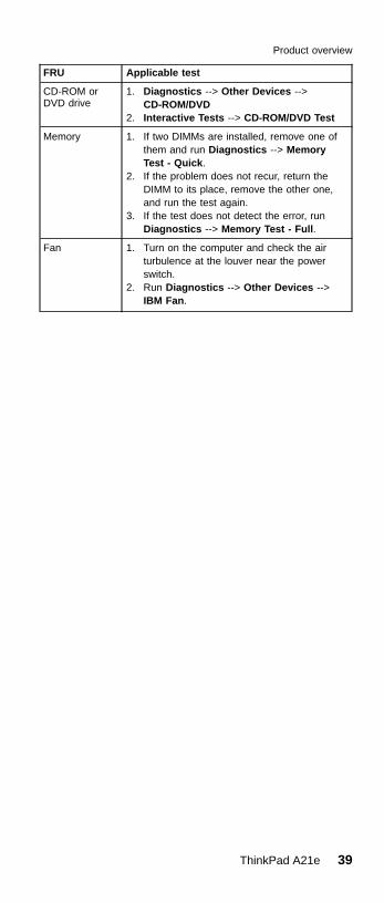
FRU Applicable test
CD-ROM orDVD drive
1. Diagnostics --> Other Devices -->CD-ROM/DVD
2. Interactive Tests --> CD-ROM/DVD Test
Memory 1. If two DIMMs are installed, remove one ofthem and run Diagnostics --> MemoryTest - Quick.
2. If the problem does not recur, return theDIMM to its place, remove the other one,and run the test again.
3. If the test does not detect the error, runDiagnostics --> Memory Test - Full.
Fan 1. Turn on the computer and check the airturbulence at the louver near the powerswitch.
2. Run Diagnostics --> Other Devices -->IBM Fan.
Product overview
ThinkPad A21e 39
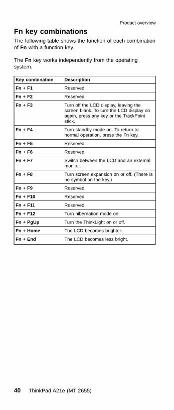
Fn key combinationsThe following table shows the function of each combinationof Fn with a function key.
The Fn key works independently from the operatingsystem.
Key combination Description
Fn + F1 Reserved.
Fn + F2 Reserved.
Fn + F3 Turn off the LCD display, leaving thescreen blank. To turn the LCD display onagain, press any key or the TrackPointstick.
Fn + F4 Turn standby mode on. To return tonormal operation, press the Fn key.
Fn + F5 Reserved.
Fn + F6 Reserved.
Fn + F7 Switch between the LCD and an externalmonitor.
Fn + F8 Turn screen expansion on or off. (There isno symbol on the key.)
Fn + F9 Reserved.
Fn + F10 Reserved.
Fn + F11 Reserved.
Fn + F12 Turn hibernation mode on.
Fn + PgUp Turn the ThinkLight on or off.
Fn + Home The LCD becomes brighter.
Fn + End The LCD becomes less bright.
Product overview
40 ThinkPad A21e (MT 2655)

Symptom-to-FRU index
The symptom-to-FRU index in this section lists symptomsand errors and their possible causes. The most likelycause is listed first, in boldface type.
Note: Do the FRU replacement or other actions in thesequence shown in the column headed “FRU oraction, in sequence.” If replacing a FRU does notsolve the problem, put the original part back in thecomputer. Do not replace a nondefective FRU.
This index can also help you determine, during regularservicing, what FRUs are likely to need to be replacednext.
A numeric error is displayed for each error detected inPOST or system operation. In the displays, n can be anynumber.
If no numeric code is displayed, check the narrativedescriptions of symptoms. If the symptom is not describedthere, go to “Intermittent problems” on page 46.
NoteFor an IBM device not supported by diagnosticcodes in the ThinkPad notebook computers, see themanual for that device.
Numeric error codes
Symptom or error FRU or action, in sequence
0175Bad CRC1, stop POST task —The EEPROM checksum is notcorrect.
System board.
0187EAIA data access error — Theaccess to EEPROM has failed.
System board.
0188Invalid RFID serializationinformation area or bad CRC2— The EEPROM checksum isnot correct.
System board.
0189Invalid RFID configurationinformation area — TheEEPROM checksum is notcorrect.
System board.
(continued)
Symptom-to-FRU index
ThinkPad A21e 41

Symptom or error FRU or action, in sequence
0190Critical low battery error.
1. Charge the battery pack.2. Battery pack.
0200Hard disk error — The harddisk is not working.
1. Reseat the hard-diskdrive.
2. Load Setup Defaults in IBMBIOS Setup Utility.
3. Hard-disk drive.4. System board.
021xStuck key — Keyboard error.
Run interactive tests of thekeyboard and the auxiliaryinput device.
0220Monitor type error — Monitortype does not match the onespecified in CMOS.
Load Setup Defaults in IBMBIOS Setup Utility.
0230Shadow RAM error — Theshadow RAM failure at offsetnnnn.
System board.
0231System RAM failure at offsetnnnn.
1. DIMM.2. System board.
0232Extended RAM error —Extended RAM failure at offsetnnnn.
1. DIMM.2. System board.
0250System battery error — Systembattery is dead.
Replace the backup batteryand run IBM BIOS SetupUtility to reset the time anddate.
0251System CMOS checksumbad—Default configurationused.
Replace the backup batteryand run IBM BIOS SetupUtility to reset the time anddate.
0252Password checksum bad —The password is cleared.
Reset the password byrunning IBM BIOS SetupUtility.
0260System timer error.
1. Replace the backupbattery and run IBM BIOSSetup Utility to reset thetime and date.
2. System board.
0270Real-time clock error.
1. Replace the backupbattery and run IBM BIOSSetup Utility to reset thetime and date.
2. System board.
0271Date and time error — Neitherthe date nor the time is set inthe computer.
Run IBM BIOS Setup Utility toreset the time and date.
(continued)
Symptom-to-FRU index
42 ThinkPad A21e (MT 2655)

Symptom or error FRU or action, in sequence
0280Previous boot incomplete —Default configuration used.
1. Load Setup Defaults inIBM BIOS Setup Utility.
2. DIMM.3. System board.
02D0System cache error.
02B2Incorrect drive A type.
1. Diskette drive.2. External FDD cable.3. I/O card.
02F4EISA CMOS not writable.
1. Load Setup Defaults inIBM BIOS Setup Utility.
2. Replace the backup battery.3. System board.
02F5DIMM test failure.
1. DIMM.2. System board.
02F6Software NMI failure.
1. DIMM.2. System board.
02F7Fail-safe timer NMI failure.
1. DIMM.2. System board.
1801Attached docking station is notsupported.
Shut down the computer andremove it from the dockingstation
Symptom-to-FRU index
ThinkPad A21e 43
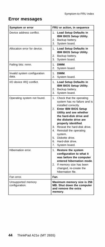
Error messages
Symptom or error FRU or action, in sequence
Device address conflict. 1. Load Setup Defaults inIBM BIOS Setup Utility.
2. Backup battery.3. System board.
Allocation error for device. 1. Load Setup Defaults inIBM BIOS Setup Utility.
2. Backup battery.3. System board.
Failing bits: nnnn. 1. DIMM.2. System board.
Invalid system configurationdata.
1. DIMM.2. System board.
I/O device IRQ conflict. 1. Load Setup Defaults inIBM BIOS Setup Utility.
2. Backup battery.3. System board.
Operating system not found. 1. Check that the operatingsystem has no failure and isinstalled correctly.
2. Enter IBM BIOS SetupUtility and see whetherthe hard-disk drive andthe diskette drive areproperly identified.
3. Reseat the hard-disk drive.4. Reinstall the operating
system.5. Diskette drive.6. Hard-disk drive.7. System board.
Hibernation error. 1. Restore the systemconfiguration to what itwas before the computerentered hibernation mode.
2. If memory size has beenchanged, re-create thehibernation file.
Fan error. Fan.
Unsupported memoryconfiguration.
Maximum memory size is 256MB. Shut down the computerand remove the extramemory.
Symptom-to-FRU index
44 ThinkPad A21e (MT 2655)
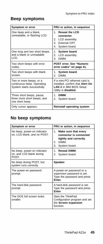
Beep symptoms
Symptom or error FRU or action, in sequence
One beep and a blank,unreadable, or flashing LCD.
1. Reseat the LCDconnector.
2. LCD assembly.3. External CRT.4. System board.
One long and two short beeps,and a blank or unreadableLCD.
1. System board.2. LCD assembly.3. DIMM.
Two short beeps with errorcodes.
POST error. See “Numericerror codes” on page 41.
Two short beeps with blankscreen.
1. System board.2. DIMM.
Two or more beeps, or acontinuous beep. OperatingSystem starts successfully.
If a mini-PCI ethernet card isinstalled, confirm that Alert OnLAN 2 in IBM BIOS SetupUtility is disabled.
Three short beeps, pause,three more short beeps, andone short beep.
1. DIMM.2. System board
Only cursor appears. Reinstall operating system.
No beep symptoms
Symptom or error FRU or action, in sequence
No beep, power-on indicatoron, LCD blank, and no POST.
1. Make sure that everyconnector is connectedtightly and correctly.
2. DIMM.3. System board.
No beep, power-on indicatoron, and LCD blank duringPOST.
1. Reseat DIMM.2. System board.
No beep during POST, butsystem runs correctly.
Speaker.
The power-on passwordprompt.
A power-on password or asupervisor password is set.Type the password and pressEnter.
The hard-disk passwordprompt.
A hard-disk password is set.Type the password and pressEnter.
The DOS full screen lookssmaller.
Start the ThinkPadConfiguration program and setthe Screen expansionfunction.
Symptom-to-FRU index
ThinkPad A21e 45

LCD-related symptoms
ImportantThe TFT LCD for the notebook computer containsmany thin-film transistors (TFTs). A small number ofdots that are missing, discolored, or always lightedis characteristic of TFT LCD technology, butexcessive pixel problems can cause viewingconcerns. The LCD should be replaced if thenumber of missing, discolored, or lighted dots in anybackground is:v XGA: 8 or more bright dots, 8 or more dark dots,
or a total of 9 or more bright and dark dots.v SVGA: 5 or more bright dots, 5 or more dark
dots, or a total of 9 or more bright and dark dots.
Note: Bright dots means pixel is always on (whiteor color.) Dark dots means pixel is walwaysoff (black color.)
Symptom or error FRU or action, in sequence
No beep, power-on indicatoron, and a blank LCD duringPOST.
System board.
v LCD backlight not working.v LCD too dark.v LCD brightness cannot be
adjusted.v LCD contrast cannot be
adjusted.
1. Reseat the LCDconnectors.
2. LCD assembly.3. System board.
v LCD screen unreadable.v Characters missing pixels.v Screen abnormal.v Wrong color displayed.
1. See important note for“LCD-related symptoms”.
2. Reseat all LCD connectors.3. LCD assembly.4. System board.
Horizontal or vertical linesdisplayed on LCD.
LCD assembly.
Intermittent problemsIntermittent system hang problems can be due to a varietyof causes that have nothing to do with a hardware defect,such as cosmic radiation, electrostatic discharge, orsoftware errors. FRU replacement should be consideredonly when a problem recurs.
When analyzing an intermittent problem, do the following:1. Run the diagnostic test for the system board in loop
mode at least 10 times.2. If no error is detected, do not replace any FRUs.
Symptom-to-FRU index
46 ThinkPad A21e (MT 2655)

3. If any error is detected, replace the FRU shown by theFRU code. Rerun the test to verify that no more errorsexist.
Undetermined problemsYou are here because the diagnostic tests did not identifywhich adapter or device failed, wrong devices are installed,a short circuit is suspected, or the system is inoperative.Follow these procedures to isolate the failing FRU (do notisolate FRUs that have no defects).
Verify that all attached devices are supported by thecomputer.
Verify that the power supply being used at the time of thefailure is operating correctly. (See “Power systemcheckout” on page 29.)1. Power off the computer.2. Visually check each FRU for damage. Replace any
damaged FRU.3. Remove or disconnect all of the following devices:
a. Non-IBM devicesb. Devices attached to the port replicatorc. Printer, mouse, and other external devicesd. Battery packe. Hard-disk drivef. External diskette driveg. DIMMh. CD-ROM and diskette drive in the Ultrabay 2000i. PC Cards
4. Power on the computer.5. Determine whether the problem has changed.6. If the problem does not recur, reconnect the removed
devices one at a time until you find the failing FRU.7. If the problem remains, replace the following FRUs one
at a time (do not replace a nondefective FRU):a. System boardb. LCD assembly
FRU replacement notices
This section contains notices related to removing andreplacing parts. Read this section carefully before replacingany FRU.
Screw noticesLoose screws can cause a reliability problem. An IBMThinkPad computer addresses this problem with specialnylon-coated screws that have the following characteristics:v They maintain tight connections.v They do not easily come loose, even with shock or
vibration.
Symptom-to-FRU index
ThinkPad A21e 47
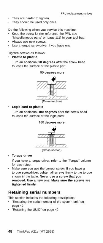
v They are harder to tighten.v They should be used only once.
Do the following when you service this machine:v Keep the screw kit (for reference the P/N, see
“Miscellaneous parts” on page 111) in your tool bag.v Always use new screws.v Use a torque screwdriver if you have one.
Tighten screws as follows:v Plastic to plastic
Turn an additional 90 degrees after the screw headtouches the surface of the plastic part:
v Logic card to plastic
Turn an additional 180 degrees after the screw headtouches the surface of the logic card:
v Torque driver
If you have a torque driver, refer to the “Torque” columnfor each step.
v Make sure you use the correct screw. If you have atorque screwdriver, tighten all screws firmly to the torqueshown in the table. Never use a screw that youremoved. Use a new one. Make sure the screws aretightened firmly.
Retaining serial numbersThis section includes the following descriptions:v “Restoring the serial number of the system unit” on
page 49v “Retaining the UUID” on page 49
FRU replacement notices
48 ThinkPad A21e (MT 2655)

Restoring the serial number of the systemunitWhen the computer was manufactured, the EEPROM onthe system board was loaded with the serial numbers ofthe system and all major components. These numbersneed to remain the same throughout the life of thecomputer.
If you replace the system board, you must restore theserial number of the system unit to its original value.
Before replacing the system board, save the original serialnumber by doing the following:1. Install the ThinkPad hardware maintenance diskette
version 1.61, and restart the computer.2. From the main menu, select 1. Set System
Identification.3. Select 2. Read S/N data from EEPROM.
The serial number for each device is displayed. Writedown the serial number of the system unit, designated asfollows:
20: System unit serial number
After you have replaced the system board, restore theserial number by doing the following:1. Install the ThinkPad hardware maintenance diskette
version 1.61 and restart the computer.2. From the main menu, select 1. Set System
Identification.3. Select 1. Add S/N data from EEPROM.
Follow the instructions on the screen.
Note: The serial number of the system unit is written onthe label attached on the bottom of the computer.
Retaining the UUIDThe Universally Unique Identifier (UUID) is a 128-bitnumber uniquely assigned to your computer at productionand stored in the EEPROM of your system board. Thealgorithm that generates the number is designed to provideunique IDs until the year A.D. 3400. No two computers inthe world have the same number.
When you replace the system board, you must set theUUID on the new system board as follows:1. Install the ThinkPad hardware maintenance diskette
version 1.61, and restart the computer.2. From the main menu, select 4. Assign UUID.
A new UUID is created and written. If a valid UUIDalready exists, it is not overwritten.
FRU replacement notices
ThinkPad A21e 49

Removing and replacing a FRU
This section presents information and drawings for use inremoving and replacing a FRU. Be sure to observe thefollowing general rules:1. Do not try to service the computer unless you have
been trained and certified. An untrained person runsthe risk of damaging parts.
2. Before replacing any FRU, review “FRU replacementnotices” on page 47.
3. Begin by removing any FRUs that have to be removedbefore the failing FRU. Any such FRUs are listed at thetop of the page. Remove them in the order in whichthey are listed.
4. Follow the correct sequence in the steps for removingthe FRU, as indicated in the drawings by the numbersin square callouts.
5. When turning a screw to replace a FRU, turn it in thedirection indicated by the arrow in the drawing.
6. When removing the FRU, move it in the directionindicated by the arrow in the drawing.
7. To put the new FRU in place, reverse the removalprocedure and follow any notes that pertain toreplacement. For information about connecting andarranging internal cables, see “Locations” on page 101.
8. When replacing a FRU, use the correct screw asshown in the procedures.
CAUTION:Before removing any FRU, power off the computer,unplug all power cords from electrical outlets, removethe battery pack, and then disconnect anyinterconnecting cables.
CAUTION:Do not disassemble the battery pack, throw it into fireor water, or short-circuit it. Dispose of the battery packas required by local ordinances or regulations.
Attention: Before the computer is powered on after FRUreplacement, make sure all screws, springs, and othersmall parts are in place and are not loose inside thecomputer. Verify this by shaking the computer gently andlistening for rattling sounds. Metallic parts or metal flakescan cause electrical short circuits.
Attention: The system board is sensitive to, and can bedamaged by, electrostatic discharge. Establish personalgrounding by touching a ground point with one hand beforetouching these units.
You must use an electrostatic discharge (ESD) strap (P/N6405959) to establish personal grounding.
Removing and replacing a FRU
50 ThinkPad A21e (MT 2655)
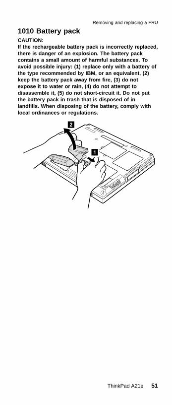
1010 Battery packCAUTION:If the rechargeable battery pack is incorrectly replaced,there is danger of an explosion. The battery packcontains a small amount of harmful substances. Toavoid possible injury: (1) replace only with a battery ofthe type recommended by IBM, or an equivalent, (2)keep the battery pack away from fire, (3) do notexpose it to water or rain, (4) do not attempt todisassemble it, (5) do not short-circuit it. Do not putthe battery pack in trash that is disposed of inlandfills. When disposing of the battery, comply withlocal ordinances or regulations.
Removing and replacing a FRU
ThinkPad A21e 51

1020 Backup batteryCAUTION:There is a danger of an explosion if the backup batteryis incorrectly replaced. The lithium battery (IBM P/N02K6572 UL-recognized component [file no. MH12210])contains lithium and can explode if it is not properlyhandled or disposed of. Replace only with a battery ofthe same type. To avoid possible injury or death, donot: (1) throw or immerse the battery into water, (2)allow it to heat to more than 100°C (212°F), or (3)attempt to repair or disassemble it. Dispose of it asrequired by local ordinances or regulations.
Step Screw (quantity) Torque
�1� M2.5 × 3.5 mm, nylon-coated (1) 39.2 Ncm(4 kgfcm)
v Battery pack (1010)
Removing and replacing a FRU
52 ThinkPad A21e (MT 2655)

Cable routing: When replacing the cable, route it as inthis drawing:
Removing and replacing a FRU
ThinkPad A21e 53

1030 Hard-disk drive
AttentionDo not drop or apply any shock to the hard-diskdrive. The hard-disk drive is sensitive to physicalshock. Incorrect handling can cause damage andpermanent loss of data.
Before removing the drive, have the user make abackup copy of all the information on the drive ifpossible.
Never remove the drive while the system isoperating or is in suspend mode.
Note: The hard disk is attached to the cover.
Step Screw (quantity)
�1� Coin screw (1) or security screw (1)
Note: Use a 2.5-mm allen wrench to remove the security screw.
(continued)
v Battery pack (1010)
Removing and replacing a FRU
54 ThinkPad A21e (MT 2655)

When removing the hard-disk drive, open the LCD a littleas shown in the figure.
When installing: Make sure that the HDD connector isfirmly connected.
Removing and replacing a FRU
ThinkPad A21e 55

1040 DIMM
Note: Loosen the screw �1�, but do not remove it.
v Battery pack (1010)
Removing and replacing a FRU
56 ThinkPad A21e (MT 2655)

1050 Mini PCI adapter
Note: Loosen the screw �1�, but do not remove it.
(continued)
v Battery pack (1010)
Removing and replacing a FRU
ThinkPad A21e 57

Note: The following two illustrations show the combo card.Connector (A) is for the LAN feature and (B) is forthe modem feature. Disconnect either (A) or (B) instep �6�. This slot also supports a Mini PCI modemcard or Mini PCI network card.
Removing and replacing a FRU
58 ThinkPad A21e (MT 2655)

Note for re-installing the Mini PCI adapter
Make sure not to pinch the connector cable (A) under theMini PCI adapter. Place the cable (A) as shown in thefollowing figure.
Removing and replacing a FRU
ThinkPad A21e 59

1060 Ultrabay 2000 deviceAny of several devices can be inserted into the Ultrabay2000. The procedure for installing and removing is thesame for every device.
Note: When you release the switch in step �1� the leverpops out. Pull the lever a little in step �2� to releasethe device from the bay.
Removing and replacing a FRU
60 ThinkPad A21e (MT 2655)
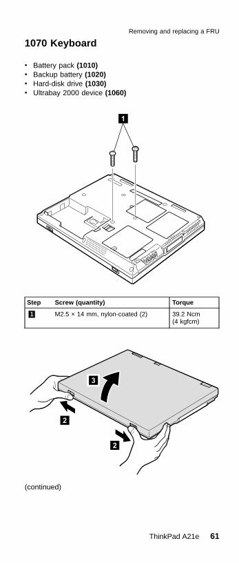
1070 Keyboard
Step Screw (quantity) Torque
�1� M2.5 × 14 mm, nylon-coated (2) 39.2 Ncm(4 kgfcm)
(continued)
v Battery pack (1010)v Backup battery (1020)v Hard-disk drive (1030)v Ultrabay 2000 device (1060)
Removing and replacing a FRU
ThinkPad A21e 61

Removing and replacing a FRU
62 ThinkPad A21e (MT 2655)

When installing the easy-button cover, do as follows:
Removing and replacing a FRU
ThinkPad A21e 63

When installing: When installing the keyboard, do asfollows:
1. Install the new keyboard, following the directions in thefigure. Make sure that the keyboard edges, shown inthe figure as (A), (B), and (C), are under the frame.
2. Insert your fingers into the PC Card slot on the left ofthe computer and the Ultrabay 2000 slot on the right ofthe computer as shown in �1�. Then, with your fingersin those slots as in �2�, latch the keyboard in place byusing your thumbs to press firmly on the Shift keys.Press the Y key to connect the keyboard to theconnector on the under side of the key �3�.
3. To make sure that the front side of the keyboard ishoused firmly, gently press the Shift keys with your
Removing and replacing a FRU
64 ThinkPad A21e (MT 2655)

thumbs and try to slide the keyboard towards you. Donot push parts (A) and (B) on the keyboard strongly; todo so might cause distortion of the Ultrabay 2000 slotand the PC Card slot.
4. After the fastening of two screws of bottom side, pushthe Y key again to connect the keyboard firmly to theconnector on the underside of the key.
Removing and replacing a FRU
ThinkPad A21e 65

1080 Keyboard CRU insulator
v Battery pack (1010)v Backup battery (1020)v Hard-disk drive (1030)v Ultrabay 2000 device (1060)v Keyboard (1070)
Removing and replacing a FRU
66 ThinkPad A21e (MT 2655)
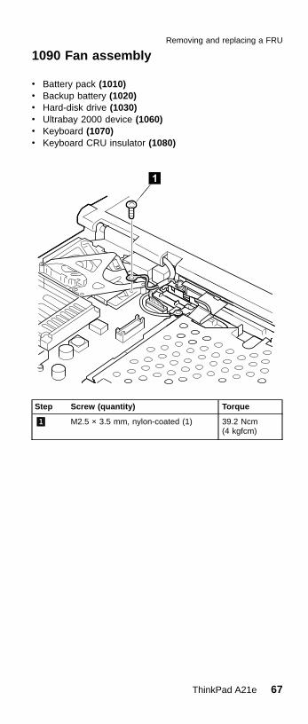
1090 Fan assembly
Step Screw (quantity) Torque
�1� M2.5 × 3.5 mm, nylon-coated (1) 39.2 Ncm(4 kgfcm)
v Battery pack (1010)v Backup battery (1020)v Hard-disk drive (1030)v Ultrabay 2000 device (1060)v Keyboard (1070)v Keyboard CRU insulator (1080)
Removing and replacing a FRU
ThinkPad A21e 67

Step Screw (quantity) Torque
�2� M2.0 × 13.5 mm, nylon-coated (4) 24.5 Ncm(2.5 kgfcm)
Removing and replacing a FRU
68 ThinkPad A21e (MT 2655)
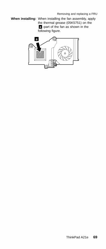
When installing: When installing the fan assembly, applythe thermal grease (05K5751) on the�a�-part of the fan as shown in thefollowing figure.
Removing and replacing a FRU
ThinkPad A21e 69
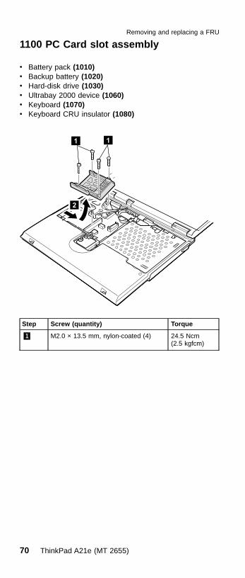
1100 PC Card slot assembly
Step Screw (quantity) Torque
�1� M2.0 × 13.5 mm, nylon-coated (4) 24.5 Ncm(2.5 kgfcm)
v Battery pack (1010)v Backup battery (1020)v Hard-disk drive (1030)v Ultrabay 2000 device (1060)v Keyboard (1070)v Keyboard CRU insulator (1080)
Removing and replacing a FRU
70 ThinkPad A21e (MT 2655)

When installing the PC card slot assembly, do as shown inthe figure.
Removing and replacing a FRU
ThinkPad A21e 71

1110 Hinge cover
Step Screw (quantity) Torque
�1� M2.5 × 14 mm, nylon-coated (3) 39.2 Ncm(4 kgfcm)
(continued)
v Battery pack (1010)v Backup battery (1020)v Hard-disk drive (1030)v Ultrabay 2000 device (1060)v Keyboard (1070)v Keyboard CRU insulator (1080)
Removing and replacing a FRU
72 ThinkPad A21e (MT 2655)
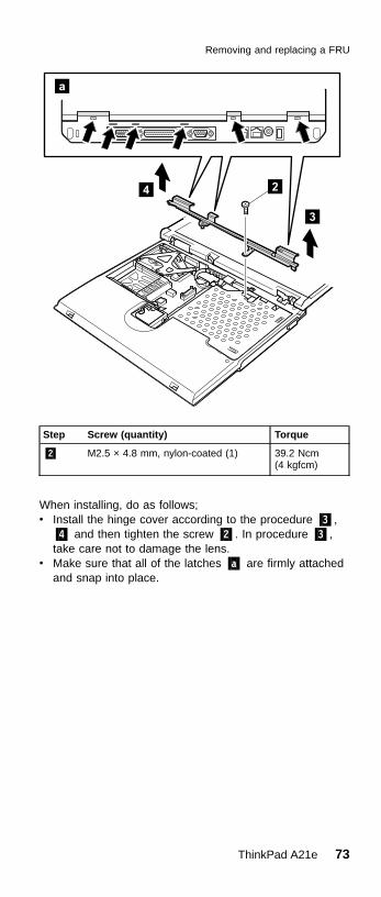
Step Screw (quantity) Torque
�2� M2.5 × 4.8 mm, nylon-coated (1) 39.2 Ncm(4 kgfcm)
When installing, do as follows;v Install the hinge cover according to the procedure �3�,
�4� and then tighten the screw �2�. In procedure �3�,take care not to damage the lens.
v Make sure that all of the latches �a� are firmly attachedand snap into place.
Removing and replacing a FRU
ThinkPad A21e 73

1120 Keyboard bezel
Step Screw (quantity) Torque
�1� M2.5 × 3.5 mm, nylon-coated (3) 39.2 Ncm(4 kgfcm)
(continued)
v Battery pack (1010)v Backup battery (1020)v Hard-disk drive (1030)v Ultrabay 2000 device (1060)v Keyboard (1070)v Keyboard CRU insulator (1080)v Hinge cover (1110)
Removing and replacing a FRU
74 ThinkPad A21e (MT 2655)

Step Screw (quantity) Torque
�2� M2.5 × 14 mm, nylon-coated (1) 39.2 Ncm(4 kgfcm)
�3� M2.5 × 4.8 mm, nylon-coated (2) 39.2 Ncm(4 kgfcm)
Removing and replacing a FRU
ThinkPad A21e 75
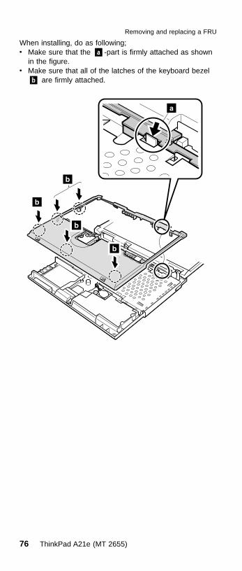
When installing, do as following;v Make sure that the �a�-part is firmly attached as shown
in the figure.v Make sure that all of the latches of the keyboard bezel
�b� are firmly attached.
Removing and replacing a FRU
76 ThinkPad A21e (MT 2655)

1130 Speaker
Step Screw (quantity) Torque
�1� M2.5 × 14 mm, nylon-coated (2) 39.2 Ncm(4 kgfcm)
v Battery pack (1010)v Backup battery (1020)v Hard-disk drive (1030)v Ultrabay 2000 device (1060)v Keyboard (1070)v Keyboard CRU insulator (1080)v Hinge cover (1110)v Keyboard bezel (1120)
Removing and replacing a FRU
ThinkPad A21e 77

1140 Hard-disk bay
Step Screw (quantity) Torque
�1� M2.5 × 4.8 mm, nylon-coated (1) 39.2 Ncm(4 kgfcm)
v Battery pack (1010)v Backup battery (1020)v Hard-disk drive (1030)v Ultrabay 2000 device (1060)v Keyboard (1070)v Keyboard CRU insulator (1080)v Hinge cover (1110)v Keyboard bezel (1120)v Speaker (1130)
Removing and replacing a FRU
78 ThinkPad A21e (MT 2655)

When installing: Make sure that the �a�-parts of theinsulation are not came off and the�b�-part is not turned over.
Removing and replacing a FRU
ThinkPad A21e 79

1150 Ultrabay 2000 slot
Step Screw (quantity) Torque
�1� M2.5 × 14 mm, nylon-coated (1) 39.2 Ncm(4 kgfcm)
(continued)
v Battery pack (1010)v Backup battery (1020)v Hard-disk drive (1030)v Ultrabay 2000 device (1060)v Keyboard (1070)v Keyboard CRU insulator (1080)v Hinge cover (1110)v Keyboard bezel (1120)
Removing and replacing a FRU
80 ThinkPad A21e (MT 2655)
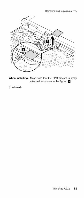
When installing: Make sure that the FPC bracket is firmlyattached as shown in the figure �a�.
(continued)
Removing and replacing a FRU
ThinkPad A21e 81

Step Screw (quantity) Torque
�3� M2.5 × 4.8 mm, nylon-coated (1) 39.2 Ncm(4 kgfcm)
Step Screw (quantity) Torque
�4� M2 × 13.5 mm, nylon-coated (2) 24.5 Ncm(2.5 kgfcm)
�5� M2.5 × 4.8 mm, nylon-coated (2) 39.2 Ncm(4 kgfcm)
Removing and replacing a FRU
82 ThinkPad A21e (MT 2655)

When installing: Make sure that the guide of the slot isfirmly attached �1�and if the eject leverhas been poped out, push it back in thedirection of arrow �2� until it snaps, andthen push the upper-right corner of theslot �3� to fix it firmly.
Removing and replacing a FRU
ThinkPad A21e 83

1160 System board
Step Screw (quantity) Torque
�4� M2.5 × 4.8 mm, nylon-coated (1) 39.2 Ncm(4 kgfcm)
v Battery pack (1010)v Backup battery (1020)v Hard-disk drive (1030)v DIMM (1040)v Mini PCI adapter (1050)v Ultrabay 2000 device (1060)v Keyboard (1070)v Keyboard CRU insulator (1080)v Fan assembly (1090)v PC card slot assembly (1100)v Hinge cover (1110)v Keyboard bezel (1120)v Speaker (1130)v Hard-disk bay(1140)v Ultrabay 2000 slot (1150)
Removing and replacing a FRU
84 ThinkPad A21e (MT 2655)

When installing: Make sure that all of the guide are firmlyattached �1� and you fasten theconnector firmly to the underside of thesystem board �2�.
Removing and replacing a FRU
ThinkPad A21e 85
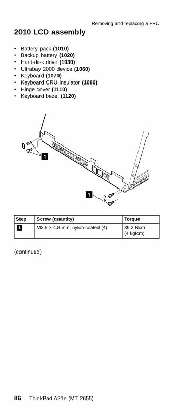
2010 LCD assembly
Step Screw (quantity) Torque
�1� M2.5 × 4.8 mm, nylon-coated (4) 39.2 Ncm(4 kgfcm)
(continued)
v Battery pack (1010)v Backup battery (1020)v Hard-disk drive (1030)v Ultrabay 2000 device (1060)v Keyboard (1070)v Keyboard CRU insulator (1080)v Hinge cover (1110)v Keyboard bezel (1120)
Removing and replacing a FRU
86 ThinkPad A21e (MT 2655)

Step Screw (quantity) Torque
�2� M2.5 × 4.8 mm, nylon-coated (1) 39.2 Ncm(4 kgfcm)
Step Screw (quantity) Torque
�3� M2.5 × 3.5 mm, nylon-coated (1) 39.2 Ncm(4 kgfcm)
�4� M2.5 × 14 mm, nylon-coated (1) 39.2 Ncm(4 kgfcm)
(continued)
Removing and replacing a FRU
ThinkPad A21e 87

Pull the bandle of LCD cable out from the cable guide ofthe LCD assembly in the direction of the arrow �5� asshown in the following figure.
Pull the LCD cable connector up in the direction of thearrow �6� as shown in the following figure.
When installing: Make sure that the LCD cable connectoris firmly attached and then tighten thescrews of each terminals.
(continued)
Removing and replacing a FRU
88 ThinkPad A21e (MT 2655)

Step Screw (quantity) Torque
�7� M2.5 × 4.8 mm, nylon-coated (2) 39.2 Ncm(4 kgfcm)
Removing and replacing a FRU
ThinkPad A21e 89

2020 Front bezel
12.1-in. LCD
Step Screw (quantity) Torque
�1� M2.5 × 4.8 mm, nylon-coated (3) 39.2 Ncm(4 kgfcm)
v Battery pack (1010)v Backup battery (1020)v Hard-disk drive (1030)v Ultrabay 2000 device (1060)v Keyboard (1070)v Keyboard CRU insulator (1080)v Hinge cover (1110)v Keyboard bezel (1120)v LCD assembly (2010)
Removing and replacing a FRU
90 ThinkPad A21e (MT 2655)

13.3-in. and 14.1-in. LCD
Step Screw (quantity) Torque
�1� M2.5 × 4.8 mm, nylon-coated (3) 39.2 Ncm(4 kgfcm)
Removing and replacing a FRU
ThinkPad A21e 91

2030 Inverter card
12.1-in. LCD
Step Screw (quantity) Torque
�1� M2.5 × 4.8 mm, nylon-coated (3) 39.2 Ncm(4 kgfcm)
v Battery pack (1010)v Backup battery (1020)v Hard-disk drive (1030)v Ultrabay 2000 device (1060)v Keyboard (1070)v Keyboard CRU insulator (1080)v Fan assembly (1090)v Hinge cover (1120)v Keyboard bezel (1130)v LCD assembly (2010)v Front bezel (2020)
Removing and replacing a FRU
92 ThinkPad A21e (MT 2655)

13.3-in. and 14.1-in. LCD
Cable routing: When replacing the inverter card, routethe connector cable as in the followingfigure:
Removing and replacing a FRU
ThinkPad A21e 93

2040 LCD panel
12.1-in. LCD
Step Screw (quantity) Torque
�1� M2.5 × 4.8 mm, nylon-coated (5) 39.2 Ncm(4 kgfcm)
(continued)
v Battery pack (1010)v Backup battery (1020)v Hard-disk drive (1030)v Ultrabay 2000 device (1060)v Keyboard (1070)v Keyboard CRU insulator (1080)v Fan assembly (1090)v Hinge cover (1120)v Keyboard bezel (1130)v LCD assembly (2010)v Front bezel (2020)
Removing and replacing a FRU
94 ThinkPad A21e (MT 2655)

Removing and replacing a FRU
ThinkPad A21e 95
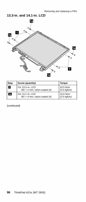
13.3-in. and 14.1-in. LCD
Step Screw (quantity) Torque
�1� For 13.3–in. LCDM2 × 4 mm, nylon-coated (4)
24.5 Ncm(2.5 kgfcm)
�1a� For 14.1–in. LCDM2 × 4 mm, nylon-coated (4)
24.5 Ncm(2.5 kgfcm)
(continued)
Removing and replacing a FRU
96 ThinkPad A21e (MT 2655)

Step Screw (quantity) Torque
�2� M2.5 × 4.8 mm, nylon-coated (1) 39.2 Ncm(4 kgfcm)
Removing and replacing a FRU
ThinkPad A21e 97

Cable routing: When installing the LCD, route theconnector cable as in the following figure:
Removing and replacing a FRU
98 ThinkPad A21e (MT 2655)

2050 Sub card
Step Screw (quantity) Torque
�2� Hex stud (6) 39.2 Ncm(4 kgfcm)
�3� M2.5 × 4.8 mm, nylon-coated (4) 39.2 Ncm(4 kgfcm)
v Battery pack (1010)v Backup battery (1020)v Hard-disk drive (1030)v DIMM (1040)v Mini PCI adapter (1050)v Ultrabay 2000 device (1060)v Keyboard (1070)v Keyboard CRU insulator (1080)v Fan assembly (1090)v PC card slot assembly (1100)v Hinge cover (1110)v Keyboard bezel (1120)v Speaker (1130)v Hard-disk bay(1140)v Ultrabay 2000 slot (1150)v System board (1160)v LCD assembly (2010)
Removing and replacing a FRU
ThinkPad A21e 99
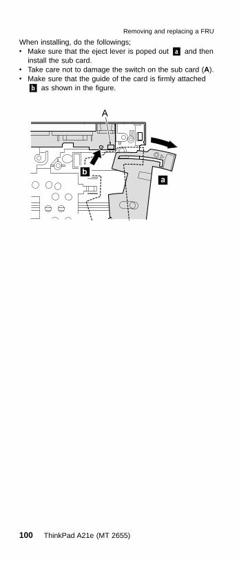
When installing, do the followings;v Make sure that the eject lever is poped out �a� and then
install the sub card.v Take care not to damage the switch on the sub card (A).v Make sure that the guide of the card is firmly attached
�b� as shown in the figure.
A
Removing and replacing a FRU
100 ThinkPad A21e (MT 2655)

Locations
Front view�1� System status indicators�2� Power switch�3� Battery, standby mode, and UltraBay status
indicators�4� Bay latch�5� Eject button�6� Ultrabay 2000 device
Note: The Ultrabay 2000 accepts storagedevices, such as a DVD drive or aCD-ROM drive.
�7� TrackPoint buttons�8� TrackPoint pointing stick�9� ThinkPad button�10� Volume and mute buttons
Locations
ThinkPad A21e 101

Rear view�1� Security keyhole�2� Serial connector�3� Parallel connector�4� External-monitor connector�5� Modem connector�6� Ethernet connector�7� Power jack�8� Universal serial bus (USB) connector
Locations
102 ThinkPad A21e (MT 2655)

Bottom view�1� Built-in monaural speaker�2� Battery pack�3� Battery pack latches�4� Docking connector�5� Mini PCI card slot�6� DIMM slot�7� PC card slots�8� PC card eject button�9� Stereo headphone jack�10� Stereo line-in jack�11� Microphone jack�12� Hard-disk drive�13� LCD latches
Locations
ThinkPad A21e 103

Parts list
Overall
Parts list
104 ThinkPad A21e (MT 2655)

v Each FRU is available for all types/models, unlessspecific types or models are given.
v The FRUs marked with asterisk are CRU (customerreplacable unit).
No. FRU P/N
a - f See “Miscellaneous parts” on page 111.
1 LCD unit (see “LCD FRUs” on page 107)
2 Keyboard bezel assembly 08K7133
3 Fan assembly 08K7128
4 PC Card slots 08K7127
5 I/O card assembly 08K3364
6 Base cover assembly 08K7123
for IIPC (2655-xxA) 26P9168
7 Ultrabay 2000 CD-ROM drive* (see “Optional FRUs” onpage 113.)
for optional Ultrabay 2000 device, see “Optional FRUs” onpage 113.
8 Cover, Mini PCI adapter slot* 08K7137
9 Battery pack (NiMH)* (see “Optional FRUs” on page 113.)
for optional battery pack (Li-Ion), see “Optional FRUs” onpage 113.
10 Backup battery 02K6572
11 Cover, DIMM slot* 08K7136
12 Speaker assembly 08K7135
13 64-MB SDRAM SO DIMM* (see “Optional FRUs” onpage 113.)
for optional 128-MB SDRAM SO DIMM, see “OptionalFRUs” on page 113.
14 Mini PCI modem card* (see “Optional FRUs” on page 113.)
Mini PCI combo card (see “Optional FRUs” on page 113.)
for optional Mini PCI adapter, see “Optional FRUs” onpage 113.
15 System board
with Celeron processor 650 MHz for2655-21x, 22x, 23x, 71x, 72x, 73x
08K3360
with Celeron processor 700 MHz forMT2655-31x, 32x, 33x, 41x, 42x, 43x,81x, 82x, 83x, 91x, 92x, 93x
08K3361
16 Hard-disk drive (20.0 GB)* (see “Optional FRUs” onpage 113.)
for optional hard-disk drive, see “Optional FRUs” onpage 113.
(continued)
Parts list
ThinkPad A21e 105

No. FRU P/N
17 Cover, hard-disk drive* 08K7138
18 Keyboard* (see “Keyboard” on page 110)
19 Pointing stick cap* 84G6536
— AC adapter (72W), 2-pin* (see “Optional FRUs” onpage 113.)
AC adapter (72W), 3-pin* (see “Optional FRUs” onpage 113.)
— Telephone cable* 27L0603
Parts list
106 ThinkPad A21e (MT 2655)

LCD FRUs
12.1-in. SVGA TFT
Following FRUs are available for MT2655-21x, 22x, 23x,71x, 72x, 73x.
No. FRU P/N
1 LCD cover kit 08K7130
2 Hinge 08K7132
3 LCD cable assembly, 12.1 SVGA 27L0620
4 LCD panel (SANYO) 12.1 SVGA 05K9909
LCD panel (SAMSUNG) 12.1 SVGA 05K9869
5 Inverter card 08K3417
Parts list
ThinkPad A21e 107
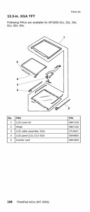
13.3-in. XGA TFT
Following FRUs are available for MT2655-31x, 32x, 33x,81x, 82x, 83x.
No. FRU P/N
1 LCD cover kit 08K7130
2 Hinge 08K7132
3 LCD cable assembly, XGA 27L0621
4 LCD panel (LG) 13.3 XGA 05K9892
5 Inverter card 08K3363
Parts list
108 ThinkPad A21e (MT 2655)

14.1-in. XGA TFT
Following FRUs are available for MT2655-41x, 42x, 43x,91x, 92x, 93x.
No. FRU P/N
1 LCD cover kit 08K7410
2 Hinge 08K7132
3 LCD cable assembly, XGA 27L0621
4 LCD panel (Hyundai) 14.1 XGA 05K9907
LCD panel (LG) 14.1 XGA 05K9905
LCD panel (SAMSUNG) 14.1 XGA 05K9906
5 Inverter card 08K3363
Parts list
ThinkPad A21e 109

Keyboard
Language P/N (NMB) P/N(ALPS)
Arabic 02K5868 02K5839
Belgian 02K5863 02K5834
Canadian French 02K5850 02K5821
Chinese, traditional 02K5865 02K5836
Czech 02K5869 02K5840
Danish 02K5856 02K5827
Dutch 02K5853 02K5824
European Spanish 02K5858 02K5829
European French 02K5852 02K5823
German 02K5851 02K5822
Greek 02K5871 02K5842
Hungarian 02K5870 02K5841
Hebrew 02K5867 02K5838
Italian 02K5857 02K5828
Japanese 02K5848 02K5819
Latin American Spanish 02K5861 02K5832
Norwegian 02K5855 02K5826
Polish 02K5873 02K5844
Portuguese 02K5860 02K5831
Russian 02K5866 02K5837
Slovakian 02K5872 02K5843
Slovenian 02K5874 02K5845
Swedish or Finnish 02K5854 02K5825
Swiss 02K5859 02K5830
Turkish 02K5864 02K5835
U.K. English 02K5849 02K5820
U.S. English 02K5847 02K5818
Parts list
110 ThinkPad A21e (MT 2655)

Miscellaneous parts
FRU P/N
Screw kit (including nylon-coated screws):v M2.5 x 14 mm, bind head (15)v M2.5 x 4.8 mm, flat head (20)v M2.5 x 3.5 mm, flat head (10)v M2.0 x 13.5 mm, pan head (15)v M2.0 x 4.0 mm, small head (10)v Hex stud D-sub (10)v Coin screw (1)v Security screw (1)v Blank cap, enhanced portv Screw caps, rearv Screw capsv Screw caps (painted)v Screw caps (not painted)
08K7139
Base miscellaneous parts:v I/O platev Spring, battery lockv Lid, docking FRv Lid, docking RRv Spring, lid dockingv Spring, lid PC cardv Lid, PC cardv Rubber footv ESD plate, audiov Insulator for base coverv Ultrabay 2000 bay eject leverv Spring, Ultrabay 2000 bay eject leverv Puller, Ultrabay 2000 bayv Label danger, backup batteryv Rubber footv Thermal spongev Knob, battery lockv Latch, battery lockv EMI plate, modemv EMI shield, battery bayv ESD plate, DIMMv ESD plate, docking connectorv ESD plate, CPUv Greasev Screw capsv Screw caps, rear
08K7125
(continued)
Parts list
ThinkPad A21e 111

FRU P/N
System miscellaneous parts:v (a) Hinge cover assemblyv (i) Easy button coverv I/O card spacerv Cable, RJ11 to system board dockingv (g) Backup battery holderv (f) Ultrabay 2000 guide railv (h) Hard-disk bay guide railv (b) Keyboard CRU insulatorv Mini PCI guidev Keyboard supportv (d) ESD plate spring CSBv (e) ESD plate CSBv (c) ESD fan coverv Greasev Screw capsv Screw caps, rear
08K7129
Miscellaneous parts, for I/O cardv DC jack connectorv Cable RJ11/45 to mini PCIv Insulator, modular jackv Insulation tapev Screw capsv Screw caps, rear
08K6683
Parts list
112 ThinkPad A21e (MT 2655)
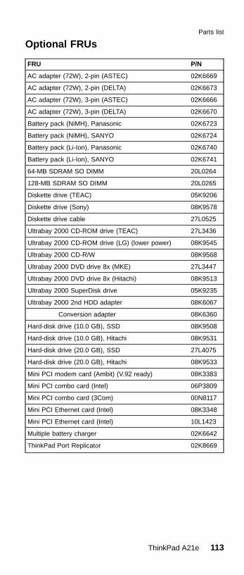
Optional FRUs
FRU P/N
AC adapter (72W), 2-pin (ASTEC) 02K6669
AC adapter (72W), 2-pin (DELTA) 02K6673
AC adapter (72W), 3-pin (ASTEC) 02K6666
AC adapter (72W), 3-pin (DELTA) 02K6670
Battery pack (NiMH), Panasonic 02K6723
Battery pack (NiMH), SANYO 02K6724
Battery pack (Li-Ion), Panasonic 02K6740
Battery pack (Li-Ion), SANYO 02K6741
64-MB SDRAM SO DIMM 20L0264
128-MB SDRAM SO DIMM 20L0265
Diskette drive (TEAC) 05K9206
Diskette drive (Sony) 08K9578
Diskette drive cable 27L0525
Ultrabay 2000 CD-ROM drive (TEAC) 27L3436
Ultrabay 2000 CD-ROM drive (LG) (lower power) 08K9545
Ultrabay 2000 CD-R/W 08K9568
Ultrabay 2000 DVD drive 8x (MKE) 27L3447
Ultrabay 2000 DVD drive 8x (Hitachi) 08K9513
Ultrabay 2000 SuperDisk drive 05K9235
Ultrabay 2000 2nd HDD adapter 08K6067
Conversion adapter 08K6360
Hard-disk drive (10.0 GB), SSD 08K9508
Hard-disk drive (10.0 GB), Hitachi 08K9531
Hard-disk drive (20.0 GB), SSD 27L4075
Hard-disk drive (20.0 GB), Hitachi 08K9533
Mini PCI modem card (Ambit) (V.92 ready) 08K3383
Mini PCI combo card (Intel) 06P3809
Mini PCI combo card (3Com) 00N8117
Mini PCI Ethernet card (Intel) 08K3348
Mini PCI Ethernet card (Intel) 10L1423
Multiple battery charger 02K6642
ThinkPad Port Replicator 02K8669
Parts list
ThinkPad A21e 113

Common parts list
Tools
Triconnector wrap plug 72X8546
PC test card 35G4703
Audio wrap cable 66G5180
USB parallel test cable 05K2580
Screwdriver kit 95F3598
Torque screwdriver 05K4695
5mm socket wrench 05K4694
Screwdriver 27L8126
ThinkPad hardware maintenance diskette version1.61Note: Download the file from the Web site.
–
Power cords (system)IBM power cords for a specific country are usuallyavailable only in that region:
For 2-pin power cords:
Region P/N
Canada, United States of America 13H5264
Japan 13H5273
Argentina 36L8870
For 3-pin power cords:
Region P/N
Australia, New Zealand 76H3514
Taiwan, Thailand 76H3516
Italy 76H3530
Denmark 76H3520
UK, Hong Kong 76H3524
European countries 76H3518
India, South Africa 76H3522
Israel 76H3532
People’s Republic of China (other than HongKong)
02K0539
Switzerland 76H3528
Parts list
114 ThinkPad A21e (MT 2655)

Notices
References in this publication to IBM products, programs,or services do not imply that IBM intends to make theseavailable in all countries in which IBM operates. Anyreference to an IBM product, program, or service is notintended to state or imply that only that IBM product,program, or service may be used. Any functionallyequivalent product, program, or service that does notinfringe any of the intellectual property rights of IBM maybe used instead of the IBM product, program, or service.The evaluation and verification of operation in conjunctionwith other products, except those expressly designated byIBM, are the responsibility of the user.
IBM may have patents or pending patent applicationscovering subject matter in this document. The furnishing ofthis document does not give you any license to thesepatents. You can send license inquiries, in writing, to theIBM Director of Licensing, IBM Corporation, 500 ColumbusAvenue, Thornwood, NY 10594, U.S.A.
TrademarksThe following terms are trademarks of the IBM Corporationin the United States or other countries or both:
IBMThinkPadTrackPointUltraBayAsset ID
PC-Doctor DOS is a trademark of PC-Doctor, Inc., in theUnited States and other countries.
Microsoft, Windows, Windows NT, and the Windows logoare trademarks of Microsoft Corporation in the UnitedStates and/or other countries.
Pentium and Celeron are trademarks of Intel Corporationin the Unites States and/or other countries. (For acomplete list of Intel trademarks, seehttp://www.intel.com/trademarx.htm)
Other company, product, or service names may be thetrademarks or service marks of others.
Notices
ThinkPad A21e 115

����
Part Number: 23P0899
Printed in U.S.A.
(1P) P/N: 23P0899