Embed Size (px)
Citation preview
ibm.com/redbooks
IBM CommunicationsServer for AIX, V6New Features and Implementation Scenarios
Byron BraswellHyunKeun Park
Ascension Sanchez
Scenarios for Telnet Redirector, SSL, and Service Location Protocol
Covers SNA features Enterprise Extender, Branch Extender, MPC+
Examples of Web Admin, 64-bit apps and more


IBM Communications Server for AIX, V6New Features and Implementation Scenarios
July 2000
SG24-5947-00
International Technical Support Organization
© Copyright International Business Machines Corporation 2000. All rights reserved.Note to U.S Government Users – Documentation related to restricted rights – Use, duplication or disclosure issubject to restrictions set forth in GSA ADP Schedule Contract with IBM Corp.
First Edition (July 2000)
This edition applies to Version 6.0 of IBM Communications Server for AIX, Program Number 5765-E51for use with the AIX Operating System.
Comments may be addressed to:IBM Corporation, International Technical Support OrganizationDept. HZ8 Building 678P.O. Box 12195Research Triangle Park, NC 27709-2195
When you send information to IBM, you grant IBM a non-exclusive right to use or distribute theinformation in any way it believes appropriate without incurring any obligation to you.
Before using this information and the product it supports, be sure to read the general information inAppendix A, “Special notices” on page 225.
Take Note!
Contents
Preface . . . . . . . . . . . . . . . . . . . . . . . . . . . . . . . . . . . . . . . . . . . . . . . . . . . .ixThe team that wrote this redbook. . . . . . . . . . . . . . . . . . . . . . . . . . . . . . . . . . . . ixComments welcome. . . . . . . . . . . . . . . . . . . . . . . . . . . . . . . . . . . . . . . . . . . . . . x
Part 1. Introduction . . . . . . . . . . . . . . . . . . . . . . . . . . . . . . . . . . . . . . . . . . . . . . . . . . . . . 1
Chapter 1. Overview . . . . . . . . . . . . . . . . . . . . . . . . . . . . . . . . . . . . . . . . . 31.1 Secure Sockets Layer support . . . . . . . . . . . . . . . . . . . . . . . . . . . . . . . 31.2 TN Redirector . . . . . . . . . . . . . . . . . . . . . . . . . . . . . . . . . . . . . . . . . . . . 31.3 Service Location Protocol . . . . . . . . . . . . . . . . . . . . . . . . . . . . . . . . . . . 41.4 Enterprise Extender . . . . . . . . . . . . . . . . . . . . . . . . . . . . . . . . . . . . . . . 41.5 Branch Extender . . . . . . . . . . . . . . . . . . . . . . . . . . . . . . . . . . . . . . . . . 51.6 MPC+ support . . . . . . . . . . . . . . . . . . . . . . . . . . . . . . . . . . . . . . . . . . . 51.7 Web administration. . . . . . . . . . . . . . . . . . . . . . . . . . . . . . . . . . . . . . . . 51.8 CS/AIX licensing . . . . . . . . . . . . . . . . . . . . . . . . . . . . . . . . . . . . . . . . . 61.9 CS/AIX documentation . . . . . . . . . . . . . . . . . . . . . . . . . . . . . . . . . . . . . 61.10 64-bit application support . . . . . . . . . . . . . . . . . . . . . . . . . . . . . . . . . . 61.11 Java CPI-C API . . . . . . . . . . . . . . . . . . . . . . . . . . . . . . . . . . . . . . . . . 6
Part 2. Telnet services and enhancements . . . . . . . . . . . . . . . . . . . . . . . . . . . . . . . . . . . 7
Chapter 2. Secure Sockets Layer support . . . . . . . . . . . . . . . . . . . . . . . 92.1 Secure Sockets Layer (SSL) overview . . . . . . . . . . . . . . . . . . . . . . . . . 9
2.1.1 Symmetric-key encryption . . . . . . . . . . . . . . . . . . . . . . . . . . . . . . 92.1.2 Public-key encryption . . . . . . . . . . . . . . . . . . . . . . . . . . . . . . . . . 102.1.3 Hashing functions . . . . . . . . . . . . . . . . . . . . . . . . . . . . . . . . . . . . 10
2.2 Public-key certificates . . . . . . . . . . . . . . . . . . . . . . . . . . . . . . . . . . . . 102.3 SSL implementation in CS/AIX . . . . . . . . . . . . . . . . . . . . . . . . . . . . . . 11
2.3.1 Install SSL support for CS/AIX . . . . . . . . . . . . . . . . . . . . . . . . . . 122.3.2 Enable SSL in TN3270 server/TN Redirector . . . . . . . . . . . . . . . 122.3.3 Key Management utility . . . . . . . . . . . . . . . . . . . . . . . . . . . . . . . 152.3.4 Deciding what type of certificates to use . . . . . . . . . . . . . . . . . . . 162.3.5 Deciding what type of authentication to use . . . . . . . . . . . . . . . . 17
2.4 Scenario. . . . . . . . . . . . . . . . . . . . . . . . . . . . . . . . . . . . . . . . . . . . . . . 182.4.1 Enabling SSL for a TN3270 server . . . . . . . . . . . . . . . . . . . . . . . 182.4.2 Configuring SSL security . . . . . . . . . . . . . . . . . . . . . . . . . . . . . . 192.4.3 Bringing up certificates using Personal Communications . . . . . . 252.4.4 Setting up TN3270 connections using PCOMM . . . . . . . . . . . . . 28
© Copyright IBM Corp. 2000 iii
Chapter 3. TN Redirector . . . . . . . . . . . . . . . . . . . . . . . . . . . . . . . . . . . . 333.1 Overview . . . . . . . . . . . . . . . . . . . . . . . . . . . . . . . . . . . . . . . . . . . . . . 333.2 Implementation. . . . . . . . . . . . . . . . . . . . . . . . . . . . . . . . . . . . . . . . . . 34
3.2.1 Configuring CS/AIX TN Redirector access records . . . . . . . . . . . 353.3 Scenario. . . . . . . . . . . . . . . . . . . . . . . . . . . . . . . . . . . . . . . . . . . . . . . 393.4 TN Redirector and SSL . . . . . . . . . . . . . . . . . . . . . . . . . . . . . . . . . . . 47
Chapter 4. Service Location Protocol (SLP) . . . . . . . . . . . . . . . . . . . . . 514.1 Overview . . . . . . . . . . . . . . . . . . . . . . . . . . . . . . . . . . . . . . . . . . . . . . 51
4.1.1 Service location protocol . . . . . . . . . . . . . . . . . . . . . . . . . . . . . . 514.1.2 SLP terminology . . . . . . . . . . . . . . . . . . . . . . . . . . . . . . . . . . . . . 524.1.3 SLP load balancing. . . . . . . . . . . . . . . . . . . . . . . . . . . . . . . . . . . 544.1.4 SLP scope . . . . . . . . . . . . . . . . . . . . . . . . . . . . . . . . . . . . . . . . . 55
4.2 SLP review . . . . . . . . . . . . . . . . . . . . . . . . . . . . . . . . . . . . . . . . . . . . . 574.3 SLP support in CS/AIX . . . . . . . . . . . . . . . . . . . . . . . . . . . . . . . . . . . . 58
4.3.1 Configuring TN3270 server with SLP . . . . . . . . . . . . . . . . . . . . . 584.3.2 Monitoring SLP . . . . . . . . . . . . . . . . . . . . . . . . . . . . . . . . . . . . . . 61
4.4 Scenario. . . . . . . . . . . . . . . . . . . . . . . . . . . . . . . . . . . . . . . . . . . . . . . 624.4.1 Configuring TN3270 SLP servers . . . . . . . . . . . . . . . . . . . . . . . . 634.4.2 Configuring TN3270 SLP clients . . . . . . . . . . . . . . . . . . . . . . . . . 674.4.3 Connecting to TN3270 SLP servers . . . . . . . . . . . . . . . . . . . . . . 69
Chapter 5. TN3270 inactivity timeout . . . . . . . . . . . . . . . . . . . . . . . . . . 775.1 Overview . . . . . . . . . . . . . . . . . . . . . . . . . . . . . . . . . . . . . . . . . . . . . . 775.2 Implementation. . . . . . . . . . . . . . . . . . . . . . . . . . . . . . . . . . . . . . . . . . 78
Part 3. SNA networking . . . . . . . . . . . . . . . . . . . . . . . . . . . . . . . . . . . . . . . . . . . . . . . . . 79
Chapter 6. Enterprise Extender . . . . . . . . . . . . . . . . . . . . . . . . . . . . . . . 816.1 Overview . . . . . . . . . . . . . . . . . . . . . . . . . . . . . . . . . . . . . . . . . . . . . . 816.2 An HPR overview . . . . . . . . . . . . . . . . . . . . . . . . . . . . . . . . . . . . . . . . 82
6.2.1 Rapid Transport Protocol (RTP) . . . . . . . . . . . . . . . . . . . . . . . . . 836.3 Implementation. . . . . . . . . . . . . . . . . . . . . . . . . . . . . . . . . . . . . . . . . . 896.4 Scenario. . . . . . . . . . . . . . . . . . . . . . . . . . . . . . . . . . . . . . . . . . . . . . . 92
6.4.1 Configure the rs60003 machine . . . . . . . . . . . . . . . . . . . . . . . . . 936.4.2 Configure the rs60004 machine . . . . . . . . . . . . . . . . . . . . . . . . . 996.4.3 Activate CS/AIX resources on both nodes . . . . . . . . . . . . . . . . 1016.4.4 Configure VTAM and TCP/IP on the host . . . . . . . . . . . . . . . . . 1016.4.5 Test the connection . . . . . . . . . . . . . . . . . . . . . . . . . . . . . . . . . 104
6.5 Verifying the HPR/IP connection . . . . . . . . . . . . . . . . . . . . . . . . . . . 105
Chapter 7. Branch Extender . . . . . . . . . . . . . . . . . . . . . . . . . . . . . . . . 1157.1 Overview . . . . . . . . . . . . . . . . . . . . . . . . . . . . . . . . . . . . . . . . . . . . . 115
iv IBM Communications Server for AIX, V6: New Features and Implementation Scenarios
7.2 Topology databases . . . . . . . . . . . . . . . . . . . . . . . . . . . . . . . . . . . . . 1187.2.1 Local topology database. . . . . . . . . . . . . . . . . . . . . . . . . . . . . . 1197.2.2 Network topology database . . . . . . . . . . . . . . . . . . . . . . . . . . . 119
7.3 Supported configurations . . . . . . . . . . . . . . . . . . . . . . . . . . . . . . . . . 1207.3.1 Links. . . . . . . . . . . . . . . . . . . . . . . . . . . . . . . . . . . . . . . . . . . . . 1207.3.2 Nodes. . . . . . . . . . . . . . . . . . . . . . . . . . . . . . . . . . . . . . . . . . . . 1207.3.3 LU-LU sessions . . . . . . . . . . . . . . . . . . . . . . . . . . . . . . . . . . . . 121
7.4 Implementation. . . . . . . . . . . . . . . . . . . . . . . . . . . . . . . . . . . . . . . . . 1227.5 Scenario. . . . . . . . . . . . . . . . . . . . . . . . . . . . . . . . . . . . . . . . . . . . . . 124
7.5.1 Testing the connections . . . . . . . . . . . . . . . . . . . . . . . . . . . . . . 135
Chapter 8. MPC+ support. . . . . . . . . . . . . . . . . . . . . . . . . . . . . . . . . . . 1418.1 Hardware requirements . . . . . . . . . . . . . . . . . . . . . . . . . . . . . . . . . . 1428.2 Software requirements . . . . . . . . . . . . . . . . . . . . . . . . . . . . . . . . . . . 1428.3 MPC+ configuration . . . . . . . . . . . . . . . . . . . . . . . . . . . . . . . . . . . . . 1438.4 Our scenario . . . . . . . . . . . . . . . . . . . . . . . . . . . . . . . . . . . . . . . . . . 145
8.4.1 Install the communications adapter. . . . . . . . . . . . . . . . . . . . . . 1458.4.2 Install the SNA channel for AIX feature. . . . . . . . . . . . . . . . . . . 1468.4.3 Configure the MVS operating system . . . . . . . . . . . . . . . . . . . . 1468.4.4 Configure VTAM . . . . . . . . . . . . . . . . . . . . . . . . . . . . . . . . . . . . 1488.4.5 Configure the communications adapter. . . . . . . . . . . . . . . . . . . 1508.4.6 Configure the adapter to CS/AIX . . . . . . . . . . . . . . . . . . . . . . . 158
Chapter 9. DDDLU enhancement . . . . . . . . . . . . . . . . . . . . . . . . . . . . . 1659.1 DDDLU power-off feature . . . . . . . . . . . . . . . . . . . . . . . . . . . . . . . . . 165
Part 4. Administration . . . . . . . . . . . . . . . . . . . . . . . . . . . . . . . . . . . . . . . . . . . . . . . . . 167
Chapter 10. Web Administration program. . . . . . . . . . . . . . . . . . . . . . 16910.1 Overview . . . . . . . . . . . . . . . . . . . . . . . . . . . . . . . . . . . . . . . . . . . . 169
10.1.1 Motif administration program . . . . . . . . . . . . . . . . . . . . . . . . . 16910.1.2 SMIT administration program . . . . . . . . . . . . . . . . . . . . . . . . . 17010.1.3 Command-line administration program . . . . . . . . . . . . . . . . . . 17010.1.4 Network operator facility API . . . . . . . . . . . . . . . . . . . . . . . . . 17110.1.5 Service point command facility . . . . . . . . . . . . . . . . . . . . . . . . 17210.1.6 Web Administration program . . . . . . . . . . . . . . . . . . . . . . . . . 172
10.2 Web Administration program implementation . . . . . . . . . . . . . . . . . 17410.2.1 Supported Web servers . . . . . . . . . . . . . . . . . . . . . . . . . . . . . 17410.2.2 Configuring a Web server for Web Administration. . . . . . . . . . 17510.2.3 Invoking the Web Administration program. . . . . . . . . . . . . . . . 17510.2.4 Using the Web Administration program. . . . . . . . . . . . . . . . . . 176
10.3 Scenario . . . . . . . . . . . . . . . . . . . . . . . . . . . . . . . . . . . . . . . . . . . . . 18110.3.1 Node configuration . . . . . . . . . . . . . . . . . . . . . . . . . . . . . . . . . 181
v
10.3.2 Port configuration . . . . . . . . . . . . . . . . . . . . . . . . . . . . . . . . . . 18410.3.3 Link station configuration . . . . . . . . . . . . . . . . . . . . . . . . . . . . 18610.3.4 Administration program differences . . . . . . . . . . . . . . . . . . . . 18710.3.5 LUs configuration . . . . . . . . . . . . . . . . . . . . . . . . . . . . . . . . . . 197
Chapter 11. CS/AIX licensing. . . . . . . . . . . . . . . . . . . . . . . . . . . . . . . . 19911.1 Overview . . . . . . . . . . . . . . . . . . . . . . . . . . . . . . . . . . . . . . . . . . . . 19911.2 Server license . . . . . . . . . . . . . . . . . . . . . . . . . . . . . . . . . . . . . . . . 19911.3 User license . . . . . . . . . . . . . . . . . . . . . . . . . . . . . . . . . . . . . . . . . . 200
11.3.1 TN3270 server scenario . . . . . . . . . . . . . . . . . . . . . . . . . . . . . 20111.3.2 Telnet Redirector scenario . . . . . . . . . . . . . . . . . . . . . . . . . . . 20211.3.3 APPC/CPI-C scenario. . . . . . . . . . . . . . . . . . . . . . . . . . . . . . . 20211.3.4 SNA gateway scenario . . . . . . . . . . . . . . . . . . . . . . . . . . . . . . 20311.3.5 Local dependent LU scenario . . . . . . . . . . . . . . . . . . . . . . . . . 204
11.4 Monitoring usage of CS/AIX resources . . . . . . . . . . . . . . . . . . . . . . 205
Chapter 12. HTML and docsearch . . . . . . . . . . . . . . . . . . . . . . . . . . . . 20912.1 Setting up CS/AIX HTML documentation . . . . . . . . . . . . . . . . . . . . 209
Part 5. Application development . . . . . . . . . . . . . . . . . . . . . . . . . . . . . . . . . . . . . . . . . 211
Chapter 13. 64-bit SNA applications . . . . . . . . . . . . . . . . . . . . . . . . . . 21313.1 Requirements for 64-bit support . . . . . . . . . . . . . . . . . . . . . . . . . . . 21313.2 64-bit architecture and benefits . . . . . . . . . . . . . . . . . . . . . . . . . . . 214
13.2.1 64-bit integer computation . . . . . . . . . . . . . . . . . . . . . . . . . . . 21413.2.2 Large file support . . . . . . . . . . . . . . . . . . . . . . . . . . . . . . . . . . 21513.2.3 Large application virtual address spaces . . . . . . . . . . . . . . . . 21513.2.4 Large physical memory support . . . . . . . . . . . . . . . . . . . . . . . 216
13.3 Compatibility and interoperability . . . . . . . . . . . . . . . . . . . . . . . . . . 21713.3.1 64-bit hardware compatibility . . . . . . . . . . . . . . . . . . . . . . . . . 21713.3.2 64-bit software compatibility . . . . . . . . . . . . . . . . . . . . . . . . . . 217
13.4 CS/AIX and 64-bit applications . . . . . . . . . . . . . . . . . . . . . . . . . . . . 21813.4.1 Sample applications . . . . . . . . . . . . . . . . . . . . . . . . . . . . . . . . 218
Chapter 14. Java CPI-C . . . . . . . . . . . . . . . . . . . . . . . . . . . . . . . . . . . . 22114.1 Overview . . . . . . . . . . . . . . . . . . . . . . . . . . . . . . . . . . . . . . . . . . . . 221
Appendix A. Special notices . . . . . . . . . . . . . . . . . . . . . . . . . . . . . . . . . . 225
Appendix B. Related publications . . . . . . . . . . . . . . . . . . . . . . . . . . . . . . 229B.1 IBM Redbooks . . . . . . . . . . . . . . . . . . . . . . . . . . . . . . . . . . . . . . . . . . . . 229B.2 IBM Redbooks collections. . . . . . . . . . . . . . . . . . . . . . . . . . . . . . . . . . . . 229B.3 Other resources . . . . . . . . . . . . . . . . . . . . . . . . . . . . . . . . . . . . . . . . . . . 229B.4 Referenced Web sites. . . . . . . . . . . . . . . . . . . . . . . . . . . . . . . . . . . . . . . 230
vi IBM Communications Server for AIX, V6: New Features and Implementation Scenarios

How to get IBM Redbooks . . . . . . . . . . . . . . . . . . . . . . . . . . . . . . . . . . 231IBM Redbooks fax order form . . . . . . . . . . . . . . . . . . . . . . . . . . . . . . . . . . . . 232
Index . . . . . . . . . . . . . . . . . . . . . . . . . . . . . . . . . . . . . . . . . . . . . . . . . . . 233
IBM Redbooks review . . . . . . . . . . . . . . . . . . . . . . . . . . . . . . . . . . . . . . 237
vii

viii IBM Communications Server for AIX, V6: New Features and Implementation Scenarios
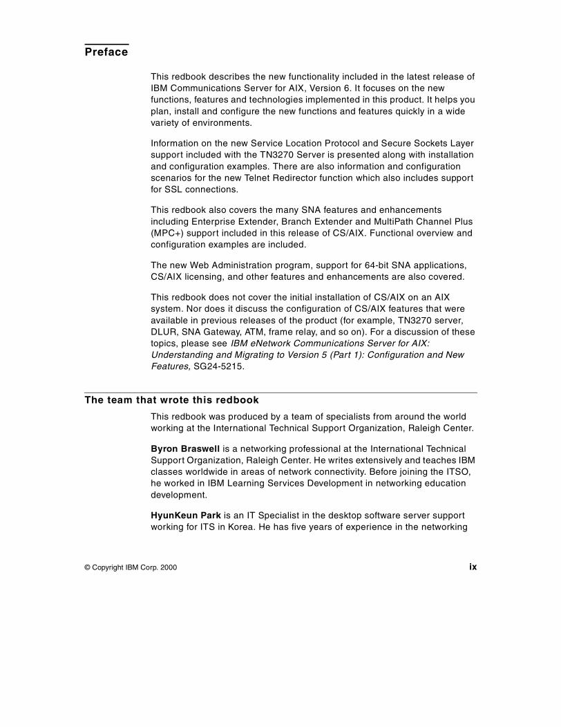
Preface
This redbook describes the new functionality included in the latest release ofIBM Communications Server for AIX, Version 6. It focuses on the newfunctions, features and technologies implemented in this product. It helps youplan, install and configure the new functions and features quickly in a widevariety of environments.
Information on the new Service Location Protocol and Secure Sockets Layersupport included with the TN3270 Server is presented along with installationand configuration examples. There are also information and configurationscenarios for the new Telnet Redirector function which also includes supportfor SSL connections.
This redbook also covers the many SNA features and enhancementsincluding Enterprise Extender, Branch Extender and MultiPath Channel Plus(MPC+) support included in this release of CS/AIX. Functional overview andconfiguration examples are included.
The new Web Administration program, support for 64-bit SNA applications,CS/AIX licensing, and other features and enhancements are also covered.
This redbook does not cover the initial installation of CS/AIX on an AIXsystem. Nor does it discuss the configuration of CS/AIX features that wereavailable in previous releases of the product (for example, TN3270 server,DLUR, SNA Gateway, ATM, frame relay, and so on). For a discussion of thesetopics, please see IBM eNetwork Communications Server for AIX:Understanding and Migrating to Version 5 (Part 1): Configuration and NewFeatures, SG24-5215.
The team that wrote this redbook
This redbook was produced by a team of specialists from around the worldworking at the International Technical Support Organization, Raleigh Center.
Byron Braswell is a networking professional at the International TechnicalSupport Organization, Raleigh Center. He writes extensively and teaches IBMclasses worldwide in areas of network connectivity. Before joining the ITSO,he worked in IBM Learning Services Development in networking educationdevelopment.
HyunKeun Park is an IT Specialist in the desktop software server supportworking for ITS in Korea. He has five years of experience in the networking
© Copyright IBM Corp. 2000 ix
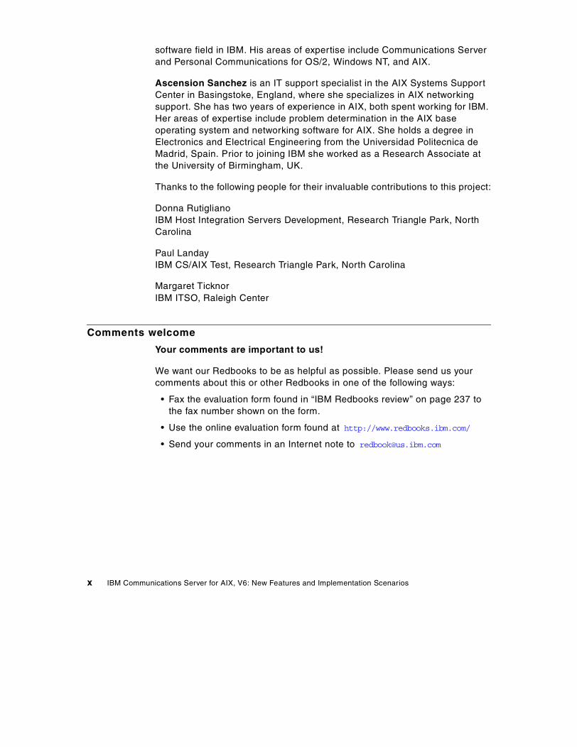
software field in IBM. His areas of expertise include Communications Serverand Personal Communications for OS/2, Windows NT, and AIX.
Ascension Sanchez is an IT support specialist in the AIX Systems SupportCenter in Basingstoke, England, where she specializes in AIX networkingsupport. She has two years of experience in AIX, both spent working for IBM.Her areas of expertise include problem determination in the AIX baseoperating system and networking software for AIX. She holds a degree inElectronics and Electrical Engineering from the Universidad Politecnica deMadrid, Spain. Prior to joining IBM she worked as a Research Associate atthe University of Birmingham, UK.
Thanks to the following people for their invaluable contributions to this project:
Donna RutiglianoIBM Host Integration Servers Development, Research Triangle Park, NorthCarolina
Paul LandayIBM CS/AIX Test, Research Triangle Park, North Carolina
Margaret TicknorIBM ITSO, Raleigh Center
Comments welcome
Your comments are important to us!
We want our Redbooks to be as helpful as possible. Please send us yourcomments about this or other Redbooks in one of the following ways:
• Fax the evaluation form found in “IBM Redbooks review” on page 237 tothe fax number shown on the form.
• Use the online evaluation form found at http://www.redbooks.ibm.com/
• Send your comments in an Internet note to [email protected]
x IBM Communications Server for AIX, V6: New Features and Implementation Scenarios

Part 1. Introduction
© Copyright IBM Corp. 2000 1

2 IBM Communications Server for AIX, V6: New Features and Implementation Scenarios
Chapter 1. Overview
IBM Communications Server for AIX, Version 6 brings the power of personalnetworking to your workstation. Whether it is for host terminal emulation,client/server and distributed applications, or connectivity across local andwide area networks (LANs and WANs), IBM Communications Server for AIXoffers a robust set of communications, networking and systems managementfeatures.
In this chapter, we provide an overview of the new features and functionsincluded in CS/AIX V6. For a review and detailed discussion of features andfunctions included in the previous release of Communications Server for AIX,please see IBM eNetwork Communications Server for AIX: Understandingand Migrating to Version 5: Part 1 - Configuration and New Features,SG24-5215.
1.1 Secure Sockets Layer support
CS/AIX provides support for Secure Sockets Layer (SSL) V3 connectionsbetween CS/AIX and telnet clients and/or IP hosts. The CS/AIX TN3270Eserver supports SSL connections to TN3270 clients while the TN Redirectorsupports SSL connections to Telnet clients and TN servers (3270 and 5250).This security uses SSL Version 3.0 to provide data encryption, serverauthentication and optional client authentication using signed certificates.The primary goal of the SSL is to provide private and reliable communicationsbetween two applications.
By using this SSL protocol, you can establish TCP/IP connections thatprovide the following security features:
• Message privacy (encryption of data)
• Message integrity (each packet arrives unaltered)
• Authentication (identity of remote nodes can be verified)
1.2 TN Redirector
The CS/AIX TN Redirector feature provides passthrough TCP/IP access tohost applications, such as 3270 applications and host printing applications,for TN3270, TN3270E, TN5250 and Virtual Terminal (VT) clients, referred tocollectively as Telnet clients. The Telnet user communicates with CS/AIX overa TCP/IP connection and CS/AIX then communicates with the host overanother TCP/IP connection.
© Copyright IBM Corp. 2000 3
TN Redirector also supports filters on which client workstations are allowedaccess to the host. Filtering can be done by fully qualified IP address or hostname. The default is to grant access to all clients.
1.3 Service Location Protocol
Service Location Protocol (SLP) is an Internet Engineering Task Force (IETF)proposed standard protocol that is designed to simplify the discovery and useof network resources. It allows SLP-enabled resources (TN3270E servers, forexample) to advertise their services. SLP-enabled clients automatically selectthe most appropriate server based on attributes (such as current load) of theserver.
As network IP environments become more dynamic in character, SLP willplay a major role in managing available network resources in theseenvironments.
IBM Communications Server for AIX, Version 6 provides TN3270E Serversupport for SLP. SLP-enabled TN3270 clients can automatically select theleast loaded CS/AIX TN3270E server based on server load parameters.
1.4 Enterprise Extender
Enterprise Extender (HPR/IP) provides High Performance Routing (HPR)functionality over IP connections to support SNA applications that areconnected over an IP network. It allows you to take advantage of the HPRbenefits in an IP-routed network, and participate as a full APPN node in anAPPN network.
HPR (which replaces intermediate session routing in APPN), is a routingtechnique that reduces processing overhead at intermediate nodes, reroutessessions around failed nodes and links non-disruptively, and regulates trafficflow by predicting and reducing congestion in the network.
HPR’s main components are:
• Rapid Transport Protocol (RTP), which allows a node to be the initiator orterminator of an HPR connection.
• Automatic Network Routing (ANR), which allows a node to act as anintermediary along the path of an HPR connection.
Enterprise Extender in CS/AIX is implemented simply as a communicationslink. To connect two SNA applications over IP, you define an Enterprise
4 IBM Communications Server for AIX, V6: New Features and Implementation Scenarios
Extender link, in the same way as for any other link type such as SDLC orEthernet.
1.5 Branch Extender
Network nodes in an APPN network need to maintain topology informationabout the location of other nodes in the network and the communicationslinks between them, and to forward this information around the network whenthe topology changes. As the network grows in size, the amount of storedinformation and topology-related network traffic can become large anddifficult to manage. The Branch Extender feature of APPN has beendeveloped to provide a solution to these problems.
As the name implies, Branch Extender is designed for networks that can bedivided into distinct areas such as separate branches of a large organization.It works by separating out branches from the main backbone APPN network(for example, the network in the organization's headquarters).
1.6 MPC+ support
Multipath Channel Plus (MPC+) provides support for High PerformanceRouting (HPR) connectivity over channel connections to host mainframecomputers running VTAM V4R4 or later.
The ESCON adapter card required for MPC+ support enables an AIX systemto appear to the host as one or more ESCON control units.
1.7 Web administration
IBM Communications Server for AIX, Version 6 includes a new tool toadminister the CS/AIX configuration: the Web Administration program. Itallows you to administer CS/AIX from a browser without the need to start an Xsession or telnet session to the CS/AIX server, and is particularly useful whenconnecting over slow or unreliable links.
With your Internet browser, you can access your CS/AIX configuration,register new resources, and manage them from around the world.
Administration functions are similar to those provided by the Motifadministration program.
Chapter 1. Overview 5
1.8 CS/AIX licensing
CS/AIX licensing is based on the number of concurrent users of the product.New functions are provided to record information about the current and peakusage of CS/AIX resources. You can use these functions to help determinewhether your usage is within the limits permitted by your license.
1.9 CS/AIX documentation
Product documentation for CS/AIX now includes AIX docsearch indices. Thisallows a user with a Web browser and connectivity to the CS/AIX server toaccess and search all CS/AIX softcopy documentation for specific keywords.
1.10 64-bit application support
SNA applications using the CS/AIX APIs can be compiled and linked to run ineither 32-bit mode or 64-bit mode. This allows SNA applications to takeadvantage of 64-bit hardware features such as large file, addressing andmemory support.
1.11 Java CPI-C API
CS/AIX includes support to develop and implement Java object-orientedapplications using the Common Programming Interface for Communications(CPI-C) API. This is in addition to the current support in CS/AIX for CPI-C APIsupport for applications written in the C language.
CPI-C for Java is an object-oriented version of the x/open standard interfaceto the IBM SNA LU 6.2 for developing SNA applications. The basic goal ofincluding Java CPI-C is to enable programmers to access classic SNAapplications where corporate data is traditionally stored. A programmerfamiliar with standard CPI-C or APPC, who is also comfortable withobject-oriented programming (for example in C++ or Java) will feelcomfortable with the Java CPI-C API.
6 IBM Communications Server for AIX, V6: New Features and Implementation Scenarios

Part 2. Telnet services and enhancements
© Copyright IBM Corp. 2000 7

8 IBM Communications Server for AIX, V6: New Features and Implementation Scenarios
Chapter 2. Secure Sockets Layer support
This chapter introduces the Secure Sockets Layer (SSL) function of IBMCommunications Server for AIX, Version 6. CS/AIX supports secureconnections between Telnet clients and a CS/AIX TN3270E server. Inaddition, the CS/AIX TN Redirector supports both upstream and downstreamSSL connections.
CS/AIX Secure Sockets Layer uses SSL Version 3 to provide data encryptionand server/client authentication using signed certificates. The primary goal ofthe SSL protocol is to provide private and reliable communications betweentwo applications. In the following sections, we’ll discuss the concept of SSLand the way it securely handles data between a Telnet server and its clients.
2.1 Secure Sockets Layer (SSL) overview
SSL is an industry-standard protocol originally developed by NetscapeCommunications Corporation. It defines a method of providing a privatechannel between client and server that ensures privacy of data,authentication of the session partners, and message integrity.
• Privacy requires that the information flowing between client and servercannot be read by anyone else
• Authentication ensures that the partners are actually who they say theyare
• Integrity ensures that information sent is not modified in transmission.
To achieve this, SSL uses three cryptographic techniques:
• Symmetric-key encryption
• Public-key encryption
• Hashing functions
We describe each of these techniques below:
2.1.1 Symmetric-key encryptionSymmetric-key encryption uses a single key, which must be known to bothclient and server, to encrypt and decrypt messages. It is very fast and secure,and for this reason is used for most encryption. However, a limitation ofsymmetric-key encryption is that the key must be passed between server andclient before secure transmission starts.
© Copyright IBM Corp. 2000 9
2.1.2 Public-key encryptionPublic-key encryption uses a pair of keys, a public key and a private key. Theserver’s public key is published, and the private key is kept secret. To send asecure message to the server, the client encrypts the message using theserver’s public key. When the server receives the message, it decrypts themessage using its private key. The message is secure because it cannot bedecrypted by means of the public key. Public key encryption has a bigadvantage over the symmetric-key approach in that no secret key needs to betransmitted. However, it requires much more processing power thansymmetric-key encryption.
2.1.3 Hashing functionsHashing functions are used to ensure message integrity. The messagesender applies a hashing function to the message to create a messagedigest, which it sends with the message. The receiver applies the samealgorithm to the message and compares the two digests. If they are identical,it proves that the message has not been tampered with during transmission.
SSL uses these techniques to provide its three basic security services:
• Message privacy is achieved through a combination of public-key andsymmetric-key encryption. During session setup, a symmetric key iscreated using information exchanged using public-key encryption. Oncethe session is initiated, all traffic between client and server is encryptedusing symmetric-key encryption and the key negotiated during sessionsetup. In this way, SSL exploits the advantages of both symmetric andpublic-key encryption to ensure message privacy.
• The message integrity service ensures that messages cannot be changedin transit without detection. SSL uses hash functions to ensure messageintegrity.
• Mutual authentication is the process whereby the client and the serverconvince each other of their identities. The client and server identities areencoded in public-key certificates.
2.2 Public-key certificates
Public-key encryption provides a powerful way by which information can besent across the Internet in encrypted form without the decoding key (theprivate key) ever having to be transmitted. However, how can you be sure thatthe owner of the public key is really who it claims to be?
10 IBM Communications Server for AIX, V6: New Features and Implementation Scenarios
The public-key certificate is a means of guaranteeing the integrity of a publickey.
Public-key certificates are special files adhering to the X.509 standard andissued by a certifying authority (CA). Being in a standard form, they can berecognized and validated by software, and they are, of course, tamper proof.
A public-key certificate contains the following identifying components:
• The subject’s distinguished name, which consists of the common name, orhost name, of the Web site (server) that will use the certificate - forexample, rs60030.itso.ral.ibm.com
• The organization name - for example, IBM
• Optionally, an organization unit - for example, ITSO
• Optionally, a city or locality - for example, Raleigh
• Optionally, a state or province - for example, NC
• A country code of at least two characters - for example, US
• The issuer’s distinguished name
• The subject’s public key
• The issuer’s signature
• A validity period
• A serial number
The certificate tells you that the CA confirms that the public key belongs tothe organization identified by the distinguished name.
SSL has been implemented in IBM Communications Server for AIX to supportestablishment of secure sessions between Telnet clients and the TN3270Eserver and/or TN Redirector.
Clients that support SSL V3 encryption are IBM Personal Communications forWindows 95 and Windows NT Version 4.3 and IBM Host On-Demand Version2.0 and later. The IETF TN3270 working group has indicated that SSL V3 isthe protocol of choice while addressing the security issues between TNclients and servers.
2.3 SSL implementation in CS/AIX
The TN3270E Server and TN Redirector functions of IBM CommunicationsServer for AIX, Version 6 support SSL connections.
Chapter 2. Secure Sockets Layer support 11
To establish an SSL connection, you must do the following:
1. Install SSL support for CS/AIX
2. Enable SSL in the TN3270 server and/or TN Redirector configuration
3. Execute the Key Management utility to manage certificates
4. Decide what type of certificate to use
5. Decide what type of authentication to use
2.3.1 Install SSL support for CS/AIXVersion 4.3.2-ML2 or later of the AIX operating system is required to supportCS/AIX SSL configurations.
Secure Sockets Layer support for CS/AIX requires installation of additionalfilesets that are included with the CS/AIX distribution media. The followingfilesets are included with CS/AIX for SSL support:
gskit.rte AIX Certificate and SSL Base Runtime. The gskit.rtefileset must be at the 4.0.3.42 level or later.
sna.strong_sec.tnssl Strong security, available in the United States andCanada. Depending on your location, you may or maynot have the strong security fileset because it is notavailable in your country.
If you want to use SSL with TN server or TN Redirector, you must install theAIX Certificate and SSL Base Runtime fileset. If you want to use strongsecurity, and the additional fileset is available, you must install it in addition tothe AIX Certificate and SSL Base Runtime fileset.
2.3.2 Enable SSL in TN3270 server/TN Redirector
2.3.2.1 TN3270 serverTo configure a secure TN3270 server, proceed as if you were configuring anormal TN3270 server.
For more information on how to perform the normal TN3270 serverconfiguration, refer to IBM Communications Server for AIX AdministrationGuide Version 6, SC31-8586, or IBM eNetwork Communications Server forAIX: Understanding and Migrating to Version 5: Part 1 - Configuration andNew Features, SG24-5215.
From the main CS/AIX node panel, select:
Services -> TN Server -> TN Server
12 IBM Communications Server for AIX, V6: New Features and Implementation Scenarios
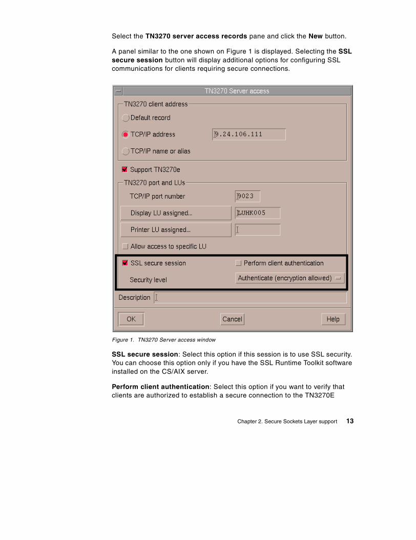
Select the TN3270 server access records pane and click the New button.
A panel similar to the one shown on Figure 1 is displayed. Selecting the SSLsecure session button will display additional options for configuring SSLcommunications for clients requiring secure connections.
Figure 1. TN3270 Server access window
SSL secure session: Select this option if this session is to use SSL security.You can choose this option only if you have the SSL Runtime Toolkit softwareinstalled on the CS/AIX server.
Perform client authentication: Select this option if you want to verify thatclients are authorized to establish a secure connection to the TN3270E
Chapter 2. Secure Sockets Layer support 13
server. Client Authentication also enables you to use Certificate RevocationList (CRL) support by configuring the location of a Lightweight DirectoryAccess Protocol (LDAP) Server where the CRL is stored. This information isentered in the SSL Client Revocation dialog window. You can choose thisoption only if you have chosen SSL secure session.
Configuring the LDAP server for CRL support is not covered in this document.Please see the documentation for the specific LDAP server being used for theneeded configuration information.
Security Level: This option allows you to specify the security level thatclients must use in order to establish a connection to the TN3270E server.You can choose this option only if you have chosen SSL secure session.See Figure 2 on page 15 for a display of the available security level options.
2.3.2.2 TN RedirectorTo configure a secure TN Redirector, proceed as if you were configuring anormal TN Redirector. See Chapter 3, “TN Redirector” on page 33 forconfiguration assistance.
• Click Services -> TN Server -> TN Server.
• Select the TN Redirector access records pane and click on the Newbutton.
A panel similar to the one shown in Figure 2 on page 15 is displayed. Notethat the SSL secure session button is displayed for both the clientconnection and the host connection. Selecting this button displays additionaloptions for configuring SSL communications.
14 IBM Communications Server for AIX, V6: New Features and Implementation Scenarios
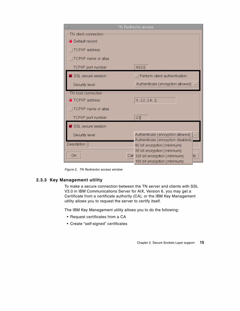
Figure 2. TN Redirector access window
2.3.3 Key Management utilityTo make a secure connection between the TN server and clients with SSLV3.0 in IBM Communications Server for AIX, Version 6, you may get aCertificate from a certificate authority (CA), or the IBM Key Managementutility allows you to request the server to certify itself.
The IBM Key Management utility allows you to do the following:
• Request certificates from a CA
• Create “self-signed” certificates
Chapter 2. Secure Sockets Layer support 15
• Store, export, and import certificates
All these certificates adhere to the X.509 standard (either V1, 2, or 3).
Use of the IBM Key Management utility is discussed in “Configuring SSLsecurity” on page 19.
2.3.4 Deciding what type of certificates to useThere are three types of certificates available for use when setting up SSL forTN server with CS/AIX. One type of certificate, self-signed, can be generatedby the user. The other two types of certificates, well-known and unknown,require the user to request a certificate from a certificate provider. The type ofenvironment the user will be implementing will dictate the type of certificatethe user should use. The following is a brief description of each type ofcertificate that will aid the user in deciding what type of certificate is best forthem.
2.3.4.1 Self-signed certificatesReceipt of a certificate from a well-known trusted CA can take up to threeweeks. Until you receive the public server certificate(s), you can create aself-signed certificate by using the IBM Key Management database, to enableSSL sessions between clients and the server. A self-signed certificate shouldbe used for controlled testing purposes only. To ensure adequate security foryour site, a self-signed certificate should not be used in a productionenvironment.
2.3.4.2 Certificates from a well-known trusted certificate authorityA well-known trusted certificate authority (CA) is one that is widely known andtrusted by the user community. Signer (CA root) certificates for well-knowntrusted CAs are present by default in the IBM Key Management database andwill also be present in the key databases of most other SSL-enabledapplications. In practical terms, this means that every user will have the publickey of each well-known CA and will have their software configured to trust theCA. This allows the user’s software to automatically check the validity on anycertificate issued by a well-known CA without further configuration.
Using well-known certificates requires the user to contact a well-known CAprovider (for example Verisign or Thawte) and apply for the additionalcertificate(s) the user needs. Certificates from a well-known CA are adequatefor a production environment.
16 IBM Communications Server for AIX, V6: New Features and Implementation Scenarios
2.3.4.3 Certificates from an unknown CAA certificate issued by an unknown CA is termed unknown because thesigner (CA root) certificate is not already present in the IBM Key Managementdatabase. This will be the case if the user decides to purchase a certificatefrom a CA whose signer (CA root) certificate is not already present in thedatabase, or if the user does not want to depend on an outside vendor toprovide certificates. The user can purchase software such as IBM VaultRegistry to generate certificates for their secure environment. Certificatesgenerated from an unknown CA or generated by IBM Vault Registry softwareare adequate for a production environment.
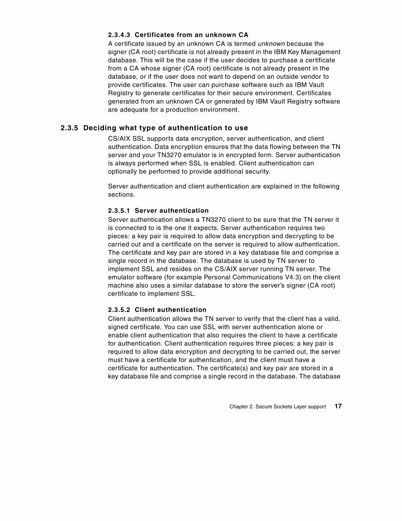
2.3.5 Deciding what type of authentication to useCS/AIX SSL supports data encryption, server authentication, and clientauthentication. Data encryption ensures that the data flowing between the TNserver and your TN3270 emulator is in encrypted form. Server authenticationis always performed when SSL is enabled. Client authentication canoptionally be performed to provide additional security.
Server authentication and client authentication are explained in the followingsections.
2.3.5.1 Server authenticationServer authentication allows a TN3270 client to be sure that the TN server itis connected to is the one it expects. Server authentication requires twopieces: a key pair is required to allow data encryption and decrypting to becarried out and a certificate on the server is required to allow authentication.The certificate and key pair are stored in a key database file and comprise asingle record in the database. The database is used by TN server toimplement SSL and resides on the CS/AIX server running TN server. Theemulator software (for example Personal Communications V4.3) on the clientmachine also uses a similar database to store the server’s signer (CA root)certificate to implement SSL.
2.3.5.2 Client authenticationClient authentication allows the TN server to verify that the client has a valid,signed certificate. You can use SSL with server authentication alone orenable client authentication that also requires the client to have a certificatefor authentication. Client authentication requires three pieces: a key pair isrequired to allow data encryption and decrypting to be carried out, the servermust have a certificate for authentication, and the client must have acertificate for authentication. The certificate(s) and key pair are stored in akey database file and comprise a single record in the database. The database
Chapter 2. Secure Sockets Layer support 17
on the CS/AIX server is used by TN server to implement SSL. The emulatorsoftware (for example IBM Personal Communications V4.3) on the clientmachine also uses a similar database to store the necessary certificate(s) toimplement SSL.
2.4 Scenario
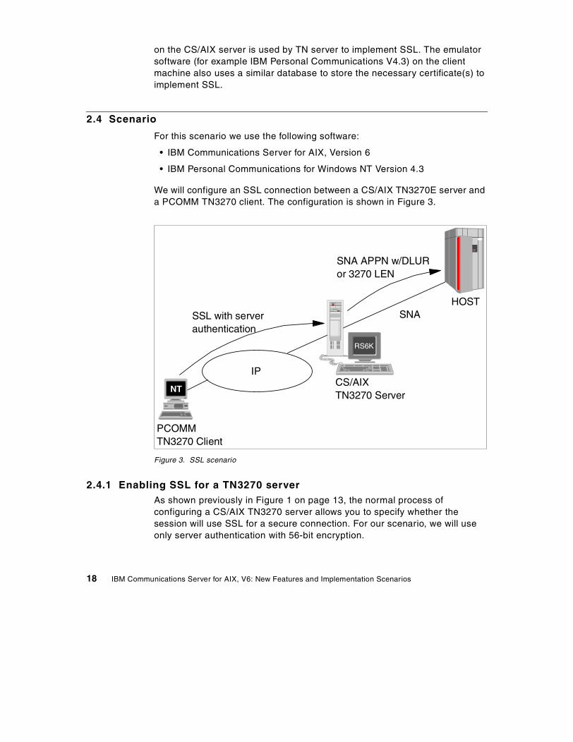
For this scenario we use the following software:
• IBM Communications Server for AIX, Version 6
• IBM Personal Communications for Windows NT Version 4.3
We will configure an SSL connection between a CS/AIX TN3270E server anda PCOMM TN3270 client. The configuration is shown in Figure 3.
Figure 3. SSL scenario
2.4.1 Enabling SSL for a TN3270 serverAs shown previously in Figure 1 on page 13, the normal process ofconfiguring a CS/AIX TN3270 server allows you to specify whether thesession will use SSL for a secure connection. For our scenario, we will useonly server authentication with 56-bit encryption.
HOST
SNA APPN w/DLURor 3270 LEN
CS/AIXTN3270 Server
PCOMMTN3270 Client
NT
RS6K
SSL with serverauthentication
IP
SNA
18 IBM Communications Server for AIX, V6: New Features and Implementation Scenarios

For more information on how to perform the basic TN3270 serverconfiguration, refer to IBM Communications Server for AIX AdministrationGuide Version 6, SC31-8586, or IBM eNetwork Communications Server forAIX: Understanding and Migrating to Version 5: Part 1 - Configuration andNew Features, SG24-5215.
2.4.2 Configuring SSL securityThe key database file on the CS/AIX server is managed by the IBM KeyManagement utility. Running the executable for it, snakeyman, will launch aJava graphical user interface program. Before you can run the utility, you willneed to export the JAVA_HOME environment variable with the followingcommand:
export JAVA_HOME=/usr/jdk_base
where /usr/jdk_base is the directory where Java 1.1.6 or later is installed.
In addition there may be a need to export the DISPLAY environment variable.Once the export(s) have been run, type:
snakeyman
and the database GUI will open. The IBM Key Management window shown inFigure 4 will be displayed.
Chapter 2. Secure Sockets Layer support 19
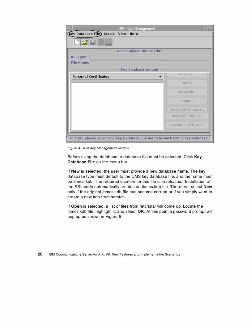
Figure 4. IBM Key Management window
Before using the database, a database file must be selected. Click KeyDatabase File on the menu bar.
If New is selected, the user must provide a new database name. The keydatabase type must default to the CMS key database file, and the name mustbe ibmcs.kdb. The required location for this file is in /etc/sna/. Installation ofthe SSL code automatically creates an ibmcs.kdb file. Therefore, select Newonly if the original ibmcs.kdb file has become corrupt or if you simply want tocreate a new kdb from scratch.
If Open is selected, a list of files from /etc/sna/ will come up. Locate theibmcs.kdb file, highlight it, and select OK. At this point a password prompt willpop up as shown in Figure 5.
20 IBM Communications Server for AIX, V6: New Features and Implementation Scenarios
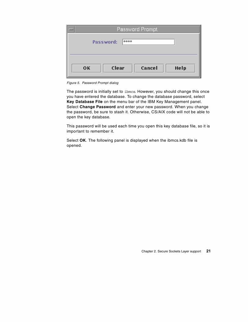
Figure 5. Password Prompt dialog
The password is initially set to ibmcs. However, you should change this onceyou have entered the database. To change the database password, selectKey Database File on the menu bar of the IBM Key Management panel.Select Change Password and enter your new password. When you changethe password, be sure to stash it. Otherwise, CS/AIX code will not be able toopen the key database.
This password will be used each time you open this key database file, so it isimportant to remember it.
Select OK. The following panel is displayed when the ibmcs.kdb file isopened.
Chapter 2. Secure Sockets Layer support 21
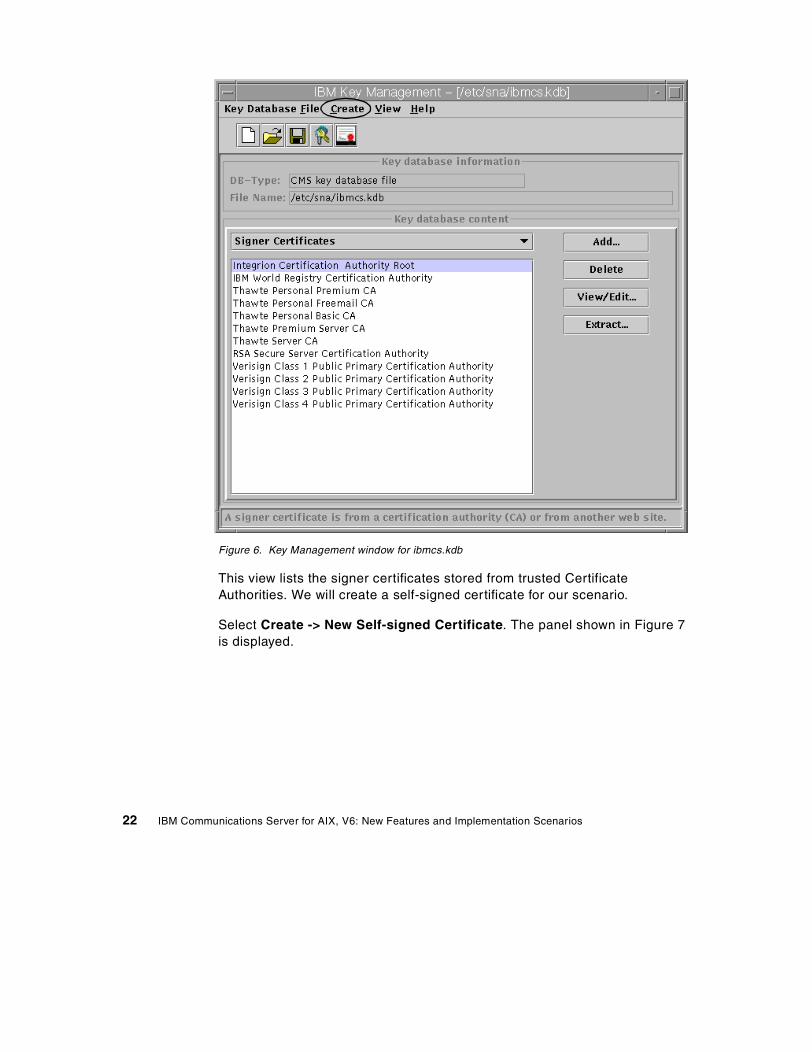
Figure 6. Key Management window for ibmcs.kdb
This view lists the signer certificates stored from trusted CertificateAuthorities. We will create a self-signed certificate for our scenario.
Select Create -> New Self-signed Certificate. The panel shown in Figure 7is displayed.
22 IBM Communications Server for AIX, V6: New Features and Implementation Scenarios
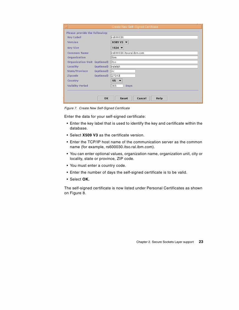
Figure 7. Create New Self-Signed Certificate
Enter the data for your self-signed certificate:
• Enter the key label that is used to identify the key and certificate within thedatabase.
• Select X509 V3 as the certificate version.
• Enter the TCP/IP host name of the communication server as the commonname (for example, rs600030.itso.ral.ibm.com).
• You can enter optional values, organization name, organization unit, city orlocality, state or province, ZIP code.
• You must enter a country code.
• Enter the number of days the self-signed certificate is to be valid.
• Select OK.
The self-signed certificate is now listed under Personal Certificates as shownon Figure 8.
Chapter 2. Secure Sockets Layer support 23
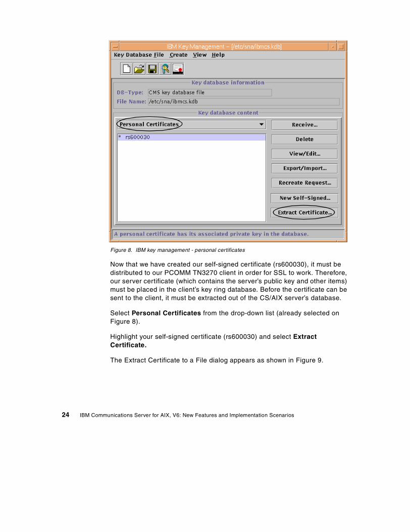
Figure 8. IBM key management - personal certificates
Now that we have created our self-signed certificate (rs600030), it must bedistributed to our PCOMM TN3270 client in order for SSL to work. Therefore,our server certificate (which contains the server’s public key and other items)must be placed in the client’s key ring database. Before the certificate can besent to the client, it must be extracted out of the CS/AIX server’s database.
Select Personal Certificates from the drop-down list (already selected onFigure 8).
Highlight your self-signed certificate (rs600030) and select ExtractCertificate.
The Extract Certificate to a File dialog appears as shown in Figure 9.
24 IBM Communications Server for AIX, V6: New Features and Implementation Scenarios
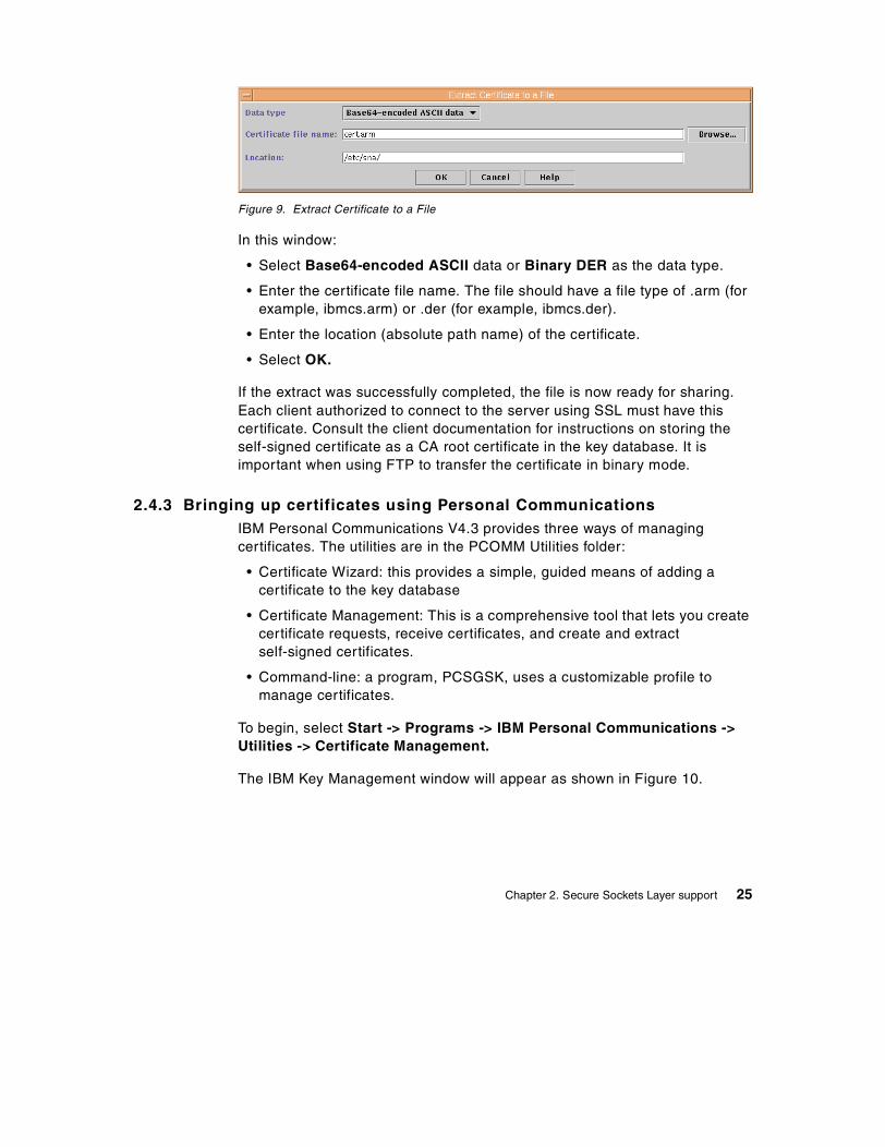
Figure 9. Extract Certificate to a File
In this window:
• Select Base64-encoded ASCII data or Binary DER as the data type.
• Enter the certificate file name. The file should have a file type of .arm (forexample, ibmcs.arm) or .der (for example, ibmcs.der).
• Enter the location (absolute path name) of the certificate.
• Select OK.
If the extract was successfully completed, the file is now ready for sharing.Each client authorized to connect to the server using SSL must have thiscertificate. Consult the client documentation for instructions on storing theself-signed certificate as a CA root certificate in the key database. It isimportant when using FTP to transfer the certificate in binary mode.
2.4.3 Bringing up certificates using Personal CommunicationsIBM Personal Communications V4.3 provides three ways of managingcertificates. The utilities are in the PCOMM Utilities folder:
• Certificate Wizard: this provides a simple, guided means of adding acertificate to the key database
• Certificate Management: This is a comprehensive tool that lets you createcertificate requests, receive certificates, and create and extractself-signed certificates.
• Command-line: a program, PCSGSK, uses a customizable profile tomanage certificates.
To begin, select Start -> Programs -> IBM Personal Communications ->Utilities -> Certificate Management.
The IBM Key Management window will appear as shown in Figure 10.
Chapter 2. Secure Sockets Layer support 25
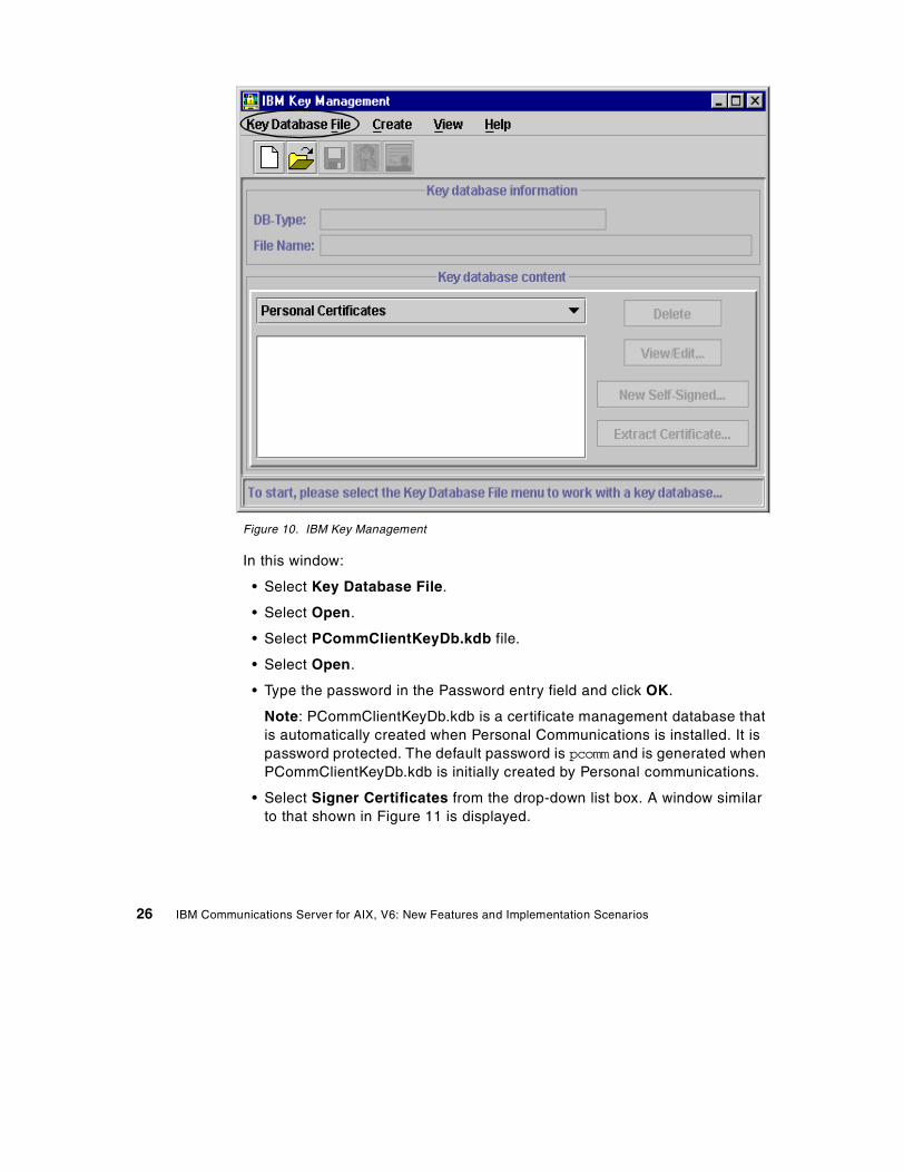
Figure 10. IBM Key Management
In this window:
• Select Key Database File.
• Select Open.
• Select PCommClientKeyDb.kdb file.
• Select Open.
• Type the password in the Password entry field and click OK.
Note: PCommClientKeyDb.kdb is a certificate management database thatis automatically created when Personal Communications is installed. It ispassword protected. The default password is pcomm and is generated whenPCommClientKeyDb.kdb is initially created by Personal communications.
• Select Signer Certificates from the drop-down list box. A window similarto that shown in Figure 11 is displayed.
26 IBM Communications Server for AIX, V6: New Features and Implementation Scenarios
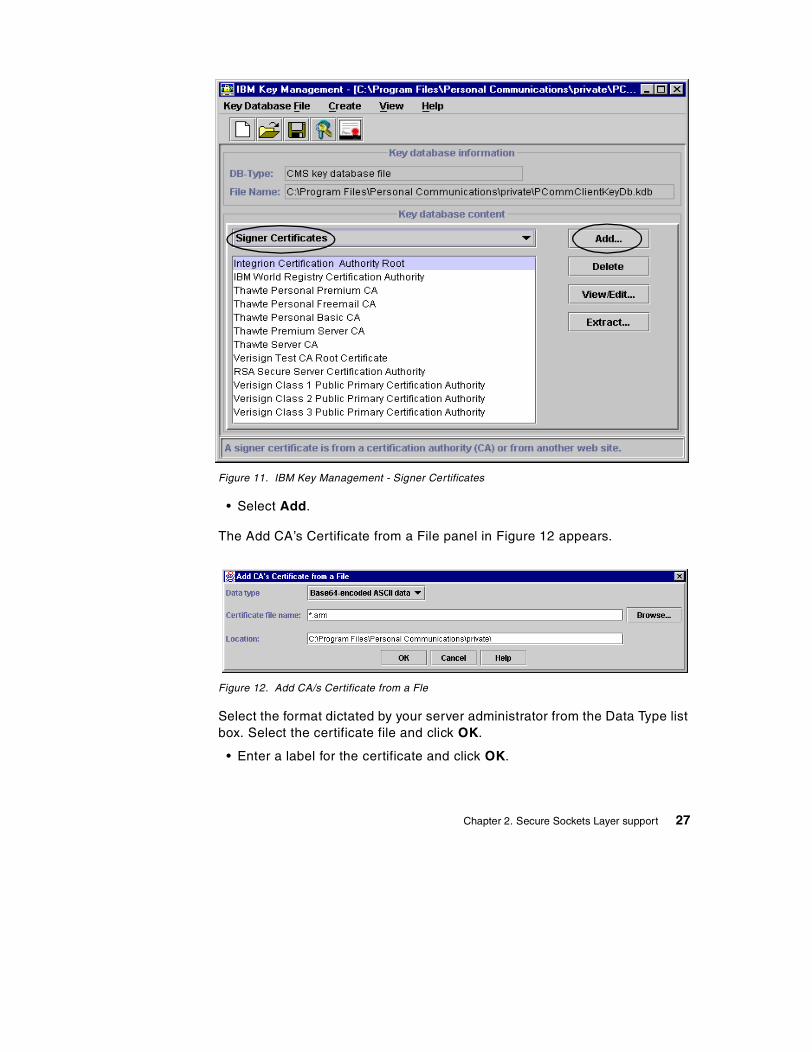
Figure 11. IBM Key Management - Signer Certificates
• Select Add.
The Add CA’s Certificate from a File panel in Figure 12 appears.
Figure 12. Add CA/s Certificate from a Fle
Select the format dictated by your server administrator from the Data Type listbox. Select the certificate file and click OK.
• Enter a label for the certificate and click OK.
Chapter 2. Secure Sockets Layer support 27
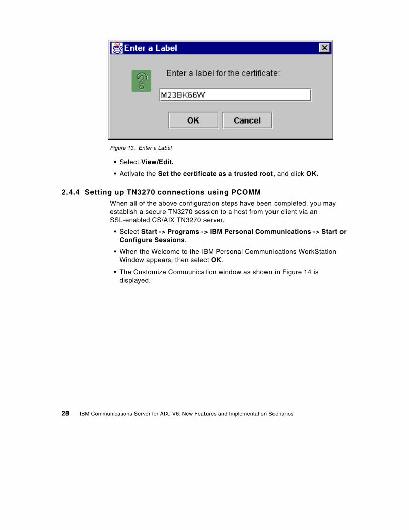
Figure 13. Enter a Label
• Select View/Edit.
• Activate the Set the certificate as a trusted root, and click OK.
2.4.4 Setting up TN3270 connections using PCOMMWhen all of the above configuration steps have been completed, you mayestablish a secure TN3270 session to a host from your client via anSSL-enabled CS/AIX TN3270 server.
• Select Start -> Programs -> IBM Personal Communications -> Start orConfigure Sessions.
• When the Welcome to the IBM Personal Communications WorkStationWindow appears, then select OK.
• The Customize Communication window as shown in Figure 14 isdisplayed.
28 IBM Communications Server for AIX, V6: New Features and Implementation Scenarios
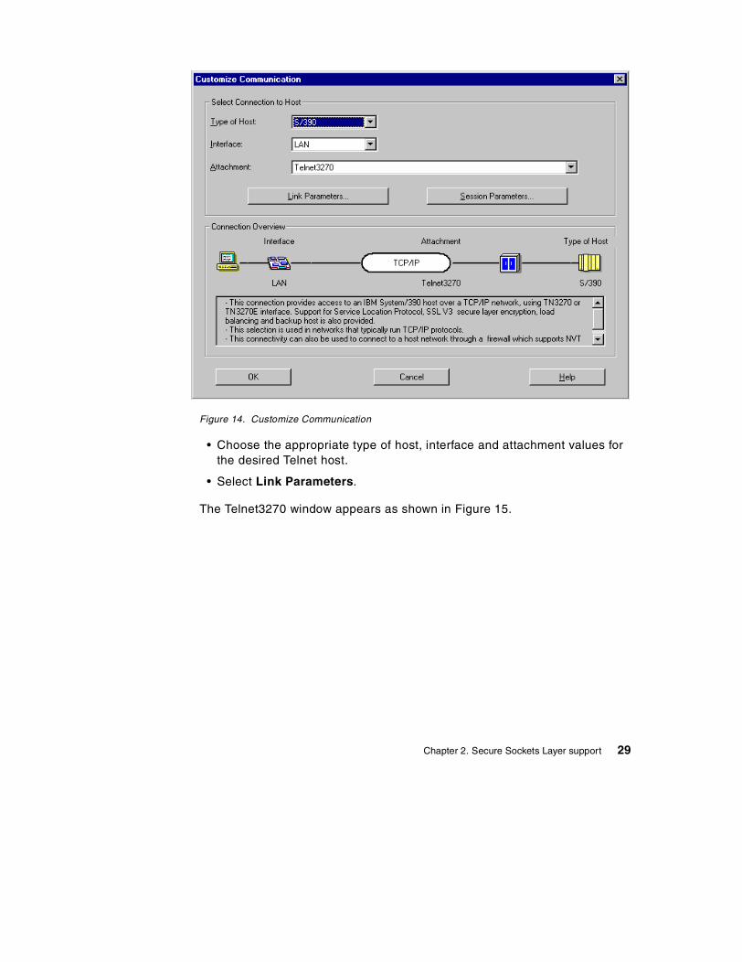
Figure 14. Customize Communication
• Choose the appropriate type of host, interface and attachment values forthe desired Telnet host.
• Select Link Parameters.
The Telnet3270 window appears as shown in Figure 15.
Chapter 2. Secure Sockets Layer support 29
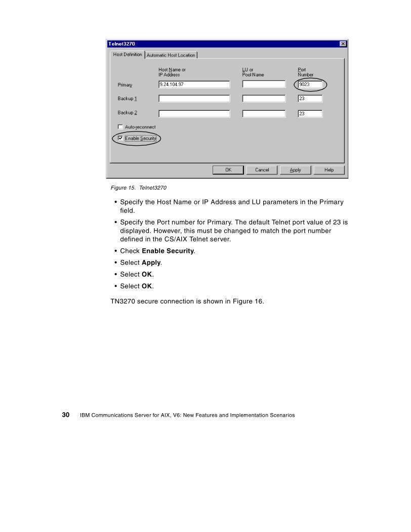
Figure 15. Telnet3270
• Specify the Host Name or IP Address and LU parameters in the Primaryfield.
• Specify the Port number for Primary. The default Telnet port value of 23 isdisplayed. However, this must be changed to match the port numberdefined in the CS/AIX Telnet server.
• Check Enable Security.
• Select Apply.
• Select OK.
• Select OK.
TN3270 secure connection is shown in Figure 16.
30 IBM Communications Server for AIX, V6: New Features and Implementation Scenarios
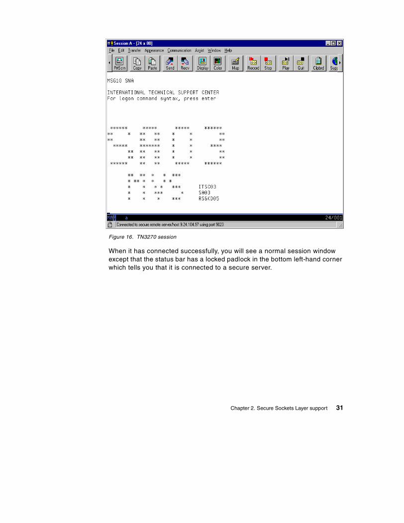
Figure 16. TN3270 session
When it has connected successfully, you will see a normal session windowexcept that the status bar has a locked padlock in the bottom left-hand cornerwhich tells you that it is connected to a secure server.
Chapter 2. Secure Sockets Layer support 31

32 IBM Communications Server for AIX, V6: New Features and Implementation Scenarios
Chapter 3. TN Redirector
This chapter describes the functionality of the TN Redirector and how it isconfigured, and provides two example scenarios that illustrate the use of TNRedirector in its simplest form, without SSL (Secure Sockets Layer).
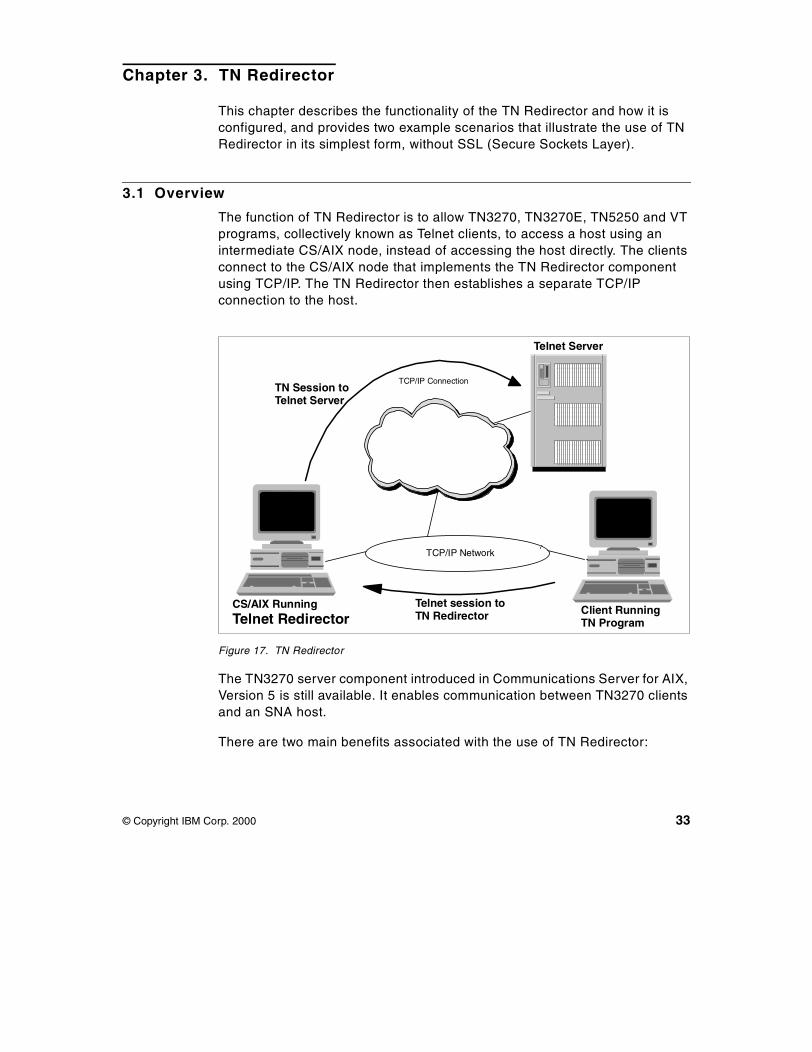
3.1 Overview
The function of TN Redirector is to allow TN3270, TN3270E, TN5250 and VTprograms, collectively known as Telnet clients, to access a host using anintermediate CS/AIX node, instead of accessing the host directly. The clientsconnect to the CS/AIX node that implements the TN Redirector componentusing TCP/IP. The TN Redirector then establishes a separate TCP/IPconnection to the host.
Figure 17. TN Redirector
The TN3270 server component introduced in Communications Server for AIX,Version 5 is still available. It enables communication between TN3270 clientsand an SNA host.
There are two main benefits associated with the use of TN Redirector:
Client RunningTN Program
TCP/IP Network
CS/AIX RunningTelnet Redirector
Telnet Server
Telnet session toTN Redirector
TN Session toTelnet Server
TCP/IP Connection
© Copyright IBM Corp. 2000 33
1. Having a large number of clients connecting directly to the host systemintroduces a potential security risk. By using a TN Redirector that passesconnections to the host, you can hide the address of the host from theclient users.
2. It provides SSL (Secure Sockets Layer) support.
SSL is explained in Chapter 2, “Secure Sockets Layer support” on page 9. Itenables encryption and authentication for client and host TCP/IPconnections.
To use SSL the GSK Runtime Toolkit component of CS/AIX must be installedand AIX must be at Level 4.3.2-ML2 or above. For software requirements seeIBM Communications Server for AIX, Version 6, Quick Beginnings,GC31-8583.
3.2 Implementation
TN Redirector support in CS/AIX requires AIX V4.3.2-ML2 or later.
The steps to configure the TN Redirector are:
1. Configure the node
2. Start the node
3. Configure TN Redirector access records
The first two steps are covered in IBM Communications Server for AIX,Version 6, Quick Beginnings, GC31-8583.
TN Redirector access records identify which Telnet clients are permitted toaccess the TN Redirector, the TCP/IP port that the client uses to connect toCS/AIX, the TCP/IP port that CS/AIX uses to connect to the host, the TCP/IPaddress of the host, and the SSL security settings.
You must create an access record for every TN server/port to which you wantan emulator to connect.
Multiple TN Redirector records may be defined to support access to multiplehosts using different ports. They can be implemented using different securityrequirements for different clients and hosts. As shown in Figure 18 on page35, Secure Sockets Layer (SSL) can be implemented between the client andthe Telnet Redirector and/or between the TN Redirector and the SSL-capableTelnet server such as CS for OS/390, AS/400, or CS/NT.
34 IBM Communications Server for AIX, V6: New Features and Implementation Scenarios
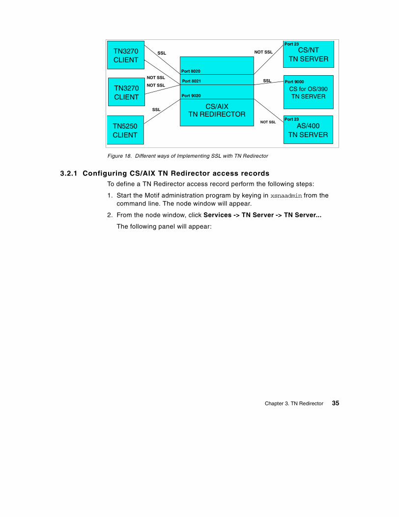
Figure 18. Different ways of Implementing SSL with TN Redirector
3.2.1 Configuring CS/AIX TN Redirector access recordsTo define a TN Redirector access record perform the following steps:
1. Start the Motif administration program by keying in xsnaadmin from thecommand line. The node window will appear.
2. From the node window, click Services -> TN Server -> TN Server...
The following panel will appear:
TN3270CLIENT
TN3270CLIENT
TN5250CLIENT
CS/AIXTN REDIRECTOR
CS/NTTN SERVER
CS for OS/390TN SERVER
AS/400TN SERVER
SSL
Port 8020
Port 23
Port 8021 Port 9000SSL
SSL
Port 9020
Port 23
NOT SSL
NOT SSL
NOT SSL
NOT SSL
Chapter 3. TN Redirector 35
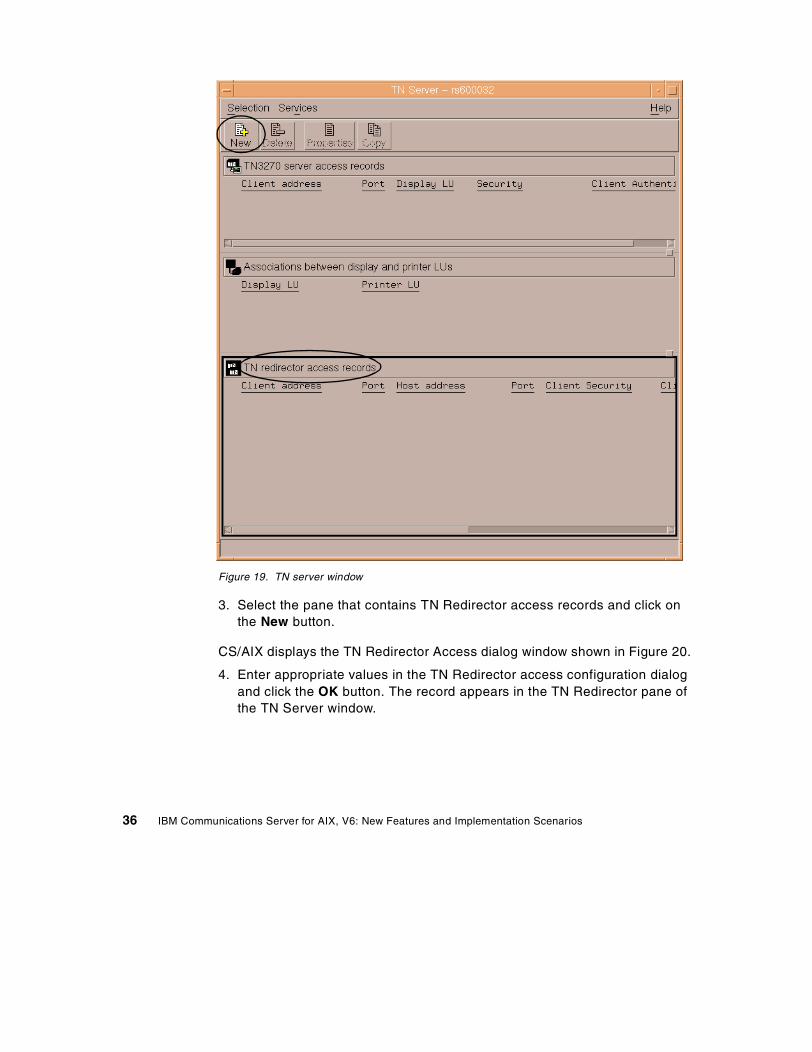
Figure 19. TN server window
3. Select the pane that contains TN Redirector access records and click onthe New button.
CS/AIX displays the TN Redirector Access dialog window shown in Figure 20.
4. Enter appropriate values in the TN Redirector access configuration dialogand click the OK button. The record appears in the TN Redirector pane ofthe TN Server window.
36 IBM Communications Server for AIX, V6: New Features and Implementation Scenarios
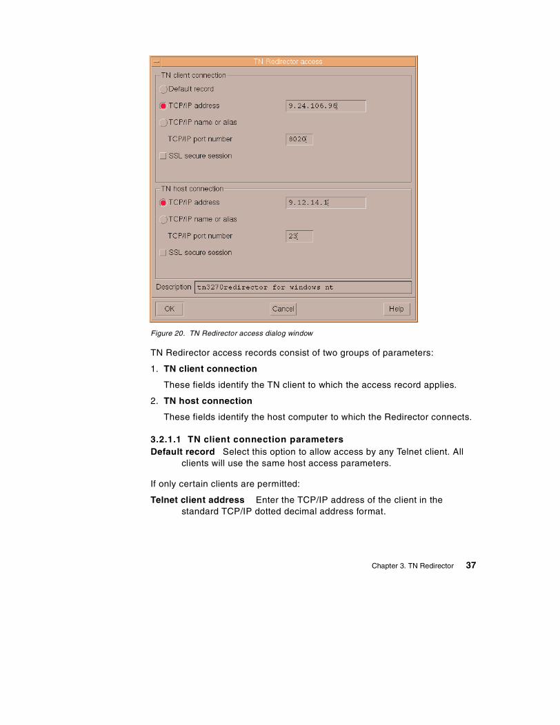
Figure 20. TN Redirector access dialog window
TN Redirector access records consist of two groups of parameters:
1. TN client connection
These fields identify the TN client to which the access record applies.
2. TN host connection
These fields identify the host computer to which the Redirector connects.
3.2.1.1 TN client connection parametersDefault record Select this option to allow access by any Telnet client. All
clients will use the same host access parameters.
If only certain clients are permitted:
Telnet client address Enter the TCP/IP address of the client in thestandard TCP/IP dotted decimal address format.
Chapter 3. TN Redirector 37
TCP/IP name or alias If you know the TCP/IP name of the TN client, youcan select this option and enter the name.
TCP/IP port number The TCP/IP port number to which the TN clientconnects on the TN Redirector.
Note:Use of the port number 23 is likely to clash with the AIX Telnetservice. Examine the /etc/services file and use the netstat -ancommand to choose a port number that is not in use by AIX. Specifythis port number when you start the TN client.
SSL secure session Select this option if this session is to use SSL toaccess the TN Redirector. Both the TN client and the TN Redirectoraccess record must be configured to use SSL.
Perform client authentication The client must send a valid certificateidentifying it as a valid client authorized to use the TN Redirector. Aswell as checking that the certificate is valid, the TN Redirector mayalso need to check the certificate against a certificate revocation liston an external LDAP server, to ensure that the user’s authorizationhas not been revoked. To specify how to access this server, from theTN Server window click Services -> SSL Client Revocation ->Check Certificate Revocation List.
Security level Select this option to specify the security level that clientsmust use in order to establish a connection to the TN Redirector.Possible values are:
• Authenticate Only (only TN Redirector authentication, noencryption),• 40 bit minimum - at least 40 bits• 56 bit minimum - at least 56 bits• 128 bit minimum - at least 128 bits• 168 bit minimum - at least 168 bits• Authenticate minimum - any of the above
The session will use the highest security level that both client and TNRedirector can support. If the client cannot support the requestedlevel of security or higher the session will not be started.
Note:Using encryption requires additional software to be installedwith CS/AIX. See IBM Communications Server for AIX, Version 6,Quick Beginnings, GC31-8583, for more information. Depending onyour location, you may not be able to use all the encryption levelslisted because the software required to support them is not availablein your country.
38 IBM Communications Server for AIX, V6: New Features and Implementation Scenarios
3.2.1.2 TN host connection parametersTCP/IP address of host Enter the TCP/IP address of the host in the
standard TCP/IP dotted decimal address format.
TCP/IP name or alias If you know the TCP/IP name of the host, you canselect this option and enter the name.
TCP/IP port number The TCP/IP port number that the TN Redirector usesto access the host. Port 23 is used by most CS for OS/390, AS/400,and VT hosts for Telnet connections.
SSL secure session Select this option to indicate that the TN Redirectoruses SSL to access the host. This option is available only if the hostsupports SSL.
Security level This option allows you to specify the security level that thehost must use in order to establish a connection to the TN Redirector.Possible values are:
• Authenticate only (only server authentication),• 40 bit minimum - at least 40 bits• 56 bit minimum - at least 56 bits• 128 bit minimum - at least 128 bits• 168 bit minimum - at least 168 bits• Authenticate minimum - any of the above
The session will use the highest security level that both host and TNRedirector can support. If the host cannot support the requested levelof security or higher the session will not be started.
Note:Using encryption requires additional software to be installedwith CS/AIX. See IBM Communications Server for AIX, Version 6,Quick Beginnings, GC31-8583 for more information. Depending onyour location, you may not be able to use all the encryption levelslisted because the software required to support them is not availablein your country.
3.3 Scenario
For this section we will use the following equipment:
• An RS/6000 running AIX Version 4.3.3 with the latest maintenance level,and IBM Communications Server for AIX, Version 6
• A PC running Windows NT and IBM Personal Communications forWindows NT, Version 4.3 (PCOMM)
• A host running CS for OS/390
Chapter 3. TN Redirector 39
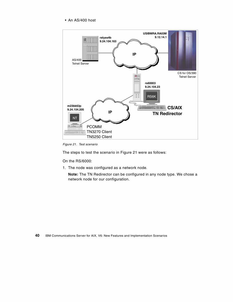
• An AS/400 host
Figure 21. Test scenario
The steps to test the scenario in Figure 21 were as follows:
On the RS/6000:
1. The node was configured as a network node.
Note: The TN Redirector can be configured in any node type. We chose anetwork node for our configuration.
NT
RS6K
PCOMMTN3270 ClientTN5250 Client
CS/AIXTN Redirector
CS for OS/390Telnet Server
AS/400Telnet Server
m23bk63p9.24.104.205
rs600039.24.104.23
USIBMRA.RA03M9.12.14.1ralyas4b
9.24.104.163
IP
IP
40 IBM Communications Server for AIX, V6: New Features and Implementation Scenarios
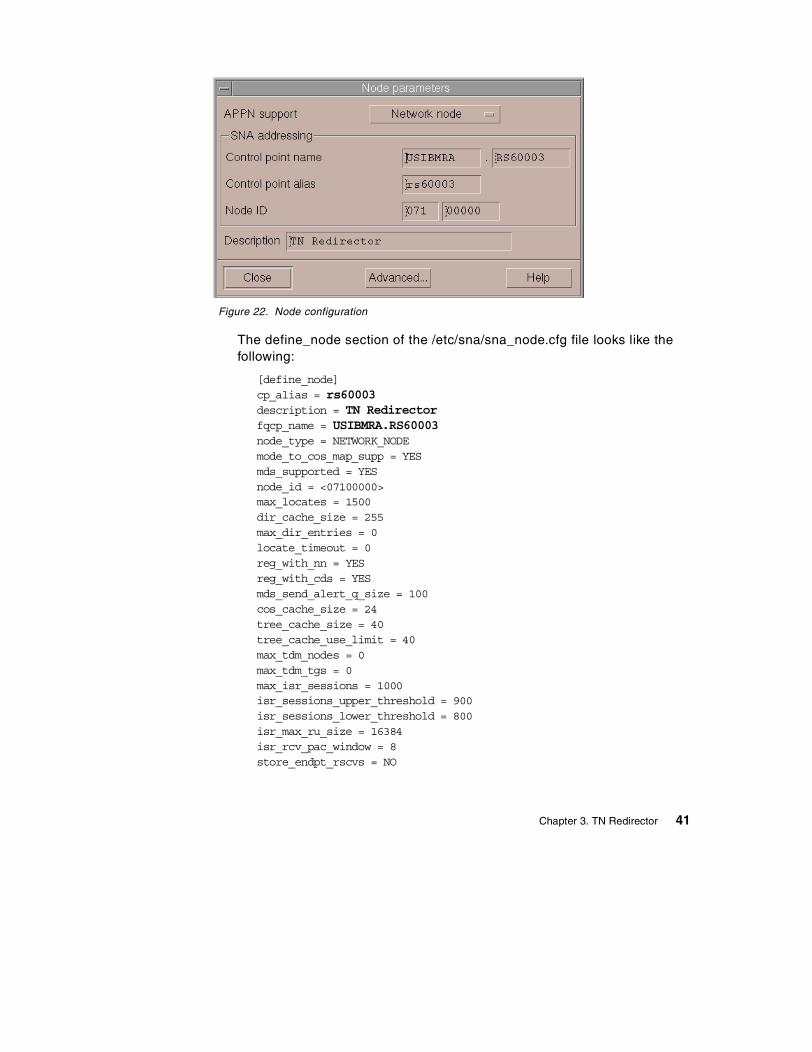
Figure 22. Node configuration
The define_node section of the /etc/sna/sna_node.cfg file looks like thefollowing:
[define_node]cp_alias = rs60003description = TN Redirectorfqcp_name = USIBMRA.RS60003node_type = NETWORK_NODEmode_to_cos_map_supp = YESmds_supported = YESnode_id = <07100000>max_locates = 1500dir_cache_size = 255max_dir_entries = 0locate_timeout = 0reg_with_nn = YESreg_with_cds = YESmds_send_alert_q_size = 100cos_cache_size = 24tree_cache_size = 40tree_cache_use_limit = 40max_tdm_nodes = 0max_tdm_tgs = 0max_isr_sessions = 1000isr_sessions_upper_threshold = 900isr_sessions_lower_threshold = 800isr_max_ru_size = 16384isr_rcv_pac_window = 8store_endpt_rscvs = NO
Chapter 3. TN Redirector 41
store_isr_rscvs = NOstore_dlur_rscvs = NOcos_table_version = VERSION_0_COS_TABLESsend_term_self = NOdisable_branch_awareness = NOcplu_syncpt_support = NOcplu_attributes = NONEdlur_support = YESpu_conc_support = YESnn_rar = 128max_ls_exception_events = 0ms_support = NORMALqueue_nmvts = YESptf_flags = NONE
2. The node was started.
3. Two TN Redirector access records were defined. One access record wasconfigured for connection to the CS for OS/390 host and the other foraccess to the AS/400. The configuration panel is shown in Figure 23 onpage 43.
42 IBM Communications Server for AIX, V6: New Features and Implementation Scenarios
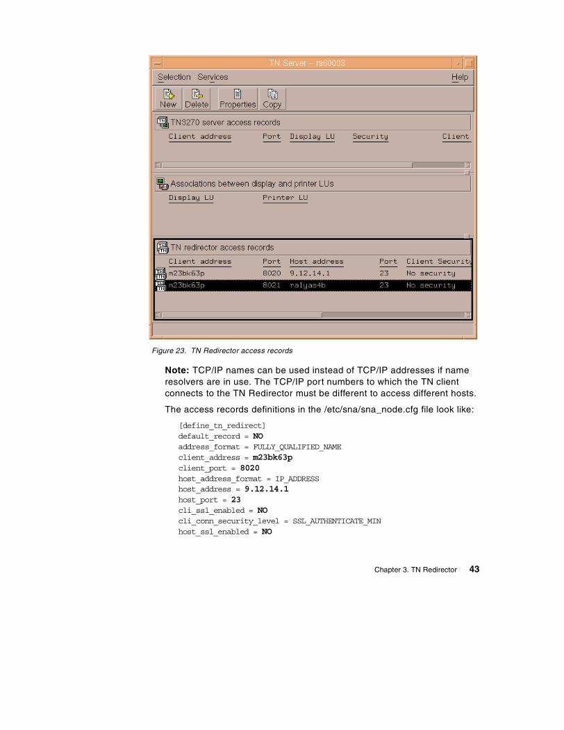
Figure 23. TN Redirector access records
Note: TCP/IP names can be used instead of TCP/IP addresses if nameresolvers are in use. The TCP/IP port numbers to which the TN clientconnects to the TN Redirector must be different to access different hosts.
The access records definitions in the /etc/sna/sna_node.cfg file look like:
[define_tn_redirect]default_record = NOaddress_format = FULLY_QUALIFIED_NAMEclient_address = m23bk63pclient_port = 8020host_address_format = IP_ADDRESShost_address = 9.12.14.1host_port = 23cli_ssl_enabled = NOcli_conn_security_level = SSL_AUTHENTICATE_MINhost_ssl_enabled = NO
Chapter 3. TN Redirector 43

serv_conn_security_level = SSL_AUTHENTICATE_MINdescription = TN3270 sessioncli_conn_cert_key_label = ““serv_conn_cert_key_label = ““
[define_tn_redirect]default_record = NOaddress_format = FULLY_QUALIFIED_NAMEclient_address = m23bk63pclient_port = 8021host_address_format = FULLY_QUALIFIED_NAMEhost_address = ralyas4bhost_port = 23cli_ssl_enabled = NOcli_conn_security_level = SSL_AUTHENTICATE_MINhost_ssl_enabled = NOserv_conn_security_level = SSL_AUTHENTICATE_MINdescription = TN5250 sessioncli_conn_cert_key_label = ““serv_conn_cert_key_label = ““
On the PC:
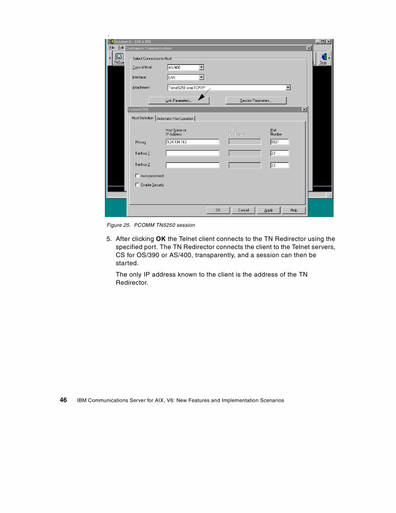
4. Using PCOMM (IBM Personal Communications software for Windows NT)we configured two Telnet sessions, one to the host CS for OS/390 and theother to the AS/400. From the session window click Communication ->Configure -> Link Parameters.
In both cases, Figure 24 on page 45 and Figure 25 on page 46, the LinkParameters consist of the hostname or IP address of the TN Redirector andthe port number to which the Telnet client connects to the TN Redirector.
44 IBM Communications Server for AIX, V6: New Features and Implementation Scenarios
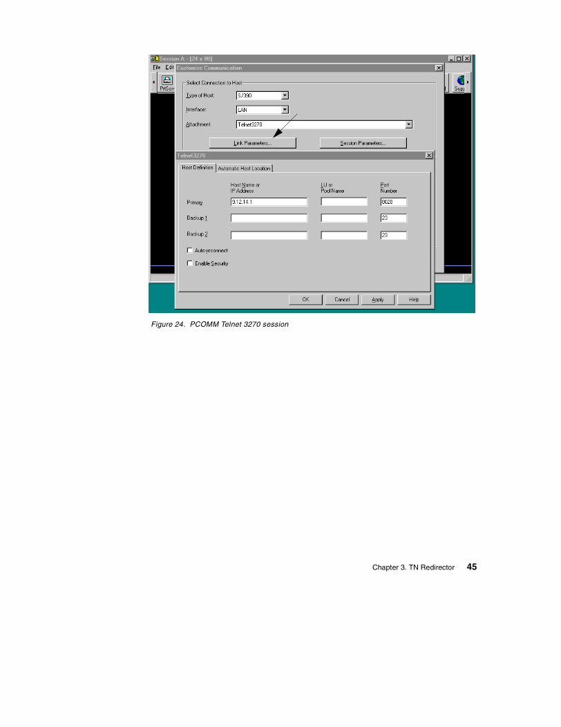
Figure 24. PCOMM Telnet 3270 session
Chapter 3. TN Redirector 45
.
Figure 25. PCOMM TN5250 session
5. After clicking OK the Telnet client connects to the TN Redirector using thespecified port. The TN Redirector connects the client to the Telnet servers,CS for OS/390 or AS/400, transparently, and a session can then bestarted.
The only IP address known to the client is the address of the TNRedirector.
46 IBM Communications Server for AIX, V6: New Features and Implementation Scenarios
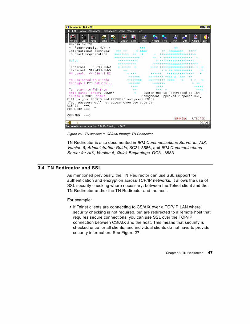
Figure 26. TN session to OS/390 through TN Redirector
TN Redirector is also documented in IBM Communications Server for AIX,Version 6, Administration Guide, SC31-8586, and IBM CommunicationsServer for AIX, Version 6, Quick Beginnings, GC31-8583.
3.4 TN Redirector and SSL
As mentioned previously, the TN Redirector can use SSL support forauthentication and encryption across TCP/IP networks. It allows the use ofSSL security checking where necessary: between the Telnet client and theTN Redirector and/or the TN Redirector and the host.
For example:
• If Telnet clients are connecting to CS/AIX over a TCP/IP LAN wheresecurity checking is not required, but are redirected to a remote host thatrequires secure connections, you can use SSL over the TCP/IPconnection between CS/AIX and the host. This means that security ischecked once for all clients, and individual clients do not have to providesecurity information. See Figure 27.
Chapter 3. TN Redirector 47
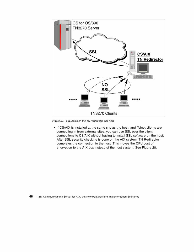
Figure 27. SSL between the TN Redirector and host
• If CS/AIX is installed at the same site as the host, and Telnet clients areconnecting in from external sites, you can use SSL over the clientconnections to CS/AIX without having to install SSL software on the host.After SSL security checking is done on the AIX system, TN Redirectorcompletes the connection to the host. This moves the CPU cost ofencryption to the AIX box instead of the host system. See Figure 28.
CS for OS/390TN3270 Server
TN3270 Clients
CS/AIX
CS/AIXTN Redirector
SSL
NOSSL
.... ....
48 IBM Communications Server for AIX, V6: New Features and Implementation Scenarios
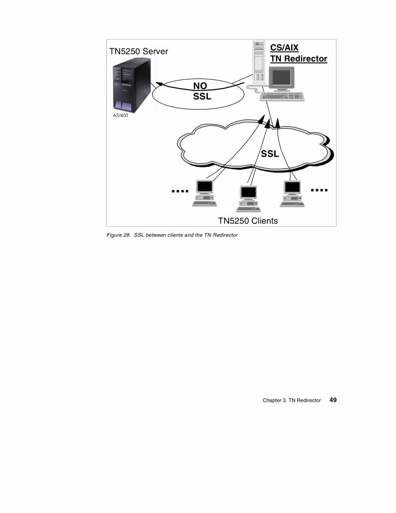
Figure 28. SSL between clients and the TN Redirector
TN5250 Clients
CS/AIX
CS/AIXTN Redirector
SSL
NOSSL
.... ....
TN5250 Server
Chapter 3. TN Redirector 49

50 IBM Communications Server for AIX, V6: New Features and Implementation Scenarios
Chapter 4. Service Location Protocol (SLP)
Service Location Protocol (SLP) specifies a method to provide dynamicdirectory services specifically for finding servers by attributes rather than byname or address. In so doing, SLP provides a standard method of allocatingservice requests among a set of servers with some level of workloadbalancing. SLP uses multicast services to locate SLP components andunicast services to communicate between components.
IBM Communication Server for AIX, V6.0 supports SLP providing servicelocation and server load balancing for CS/AIX TN3270 servers. In thischapter, we will discuss the new function of the IBM CS/AIX Service LocationProtocol and how to implement it in an Internet network environment.
4.1 Overview
As businesses expand the scope of their network resources by connectingcorporate LANs and WANs with TCP/IP-based intranets, TN3270E serversplay an increasingly important role in providing mainframe host connectivityto TCP/IP-based clients. Service Location Protocol (SLP) allows corporatein-house “intranet” environments using Internet standards, in conjunction withTN3270E servers and emulators, to provide fast, reliable and cost-effectiveload-balanced host sessions for end users.
4.1.1 Service location protocolService Location Protocol is a new Internet Engineering Task Force (IETF)proposed standard protocol that was designed to simplify the discovery anduse of network resources. In a corporate intranet, users need to accessservices and resources on the network. Often, it is not clear to the users whatuseful services are available to them. These resources could includeTN3270E servers, Web servers, printers, fax machines, file systems,databases, and any other future services that might become available. IBMCommunications Server for AIX, Version 6 supports SLP in conjunction withTN3270E servers and clients.
SLP is defined in Request for Comments (RFC) 2165. It is aservice-discovery method for TCP/IP-based communications, providing asimple and lightweight protocol for automatic advertisement and maintenanceof intranet services and minimizing the use of broadcast and multicast in thenetwork. SLP uses multicast, which targets a group of nodes, unlikebroadcast, which targets all nodes. The benefit of multicast is that it sendsone packet that all members of the group receive, but that only the intended
© Copyright IBM Corp. 2000 51
recipients read. A multicast packet is not isolated to a local segment; routescan forward it to whatever subnets are attached.
Without SLP, users find services by using the name of a network host (ahuman-readable text string) that is an alias for a network address. ServiceLocation Protocol eliminates the need for a user to know the name of anetwork host supporting a service. Service Location Protocol allows the userto bind a service description to the network address of the service.
SLP provides a dynamic configuration mechanism for applications in localarea networks. It is not a global resolution system for the entire Internet;rather it is intended to serve enterprise networks with shared services.Applications are modeled as clients that need to find servers attached to theenterprise network at a possibly distant location. For cases where there aremany different clients and/or services available, the protocol is adapted tomake use of nearby directory agents that offer a centralized repository foradvertised services.
4.1.2 SLP terminologySLP defines three types of agents as shown in Figure 29.
• User agent (UA):
Supports service query functions. It acquires/requests service informationfor user applications. The user agent retrieves service information from theservice agent or directory agents.
• Service agent (SA):
Service registration and service advertisement.
• Directory agent (DA):
Collects service information from service agents to provide a repository ofservice information in order to centralize it for efficient access by useragents. There can only be one DA present per given host.
52 IBM Communications Server for AIX, V6: New Features and Implementation Scenarios
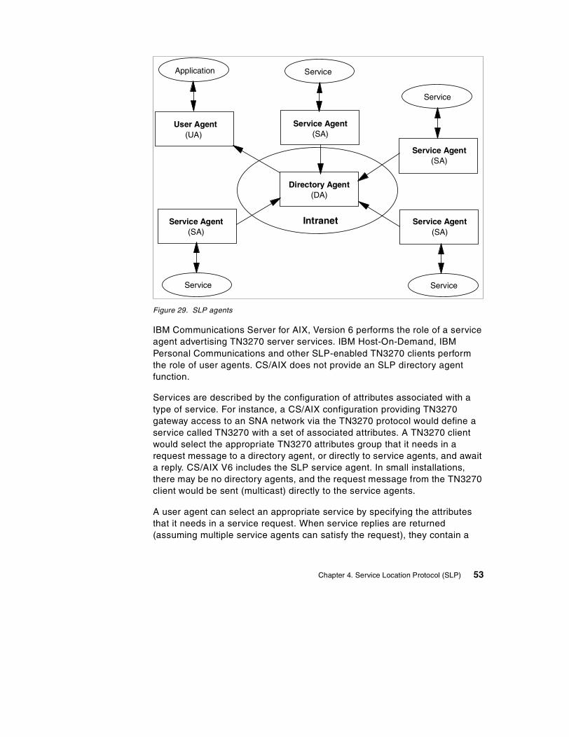
Figure 29. SLP agents
IBM Communications Server for AIX, Version 6 performs the role of a serviceagent advertising TN3270 server services. IBM Host-On-Demand, IBMPersonal Communications and other SLP-enabled TN3270 clients performthe role of user agents. CS/AIX does not provide an SLP directory agentfunction.
Services are described by the configuration of attributes associated with atype of service. For instance, a CS/AIX configuration providing TN3270gateway access to an SNA network via the TN3270 protocol would define aservice called TN3270 with a set of associated attributes. A TN3270 clientwould select the appropriate TN3270 attributes group that it needs in arequest message to a directory agent, or directly to service agents, and awaita reply. CS/AIX V6 includes the SLP service agent. In small installations,there may be no directory agents, and the request message from the TN3270client would be sent (multicast) directly to the service agents.
A user agent can select an appropriate service by specifying the attributesthat it needs in a service request. When service replies are returned(assuming multiple service agents can satisfy the request), they contain a
Directory Agent(DA)
User Agent(UA)
Service Agent(SA)
Application Service
Service
Service
Intranet
Service
Service Agent(SA)
Service Agent(SA)
Service Agent(SA)
Chapter 4. Service Location Protocol (SLP) 53
Uniform Resource Locator (URL) pointing to the service desired, and otherinformation, such as server load, needed by the user agent.
Following is additional terminology used when discussing SLP:
• Service
The service is a process or system (such as TN3270 server, Web server,and so on) providing a function or service to the network. The service itselfis accessed using a communication mechanism external to the ServiceLocation Protocol.
• Service Information
A collection of attributes and configuration information associated with asingle service. The service agents advertise service information for acollection of service instances.
• Site Network
All the hosts accessible within the agent’s multicast radius, which defaultsto a value appropriate for reaching all hosts within a site. If the site doesnot support multicast, the agent’s site network is restricted to a singlesubnet.
• Scope
A collection of services that make up a logical group.
4.1.3 SLP load balancingLoad balancing using SLP dynamically balances user agent sessions bydistributing them to the service agent (which supports the desired service)with the smallest load. TN3270 clients that support load balancing have theability to query participating SLP TN3270E servers and connect to the leastloaded service agent (for example, a CS/AIX TN3270 server gateway).
The SLP load balancing weight factor gives the administrator the ability tomodify or weight the load balancing measurement for each server. The factorcan be different for each server. The measurement can take into accountnumbers of active sessions, memory constraints and CPU constraints oneach server. The weight factor gives the administrator an element of control inthis calculation. The weighting factor is useful because:
• In some cases, there are other factors that may have an effect on serverload that are not taken into account by the server load algorithm, forexample, if the server is not dedicated to SNA gateway traffic only.
• If the server providing TN3270 services must coexist in a network withother TN server implementations using SLP for load balancing, the load
54 IBM Communications Server for AIX, V6: New Features and Implementation Scenarios
factor can be adjusted to compensate for differences between servermachines.
The weight factor allows the administrator to bias the load measurement onthat server either away from or towards selecting the server. The factor canbe turned on or off as well, causing it to be ignored in load calculations.
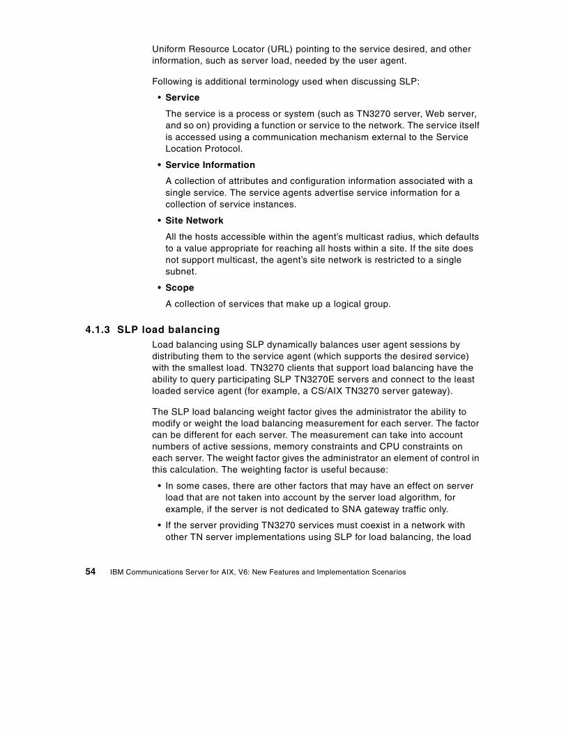
As shown in Figure 30, when a TN3270 client requests a session to the host,those servers that support TN3270 services respond with their current load.The least loaded TN3270 server will be chosen by the client to makeconnection to the host.
Figure 30. SLP load balancing
Note that both the TN3270 client and TN3270 server must support SLP andthe load balancing process.
4.1.4 SLP scopeSLP can reduce overall network traffic by using scopes to manage clientservice requests. A scope is essentially a grouping method used to organizeservers into named groups or pools. This is ideal for large networks with anumber of gateways or servers.
Scope can be looked at in two different ways:
SLPTN Server ALoad = 50
SLP
Multicast
TN3270 connection
SLPTN3270 Client
HOST
SNA APPNor 3270 LEN
IP
SLPTN Server CLoad = 30
SLPTN Server BLoad = 60
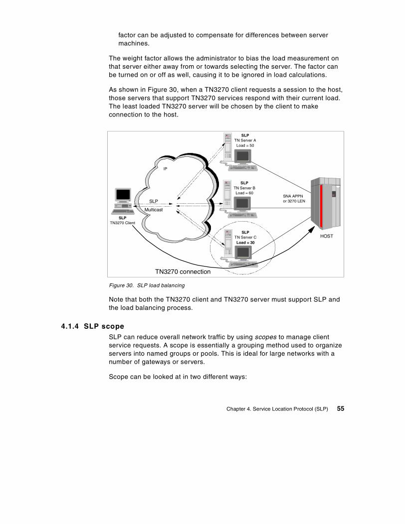
Chapter 4. Service Location Protocol (SLP) 55
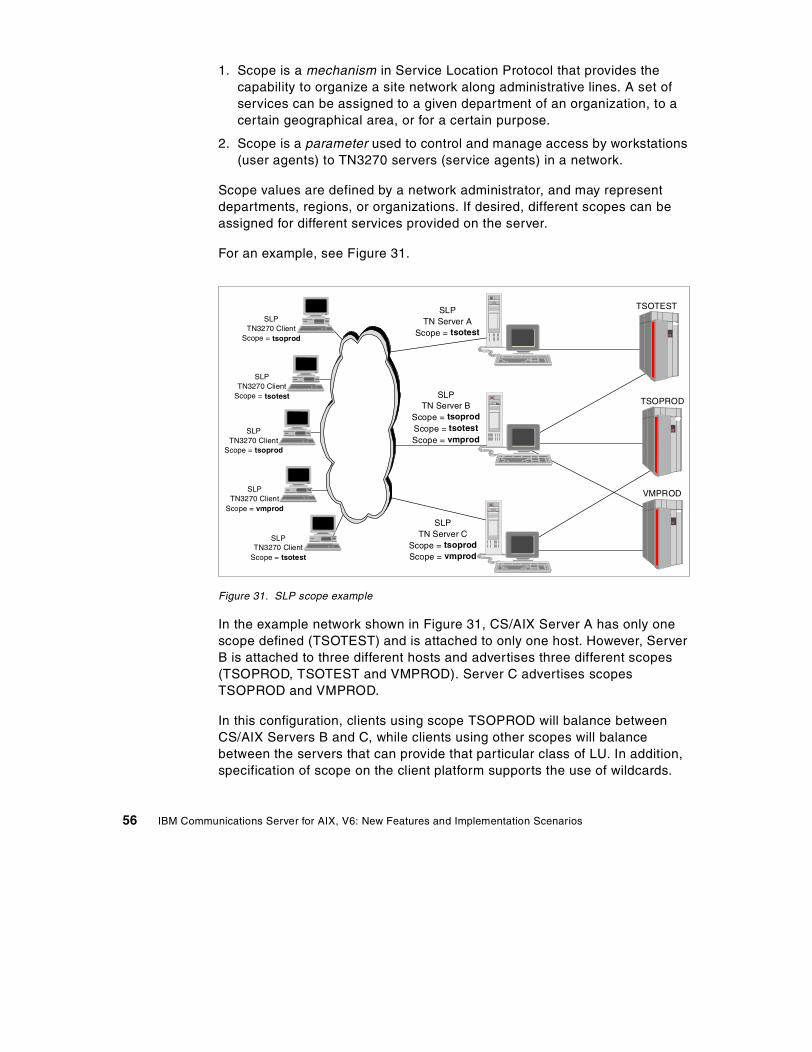
1. Scope is a mechanism in Service Location Protocol that provides thecapability to organize a site network along administrative lines. A set ofservices can be assigned to a given department of an organization, to acertain geographical area, or for a certain purpose.
2. Scope is a parameter used to control and manage access by workstations(user agents) to TN3270 servers (service agents) in a network.
Scope values are defined by a network administrator, and may representdepartments, regions, or organizations. If desired, different scopes can beassigned for different services provided on the server.
For an example, see Figure 31.
Figure 31. SLP scope example
In the example network shown in Figure 31, CS/AIX Server A has only onescope defined (TSOTEST) and is attached to only one host. However, ServerB is attached to three different hosts and advertises three different scopes(TSOPROD, TSOTEST and VMPROD). Server C advertises scopesTSOPROD and VMPROD.
In this configuration, clients using scope TSOPROD will balance betweenCS/AIX Servers B and C, while clients using other scopes will balancebetween the servers that can provide that particular class of LU. In addition,specification of scope on the client platform supports the use of wildcards.
SLPTN Server A
Scope = tsotest
SLPTN3270 Client
Scope = tsoprod
SLPTN Server B
Scope = tsoprodScope = tsotestScope = vmprod
SLPTN Server C
Scope = tsoprodScope = vmprod
TSOTEST
TSOPROD
VMPROD
SLPTN3270 Client
Scope = tsoprod
SLPTN3270 Client
Scope = tsotest
SLPTN3270 Client
Scope = vmprod
SLPTN3270 Client
Scope = tsotest
56 IBM Communications Server for AIX, V6: New Features and Implementation Scenarios

For example, a client that specifies a scope of TSO* can select betweenservers that advertise scopes of TSOTEST and TSOPROD.
4.2 SLP review
The basic operation in Service Location Protocol is that a client attempts todiscover the location of a service. In smaller installations, each service will beconfigured to respond individually to each client. In larger installations,services will register their services with one or more directory agents, andclients will contact the directory agent to fulfill requests for Service Locationinformation.
A large network can be divided and categorized by the use of scopes, so thatinformation about a TN server is advertised only to TN3270 clients anddirectory agents that have the same scope as the TN server. This allows youto control the range of service searches.
The following describes the operations a user agent would employ to findservices on the site’s network. The user agent needs no configuration tobegin network interaction. The user agent can acquire information toconstruct predicates that describe the services that match the user’s needs.The user agent may build on the information received in earlier networkrequests to find the service agents advertising service information.
A user agent will operate two ways:
1. If the user agent has already obtained the location of a directory agent, theuser agent will unicast a request to it in order to resolve a particularrequest. The directory agent will unicast a reply to the user agent. Theuser agent will retry a request to a directory agent until it gets a reply, so ifthe directory agent cannot service the request it must return an responsewith zero values, possibly with an error code set.
2. If the user agent does not have knowledge of a directory agent or if thereare no directory agents available on the site network, a second mode ofdiscovery may be used. The user agent multicasts a request to theservice-specific multicast address, to which the service it wishes to locatewill respond. All the service agents that are listening to this multicastaddress will respond, provided they can satisfy the user agent’s request.
A directory agent acts on behalf of many service agents. It acquiresinformation from them and acts as a single point of contact to supply thatinformation to user agents.
Chapter 4. Service Location Protocol (SLP) 57

The queries that a user agent multicasts to service agents (in an environmentwithout a directory agent) are the same as queries that the user agent mightunicast to a directory agent.
4.3 SLP support in CS/AIX
IBM Communications Server for AIX, Version 6 supports SLP serviceadvertisement and load balancing for TN3270 servers.
CS/AIX provides information about the server load by calculating thepercentage of available resources. For TN3270(E) sessions, the loadpercentage is the number of active application connections divided by thetotal number of LUs available.
Because SLP in CS/AIX provides services that are available for use by anyTN3270 client, it operates only if a default TN3270 access record has beendefined to allow access by any client. If an access record for a specific namedclients is defined and no default records are included, the TN server servicewill not advertise.
4.3.1 Configuring TN3270 server with SLPService Location Protocol support in CS/AIX is configured from the TN Serverpanel. Using xsnaadmin, from the initial node panel, select Services -> TNServer -> TN Server.
On the TN Server panel select Services -> TN3270 SLP Parameters.
See Figure 32.
58 IBM Communications Server for AIX, V6: New Features and Implementation Scenarios
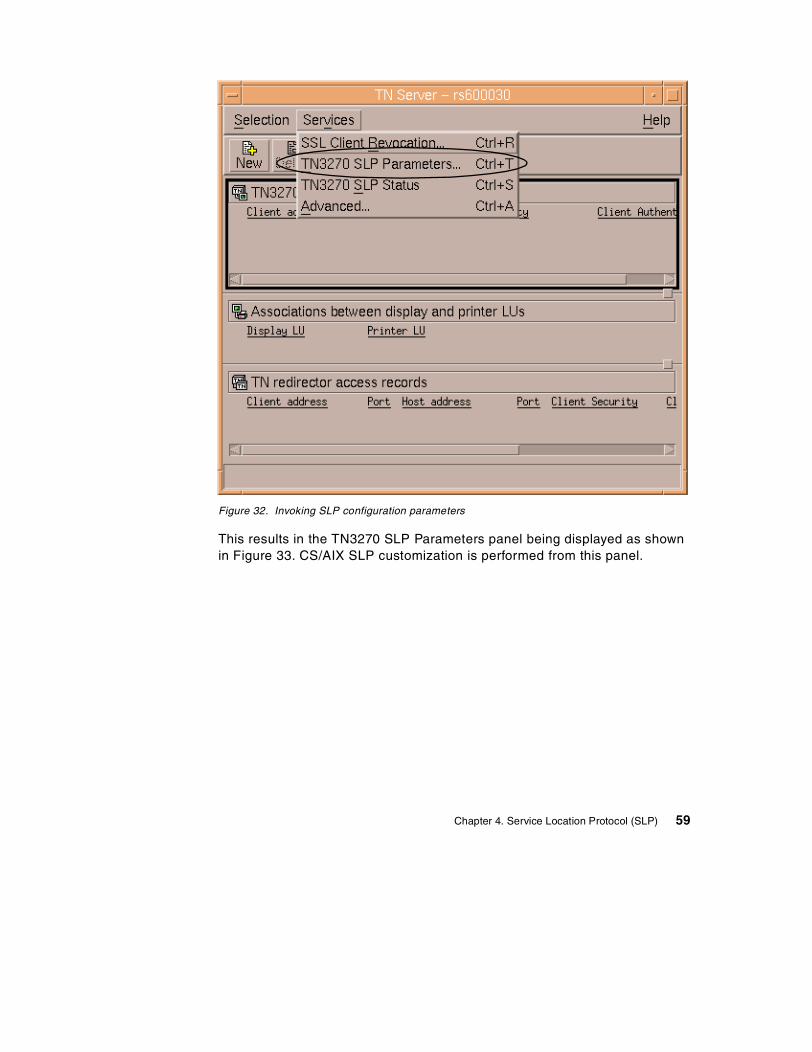
Figure 32. Invoking SLP configuration parameters
This results in the TN3270 SLP Parameters panel being displayed as shownin Figure 33. CS/AIX SLP customization is performed from this panel.
Chapter 4. Service Location Protocol (SLP) 59

Figure 33. Enable load balancing window
• Enable load balancing
This check box enables SLP load balancing to be started with the TN3270server.
• Load advertisement frequency
This specifies the frequency, in seconds, with which the TN server loadshould be determined.
• Load change threshold
This specifies the absolute change in load required to reregister the load.
• Load factor
This allows you to weight the calculated load to compensate fordifferences such as available memory or processor speed. Specifying anegative number decreases the calculated session load, and specifying apositive number increases the calculated session load. Hence, you canincrease the load factor to decrease the number of sessions the servermanages (and vice-versa). Enter an integer between -100 and 100.
60 IBM Communications Server for AIX, V6: New Features and Implementation Scenarios
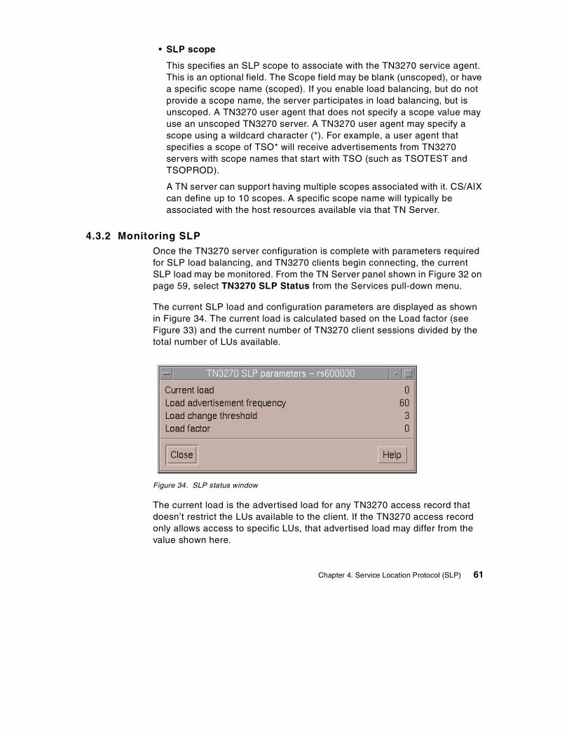
• SLP scope
This specifies an SLP scope to associate with the TN3270 service agent.This is an optional field. The Scope field may be blank (unscoped), or havea specific scope name (scoped). If you enable load balancing, but do notprovide a scope name, the server participates in load balancing, but isunscoped. A TN3270 user agent that does not specify a scope value mayuse an unscoped TN3270 server. A TN3270 user agent may specify ascope using a wildcard character (*). For example, a user agent thatspecifies a scope of TSO* will receive advertisements from TN3270servers with scope names that start with TSO (such as TSOTEST andTSOPROD).
A TN server can support having multiple scopes associated with it. CS/AIXcan define up to 10 scopes. A specific scope name will typically beassociated with the host resources available via that TN Server.
4.3.2 Monitoring SLPOnce the TN3270 server configuration is complete with parameters requiredfor SLP load balancing, and TN3270 clients begin connecting, the currentSLP load may be monitored. From the TN Server panel shown in Figure 32 onpage 59, select TN3270 SLP Status from the Services pull-down menu.
The current SLP load and configuration parameters are displayed as shownin Figure 34. The current load is calculated based on the Load factor (seeFigure 33) and the current number of TN3270 client sessions divided by thetotal number of LUs available.
Figure 34. SLP status window
The current load is the advertised load for any TN3270 access record thatdoesn’t restrict the LUs available to the client. If the TN3270 access recordonly allows access to specific LUs, that advertised load may differ from thevalue shown here.
Chapter 4. Service Location Protocol (SLP) 61

Note: When there are multiple SLP TN3270 service agents available tosatisfy SLP user agent requests, special consideration should be taken tocoordinate the load advertisement frequency values in all the service agents(see Figure 33 on page 60). If one of the service agents is configured with aload advertisement frequency that is much higher than the others (it does notrecalculate its load as often as the other agents), and client login activity ishigh, that service agent could accept an unduly larger proportion of the loginrequests than the other service agents. This is because the other serviceagents adjust their load more often and may reflect a higher load whenresponding to a user agent request. The service agent with the higher loadadvertisement frequency continues to advertise a lower load value eventhough it has accepted many more login requests than the other serviceagents.
4.4 Scenario
Figure 35 shows a sample network that we will use to step throughconfiguration of SLP support on CS/AIX.
Three RS/6000 machines running IBM Communications Server for AIX,Version 6 are configured with SLP-enabled TN3270 servers. A scope namedslp will be used to group the servers. LUs will be defined on each machine tosupport sessions from the TN3270 gateway to the host. At the same time,clients will use an SLP-enabled 3270 emulator (PCOMM for Windows NTV4.3) to connect to the host through the scoped TN3270 servers. From aclient’s point of view, there is no need to define any TN3270 server’s IPaddress (or alias) or port number to which clients try to connect.
We will also review the change in server load as clients log in to the host.
62 IBM Communications Server for AIX, V6: New Features and Implementation Scenarios
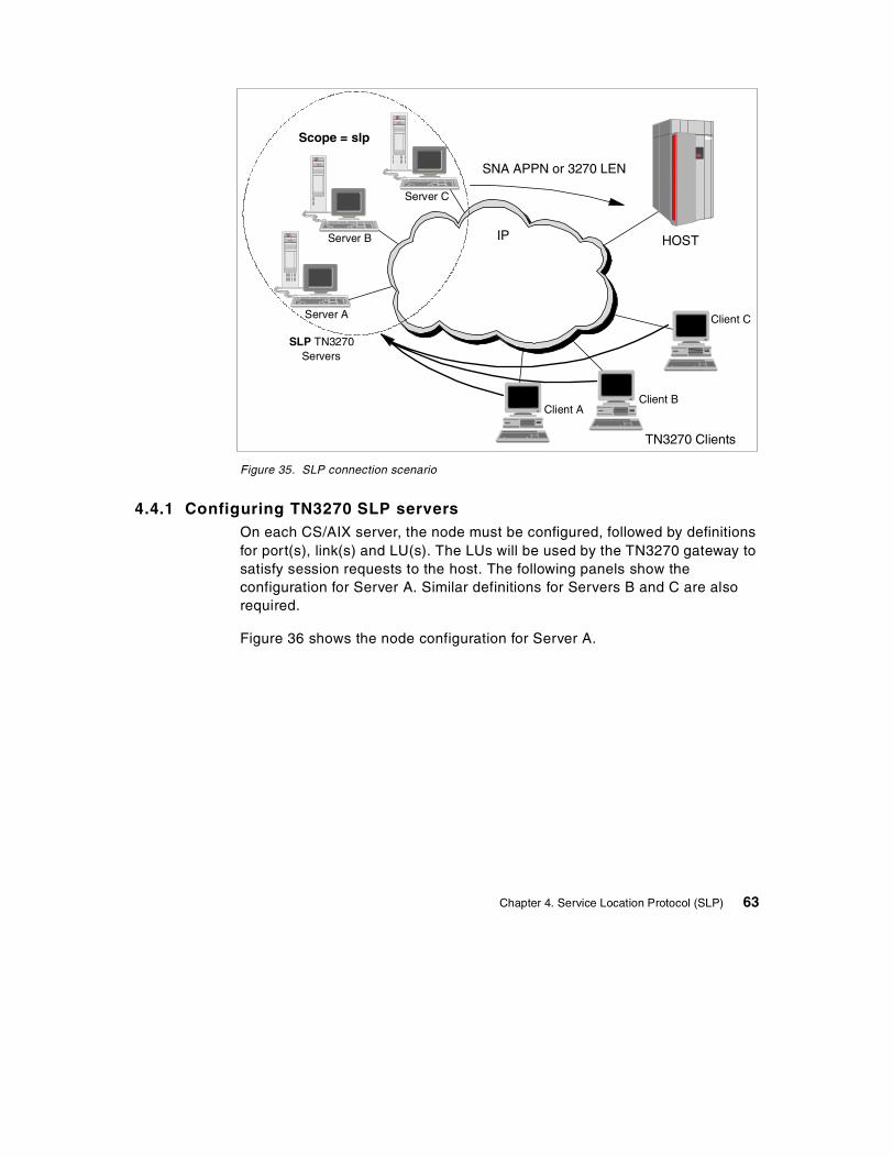
Figure 35. SLP connection scenario
4.4.1 Configuring TN3270 SLP serversOn each CS/AIX server, the node must be configured, followed by definitionsfor port(s), link(s) and LU(s). The LUs will be used by the TN3270 gateway tosatisfy session requests to the host. The following panels show theconfiguration for Server A. Similar definitions for Servers B and C are alsorequired.
Figure 36 shows the node configuration for Server A.
SLP TN3270Servers
TN3270 Clients
Client AClient B
Client CServer A
Server B
SNA APPN or 3270 LEN
IP HOST
Scope = slp
Server C
Chapter 4. Service Location Protocol (SLP) 63
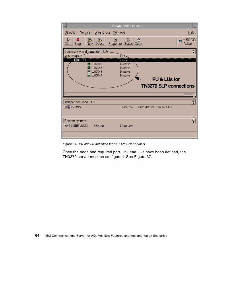
Figure 36. PU and LU definition for SLP TN3270 Server A
Once the node and required port, link and LUs have been defined, theTN3270 server must be configured. See Figure 37.
PU & LUs forTN3270 SLP connections
64 IBM Communications Server for AIX, V6: New Features and Implementation Scenarios
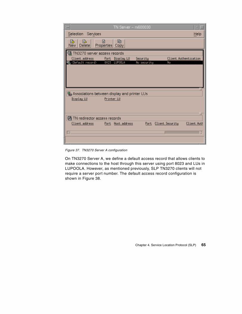
Figure 37. TN3270 Server A configuration
On TN3270 Server A, we define a default access record that allows clients tomake connections to the host through this server using port 8023 and LUs inLUPOOLA. However, as mentioned previously, SLP TN3270 clients will notrequire a server port number. The default access record configuration isshown in Figure 38.
Chapter 4. Service Location Protocol (SLP) 65
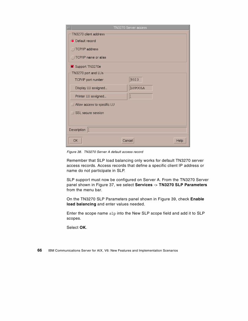
Figure 38. TN3270 Server A default access record
Remember that SLP load balancing only works for default TN3270 serveraccess records. Access records that define a specific client IP address orname do not participate in SLP.
SLP support must now be configured on Server A. From the TN3270 Serverpanel shown in Figure 37, we select Services -> TN3270 SLP Parametersfrom the menu bar.
On the TN3270 SLP Parameters panel shown in Figure 39, check Enableload balancing and enter values needed.
Enter the scope name slp into the New SLP scope field and add it to SLPscopes.
Select OK.
66 IBM Communications Server for AIX, V6: New Features and Implementation Scenarios
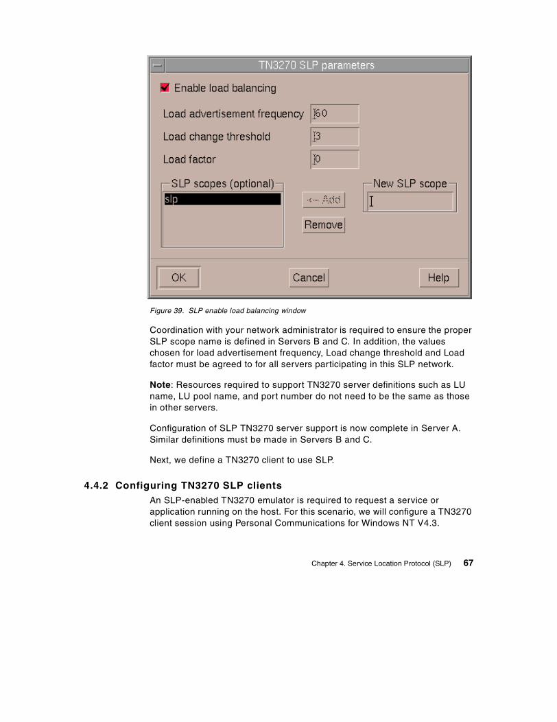
Figure 39. SLP enable load balancing window
Coordination with your network administrator is required to ensure the properSLP scope name is defined in Servers B and C. In addition, the valueschosen for load advertisement frequency, Load change threshold and Loadfactor must be agreed to for all servers participating in this SLP network.
Note: Resources required to support TN3270 server definitions such as LUname, LU pool name, and port number do not need to be the same as thosein other servers.
Configuration of SLP TN3270 server support is now complete in Server A.Similar definitions must be made in Servers B and C.
Next, we define a TN3270 client to use SLP.
4.4.2 Configuring TN3270 SLP clientsAn SLP-enabled TN3270 emulator is required to request a service orapplication running on the host. For this scenario, we will configure a TN3270client session using Personal Communications for Windows NT V4.3.
Chapter 4. Service Location Protocol (SLP) 67
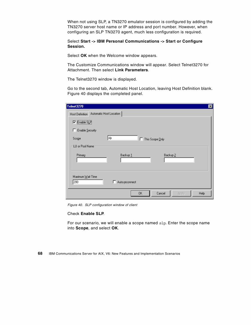
When not using SLP, a TN3270 emulator session is configured by adding theTN3270 server host name or IP address and port number. However, whenconfiguring an SLP TN3270 agent, much less configuration is required.
Select Start -> IBM Personal Communications -> Start or ConfigureSession.
Select OK when the Welcome window appears.
The Customize Communications window will appear. Select Telnet3270 forAttachment. Then select Link Parameters.
The Telnet3270 window is displayed.
Go to the second tab, Automatic Host Location, leaving Host Definition blank.Figure 40 displays the completed panel.
Figure 40. SLP configuration window of client
Check Enable SLP.
For our scenario, we will enable a scope named slp. Enter the scope nameinto Scope, and select OK.
68 IBM Communications Server for AIX, V6: New Features and Implementation Scenarios

An “*” (wildcard character) in the Scope field means that this SLP TN3270client user agent is unscoped, indicating that any SLP TN3270 server thatadvertises is acceptable to the client. Another example of using a wildcard ina scope name is to have one CS/AIX server use scope name SLP1 and asecond CS/AIX server use scope name SLP2. A client then may code ascope of slp* indicating that an advertisement from any TN3270 server witha scope starting with slp is acceptable.
If a server is not found for the specified scope, or if the scope is not definedon any server, SLP returns an unscoped server (if one is available), unlessyou check This-Scope-Only. If you check This-Scope-Only and no server isfound within the specified scope, the session will not connect.
If you want your session to use SSL security in addition to SLP loadbalancing, check Enable Security and follow the steps required to supportsecurity. Remember that the servers must also support SSL for securesessions to be established. For more information, refer to Chapter 2, “SecureSockets Layer support” on page 9.
Notice that you may also select a specific LU or Pool Name. If you havemultiple default TN3270 access records defined in your CS/AIX TN3270service agents, each with their own LU pool or specific LU, you may specifythat pool name or LU here to ensure you are connected to the correct LU.The TN3270 server port number is not required.
4.4.3 Connecting to TN3270 SLP serversIn this scenario, as mentioned in beginning part of this section, there arethree TN3270 SLP servers and three clients that request TN3270 sessions toservers. Client session requests are balanced between the three servers thatare available with their scope definition.
4.4.3.1 First session request from Client AClient A begins by requesting a host session. See Figure 41.
Chapter 4. Service Location Protocol (SLP) 69
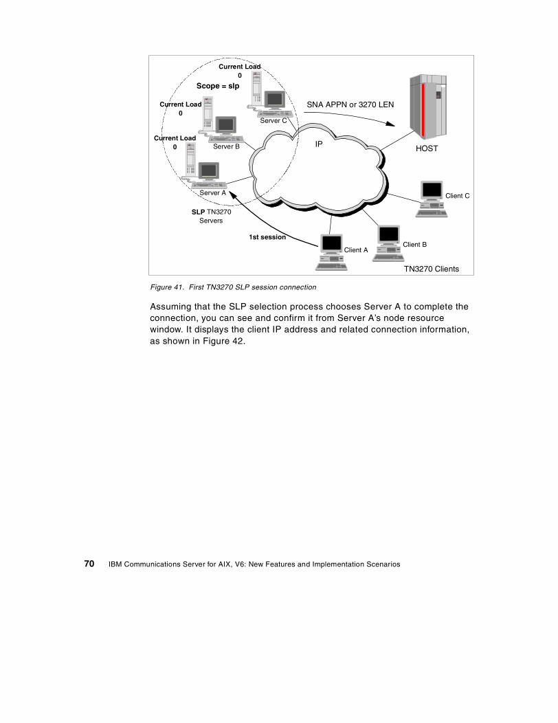
Figure 41. First TN3270 SLP session connection
Assuming that the SLP selection process chooses Server A to complete theconnection, you can see and confirm it from Server A’s node resourcewindow. It displays the client IP address and related connection information,as shown in Figure 42.
SLP TN3270Servers
TN3270 Clients
Client AClient B
Client CServer A
Server B
SNA APPN or 3270 LEN
IP HOST
Scope = slp
Server C
Current Load0
1st session
Current Load0
Current Load0
70 IBM Communications Server for AIX, V6: New Features and Implementation Scenarios
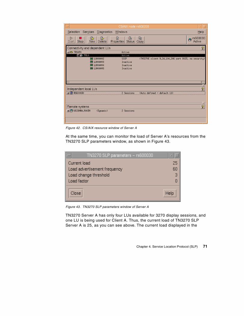
Figure 42. CS/AIX resource window of Server A
At the same time, you can monitor the load of Server A’s resources from theTN3270 SLP parameters window, as shown in Figure 43.
Figure 43. TN3270 SLP parameters window of Server A
TN3270 Server A has only four LUs available for 3270 display sessions, andone LU is being used for Client A. Thus, the current load of TN3270 SLPServer A is 25, as you can see above. The current load displayed in the
Chapter 4. Service Location Protocol (SLP) 71
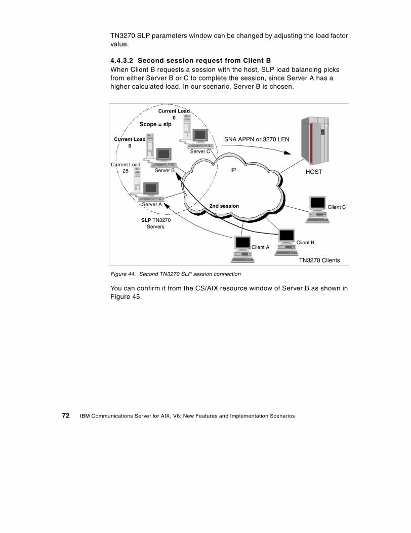
TN3270 SLP parameters window can be changed by adjusting the load factorvalue.
4.4.3.2 Second session request from Client BWhen Client B requests a session with the host, SLP load balancing picksfrom either Server B or C to complete the session, since Server A has ahigher calculated load. In our scenario, Server B is chosen.
Figure 44. Second TN3270 SLP session connection
You can confirm it from the CS/AIX resource window of Server B as shown inFigure 45.
SLP TN3270Servers
TN3270 Clients
Client AClient B
Client CServer A
Server B
SNA APPN or 3270 LEN
IP HOST
Server C
2nd session
Scope = slp
Current Load25
Current Load0
Current Load0
72 IBM Communications Server for AIX, V6: New Features and Implementation Scenarios
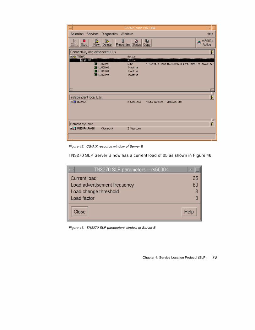
Figure 45. CS/AIX resource window of Server B
TN3270 SLP Server B now has a current load of 25 as shown in Figure 46.
Figure 46. TN3270 SLP parameters window of Server B
Chapter 4. Service Location Protocol (SLP) 73
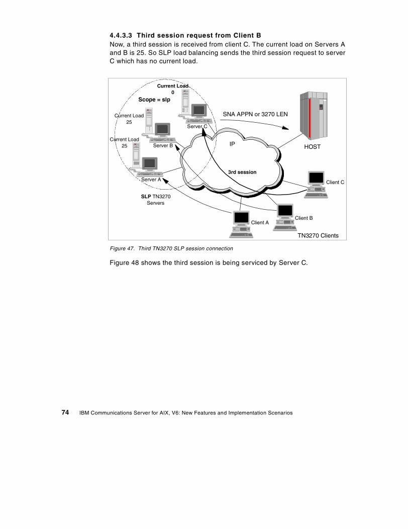
4.4.3.3 Third session request from Client BNow, a third session is received from client C. The current load on Servers Aand B is 25. So SLP load balancing sends the third session request to serverC which has no current load.
Figure 47. Third TN3270 SLP session connection
Figure 48 shows the third session is being serviced by Server C.
SLP TN3270Servers
TN3270 Clients
Client AClient B
Client CServer A
Server B
SNA APPN or 3270 LEN
IP HOST
Server C
3rd session
Current Load25
Current Load0
Current Load25
Scope = slp
74 IBM Communications Server for AIX, V6: New Features and Implementation Scenarios
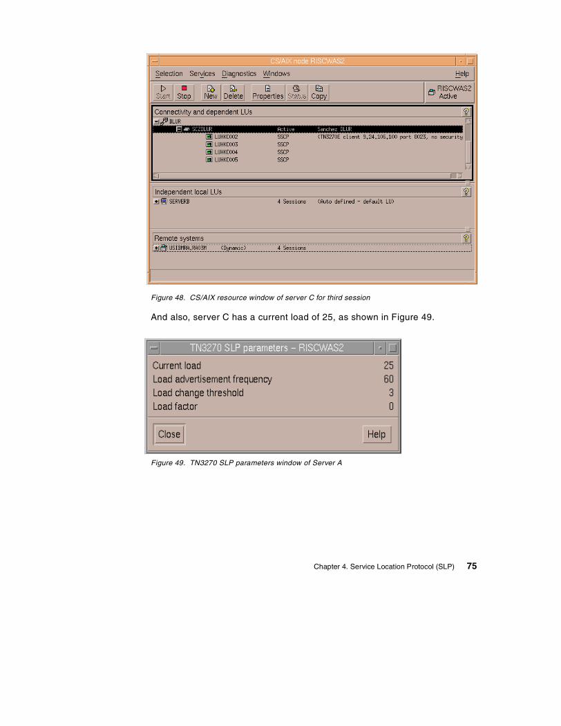
Figure 48. CS/AIX resource window of server C for third session
And also, server C has a current load of 25, as shown in Figure 49.
Figure 49. TN3270 SLP parameters window of Server A
Chapter 4. Service Location Protocol (SLP) 75

76 IBM Communications Server for AIX, V6: New Features and Implementation Scenarios
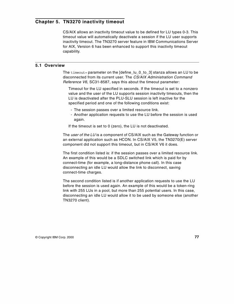
Chapter 5. TN3270 inactivity timeout
CS/AIX allows an inactivity timeout value to be defined for LU types 0-3. Thistimeout value will automatically deactivate a session if the LU user supportsinactivity timeout. The TN3270 server feature in IBM Communications Serverfor AIX, Version 6 has been enhanced to support this inactivity timeoutcapability.
5.1 Overview
The timeout= parameter on the [define_lu_0_to_3] stanza allows an LU to bedisconnected from its current user. The CS/AIX Administration CommandReference V6, SC31-8587, says this about the timeout parameter:
Timeout for the LU specified in seconds. If the timeout is set to a nonzerovalue and the user of the LU supports session inactivity timeouts, then theLU is deactivated after the PLU-SLU session is left inactive for thespecified period and one of the following conditions exist:
- The session passes over a limited resource link.- Another application requests to use the LU before the session is used
again.
If the timeout is set to 0 (zero), the LU is not deactivated.
The user of the LU is a component of CS/AIX such as the Gateway function oran external application such as HCON. In CS/AIX V5, the TN3270(E) servercomponent did not support this timeout, but in CS/AIX V6 it does.
The first condition listed is: if the session passes over a limited resource link.An example of this would be a SDLC switched link which is paid for byconnect-time (for example, a long-distance phone call). In this casedisconnecting an idle LU would allow the link to disconnect, savingconnect-time charges.
The second condition listed is if another application requests to use the LUbefore the session is used again. An example of this would be a token-ringlink with 255 LUs in a pool, but more than 255 potential users. In this case,disconnecting an idle LU would allow it to be used by someone else (anotherTN3270 client).
© Copyright IBM Corp. 2000 77
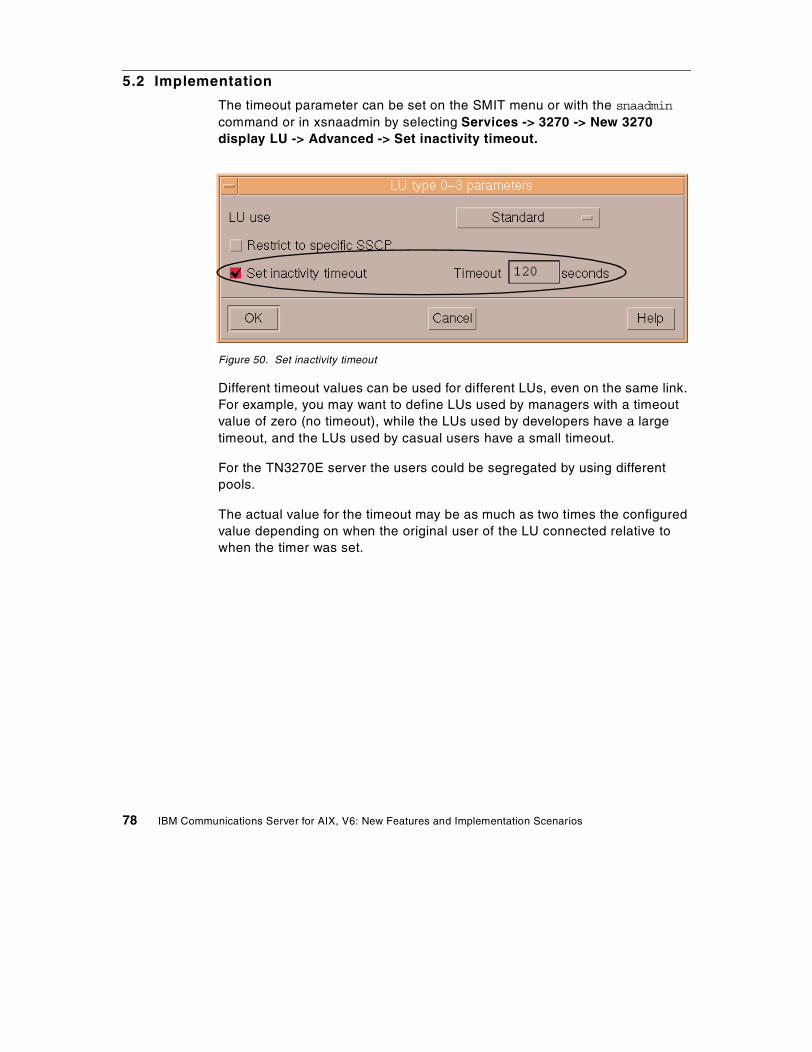
5.2 Implementation
The timeout parameter can be set on the SMIT menu or with the snaadmincommand or in xsnaadmin by selecting Services -> 3270 -> New 3270display LU -> Advanced -> Set inactivity timeout.
Figure 50. Set inactivity timeout
Different timeout values can be used for different LUs, even on the same link.For example, you may want to define LUs used by managers with a timeoutvalue of zero (no timeout), while the LUs used by developers have a largetimeout, and the LUs used by casual users have a small timeout.
For the TN3270E server the users could be segregated by using differentpools.
The actual value for the timeout may be as much as two times the configuredvalue depending on when the original user of the LU connected relative towhen the timer was set.
78 IBM Communications Server for AIX, V6: New Features and Implementation Scenarios

Part 3. SNA networking
© Copyright IBM Corp. 2000 79

80 IBM Communications Server for AIX, V6: New Features and Implementation Scenarios
Chapter 6. Enterprise Extender
This chapter describes the functionality of Enterprise Extender (EE), gives anoverview of High-Performance Routing (HPR), and discusses theimplementation of Enterprise Extender in CS/AIX. An example scenarioillustrates the use of HPR over IP to support SNA applications.
Enterprise Extender is also referred to as High Performance Routing over IP(HPR/IP). Throughout this chapter, Enterprise Extender will be referred to asEE and HPR/IP.
6.1 Overview
Enterprise Extender (or HPR/IP) provides High-Performance Routing (HPR)functionality over IP connections to support SNA applications connected overan IP network.
SNA applications are designed to use SNA protocols to communicate overSNA networks with other SNA applications. When installed in a TCP/IPnetwork using Enterprise Extender, SNA applications continue tocommunicate. The Enterprise Extender function provides a mechanism fortransporting SNA protocols over an IP network using the UDP protocol.Unlike AnyNet, Enterprise Extender provides APPN High-PerformanceRouting functionality, giving applications the benefits of both APPN and IPconnectivity.
Enterprise Extender in CS/AIX is implemented simply as a newcommunications link. To connect two SNA applications over IP, you define anEnterprise Extender link in the same way as for any other link type such asSDLC or Ethernet. This new DLC allows you to take advantage of APPN/HPRfunctions in the IP environment.
Note that Enterprise Extender (HPR/IP) links support independent LU6.2sessions. Dependent LUs are supported using DLUR over the EE link.
An example of a node configured with one explicit HPR/IP link to a NN isshown in Figure 51 on page 82.
© Copyright IBM Corp. 2000 81
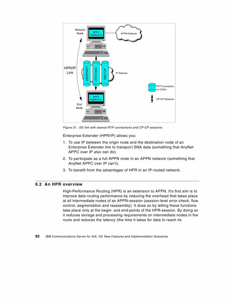
Figure 51. EE link with several RTP connections and CP-CP sessions
Enterprise Extender (HPR/IP) allows you:
1. To use IP between the origin node and the destination node of anEnterprise Extender link to transport SNA data (something that AnyNetAPPC over IP also can do).
2. To participate as a full APPN node in an APPN network (something thatAnyNet APPC over IP can’t).
3. To benefit from the advantages of HPR in an IP-routed network.
6.2 An HPR overview
High-Performance Routing (HPR) is an extension to APPN. It’s first aim is toimprove data routing performance by reducing the overhead that takes placeat all intermediate nodes of an APPN-session (session-level error check, flowcontrol, segmentation and reassembly). It does so by letting these functionstake place only at the begin- and end-points of the HPR-session. By doing soit reduces storage and processing requirements on intermediate nodes in theroute and reduces the latency (the time it takes for data to reach its
APPCApplication
APPCApplication APPN Network
IP Network
NetworkNode
EndNode
#IN
TE
RA
CT
CP
SV
CM
G
RS
ET
UPHPR/IP
Link
RTP Connectionfor COSx
CP-CP Sessions
82 IBM Communications Server for AIX, V6: New Features and Implementation Scenarios
destination) of the network. While in APPN, all NNs over which a sessiontraverses play an equally important role in error checking and recovery, inHPR the begin- and end-node are the only nodes responsible for thischecking, flow control and, if necessary, reassembly and segmentation. Thismeans that CPU and memory needs of intermediate nodes are less, but thatCPU and memory needs of the end-nodes is more. In a 1-hop (2 node) HPRenvironment, you get none of the advantages but you pay all the costs ofHPR, which means throughput is likely to be less than non-HPR.
A second aim of HPR is to allow for non-disruptive path switch if a link ornode in the path becomes unavailable. While in APPN a session has to followa route which has been determined at the session setup, in an HPR network,the LU-LU sessions flow within RTP connections (which can be thought of aspipes) which makes the underlying route (succession of NNs) invisible.
HPR’s main components by which these aims can be accomplished are:
• Rapid Transport Protocol (RTP)
• Automatic Network Routing (ANR)
• Adaptive Rate-Based (ARB) flow/congestion control. ARB is actually partof RTP.
6.2.1 Rapid Transport Protocol (RTP)Rapid Transport Protocol (RTP) is a connection-oriented, full-duplex protocoldesigned to transport SNA session traffic in high-speed networks. RTPprovides reliability (error recovery via selective retransmission), in-orderdelivery (a first-in-first-out service provided by resequencing data that arrivesout of order), message segmentation and reassembly, ARB flow congestioncontrol and automatic path-switching without disrupting sessions. BecauseRTP provides these functions on an end-to-end basis, it eliminates the needfor these functions to be implemented on the link level along the path of theconnection. The result is improved overall performance for HPR.
The physical path used by the RTP connection satisfies the Class Of Service(COS) associated with the sessions routed over it. Traffic from many sessionsrequesting the same COS can be routed over a single RTP connection. RTPconnections are used to:
• Transport CP-CP session traffic
• Transport LU-LU session traffic
• Carry route setup requests required to establish LU-LU sessions over aseries of RTP connections
Chapter 6. Enterprise Extender 83
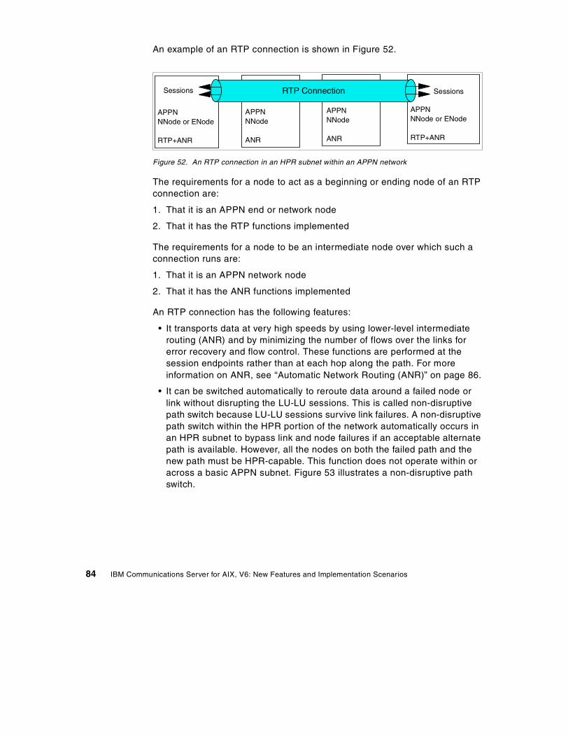
An example of an RTP connection is shown in Figure 52.
Figure 52. An RTP connection in an HPR subnet within an APPN network
The requirements for a node to act as a beginning or ending node of an RTPconnection are:
1. That it is an APPN end or network node
2. That it has the RTP functions implemented
The requirements for a node to be an intermediate node over which such aconnection runs are:
1. That it is an APPN network node
2. That it has the ANR functions implemented
An RTP connection has the following features:
• It transports data at very high speeds by using lower-level intermediaterouting (ANR) and by minimizing the number of flows over the links forerror recovery and flow control. These functions are performed at thesession endpoints rather than at each hop along the path. For moreinformation on ANR, see “Automatic Network Routing (ANR)” on page 86.
• It can be switched automatically to reroute data around a failed node orlink without disrupting the LU-LU sessions. This is called non-disruptivepath switch because LU-LU sessions survive link failures. A non-disruptivepath switch within the HPR portion of the network automatically occurs inan HPR subnet to bypass link and node failures if an acceptable alternatepath is available. However, all the nodes on both the failed path and thenew path must be HPR-capable. This function does not operate within oracross a basic APPN subnet. Figure 53 illustrates a non-disruptive pathswitch.
APPNNNode
ANR
APPNNNode
ANR
APPNNNode or ENode
RTP+ANR
APPNNNode or ENode
RTP+ANR
SessionsSessions RTP Connection
84 IBM Communications Server for AIX, V6: New Features and Implementation Scenarios
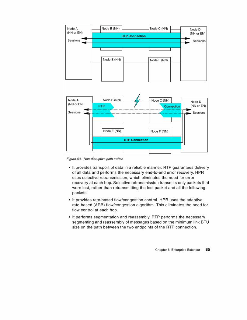
Figure 53. Non-disruptive path switch
• It provides transport of data in a reliable manner. RTP guarantees deliveryof all data and performs the necessary end-to-end error recovery. HPRuses selective retransmission, which eliminates the need for errorrecovery at each hop. Selective retransmission transmits only packets thatwere lost, rather than retransmitting the lost packet and all the followingpackets.
• It provides rate-based flow/congestion control. HPR uses the adaptiverate-based (ARB) flow/congestion algorithm. This eliminates the need forflow control at each hop.
• It performs segmentation and reassembly. RTP performs the necessarysegmenting and reassembly of messages based on the minimum link BTUsize on the path between the two endpoints of the RTP connection.
RTP ConnectionSessions Sessions
Node A(NN or EN)
Node B (NN) Node C (NN) Node D(NN or EN)
Node E (NN) Node F (NN)
Sessions Sessions
Node A(NN or EN)
Node B (NN) Node C (NN) Node D(NN or EN)
Node E (NN) Node F (NN)
RTP Connection
RTP Connection
RTP Connection
Chapter 6. Enterprise Extender 85
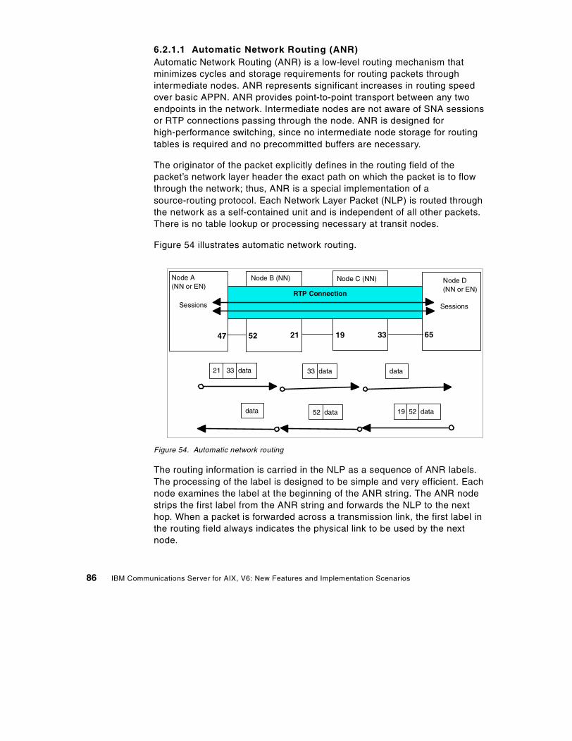
6.2.1.1 Automatic Network Routing (ANR)Automatic Network Routing (ANR) is a low-level routing mechanism thatminimizes cycles and storage requirements for routing packets throughintermediate nodes. ANR represents significant increases in routing speedover basic APPN. ANR provides point-to-point transport between any twoendpoints in the network. Intermediate nodes are not aware of SNA sessionsor RTP connections passing through the node. ANR is designed forhigh-performance switching, since no intermediate node storage for routingtables is required and no precommitted buffers are necessary.
The originator of the packet explicitly defines in the routing field of thepacket’s network layer header the exact path on which the packet is to flowthrough the network; thus, ANR is a special implementation of asource-routing protocol. Each Network Layer Packet (NLP) is routed throughthe network as a self-contained unit and is independent of all other packets.There is no table lookup or processing necessary at transit nodes.
Figure 54 illustrates automatic network routing.
Figure 54. Automatic network routing
The routing information is carried in the NLP as a sequence of ANR labels.The processing of the label is designed to be simple and very efficient. Eachnode examines the label at the beginning of the ANR string. The ANR nodestrips the first label from the ANR string and forwards the NLP to the nexthop. When a packet is forwarded across a transmission link, the first label inthe routing field always indicates the physical link to be used by the nextnode.
RTP Connection
Sessions Sessions
Node A(NN or EN)
Node B (NN) Node C (NN) Node D(NN or EN)
47 52 21 19 33 65
21 33 data 33 data data
19 52 data52 datadata
86 IBM Communications Server for AIX, V6: New Features and Implementation Scenarios
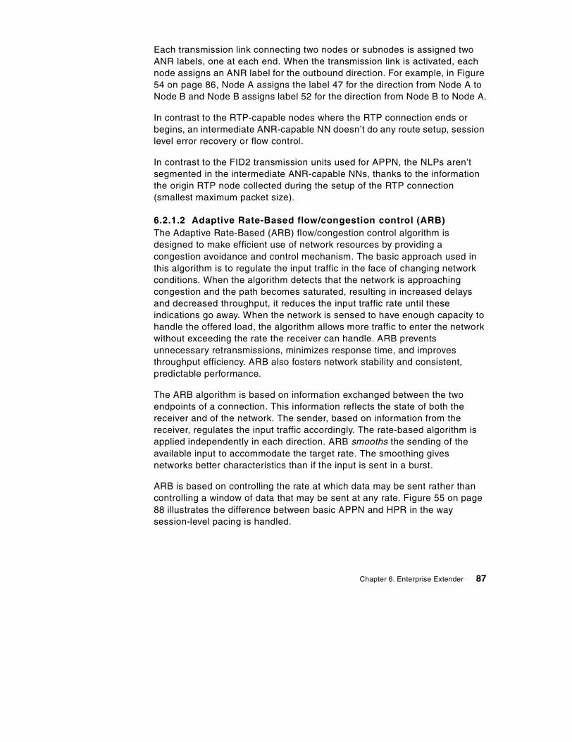
Each transmission link connecting two nodes or subnodes is assigned twoANR labels, one at each end. When the transmission link is activated, eachnode assigns an ANR label for the outbound direction. For example, in Figure54 on page 86, Node A assigns the label 47 for the direction from Node A toNode B and Node B assigns label 52 for the direction from Node B to Node A.
In contrast to the RTP-capable nodes where the RTP connection ends orbegins, an intermediate ANR-capable NN doesn’t do any route setup, sessionlevel error recovery or flow control.
In contrast to the FID2 transmission units used for APPN, the NLPs aren’tsegmented in the intermediate ANR-capable NNs, thanks to the informationthe origin RTP node collected during the setup of the RTP connection(smallest maximum packet size).
6.2.1.2 Adaptive Rate-Based flow/congestion control (ARB)The Adaptive Rate-Based (ARB) flow/congestion control algorithm isdesigned to make efficient use of network resources by providing acongestion avoidance and control mechanism. The basic approach used inthis algorithm is to regulate the input traffic in the face of changing networkconditions. When the algorithm detects that the network is approachingcongestion and the path becomes saturated, resulting in increased delaysand decreased throughput, it reduces the input traffic rate until theseindications go away. When the network is sensed to have enough capacity tohandle the offered load, the algorithm allows more traffic to enter the networkwithout exceeding the rate the receiver can handle. ARB preventsunnecessary retransmissions, minimizes response time, and improvesthroughput efficiency. ARB also fosters network stability and consistent,predictable performance.
The ARB algorithm is based on information exchanged between the twoendpoints of a connection. This information reflects the state of both thereceiver and of the network. The sender, based on information from thereceiver, regulates the input traffic accordingly. The rate-based algorithm isapplied independently in each direction. ARB smooths the sending of theavailable input to accommodate the target rate. The smoothing givesnetworks better characteristics than if the input is sent in a burst.
ARB is based on controlling the rate at which data may be sent rather thancontrolling a window of data that may be sent at any rate. Figure 55 on page88 illustrates the difference between basic APPN and HPR in the waysession-level pacing is handled.
Chapter 6. Enterprise Extender 87
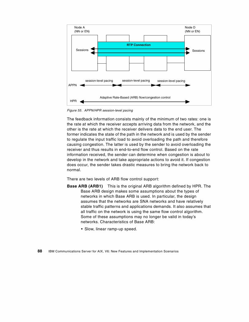
Figure 55. APPN/HPR session-level pacing
The feedback information consists mainly of the minimum of two rates: one isthe rate at which the receiver accepts arriving data from the network, and theother is the rate at which the receiver delivers data to the end user. Theformer indicates the state of the path in the network and is used by the senderto regulate the input traffic load to avoid overloading the path and thereforecausing congestion. The latter is used by the sender to avoid overloading thereceiver and thus results in end-to-end flow control. Based on the rateinformation received, the sender can determine when congestion is about todevelop in the network and take appropriate actions to avoid it. If congestiondoes occur, the sender takes drastic measures to bring the network back tonormal.
There are two levels of ARB flow control support:
Base ARB (ARB1) This is the original ARB algorithm defined by HPR. TheBase ARB design makes some assumptions about the types ofnetworks in which Base ARB is used. In particular, the designassumes that the networks are SNA networks and have relativelystable traffic patterns and applications demands. It also assumes thatall traffic on the network is using the same flow control algorithm.Some of these assumptions may no longer be valid in today’snetworks. Characteristics of Base ARB:
• Slow, linear ramp-up speed.
RTP Connection
Sessions Sessions
Node A(NN or EN)
Node D(NN or EN)
APPN
session-level pacing session-level pacing session-level pacing
HPRAdaptive Rate-Based (ARB) flow/congestion control
88 IBM Communications Server for AIX, V6: New Features and Implementation Scenarios
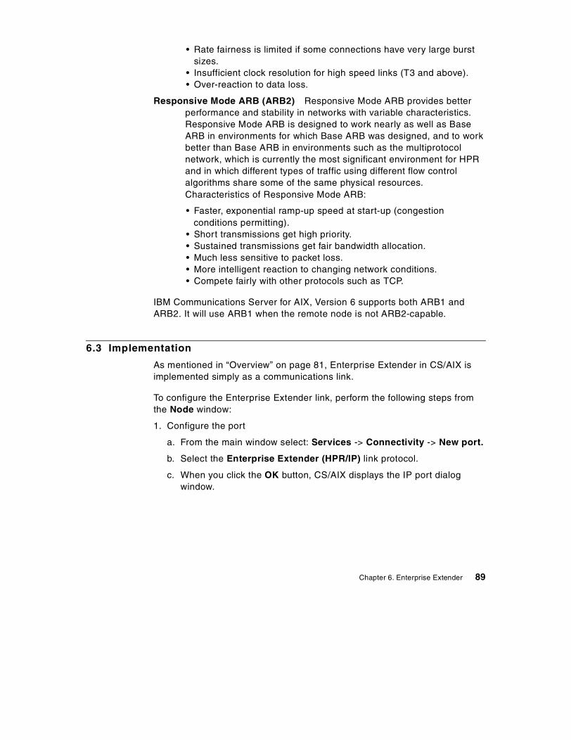
• Rate fairness is limited if some connections have very large burstsizes.
• Insufficient clock resolution for high speed links (T3 and above).• Over-reaction to data loss.
Responsive Mode ARB (ARB2) Responsive Mode ARB provides betterperformance and stability in networks with variable characteristics.Responsive Mode ARB is designed to work nearly as well as BaseARB in environments for which Base ARB was designed, and to workbetter than Base ARB in environments such as the multiprotocolnetwork, which is currently the most significant environment for HPRand in which different types of traffic using different flow controlalgorithms share some of the same physical resources.Characteristics of Responsive Mode ARB:
• Faster, exponential ramp-up speed at start-up (congestionconditions permitting).
• Short transmissions get high priority.• Sustained transmissions get fair bandwidth allocation.• Much less sensitive to packet loss.• More intelligent reaction to changing network conditions.• Compete fairly with other protocols such as TCP.
IBM Communications Server for AIX, Version 6 supports both ARB1 andARB2. It will use ARB1 when the remote node is not ARB2-capable.
6.3 Implementation
As mentioned in “Overview” on page 81, Enterprise Extender in CS/AIX isimplemented simply as a communications link.
To configure the Enterprise Extender link, perform the following steps fromthe Node window:
1. Configure the port
a. From the main window select: Services -> Connectivity -> New port.
b. Select the Enterprise Extender (HPR/IP) link protocol.
c. When you click the OK button, CS/AIX displays the IP port dialogwindow.
Chapter 6. Enterprise Extender 89
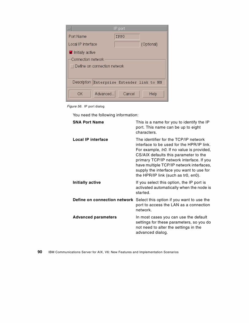
Figure 56. IP port dialog
You need the following information:
SNA Port Name This is a name for you to identify the IPport. This name can be up to eightcharacters.
Local IP interface The identifier for the TCP/IP networkinterface to be used for the HPR/IP link.For example, tr0. If no value is provided,CS/AIX defaults this parameter to theprimary TCP/IP network interface. If youhave multiple TCP/IP network interfaces,supply the interface you want to use forthe HPR/IP link (such as tr0, en0).
Initially active If you select this option, the IP port isactivated automatically when the node isstarted.
Define on connection network Select this option if you want to use theport to access the LAN as a connectionnetwork.
Advanced parameters In most cases you can use the defaultsettings for these parameters, so you donot need to alter the settings in theadvanced dialog.
90 IBM Communications Server for AIX, V6: New Features and Implementation Scenarios
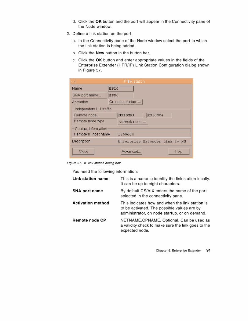
d. Click the OK button and the port will appear in the Connectivity pane ofthe Node window.
2. Define a link station on the port:
a. In the Connectivity pane of the Node window select the port to whichthe link station is being added.
b. Click the New button in the button bar.
c. Click the OK button and enter appropriate values in the fields of theEnterprise Extender (HPR/IP) Link Station Configuration dialog shownin Figure 57.
Figure 57. IP link station dialog box
You need the following information:
Link station name This is a name to identify the link station locally.It can be up to eight characters.
SNA port name By default CS/AIX enters the name of the portselected in the connectivity pane.
Activation method This indicates how and when the link station isto be activated. The possible values are byadministrator, on node startup, or on demand.
Remote node CP NETNAME.CPNAME. Optional. Can be used asa validity check to make sure the link goes to theexpected node.
Chapter 6. Enterprise Extender 91
Remote node type Network node, end node, or discover.
Remote IP host name To configure a selective link station enter the IPhostname or dotted-decimal IP address of theremote station.
Advanced parameters In most cases you can use the default settingsfor these parameters, so you do not need to alterthe settings in the advanced dialog.
d. Click the OK button and the link station will appear beneath the port towhich it belongs in the Connectivity pane of the Node window.
Note that Enterprise Extender links support only independent LU traffic. Thatmeans that if dependent LUs must be supported, DLUR must be configuredon the CS/AIX node.
6.4 Scenario
For this section we used the following equipment:
• Two RS/6000s running AIX Version 4.3.3.0 with the latest maintenancelevel, and Communications Server for AIX, Version 6
• A PC running Windows NT and IBM Personal Communications forWindows NT, Version 4.3 (PCOMM)
• A host running CS for OS/390
We used DLUR to show that Enterprise Extender provides a mechanism fortransporting SNA protocols over the IP network.
DLUR is an APPN feature that allows dependent LU sessions without a directconnection to a host. The Dependent LU Requester (DLUR) communicateswith a Dependent LU Server (DLUS) over an APPN network. DLUR must beavailable on the node where the LUs are located but DLUR is not required onany intermediate nodes in the session route.
By using HPR/IP links, the session route between DLUR and DLUS will takeplace in an IP network but taking advantage of APPN features such as HPR.Sessions between DLUR and DLUS will be routed over an RTP connection.
The following configuration steps are required for this scenario:
1. Configure EE support on the rs60003 machine including DLUR
2. Configure EE support on the rs60004 machine
3. Activate CS/AIX resources on both nodes
92 IBM Communications Server for AIX, V6: New Features and Implementation Scenarios
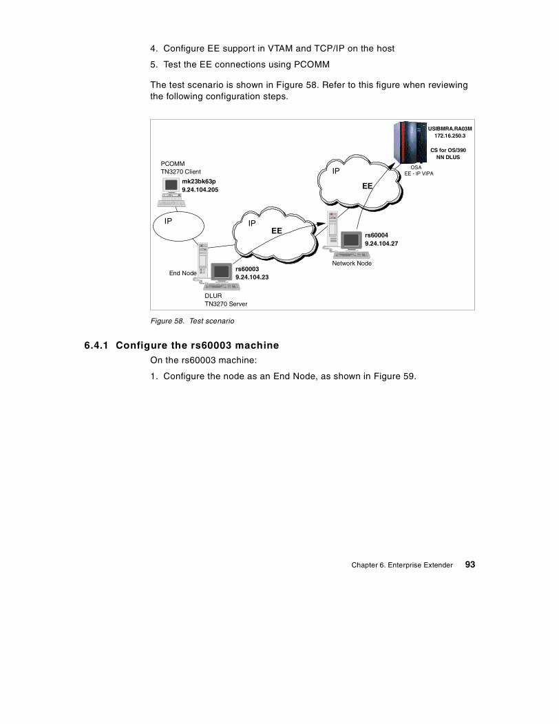
4. Configure EE support in VTAM and TCP/IP on the host
5. Test the EE connections using PCOMM
The test scenario is shown in Figure 58. Refer to this figure when reviewingthe following configuration steps.
Figure 58. Test scenario
6.4.1 Configure the rs60003 machineOn the rs60003 machine:
1. Configure the node as an End Node, as shown in Figure 59.
OSAPCOMMTN3270 Client
Network Node
DLURTN3270 Server
CS for OS/390NN DLUS
EE - IP VIPA
USIBMRA.RA03M172.16.250.3
End Node
rs600049.24.104.27
rs600039.24.104.23
mk23bk63p9.24.104.205
IP IP
IP
EE
EE
Chapter 6. Enterprise Extender 93
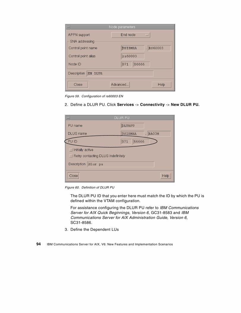
Figure 59. Configuration of rs60003 EN
2. Define a DLUR PU. Click Services -> Connectivity -> New DLUR PU.
Figure 60. Definition of DLUR PU
The DLUR PU ID that you enter here must match the ID by which the PU isdefined within the VTAM configuration.
For assistance configuring the DLUR PU refer to IBM CommunicationsServer for AIX Quick Beginnings, Version 6, GC31-8583 and IBMCommunications Server for AIX Administration Guide, Version 6,SC31-8586.
3. Define the Dependent LUs
94 IBM Communications Server for AIX, V6: New Features and Implementation Scenarios
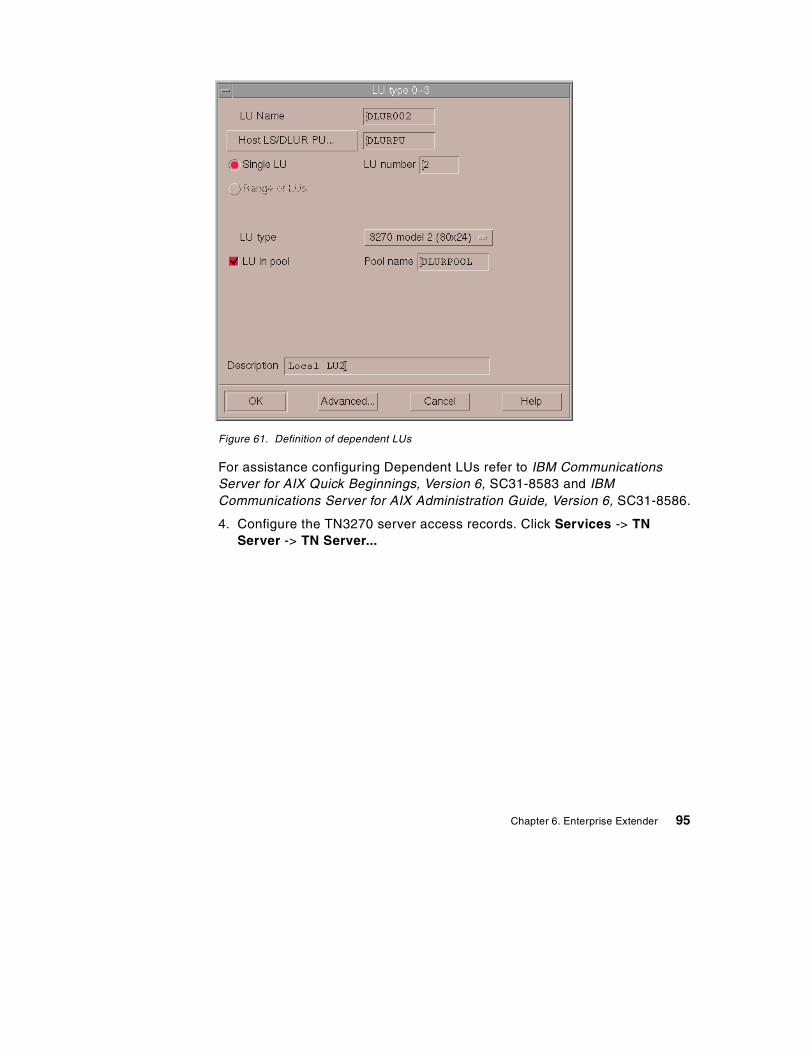
Figure 61. Definition of dependent LUs
For assistance configuring Dependent LUs refer to IBM CommunicationsServer for AIX Quick Beginnings, Version 6, SC31-8583 and IBMCommunications Server for AIX Administration Guide, Version 6, SC31-8586.
4. Configure the TN3270 server access records. Click Services -> TNServer -> TN Server...
Chapter 6. Enterprise Extender 95
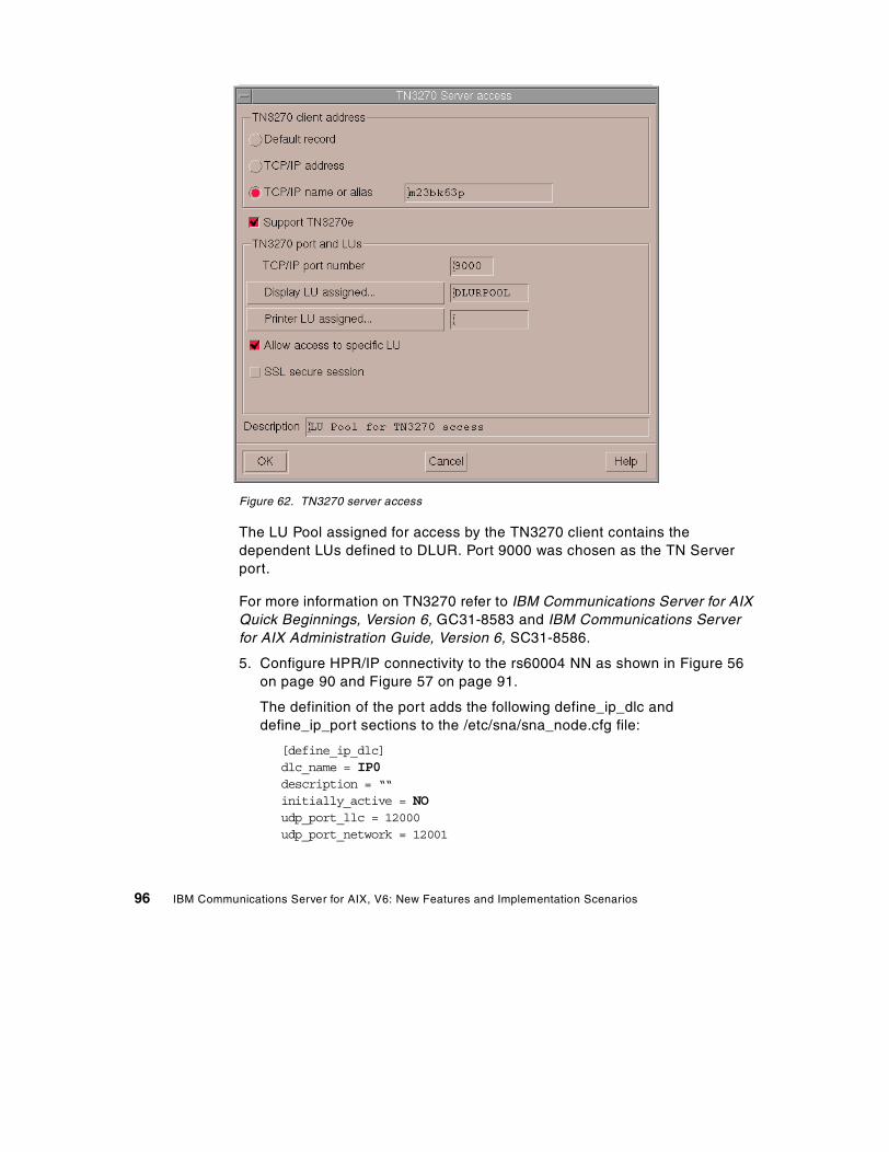
Figure 62. TN3270 server access
The LU Pool assigned for access by the TN3270 client contains thedependent LUs defined to DLUR. Port 9000 was chosen as the TN Serverport.
For more information on TN3270 refer to IBM Communications Server for AIXQuick Beginnings, Version 6, GC31-8583 and IBM Communications Serverfor AIX Administration Guide, Version 6, SC31-8586.
5. Configure HPR/IP connectivity to the rs60004 NN as shown in Figure 56on page 90 and Figure 57 on page 91.
The definition of the port adds the following define_ip_dlc anddefine_ip_port sections to the /etc/sna/sna_node.cfg file:
[define_ip_dlc]dlc_name = IP0description = ““initially_active = NOudp_port_llc = 12000udp_port_network = 12001
96 IBM Communications Server for AIX, V6: New Features and Implementation Scenarios

udp_port_high = 12002udp_port_medium = 12003udp_port_low = 12004ip_precedence_llc = 6ip_precedence_network = 6ip_precedence_high = 4ip_precedence_medium = 2ip_precedence_low = 1
[define_ip_port]port_name = IPP0description = HPR/IP Portdetermined_ip_address = 9.24.104.23lsap_address = 0x04dlc_name = IP0initially_active = YESmax_rcv_btu_size = 1500tot_link_act_lim = 4096inb_link_act_lim = 0out_link_act_lim = 0act_xid_exchange_limit = 9nonact_xid_exchange_limit = 5max_ifrm_rcvd = 7target_pacing_count = 7max_send_btu_size = 1500implicit_cp_cp_sess_support = YESimplicit_limited_resource = NOimplicit_deact_timer = 30implicit_uplink_to_en = NOeffect_cap = 3993600connect_cost = 0byte_cost = 0security = SEC_NONSECUREprop_delay = PROP_DELAY_LANuser_def_parm_1 = 128user_def_parm_2 = 128user_def_parm_3 = 128local_ip_interface = ““react_timer = 30react_timer_retry = 65535ack_timeout = 2000max_retry = 10liveness_timeout = 2000short_hold_mode = NO
Note: When you use Motif Administration to define a port for a particularlink protocol, CS/AIX automatically defines a DLC for the port if a DLC of
Chapter 6. Enterprise Extender 97

that type has not already been defined. For command-line configuration,you must define the port and DLC using different commands.
The define_ip_ls section in the /etc/sna/sna_node.cfg file looks like this:
[define_ip_ls]ls_name = IPL0description = EE Link to NN rs60004port_name = IPP0adj_cp_name = USIBMRA.RS60004adj_cp_type = NETWORK_NODEmax_send_btu_size = 1500ls_attributes = SNAcp_cp_sess_support = YESdefault_nn_server = YESlsap_address = 0x04determined_ip_address = 9.24.104.27auto_act_supp = NOtg_number = 0limited_resource = NOdisable_remote_act = NOlink_deact_timer = 30use_default_tg_chars = YESeffect_cap = 3993600connect_cost = 0byte_cost = 0security = SEC_NONSECUREprop_delay = PROP_DELAY_LANuser_def_parm_1 = 128user_def_parm_2 = 128user_def_parm_3 = 128target_pacing_count = 7max_ifrm_rcvd = 0branch_link_type = NONEadj_brnn_cp_support = ALLOWEDinitially_active = YESrestart_on_normal_deact = NOreact_timer = 30react_timer_retry = 65535remote_ip_host = rs60004ack_timeout = 2000max_retry = 10liveness_timeout = 2000short_hold_mode = NO
98 IBM Communications Server for AIX, V6: New Features and Implementation Scenarios
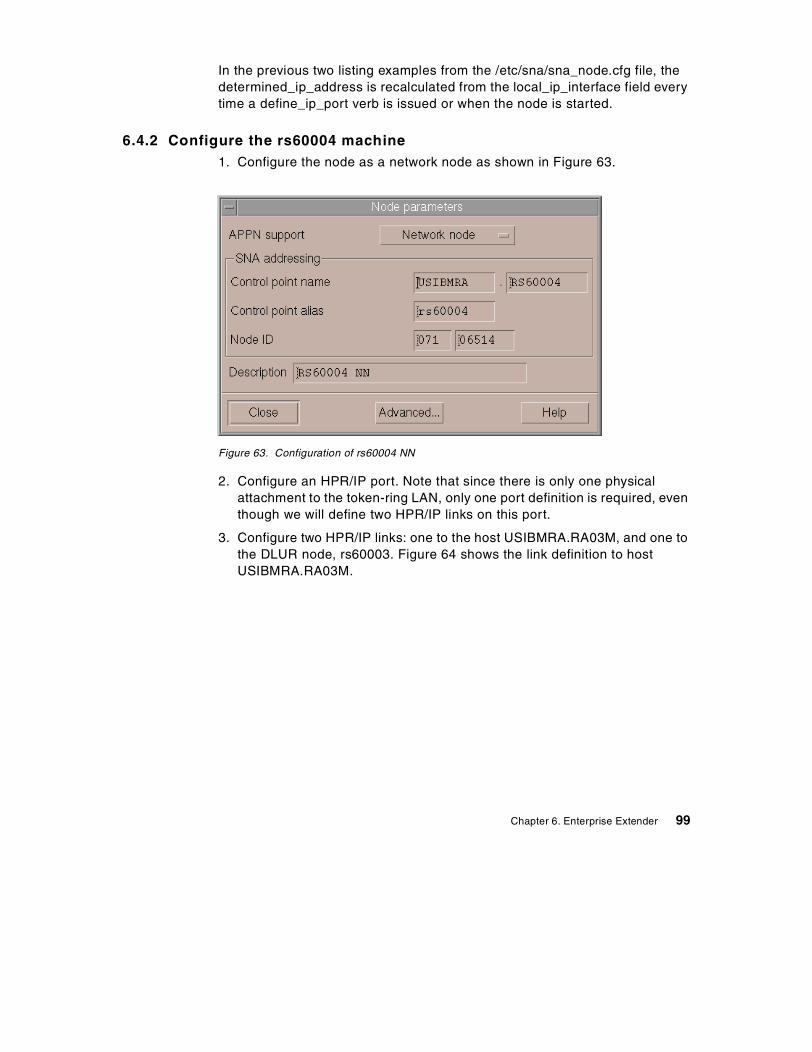
In the previous two listing examples from the /etc/sna/sna_node.cfg file, thedetermined_ip_address is recalculated from the local_ip_interface field everytime a define_ip_port verb is issued or when the node is started.
6.4.2 Configure the rs60004 machine1. Configure the node as a network node as shown in Figure 63.
Figure 63. Configuration of rs60004 NN
2. Configure an HPR/IP port. Note that since there is only one physicalattachment to the token-ring LAN, only one port definition is required, eventhough we will define two HPR/IP links on this port.
3. Configure two HPR/IP links: one to the host USIBMRA.RA03M, and one tothe DLUR node, rs60003. Figure 64 shows the link definition to hostUSIBMRA.RA03M.
Chapter 6. Enterprise Extender 99
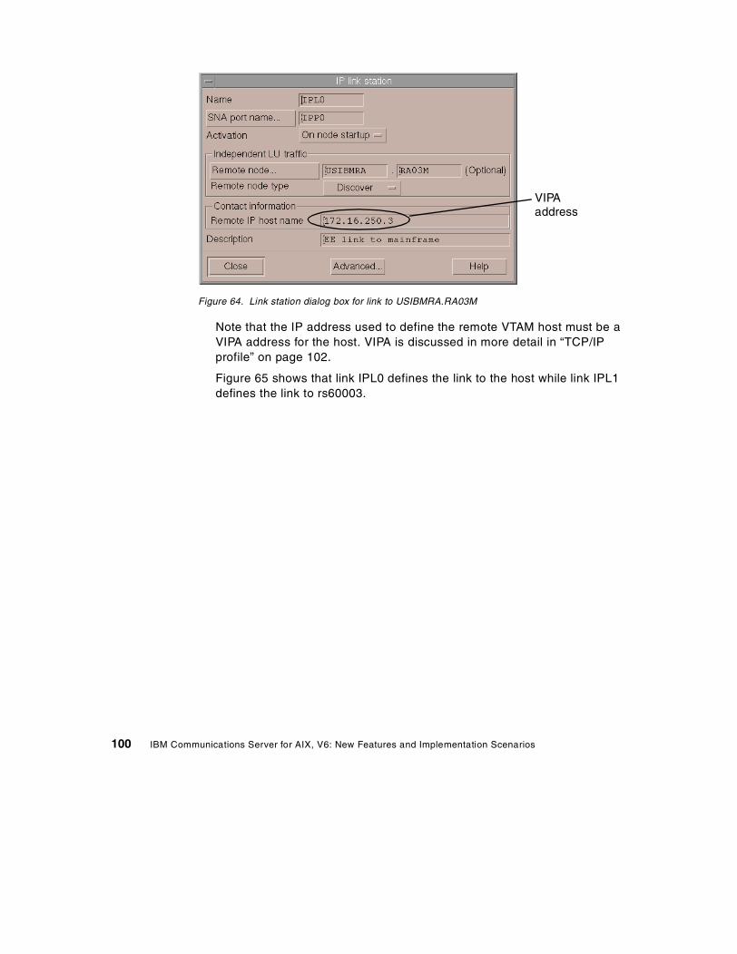
Figure 64. Link station dialog box for link to USIBMRA.RA03M
Note that the IP address used to define the remote VTAM host must be aVIPA address for the host. VIPA is discussed in more detail in “TCP/IPprofile” on page 102.
Figure 65 shows that link IPL0 defines the link to the host while link IPL1defines the link to rs60003.
VIPAaddress
100 IBM Communications Server for AIX, V6: New Features and Implementation Scenarios
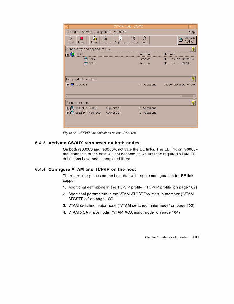
Figure 65. HPR/IP link definitions on host RS60004
6.4.3 Activate CS/AIX resources on both nodesOn both rs60003 and rs60004, activate the EE links. The EE link on rs60004that connects to the host will not become active until the required VTAM EEdefinitions have been completed there.
6.4.4 Configure VTAM and TCP/IP on the hostThere are four places on the host that will require configuration for EE linksupport:
1. Additional definitions in the TCP/IP profile (“TCP/IP profile” on page 102)
2. Additional parameters in the VTAM ATCSTRxx startup member (“VTAMATCSTRxx” on page 102)
3. VTAM switched major node (“VTAM switched major node” on page 103)
4. VTAM XCA major node (“VTAM XCA major node” on page 104)
Chapter 6. Enterprise Extender 101
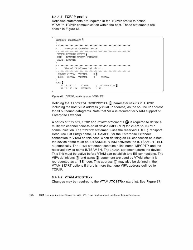
6.4.4.1 TCP/IP profileDefinition statements are required in the TCP/IP profile to defineVTAM-to-TCP/IP communication within the host. These statements areshown in Figure 66.
Figure 66. TCP/IP profile data for VTAM EE
Defining the IPCONFIG SOURCEVIPA (1) parameter results in TCP/IPincluding the host VIPA address (virtual IP address) as the source IP addressfor all outbound datagrams. Note that VIPA is required for VTAM support ofEnterprise Extender.
A series of DEVICE, LINK and START statements (2) is required to define amultipath channel point-to-point device (MPCPTP) for VTAM-to-TCP/IPcommunication. The DEVICE statement uses the reserved TRLE (TransportResource List Entry) name, IUTSAMEH, for the Enterprise Extenderconnection to VTAM on this host. When defining an EE connection on a host,the device name must be IUTSAMEH. VTAM activates the IUTSAMEH TRLEautomatically. The LINK statement contains a link name, MPCPTP, and thereserved device name IUTSAMEH. The START statement starts the device.This link must be active before VTAM can establish any EE connections. TheVIPA definitions (3) and HOME (4) statement are used by VTAM when it isrepresented as an EE node. This address (5) may also be defined in theVTAM START options if there is more than one VIPA address defined toTCP/IP.
6.4.4.2 VTAM ATCSTRxxChanges may be required to the VTAM ATCSTRxx start list. See Figure 67.
IPCONFIG SOURCEVIPA 1;; *********************************************************; Enterprise Extender Device; *********************************************************DEVICE IUTSAMEH MPCPTP 2LINK IUTSAMEH MPCPTP IUTSAMEHSTART IUTSAMEH;; *********************************************************; Virtual IP Address Definition; *********************************************************DEVICE VIPA3A VIRTUAL 0 3LINK VIPA3A VIRTUAL 0 VIPA3A
;HOME 4
172.16.250.3 VIPA3A ; 1st VIPA Link 5172.16.250.254 IUTSAMEH ; EE
102 IBM Communications Server for AIX, V6: New Features and Implementation Scenarios
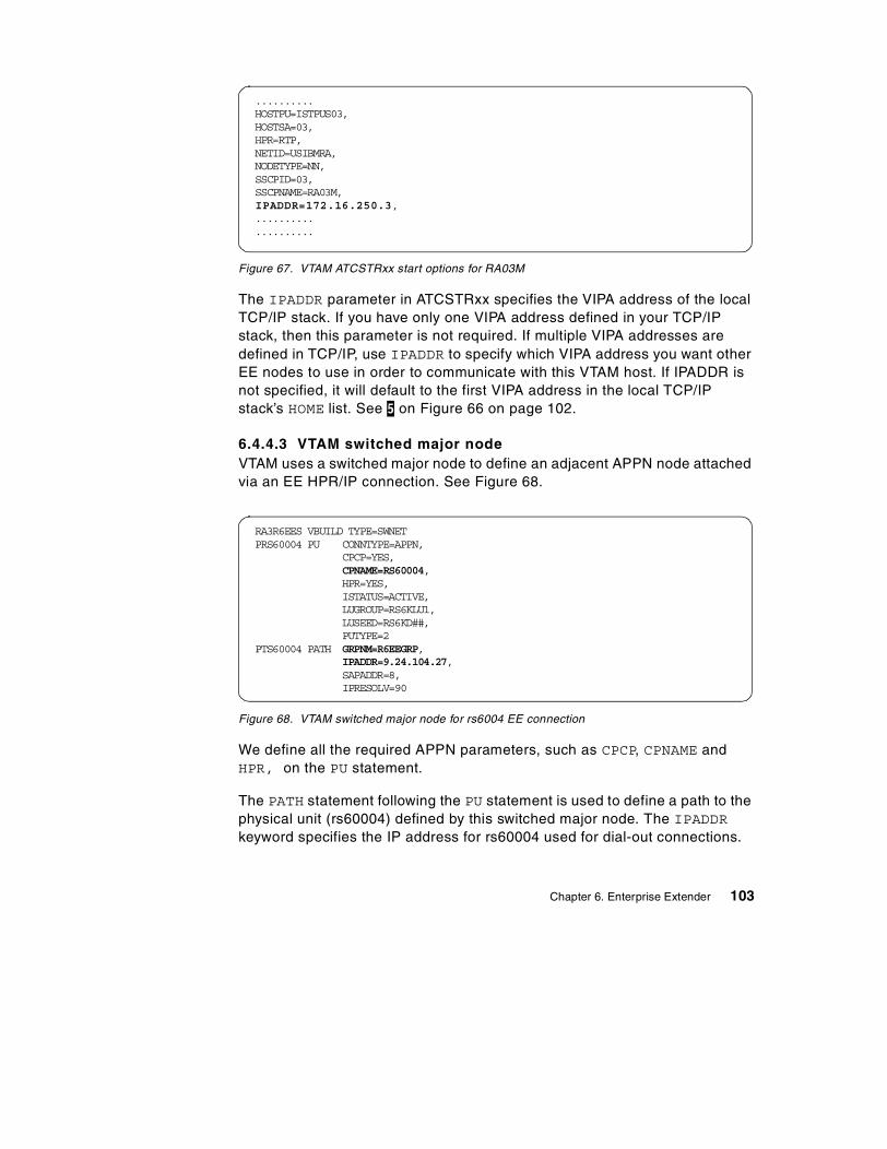
Figure 67. VTAM ATCSTRxx start options for RA03M
The IPADDR parameter in ATCSTRxx specifies the VIPA address of the localTCP/IP stack. If you have only one VIPA address defined in your TCP/IPstack, then this parameter is not required. If multiple VIPA addresses aredefined in TCP/IP, use IPADDR to specify which VIPA address you want otherEE nodes to use in order to communicate with this VTAM host. If IPADDR isnot specified, it will default to the first VIPA address in the local TCP/IPstack’s HOME list. See 5 on Figure 66 on page 102.
6.4.4.3 VTAM switched major nodeVTAM uses a switched major node to define an adjacent APPN node attachedvia an EE HPR/IP connection. See Figure 68.
Figure 68. VTAM switched major node for rs6004 EE connection
We define all the required APPN parameters, such as CPCP, CPNAME andHPR, on the PU statement.
The PATH statement following the PU statement is used to define a path to thephysical unit (rs60004) defined by this switched major node. The IPADDRkeyword specifies the IP address for rs60004 used for dial-out connections.
..........HOSTPU=ISTPUS03,HOSTSA=03,HPR=RTP,NETID=USIBMRA,NODETYPE=NN,SSCPID=03,SSCPNAME=RA03M,IPADDR=172.16.250.3,....................
RA3R6EES VBUILD TYPE=SWNETPRS60004 PU CONNTYPE=APPN,
CPCP=YES,CPNAME=RS60004,HPR=YES,ISTATUS=ACTIVE,LUGROUP=RS6KLU1,LUSEED=RS6KD##,PUTYPE=2
PTS60004 PATH GRPNM=R6EEGRP,IPADDR=9.24.104.27,SAPADDR=8,IPRESOLV=90
Chapter 6. Enterprise Extender 103
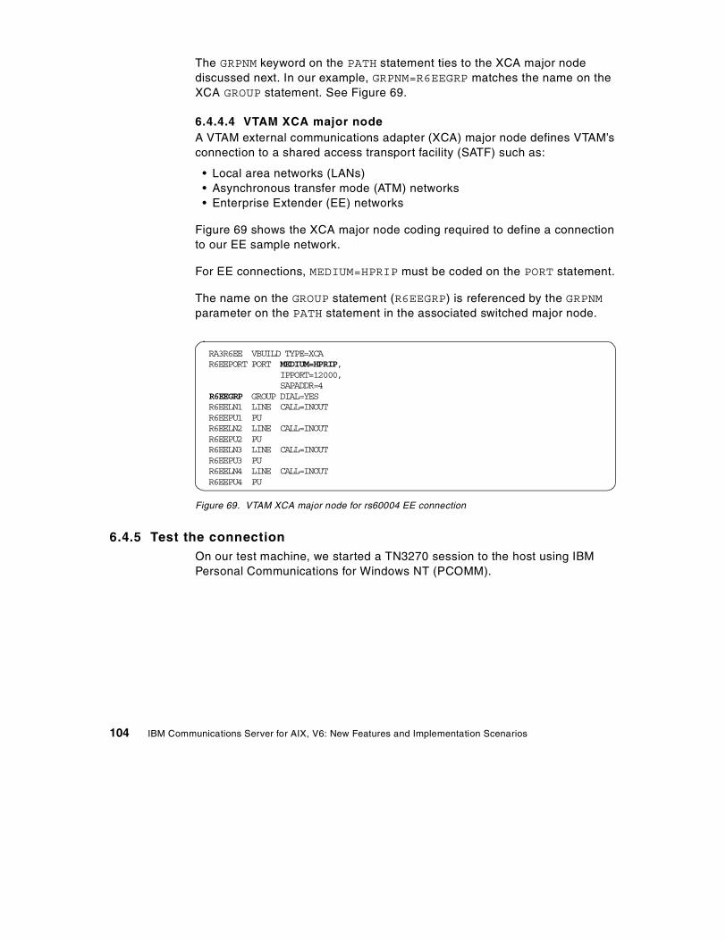
The GRPNM keyword on the PATH statement ties to the XCA major nodediscussed next. In our example, GRPNM=R6EEGRP matches the name on theXCA GROUP statement. See Figure 69.
6.4.4.4 VTAM XCA major nodeA VTAM external communications adapter (XCA) major node defines VTAM’sconnection to a shared access transport facility (SATF) such as:
• Local area networks (LANs)• Asynchronous transfer mode (ATM) networks• Enterprise Extender (EE) networks
Figure 69 shows the XCA major node coding required to define a connectionto our EE sample network.
For EE connections, MEDIUM=HPRIP must be coded on the PORT statement.
The name on the GROUP statement (R6EEGRP) is referenced by the GRPNMparameter on the PATH statement in the associated switched major node.
Figure 69. VTAM XCA major node for rs60004 EE connection
6.4.5 Test the connectionOn our test machine, we started a TN3270 session to the host using IBMPersonal Communications for Windows NT (PCOMM).
RA3R6EE VBUILD TYPE=XCAR6EEPORT PORT MEDIUM=HPRIP,
IPPORT=12000,SAPADDR=4
R6EEGRP GROUP DIAL=YESR6EELN1 LINE CALL=INOUTR6EEPU1 PUR6EELN2 LINE CALL=INOUTR6EEPU2 PUR6EELN3 LINE CALL=INOUTR6EEPU3 PUR6EELN4 LINE CALL=INOUTR6EEPU4 PU
104 IBM Communications Server for AIX, V6: New Features and Implementation Scenarios
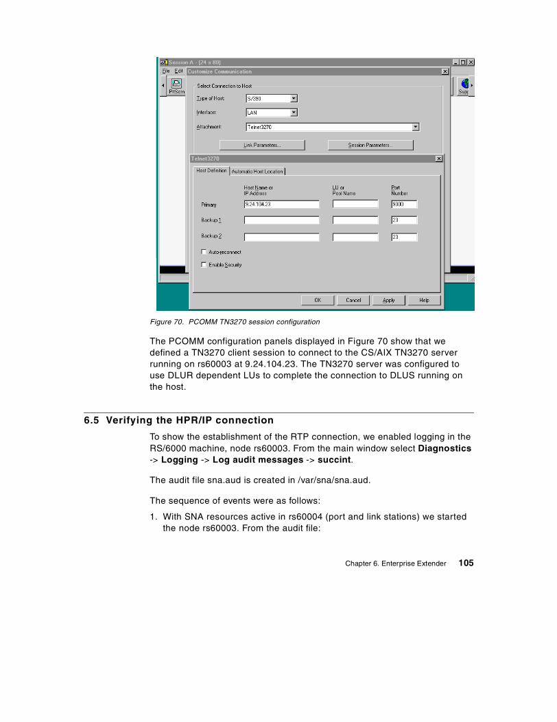
Figure 70. PCOMM TN3270 session configuration
The PCOMM configuration panels displayed in Figure 70 show that wedefined a TN3270 client session to connect to the CS/AIX TN3270 serverrunning on rs60003 at 9.24.104.23. The TN3270 server was configured touse DLUR dependent LUs to complete the connection to DLUS running onthe host.
6.5 Verifying the HPR/IP connection
To show the establishment of the RTP connection, we enabled logging in theRS/6000 machine, node rs60003. From the main window select Diagnostics-> Logging -> Log audit messages -> succint.
The audit file sna.aud is created in /var/sna/sna.aud.
The sequence of events were as follows:
1. With SNA resources active in rs60004 (port and link stations) we startedthe node rs60003. From the audit file:
Chapter 6. Enterprise Extender 105
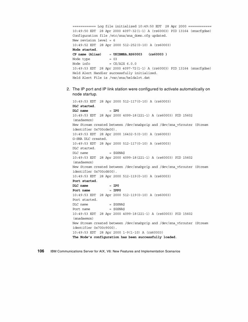
============ Log file initialized 10:49:50 EDT 28 Apr 2000 ============10:49:50 EDT 28 Apr 2000 4097-32(1-1) A (rs60003) PID 13164 (snacfgdae)Configuration file /etc/sna/sna_domn.cfg updated.New revision level = 610:49:52 EDT 28 Apr 2000 512-252(0-10) A (rs60003)Node started.CP name (Alias) = USIBMRA.RS60003 (rs60003 )Node type = 03Node info = CS/AIX 6.0.010:49:53 EDT 28 Apr 2000 4097-72(1-1) A (rs60003) PID 13164 (snacfgdae)Held Alert Handler successfully initialized.Held Alert File is /var/sna/heldalrt.dat
2. The IP port and IP link station were configured to activate automatically onnode startup.
10:49:53 EDT 28 Apr 2000 512-117(0-10) A (rs60003)DLC started.DLC name = IP010:49:53 EDT 28 Apr 2000 4099-18(221-1) A (rs60003) PID 15602(snadaemon)New Stream created between /dev/snahprip and /dev/sna_v5router (Streamidentifier 0x700cde00).10:49:53 EDT 28 Apr 2000 16432-5(0-10) A (rs60003)G-SNA DLC created.10:49:53 EDT 28 Apr 2000 512-117(0-10) A (rs60003)DLC started.DLC name = $GSNA$10:49:53 EDT 28 Apr 2000 4099-18(221-1) A (rs60003) PID 15602(snadaemon)New Stream created between /dev/snahprip and /dev/sna_v5router (Streamidentifier 0x700cd600).10:49:53 EDT 28 Apr 2000 512-119(0-10) A (rs60003)Port started.DLC name = IP0Port name = IPP010:49:53 EDT 28 Apr 2000 512-119(0-10) A (rs60003)Port started.DLC name = $GSNA$Port name = $GSNA$10:49:53 EDT 28 Apr 2000 4099-18(221-1) A (rs60003) PID 15602(snadaemon)New Stream created between /dev/snahprip and /dev/sna_v5router (Streamidentifier 0x700c9000).10:49:53 EDT 28 Apr 2000 1-9(1-10) A (rs60003)The Node’s configuration has been successfully loaded.
106 IBM Communications Server for AIX, V6: New Features and Implementation Scenarios

10:49:53 EDT 28 Apr 2000 512-115(0-10) A (rs60003)HPR-capable link station started.Port name = IPP0LS name = IPL0Adjacent CP name = USIBMRA.RS60004Adjacent CP type = 02TG number = 21Last TG number = 0ANR Label = 90FFLink level error recovery = 00Adjacent RTP support = 01
The above information is a result of the XID3 negotiation during the linkactivation.
3. After the link setup, both nodes set up the CP-CP sessions (two sessions).And because the link is an HPR/IP link, the CP-CP sessions flow over anRTP connection with COS CPSVCMG. Notice that both sessions use thesame RTP connection.
10:49:53 EDT 28 Apr 2000 512-726(0-10) A (rs60003)Adjacent CP contacted.Adjacent CP name = USIBMRA.RS6000410:49:53 EDT 28 Apr 2000 512-660(0-10) A (rs60003)RTP Connection has been established.Connection name = @R000001Partner name = RS60004COS name = CPSVCMGLocal TCID = 0000000001000000Remote TCID = 000000000400000010:49:53 EDT 28 Apr 2000 512-307(0-10) A (rs60003)LU6.2 session activated.Local LU (Alias) = USIBMRA.RS60003 (rs60003 )Partner LU (Alias) = USIBMRA.RS60004 (@I000001)Mode name = CPSVCMGSession identifier = F25FB4F4803F407ASession polarity = 02Session type = 01LS name = @R000001LFSID = 0200000010:49:53 EDT 28 Apr 2000 512-307(0-10) A (rs60003)LU6.2 session activated.Local LU (Alias) = USIBMRA.RS60003 (rs60003 )Partner LU (Alias) = USIBMRA.RS60004 (@I000001)Mode name = CPSVCMGSession identifier = F25FB3F4803F18C9Session polarity = 03Session type = 02
Chapter 6. Enterprise Extender 107

LS name = @R000001LFSID = 0200000110:49:53 EDT 28 Apr 2000 512-727(1-10) A (rs60003)CP-CP sessions established.Adjacent CP name = USIBMRA.RS600041015 compliant = 3Topology awareness of CP-CP sessions support = 01CP Capabilities :000C12C1 00000000 E2844000
The above message indicates that the BIND for the CP-CP session hasstarted and the CP capabilities have been exchanged.
4. The DLURPU was activated. Information about the best possible HPRroute for the sessions that will follow is collected by the Route_Setupcommand:
10:50:00 EDT 28 Apr 2000 512-660(0-10) A (rs60003)RTP Connection has been established.Connection name = @R000003Partner name = RS60004COS name = RSETUPLocal TCID = 0000000003000000Remote TCID = 0000000005000000
5. Next, the RTP connections used to carry the CP-CP sessions between theDLUR and the DLUS (mode CPSVRMGR) are started.
10:50:00 EDT 28 Apr 2000 512-660(0-10) A (rs60003)RTP Connection has been established.Connection name = @R000002Partner name = RA03MCOS name = SNASVCMGLocal TCID = 0000000002000000Remote TCID = 31818CC10000016C10:50:00 EDT 28 Apr 2000 512-307(0-10) A (rs60003)LU6.2 session activated.Local LU (Alias) = USIBMRA.RS60003 (rs60003 )Partner LU (Alias) = USIBMRA.RA03M (@I000002)Mode name = CPSVRMGRSession identifier = F25FB4F4803F407DSession polarity = 02Session type = 01LS name = @R000002LFSID = 0200000010:50:00 EDT 28 Apr 2000 512-660(0-10) A (rs60003)RTP Connection has been established.Connection name = @R000004Partner name = RA03M
108 IBM Communications Server for AIX, V6: New Features and Implementation Scenarios

COS name = SNASVCMGLocal TCID = 0000000004000000Remote TCID = 31818CC30000019510:50:00 EDT 28 Apr 2000 512-307(0-10) A (rs60003)LU6.2 session activated.Local LU (Alias) = USIBMRA.RS60003 (rs60003 )Partner LU (Alias) = USIBMRA.RA03M (@I000002)Mode name = CPSVRMGRSession identifier = C7335B7CB30EA363Session polarity = 03Session type = 02LS name = @R000004LFSID = 02000001
6. The SSCP-PU and SSCP-LU sessions between DLUS and DLUR getestablished; see Figure 71 on page 110.
10:50:00 EDT 28 Apr 2000 512-592(0-10) A (rs60003)A pipe to a DLUS has activatedDLUS name = USIBMRA.RA03MDLUS persistent pipe support = 02Persistent pipe active = 0010:50:00 EDT 28 Apr 2000 512-740(0-10) A (rs60003)A PU-SSCP session has been activated.PU name = DLURPU10:50:00 EDT 28 Apr 2000 512-560(0-10) A (rs60003)An LU-SSCP session has been activated for LU type 0, 1, 2, or 3.PU name = DLURPUNAU address = 02LU name = DLUR00210:50:00 EDT 28 Apr 2000 512-560(0-10) A (rs60003)An LU-SSCP session has been activated for LU type 0, 1, 2, or 3.PU name = DLURPUNAU address = 03LU name = DLUR00310:50:00 EDT 28 Apr 2000 512-560(0-10) A (rs60003)An LU-SSCP session has been activated for LU type 0, 1, 2, or 3.PU name = DLURPUNAU address = 04LU name = DLUR004
Chapter 6. Enterprise Extender 109
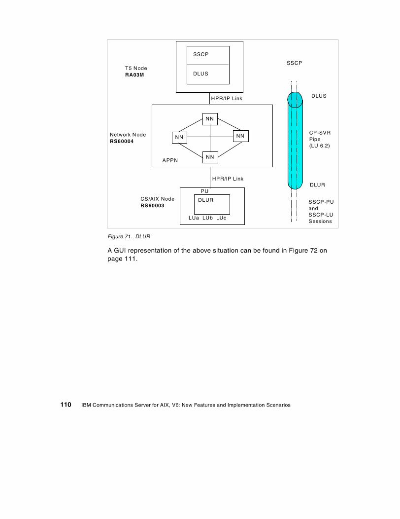
Figure 71. DLUR
A GUI representation of the above situation can be found in Figure 72 onpage 111.
NN
NN
NN
NN
APPN
SSCP
DLUS
CS/AIX NodeRS60003
T5 NodeRA03M
SSCP
DLUS
CP-SVRPipe(LU 6.2)
DLUR
SSCP-PUandSSCP-LUSessions
DLUR
PU
LUa LUb LUc
HPR/IP Link
HPR/IP Link
Network NodeRS60004
110 IBM Communications Server for AIX, V6: New Features and Implementation Scenarios
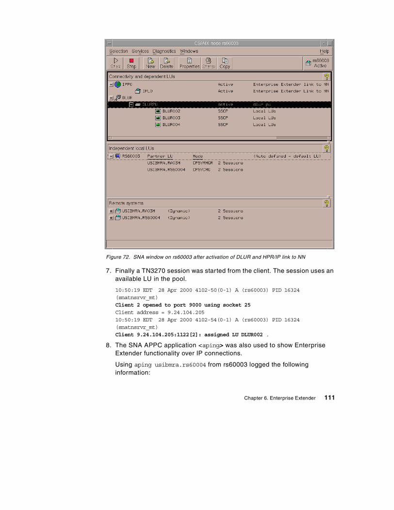
Figure 72. SNA window on rs60003 after activation of DLUR and HPR/IP link to NN
7. Finally a TN3270 session was started from the client. The session uses anavailable LU in the pool.
10:50:19 EDT 28 Apr 2000 4102-50(0-1) A (rs60003) PID 16324(snatnsrvr_mt)Client 2 opened to port 9000 using socket 25Client address = 9.24.104.20510:50:19 EDT 28 Apr 2000 4102-54(0-1) A (rs60003) PID 16324(snatnsrvr_mt)Client 9.24.104.205:1122[2]: assigned LU DLUR002 .
8. The SNA APPC application <aping> was also used to show EnterpriseExtender functionality over IP connections.
Using aping usibmra.rs60004 from rs60003 logged the followinginformation:
Chapter 6. Enterprise Extender 111

10:50:37 EDT 28 Apr 2000 8195-6(0-1) A (rs60003) PID 21726 (aping)Unknown CPI-C symbolic destination name (4150494e47442020) specified.10:50:37 EDT 28 Apr 2000 8193-8(213-1) A (rs60003) PID 21726 (aping)APPC invoking TP started.TP ID = 0000000001000000TP name =c3d7c9c36dc4c5c6c1e4d3e36de3d7d5c1d4c540404040404040404040404040404040404040404040404040404040404040404040404040404040404040404010:50:37 EDT 28 Apr 2000 8195-0(0-1) A (rs60003) PID 21726 (aping)New TP instance started for CPI-C. TP id = 0000000010:50:37 EDT 28 Apr 2000 512-660(0-10) A (rs60003)RTP Connection has been established.Connection name = @R000005Partner name = RS60004COS name = SNASVCMGLocal TCID = 0000000005000000Remote TCID = 000000000800000010:50:37 EDT 28 Apr 2000 512-307(0-10) A (rs60003)LU6.2 session activated.Local LU (Alias) = USIBMRA.RS60003 (rs60003 )Partner LU (Alias) = USIBMRA.RS60004 (@I000001)Mode name = SNASVCMGSession identifier = F25FB4F4803F4080Session polarity = 02Session type = 01LS name = @R000005LFSID = 0200000010:50:37 EDT 28 Apr 2000 512-32(0-10) A (rs60003)Session limits changed.Local LU (Alias) = USIBMRA.RS60003 (rs60003 )Partner LU (Alias) = USIBMRA.RS60004 (@I000001)Mode name = #INTERNew session limit = 8Min. contention winner limit = 4Min. contention loser limit = 4Termination count = 010:50:37 EDT 28 Apr 2000 512-660(0-10) A (rs60003)RTP Connection has been established.Connection name = @R000006Partner name = RS60004COS name = #INTERLocal TCID = 0000000006000000Remote TCID = 000000000900000010:50:37 EDT 28 Apr 2000 512-307(0-10) A (rs60003)LU6.2 session activated.Local LU (Alias) = USIBMRA.RS60003 (rs60003 )Partner LU (Alias) = USIBMRA.RS60004 (@I000001)
112 IBM Communications Server for AIX, V6: New Features and Implementation Scenarios

Mode name = #INTERSession identifier = F25FB4F4803F4082Session polarity = 02Session type = 01LS name = @R000006LFSID = 0200000010:50:37 EDT 28 Apr 2000 8195-2(0-1) A (rs60003) PID 21726 (aping)New CPI-C conversation started. CPI-C conversation ID = 010000010000000010:50:38 EDT 28 Apr 2000 8195-3(0-1) A (rs60003) PID 21726 (aping)CPI-C conversation deallocated. CPI-C conversation ID = 0100000100000000
Note: The RTP connection with COS SNASVCMG is established to perform aCNOS (Change Number of Sessions) for mode #INTER, after which the RTPconnection that carries the actual #INTER session (aping session) is started.
Chapter 6. Enterprise Extender 113

114 IBM Communications Server for AIX, V6: New Features and Implementation Scenarios

Chapter 7. Branch Extender
This chapter describes the functionality of Branch Extender and how it isconfigured, and an example scenario illustrates the use of Branch Extender incombination with HPR.
7.1 Overview
As the name implies, Branch Extender is designed for networks that can bedivided into distinct areas, such as separate branches of a large organization.It works by separating out branch offices from the main APPN WAN backbonenetwork, for example, the organization’s headquarters network.
Each branch contains a node of the type called branch network node (BrNN),which combines the functions of an APPN network node and an APPN endnode.
To the backbone network, the BrNN appears as an end node, connected to itsnetwork node server (NNS) in the backbone network. Because the BrNNappears as an end node, it does not receive topology information from thebackbone network (topology information is transmitted only between networknodes).
The BrNN registers all resources in the branch with its NNS as though theywere located on the BrNN itself.This means that the nodes in the backbonenetwork can locate resources in the branch without having to be aware of theseparate nodes in the branch, thus reducing the amount of topologyinformation that must be stored. While a BrNN knows the topology of its localbranch, it knows nothing of the uplink topology.
To the branch network, the BrNN appears as a network node, acting as theNNS for end nodes in the branch. Each node in the branch sees the rest ofthe network as being connected through its NNS, in the same way as for astandard NNS. When the BrNN can’t resolve a request for network serviceslocally, it refers the request to its NNS, which connects to other NNs usingnormal CP-CP sessions. This can be thought of as default routing. That iswhy a BrNN’s uplink to its NNS may be called the “default routing link”.
For directory services purposes, the BrNN appears to own all branchresources. For route selection purposes, the BrNN appears to be the origin ordestination of all sessions involving branch LUs.
© Copyright IBM Corp. 2000 115
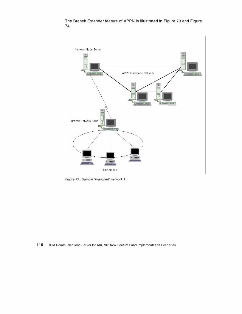
The Branch Extender feature of APPN is illustrated in Figure 73 and Figure74.
Figure 73. Sample “branched” network 1
116 IBM Communications Server for AIX, V6: New Features and Implementation Scenarios
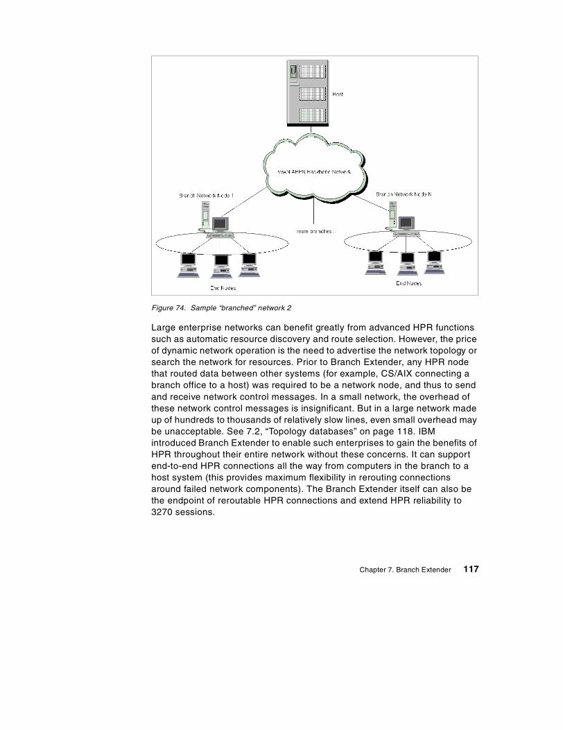
Figure 74. Sample “branched” network 2
Large enterprise networks can benefit greatly from advanced HPR functionssuch as automatic resource discovery and route selection. However, the priceof dynamic network operation is the need to advertise the network topology orsearch the network for resources. Prior to Branch Extender, any HPR nodethat routed data between other systems (for example, CS/AIX connecting abranch office to a host) was required to be a network node, and thus to sendand receive network control messages. In a small network, the overhead ofthese network control messages is insignificant. But in a large network madeup of hundreds to thousands of relatively slow lines, even small overhead maybe unacceptable. See 7.2, “Topology databases” on page 118. IBMintroduced Branch Extender to enable such enterprises to gain the benefits ofHPR throughout their entire network without these concerns. It can supportend-to-end HPR connections all the way from computers in the branch to ahost system (this provides maximum flexibility in rerouting connectionsaround failed network components). The Branch Extender itself can also bethe endpoint of reroutable HPR connections and extend HPR reliability to3270 sessions.
Chapter 7. Branch Extender 117
Technically, a Branch Extender poses as a network node with DLUR supportto computers or 3270 terminals in its local branch. At the same time it posesas an end node to computers in the WAN. By impersonating an end node, aBranch Extender gains the following advantages:
• It does not receive topology data or directory broadcasts from the widearea network. Instead, it lets a network node in the WAN choose routes forcomputers in the branch. A Branch Extender relays data between thebranch and the WAN and enables HPR traffic to flow to computers in thebranch.
• It can register all the branch’s resources to a directory server in the APPNbackbone network so that no manual definitions are needed there.Network efficiency is improved by notifying the central directory server ofeach resource’s location, to greatly reduce or even eliminate broadcastsearches in the WAN.
Branch Extender also allows direct, peer-to-peer communication betweenbranches connected to the same APPN connection network (CN). Though aconnection network configuration is not required, Branch Extender providessubstantial benefit when the uplink and downlink networks are CNs, forexample a branch CN such as token-ring, Ethernet or FDDI connected via aBrNN to a WAN CN such as ATM.
7.2 Topology databases
APPN networks consist of a backbone structure of network nodesinterconnected by TGs, known as intermediate-routing TGs, and TGsconnecting end nodes to adjacent network nodes, virtual routing nodes, orother end nodes, known as endpoint TGs.
Information about the backbone structure of the APPN network is kept withinthe network topology database, which resides on every APPN network node.Information about endpoint TGs is contained within local topology databases,which reside on every APPN node or LEN end node.
The primary use of local and network topology databases is to enable routecalculation when an LU residing in one APPN node wishes to establish asession with an LU residing in another APPN node. The topology databasesenable topology and routing services in the network node (NN) server todetermine all possible routes between the nodes. The local topologydatabase contributes the end node’s TG, while the network topologydatabase supplies the information on network nodes and the TGs betweenthem.
118 IBM Communications Server for AIX, V6: New Features and Implementation Scenarios
7.2.1 Local topology databaseThe local topology database contains information on all of the transmissiongroups (TGs) attached to the node. Every APPN node maintains a localtopology database. An APPN end node uses the information in its localtopology database to send local TG information to its network node server inlocate requests and replies. In a network node, the local topology databaseincludes information about the attached end nodes. In HPR networks, theAPPN end node’s TG information (carried in TG vectors) indicates whetherthe nodes are HPR-capable.
The local topology database is created and maintained by the end nodeTopology Database Manager (TDM). It is not saved across reboots and isrebuilt when the node initializes. Entries in the local topology database arecreated automatically when configuration services informs TDM about newlyactivated or changed TGs. The operator updates the local topology databasethrough configuration services. The local topology database is searched byTDM when it receives a query from route selection services or from sessionservices.
7.2.2 Network topology databaseNetwork nodes in an APPN network need to maintain topology informationabout the location of other nodes in the network and the communicationslinks between them, and to forward this information around the network whenthe topology changes. The information is maintained in a database called thenetwork topology database. As the network grows in size, the amount ofstored information and topology-related network traffic can become large anddifficult to manage. Topology database size is a function of the number ofNNs and links, as well as the frequency of link state changes.
Every APPN network node maintains a network topology database in additionto its local topology database. The network topology database does notinclude information on APPN end nodes, LEN end nodes, or the transmissiongroups attached to them. It includes information only on network nodes in theAPPN network and the transmission groups interconnecting them.
Network nodes in an APPN network send one another topology databaseupdates (TDUs) over CP-CP sessions whenever a resource (network node ora TG between network nodes) is activated or deactivated, or itscharacteristics change. Only the current changes are included in the TDU.Every network node receives the TDU containing the current change, so eachhas the same view of the network. The network topology database is used bythe network node to select routes for sessions that originate at the LUs in itand at the end nodes that it serves. Unlike the directory database, which is
Chapter 7. Branch Extender 119
distributed among network nodes, the network topology database is fullyreplicated on all APPN network nodes. APPN protocols for the distribution ofnetwork topology information ensure that every network node is provided witha complete view of the network backbone topology.
Note: Although the TGs connecting a network node to attached end nodesare not included in the network topology database, the network node,nevertheless, knows of those TGs through its local topology database. Thisinformation is kept locally only and not sent to adjacent network nodes.
The network topology database is created and maintained by TDM and savedacross reboots by the safe-store of network topology database function. In aCS/AIX network node, the network topology database is saved in the file/var/sna/topology.dat.
7.3 Supported configurations
The following sections describe Branch Extender components and capacities.
7.3.1 LinksThe number and type of links over which a BrNN provides network nodeservices to its branch are unrestricted. Although a typical BrNN branch is asingle LAN, a BrNN’s supported network may consist of any combination ofone or more local area network(s), including standard Ethernet, 802.3Ethernet, token-ring, FDDI, ATM LAN Emulation, one or more wide areanetwork link(s), including SDLC, X.25, frame relay using emulated token-ring.
The number and type of links over which a BrNN supports receiving networknode services from an uplink NNS are unrestricted, but a BrNN acts as an ENon uplinks and, as a result, never has more than one NNS at a time.
The same physical medium may support BrNN uplinks and downlinkssimultaneously, as long as the medium supports simultaneous multiple logicalconnections. Example of logical addressing are SDLC multipoint stationsaddresses, IEEE 802.2 Logical Link Control type 2 connections identified byunique SSAP/DSAP pairs, and X.25 Virtual Circuits.
A BrNN will typically have many downlinks and only a few uplinks.
7.3.2 NodesIn a BrNN-served branch, the only active NNs allowed are BrNN(s). All othernodes in the branch are ENs or LEN ENs, and use a BrNN as their server.
120 IBM Communications Server for AIX, V6: New Features and Implementation Scenarios
Two types of BrNN-BrNN connectivity are supported:
1. Cascaded BrNNs. The upper BrNN defines the link as a downlink andassumes an NN role. The lower BrNN defines it as an uplink and assumesan EN role. The lower BrNN, in turn, may be the NNS for resources on itsown downlinks.
2. Parallel (peer) BrNNs. Both BrNNs configure the link between them as anuplink, and appear as ENs to each other. Each BrNN typically has at leastone uplink to the WAN. In this configuration, the BrNN-served downlinksare disjoint, but a given EN can establish CP-CP sessions and register itsresources with either BrNN. The BrNN with which an EN currently hasCP-CP sessions is its NNS; only this BrNN replies positively to a Locaterequest for that EN’s resources.
By definition, a BrNN maintains CP-CP sessions with no more than one nodeoutside its branch network - its current network node server. A BrNN isallowed to have different NN servers from time to time, but only one at a time.If its NNS fails, the BrNN automatically switches to another available NNS,which can be another BrNN. If a link to a preferred NNS becomes operational,the CP-CP sessions to the current NNS can be manually deactivated in orderto activate CP-CP sessions with the preferred NNS.
All DLUR support in a BrNN-served local branch is provided by the BrNN. NoDLUR support may be provided by any node downstream of a BrNN. If BrNNsare cascaded, only the highest BrNN can be a DLUR.
7.3.3 LU-LU sessionsLU-LU sessions between two ENs in the same branch are managed andconnected without the intervention of NNs across the WAN. However, a BrNNrelies on its server for default routing to connect LU-LU sessions betweenLUs in different branches. A BrNN does not try to get complete topology data.It only retains the topology of its local branch. When that information isinsufficient, the BrNN sends a Locate to its NNS asking for assistance inlocating the resource and calculating the route to get there from the BrNN.
To keep these dual faces, although it’s really an NN, a BrNN emulates an ENto its NNS by setting EN parameters in XID and CP-CP capabilities. (TheBrNN determines if the link is downlink or uplink before sending an XID).
Since a BrNN appears to be an EN, it is isolated from the WAN. The NNSdoes not bother to send it TDUs, giving the BrNN no chance to learn aboutcentral directory servers or other NNs or their TGs.
Chapter 7. Branch Extender 121

By default, the BrNN sends a Locate only to its current NNS, since that is theonly NN with which it ever has CP-CP sessions.
A BrNN is an NN inside and shows an NN image to its branch ENs. BranchENs don’t need to know that their NNS is actually a BrNN.
7.4 Implementation
The APPN Branch Extender function is implemented by the APPN BranchNetwork Node, so its implementation involves configuring a CS/AIX node as abranch network node:
To implement Branch Extender, configure the node as follows:
1. Define the node
a. From the Node window select Services -> Configure NodeParameters.
CS/AIX displays the Node Parameters dialog.
APPN support To provide session routing services to othernodes in a branch network that are not part ofthe main APPN backbone network, configure thenode as a branch network node.
Control Point Name Fully qualified control point name for the localnode.
Control Point Alias Local alias for the default local LU. Supply thisvalue if the default local LU is used byindependent LU 6.2 LUs.
Node ID Identifier for the PU on the local node. Supply avalue only if the node will be used for dependenttraffic using the default (control point) LU.
b. Click on the OK button to define the node. When you define the node,CS/AIX automatically defines a default LU with the same name as thecontrol point. That LU can act as the default local LU for the node.
2. Define connectivity
a. To define the port, click Services -> Connectivity -> New Port.
Choose the correct type of port and click OK.
Each port is associated with a specific link protocol and therefore the portdialog depends on the port type. For an Enterprise Extender (HPR/IP)port, for example, the parameters are:
122 IBM Communications Server for AIX, V6: New Features and Implementation Scenarios

Port name The locally known name of the port.
Local IP Interface The identifier for the TCP/IP network interface tobe used for the HPR/IP link. For example, tr0. Ifno value is provided, CS/AIX defaults thisparameter to the primary TCP/IP networkinterface.
Initially Active Whether to activate the port automatically whenthe node is started. This setting enables linkstations that use the port to be activated inresponse to requests from adjacent nodes or ondemand by the local node. (Activating the portdoes not activate any link stations; link stationsare activated separately).
b. Define the link station to the end node within the branch. ClickServices -> Connectivity -> New Link Station.
Select End Node for the Remote Node Type and downlink for BranchLink Type. Fill in the parameters to create the link station. The linkdialog depends on the link type. Common Link Station Parameters are:
Name A name to identify the link station locally.
Port Name The port that is to be used to access theadjacent node.
Activation Method used to activate the link station.Specify one of the following methods: Byadministrator, On node Startup, or On Demand.
LU traffic The type of LU traffic to flow over the link: Any,Independent Only or Dependent Only. Thisparameter is not used for an EnterpriseExtender (HPR/IP) or MPC+ link, because thislink type supports only independent traffic.
Remote IP host name You need to provide addressing information forcontacting the adjacent node. If you do notsupply an address for the remote node, the linkstation acts as a nonselective link station,accepting incoming calls from any remotenode. For an Enterprise Extender (HPR/IP)link, enter the remote host name of thedestination node for this link. This can bespecified as a dotted-decimal IP address, as aname, or as an alias. If you specify a name or
Chapter 7. Branch Extender 123
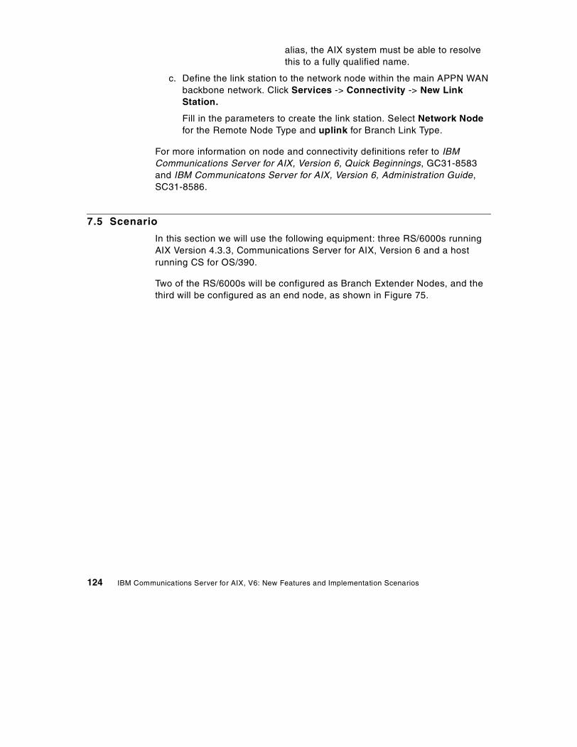
alias, the AIX system must be able to resolvethis to a fully qualified name.
c. Define the link station to the network node within the main APPN WANbackbone network. Click Services -> Connectivity -> New LinkStation.
Fill in the parameters to create the link station. Select Network Nodefor the Remote Node Type and uplink for Branch Link Type.
For more information on node and connectivity definitions refer to IBMCommunications Server for AIX, Version 6, Quick Beginnings, GC31-8583and IBM Communicatons Server for AIX, Version 6, Administration Guide,SC31-8586.
7.5 Scenario
In this section we will use the following equipment: three RS/6000s runningAIX Version 4.3.3, Communications Server for AIX, Version 6 and a hostrunning CS for OS/390.
Two of the RS/6000s will be configured as Branch Extender Nodes, and thethird will be configured as an end node, as shown in Figure 75.
124 IBM Communications Server for AIX, V6: New Features and Implementation Scenarios
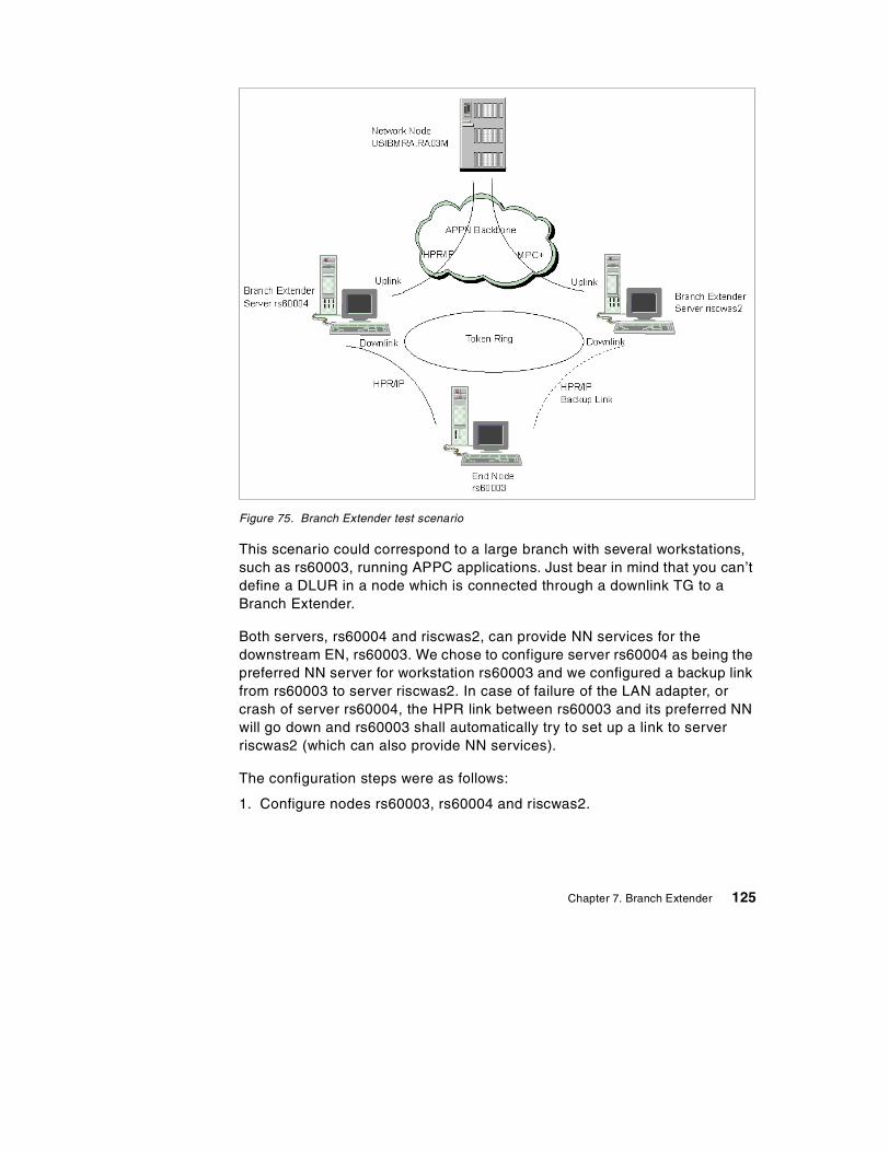
Figure 75. Branch Extender test scenario
This scenario could correspond to a large branch with several workstations,such as rs60003, running APPC applications. Just bear in mind that you can’tdefine a DLUR in a node which is connected through a downlink TG to aBranch Extender.
Both servers, rs60004 and riscwas2, can provide NN services for thedownstream EN, rs60003. We chose to configure server rs60004 as being thepreferred NN server for workstation rs60003 and we configured a backup linkfrom rs60003 to server riscwas2. In case of failure of the LAN adapter, orcrash of server rs60004, the HPR link between rs60003 and its preferred NNwill go down and rs60003 shall automatically try to set up a link to serverriscwas2 (which can also provide NN services).
The configuration steps were as follows:
1. Configure nodes rs60003, rs60004 and riscwas2.
Chapter 7. Branch Extender 125
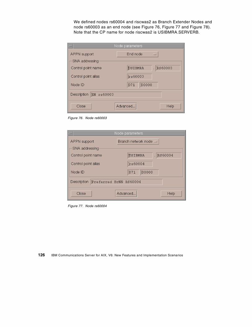
We defined nodes rs60004 and riscwas2 as Branch Extender Nodes andnode rs60003 as an end node (see Figure 76, Figure 77 and Figure 78).Note that the CP name for node riscwas2 is USIBMRA.SERVERB.
Figure 76. Node rs60003
Figure 77. Node rs60004
126 IBM Communications Server for AIX, V6: New Features and Implementation Scenarios
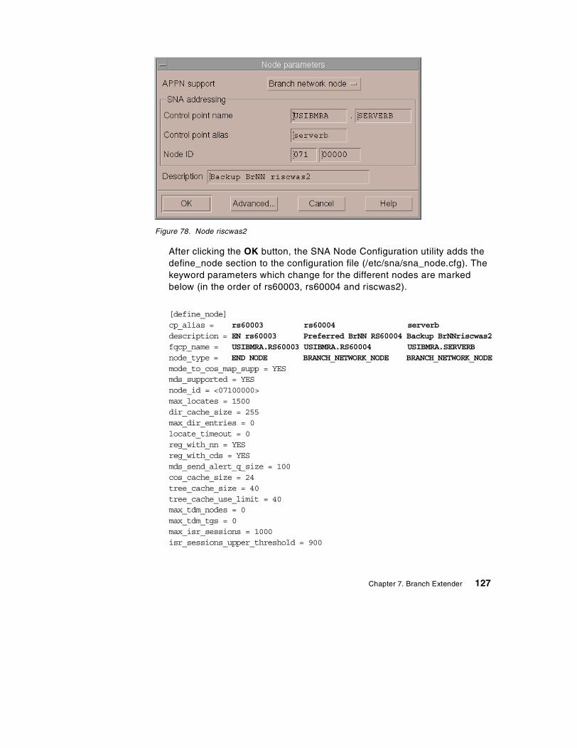
Figure 78. Node riscwas2
After clicking the OK button, the SNA Node Configuration utility adds thedefine_node section to the configuration file (/etc/sna/sna_node.cfg). Thekeyword parameters which change for the different nodes are markedbelow (in the order of rs60003, rs60004 and riscwas2).
[define_node]cp_alias = rs60003 rs60004 serverbdescription = EN rs60003 Preferred BrNN RS60004 Backup BrNNriscwas2fqcp_name = USIBMRA.RS60003 USIBMRA.RS60004 USIBMRA.SERVERBnode_type = END NODE BRANCH_NETWORK_NODE BRANCH_NETWORK_NODEmode_to_cos_map_supp = YESmds_supported = YESnode_id = <07100000>max_locates = 1500dir_cache_size = 255max_dir_entries = 0locate_timeout = 0reg_with_nn = YESreg_with_cds = YESmds_send_alert_q_size = 100cos_cache_size = 24tree_cache_size = 40tree_cache_use_limit = 40max_tdm_nodes = 0max_tdm_tgs = 0max_isr_sessions = 1000isr_sessions_upper_threshold = 900
Chapter 7. Branch Extender 127
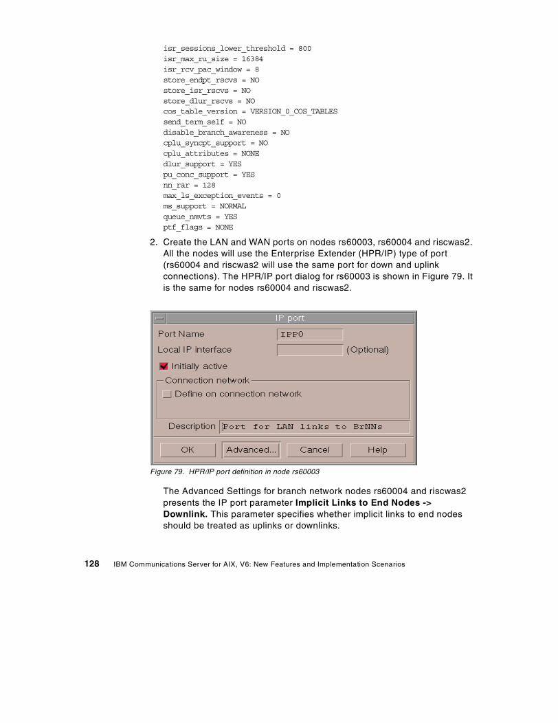
isr_sessions_lower_threshold = 800isr_max_ru_size = 16384isr_rcv_pac_window = 8store_endpt_rscvs = NOstore_isr_rscvs = NOstore_dlur_rscvs = NOcos_table_version = VERSION_0_COS_TABLESsend_term_self = NOdisable_branch_awareness = NOcplu_syncpt_support = NOcplu_attributes = NONEdlur_support = YESpu_conc_support = YESnn_rar = 128max_ls_exception_events = 0ms_support = NORMALqueue_nmvts = YESptf_flags = NONE
2. Create the LAN and WAN ports on nodes rs60003, rs60004 and riscwas2.All the nodes will use the Enterprise Extender (HPR/IP) type of port(rs60004 and riscwas2 will use the same port for down and uplinkconnections). The HPR/IP port dialog for rs60003 is shown in Figure 79. Itis the same for nodes rs60004 and riscwas2.
Figure 79. HPR/IP port definition in node rs60003
The Advanced Settings for branch network nodes rs60004 and riscwas2presents the IP port parameter Implicit Links to End Nodes ->Downlink. This parameter specifies whether implicit links to end nodesshould be treated as uplinks or downlinks.
128 IBM Communications Server for AIX, V6: New Features and Implementation Scenarios
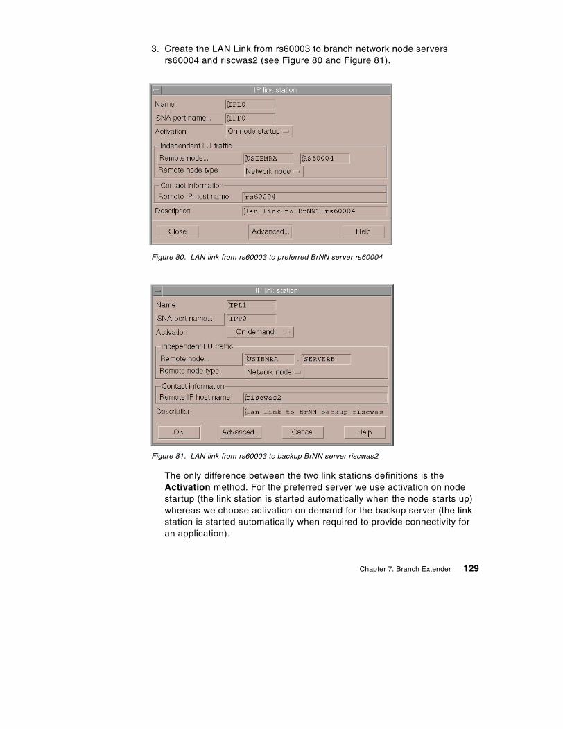
3. Create the LAN Link from rs60003 to branch network node serversrs60004 and riscwas2 (see Figure 80 and Figure 81).
Figure 80. LAN link from rs60003 to preferred BrNN server rs60004
Figure 81. LAN link from rs60003 to backup BrNN server riscwas2
The only difference between the two link stations definitions is theActivation method. For the preferred server we use activation on nodestartup (the link station is started automatically when the node starts up)whereas we choose activation on demand for the backup server (the linkstation is started automatically when required to provide connectivity foran application).
Chapter 7. Branch Extender 129
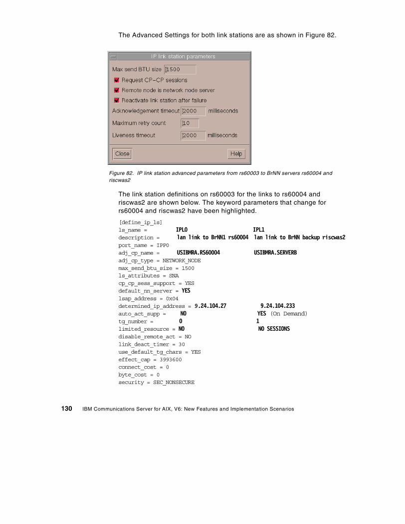
The Advanced Settings for both link stations are as shown in Figure 82.
Figure 82. IP link station advanced parameters from rs60003 to BrNN servers rs60004 andriscwas2
The link station definitions on rs60003 for the links to rs60004 andriscwas2 are shown below. The keyword parameters that change forrs60004 and riscwas2 have been highlighted.
[define_ip_ls]ls_name = IPL0 IPL1description = lan link to BrNN1 rs60004 lan link to BrNN backup riscwas2port_name = IPP0adj_cp_name = USIBMRA.RS60004 USIBMRA.SERVERBadj_cp_type = NETWORK_NODEmax_send_btu_size = 1500ls_attributes = SNAcp_cp_sess_support = YESdefault_nn_server = YESlsap_address = 0x04determined_ip_address = 9.24.104.27 9.24.104.233auto_act_supp = NO YES (On Demand)tg_number = 0 1limited_resource = NO NO SESSIONSdisable_remote_act = NOlink_deact_timer = 30use_default_tg_chars = YESeffect_cap = 3993600connect_cost = 0byte_cost = 0security = SEC_NONSECURE
130 IBM Communications Server for AIX, V6: New Features and Implementation Scenarios
prop_delay = PROP_DELAY_LANuser_def_parm_1 = 128user_def_parm_2 = 128user_def_parm_3 = 128target_pacing_count = 7max_ifrm_rcvd = 0branch_link_type = NONEadj_brnn_cp_support = ALLOWEDinitially_active = YES NOrestart_on_normal_deact = NOreact_timer = 30react_timer_retry = 65535remote_ip_host = rs60004 riscwas2 ack_timeout = 2000max_retry = 10liveness_timeout = 2000short_hold_mode = NO
Note: For an end node, the parameter default_nn_server specifieswhether this is a link supporting CP-CP sessions to a network node thatcan act as the local node's network node server. When the local node hasno CP-CP sessions to a network node server and needs to establish them,it checks this parameter on its defined link stations to find a suitable linkstation to activate. This enables you to specify which adjacent NNs aresuitable to act as the NN server. Possible values are:
- YES: This link supports CP-CP sessions to a network node that can actas the local node's NN server; the local node can automatically activatethis link if it needs to contact an NN server. The cp_cp_sess_supportparameter must be set to YES.
- NO: This link does not support CP-CP sessions to a network node thatcan act as the local node's NN server; the local node cannotautomatically activate this link if it needs to contact an NN server.
If the local node is not an end node, this parameter is ignored.
4. Create the LAN links from the server nodes rs60004 and riscwas2 to theend node rs60003. The configuration parameters are the same for bothnodes; see Figure 83 and Figure 84.
Chapter 7. Branch Extender 131
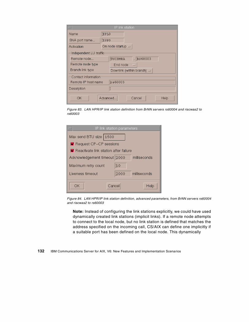
Figure 83. LAN HPR/IP link station definition from BrNN servers rs60004 and riscwas2 tors60003
Figure 84. LAN HPR/IP link station definition, advanced parameters, from BrNN servers rs60004and riscwas2 to rs60003
Note: Instead of configuring the link stations explicitly, we could have useddynamically created link stations (implicit links). If a remote node attemptsto connect to the local node, but no link station is defined that matches theaddress specified on the incoming call, CS/AIX can define one implicitly ifa suitable port has been defined on the local node. This dynamically
132 IBM Communications Server for AIX, V6: New Features and Implementation Scenarios

created link station appears in the connectivity section of the Node windowfor the duration of the connection.
The define_ip_ls section in the configuration file /etc/sna/sna_node.cfg isthe same for rs60004 and riscwas2. It looks like:
[define_ip_ls]ls_name = IPL0description = ““port_name = IPP0adj_cp_name = USIBMRA.RS60003adj_cp_type = END_NODEmax_send_btu_size = 1500ls_attributes = SNAcp_cp_sess_support = YESdefault_nn_server = NOlsap_address = 0x04determined_ip_address = 9.24.104.23auto_act_supp = NOtg_number = 0limited_resource = NOdisable_remote_act = NOlink_deact_timer = 30use_default_tg_chars = YESeffect_cap = 3993600connect_cost = 0byte_cost = 0security = SEC_NONSECUREprop_delay = PROP_DELAY_LANuser_def_parm_1 = 128user_def_parm_2 = 128user_def_parm_3 = 128target_pacing_count = 7max_ifrm_rcvd = 0branch_link_type = DOWNLINKadj_brnn_cp_support = ALLOWEDinitially_active = YESrestart_on_normal_deact = NOreact_timer = 30react_timer_retry = 65535remote_ip_host = rs60003ack_timeout = 2000max_retry = 10liveness_timeout = 2000short_hold_mode = NO
5. Create the WAN links from BrNN servers rs60004 and riscwas2 to thepreferred NN in the WAN APPN Network. We used HPR/IP links in both
Chapter 7. Branch Extender 133
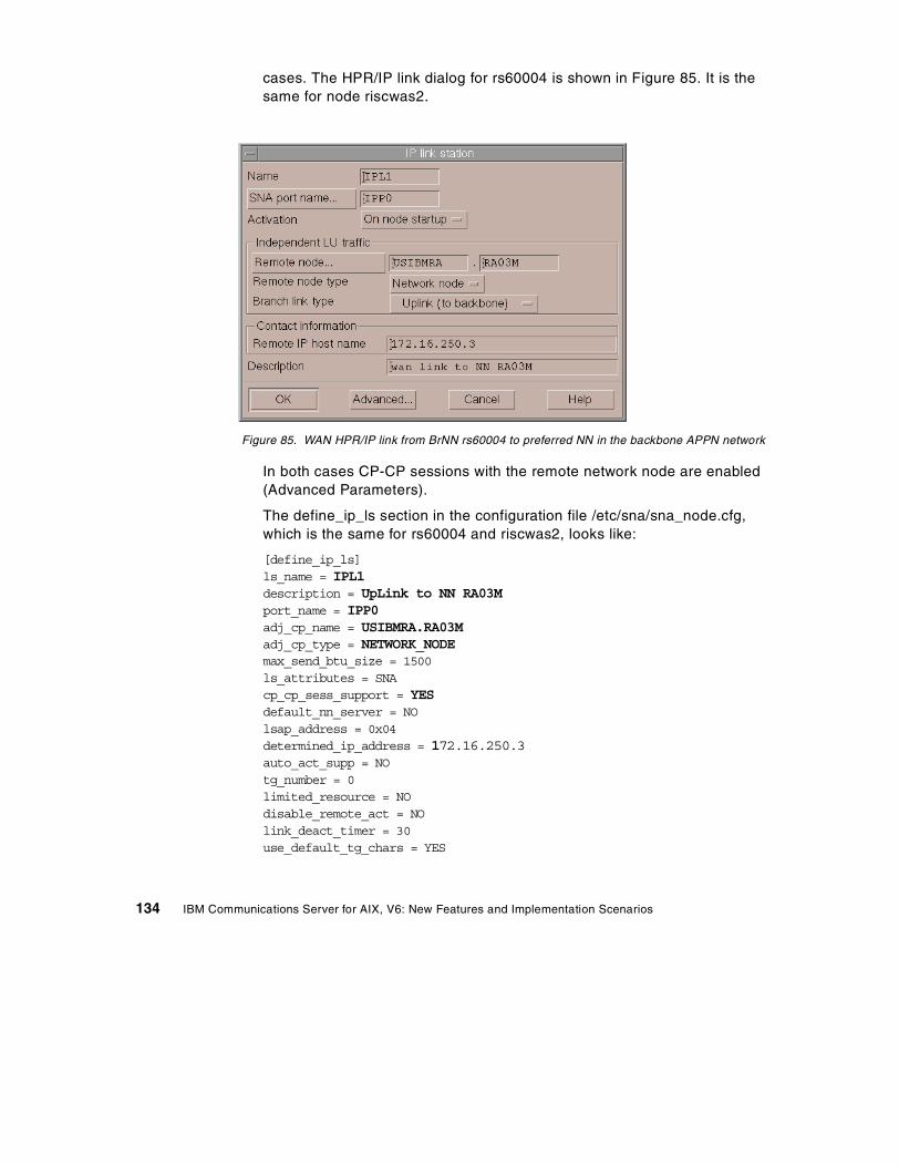
cases. The HPR/IP link dialog for rs60004 is shown in Figure 85. It is thesame for node riscwas2.
Figure 85. WAN HPR/IP link from BrNN rs60004 to preferred NN in the backbone APPN network
In both cases CP-CP sessions with the remote network node are enabled(Advanced Parameters).
The define_ip_ls section in the configuration file /etc/sna/sna_node.cfg,which is the same for rs60004 and riscwas2, looks like:
[define_ip_ls]ls_name = IPL1description = UpLink to NN RA03Mport_name = IPP0adj_cp_name = USIBMRA.RA03Madj_cp_type = NETWORK_NODEmax_send_btu_size = 1500ls_attributes = SNAcp_cp_sess_support = YESdefault_nn_server = NOlsap_address = 0x04determined_ip_address = 172.16.250.3auto_act_supp = NOtg_number = 0limited_resource = NOdisable_remote_act = NOlink_deact_timer = 30use_default_tg_chars = YES
134 IBM Communications Server for AIX, V6: New Features and Implementation Scenarios
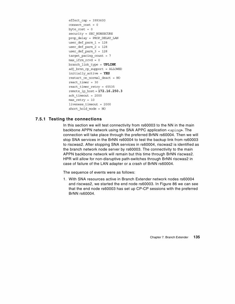
effect_cap = 3993600connect_cost = 0byte_cost = 0security = SEC_NONSECUREprop_delay = PROP_DELAY_LANuser_def_parm_1 = 128user_def_parm_2 = 128user_def_parm_3 = 128target_pacing_count = 7max_ifrm_rcvd = 0branch_link_type = UPLINKadj_brnn_cp_support = ALLOWEDinitially_active = YESrestart_on_normal_deact = NOreact_timer = 30react_timer_retry = 65535remote_ip_host = 172.16.250.3ack_timeout = 2000max_retry = 10liveness_timeout = 2000short_hold_mode = NO
7.5.1 Testing the connectionsIn this section we will test connectivity from rs60003 to the NN in the mainbackbone APPN network using the SNA APPC application <aping>. Theconnection will take place through the preferred BrNN rs60004. Then we willstop SNA services in the BrNN rs60004 to test the backup link from rs60003to riscwas2. After stopping SNA services in rs60004, riscwas2 is identified asthe branch network node server by rs60003. The connectivity to the mainAPPN backbone network will remain but this time through BrNN riscwas2.HPR will allow for non-disruptive path-switches through BrNN riscwas2 incase of failure of the LAN adapter or a crash of BrNN rs60004.
The sequence of events were as follows:
1. With SNA resources active in Branch Extender network nodes rs60004and riscwas2, we started the end node rs60003. In Figure 86 we can seethat the end node rs60003 has set up CP-CP sessions with the preferredBrNN rs60004.
Chapter 7. Branch Extender 135
Figure 86. rs60003 node window after activation
2. We tested connectivity from the end node rs60003 to the main APPNbackbone network using the SNA APPC application <aping>. Figure 87 onpage 137 shows the establishment of the RTP connections betweenrs60003 and the network node in the main APPN backbone network. TheRTP connection with COS SNASVCMG is established to perform a CNOS(Change Number of Sessions) for mode #INTER, after which the RTPconnection that carries the actual #INTER session (aping session) isstarted.
136 IBM Communications Server for AIX, V6: New Features and Implementation Scenarios
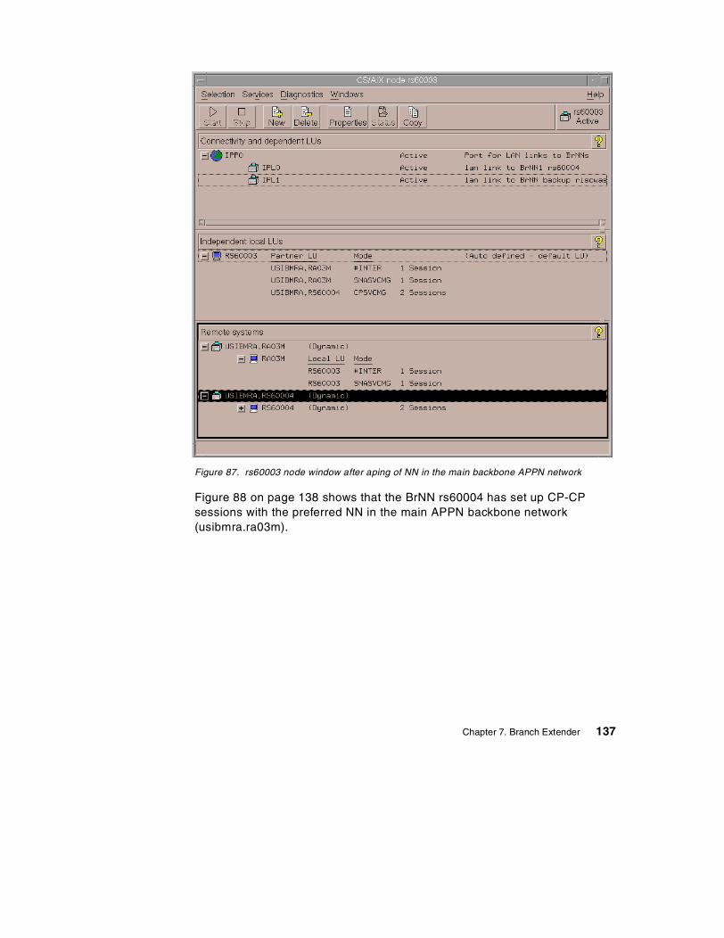
Figure 87. rs60003 node window after aping of NN in the main backbone APPN network
Figure 88 on page 138 shows that the BrNN rs60004 has set up CP-CPsessions with the preferred NN in the main APPN backbone network(usibmra.ra03m).
Chapter 7. Branch Extender 137
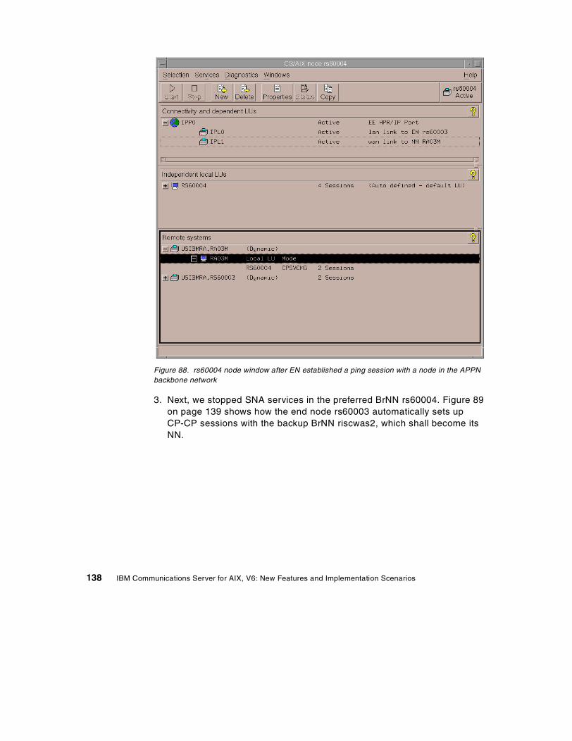
Figure 88. rs60004 node window after EN established a ping session with a node in the APPNbackbone network
3. Next, we stopped SNA services in the preferred BrNN rs60004. Figure 89on page 139 shows how the end node rs60003 automatically sets upCP-CP sessions with the backup BrNN riscwas2, which shall become itsNN.
138 IBM Communications Server for AIX, V6: New Features and Implementation Scenarios
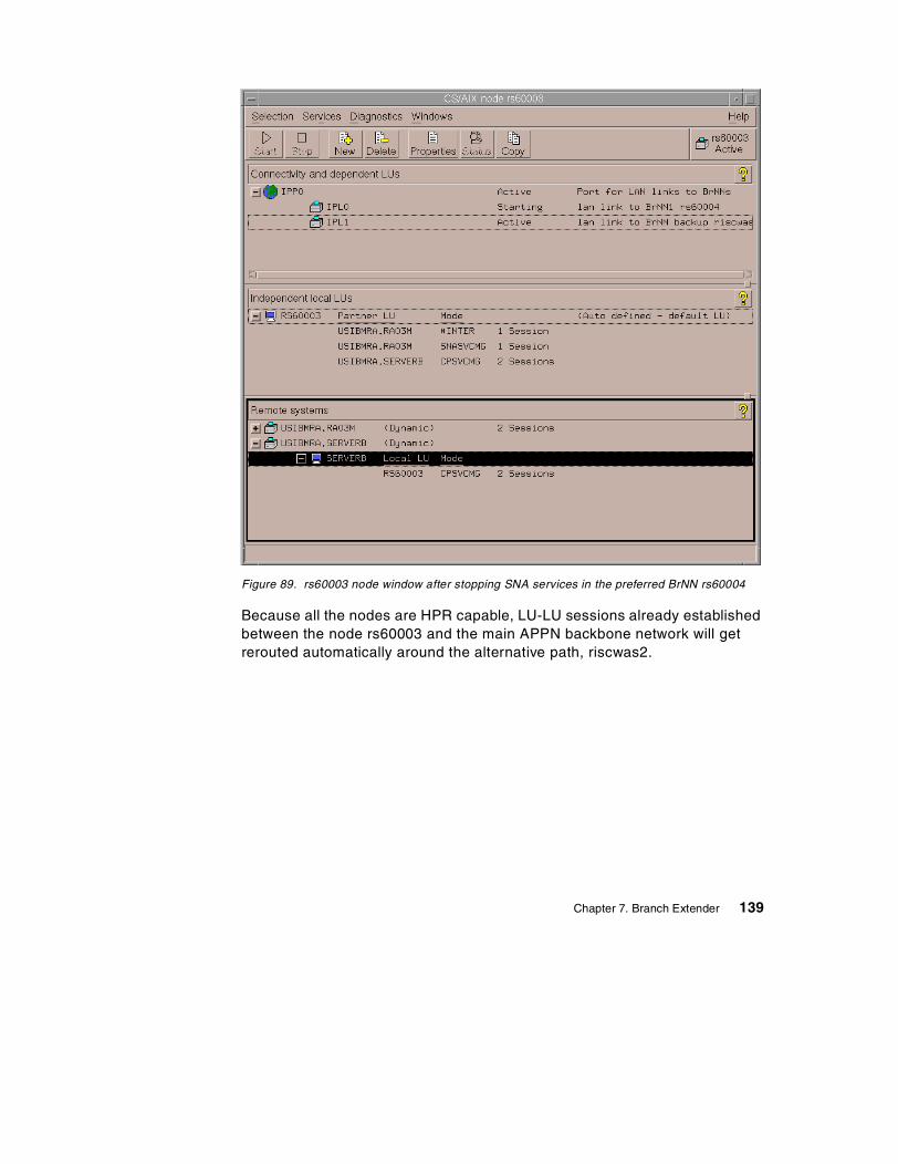
Figure 89. rs60003 node window after stopping SNA services in the preferred BrNN rs60004
Because all the nodes are HPR capable, LU-LU sessions already establishedbetween the node rs60003 and the main APPN backbone network will getrerouted automatically around the alternative path, riscwas2.
Chapter 7. Branch Extender 139

140 IBM Communications Server for AIX, V6: New Features and Implementation Scenarios
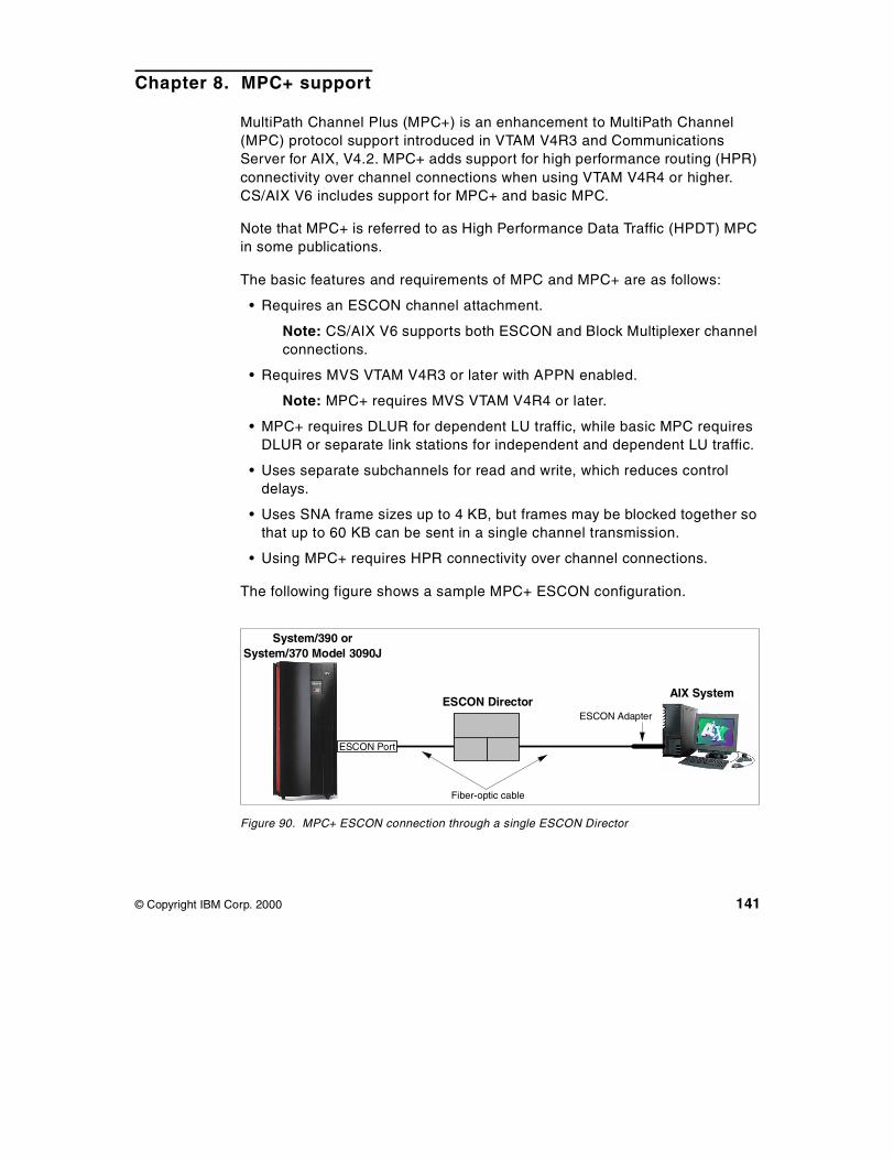
Chapter 8. MPC+ support
MultiPath Channel Plus (MPC+) is an enhancement to MultiPath Channel(MPC) protocol support introduced in VTAM V4R3 and CommunicationsServer for AIX, V4.2. MPC+ adds support for high performance routing (HPR)connectivity over channel connections when using VTAM V4R4 or higher.CS/AIX V6 includes support for MPC+ and basic MPC.
Note that MPC+ is referred to as High Performance Data Traffic (HPDT) MPCin some publications.
The basic features and requirements of MPC and MPC+ are as follows:
• Requires an ESCON channel attachment.
Note: CS/AIX V6 supports both ESCON and Block Multiplexer channelconnections.
• Requires MVS VTAM V4R3 or later with APPN enabled.
Note: MPC+ requires MVS VTAM V4R4 or later.
• MPC+ requires DLUR for dependent LU traffic, while basic MPC requiresDLUR or separate link stations for independent and dependent LU traffic.
• Uses separate subchannels for read and write, which reduces controldelays.
• Uses SNA frame sizes up to 4 KB, but frames may be blocked together sothat up to 60 KB can be sent in a single channel transmission.
• Using MPC+ requires HPR connectivity over channel connections.
The following figure shows a sample MPC+ ESCON configuration.
Figure 90. MPC+ ESCON connection through a single ESCON Director
System/390 orSystem/370 Model 3090J
ESCON Director
ESCON Port
ESCON Adapter
AIX System
Fiber-optic cable
© Copyright IBM Corp. 2000 141
The previous figure shows an ESCON director between the host and the AIXsystem. However, an ESCON director is not required. Up to two ESCONdirectors may be used to extend the distance between the host and AIXsystem up to 43 kilometers.
MPC+ links require HPR and support only independent LUs. Therefore, ifdependent LU (LU0, 1, 2, 3) support is required over an MPC+ link,DLUR/DLUS must be used.
The overall CS/AIX support for channel connectivity is referred to as the SNAChannel for AIX feature. Support for MPC+ connectivity is part of the SNAChannel for AIX feature. See the IBM Communications Server for AIXChannel Connectivity User’s Guide, SC31-8219 for detailed information on allthe channel connectivity options supported by CS/AIX V6.
8.1 Hardware requirements
The SNA Channel for AIX feature of CS/AIX V6 supports both Micro ChannelArchitecture (MCA) ESCON and Peripheral Component Interconnect (PCI)ESCON adapter cards. In this book, we cover only the PCI ESCON adapterconfiguration.
To install SNA Channel for AIX for the PCI ESCON adapter, you must havethe following hardware:
• S/390 ESCON Channel PCI Adapter (Feature 2751)
• ESCON fiber optic cabling and connections
• One of the following RISC System/6000 models:
- 7017, all models
- 7025 Models F50 and F80
- 7026 Models H50, H70, H80 and M80
• One of the following host systems:
- IBM ES/9000 Model 9021
- IBM 9672
8.2 Software requirements
To install SNA Channel for AIX for the PCI ESCON adapter, you must havethe following software:
142 IBM Communications Server for AIX, V6: New Features and Implementation Scenarios
• S/390 ESCON Channel PCI Adapter device driver (program number5765-D49)
• AIX 4.3.2 or later
• IBM Communications Server for AIX, V6 or later
• MVS VTAM V4R3 or higher, with APPN enabled
Note: For MPC+ support, VTAM V4R4 or later is required.
In addition, CS/AIX includes the following data link control filesets to supportSNA channel data link communications:
sna.dlcchannel Contains the SNA Channel for AIX SNA DLC software forCDLC mode channel communications
sna.dlcmpc Contains the SNA Channel for AIX SNA DLC software forMPC mode channel communications
Both of these filesets are included as part of the SNA Channel for AIX featureof CS/AIX.
For MPC+ channel communications, the sna.dlcmpc fileset is required andshould be installed when CS/AIX is installed.
8.3 MPC+ configuration
Configuration of MPC+ support for a ESCON PCI adapter involves hardwareinstallation on the AIX system and software definitions on both the MVS hostand AIX systems. The software definitions must be closely coordinatedbetween the two systems.
The following figure gives an overview of where software definitions arerequired. Arrows indicate where definition statements refer to parameterscoded on other definition statements within that system.
Chapter 8. MPC+ support 143
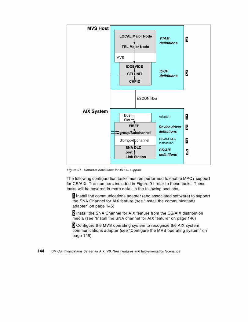
Figure 91. Software definitions for MPC+ support
The following configuration tasks must be performed to enable MPC+ supportfor CS/AIX. The numbers included in Figure 91 refer to these tasks. Thesetasks will be covered in more detail in the following sections.
1 Install the communications adapter (and associated software) to supportthe SNA Channel for AIX feature (see “Install the communicationsadapter” on page 145)
2 Install the SNA Channel for AIX feature from the CS/AIX distributionmedia (see “Install the SNA channel for AIX feature” on page 146)
3 Configure the MVS operating system to recognize the AIX systemcommunications adapter (see “Configure the MVS operating system” onpage 146)
MVS Host
AIX System
VTAMdefinitions
IOCPdefinitions
MVS
Device driverdefinitions
CS/AIXdefinitions
CS/AIX DLCinstallation
TRL Major Node
LOCAL Major Node
IODEVICE
CTLUNIT
CHPID
BusSlot
FIBER
group/Subchannel
dlcmpc/dlcchannel
SNA DLCportLink Station
ESCON fiber
Adapter 1
2
3
5
6
4
144 IBM Communications Server for AIX, V6: New Features and Implementation Scenarios
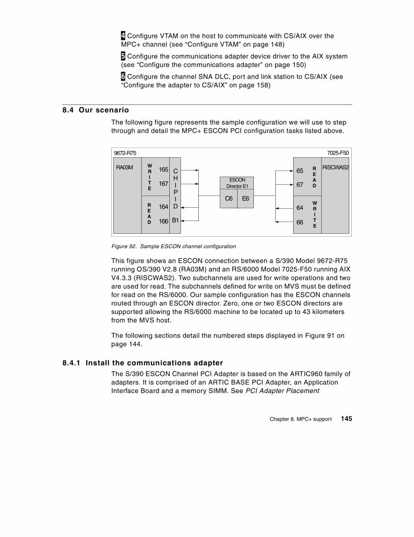
4 Configure VTAM on the host to communicate with CS/AIX over theMPC+ channel (see “Configure VTAM” on page 148)
5 Configure the communications adapter device driver to the AIX system(see “Configure the communications adapter” on page 150)
6 Configure the channel SNA DLC, port and link station to CS/AIX (see“Configure the adapter to CS/AIX” on page 158)
8.4 Our scenario
The following figure represents the sample configuration we will use to stepthrough and detail the MPC+ ESCON PCI configuration tasks listed above.
Figure 92. Sample ESCON channel configuration
This figure shows an ESCON connection between a S/390 Model 9672-R75running OS/390 V2.8 (RA03M) and an RS/6000 Model 7025-F50 running AIXV4.3.3 (RISCWAS2). Two subchannels are used for write operations and twoare used for read. The subchannels defined for write on MVS must be definedfor read on the RS/6000. Our sample configuration has the ESCON channelsrouted through an ESCON director. Zero, one or two ESCON directors aresupported allowing the RS/6000 machine to be located up to 43 kilometersfrom the MVS host.
The following sections detail the numbered steps displayed in Figure 91 onpage 144.
8.4.1 Install the communications adapterThe S/390 ESCON Channel PCI Adapter is based on the ARTIC960 family ofadapters. It is comprised of an ARTIC BASE PCI Adapter, an ApplicationInterface Board and a memory SIMM. See PCI Adapter Placement
RA03M WRITE
READ
READ
WRITE
165
167
164
166
65
67
64
66
C6 E6
9672-R75 7025-F50
RISCWAS2
ESCONDirector E1
CHIPID
B1
Chapter 8. MPC+ support 145
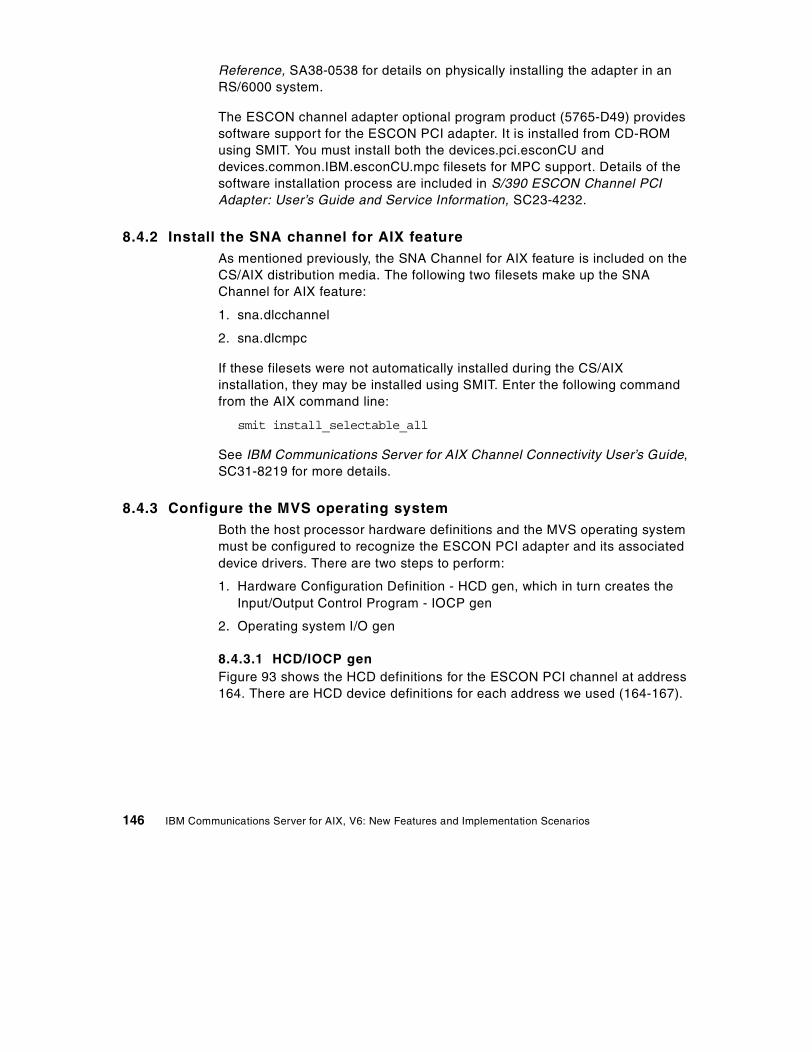
Reference, SA38-0538 for details on physically installing the adapter in anRS/6000 system.
The ESCON channel adapter optional program product (5765-D49) providessoftware support for the ESCON PCI adapter. It is installed from CD-ROMusing SMIT. You must install both the devices.pci.esconCU anddevices.common.IBM.esconCU.mpc filesets for MPC support. Details of thesoftware installation process are included in S/390 ESCON Channel PCIAdapter: User’s Guide and Service Information, SC23-4232.
8.4.2 Install the SNA channel for AIX featureAs mentioned previously, the SNA Channel for AIX feature is included on theCS/AIX distribution media. The following two filesets make up the SNAChannel for AIX feature:
1. sna.dlcchannel
2. sna.dlcmpc
If these filesets were not automatically installed during the CS/AIXinstallation, they may be installed using SMIT. Enter the following commandfrom the AIX command line:
smit install_selectable_all
See IBM Communications Server for AIX Channel Connectivity User’s Guide,SC31-8219 for more details.
8.4.3 Configure the MVS operating systemBoth the host processor hardware definitions and the MVS operating systemmust be configured to recognize the ESCON PCI adapter and its associateddevice drivers. There are two steps to perform:
1. Hardware Configuration Definition - HCD gen, which in turn creates theInput/Output Control Program - IOCP gen
2. Operating system I/O gen
8.4.3.1 HCD/IOCP genFigure 93 shows the HCD definitions for the ESCON PCI channel at address164. There are HCD device definitions for each address we used (164-167).
146 IBM Communications Server for AIX, V6: New Features and Implementation Scenarios
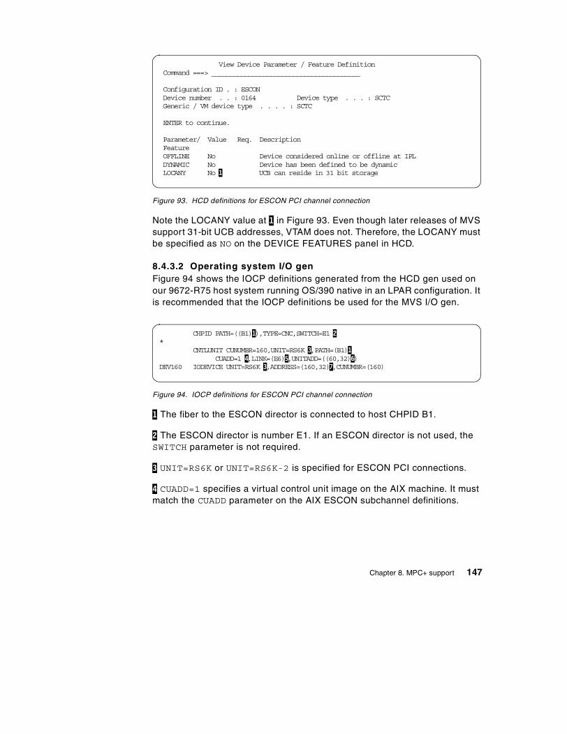
Figure 93. HCD definitions for ESCON PCI channel connection
Note the LOCANY value at 1 in Figure 93. Even though later releases of MVSsupport 31-bit UCB addresses, VTAM does not. Therefore, the LOCANY mustbe specified as NO on the DEVICE FEATURES panel in HCD.
8.4.3.2 Operating system I/O genFigure 94 shows the IOCP definitions generated from the HCD gen used onour 9672-R75 host system running OS/390 native in an LPAR configuration. Itis recommended that the IOCP definitions be used for the MVS I/O gen.
Figure 94. IOCP definitions for ESCON PCI channel connection
1 The fiber to the ESCON director is connected to host CHPID B1.
2 The ESCON director is number E1. If an ESCON director is not used, theSWITCH parameter is not required.
3 UNIT=RS6K or UNIT=RS6K-2 is specified for ESCON PCI connections.
4 CUADD=1 specifies a virtual control unit image on the AIX machine. It mustmatch the CUADD parameter on the AIX ESCON subchannel definitions.
View Device Parameter / Feature DefinitionCommand ===> ________________________________________
Configuration ID . : ESCONDevice number . . : 0164 Device type . . . : SCTCGeneric / VM device type . . . . : SCTC
ENTER to continue.
Parameter/ Value Req. DescriptionFeatureOFFLINE No Device considered online or offline at IPLDYNAMIC No Device has been defined to be dynamicLOCANY No 1 UCB can reside in 31 bit storage
CHPID PATH=((B1)1),TYPE=CNC,SWITCH=E1 2*
CNTLUNIT CUNUMBR=160,UNIT=RS6K 3,PATH=(B1)1CUADD=1 4,LINK=(E6)5,UNITADD=((60,32)6)
DEV160 IODEVICE UNIT=RS6K 3,ADDRESS=(160,32)7,CUNUMBR=(160)
Chapter 8. MPC+ support 147
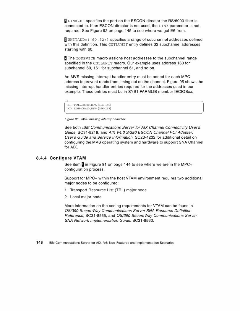
5 LINK=E6 specifies the port on the ESCON director the RS/6000 fiber isconnected to. If an ESCON director is not used, the LINK parameter is notrequired. See Figure 92 on page 145 to see where we got E6 from.
6 UNITADD=((60,32)) specifies a range of subchannel addresses definedwith this definition. This CNTLUNIT entry defines 32 subchannel addressesstarting with 60.
7 The IODEVICE macro assigns host addresses to the subchannel rangespecified in the CNTLUNIT macro. Our example uses address 160 forsubchannel 60, 161 for subchannel 61, and so on.
An MVS missing interrupt handler entry must be added for each MPCaddress to prevent reads from timing out on the channel. Figure 95 shows themissing interrupt handler entries required for the addresses used in ourexample. These entries must be in SYS1.PARMLIB member IECIOSxx.
Figure 95. MVS missing interrupt handler
See both IBM Communications Server for AIX Channel Connectivity User’sGuide, SC31-8219, and AIX V4.3 S/390 ESCON Channel PCI Adapter:User’s Guide and Service Information, SC23-4232 for additional detail onconfiguring the MVS operating system and hardware to support SNA Channelfor AIX.
8.4.4 Configure VTAMSee item 4 in Figure 91 on page 144 to see where we are in the MPC+configuration process.
Support for MPC+ within the host VTAM environment requires two additionalmajor nodes to be configured:
1. Transport Resource List (TRL) major node
2. Local major node
More information on the coding requirements for VTAM can be found inOS/390 SecureWay Communications Server SNA Resource DefinitionReference, SC31-8565, and OS/390 SecureWay Communications ServerSNA Network Implementation Guide, SC31-8563.
MIH TIME=00:00,DEV=(164-165)MIH TIME=00:00,DEV=(166-167)
148 IBM Communications Server for AIX, V6: New Features and Implementation Scenarios
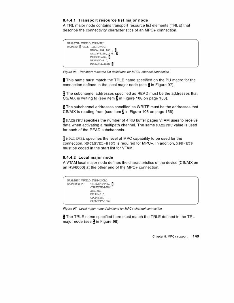
8.4.4.1 Transport resource list major nodeA TRL major node contains transport resource list elements (TRLE) thatdescribe the connectivity characteristics of an MPC+ connection.
Figure 96. Transport resource list definitions for MPC+ channel connection
1 This name must match the TRLE name specified on the PU macro for theconnection defined in the local major node (see 1 in Figure 97).
2 The subchannel addresses specified as READ must be the addresses thatCS/AIX is writing to (see item 3 in Figure 108 on page 156).
3 The subchannel addresses specified as WRITE must be the addresses thatCS/AIX is reading from (see item 2 in Figure 108 on page 156).
4 MAXBFRU specifies the number of 4 KB buffer pages VTAM uses to receivedata when activating a multipath channel. The same MAXBFRU value is usedfor each of the READ subchannels.
5 MPCLEVEL specifies the level of MPC capability to be used for theconnection. MPCLEVEL=HPDT is required for MPC+. In addition, HPR=RTPmust be coded in the start list for VTAM.
8.4.4.2 Local major nodeA VTAM local major node defines the characteristics of the device (CS/AIX onan RS/6000) at the other end of the MPC+ connection.
Figure 97. Local major node definitions for MPC+ channel connection
1 The TRLE name specified here must match the TRLE defined in the TRLmajor node (see 1 in Figure 96).
RA3R6TRL VBUILD TYPE=TRLRA3MPCA 1 TRLE LNCTL=MPC,
READ=(164,166), 2WRITE=(165,167), 3MAXBFRU=16, 4REPLYTO=3.0,MPCLEVEL=HPDT 5
RA3R6MPC VBUILD TYPE=LOCALRA3MPCPU PU TRLE=RA3MPCA, 1
CONNTYPE=APPN,XID=YES,DELAY=0.0,CPCP=YES,CAPACITY=136M
Chapter 8. MPC+ support 149
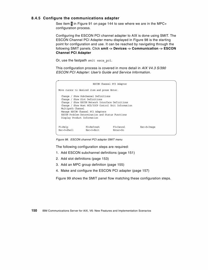
8.4.5 Configure the communications adapterSee item 5 in Figure 91 on page 144 to see where we are in the MPC+configuration process.
Configuring the ESCON PCI channel adapter to AIX is done using SMIT. TheESCON Channel PCI Adapter menu displayed in Figure 98 is the startingpoint for configuration and use. It can be reached by navigating through thefollowing SMIT panels. Click smit -> Devices -> Communication -> ESCONChannel PCI Adapter
Or, use the fastpath smit esca_pci.
This configuration process is covered in more detail in AIX V4.3 S/390ESCON PCI Adapter: User’s Guide and Service Information.
Figure 98. ESCON channel PCI adapter SMIT menu
The following configuration steps are required:
1. Add ESCON subchannel definitions (page 151)
2. Add slot definitions (page 153)
3. Add an MPC group definition (page 155)
4. Make and configure the ESCON PCI adapter (page 157)
Figure 99 shows the SMIT panel flow matching these configuration steps.
ESCON Channel PCI Adapter
Move cursor to desired item and press Enter.
Change / Show Subchannel DefinitionsChange / Show Slot DefinitionsChange / Show ESCON Network Interface DefinitionsChange / Show Host HCD/IOCP Control Unit InformationMultipath ChannelManage ESCON Channel PCI AdaptersESCON Problem Determination and Status FunctionsDisplay Product Information
F1=Help F2=Refresh F3=Cancel Esc+8=ImageEsc+9=Shell Esc+0=Exit Enter=Do
150 IBM Communications Server for AIX, V6: New Features and Implementation Scenarios
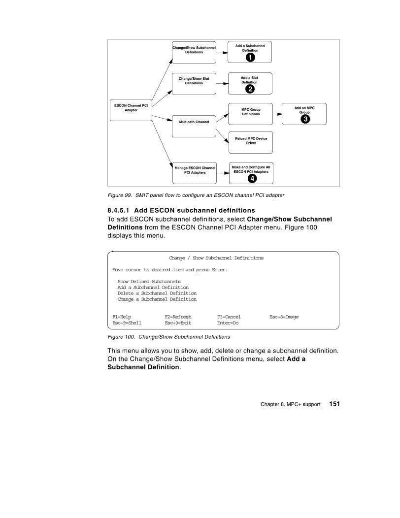
Figure 99. SMIT panel flow to configure an ESCON channel PCI adapter
8.4.5.1 Add ESCON subchannel definitionsTo add ESCON subchannel definitions, select Change/Show SubchannelDefinitions from the ESCON Channel PCI Adapter menu. Figure 100displays this menu.
Figure 100. Change/Show Subchannel Definitions
This menu allows you to show, add, delete or change a subchannel definition.On the Change/Show Subchannel Definitions menu, select Add aSubchannel Definition.
ESCON Channel PCIAdapter
Change/Show SubchannelDefinitions
Add a SubchannelDefinition
Change/Show SlotDefinitions
Add a SlotDefinition
Multipath Channel
MPC GroupDefinitions
Reload MPC DeviceDriver
Add an MPCGroup
Manage ESCON ChannelPCI Adapters
Make and Configure AllESCON PCI Adapters
1
2
3
4
Change / Show Subchannel Definitions
Move cursor to desired item and press Enter.
Show Defined SubchannelsAdd a Subchannel DefinitionDelete a Subchannel DefinitionChange a Subchannel Definition
F1=Help F2=Refresh F3=Cancel Esc+8=ImageEsc+9=Shell Esc+0=Exit Enter=Do
Chapter 8. MPC+ support 151
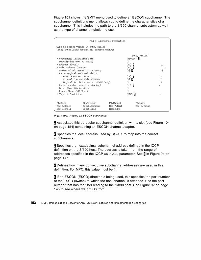
Figure 101 shows the SMIT menu used to define an ESCON subchannel. Thesubchannel definitions menu allows you to define the characteristics of asubchannel. This includes the path to the S/390 channel subsystem as wellas the type of channel emulation to use.
Figure 101. Adding an ESCON subchannel
1 Associates this particular subchannel definition with a slot (see Figure 104on page 154) containing an ESCON channel adapter.
2 Specifies the local address used by CS/AIX to map into the correctsubchannels.
3 Specifies the hexadecimal subchannel address defined in the IOCPdefinition on the S/390 host. The address is taken from the range ofaddresses specified in the IOCP UNITADD parameter. See 6 in Figure 94 onpage 147.
4 Defines how many consecutive subchannel addresses are used in thisdefinition. For MPC, this value must be 1.
5 If an ESCON (ESCD) director is being used, this specifies the port numberof the ESCD (switch) to which the host channel is attached. Use the portnumber that has the fiber leading to the S/390 host. See Figure 92 on page145 to see where we got C6 from.
Add a Subchannel Definition
Type or select values in entry fields.Press Enter AFTER making all desired changes.
[Entry Fields]* Subchannel Definition Name [mpc164] 1Description (max 30 chars) []
* Address (local) [64] 2 X* Unit Address (remote) [64] 3 XNumber of Addresses in the Group [1] 4 #ESCON Logical Path Definition
Host CHPID ESCD Port [c6] 5 XVirtual Control Unit (CUADD) [1] 6 XLogical Partition Number (EMIF Only) [] X
Perform a device-end on startup? [no] 7 +Local Name (Workstation) []Remote Name (390 Host) []
* Type of Emulation [MPC] 8 +
F1=Help F2=Refresh F3=Cancel F4=ListEsc+5=Reset Esc+6=Command Esc+7=Edit Esc+8=ImageEsc+9=Shell Esc+0=Exit Enter=Do
152 IBM Communications Server for AIX, V6: New Features and Implementation Scenarios
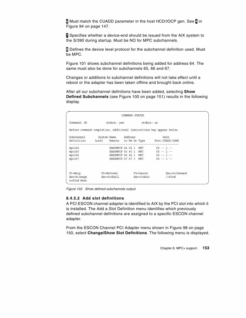
6 Must match the CUADD parameter in the host HCD/IOCP gen. See 4 inFigure 94 on page 147.
7 Specifies whether a device-end should be issued from the AIX system tothe S/390 during startup. Must be NO for MPC subchannels.
8 Defines the device level protocol for the subchannel definition used. Mustbe MPC.
Figure 101 shows subchannel definitions being added for address 64. Thesame must also be done for subchannels 65, 66 and 67.
Changes or additions to subchannel definitions will not take effect until areboot or the adapter has been taken offline and brought back online.
After all our subchannel definitions have been added, selecting ShowDefined Subchannels (see Figure 100 on page 151) results in the followingdisplay.
Figure 102. Show defined subchannels output
8.4.5.2 Add slot definitionsA PCI ESCON channel adapter is identified to AIX by the PCI slot into which itis installed. The Add a Slot Definition menu identifies which previouslydefined subchannel definitions are assigned to a specific ESCON channeladapter.
From the ESCON Channel PCI Adapter menu shown in Figure 98 on page150, select Change/Show Slot Definitions. The following menu is displayed.
COMMAND STATUS
Command: OK stdout: yes stderr: no
Before command completion, additional instructions may appear below.
Subchannel System Name Address PathDefinition Local Remote Lc Rm Gr Type Port-CUADD-LPAR--------------------------------------------------------------------mpc164 RAK6MPCP 64 64 1 MPC C6 -- 1 --mpc165 RAK6MPCP 65 65 1 MPC C6 -- 1 --mpc166 RAK6MPCP 66 66 1 MPC C6 -- 1 --mpc167 RAK6MPCP 67 67 1 MPC C6 -- 1 --
F1=Help F2=Refresh F3=Cancel Esc+6=CommandEsc+8=Image Esc+9=Shell Esc+0=Exit /=Findn=Find Next
Chapter 8. MPC+ support 153
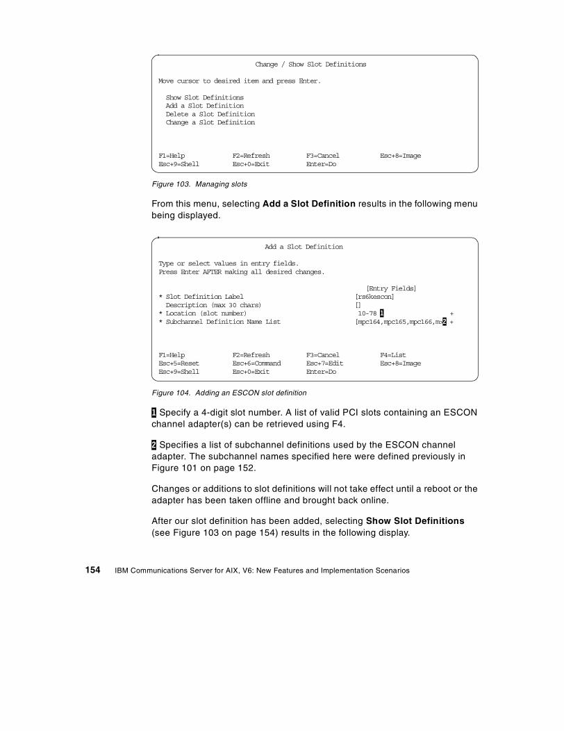
Figure 103. Managing slots
From this menu, selecting Add a Slot Definition results in the following menubeing displayed.
Figure 104. Adding an ESCON slot definition
1 Specify a 4-digit slot number. A list of valid PCI slots containing an ESCONchannel adapter(s) can be retrieved using F4.
2 Specifies a list of subchannel definitions used by the ESCON channeladapter. The subchannel names specified here were defined previously inFigure 101 on page 152.
Changes or additions to slot definitions will not take effect until a reboot or theadapter has been taken offline and brought back online.
After our slot definition has been added, selecting Show Slot Definitions(see Figure 103 on page 154) results in the following display.
Change / Show Slot Definitions
Move cursor to desired item and press Enter.
Show Slot DefinitionsAdd a Slot DefinitionDelete a Slot DefinitionChange a Slot Definition
F1=Help F2=Refresh F3=Cancel Esc+8=ImageEsc+9=Shell Esc+0=Exit Enter=Do
Add a Slot Definition
Type or select values in entry fields.Press Enter AFTER making all desired changes.
[Entry Fields]* Slot Definition Label [rs6kescon]Description (max 30 chars) []
* Location (slot number) 10-78 1 +* Subchannel Definition Name List [mpc164,mpc165,mpc166,m>2 +
F1=Help F2=Refresh F3=Cancel F4=ListEsc+5=Reset Esc+6=Command Esc+7=Edit Esc+8=ImageEsc+9=Shell Esc+0=Exit Enter=Do
154 IBM Communications Server for AIX, V6: New Features and Implementation Scenarios
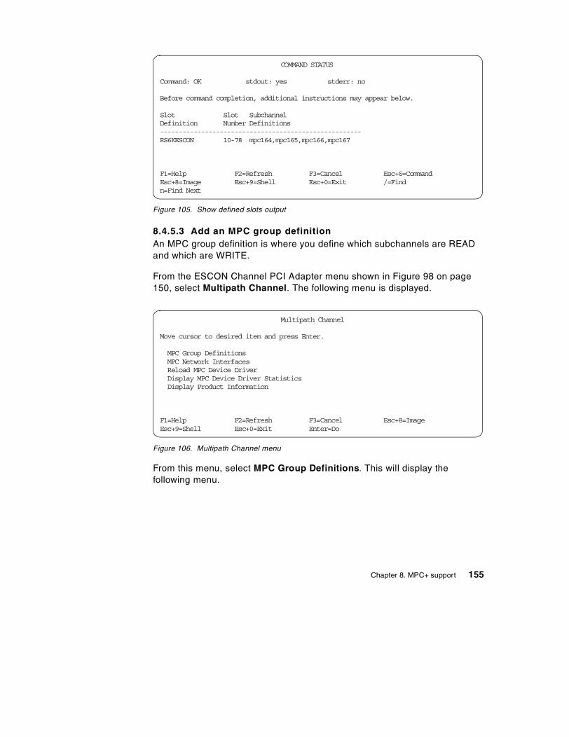
Figure 105. Show defined slots output
8.4.5.3 Add an MPC group definitionAn MPC group definition is where you define which subchannels are READand which are WRITE.
From the ESCON Channel PCI Adapter menu shown in Figure 98 on page150, select Multipath Channel. The following menu is displayed.
Figure 106. Multipath Channel menu
From this menu, select MPC Group Definitions. This will display thefollowing menu.
COMMAND STATUS
Command: OK stdout: yes stderr: no
Before command completion, additional instructions may appear below.
Slot Slot SubchannelDefinition Number Definitions------------------------------------------------------RS6KESCON 10-78 mpc164,mpc165,mpc166,mpc167
F1=Help F2=Refresh F3=Cancel Esc+6=CommandEsc+8=Image Esc+9=Shell Esc+0=Exit /=Findn=Find Next
Multipath Channel
Move cursor to desired item and press Enter.
MPC Group DefinitionsMPC Network InterfacesReload MPC Device DriverDisplay MPC Device Driver StatisticsDisplay Product Information
F1=Help F2=Refresh F3=Cancel Esc+8=ImageEsc+9=Shell Esc+0=Exit Enter=Do
Chapter 8. MPC+ support 155
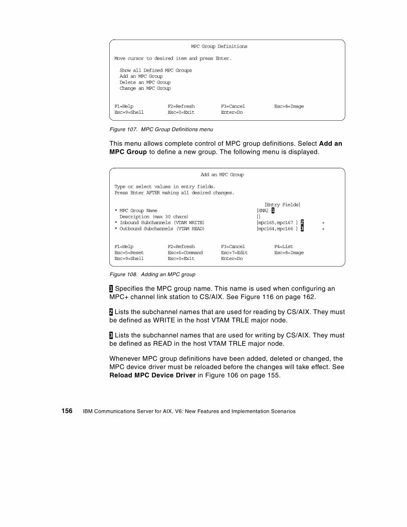
Figure 107. MPC Group Definitions menu
This menu allows complete control of MPC group definitions. Select Add anMPC Group to define a new group. The following menu is displayed.
Figure 108. Adding an MPC group
1 Specifies the MPC group name. This name is used when configuring anMPC+ channel link station to CS/AIX. See Figure 116 on page 162.
2 Lists the subchannel names that are used for reading by CS/AIX. They mustbe defined as WRITE in the host VTAM TRLE major node.
3 Lists the subchannel names that are used for writing by CS/AIX. They mustbe defined as READ in the host VTAM TRLE major node.
Whenever MPC group definitions have been added, deleted or changed, theMPC device driver must be reloaded before the changes will take effect. SeeReload MPC Device Driver in Figure 106 on page 155.
MPC Group Definitions
Move cursor to desired item and press Enter.
Show all Defined MPC GroupsAdd an MPC GroupDelete an MPC GroupChange an MPC Group
F1=Help F2=Refresh F3=Cancel Esc+8=ImageEsc+9=Shell Esc+0=Exit Enter=Do
Add an MPC Group
Type or select values in entry fields.Press Enter AFTER making all desired changes.
[Entry Fields]* MPC Group Name [SNA] 1Description (max 30 chars) []
* Inbound Subchannels (VTAM WRITE) [mpc165,mpc167 ] 2 +* Outbound Subchannels (VTAM READ) [mpc164,mpc166 ] 3 +
F1=Help F2=Refresh F3=Cancel F4=ListEsc+5=Reset Esc+6=Command Esc+7=Edit Esc+8=ImageEsc+9=Shell Esc+0=Exit Enter=Do
156 IBM Communications Server for AIX, V6: New Features and Implementation Scenarios

After the MPC Group has been added, selecting Show all Defined MPCGroups (see Figure 107 on page 156) results in the following display.
Figure 109. Show defined MPC groups output
8.4.5.4 Make and configure the ESCON PCI adapterWhen an ESCON channel adapter is initially installed and configured, it iscontrolled by the standard ARTIC-based device driver. The Make andConfigure All ESCON PCI Adapters process will unconfigure the ARTICdevice driver and reconfigure the ESCON device driver.
From the ESCON Channel PCI Adapter menu shown in Figure 98 on page150, select Manage ESCON Channel PCI Adapters. The following menu isdisplayed.
Figure 110. Managing ESCON channel PCI adapters
From this menu, select Make and Configure All ESCON Adapters. This willreconfigure the adapter for ESCON support.
COMMAND STATUS
Command: OK stdout: yes stderr: no
Before command completion, additional instructions may appear below.
Group Name Inbound Subchannels Outbound Subchannels--------------------------------------------------------------SNA mpc165 mpc164
mpc167 mpc166
F1=Help F2=Refresh F3=Cancel Esc+6=CommandEsc+8=Image Esc+9=Shell Esc+0=Exit /=Findn=Find Next
Manage ESCON Channel PCI Adapters
Move cursor to desired item and press Enter.
Show all ESCON Channel AdaptersMake and Configure all ESCON PCI AdaptersTake an ESCON Channel Adapter offlinePut an ESCON Channel Adapter Online
F1=Help F2=Refresh F3=Cancel F8=ImageF9=Shell F10=Exit Enter=Do
Chapter 8. MPC+ support 157
8.4.6 Configure the adapter to CS/AIXSee item 6 in Figure 91 on page 144 to check where we are in the MPC+configuration process.
For CS/AIX to use the ESCON PCI channel, three definitions must be addedto the CS/AIX configuration:
1. DLC
2. Port
3. Link station
The SMIT interface, the Motif interface, the snaadmin command line, or theWeb Administration interface may be used to create these definitions. Whenusing the Motif interface, the DLC is defined automatically when the port isdefined. We will use the Motif interface for this scenario.
8.4.6.1 Add a port definition to CS/AIXUsing xsnaadmin, click Services -> Connectivity -> New Port.
158 IBM Communications Server for AIX, V6: New Features and Implementation Scenarios
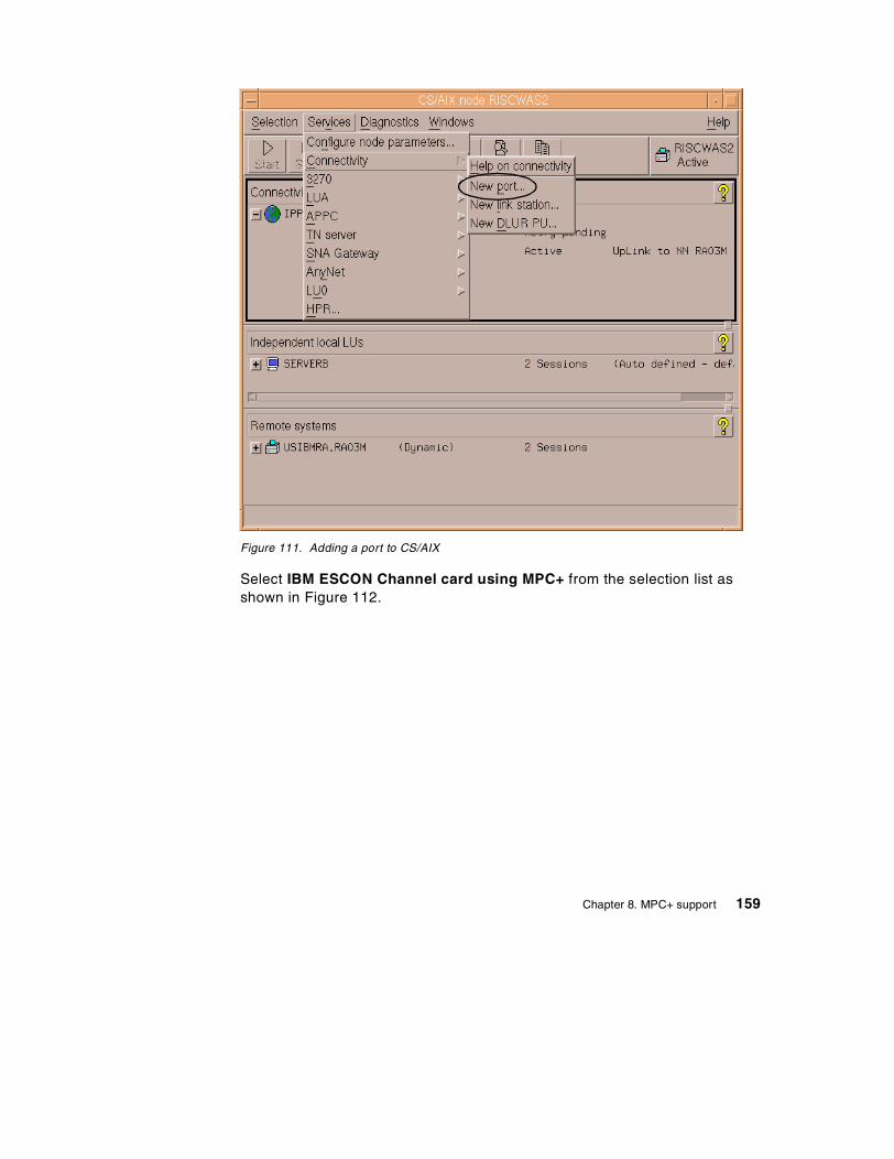
Figure 111. Adding a port to CS/AIX
Select IBM ESCON Channel card using MPC+ from the selection list asshown in Figure 112.
Chapter 8. MPC+ support 159
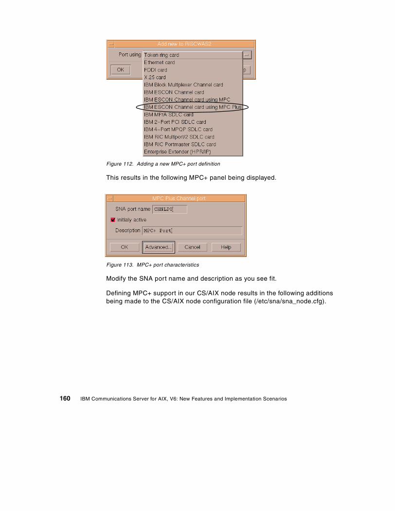
Figure 112. Adding a new MPC+ port definition
This results in the following MPC+ panel being displayed.
Figure 113. MPC+ port characteristics
Modify the SNA port name and description as you see fit.
Defining MPC+ support in our CS/AIX node results in the following additionsbeing made to the CS/AIX node configuration file (/etc/sna/sna_node.cfg).
160 IBM Communications Server for AIX, V6: New Features and Implementation Scenarios
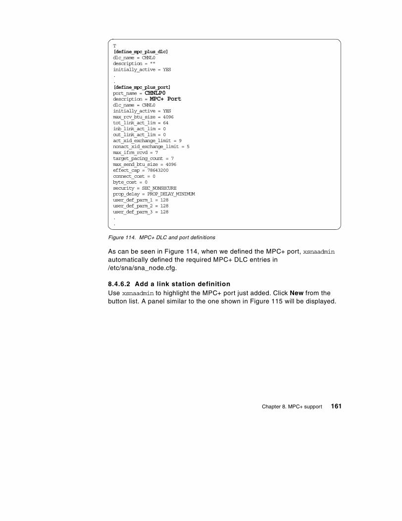
Figure 114. MPC+ DLC and port definitions
As can be seen in Figure 114, when we defined the MPC+ port, xsnaadminautomatically defined the required MPC+ DLC entries in/etc/sna/sna_node.cfg.
8.4.6.2 Add a link station definitionUse xsnaadmin to highlight the MPC+ port just added. Click New from thebutton list. A panel similar to the one shown in Figure 115 will be displayed.
T[define_mpc_plus_dlc]dlc_name = CHNL0description = ""initially_active = YES..[define_mpc_plus_port]port_name = CHNLP0description = MPC+ Portdlc_name = CHNL0initially_active = YESmax_rcv_btu_size = 4096tot_link_act_lim = 64inb_link_act_lim = 0out_link_act_lim = 0act_xid_exchange_limit = 9nonact_xid_exchange_limit = 5max_ifrm_rcvd = 7target_pacing_count = 7max_send_btu_size = 4096effect_cap = 78643200connect_cost = 0byte_cost = 0security = SEC_NONSECUREprop_delay = PROP_DELAY_MINIMUMuser_def_parm_1 = 128user_def_parm_2 = 128user_def_parm_3 = 128..
Chapter 8. MPC+ support 161
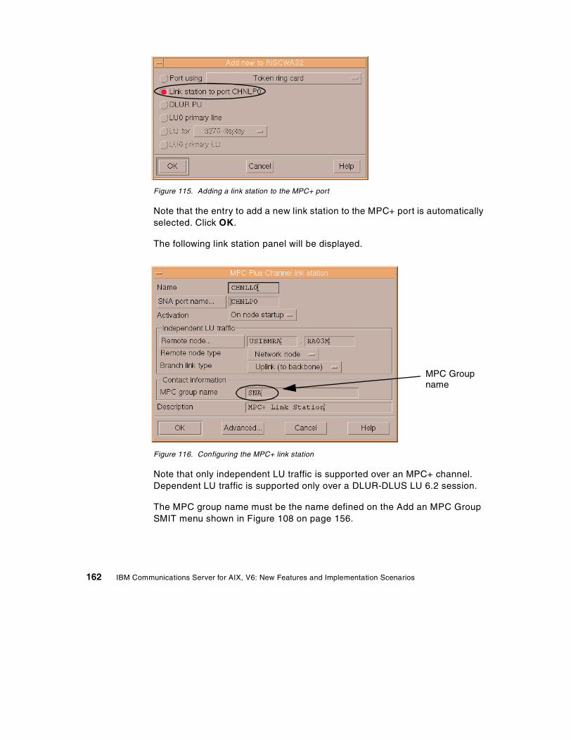
Figure 115. Adding a link station to the MPC+ port
Note that the entry to add a new link station to the MPC+ port is automaticallyselected. Click OK.
The following link station panel will be displayed.
Figure 116. Configuring the MPC+ link station
Note that only independent LU traffic is supported over an MPC+ channel.Dependent LU traffic is supported only over a DLUR-DLUS LU 6.2 session.
The MPC group name must be the name defined on the Add an MPC GroupSMIT menu shown in Figure 108 on page 156.
MPC Groupname
162 IBM Communications Server for AIX, V6: New Features and Implementation Scenarios
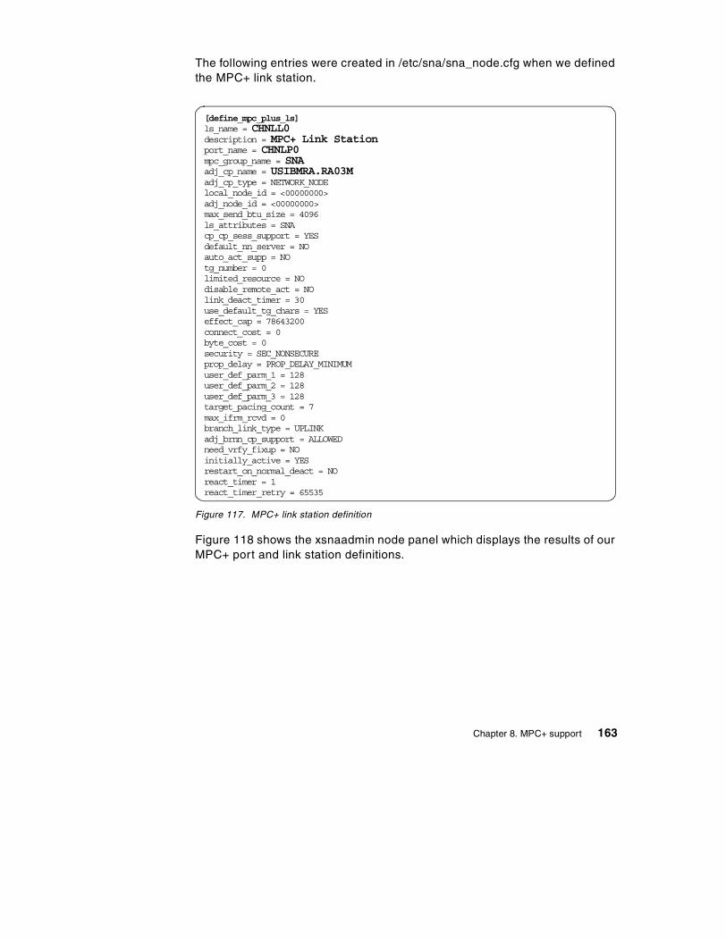
The following entries were created in /etc/sna/sna_node.cfg when we definedthe MPC+ link station.
Figure 117. MPC+ link station definition
Figure 118 shows the xsnaadmin node panel which displays the results of ourMPC+ port and link station definitions.
[define_mpc_plus_ls]ls_name = CHNLL0description = MPC+ Link Stationport_name = CHNLP0mpc_group_name = SNAadj_cp_name = USIBMRA.RA03Madj_cp_type = NETWORK_NODElocal_node_id = <00000000>adj_node_id = <00000000>max_send_btu_size = 4096ls_attributes = SNAcp_cp_sess_support = YESdefault_nn_server = NOauto_act_supp = NOtg_number = 0limited_resource = NOdisable_remote_act = NOlink_deact_timer = 30use_default_tg_chars = YESeffect_cap = 78643200connect_cost = 0byte_cost = 0security = SEC_NONSECUREprop_delay = PROP_DELAY_MINIMUMuser_def_parm_1 = 128user_def_parm_2 = 128user_def_parm_3 = 128target_pacing_count = 7max_ifrm_rcvd = 0branch_link_type = UPLINKadj_brnn_cp_support = ALLOWEDneed_vrfy_fixup = NOinitially_active = YESrestart_on_normal_deact = NOreact_timer = 1react_timer_retry = 65535
Chapter 8. MPC+ support 163
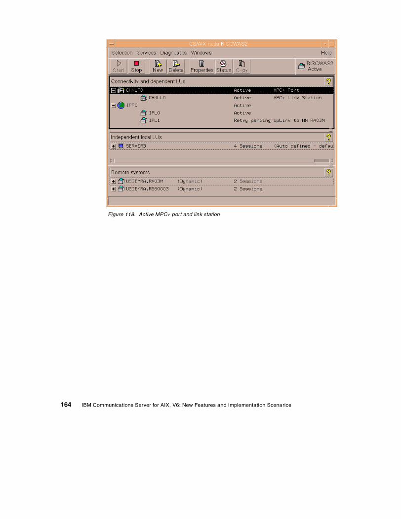
Figure 118. Active MPC+ port and link station
164 IBM Communications Server for AIX, V6: New Features and Implementation Scenarios
Chapter 9. DDDLU enhancement
DDDLU is an acronym for Dynamic Definition of Dependent LUs. It issometimes referred to as Self-Defining Dependent LUs (SDDLU). Thisfeature allows dependent LU definitions to be dynamically created on the hostby VTAM when they are needed.
If the host VTAM is DDDLU capable, it will send information to CS/AIX whenthe link station activates to indicate that the host supports DDDLU. When ahost LU is needed, CS/AIX sends in a Reply Product Set ID (PSID) NetworkManagement Vector Transport (NMVT) with the required information VTAMneeds to dynamically define the dependent LU.
Dependent LU definitions must still be defined on the CS/AIX node. There areno configuration changes in CS/AIX when connecting to DDDLU capablehosts.
Support for DDDLU hosts was first introduced in CS/AIX V5.
IBM Communications Server for AIX, Version 6 introduces DDDLU power-offsupport.
9.1 DDDLU power-off feature
The new DDDLU power-off feature allows CS/AIX V6 to send an NMVTpower-off message to the host when an LU or application ends. This allowsthe host (or an application at the host end) to delete the dynamically createdLU from its tables.
This feature affects LU types 0-3 only. The NMVT power-off message is sentwhen an application terminates its use of an LU if the following are true:
• The host supports DDDLU.
• CS/AIX V6 is configured to send the NMVT power-off message.
Using DDDLU without the power-off feature requires no special definitions onthe CS/AIX side. The link station and all dependent LUs still must be defined.
However, sending the NMVT power-off message requires configurationchanges. Sending the NMVT power-off message is configurable on a per-PUbasis. The default is to not send the NMVT power-off message.
The NMVT power-off message support must be configured using thesnaadmin command line interface or a node operator facility (NOF) API
© Copyright IBM Corp. 2000 165
program. The other CS/AIX configuration tools (SMIT, Motif administrationprogram, Web administration program) do not expose the power-off option.
The following snaadmin commands support specification of the DDDLUpower-off parameter:
define_internal_pu defines a PU on the local node that is served by DLUR
define_channel_ls defines or modifies a channel link station
define_mpc_ls defines or modifies an MPC link station
define_qllc_ls defines or modifies an QLLC link station
define_sdlc_ls defines or modifies an SDLC link station.
define_tr_ls defines or modifies a token-ring link station.
define_ethernet_ls defines or modifies an Ethernet link station.
define_fddi_ls defines or modifies an FDDI link station.
The parameter on each of these commands that controls the DDDLUpower-off support is:
dddlu_offline_supported = NO,YES (NO)
This parameter specifies whether the local PU should send NMVT power-offmessages to the host. If the host system supports DDDLU, CS/AIX sendsNMVT power-off to the host when it has finished using a dynamically definedLU. The default is NO.
To modify the value for the dddlu_offline_supported parameter withoutresetting other parameter values, issue snaadmin -c define_* and specifythe resource name to be changed. For example:
snaadmin -c define_tr_ls, ls_name=TRL0, dddlu_offline_supported=YES
IBM Communications Server for AIX Administration Command Reference,Version 6, SC31-8587, documents the use of these commands andparameters. However, the Administration Command Reference publicationshipped with CS/AIX describes the incorrect DDDLU power-off parameter.It states that the DDDLU power-off parameter is:
pu_can_send_dddlu_offline
This is incorrect. The correct parameter is:
dddlu_offline_supported
DDDLU Documentation
166 IBM Communications Server for AIX, V6: New Features and Implementation Scenarios

Part 4. Administration
© Copyright IBM Corp. 2000 167

168 IBM Communications Server for AIX, V6: New Features and Implementation Scenarios
Chapter 10. Web Administration program
In this chapter, we will review the range of tools provided with CS/AIX thatmay be used to configure and administer the system. We will then go intomore detail on using the new Web Administration program to configure andmanage a CS/AIX system.
10.1 Overview
CS/AIX includes the following administration tools:
• Motif administration program
• SMIT
• Command-line administration program
• Web Administration program
• Service point command facility
• Node Operator Facility (NOF) API
10.1.1 Motif administration programThe easiest way to define and modify the CS/AIX configuration is to use theMotif administration program (xsnaadmin). All the CS/AIX panels you haveseen up to now in this book are from the Motif administration program. Thisprogram provides a graphical user interface from which you can view andmanage CS/AIX resources.
The Motif administration program can be used to manage both noderesources and domain resources. For each type of communications (such as3270 or APPC), the program guides you in setting up the configuration of therequired resources.
The Motif administration program includes help panels that provide overviewinformation for SNA and CS/AIX, reference information for CS/AIX dialog, andguidance for performing specific tasks.
Before starting the Motif administration program, make sure the CS/AIXsoftware is enabled on the local node. The Motif administration program willnot automatically start CS/AIX. Enable the CS/AIX software by issuing thecommand:
sna start
© Copyright IBM Corp. 2000 169
To start the Motif Administration program in the background, issue thefollowing command:
xsnaadmin &
The Motif administration program initially presents the Node window, whichdisplays resource information for the local node. If you have not yetconfigured the node, the program prompts you to do so and leads youthrough the steps required to configure it.
Note: The Motif administration program enables you to set up all requiredparameters for standard CS/AIX configurations. For advancedparameters, the Motif administration program supplies default values.You need to supply only the essential configuration information, whichenables you to set up SNA communications quickly and easily.
The main advantage to using the Motif administration program to manageyour system is that it provides context-sensitive guidance for nodeconfiguration and management. The panels and data entry fields displayedare dynamically presented and modified based on data entered and fieldselections made on the current and previous panels.
10.1.2 SMIT administration programSMIT provides a menu-based interface to configure and manage CS/AIXresources. It can be used either from a Motif interface or from an ASCIIterminal.
SMIT provides the same administration functions as the Motif administrationprogram, including help panels for each SMIT panel. Before you can useSMIT to administer CS/AIX, the CS/AIX software must be enabled on thelocal node. If you attempt to use SMIT to configure a CS/AIX system withoutfirst enabling the software, it is enabled for you.
Note that unlike the Motif administration program, the SMIT dialogs are notdynamic and context-sensitive.
10.1.3 Command-line administration programThe command-line administration program, snaadmin, enables you to issuecommands to configure and manage individual CS/AIX resources. You canuse snaadmin either directly from the AIX command prompt or from within ashell script.
Commands can be issued to the CS/AIX node to manage the node’sresources, or to the domain configuration file to manage domain resources.
170 IBM Communications Server for AIX, V6: New Features and Implementation Scenarios
The snaadmin command-line administration program can be used for allpossible CS/AIX configuration parameters, while xsnaadmin, SMIT, and theWeb Administration program only expose the most common subset ofparameters.
You can get help for command-line administration by using any of thefollowing commands:
snaadmin -h provides basic help for command-lineadministration and usage information forcommand-line help.
snaadmin -h -d provides a list of commands that can be suppliedto the snaadmin program.
snaadmin -h command provides help for the named command.
snaadmin -h -d command provides detailed help for the named command,including a list of the configuration parametersthat can be specified with the command.
Refer to the Communications Server for AIX Administration CommandReference, SC31-8587, for more information.
10.1.4 Network operator facility APIThe CS/AIX NOF application program interface allows you to write your ownapplication programs to administer CS/AIX.
All the CS/AIX administration tools use the NOF API.
The CS/AIX NOF API provides access to a standard set of commands, calledNOF verbs, that can be used to administer the CS/AIX system from within anapplication program. These verbs enable you to define and delete resources,specify CS/AIX parameters such as diagnostics levels and file names, startand stop defined resources, and query the definition or current status ofresources.
The NOF verbs provide the same functions as commands issued to thecommand-line administration program snaadmin, or as records in a CS/AIXconfiguration file. For example, the NOF verb DEFINE_LOCAL_LU isequivalent both to a define_local_lu command issued to the snaadminprogram, and to a define_local_lu record in a configuration file; all three ofthem perform the same function, which is to specify the parameters of aCS/AIX local APPC LU.
Chapter 10. Web Administration program 171
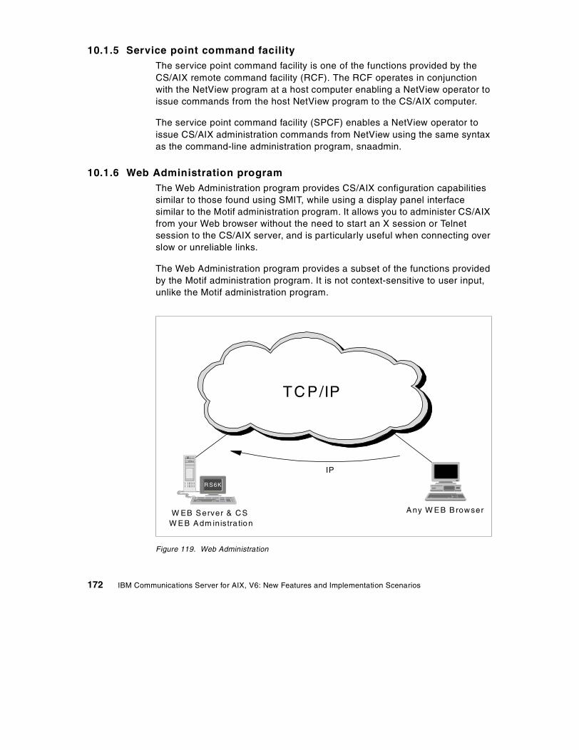
10.1.5 Service point command facilityThe service point command facility is one of the functions provided by theCS/AIX remote command facility (RCF). The RCF operates in conjunctionwith the NetView program at a host computer enabling a NetView operator toissue commands from the host NetView program to the CS/AIX computer.
The service point command facility (SPCF) enables a NetView operator toissue CS/AIX administration commands from NetView using the same syntaxas the command-line administration program, snaadmin.
10.1.6 Web Administration programThe Web Administration program provides CS/AIX configuration capabilitiessimilar to those found using SMIT, while using a display panel interfacesimilar to the Motif administration program. It allows you to administer CS/AIXfrom your Web browser without the need to start an X session or Telnetsession to the CS/AIX server, and is particularly useful when connecting overslow or unreliable links.
The Web Administration program provides a subset of the functions providedby the Motif administration program. It is not context-sensitive to user input,unlike the Motif administration program.
Figure 119. Web Administration
W EB Server & CSW EB Adm inistra tion
Any W EB Browser
N T
R S6K
IP
TC P/IP
172 IBM Communications Server for AIX, V6: New Features and Implementation Scenarios
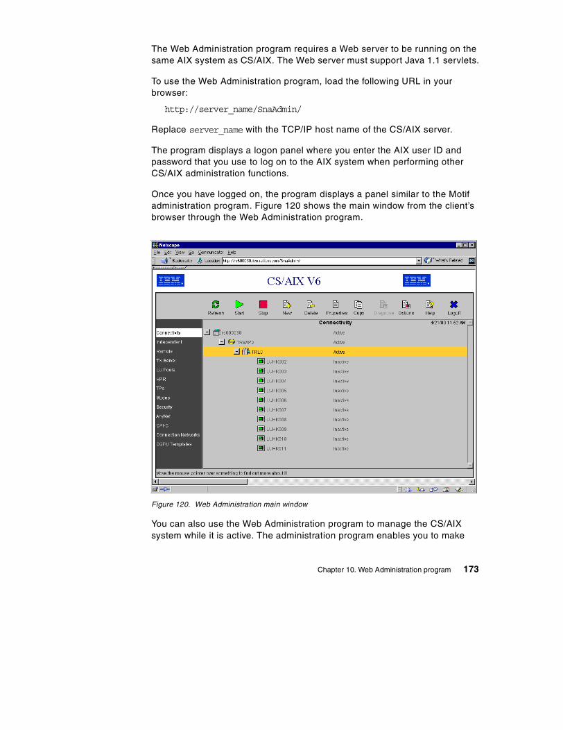
The Web Administration program requires a Web server to be running on thesame AIX system as CS/AIX. The Web server must support Java 1.1 servlets.
To use the Web Administration program, load the following URL in yourbrowser:
http://server_name/SnaAdmin/
Replace server_name with the TCP/IP host name of the CS/AIX server.
The program displays a logon panel where you enter the AIX user ID andpassword that you use to log on to the AIX system when performing otherCS/AIX administration functions.
Once you have logged on, the program displays a panel similar to the Motifadministration program. Figure 120 shows the main window from the client’sbrowser through the Web Administration program.
Figure 120. Web Administration main window
You can also use the Web Administration program to manage the CS/AIXsystem while it is active. The administration program enables you to make
Chapter 10. Web Administration program 173
and apply changes to the configuration while CS/AIX is active. You can add,modify, and remove resources (in most cases, even when the node and itsresources are active), and use the modified configuration immediately forcontinued operation.
The Web Administration program enables you to set up all requiredparameters for standard CS/AIX configurations. For advanced parameters,the program supplies default values. You need to supply only the essentialconfiguration information, which enables you to set up SNA communicationsquickly and easily.
Note that the other CS/AIX administration tools (command-line configurationand NOF application programs) provide access to a wider range ofconfiguration parameters and options than those shown in the WebAdministration program. In most cases, however, you can perform all neededconfiguration from this program because it exposes the key fields needed toconfigure and hides the fields that most users should not need to modify.
The default values supplied by the Web Administration program may differfrom those supplied by command-line configuration because the Webprogram can choose values based on the context of the configuration taskbeing performed. Similarly, the default values supplied by the WebAdministration program may differ from those supplied by the Motifadministration program because the Motif program can choose values basedon other choices you have already made in the same dialog.
10.2 Web Administration program implementation
In this section, we discuss configuring the Web Administration program (WebAdmin) connection to the Web server, and Web Administration programusage.
The Web admin component of CS/AIX is contained in the sna.wa fileset onthe product distribution media. It can be installed when CS/AIX is installed, orat a later time.
10.2.1 Supported Web serversThe following Web servers are supported by CS/AIX Web Administration.
• IBM HTTP Server V1.3.6 for AIX (with WebSphere Application Server2.03)
• Apache Server (with Jserv support)
174 IBM Communications Server for AIX, V6: New Features and Implementation Scenarios
• Netscape Enterprise Server V3.01 and V3.51 for AIX (V3.51 isrecommended)
• Lotus Domino Go Server
10.2.2 Configuring a Web server for Web AdministrationIf one of the following Web servers is installed on the AIX system before theWeb admin program is installed, the required links between the Web serverand the CS/AIX Web admin program will be created during installation.
• IBM HTTP Server
• Netscape Enterprise Server
• Lotus Domino Go Server
If you install one of the listed Web servers after installing the Web adminprogram, you need to set up links between Web admin directories and theWeb server’s directories so that the Web server can find the required files.Use the following command to create these links.
/usr/bin/snawebconfig
To undo Web admin changes to all your Web servers, run the command:
/usr/bin/snawebunconfig
If you are using the Web Administration program with a Web server that is notautomatically configured by the /usr/bin/snawebconfig command, you needto set up links between CS/AIX directories and the Web server’s directoriesso that the Web server can find the required files. Use the ln command tocreate these links.
1. The Web server’s servlets directory must be linked to/usr/lib/sna/WebAdmin/Server.
2. The subdirectory SnaAdmin in the Web server’s public HTML directorymust be linked to /usr/lib/sna/WebAdmin/Client.
10.2.3 Invoking the Web Administration programBefore starting the Web Administration program, ensure the following:
• The CS/AIX software is enabled.
• The Web server software is running on the CS/AIX server.
To use the Web Administration program, load the following URL in yourbrowser:
Chapter 10. Web Administration program 175
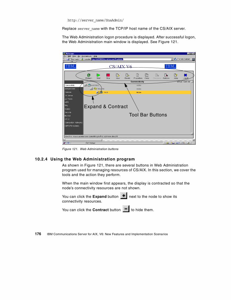
http://server_name/SnaAdmin/
Replace server_name with the TCP/IP host name of the CS/AIX server.
The Web Administration logon procedure is displayed. After successful logon,the Web Administration main window is displayed. See Figure 121.
Figure 121. Web Administration buttons
10.2.4 Using the Web Administration programAs shown in Figure 121, there are several buttons in Web Administrationprogram used for managing resources of CS/AIX. In this section, we cover thetools and the action they perform.
When the main window first appears, the display is contracted so that thenode’s connectivity resources are not shown.
You can click the Expand button next to the node to show itsconnectivity resources.
You can click the Contract button to hide them.
Expand & Contract
Tool Bar Buttons
176 IBM Communications Server for AIX, V6: New Features and Implementation Scenarios
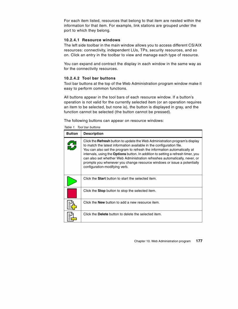
For each item listed, resources that belong to that item are nested within theinformation for that item. For example, link stations are grouped under theport to which they belong.
10.2.4.1 Resource windowsThe left side toolbar in the main window allows you to access different CS/AIXresources: connectivity, independent LUs, TPs, security resources, and soon. Click an entry in the toolbar to view and manage each type of resource.
You can expand and contract the display in each window in the same way asfor the connectivity resources.
10.2.4.2 Tool bar buttonsTool bar buttons at the top of the Web Administration program window make iteasy to perform common functions.
All buttons appear in the tool bars of each resource window. If a button’soperation is not valid for the currently selected item (or an operation requiresan item to be selected, but none is), the button is displayed in gray, and thefunction cannot be selected (the button cannot be pressed).
The following buttons can appear on resource windows:
Table 1. Tool bar buttons
Button Description
Click the Refresh button to update the Web Administration program’s displayto match the latest information available in the configuration file.You can also set the program to refresh the information automatically atintervals, using the Options button. In addition to setting a refresh timer, youcan also set whether Web Administration refreshes automatically, never, orprompts you whenever you change resource windows or issue a potentiallyconfiguration-modifying verb.
Click the Start button to start the selected item.
Click the Stop button to stop the selected item.
Click the New button to add a new resource item.
Click the Delete button to delete the selected item.
Chapter 10. Web Administration program 177
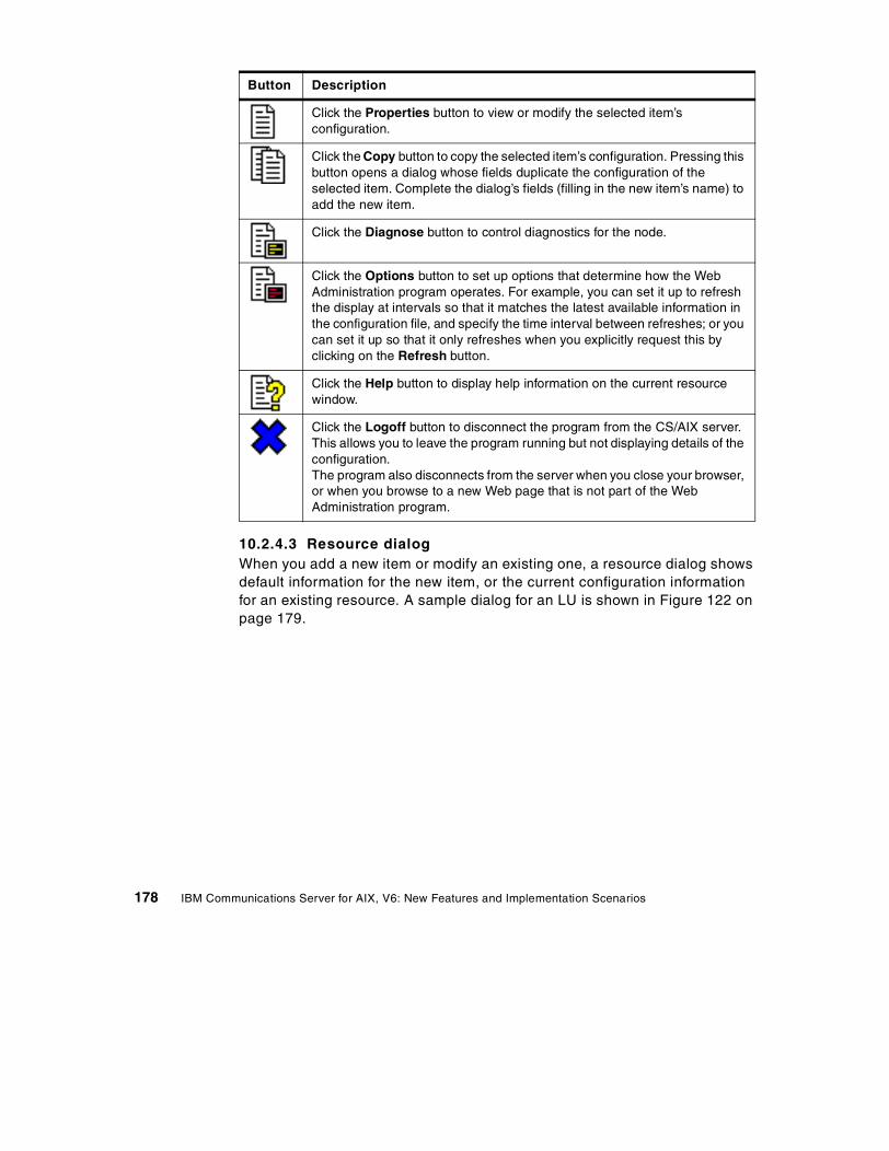
10.2.4.3 Resource dialogWhen you add a new item or modify an existing one, a resource dialog showsdefault information for the new item, or the current configuration informationfor an existing resource. A sample dialog for an LU is shown in Figure 122 onpage 179.
Click the Properties button to view or modify the selected item’sconfiguration.
Click the Copy button to copy the selected item’s configuration. Pressing thisbutton opens a dialog whose fields duplicate the configuration of theselected item. Complete the dialog’s fields (filling in the new item’s name) toadd the new item.
Click the Diagnose button to control diagnostics for the node.
Click the Options button to set up options that determine how the WebAdministration program operates. For example, you can set it up to refreshthe display at intervals so that it matches the latest available information inthe configuration file, and specify the time interval between refreshes; or youcan set it up so that it only refreshes when you explicitly request this byclicking on the Refresh button.
Click the Help button to display help information on the current resourcewindow.
Click the Logoff button to disconnect the program from the CS/AIX server.This allows you to leave the program running but not displaying details of theconfiguration.The program also disconnects from the server when you close your browser,or when you browse to a new Web page that is not part of the WebAdministration program.
Button Description
178 IBM Communications Server for AIX, V6: New Features and Implementation Scenarios
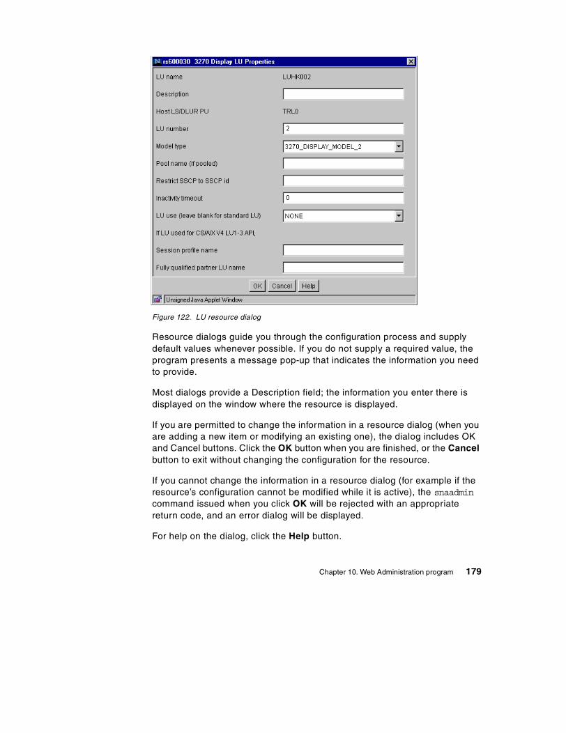
Figure 122. LU resource dialog
Resource dialogs guide you through the configuration process and supplydefault values whenever possible. If you do not supply a required value, theprogram presents a message pop-up that indicates the information you needto provide.
Most dialogs provide a Description field; the information you enter there isdisplayed on the window where the resource is displayed.
If you are permitted to change the information in a resource dialog (when youare adding a new item or modifying an existing one), the dialog includes OKand Cancel buttons. Click the OK button when you are finished, or the Cancelbutton to exit without changing the configuration for the resource.
If you cannot change the information in a resource dialog (for example if theresource’s configuration cannot be modified while it is active), the snaadmincommand issued when you click OK will be rejected with an appropriatereturn code, and an error dialog will be displayed.
For help on the dialog, click the Help button.
Chapter 10. Web Administration program 179
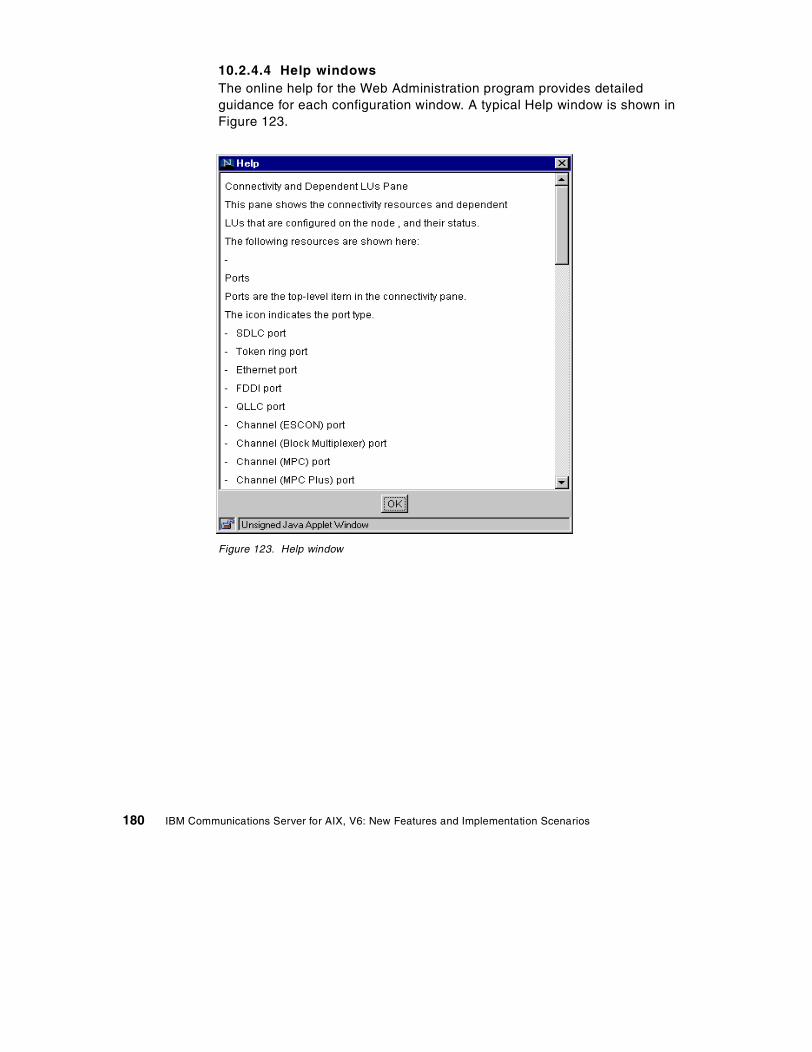
10.2.4.4 Help windowsThe online help for the Web Administration program provides detailedguidance for each configuration window. A typical Help window is shown inFigure 123.
Figure 123. Help window
180 IBM Communications Server for AIX, V6: New Features and Implementation Scenarios
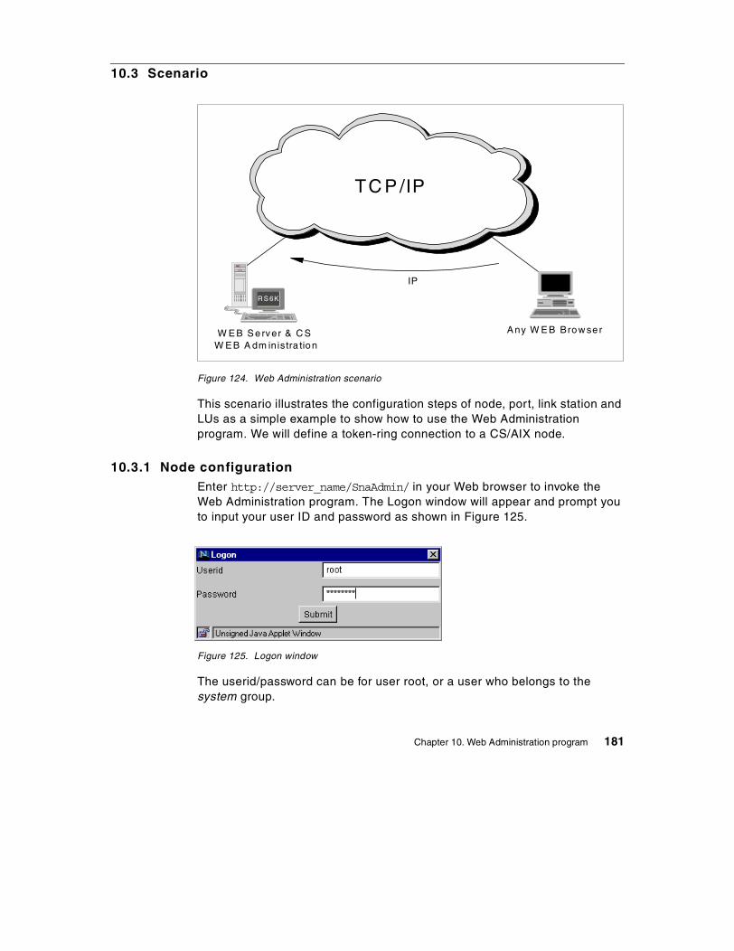
10.3 Scenario
Figure 124. Web Administration scenario
This scenario illustrates the configuration steps of node, port, link station andLUs as a simple example to show how to use the Web Administrationprogram. We will define a token-ring connection to a CS/AIX node.
10.3.1 Node configurationEnter http://server_name/SnaAdmin/ in your Web browser to invoke theWeb Administration program. The Logon window will appear and prompt youto input your user ID and password as shown in Figure 125.
Figure 125. Logon window
The userid/password can be for user root, or a user who belongs to thesystem group.
W E B S erver & C SW E B A dm inistra tion
A ny W E B Brow se r
N TR S 6K
IP
TC P /IP
Chapter 10. Web Administration program 181
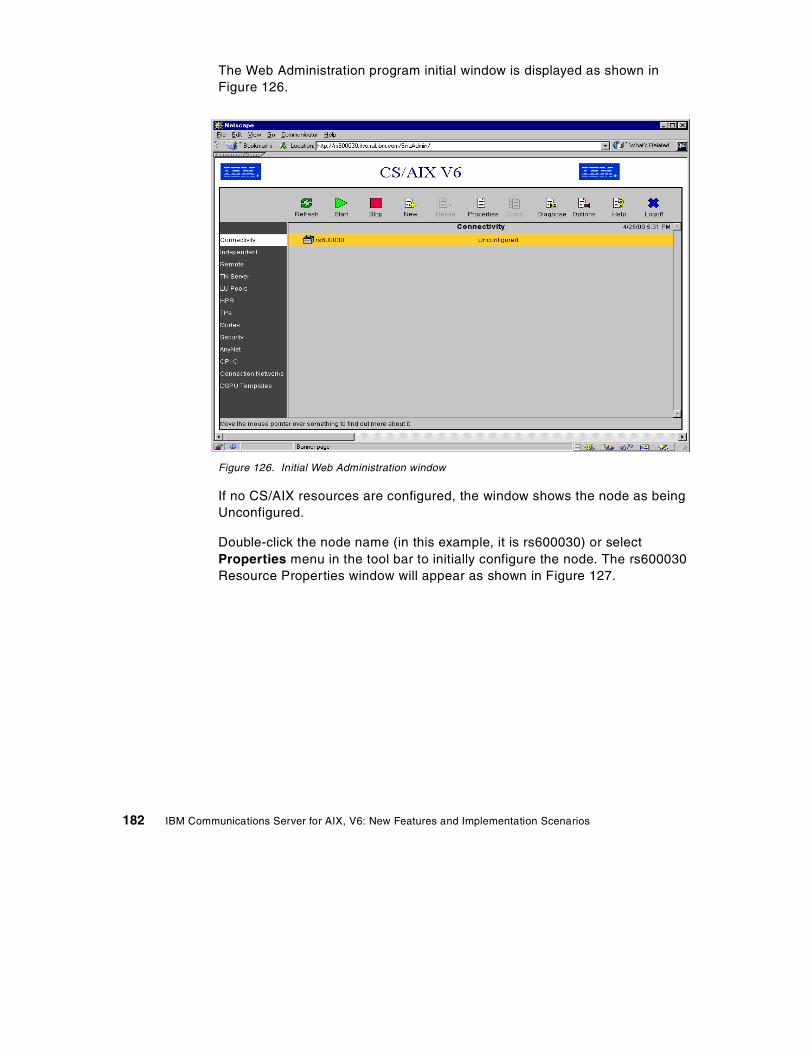
The Web Administration program initial window is displayed as shown inFigure 126.
Figure 126. Initial Web Administration window
If no CS/AIX resources are configured, the window shows the node as beingUnconfigured.
Double-click the node name (in this example, it is rs600030) or selectProperties menu in the tool bar to initially configure the node. The rs600030Resource Properties window will appear as shown in Figure 127.
182 IBM Communications Server for AIX, V6: New Features and Implementation Scenarios
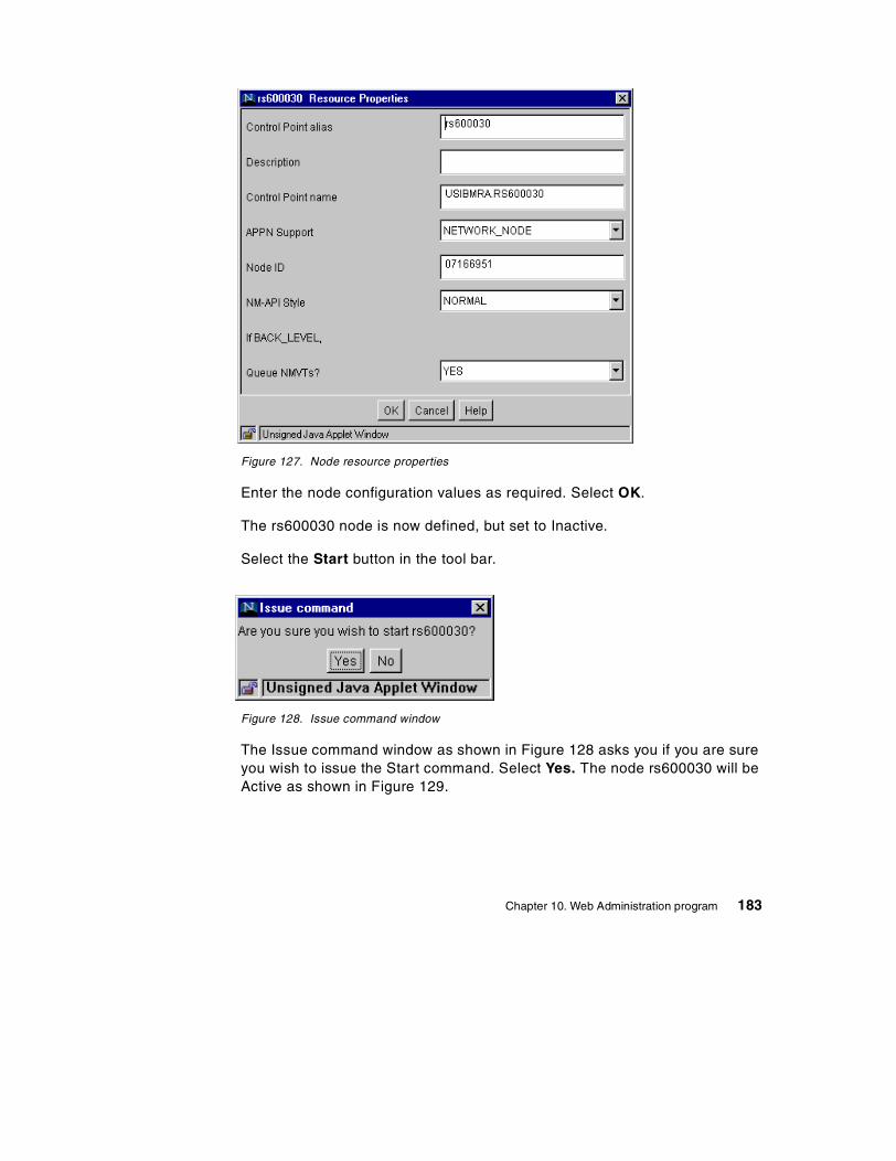
Figure 127. Node resource properties
Enter the node configuration values as required. Select OK.
The rs600030 node is now defined, but set to Inactive.
Select the Start button in the tool bar.
Figure 128. Issue command window
The Issue command window as shown in Figure 128 asks you if you are sureyou wish to issue the Start command. Select Yes. The node rs600030 will beActive as shown in Figure 129.
Chapter 10. Web Administration program 183
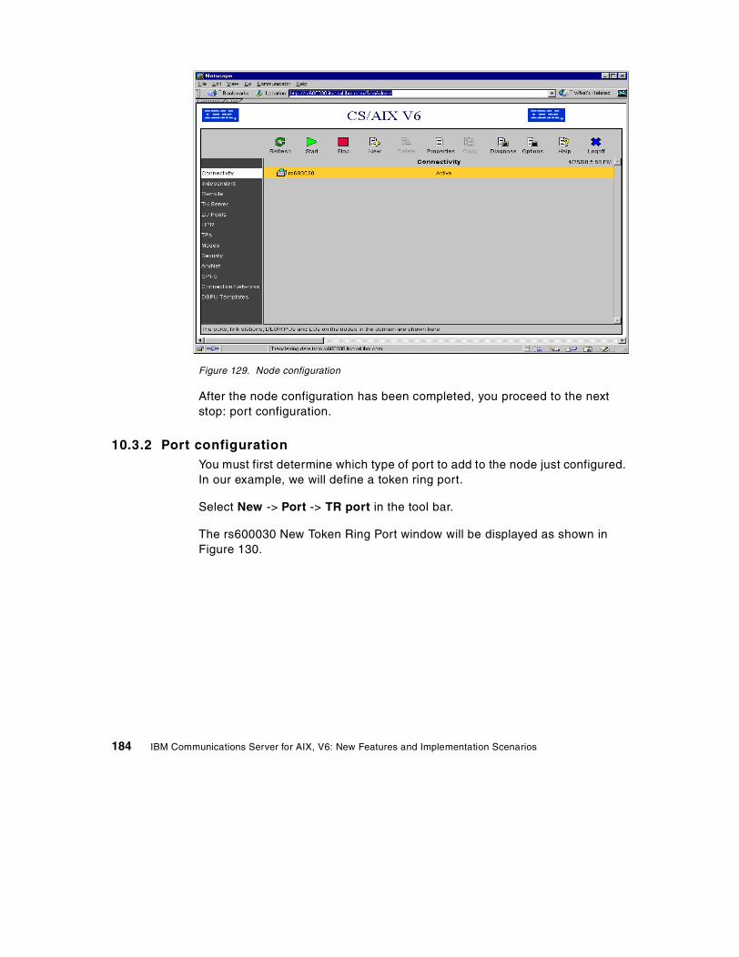
Figure 129. Node configuration
After the node configuration has been completed, you proceed to the nextstop: port configuration.
10.3.2 Port configurationYou must first determine which type of port to add to the node just configured.In our example, we will define a token ring port.
Select New -> Port -> TR port in the tool bar.
The rs600030 New Token Ring Port window will be displayed as shown inFigure 130.
184 IBM Communications Server for AIX, V6: New Features and Implementation Scenarios
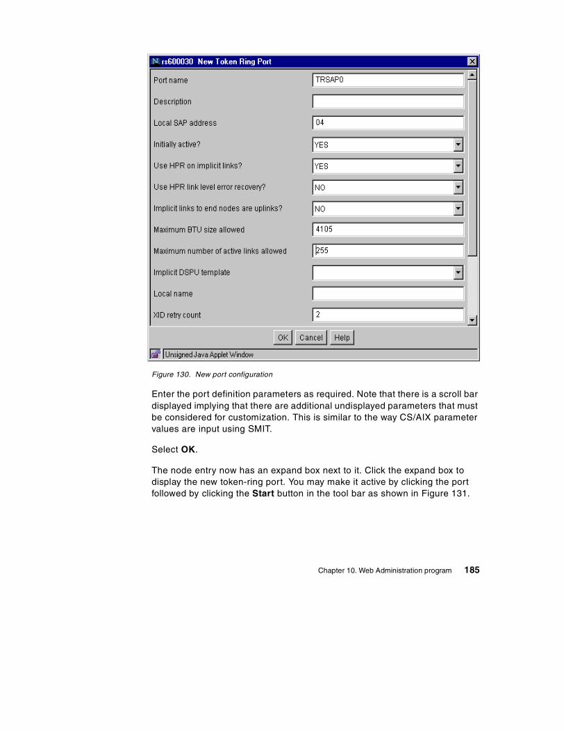
Figure 130. New port configuration
Enter the port definition parameters as required. Note that there is a scroll bardisplayed implying that there are additional undisplayed parameters that mustbe considered for customization. This is similar to the way CS/AIX parametervalues are input using SMIT.
Select OK.
The node entry now has an expand box next to it. Click the expand box todisplay the new token-ring port. You may make it active by clicking the portfollowed by clicking the Start button in the tool bar as shown in Figure 131.
Chapter 10. Web Administration program 185
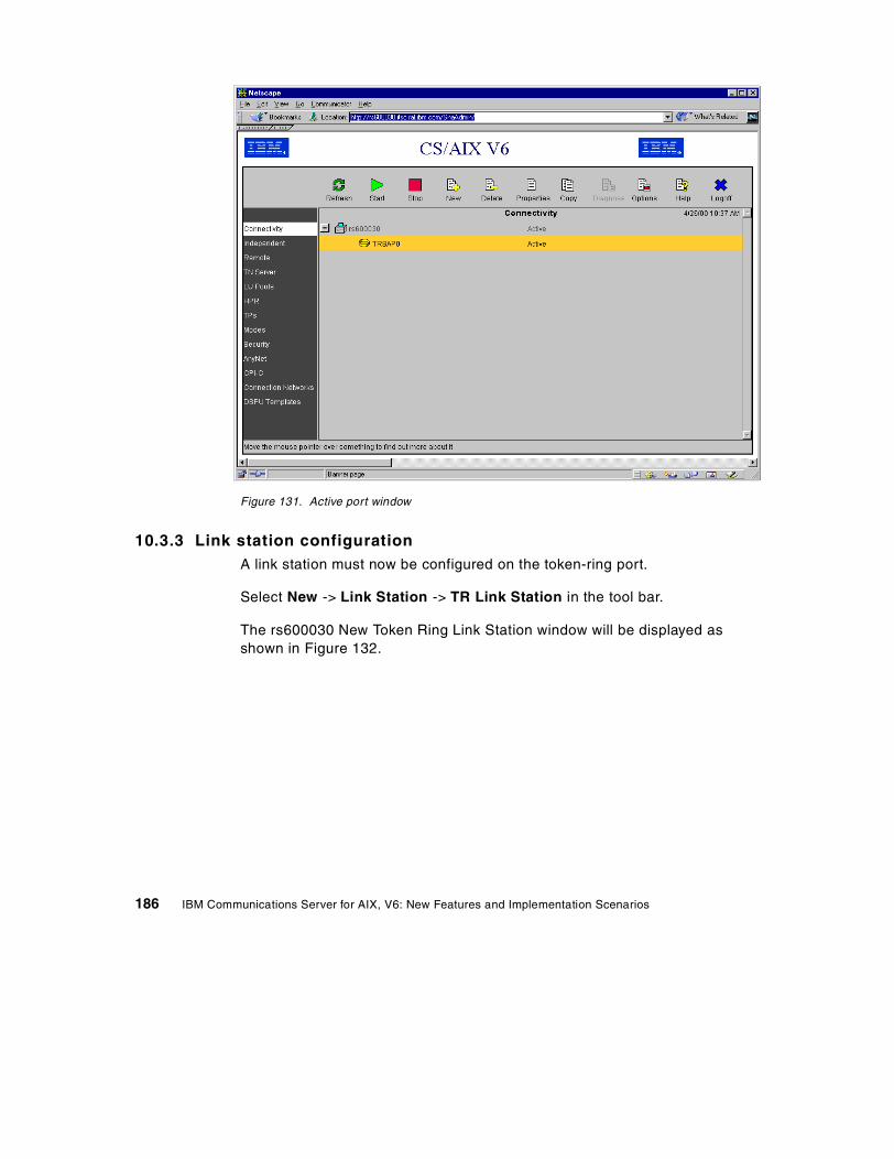
Figure 131. Active port window
10.3.3 Link station configurationA link station must now be configured on the token-ring port.
Select New -> Link Station -> TR Link Station in the tool bar.
The rs600030 New Token Ring Link Station window will be displayed asshown in Figure 132.
186 IBM Communications Server for AIX, V6: New Features and Implementation Scenarios
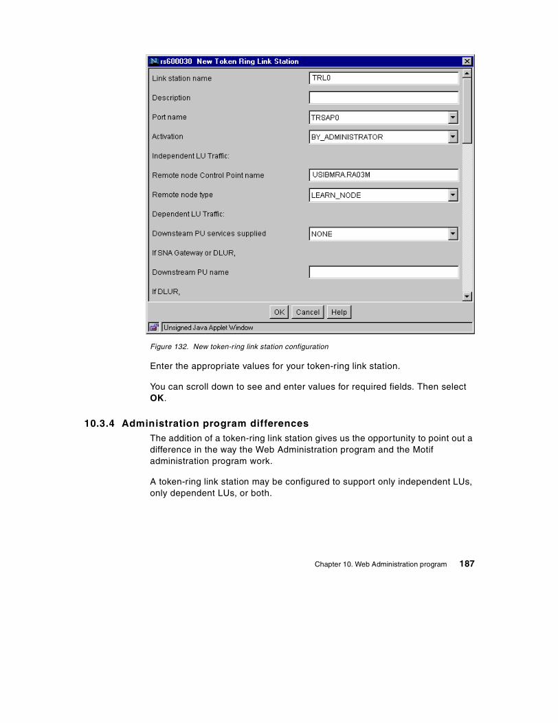
Figure 132. New token-ring link station configuration
Enter the appropriate values for your token-ring link station.
You can scroll down to see and enter values for required fields. Then selectOK.
10.3.4 Administration program differencesThe addition of a token-ring link station gives us the opportunity to point out adifference in the way the Web Administration program and the Motifadministration program work.
A token-ring link station may be configured to support only independent LUs,only dependent LUs, or both.
Chapter 10. Web Administration program 187
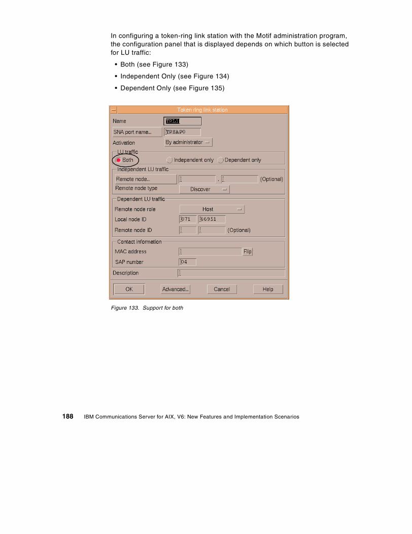
In configuring a token-ring link station with the Motif administration program,the configuration panel that is displayed depends on which button is selectedfor LU traffic:
• Both (see Figure 133)
• Independent Only (see Figure 134)
• Dependent Only (see Figure 135)
Figure 133. Support for both
188 IBM Communications Server for AIX, V6: New Features and Implementation Scenarios
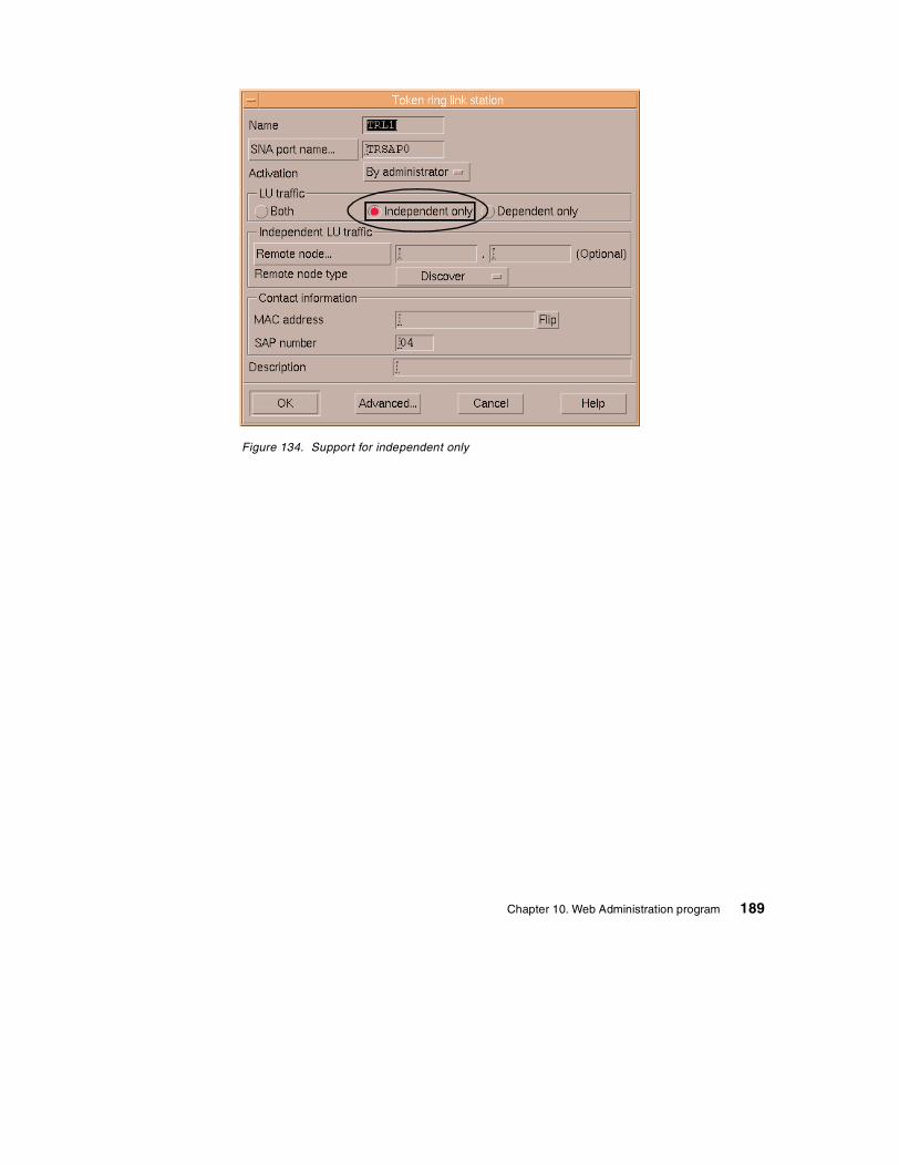
Figure 134. Support for independent only
Chapter 10. Web Administration program 189
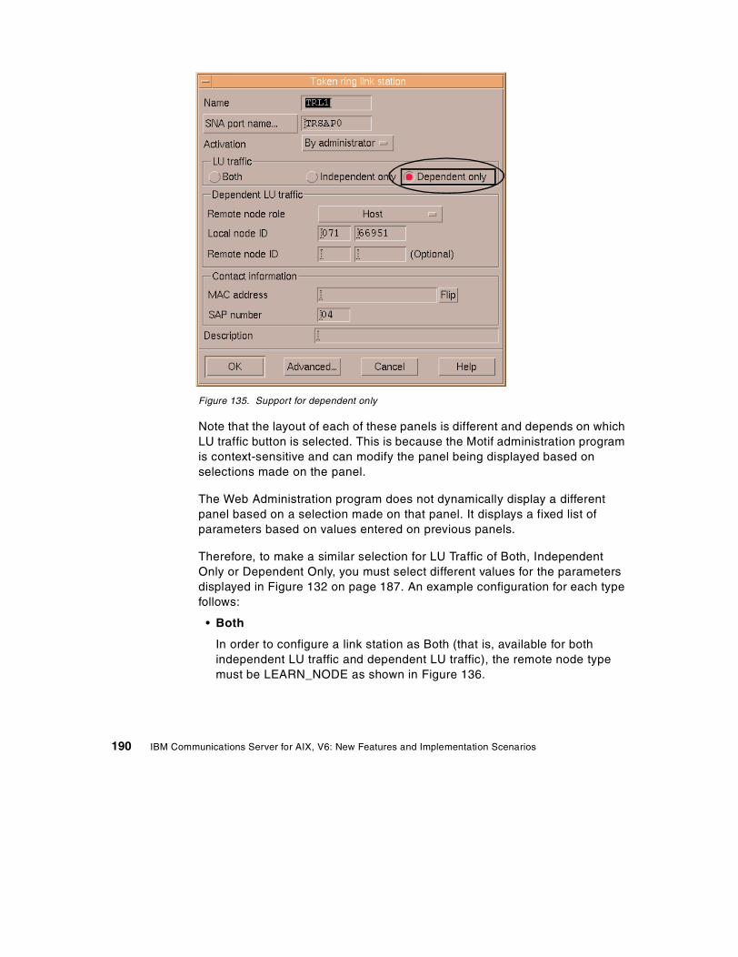
Figure 135. Support for dependent only
Note that the layout of each of these panels is different and depends on whichLU traffic button is selected. This is because the Motif administration programis context-sensitive and can modify the panel being displayed based onselections made on the panel.
The Web Administration program does not dynamically display a differentpanel based on a selection made on that panel. It displays a fixed list ofparameters based on values entered on previous panels.
Therefore, to make a similar selection for LU Traffic of Both, IndependentOnly or Dependent Only, you must select different values for the parametersdisplayed in Figure 132 on page 187. An example configuration for each typefollows:
• Both
In order to configure a link station as Both (that is, available for bothindependent LU traffic and dependent LU traffic), the remote node typemust be LEARN_NODE as shown in Figure 136.
190 IBM Communications Server for AIX, V6: New Features and Implementation Scenarios
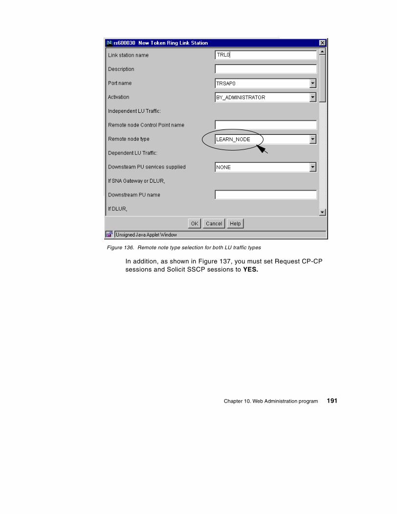
Figure 136. Remote note type selection for both LU traffic types
In addition, as shown in Figure 137, you must set Request CP-CPsessions and Solicit SSCP sessions to YES.
Chapter 10. Web Administration program 191
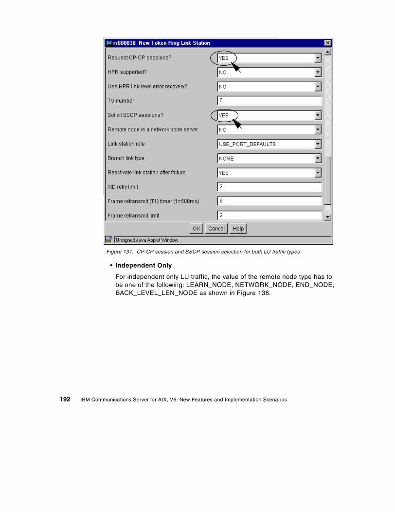
Figure 137. CP-CP session and SSCP session selection for both LU traffic types
• Independent Only
For independent only LU traffic, the value of the remote node type has tobe one of the following: LEARN_NODE, NETWORK_NODE, END_NODE,BACK_LEVEL_LEN_NODE as shown in Figure 138.
192 IBM Communications Server for AIX, V6: New Features and Implementation Scenarios
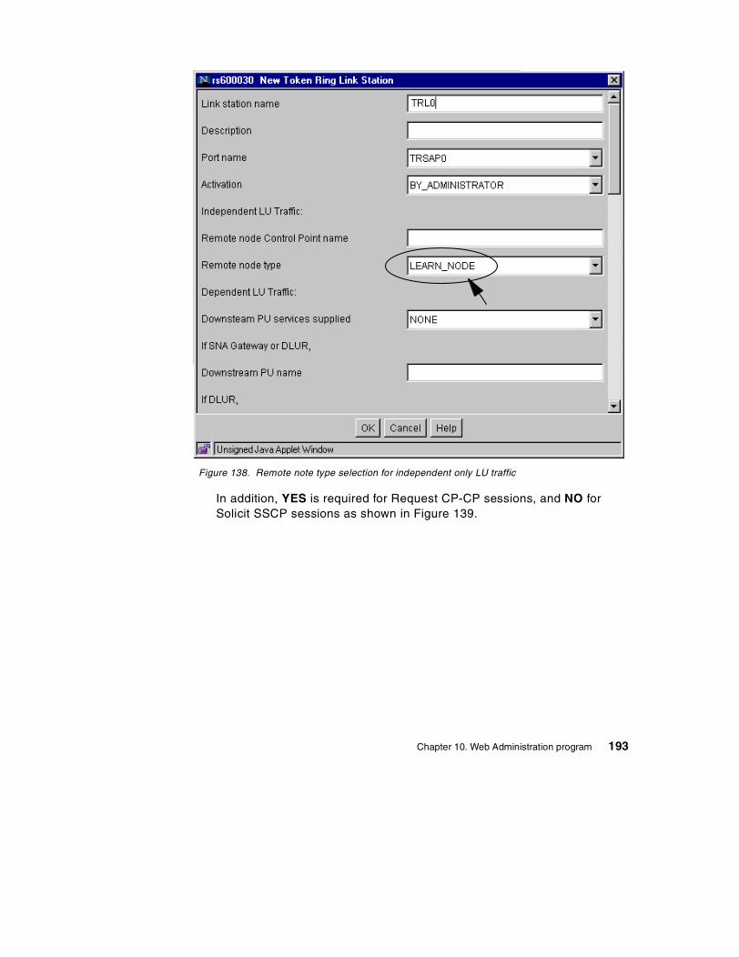
Figure 138. Remote note type selection for independent only LU traffic
In addition, YES is required for Request CP-CP sessions, and NO forSolicit SSCP sessions as shown in Figure 139.
Chapter 10. Web Administration program 193
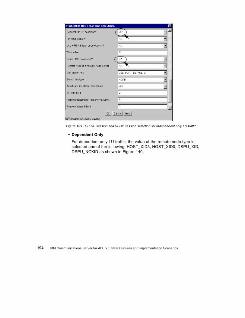
Figure 139. CP-CP session and SSCP session selection for Independent only LU traffic
• Dependent Only
For dependent only LU traffic, the value of the remote node type isselected one of the following: HOST_XID3, HOST_XID0, DSPU_XID,DSPU_NOXID as shown in Figure 140.
194 IBM Communications Server for AIX, V6: New Features and Implementation Scenarios
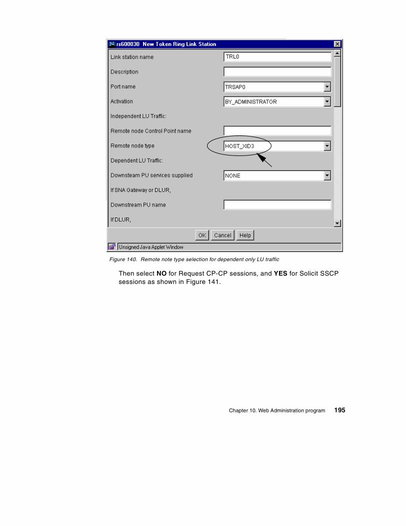
Figure 140. Remote note type selection for dependent only LU traffic
Then select NO for Request CP-CP sessions, and YES for Solicit SSCPsessions as shown in Figure 141.
Chapter 10. Web Administration program 195
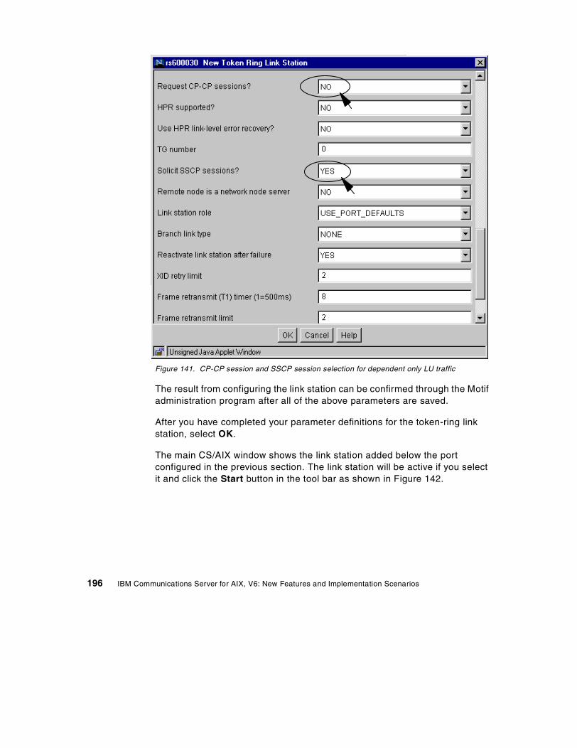
Figure 141. CP-CP session and SSCP session selection for dependent only LU traffic
The result from configuring the link station can be confirmed through the Motifadministration program after all of the above parameters are saved.
After you have completed your parameter definitions for the token-ring linkstation, select OK.
The main CS/AIX window shows the link station added below the portconfigured in the previous section. The link station will be active if you selectit and click the Start button in the tool bar as shown in Figure 142.
196 IBM Communications Server for AIX, V6: New Features and Implementation Scenarios

Figure 142. Active link station window
10.3.5 LUs configurationDepending on your configuration requirements, you may now add LUs to thelink station you just configured. In this section, we will add new a 3270Display LU.
Select New -> LU -> 3270 Display LU in the tool bar.
The rs600030 New 3270 Display LU window is displayed as shown in Figure143.
Chapter 10. Web Administration program 197
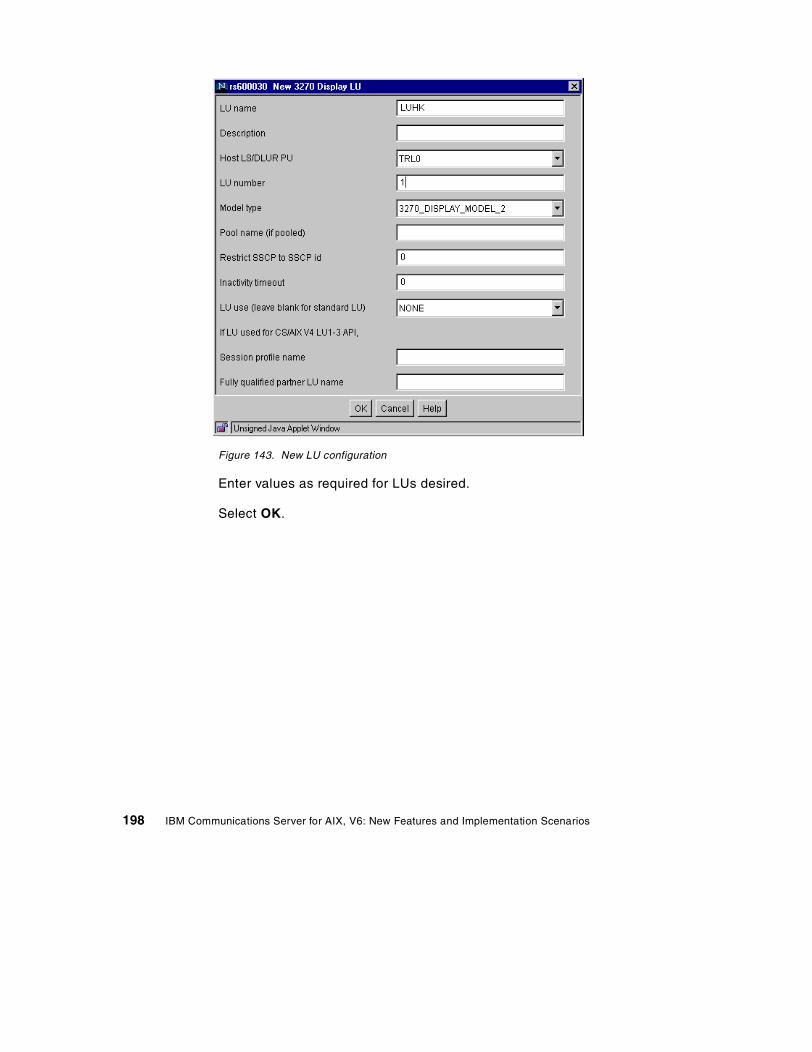
Figure 143. New LU configuration
Enter values as required for LUs desired.
Select OK.
198 IBM Communications Server for AIX, V6: New Features and Implementation Scenarios
Chapter 11. CS/AIX licensing
Communications Server for AIX, Version 6 monitors access to users andpartner nodes. CS/AIX licensing is based on the number of active concurrentusers and links to partner nodes. Current and peak usage is recorded to helpdetermine whether your usage is within the limits permitted by your license.
This chapter covers the CS/AIX licensing and monitoring facilities.
11.1 Overview
IBM Communications Server for AIX, Version 6 includes many functions andfeatures to meet the varying networking connectivity requirements for a broadset of implementation scenarios. In many cases, however, customers maychoose to implement only a subset of these features and functions to meetthe demands of their networking and connectivity environment. To supportthis potentially large difference in the level of CS/AIX function that may berequired and used in different situations, it is appropriate to apply differentlicensing requirements based on the level of CS/AIX functions and featuresthat are actually configured and used.
Therefore, CS/AIX license management involves two type of licenses:
• A server license is required for each machine or SP node on which CS/AIXis installed.
• One or more user licenses are required in conjunction with each serverlicense.
Determining the number of server and user licenses required when orderingCS/AIX is covered in the following sections.
CS/AIX does not perform user license checking, just user usage monitoring.In other words, CS/AIX will not fail to start a session/link/etc; it just keepstrack of how many sessions/links/etc have been used.
11.2 Server license
A CS/AIX server license is required for each machine or SP(Scalable-Parallel) node on which any CS/AIX components are installed. Formultiprocessor hardware, where a single CS/AIX image is installed and AIXspreads the CS/AIX load across multiple processors, only one CS/AIX serverlicense is required.
© Copyright IBM Corp. 2000 199
CS/AIX uses nodelock licenses to enable or disable the product. Purchase ofCS/AIX includes a permanent nodelock license, which is installedautomatically into the system’s nodelock license file during productinstallation. The server license is a nodelocked iforls key.
Only one CS/AIX server license is required for a machine or SP noderegardless of the various functions or features being provided and the numberof user licenses that may be required.
11.3 User license
For the purpose of determining CS/AIX user license requirements, a user isnormally defined as a person. A user license is required for every concurrentuser that accesses and uses CS/AIX, either directly or indirectly. In addition, auser license is required for each active link station (may be to a host, adjacentAPPN or LEN node, downstream DLUR or SNA gateway client).
Simply stated, a user license is required for each person who is using supportprovided by CS/AIX, even if they interact with some other intermediateproduct or application, which in turn uses CS/AIX to access a host. Youshould obtain user licenses for the maximum number of users who are to besupported concurrently.
The following are considered users:
• Telnet sessions connecting to the TN3270 server component of CS/AIX(for example, PCOMM or HOD TN3270 client sessions), whether or notthey use SSL encryption or client/server authentication.
• Telnet sessions connecting to the TN Redirector component of CS/AIX (forexample, redirected PCOMM TN3270 or TN5250 client sessions), whetheror not they use SSL encryption or client/server authentication.
• APPC and CPI-C applications
• Active SNA LU-LU sessions (LU types 1, 2, or 3 and LU6.2 sessions,excluding those used to control the network) and applications written tothe LUA interface.
• Active link stations (link to a host, adjacent APPN or LEN node,downstream DLUR or SNA gateway client).
Following are some sample scenarios that may be used as guidance whencalculating the number of user licenses required for a CS/AIX installation.
200 IBM Communications Server for AIX, V6: New Features and Implementation Scenarios
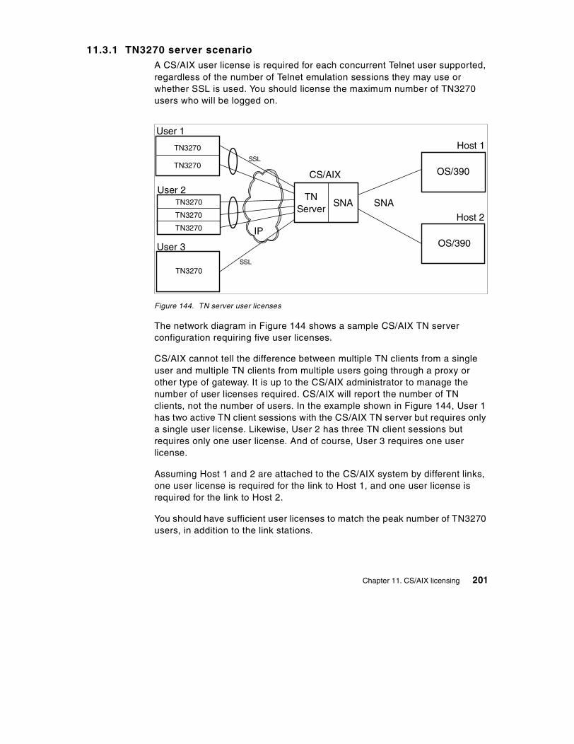
11.3.1 TN3270 server scenarioA CS/AIX user license is required for each concurrent Telnet user supported,regardless of the number of Telnet emulation sessions they may use orwhether SSL is used. You should license the maximum number of TN3270users who will be logged on.
Figure 144. TN server user licenses
The network diagram in Figure 144 shows a sample CS/AIX TN serverconfiguration requiring five user licenses.
CS/AIX cannot tell the difference between multiple TN clients from a singleuser and multiple TN clients from multiple users going through a proxy orother type of gateway. It is up to the CS/AIX administrator to manage thenumber of user licenses required. CS/AIX will report the number of TNclients, not the number of users. In the example shown in Figure 144, User 1has two active TN client sessions with the CS/AIX TN server but requires onlya single user license. Likewise, User 2 has three TN client sessions butrequires only one user license. And of course, User 3 requires one userlicense.
Assuming Host 1 and 2 are attached to the CS/AIX system by different links,one user license is required for the link to Host 1, and one user license isrequired for the link to Host 2.
You should have sufficient user licenses to match the peak number of TN3270users, in addition to the link stations.
CS/AIX
TN3270
TN3270
TN3270
TN3270
TN3270
TN3270
TNServer
User 1
User 2
User 3
Host 1
Host 2
OS/390
OS/390
SNA SNA
IP
SSL
SSL
Chapter 11. CS/AIX licensing 201
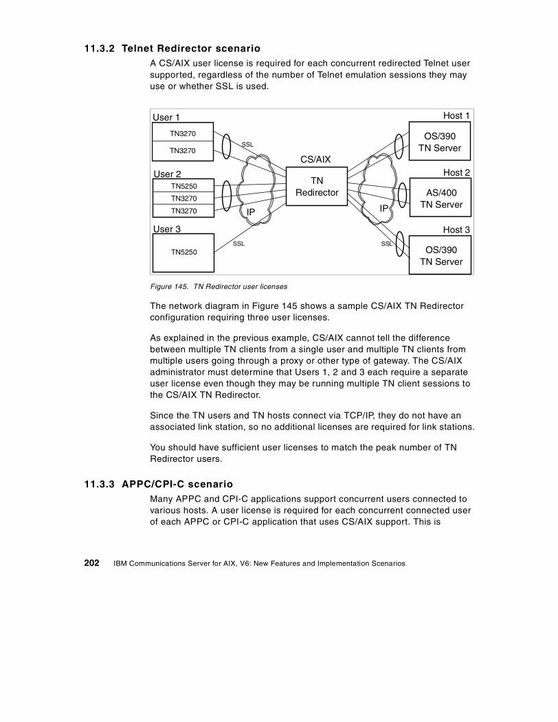
11.3.2 Telnet Redirector scenarioA CS/AIX user license is required for each concurrent redirected Telnet usersupported, regardless of the number of Telnet emulation sessions they mayuse or whether SSL is used.
Figure 145. TN Redirector user licenses
The network diagram in Figure 145 shows a sample CS/AIX TN Redirectorconfiguration requiring three user licenses.
As explained in the previous example, CS/AIX cannot tell the differencebetween multiple TN clients from a single user and multiple TN clients frommultiple users going through a proxy or other type of gateway. The CS/AIXadministrator must determine that Users 1, 2 and 3 each require a separateuser license even though they may be running multiple TN client sessions tothe CS/AIX TN Redirector.
Since the TN users and TN hosts connect via TCP/IP, they do not have anassociated link station, so no additional licenses are required for link stations.
You should have sufficient user licenses to match the peak number of TNRedirector users.
11.3.3 APPC/CPI-C scenarioMany APPC and CPI-C applications support concurrent users connected tovarious hosts. A user license is required for each concurrent connected userof each APPC or CPI-C application that uses CS/AIX support. This is
CS/AIX
TN3270
TN3270
TN5250
TN3270
TN3270
TN5250
TNRedirector
User 1
User 2
User 3
Host 1
Host 2
OS/390TN Server
AS/400TN Server
IP
SSL
SSL
IP
Host 3
OS/390TN Server
SSL
202 IBM Communications Server for AIX, V6: New Features and Implementation Scenarios
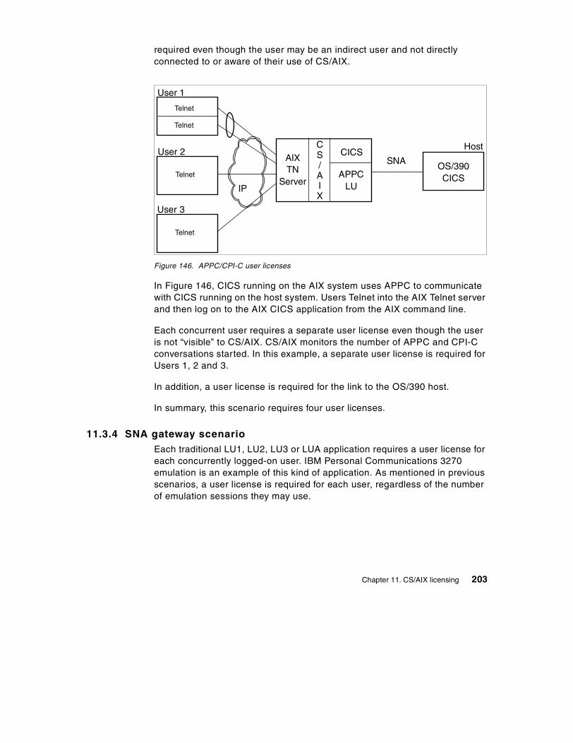
required even though the user may be an indirect user and not directlyconnected to or aware of their use of CS/AIX.
Figure 146. APPC/CPI-C user licenses
In Figure 146, CICS running on the AIX system uses APPC to communicatewith CICS running on the host system. Users Telnet into the AIX Telnet serverand then log on to the AIX CICS application from the AIX command line.
Each concurrent user requires a separate user license even though the useris not “visible” to CS/AIX. CS/AIX monitors the number of APPC and CPI-Cconversations started. In this example, a separate user license is required forUsers 1, 2 and 3.
In addition, a user license is required for the link to the OS/390 host.
In summary, this scenario requires four user licenses.
11.3.4 SNA gateway scenarioEach traditional LU1, LU2, LU3 or LUA application requires a user license foreach concurrently logged-on user. IBM Personal Communications 3270emulation is an example of this kind of application. As mentioned in previousscenarios, a user license is required for each user, regardless of the numberof emulation sessions they may use.
CICS
Telnet
Telnet
Telnet
User 1
User 2Host
OS/390CICS
IP
AIXTN
Server
CS/AIX
APPCLU
SNA
Telnet
User 3
Chapter 11. CS/AIX licensing 203
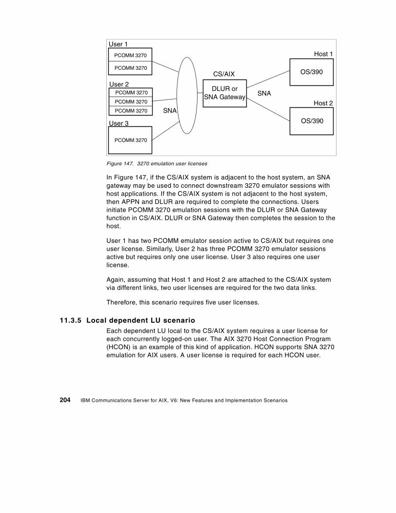
Figure 147. 3270 emulation user licenses
In Figure 147, if the CS/AIX system is adjacent to the host system, an SNAgateway may be used to connect downstream 3270 emulator sessions withhost applications. If the CS/AIX system is not adjacent to the host system,then APPN and DLUR are required to complete the connections. Usersinitiate PCOMM 3270 emulation sessions with the DLUR or SNA Gatewayfunction in CS/AIX. DLUR or SNA Gateway then completes the session to thehost.
User 1 has two PCOMM emulator session active to CS/AIX but requires oneuser license. Similarly, User 2 has three PCOMM 3270 emulator sessionsactive but requires only one user license. User 3 also requires one userlicense.
Again, assuming that Host 1 and Host 2 are attached to the CS/AIX systemvia different links, two user licenses are required for the two data links.
Therefore, this scenario requires five user licenses.
11.3.5 Local dependent LU scenarioEach dependent LU local to the CS/AIX system requires a user license foreach concurrently logged-on user. The AIX 3270 Host Connection Program(HCON) is an example of this kind of application. HCON supports SNA 3270emulation for AIX users. A user license is required for each HCON user.
CS/AIX
PCOMM 3270
DLUR orSNA Gateway
User 1
User 2
User 3
Host 1
Host 2
OS/390
OS/390
SNA
PCOMM 3270
PCOMM 3270
PCOMM 3270
PCOMM 3270
PCOMM 3270
SNA
204 IBM Communications Server for AIX, V6: New Features and Implementation Scenarios
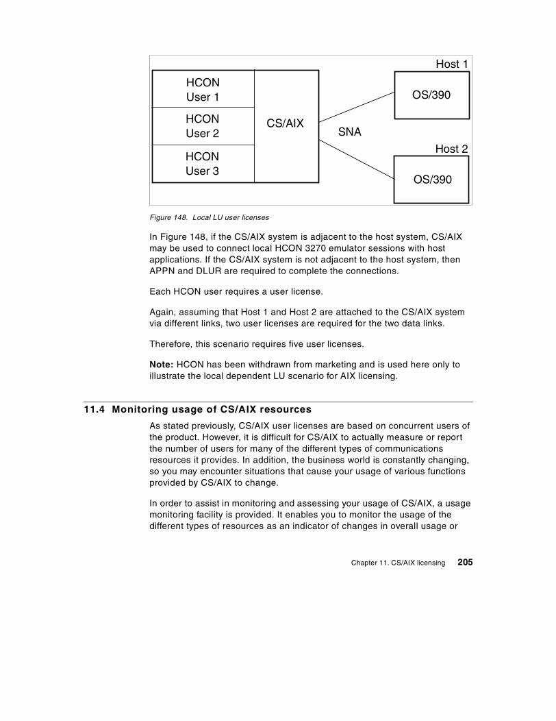
Figure 148. Local LU user licenses
In Figure 148, if the CS/AIX system is adjacent to the host system, CS/AIXmay be used to connect local HCON 3270 emulator sessions with hostapplications. If the CS/AIX system is not adjacent to the host system, thenAPPN and DLUR are required to complete the connections.
Each HCON user requires a user license.
Again, assuming that Host 1 and Host 2 are attached to the CS/AIX systemvia different links, two user licenses are required for the two data links.
Therefore, this scenario requires five user licenses.
Note: HCON has been withdrawn from marketing and is used here only toillustrate the local dependent LU scenario for AIX licensing.
11.4 Monitoring usage of CS/AIX resources
As stated previously, CS/AIX user licenses are based on concurrent users ofthe product. However, it is difficult for CS/AIX to actually measure or reportthe number of users for many of the different types of communicationsresources it provides. In addition, the business world is constantly changing,so you may encounter situations that cause your usage of various functionsprovided by CS/AIX to change.
In order to assist in monitoring and assessing your usage of CS/AIX, a usagemonitoring facility is provided. It enables you to monitor the usage of thedifferent types of resources as an indicator of changes in overall usage or
CS/AIX
HCONUser 1
HCONUser 2
HCONUser 3
Host 1
Host 2
OS/390
OS/390
SNA
Chapter 11. CS/AIX licensing 205
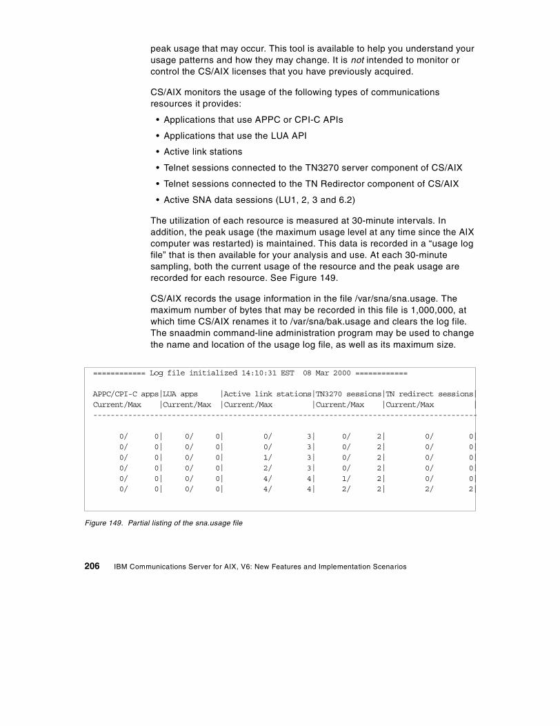
peak usage that may occur. This tool is available to help you understand yourusage patterns and how they may change. It is not intended to monitor orcontrol the CS/AIX licenses that you have previously acquired.
CS/AIX monitors the usage of the following types of communicationsresources it provides:
• Applications that use APPC or CPI-C APIs
• Applications that use the LUA API
• Active link stations
• Telnet sessions connected to the TN3270 server component of CS/AIX
• Telnet sessions connected to the TN Redirector component of CS/AIX
• Active SNA data sessions (LU1, 2, 3 and 6.2)
The utilization of each resource is measured at 30-minute intervals. Inaddition, the peak usage (the maximum usage level at any time since the AIXcomputer was restarted) is maintained. This data is recorded in a “usage logfile” that is then available for your analysis and use. At each 30-minutesampling, both the current usage of the resource and the peak usage arerecorded for each resource. See Figure 149.
CS/AIX records the usage information in the file /var/sna/sna.usage. Themaximum number of bytes that may be recorded in this file is 1,000,000, atwhich time CS/AIX renames it to /var/sna/bak.usage and clears the log file.The snaadmin command-line administration program may be used to changethe name and location of the usage log file, as well as its maximum size.
Figure 149. Partial listing of the sna.usage file
============ Log file initialized 14:10:31 EST 08 Mar 2000 ============
APPC/CPI-C apps|LUA apps |Active link stations|TN3270 sessions|TN redirect sessions|Current/Max |Current/Max |Current/Max |Current/Max |Current/Max |----------------------------------------------------------------------------------------
0/ 0| 0/ 0| 0/ 3| 0/ 2| 0/ 0|0/ 0| 0/ 0| 0/ 3| 0/ 2| 0/ 0|0/ 0| 0/ 0| 1/ 3| 0/ 2| 0/ 0|0/ 0| 0/ 0| 2/ 3| 0/ 2| 0/ 0|0/ 0| 0/ 0| 4/ 4| 1/ 2| 0/ 0|0/ 0| 0/ 0| 4/ 4| 2/ 2| 2/ 2|
206 IBM Communications Server for AIX, V6: New Features and Implementation Scenarios
Figure 149 is a partial listing of the contents of the sna.usage log file. It hasbeen truncated on the right. The format of the usage log file is as follows:
• The file is divided into columns, each recording usage of a particularresource type:
- APPC and CPI-C applications- LUA applications- Active link stations- TN3270 sessions using TN Server- Telnet sessions using TN Redirector- Opens to the SNA device from back-level LU6.2 and LU1-3 applications- Opens to the SNA device from back-level LU0 and G-SNA applications- Data sessions (PLU-SLU sessions)
• Each column shows two figures: the current usage of a particular resourcetype at the time it was recorded, and the peak usage (the maximum usagelevel of the resource type at any time since the computer was restarted).
• Each line in the file represents a “snapshot” of the resource usage at aparticular time, shown by a timestamp at the end of the line (not displayedin Figure 149 due to page width). Usage is recorded at 30-minuteintervals.
CS/AIX provides an additional method for accessing usage information. Youcan get a “snapshot” of the current (right now) and peak usage at any timeusing the following command:
snaadmin query_node_limits
Chapter 11. CS/AIX licensing 207

208 IBM Communications Server for AIX, V6: New Features and Implementation Scenarios
Chapter 12. HTML and docsearch
Product documentation for IBM Communications Server for AIX, Version 6 isdistributed on the product CD as an install image that contains HypertextMarkup Language (HTML) softcopy format. This format enables you to searchor browse for information more easily using hypertext links for relatedinformation. It also makes it easier to share the library across your site.
CS/AIX V6 also includes AIX docsearch indices.
This chapter discusses the installation steps to make this documentationavailable online.
12.1 Setting up CS/AIX HTML documentation
CS/AIX V6 documentation files are in the sna.html.$LANG.data fileset on theinstallation media, where $LANG is one of the supported locales:
en_USJa_JPde_DEes_ESfr_FRit_ITko_KRpt_BRzh_CNzh_TW
The files are unloaded to the directory /usr/share/man/info/$LANG/sna andthe main html file is /usr/share/man/info/$LANG/sna/SNABOOKS.HTM
Not all of the publications were translated for each language. If a particularbook was not translated, the en_US equivalent will be displayed instead.
If you have a Web browser on your CS/AIX system, you can access thepublications with the URL:
file:/usr/share/man/info/$LANG/sna/SNABOOKS.HTM
If you have a Web server on the CS/AIX system, you can access thepublications with the URL:
http://AIXSERVER/doc_link/$LANG/sna/SNABOOKS.HTM
© Copyright IBM Corp. 2000 209
where AIXSERVER is the TCP/IP hostname or address.
If the Web server cannot find the file, create a logical link from the Webserver's public directory to the /usr/share/man/info directory. For example:
ln -fs /usr/HTTPServer/htdocs/doc_link/usr/share/man/info
This link will have been already created if you have configured the AIXdocsearch service.
In addition to the HTML files, CS/AIX also ships the search indices for use bythe AIX docsearch service. These indices are in thesna.html.$LANG.docsearch fileset.
The AIX docsearch service is configured with:
smit web_configure
Select the option on that SMIT panel titled:
Change Documentation and Search Server
Once the search server has been configured, you can use the URL:
http://AIXSERVER/cgi-bin/ds_form?lang=$LANG
to search the CS/AIX manuals for keywords.
For example you can search on define_ip_port to find all the places thatstring appears in the CS/AIX publications.
210 IBM Communications Server for AIX, V6: New Features and Implementation Scenarios

Part 5. Application development
© Copyright IBM Corp. 2000 211

212 IBM Communications Server for AIX, V6: New Features and Implementation Scenarios

Chapter 13. 64-bit SNA applications
IBM Communications Server for AIX, Version 6 introduces support for 64-bitapplications when running with AIX V4.3. Applications written to the APIsintroduced in CS/AIX V5 (LUA, NOF, APPC, CPI-C, CSV, MS) may becompiled and linked to run in either 32-bit or 64-bit mode. Applications thatuse the jCPI-C API or the older CS/AIX V4 APIs do not support 64-bit mode.
13.1 Requirements for 64-bit support
IBM AIX V4.3.2 ML2 or later is required if you intend to compile, link orexecute applications using CS/AIX APIs in 64-bit mode. 64-bit applicationsmay be compiled and linked on an AIX 32-bit machine, but they must beexecuted on an AIX 64-bit machine.
The AIX bos.64bit option must be installed. bos.64bit is part of the AIX baseoperating system. AIX 64-bit support is configured using the command smitload64bit.
64-bit support within AIX 4.3 also requires the latest data link control filesets.Depending on your specific CS/AIX configuration, you may require at leastone of the following filesets at the level indicated:
Table 2. 64-bit fileset requirements
All bos.dlc filesets except sna.dlcchannel and sna.dlcmpc are provided aspart of the bos.dlc.usr package in the AIX base operating system.
Link Station Type Fileset Level
Token-ring bos.dlc.token 4.3.3.11
Standard Ethernet bos.dlc.ether 4.3.3.11
802.3 Ethernet bos.dlc.8023 4.3.3.11
X.25 bos.dlc.qllcsx25.comio
4.3.3.11.1.5.6
SDLC bos.dlc.sdlc 4.3.3.11
FDDI bos.dlc.fddi 4.3.3.11
CDLC Channel sna.dlcchannel 6.0.0.0
MPC Channel sna.dlcmpc 6.0.0.0
© Copyright IBM Corp. 2000 213
The latest level for all these filesets may be downloaded from the followingURL:
http://service.software.ibm.com/cgi-bin/support/rs6000.support/downloads
It is possible to have a CS/AIX configuration that does not require any filesetto be installed:
• Applications that use HPR/IP (Enterprise Extender)
• Applications that use APPC over IP
• U-shaped sessions (stays in the RS/6000 box)
• An application that uses one of the APIs that do not leave the box such asa NOF or CSV application
13.2 64-bit architecture and benefits
From an operation point of view, an architecture is said to be 64-bit when:
• It can handle 64-bit-long data. In other words, a contiguous block of 64 bits(8 bytes) in memory is defined as one of the elementary units that theCPU can handle. This means that the instruction set includes instructionsfor moving 64-bit-long data and instructions for performing arithmeticoperations on 64-bit-long integers.
• It generates 64-bit-long addresses, both as effective addresses (theaddresses generated and used by machine instructions) and as physicaladdresses (those that address the memory cards plugged into themachine memory slots). Individual processor implementations maygenerate shorter physical addresses, but the architecture must support64-bit addresses.
The distinguishing technical features and benefits of 64-bit computing ascontrasted to 32-bit computing are:
• 64-bit integer computation, using hardware with 64-bit general purposeregisters
• Large file support
• Large application virtual address spaces
• Large physical memory support
13.2.1 64-bit integer computationNative 64-bit integer computation is provided by 64-bit hardware, and utilizedby programs computing on 64-bit data types. While there are some
214 IBM Communications Server for AIX, V6: New Features and Implementation Scenarios

specialized applications that need to do computation on integer numberslarger than 232, the key benefit of this capability is in performing arithmeticoperations on pointers in 64-bit programs. Floating point computation alreadyincludes 64-bit precision on all RS/6000 systems.
13.2.2 Large file supportThe ability to create and maintain very large file systems is increasinglyimportant for many users. In particular, data warehousing applications, andscientific and multimedia applications frequently require this support.
The ability to address data in files larger that 2 GB (32-bit addresses)requires that a program be able to specify file offsets larger than a 32-bitnumber. This capability is generally considered to be a 64-bit computingfunction even though it does not require 64-bit hardware support. AIX Version4.2 provided this capability for 32-bit programs, and AIX Version 4.3 providesit for 64-bit programs as well. Since it does not depend on 64-bit hardware,this function can be used on any RS/6000 system running the appropriaterelease of AIX.
There is, however, synergy between large file support and 64-bit hardwarecapabilities, in that a 64-bit program can have much larger portions of 64-bitfiles in its address space, as well as in system memory, at one time, than a32-bit system could provide.
13.2.3 Large application virtual address spacesIn 32-bit systems, an individual program, or process, may typically havebetween 2 GB and 4 GB of virtual address space for its own use to containinstructions and data. With 64-bit computing, applications may run in a 64-bitaddress space, where an individual program’s addressability becomesmeasured in terabytes (TB). Types of applications that currently understandhow to exploit this opportunity include the following:
• Some database management programs use a large address space forscalability, in order to maintain very large data buffers in memory, reducingthe amount of I/O they need to perform. Using a large address space, theycan supply data to client applications at the pace needed to sustain thehigh transaction rate potential afforded by many of the new processors inthe industry.
• In certain cases, database management programs or customerapplications may benefit from keeping an entire database or large fileimmediately accessible in memory. Read-only data lends itself most
Chapter 13. 64-bit SNA applications 215
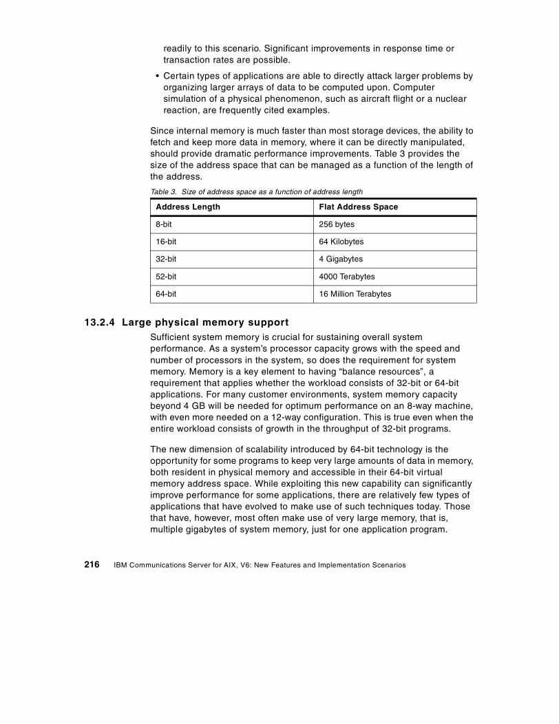
readily to this scenario. Significant improvements in response time ortransaction rates are possible.
• Certain types of applications are able to directly attack larger problems byorganizing larger arrays of data to be computed upon. Computersimulation of a physical phenomenon, such as aircraft flight or a nuclearreaction, are frequently cited examples.
Since internal memory is much faster than most storage devices, the ability tofetch and keep more data in memory, where it can be directly manipulated,should provide dramatic performance improvements. Table 3 provides thesize of the address space that can be managed as a function of the length ofthe address.
Table 3. Size of address space as a function of address length
13.2.4 Large physical memory supportSufficient system memory is crucial for sustaining overall systemperformance. As a system’s processor capacity grows with the speed andnumber of processors in the system, so does the requirement for systemmemory. Memory is a key element to having “balance resources”, arequirement that applies whether the workload consists of 32-bit or 64-bitapplications. For many customer environments, system memory capacitybeyond 4 GB will be needed for optimum performance on an 8-way machine,with even more needed on a 12-way configuration. This is true even when theentire workload consists of growth in the throughput of 32-bit programs.
The new dimension of scalability introduced by 64-bit technology is theopportunity for some programs to keep very large amounts of data in memory,both resident in physical memory and accessible in their 64-bit virtualmemory address space. While exploiting this new capability can significantlyimprove performance for some applications, there are relatively few types ofapplications that have evolved to make use of such techniques today. Thosethat have, however, most often make use of very large memory, that is,multiple gigabytes of system memory, just for one application program.
Address Length Flat Address Space
8-bit 256 bytes
16-bit 64 Kilobytes
32-bit 4 Gigabytes
52-bit 4000 Terabytes
64-bit 16 Million Terabytes
216 IBM Communications Server for AIX, V6: New Features and Implementation Scenarios
13.3 Compatibility and interoperability
If you consider the benefits of 64-bit computing in the context of a customerwith an established information technology investment based on existing32-bit system implementations, it seems obvious that 64-bit computing willcomplement 32-bit computing in different ways for different customers.Customers will move at a wide range of speeds into exploitation of the variouselements of 64-bit programs. The 64-bit virtual address space is of value tospecific applications that can exploit it; other applications are best left as32-bit programs, but must be able to coexist and interoperate with theselective, but typically strategic, applications that are ported to 64-bit.
There is no single dimension to scalability. Some environments can grow withmore 32-bit processes running on larger SMP systems. In many serverenvironments, a critical server application must also scale with systemthroughput, using larger files and/or bigger data buffers large enough todemand a 64-bit address space. Customer investment protection assistance,combined with customer flexibility to implement 64-bit technology as theirenvironment demands it, leads to the requirement that 64-bit systems shouldsupport 32-bit binary compatibility, and that 32-bit and 64-bit environmentsmust coexist and cooperate and share resources as easily as 32-bit programstraditionally have in the past.
13.3.1 64-bit hardware compatibilityRS/6000 64-bit products are built upon the PowerPC processor architecture,which defines both 64-bit and 32-bit processors, the latter a subset of theformer. In practical terms, this means a PowerPC 64-bit processor is a propersuperset of a 32-bit processor, allowing a 64-bit processor to run 32-bitprograms the same way the programs run on a 32-bit processor. Hardware32-bit binary compatibility is native; it does not rely on high-overheademulation techniques.
Hardware support for 32-bit binary compatibility is the first step in achieving32-bit application binary compatibility on 64-bit systems under AIX V4.3. Thishardware compatibility is also used by AIX itself, as a building block inmaintaining binary compatibility for existing device drivers and kernelextensions running on 64-bit systems.
13.3.2 64-bit software compatibilityThe 64-bit execution environment for application processes is anupward-compatible addition to AIX capability, not a replacement for existing32-bit function. The design chosen for 64-bit AIX allows existing 32-bit
Chapter 13. 64-bit SNA applications 217
applications to run with 64-bit applications with no changes, thus protectingthe investment users have made in their current applications. Users can takeadvantage of the features of 64-bit AIX when business needs dictate.
AIX 64-bit support is intended to be run on 64-bit hardware systems, notsimply any system containing a 64-bit PowerPC processor. A 64-bit hardwaresystem is one that is based on the RS/6000 architecture and identifies 64-bitproperties for the processor(s) and processor host bridges (PHBs) inconfigurations with memory addressing greater than 32 bits.
For AIX, and the applications that run on AIX, the 64-bit PowerPCs have twoimportant attributes. They are very fast when running as 32-bit processors,and they offer the opportunity of running a 64-bit environment. AIX V4.3exploits these attributes separately. There are two different executionenvironments in AIX V4.3, the 32-bit execution environment and the 64-bitexecution environment. These two environments are only available for 64-bithardware. There is no 64-bit execution environment on 32-bit hardware.
Generally, the AIX V4.3 kernel remains 32-bit, and only selected parts, suchas the Virtual Memory Manager, are upgraded to be aware of the 64-bitaddress space. This means that the number of AIX kernels remains at two(uniprocessor and multiprocessor).
13.4 CS/AIX and 64-bit applications
What does all this mean to you as an application developer in the CS/AIXenvironment? If you choose to develop applications using the newer APIs,those applications can be compiled and linked as either 32-bit or 64-bitapplications. A mixture of 32-bit and 64-bit APPC or CPI-C applications canbe run on the same machine and communicate with other 32-bit or 64-bitapplications on the same or different machines.
Applications that use the 64-bit APIs can run only on 64-bit hardware, whileapplications that use the 32-bit APIs can run on either 32-bit or 64-bithardware.
In addition, 64-bit applications can be written, compiled and linked on an AIX4.3 32-bit machine (development system), and then executed on an AIX 4.364-bit machine (production system).
13.4.1 Sample applicationsCS/AIX does not ship any sample applications that explicitly use 64-bitcapabilities. However, using the instructions in the appropriate manual, you
218 IBM Communications Server for AIX, V6: New Features and Implementation Scenarios
can compile the APPC, CPI-C and LUA sample programs as 64-bit. Thesample programs are in /usr/lib/sna/samples.
The APPC sample programs are “asample1.c” and “asample2.c”.
The CPI-C sample programs are “csample1.c” and “asample2.c”.
The LUA sample program is “lsample.c”.
Following are the commands that show how to configure, compile, and runthe CPI-C sample programs in 64-bit mode. The steps below assume this is anew configuration and that the CPI-C programs will be run in a U-shapedsession (not over a real physical link) where both the TPs are in the sameCS/AIX node.
1. Make sure the software pre-reqs are installed:
lslpp -h bos.64bit sna.rte64
2. Compile the sample CPI-C programs using the correct libraries and flagsfor 64-bit mode:
cd /usr/lib/sna/samples
cc -o csample1 -I /usr/include/sna \
-bimport:/usr/lib/sna/cpic64.exp -q64 csample1.c
cc -o csample2 -I /usr/include/sna \
-bimport:/usr/lib/sna/cpic64.exp -q64 csample2.c
3. Confirm that the executables are 64-bit programs:
file csample1 csample2
4. Set the permissions for the target TP:
chown root csample2
chmod +s csample2
5. Configure the CS/AIX node:
snaadmin define_node, cp_alias=AIXCP, fqcp_name=NETID.AIXCP
snaadmin define_mode, mode_name=LOCMODE
snaadmin define_local_lu, lu_name=TPLU1, lu_alias=TPLU1
snaadmin define_local_lu, lu_name=TPLU2, lu_alias=TPLU2
snaadmin define_cpic_side_info, sym_dest_name=CPICTEST, \
lu_alias=TPLU1, partner_lu_name=NETID.TPLU2, \
Chapter 13. 64-bit SNA applications 219

mode_name=LOCMODE, tp_name=TPNAME2
snaadmin define_tp, tp_name=TPNAME2
snaadmin define_tp_load_info, tp_name=TPNAME2, userid=root, \
path=/usr/lib/sna/samples/csample2, type=QUEUED, \
env=APPCTPN=TPNAME2, env=APPCLLU=TPLU2
6. Start the CS/AIX node:
snaadmin init_node
7. Run the local TP:
export APPCLLU=TPLU1
export APPCTPN=TPNAME1
./csample1 /etc/hosts
Q
220 IBM Communications Server for AIX, V6: New Features and Implementation Scenarios

Chapter 14. Java CPI-C
IBM Communications Server for AIX, Version 6 has been enhanced to enablecustomers to take advantage of Java as an efficient application developmenttool to more easily bridge the gap between the Internet and critical legacydata applications.
In addition to the standard C-language CPI-C API, CS/AIX now includes aCPI-C API for use by Java applications.
14.1 Overview
Java CPI-C (jCPI-C) is a new API for CS/AIX V6 that allows you to write Javaprograms that make CPI-C calls. These programs can be used as any of theLU6.2 Transaction Program (TP) types:
• Invoking TP
• Invokable TP
• Operator started TP
An invoking TP is sometimes called a client TP or a local TP. APING is anexample of this type of TP.
An invokable TP is sometimes called a server TP or a remote TP. It has anentry in the /etc/sna/sna_tps file and is started automatically by CS/AIX whenan ATTACH arrives with that TP name. AFTPD is an example of this type ofTP.
An operator started TP is also sometimes called a server TP or a remote TP.The difference is that it is started by a user or application and not by CS/AIXand it has to be ready and waiting when the ATTACH arrives.
Not all of the CPI-C calls are available in the Java environment. For example,the nonblocking mode is not available in Java CPI-C. See the CS/AIX V6CPI-C Programmer's Guide, SC31-8591-01, for more details about whichcalls are valid.
CS/AIX V6 ships a sample Java CPI-C program called JPing which shows aninvoking TP, similar in function to APING. The source code for the JPingsample is in the directory:
/usr/lib/sna/samples
© Copyright IBM Corp. 2000 221

The parameters for JPing are different from those for APING. Here is theusage statement:
JPing [-s symb_dest] [-n num_iter] [-d data_len]
Here are steps for using JPing on a U-shaped (loopback) session:
1. Must have Java 1.1.6, 1.1.8, 1.2.2, or 1.3.0 installed:
lslpp -h 'Java*.rte.*'
2. Create a cpic side info definition:
snaadmin define_cpic_side_info, sym_dest_name=LOOPBACK, \partner_lu_name=NETID.AIXCP, mode_name='#INTER', \tp_name=APINGD
where NETID.AIXCP is the fully-qualified CP name of the CS/AIX node.
3. Set up the Java environment:
a. For Java 1.1.6 or 1.1.8 do:
export LIBPATH=$LIBPATH:/usr/lib/snaexport CLASSPATH=/usr/lib/sna/samples:/usr/lib/sna/cpic.jar
b. For Java 1.2.2 do:
export PATH=/usr/java_dev2/jre/sh:/usr/java_dev2/sh:$PATHexport LIBPATH=$LIBPATH:/usr/lib/snaexport CLASSPATH=/usr/lib/sna/samples:/usr/lib/sna/cpic.jar
c. For Java 1.3.0 do:
export PATH=/usr/java130/jre/bin:/usr/java130/bin:$PATHexport LIBPATH=$LIBPATH:/usr/lib/snaexport CLASSPATH=/usr/lib/sna/samples:/usr/lib/sna/cpic.jar
4. Check the java environment:
java -version
5. Run the JPing program:
a. For Java 1.1.6, 1.1.8, or 1.2.2 do:
java JPing -s LOOPBACK
b. For Java 1.3.0 do:
java -Djava.library.path=$LIBPATH JPing -s LOOPBACK
For an invokable TP you would need to create an /etc/sna/sna_tps entrysimiliar to this:
[JPINGD]
222 IBM Communications Server for AIX, V6: New Features and Implementation Scenarios

LUALIAS = ""DESCRIPTION = ""USERID = guestGROUP = ""TIMEOUT = 5TYPE = NON-QUEUEDSTYLE = EXTENDEDPATH = /usr/bin/javaARGUMENTS = JPINGDSTDOUT = /tmp/stdoutSTDERR = /tmp/stderrENV = CLASSPATH=/usr/lib/sna/cpic.jar:/u/jpingdENV = LIBPATH=/usr/lib/sna:/usr/jdk_base/lib/aix/native_threads
This example is for Java 1.1.6 or 1.1.8 and assumes the .class file for theJava CPI-C TP is in /u/jpingd. Changes would have to be made for Java 1.2.2or 1.3.0 or more complex TPs.
Chapter 14. Java CPI-C 223

224 IBM Communications Server for AIX, V6: New Features and Implementation Scenarios

Appendix A. Special notices
This publication is intended to help AIX systems and network administratorsto plan, install and configure the new features and functions included in IBMCommunications Server for AIX, Version 6. The information in this publicationis not intended as the specification of any programming interfaces that areprovided by CS/AIX, V6. See the PUBLICATIONS section of the IBMProgramming Announcement for IBM Communications Server for AIX,Version 6 for more information about what publications are considered to beproduct documentation.
References in this publication to IBM products, programs or services do notimply that IBM intends to make these available in all countries in which IBMoperates. Any reference to an IBM product, program, or service is notintended to state or imply that only IBM's product, program, or service may beused. Any functionally equivalent program that does not infringe any of IBM'sintellectual property rights may be used instead of the IBM product, programor service.
Information in this book was developed in conjunction with use of theequipment specified, and is limited in application to those specific hardwareand software products and levels.
IBM may have patents or pending patent applications covering subject matterin this document. The furnishing of this document does not give you anylicense to these patents. You can send license inquiries, in writing, to the IBMDirector of Licensing, IBM Corporation, North Castle Drive, Armonk, NY10504-1785.
Licensees of this program who wish to have information about it for thepurpose of enabling: (i) the exchange of information between independentlycreated programs and other programs (including this one) and (ii) the mutualuse of the information which has been exchanged, should contact IBMCorporation, Dept. 600A, Mail Drop 1329, Somers, NY 10589 USA.
Such information may be available, subject to appropriate terms andconditions, including in some cases, payment of a fee.
The information contained in this document has not been submitted to anyformal IBM test and is distributed AS IS. The use of this information or theimplementation of any of these techniques is a customer responsibility anddepends on the customer's ability to evaluate and integrate them into thecustomer's operational environment. While each item may have beenreviewed by IBM for accuracy in a specific situation, there is no guarantee
© Copyright IBM Corp. 2000 225

that the same or similar results will be obtained elsewhere. Customersattempting to adapt these techniques to their own environments do so at theirown risk.
Any pointers in this publication to external Web sites are provided forconvenience only and do not in any manner serve as an endorsement ofthese Web sites.
The following terms are trademarks of the International Business MachinesCorporation in the United States and/or other countries:
The following terms are trademarks of other companies:
Tivoli, Manage. Anything. Anywhere.,The Power To Manage., Anything.Anywhere.,TME, NetView, Cross-Site, Tivoli Ready, Tivoli Certified, PlanetTivoli, and Tivoli Enterprise are trademarks or registered trademarks of TivoliSystems Inc., an IBM company, in the United States, other countries, or both.In Denmark, Tivoli is a trademark licensed from Kjøbenhavns Sommer - TivoliA/S.
C-bus is a trademark of Corollary, Inc. in the United States and/or othercountries.
Java and all Java-based trademarks and logos are trademarks or registeredtrademarks of Sun Microsystems, Inc. in the United States and/or othercountries.
Microsoft, Windows, Windows NT, and the Windows logo are trademarks ofMicrosoft Corporation in the United States and/or other countries.
PC Direct is a trademark of Ziff Communications Company in the UnitedStates and/or other countries and is used by IBM Corporation under license.
AIX AnyNetAPPN AS/400CICS CUAES/9000 ESCONIBM Micro ChannelOS/2 OS/390RISC System/6000 RS/6000S/390 SecureWaySP TCSVTAM WebSphereLotus DominoTivoli NetView
226 IBM Communications Server for AIX, V6: New Features and Implementation Scenarios

ActionMedia, LANDesk, MMX, Pentium and ProShare are trademarks of IntelCorporation in the United States and/or other countries.
UNIX is a registered trademark in the United States and other countrieslicensed exclusively through The Open Group.
SET, SET Secure Electronic Transaction, and the SET Logo are trademarksowned by SET Secure Electronic Transaction LLC.
Other company, product, and service names may be trademarks or servicemarks of others.
Appendix A. Special notices 227

228 IBM Communications Server for AIX, V6: New Features and Implementation Scenarios
Appendix B. Related publications
The publications listed in this section are considered particularly suitable for amore detailed discussion of the topics covered in this redbook.
B.1 IBM Redbooks
For information on ordering these publications see “How to get IBMRedbooks” on page 231.
• IBM eNetwork Communications Server for AIX: Understanding andMigrating to Version 5 (Part 1): Configuration and New Features,SG24-5215
• IBM eNetwork Communications Server for AIX: Understanding andMigrating to Version 5: Part 2 - Performance, SG24-2136
B.2 IBM Redbooks collections
Redbooks are also available on the following CD-ROMs. Click the CD-ROMsbutton at http://www.redbooks.ibm.com/ for information about all theCD-ROMs offered, updates and formats.
B.3 Other resources
These publications are also relevant as further information sources:
• IBM eNetwork Communications Server for AIX Quick Beginnings Version6, GC31-8583
CD-ROM Title Collection KitNumber
System/390 Redbooks Collection SK2T-2177
IBM Networking Redbooks Collection SK2T-6022
Transaction Processing and Data Management Redbooks Collection SK2T-8038
Lotus Redbooks Collection SK2T-8039
Tivoli Redbooks Collection SK2T-8044
AS/400 Redbooks Collection SK2T-2849
Netfinity Hardware and Software Redbooks Collection SK2T-8046
RS/6000 Redbooks Collection (BkMgr) SK2T-8040
RS/6000 Redbooks Collection (PDF Format) SK2T-8043
Application Development Redbooks Collection SK2T-8037
IBM Enterprise Storage and Systems Management Solutions SK3T-3694
© Copyright IBM Corp. 2000 229
• IBM eNetwork Communications Server for AIX Migration Guide Version 6,SC31-8585
• IBM eNetwork Communications Server for AIX Administration GuideVersion 6, SC31-8586
• IBM eNetwork Communications Server for AIX Administration CommandReference Version 6, SC31-8587
• IBM SecureWay Communications Server for AIX Channel ConnectivityUser’s Guide Version 6, SC31-8219
• IBM eNetwork Communications Server for AIX CPI-C Programmer’s GuideVersion 6, SC31-8591
• IBM eNetwork Communications Server for AIX APPC Application SuiteVersion 6, SC31-8596
• IBM eNetwork Communications Server for AIX Diagnostics Guide Version6, SC31-8588
• S/390 ESCON Channel PCI Adapter User's Guide, SC23-4232
• PCI Adapter Placement Reference, SA38-0538
• OS/390 SecureWay Communications Server: SNA Resource DefinitionReference, SC31-8565
• OS/390 SecureWay Communications Server: SNA NetworkImplementation, SC31-8563
B.4 Referenced Web sites
These Web sites are also relevant as further information sources:
• http://www.ibm.com/software/network/commserver/
Communications Server product home page
• http://www.ibm.com/software/network/commserver/support/
Communications Server service and support page
• http://www.ibm.com/software/network/library/whitepapers/
IBM networking white papers
• http://www.ibm.com/software/network/commserver/library/
Communications Server white papers, documentation, and brochures
230 IBM Communications Server for AIX, V6: New Features and Implementation Scenarios
How to get IBM Redbooks
This section explains how both customers and IBM employees can find out about IBM Redbooks,redpieces, and CD-ROMs. A form for ordering books and CD-ROMs by fax or e-mail is also provided.
• Redbooks Web Site http://www.redbooks.ibm.com/
Search for, view, download, or order hardcopy/CD-ROM Redbooks from the Redbooks Web site.Also read redpieces and download additional materials (code samples or diskette/CD-ROM images)from this Redbooks site.
Redpieces are Redbooks in progress; not all Redbooks become redpieces and sometimes just a fewchapters will be published this way. The intent is to get the information out much quicker than theformal publishing process allows.
• E-mail Orders
Send orders by e-mail including information from the IBM Redbooks fax order form to:
• Telephone Orders
• Fax Orders
This information was current at the time of publication, but is continually subject to change. The latestinformation may be found at the Redbooks Web site.
In United StatesOutside North America
e-mail [email protected] information is in the “How to Order” section at this site:http://www.elink.ibmlink.ibm.com/pbl/pbl
United States (toll free)Canada (toll free)Outside North America
1-800-879-27551-800-IBM-4YOUCountry coordinator phone number is in the “How to Order”section at this site:http://www.elink.ibmlink.ibm.com/pbl/pbl
United States (toll free)CanadaOutside North America
1-800-445-92691-403-267-4455Fax phone number is in the “How to Order” section at this site:http://www.elink.ibmlink.ibm.com/pbl/pbl
IBM employees may register for information on workshops, residencies, and Redbooks by accessingthe IBM Intranet Web site at http://w3.itso.ibm.com/ and clicking the ITSO Mailing List button.Look in the Materials repository for workshops, presentations, papers, and Web pages developedand written by the ITSO technical professionals; click the Additional Materials button. Employees mayaccess MyNews at http://w3.ibm.com/ for redbook, residency, and workshop announcements.
IBM Intranet for Employees
© Copyright IBM Corp. 2000 231

IBM Redbooks fax order form
Please send me the following:
We accept American Express, Diners, Eurocard, Master Card, and Visa. Payment by credit card notavailable in all countries. Signature mandatory for credit card payment.
Title Order Number Quantity
First name Last name
Company
Address
City Postal code
Telephone number Telefax number VAT number
Invoice to customer number
Country
Credit card number
Credit card expiration date SignatureCard issued to
232 IBM Communications Server for AIX, V6: New Features and Implementation Scenarios
Index
Numerics64-bit 213, 214, 215, 216, 217, 218
Aaccess record 37, 42, 58, 61, 65, 66Adaptive Rate-Based 87ANR 86AnyNet 81API 213, 218, 221aping 111, 135APPC 202, 214, 218ARB 87ARB1 88ARB2 89ARTIC 145ATCSTRxx 101, 102, 103audit file 105authentication 34, 38Automatic Network Routing 86
BBase ARB 88branch extender 115, 117, 118, 120, 122branch network node 115BrNN 115, 120, 121
CCertificate Management 25Certificate Revocation List (CRL) 14, 38Certificate Wizard 25certifying authority (CA) 11client authentication 17, 38Command-line administration program 170connection network 118CPI-C 202, 218, 221
DDDDLU 165DDDLU power-off 165directory agent 52, 53, 57DLUR 92, 94, 121, 125, 141docsearch 209, 210Dynamic Definition of Dependent LU 165
© Copyright IBM Corp. 2000
EEE 81, 101, 103Enable load balancing 60encryption 34, 38Enterprise Extender 4, 81, 89, 91, 92, 122, 214ESCON 141, 142, 143, 145, 146, 150, 151, 152
Ggskit.rte 12
HHashing Functions 10HCD 146, 147, 153High Performance Data Traffic 141HPDT 141HPR 81, 92, 117, 118, 142HPR/IP 81, 82, 90, 92, 103, 105, 122, 128, 214HTML 209
IImplicit Links to End Nodes 128inactivity timeout 77IOCP 152, 153IUTSAMEH 102
JJava 221jCPI-C 213, 221JPing 221, 222
KKey Management utility 12, 15, 19
Llicense 205licensing 199load advertisement frequency 60, 62, 67load balancing 54, 55, 58, 60, 66, 72load change threshold 60, 67load factor 60, 61, 67
MMCA 142Motif administration program 169, 172, 187
233

MPC 141, 148MPC group 155, 156, 162MPC+ 123, 141, 142, 143, 144, 148, 149, 158,161multicast 51, 52, 57MultiPath Channel 141MultiPath Channel Plus 141
NNetView 172Network Layer Packet 86network node server 115Network operator facility 171NLP 86NMVT 165NNS 115, 121NOF 171, 214
OOCP 147
PPCI 142, 145PCI adapter 142, 143, 145, 146, 150, 157PCOMM 92PCSGSK 25Perform client authentication 13private key 10public key 10public-key certificate 11Public-Key Encryption 10
RRedirector 33, 34, 35, 36, 43, 46, 47, 200, 202,206, 207Responsive Mode ARB 89RTP 87
Sscope 54, 55, 57, 61, 62, 66, 67, 68, 69SDDLU 165Secure Sockets Layer 3, 9Security level 38Self signed Certificates 16Self-Defining Dependent LU 165Server authentication 17server license 199
service agent 52, 53, 57Service Location Protocol 4, 51Service point command facility 172slot 153, 154SLP 51, 52, 53, 57SMIT 170SNA Channel for AIX 142, 144, 146sna.dlcchannel 143, 146sna.dlcmpc 143, 146sna.usage 206, 207SnaAdmin 173, 176, 181snaadmin 170, 207snakeyman 19SSL 34, 38, 47, 69
certifying authority (CA) 11Public-Key Certificates 10
SSL secure session 13, 14strong security 12Symmetric-Key Encryption 9
TTCP/IP profile 101, 102TDM 120TDU 119, 121Telnet 33, 38TN Redirector 3, 14, 33, 36, 43, 46, 47, 202TN3270 33, 53, 58, 77, 201TN3270E 33, 51TN5250 33Tool bar 177topology database 118, 119, 120Topology Database Manager 119topology database update 119transport resource list element 149Transport Resource List Entry 102, 149TRLE 149trusted certificate authority 16
Uunknown CA 17user agent 52, 53, 57, 69user license 200, 201, 202, 203, 204
VVIPA 100, 102, 103VT 33
234 IBM Communications Server for AIX, V6: New Features and Implementation Scenarios

WWeb Administration program 169, 172, 176Web servers 174well-known CA 16
Xxsnaadmin 35, 58, 78, 158, 170
235

236 IBM Communications Server for AIX, V6: New Features and Implementation Scenarios
© Copyright IBM Corp. 2000 237
IBM Redbooks review
Your feedback is valued by the Redbook authors. In particular we are interested in situations where aRedbook "made the difference" in a task or problem you encountered. Using one of the followingmethods, please review the Redbook, addressing value, subject matter, structure, depth andquality as appropriate.
• Use the online Contact us review redbook form found at ibm.com/redbooks• Fax this form to: USA International Access Code + 1 914 432 8264• Send your comments in an Internet note to [email protected]
Document NumberRedbook Title
SG24-5947-00IBM Communications Server for AIX, V6 New Features andImplementation Scenarios
Review
What other subjects would youlike to see IBM Redbooksaddress?
Please rate your overallsatisfaction:
O Very Good O Good O Average O Poor
Please identify yourself asbelonging to one of thefollowing groups:
O Customer O Business Partner O Solution DeveloperO IBM, Lotus or Tivoli EmployeeO None of the above
Your email address:The data you provide here maybe used to provide you withinformation from IBM or ourbusiness partners about ourproducts, services or activities.
O Please do not use the information collected here for futuremarketing or promotional contacts or other communications beyondthe scope of this transaction.
Questions about IBM’s privacypolicy?
The following link explains how we protect your personal information.ibm.com/privacy/yourprivacy/


(0.5” spine)0.475”<->0.875”
250 <-> 459 pages
IBM Com
munications Server for AIX, V6 N
ew Features and Im
plementation Scenarios


®
SG24-5947-00 ISBN 0738417874
INTERNATIONAL TECHNICALSUPPORTORGANIZATION
BUILDING TECHNICALINFORMATION BASED ONPRACTICAL EXPERIENCE
IBM Redbooks are developed by IBM's International Technical Support Organization. Experts from IBM, Customers and Partners from around the world create timely technical information based on realistic scenarios. Specific recommendations are provided to help you implement IT solutions more effectively in your environment.
For more information:ibm.com/redbooks
IBM CommunicationsServer for AIX, V6New Features and Implementation Scenarios
Scenarios for Telnet Redirector, SSL, and Service Location Protocol
Covers SNA features Enterprise Extender, Branch Extender, MPC+
Examples of Web Admin, 64-bit apps and more
This new release of Communications Server for AIX includes many new features and functions that make CS/AIX a more important player in bridging the e-business gap between the Internet and critical legacy data applications. Support for secure TN3270 communications with SSL and load balancing with SLP are critical in ensuring secure and consistent communications with the host. Support for high performance routing, branch network configurations, and channel attachment are significant in that they allow placement of Communications Server anywhere it benefits performance most in the customer's IP or SNA network. This book covers the new features and functions in Communications Server for AIX, Version 6. Each feature is explained. Implementation steps are listed for most features, and sample scenarios are reviewed to give a better understanding of where a feature or function may fit in your networking environment. Guidelines given in this redbook are general. Several scenarios are included, and although actual customer networks most likely will differ, these scenarios serve as examples for customers to develop proper plans to expand or migrate their networks to meet future business requirements. Customers are invited to engage IBM in the planning process.