Embed Size (px)
Citation preview

©Ian Sommerville 2006 Software Engineering, 7th edition. Chapter 14 Slide 1
Object-oriented Design
©Ian Sommerville 2006 Software Engineering, 7th edition. Chapter 14 Slide 2
Object-oriented development
Object-oriented analysis, design and programming are related but distinct.
OOA is concerned with developing an object model of the application domain.
OOD is concerned with developing an object-oriented system model to implement requirements.
OOP is concerned with realising an OOD using an OO programming language such as Java or C++.

©Ian Sommerville 2006 Software Engineering, 7th edition. Chapter 14 Slide 3
Characteristics of OOD
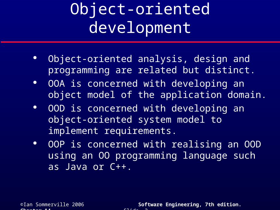
Objects are abstractions of real-world or system entities and manage themselves.
Objects are independent and encapsulate state and representation information.
System functionality is expressed in terms of object services.
Shared data areas are eliminated. Objects communicate by message passing.
Objects may be distributed and may execute sequentially or in parallel.
©Ian Sommerville 2006 Software Engineering, 7th edition. Chapter 14 Slide 4
Interacting objects
state o3
o3:C3
state o4
o4: C4
state o1
o1: C1
state o6
o6: C1
state o5
o5:C5
state o2
o2: C3
ops1() ops3 () ops4 ()
ops3 () ops1 () ops5 ()

©Ian Sommerville 2006 Software Engineering, 7th edition. Chapter 14 Slide 5
Advantages of OOD
Easier maintenance. Objects may be understood as stand-alone entities.
Objects are potentially reusable components. For some systems, there may be an obvious
mapping from real world entities to system objects.

©Ian Sommerville 2006 Software Engineering, 7th edition. Chapter 14 Slide 6
Objects and object classes
Objects are entities in a software system which represent instances of real-world and system entities.
Object classes are templates for objects. They may be used to create objects.
Object classes may inherit attributes and services from other object classes.

©Ian Sommerville 2006 Software Engineering, 7th edition. Chapter 14 Slide 7
Objects and object classes
An object is an entity that has a state and a defined set of operations which operate on that state. The state is represented as a set of object attributes. The operations associated with the object provide services to other objects (clients) which request these services when some computation is required.
Objects are created according to some object class definition. An object class definition serves as a template for objects. It includes declarations of all the attributes and services which should be associated with an object of that class.

©Ian Sommerville 2006 Software Engineering, 7th edition. Chapter 14 Slide 8
The Unified Modeling Language
Several different notations for describing object-oriented designs were proposed in the 1980s and 1990s.
The Unified Modeling Language is an integration of these notations.
It describes notations for a number of different models that may be produced during OO analysis and design.
It is now a de facto standard for OO modelling.
©Ian Sommerville 2006 Software Engineering, 7th edition. Chapter 14 Slide 9
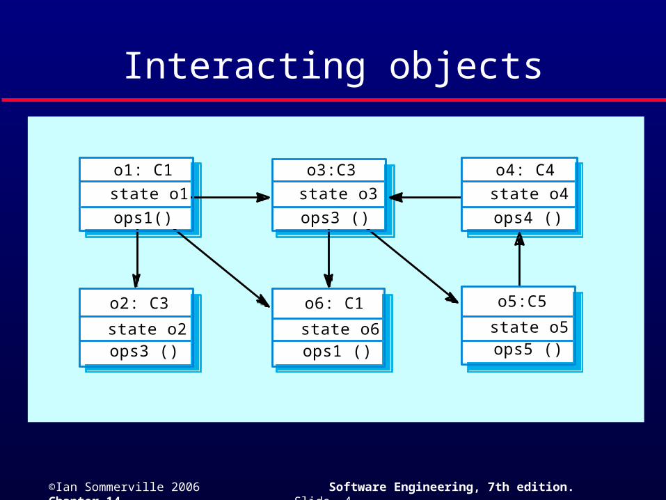
Employee object class (UML)
Employee
name: stringaddress: stringdateOfBirth: DateemployeeNo: integersocialSecurityNo: stringdepartment: Deptmanager: Employeesalary: integerstatus: {current, left, retired}taxCode: integer. . .
join ()leave ()retire ()changeDetails ()
©Ian Sommerville 2006 Software Engineering, 7th edition. Chapter 14 Slide 10
Object communication
Conceptually, objects communicate by message passing.
Messages• The name of the service requested by the calling object;• Copies of the information required to execute the service
and the name of a holder for the result of the service. In practice, messages are often implemented
by procedure calls• Name = procedure name;• Information = parameter list.
©Ian Sommerville 2006 Software Engineering, 7th edition. Chapter 14 Slide 11
Message examples
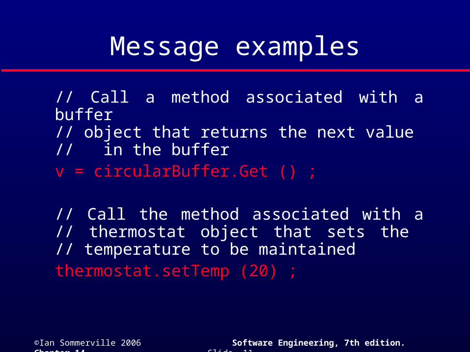
// Call a method associated with a buffer // object that returns the next value // in the buffer
v = circularBuffer.Get () ;
// Call the method associated with a// thermostat object that sets the // temperature to be maintained
thermostat.setTemp (20) ;
©Ian Sommerville 2006 Software Engineering, 7th edition. Chapter 14 Slide 12
Generalisation and inheritance
Objects are members of classes that define attribute types and operations.
Classes may be arranged in a class hierarchy where one class (a super-class) is a generalisation of one or more other classes (sub-classes).
A sub-class inherits the attributes and operations from its super class and may add new methods or attributes of its own.
Generalisation in the UML is implemented as inheritance in OO programming languages.
©Ian Sommerville 2006 Software Engineering, 7th edition. Chapter 14 Slide 13
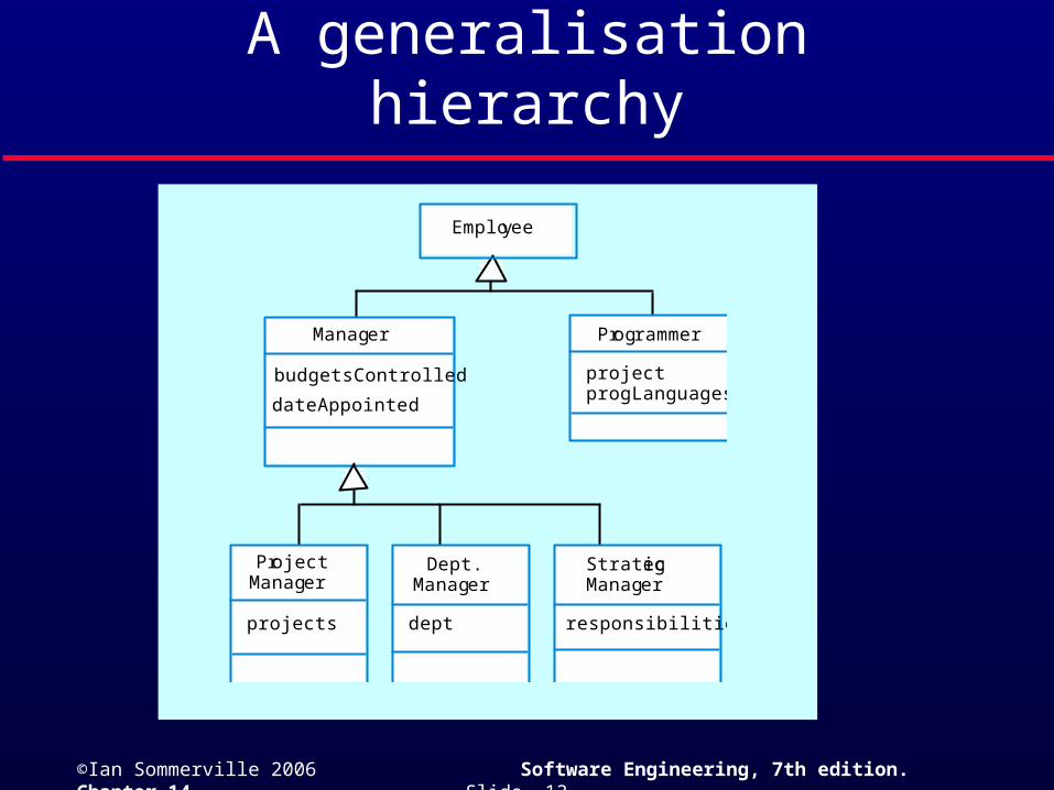
A generalisation hierarchy
Employee
Programmer
projectprogLanguages
Manager
ProjectManager
budgetsControlled
dateAppointed
projects
Dept.Manager
StrategicManager
dept responsibilities
©Ian Sommerville 2006 Software Engineering, 7th edition. Chapter 14 Slide 14
Advantages of inheritance
It is an abstraction mechanism which may be used to classify entities.
It is a reuse mechanism at both the design and the programming level.
The inheritance graph is a source of organisational knowledge about domains and systems.
©Ian Sommerville 2006 Software Engineering, 7th edition. Chapter 14 Slide 15
Problems with inheritance
Object classes are not self-contained. they cannot be understood without reference to their super-classes.
Designers have a tendency to reuse the inheritance graph created during analysis. Can lead to significant inefficiency.
The inheritance graphs of analysis, design and implementation have different functions and should be separately maintained.

©Ian Sommerville 2006 Software Engineering, 7th edition. Chapter 14 Slide 16
An object-oriented design process
Structured design processes involve developing a number of different system models.
They require a lot of effort for development and maintenance of these models and, for small systems, this may not be cost-effective.
However, for large systems developed by different groups design models are an essential communication mechanism.

©Ian Sommerville 2006 Software Engineering, 7th edition. Chapter 14 Slide 17
Process stages
Highlights key activities without being tied to any proprietary process such as the RUP.• Define the context and modes of use of the
system;• Design the system architecture;• Identify the principal system objects;• Develop design models;• Specify object interfaces.

©Ian Sommerville 2006 Software Engineering, 7th edition. Chapter 14 Slide 18
Weather system description
A weather mapping system is required to generate weather maps on a regular basis using data collected from remote, unattended weather stations and other data sources such as weather observers, balloons and satellites. Weather stations transmit their data to the area computer in response to a request from that machine.
The area computer system validates the collected data and integrates it with the data from different sources. The integrated data is archived and, using data from this archive and a digitised map database a set of local weather maps is created. Maps may be printed for distribution on a special-purpose map printer or may be displayed in a number of different formats.
©Ian Sommerville 2006 Software Engineering, 7th edition. Chapter 14 Slide 19
System context and models of use
Develop an understanding of the relationships between the software being designed and its external environment
System context• A static model that describes other systems in the
environment. Use a subsystem model to show other systems. Following slide shows the systems around the weather station system.
Model of system use• A dynamic model that describes how the system interacts
with its environment. Use use-cases to show interactions
©Ian Sommerville 2006 Software Engineering, 7th edition. Chapter 14 Slide 20
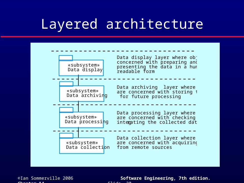
Layered architecture
«subsystem»Data collection
«subsystem»Data processing
«subsystem»Data archiving
«subsystem»Data display
Data collection layer where objectsare concerned with acquiring datafrom remote sources
Data processing layer where objectsare concerned with checking andintegrating the collected data
Data archiving layer where objectsare concerned with storing the data for future processing
Data display layer where objects areconcerned with preparing andpresenting the data in a human-readable form
©Ian Sommerville 2006 Software Engineering, 7th edition. Chapter 14 Slide 21
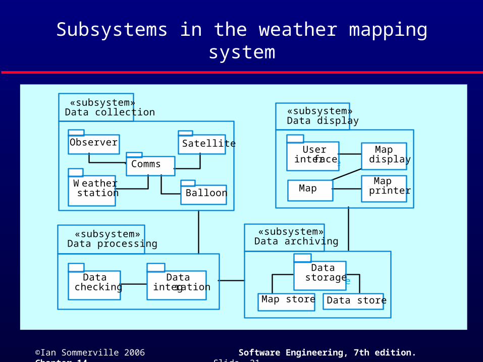
Subsystems in the weather mapping system
Datastorage
Userinterface
«subsystem»Data collection
«subsystem»Data processing
«subsystem»Data archiving
«subsystem»Data display
Weatherstation
Satellite
Comms
Balloon
Observer
Map store Data store
Datastorage
Map
Userinterface
Mapdisplay
Mapprinter
Datachecking
Dataintegration
©Ian Sommerville 2006 Software Engineering, 7th edition. Chapter 14 Slide 22
Object identification
Identifying objects (or object classes) is the most difficult part of object oriented design.
There is no 'magic formula' for object identification. It relies on the skill, experience
and domain knowledge of system designers. Object identification is an iterative process.
You are unlikely to get it right first time.

©Ian Sommerville 2006 Software Engineering, 7th edition. Chapter 14 Slide 23
Approaches to identification
Use a grammatical approach based on a natural language description of the system (used in Hood OOD method).
Base the identification on tangible things in the application domain.
Use a behavioural approach and identify objects based on what participates in what behaviour.
Use a scenario-based analysis. The objects, attributes and methods in each scenario are identified.
©Ian Sommerville 2006 Software Engineering, 7th edition. Chapter 14 Slide 24
Weather station description
A weather station is a package of software controlled instruments which collects data, performs some data processing and transmits this data for further processing. The instruments include air and ground thermometers, an anemometer, a wind vane, a barometer and a rain gauge. Data is collected periodically.
When a command is issued to transmit the weather data, the weather station processes and summarises the collected data. The summarised data is transmitted to the mapping computer when a request is received.
©Ian Sommerville 2006 Software Engineering, 7th edition. Chapter 14 Slide 25
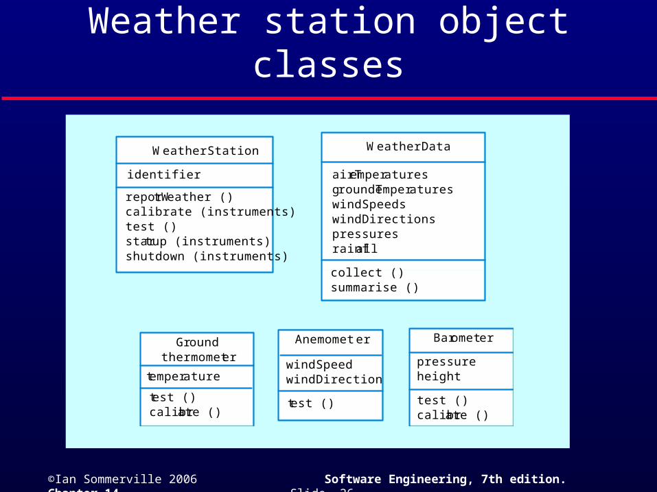
Weather station object classes
Ground thermometer, Anemometer, Barometer• Application domain objects that are ‘hardware’ objects
related to the instruments in the system. Weather station
• The basic interface of the weather station to its environment. It therefore reflects the interactions identified in the use-case model.
Weather data• Encapsulates the summarised data from the instruments.
©Ian Sommerville 2006 Software Engineering, 7th edition. Chapter 14 Slide 26
Weather station object classes
identifier
reportWeather ()calibrate (instruments)test ()startup (instruments)shutdown (instruments)
WeatherStation
test ()calibrate ()
Groundthermometer
temperature
Anemometer
windSpeedwindDirection
test ()
Barometer
pressureheight
test ()calibrate ()
WeatherData
airTemperaturesgroundTemperatureswindSpeedswindDirectionspressuresrainfall
collect ()summarise ()
©Ian Sommerville 2006 Software Engineering, 7th edition. Chapter 14 Slide 27
Design models
Design models show the objects and object classes and relationships between these entities.
Static models describe the static structure of the system in terms of object classes and relationships.
Dynamic models describe the dynamic interactions between objects.

©Ian Sommerville 2006 Software Engineering, 7th edition. Chapter 14 Slide 28
Subsystem models
Shows how the design is organised into logically related groups of objects.
In the UML, these are shown using packages - an encapsulation construct. This is a logical model. The actual organisation of objects in the system may be different.
©Ian Sommerville 2006 Software Engineering, 7th edition. Chapter 14 Slide 29
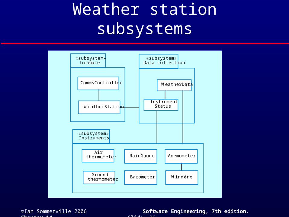
Weather station subsystems
«subsystem»Interface
«subsystem»Data collection
CommsController
WeatherStation
WeatherData
InstrumentStatus
«subsystem»Instruments
Air thermometer
Ground thermometer
RainGauge
Barometer
Anemometer
WindVane

©Ian Sommerville 2006 Software Engineering, 7th edition. Chapter 14 Slide 30
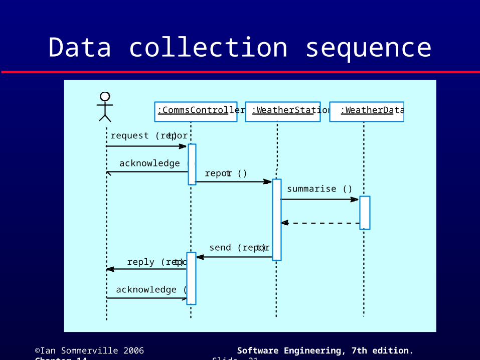
Sequence models
Sequence models show the sequence of object interactions that take place• Objects are arranged horizontally across the top;• Time is represented vertically so models are
read top to bottom;• Interactions are represented by labelled arrows,
Different styles of arrow represent different types of interaction;
• A thin rectangle in an object lifeline represents the time when the object is the controlling object in the system.
©Ian Sommerville 2006 Software Engineering, 7th edition. Chapter 14 Slide 31
Data collection sequence
:CommsController
request (report)
acknowledge ()report ()
summarise ()
reply (report)
acknowledge ()
send (report)
:WeatherStation :WeatherData
©Ian Sommerville 2006 Software Engineering, 7th edition. Chapter 14 Slide 32
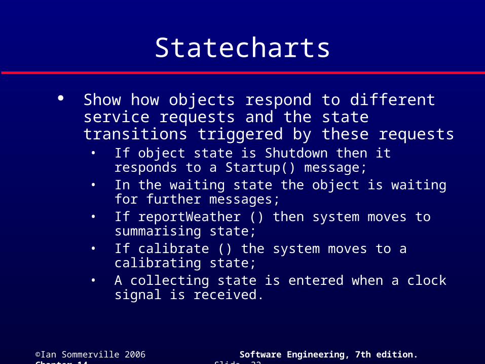
Statecharts
Show how objects respond to different service requests and the state transitions triggered by these requests• If object state is Shutdown then it responds to a Startup()
message;• In the waiting state the object is waiting for further
messages;• If reportWeather () then system moves to summarising
state;• If calibrate () the system moves to a calibrating state;• A collecting state is entered when a clock signal is
received.
©Ian Sommerville 2006 Software Engineering, 7th edition. Chapter 14 Slide 33
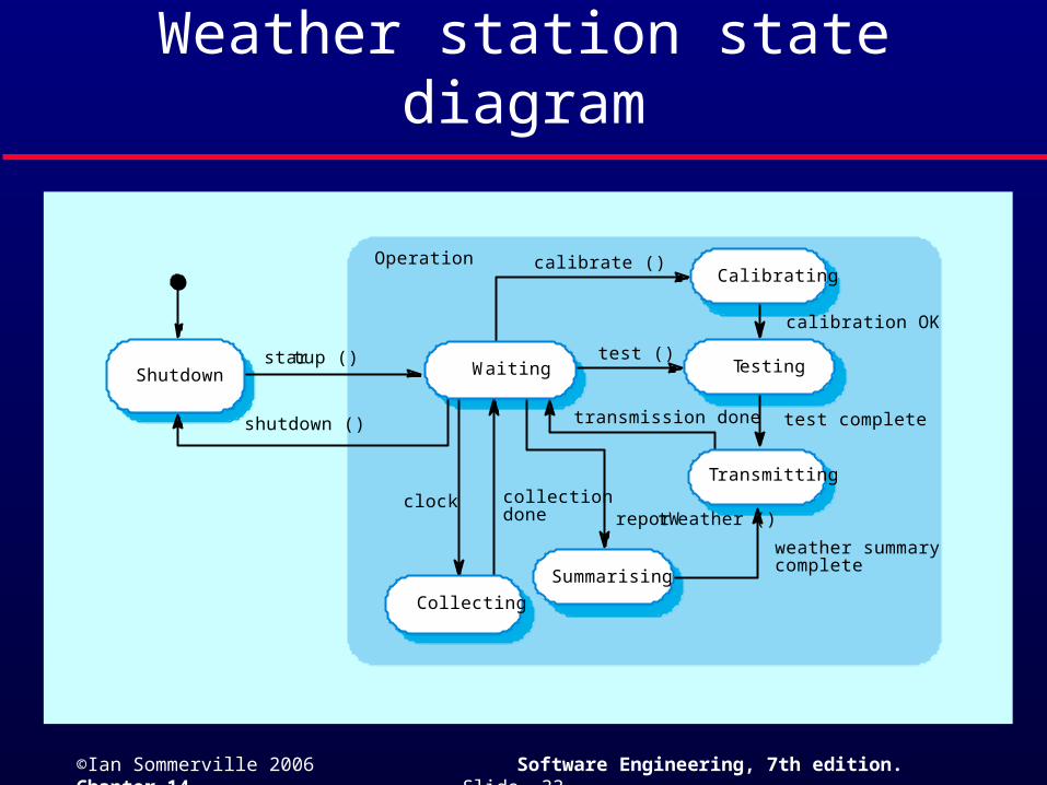
Weather station state diagram
transmission done
calibrate ()
test ()startup ()
shutdown ()
calibration OK
test complete
weather summarycomplete
clock collectiondone
Operation
reportWeather ()
Shutdown Waiting Testing
Transmitting
Collecting
Summarising
Calibrating