Embed Size (px)
Citation preview
-c" 14- P / o ) 6 13-q-d-A---; mmorwrwm,
/1) 7) S r/-
RELEASE NO: 70-50K
• 11•16,.
NATIONAL AERONAUTICS AND SPACE ADMINISTRATION
WASHINGTON,D.C. 20546
FOR RELEASE: THURSDAY A.M. April 2, 1970
NEWS TELS. WO 2-4155 WO 3-6925
P R E S S
K I
PROJECT: APOLLO 13 Env y, ei:Na
640.14000
contents GENERAL RELEASE 1-9 APOLL 10-12
Li ns 12 Ma ities 13 Ap ofile 14
LAUNCLaLaApEaTrTrSaTrLuDeLuCSPoLuAsAsTrTrRe
APOLLAp
APOLLLuChLuLuPaSo
i3OPY OCT 20 IWO
k-,f0544404
O 13 COUNTDOWN ghtning Precautioy Launch Opportunollo 13 Flight Pr
H, MISSION TRAJECTORY AND MANEUVER DESCRIPTION 15 unch 15-16 unch Events 17 ollo 13 Mission Events 18-23 rth Parking Orbit (EPO) 24 anslunar Injection (TLI) 2 14 ansposition, Docking, and Ejection (TD&E) 24 turn Third Stage Lunar Impact 24-26 anslunar Coast 26-27 nar Orbit Insertion (LOI) 27 scent Orbit Insertion (DOI) 27 nar Module Separation 27 M Circularization 27-28 wer Descent Initiation (PDI), Lunar Landing 29 nar Surface Exploration 29-37 cent, Lunar Orbit Rendezvous 37-41 cent Stage Deorbit 42 ansearth Injection (TEI) 42 ansearth Coast 42-43 covery Operations 44-45 O 13 ONBOARD TELEVISION 46 ollo 13 TV Schedule 47 O 13 SCIENCE 48 nar Orbital Photography 48-49 arged Particle Lunar Environment Experiment (CPLEE) 49-51 nar Atmosphere Detector (LAD) 51-53 nar Heat Flow Experiment (HFE) 54-58 ssive Seismic Experiment (PSE) 58-60 lar Wind Composition 60-61
APOLLO 13 SCIENCE (Cont'd.) Dust Detector 62 Field Geology Investigations 63-65 SNAP-27 65--67
PHOTOGRAPHIC EQUIPMENT 68-69 LUNAR DESCRIPTION 70
Physical Facts 70 Landing Site 71-72
APOLLO 13 FLAGS, LUNAR MODULE PLAQUE 73 SATURN V LAUNCH VEHICLE 74
First Stage 74 Second Stage 74 Third Stage 74-75 Instrument Unit 76 Propulsion 76--77
COMMAND AND SERVICE MODULE STRUCTURE, SYSTEMS 78 Launch Escape System (LES) 78 Command Module (CM) Structure 78 Service Module (SM) Structure 78-80 Spacecraft-LM Adapter (SLA) Structure 81 CSM Systems 81-83
LUNAR MODULE STRUCTURES, WEIGHT 84 Ascent Stage 84-85 Descent Stage 86 Lunar Module Systems 86-89
AULLO 13 CREW AND CREW EQUIPMENT 90 Life Support Equipment-Space Suits 90-94 Apollo Lunar Hand Tools 95-98 Apollo 13 Crew Menu 99-100 Personal Hygiene 101 Medical Kit 101 Survival Gear 102 Biomedical Inflight Monitoring 102-103 Training 104-105 Crew Biographies 106-112
LAUNCH COMPLEX 39 113-115 MISSION CONTROL CENTER 116-118 MANNED SPACE FLIGHT NETWORK 119-124
Network Computers 124-125 Apollo Ship Vanguard 125 Apollo Range Instrumentation Aircraft (ARIA) 125
CONTAMINATION CONTROL PROGRAM 126-127 LUNAR RECEIVING LABORATORY (LRL) 128-130 LUNAR RECEIVING LABORATORY TENTATIVE SCHEDULE 131-132 SCHEDULE FOR TRANSPORT OF SAMPLES, SPACECRAFT AND CREW 133 APOLLO PROGRAM MANAGEMENT 134
Apollo/Saturn Officials 135-137 Major Apollo/Saturn V Contractors 138-139
0
NEWS NATIONAL AERONAUTICS AND SPACE ADMINISTRATION (202) 962-11155
WASHINGTON,D.C. 20546 Innis: (202) 963-6925
FOR RELEASE: THURSDAY A.M. April 2, 1970
RELEASE NO: 70-50
APOLLO 13 THIRD LUNAR LANDING MISSION
Apollo 13, the third U.S. manned lunar landing mission,
will be launched April 11 from Kennedy Space Center, Fla., to
explore a hilly upland region of the Moon and bring back rocks
perhaps five billion years old.
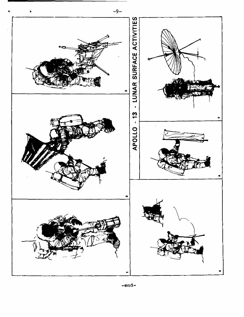
The Apollo 13 lunar module will stay on the Moon more
than 33 hours and the landing crew will leave the spacecraft
twice to emplace scientific experiments on the lunar surface
and to continue geological investigations. The Apollo 13
landing site is in the Fra Mauro uplands; the two National
Aeronautics and Space Administration previous landings were in
mare or "sea" areas, Apollo 11 in the Sea of Tranquility and
Apollo 12 in the Ocean of Storms.
Apollo 13 crewmen are commander James A. Lovell, Jr.;
command module pilot Thomas K. Mattingly III, and lunar module
pilot Fred W. Haise, Jr. Lovell is a U.S. Navy captain,
Mattingly a Navy lieutenant commander, and Haise a civilian.
-more- 3/26/70

Launch vehicle is a Saturn V.
Apollo 13 objectives are:
• Perform selenological inspection, survey and
sampling of materials in a preselected region of the
Fra Mauro formation.
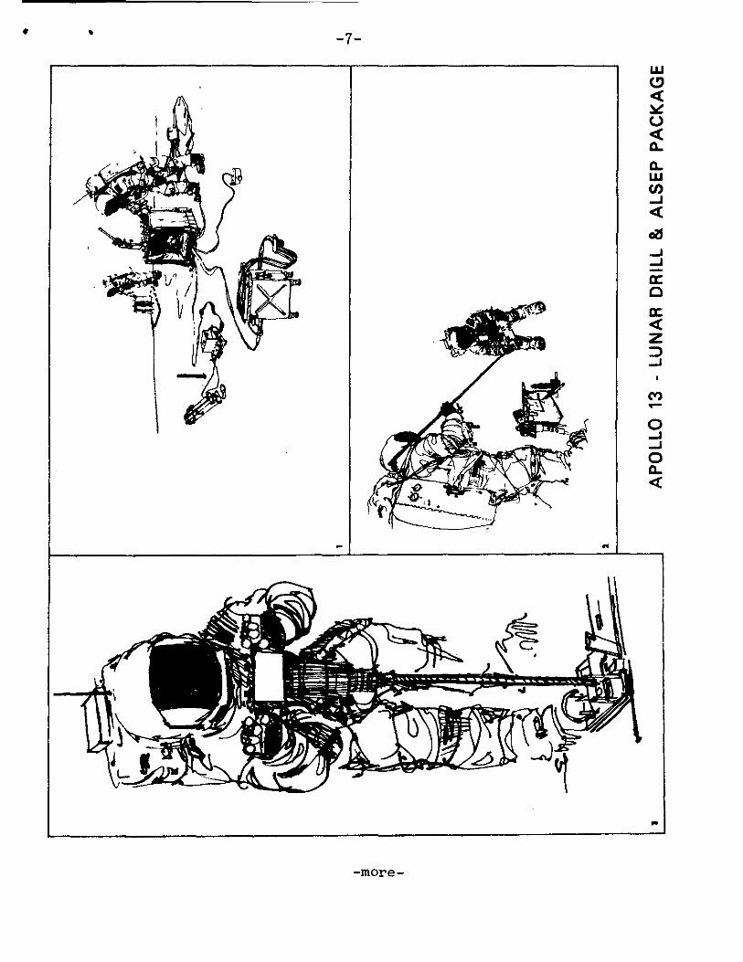
• Deploy and activate an Apollo Lunar Surface
Experiment Package (ALSEP).
• Develop man's capability to work in the lunar
environment.
• Obtain photographs of candidate exploration sites.
Currently 11 television transmissions in color are
scheduled: one in Earth orbit an hour and a half after
launch, three on the outward voyage to the Moon; one of the
landing site from about nine miles up; two from the lunar
surface while the astronauts work outside the spacecraft ;
one at the command service module/lunar module docking operation;
one of the Moon from lunar orbit; and two on the return trip.
The Apollo 13 landing site is in the hilly uplands to
the north of the crater Fra Mauro. Lunar coordinates for the
landing site are 3.6 degrees south latitude by 17.5 degrees
west longitude, about 95.6 nautical miles east of the Apollo
12 landing point at Surveyor III crater.
-3-
Experiments emplaced at the Fra Mauro site as part of
the ALSEP III will gather and relay long-term scientific
data to Earth for at least a year on the Moon's physical and
environmental properties. Five experiments are contained in
the ALSEP: a lunar passive seismometer will measure and relay
meteoroid impacts and moonquakes; a heat flow experiment will
measure the heat flux from the lunar interior to the surface
and conductivity of the surface materials to a depth of about
10 feet; a charged particle lunar environment experiment will
measure protons and electrons to determine the effect of the
solar wind on the lunar environment; a cold cathode gauge
experiment will measure density and temperature variations in
the lunar atmosphere; and a dust detector experiment.
The empty third stage of the Saturn V launch vehicle
will be targeted to strike the Moon before the lunar landing
and its impact will be recorded by the seismometer left by
the Apollo 12 astronauts last November. The spent lunar module
ascent stage, as in Apollo 12, will be directed to impact the
Moon after rendezvous and final LM separation to provide a
signal to both seismometers.
_more-
at
-4—
Candidate future Apollo landing sites -- Censorinus,
Davy Rifle, and Descartes -- will be photographed with a
large-format lunar topographic camera carried for the first
time on Apollo 13. The lunar topographic camera will make high-
resolution 4.5 inch square black-and-white photos in overlapping
sequence for mosaics or in single frames. The camera mounts in
the command module crew access hatch window when in use. After
lunar orbit rendezvous with the lunar module and LM jettison
the command module will make a plane-change maneuver to drive
the orbital track over Descartes and Davy Rifle for topographic
photography.
The Apollo 13 flight profile in general follows those
flown by Apollos 11 and 12 with one major exception: lunar orbit
insertion burn no. 2 has been combined with descent orbit
insertion and the docked spacecraft will be placed into a 7x57
nautical mile lunar orbit by use of the service propulsion
system. Lunar module descent propellant is conserved by
combining these maneuvers to provide 15 seconds of additional
hover time during the landing.
Lunar surface touchdown is scheduled to take place at
9:55 p.m. EST April 15, and two periods of extravehicular
activity are planned at 2:13 a.m. EST April 16 and 9:58 p.m.
EST April 16. The LM ascent stage will lift off at 7:22 a.m.
April 17 to rejoin the orbiting command module after more than
33 hours on the lunar surface.
--more-

,5-
Apollo 13 will leave lunar orbit at 1:42 p.m. EST April
18 for return to Earth. Splashdown in the mid-Pacific just
south of the Equator will be at 3:17 p.m. EST April 21.
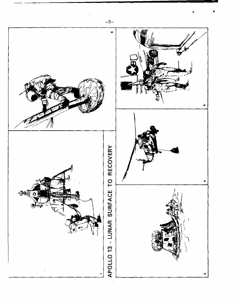
After the spacecraft has landed, the crew will put on
clean coveralls and filter masks passed in to them through
the hatch by a swimmer, and then transfer by helicopter to a
Mobile Quarantine Facility (MQF) on the USS Iwo Jima. The
MQF and crew will be offloaded in Hawaii and placed aboard a
C-141 aircraft for the flight back to the Lunar Receiving
Laboratory at the Manned Spacecraft Center in Houston. The
crew will remain in quarantine up to 21 days from completion
of the second EVA.
The crew of Apollo 13 selected the call signs Odyssey for
the command/service module and Aquarius for the lunar module.
When all three crewmen are aboard the command module, the call
sign will be "Apollo 13." As in the two previous lunar landing
missions, an American flag will be emplaced on the lunar surface.
A plaque bearing the date of the Apollo 13 landing and the crew
signatures is attached to the LM.
Apollo 13 backup crewmen are USN commander John W. Young,
commander; civilian John L. Swigert, Jr., command module pilot;
and USAF Major Charles M. Duke, Jr., lunar module pilot.
•
-more-

-7-
-more-
-8-
0..
LU
NA
R S
UR
FAC
E A
CT
c• • -9-
.•
-end-
-10 -
APOLLO 13 COUNTDOWN
Precount activities for the Apollo 13 launch begin about T- 14 days, when the space vehicle will be prepared for the start of the Official countdown. During precount, final space vehicle ordnance installation and electrical connections will be accomplished. Spacecraft gaseous oxygen and gaseous helium systems will be serviced, spacecraft batteries will be installed, and LM and CSM mechanical buildup will be completed. The CSM fuel cells will be activated and CSM cryogenics (liquid oxygen - liquid hydrogen) will be loaded and pressurized.
The countdown for Apollo 13 will begin at T-28 hours and will continue to T-9 hours, at which time a built-in hold is planned prior to the start of launch vehicle propellant loading.
Following are some of the major operations in the final count:
T-28 hours Official countdown starts LM stowage and cabin closeout (T-31:30 to T-18:00)
T-27 hours, 30 minutes Install and connect LV flight batteries (to T-23 hours)
T-22 hours, 30 minutes Topoff of LM super critical helium (to T-20 hours, 30 minutes)
T-19 hours, 30 minutes LM SHe thermal shield installation (to T-15 hours, 30 minutes) CSM crew stowage (T-19 to T-12 hours, 30 minutes)
T-16 hours LV range safety checks (to T-15 hours)
T-15 hours Installation of ALSEP FCA to T-14 hours, 145 minutes)
T-11 hours, 30 minutes Connect LV safe and arm devices (to 10 hours, 45 minutes) CSM pre-ingress operations (to T-8 hours 45 minutes)
T-10 hours, 15 minutes Start MSS move to parksite
-more-
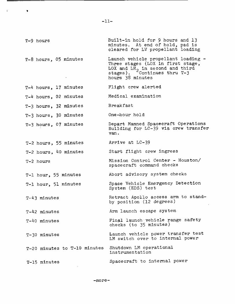
T-9 hours
T-8 hours, 05 minutes
T-4 hours, 17 minutes
T-4 hours, 02 minutes
T-3 hours, 32 minutes
T-3 hours, 30 minutes
T-3 hours, 07 minutes
T-2 hours, 55 minutes
T-2 hours, 40 minutes
T-2 hours
T-30 minutes
Built-in hold for 9 hours and 13 minutes. At end of hold, pad is cleared for LV propellant loading
Launch vehicle propellant loading -Three stages (LOX in first stage, LOX and LH 2 in second and third stages). Continues thru T-3 hours 38 minutes
Flight crew alerted
Medical examination
Breakfast
One-hour hold
Depart Manned Spacecraft Operations Building for LC-39 via crew transfer van.
Arrive at LC-39
Start flight crew ingress
Mission Control Center - Houston/ spacecraft command checks
Abort advisory system checks
Space Vehicle Emergency Detection System (EDS) test
Retract Apollo access arm to stand-by position (12 degrees)
Arm launch escape system
Final launch vehicle range safety checks (to 35 minutes)
Launch vehicle power transfer test LM switch over to internal power
T-1 hour, 55 minutes
T-1 hour, 51 minutes
T-43 minutes
T-42 minutes
T-40 minutes
T-20 minutes to T-10 minutes Shutdown LM operational instrumentation
T-15 minutes
Spacecraft to internal power
-more-
•
-12-
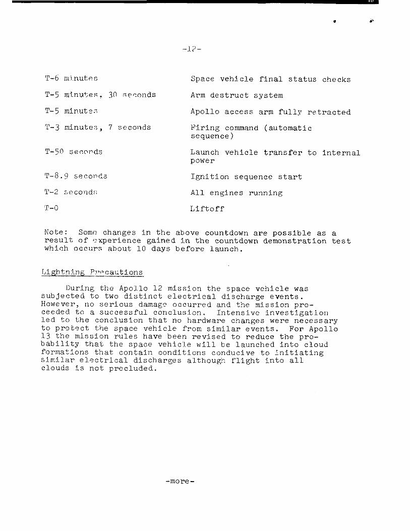
T-6 minutes
T-5 minutes, 30 •eo.onds
T-5 minutes
T-3 minutes, 7 seconds
T-50 seconds
Space vehicle final status checks
Arm destruct system
Apollo access arm fully retracted
Firing command (automatic sequence)
Launch vehicle transfer to internal power
T-8.9 seconds Ignition sequence start
T-2 seconds; All engines running
T-0 Liftoff
Note: Some changes in the above countdown are possible as a result of experience gained in the countdown demonstration test which occurs about 10 days before launch.
Lightning Precautions
During the Apollo 12 mission the space vehicle was subjected to two distinct electrical discharge events. However, no serious damage occurred and the mission pro-ceeded to a successful conclusion. Intensive investigation led to the conclusion that no hardware changes were necessary to protect the space vehicle from similar events. For Apollo 13 the mission rules have been revised to reduce the pro-bability that the space vehicle will be launched into cloud formations that contain conditions conducive to initiating similar electrical discharges although flight into all clouds is not precluded.
May Launch Opportunities
The three opportunities established for May -- in case the launch is postponed from April 11 -- provide, in effect, the flexibility of a choice of two launch attempts. The optimum May launch window occurs on May 10. The three day window permits a choice of attempting a launch 24 hours earlier than the optimum window and if necessary a further choice of a 24 hour or 48 hour recycle. It also permits a choice of making the first launch attempt on the optimum day with a 24-hour recycle capability. The May 9 window (T-24 hrs) requires an additional 24 hours in lunar orbit before initiating powered descent to arrive at the landing site at the same time and hence have the same Sun angle for landing as on May 10. Should the May 9 window launch attempt be scrubbed, a decision will be made at that time, based on the reason for the scrub, status of spacecraft cryogenics and weather predictions, whether to recycle for May 10 (T-0 hrs) or May 11 (T+24 hrs). If launched on May 11, the flight plan will be similar for the May 10 mission but the Sun elevation angle at lunar landing will be 18.5 ° instead of 7.8°.

4
-14-
z te)
z 0 5 _ s
>
0
Z a 0
H 0 4 Z •-• 1". Liu Z 1-- ,,r
. t.„,42 Z --4 d > ce- I. ‘17
.•
8 0 cm )- 0
I— in Z 5 o4 0 U
Fl > a — ,
▪
. LLt 0
r-- > co Lu
ck CA u.i 7 3
,„ w .,- L4.1 i'"'
I-' 4 ' U 8 :4 u a ,,, ,_ z z, U - z c,
iJ) 0 uo 0 t. 42e4-
— in v) < i=
E-t,
—, x
)-- ..-1 >- vl c4
4 1. I
u-k 4.
o 04
1--' .-..!
At Z = c4 --,
Z kil 1 ° Z 1---
.. a Lu n E 0 v, . ...., U z W a.- an c5_, ....-
> o -z /7 oe eR
CM
SP
LAS
HD
OW
N
AP
OLL
O 1
3 F
LIG
HT
PRO
FILE
-more-

-15-
LAUNCH, MISSION TRAJECTORY AND MANEUVER DESCRIPTION
The information presented here is based on an on-time April 11 launch and is subject to change before or during the mission to meet changing conditions.
Launch
A Saturn V launch vehicle will lift the Apollo 13 space-craft from Launch Complex 39A, NASA-Kennedy Space Center, Fla. The azimuth may vary from 72 to 96 degrees, depending on the time of launch. The azimuth changes with launch time to permit a fuel-optimum injection from Earth parking orbit to a free-return circumlunar trajectory.
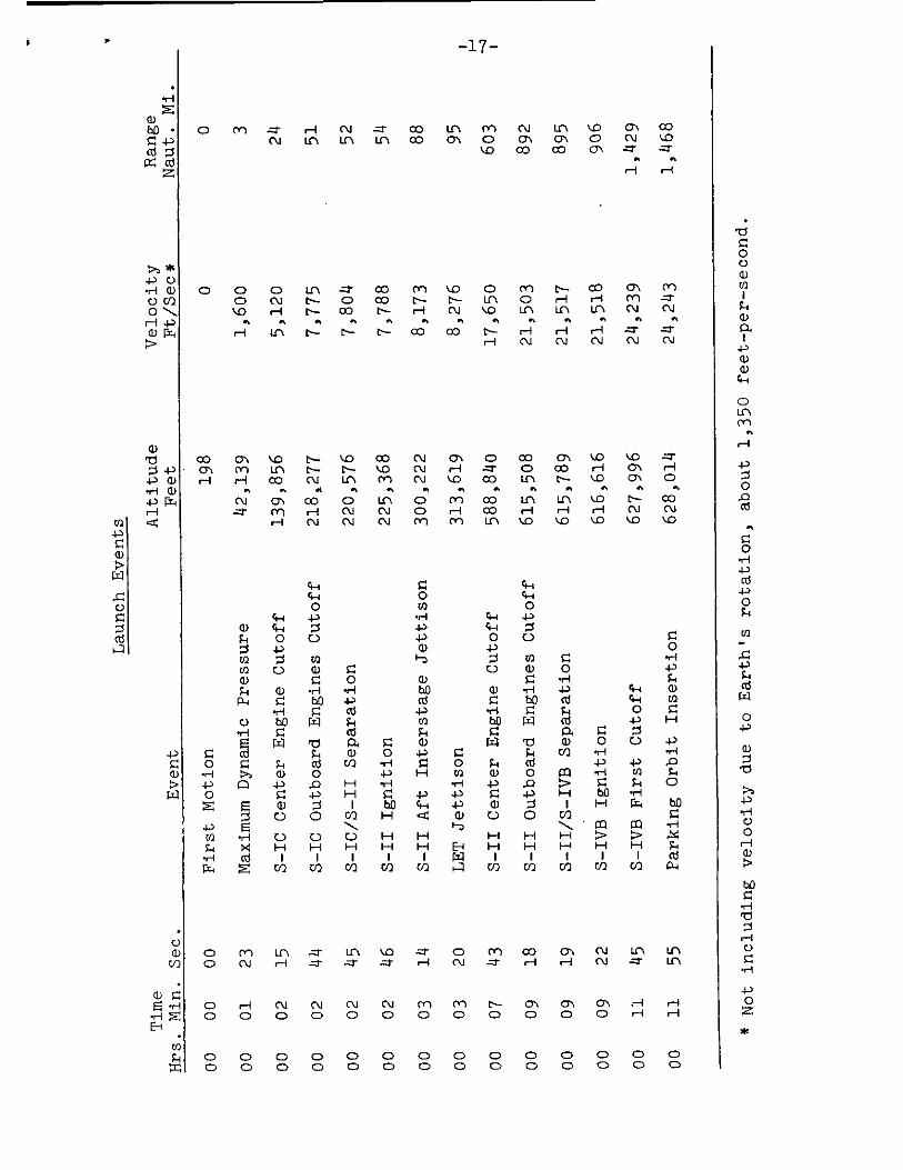
April 11 launch plans call for liftoff at 2:13 p.m. EST on an azimuth of 72 degrees. The vehicle will reach an altitude of 36 nautical miles before first stage cutoff 51 nm downrange. During the 2 minutes 44 seconds of powered flight, the first stage will increase vehicle velocity to 7,775 feet per second# First stage thrust will reach a maximum of 8,995,108 pounds before center engine cutoff. After engine shutdown and separation from the second stage, the booster will fall into the Atlantic Ocean about 364 nm downrange from the launch site (30 degrees North latitude and 74 degrees West longitude) about 9 minutes 4 seconds after liftoff.
The second stage (S-II) will carry the space vehicle to an altitude of 102 nm and a distance of 892 nm downrange. At engine shutdown, the vehicle will be moving at a velocity of 21,508 fps. The four outer J-2 engines will burn 6 minutes 32 seconds during the powered phase, but the center engine will be cut off 4 minutes 47 seconds after S-II ignition.
At outboard engine cutoff, the S-II will separate and, following a ballistic trajectory, plunge into the Atlantic about 2,450 nm downrange from the Kennedy Space Center (31 degrees North latitude and 33.4 degrees West longitude) some 20 minutes 41 seconds after liftoff.
The single engine of the Saturn V third stage (S-IVB) will ignite about 3 seconds after the S-II stage separates. The engine will fire for 143 seconds to insert the space vehicle into a circular Earth parking orbit of 103 nm begin-ing about 1,468 nm downrange. Velocity at Earth orbital insertion will be 24,243 fps at 11 minutes 55 second ground elapsed time (GET). Inclination will be 33 degrees to the equator.
*NOTE: Multiply nautical miles by 1.1508 to obtain statute miles; multiply feet per second by 0.6818 to obtain statute miles per hour.
-more-

-16-
The crew will have a backup to launch vehicle guidance during powered flight. If the Saturn instrument unit inertial platform fails, the crew can switch guidance to the command module systems for first-stage powered flight automatic control. Second and third stage backup guidance is through manual takeover in which spacecraft commander hand controller inputs are fed through the command module computer to the Saturn instrument unit.
LET
Jetti
son
S-II Ce
nte
r En
gine
Cuto
ff
S-II Aft Inte
rsta
ge
Jettison
S-IC/S-II Se
para
tio
n
S-II Ignit
ion
Firs
t Mo
tio
n
S-IC Ce
nte
r En
gine
Cuto
ff
S-IC Ou
tboa
rd En
gines Cu
toff
Maximum Dy
nam
ic Pr
essure
S-IV
B Fir
st Cuto
ff
Parking Or
bit Inser
tion
S-IVB Ig
nition
S-II/S-IVB Se
parati
on
S-II Outb
oard En
gin
es
r1 z b.0 • • 4) cd
LY cd z
* -Pc) .H a) U co 0 H 4-3
r=i
Laun
ch Ev
ents
4)
a)
U a)
Co inclu
ding
velocit
y due
to Ea
rth
's rota
tio
n, about
1,350 fe
et-per-second.
0 z
-17-
N tr,, lD ON 00 Crl ON 0 CV '.0
CO CO O\ ••■
H H
H 01/41 CO U\ CO Lrt Lf1 1.11 CO 01 0
CD 0 0 LCN CO MVO 0 CrIN-0001Cr)
0 CV C.-- 0 CO N- t.-- Lfl 0 H H CO -. -
'1/41D H N- 00 C-- H CV VO Lrt U LC-1 C1.1 CV
a n a a n, a a a n a a a a
H 1f1 C.-- N- C.-- CO CO C-- H H H .- -Z-
H CNI CV CV CU Cll
CO 01 VD N- VD CO CN ON 0 CO ON LO t..0 -••
• aN, cn in E.-- r-- '..0 CN H ..- o co H ON H
H H 00 od in Co (N %..o co LC N C--- %.0 ON 0
r, ., A a a a a a n a a .. a
CV 01 CO CD LfN CD Cvl CO In Lrl '.0 t--- CO
.,- CO H (NJ CV 0 r-1 CO H H H C 1. I CV
1-.-1 CV CNJ CV CO CO In ■D ,,CD ■-/D ■.0 ‘.0
4-4 ce--1 0
4-3
LCN H
VD ri
O C\..1
Co CO H
Cr \ (XI Lrl
0 0 0 CD 0 CD CD ID cp O H H
00000 0 ,0000 00 0 CD 0 0 CD 0 0 0 CD 0 CD C)
0 0 Ei
CO CD
CD CD
11 rq 0-PH 0 Z 03 E-1 t-i .4-1 •r-i •r-I
4-) al 0 * .P 0 4-.)
F-1 0 ;.t 4.0 Z rn X.0 a) Cri (1) F-1 0 Z t. - g-i SD, E 04-P 0 I-1 In 0
Luna
r orbit in
ser
tion
S-IV
B im
pac
t
Midcourse corre
ction 4
Midcourse cor
rection 3
I • .4 - 1 8
g-i 4-) F..4 4-) g-4 •ri 4-1 Z •H a 0 04 0 0 JD 4-) 9--1 E 4-)
f-i a) g-4
- I r-1 C/2 ;4 Fa
4) r1 .0 ;-■
Z i g-i• o a) ;-1 r1 En •H 0 0 0 0 H
tg) e) 0 Z Fa 0 4-) a • 0 cd 04 H to .4-) 0 •r-I [Id re") 0 -4-) 0 4-1 0 0 0 4-) 0 0 4-1 r0 ►-.1 •--I 01 0 0 0 .7-I g-t 0 n-I 9-1 Cd CD C.) .1-1 0 E-I e--• I.I1 .0 Cr) v-1 H x 4-I 0 A ci E 4-) H cd 0 E 0 .P 0.4 0 • r--i 4_)
Si '1-4 4-) P-1 CIS 1---1 cd a co 0 cd 4-) I 04 0 0 0 a O cd 0 cd 0 I F-4 0 E E F.4 0 c4-i 4-1 0 C..) 4-4 4-) V ;-1 0 •--I
4-) Sal -P ;-1 cd 0., -H 0 0 0 0 0 .0 IH r-i Z 4-1 C.) c/) a o g4 0 cd c.) 7-4 M In C 4-) 4-) H r-i
•r1 ..0 'r1 •H bO 0 0.) S-4 0 Si 0 a) r--i g.♦ i---1 0 a) o a)
4.) s.4 F-1 . 0 04 .P cd 'CI 0 b.° 043 0 s---* 9-4 >a F.-4 04 Z F-I z cu a) co -::a CO •,--izot.) - .es-1 ,r: E O al 0 s~ a 1 a) $-.1 to xi cd cd 0 V-4 -P 0 cv e
-r-4 W •ri cd .) r.0 lb ;-, H .0.0 10001:1)043 4) U) 4-) 4-) H E cd I RI, H .0 (1) C.) A -P 0 > Pa 0 F-4 4-) CO • S.-1 ;.4 0 CO I .-1 14 •1-1 I 4-) I) 0 co •r-I 0 0 (1) 4-4 ;-1 %.0 4-) 0 cd 0 0 M > ci) to a) Z >>1-1 ia.) co a..) •,-t -,-, I 0 ,1 .,-1
F-1 o r-i •f-j cd (Z) 041-1 0 • Z Z F-4 H cd a) 1 P-I
P.4 H 0 F-I 4-) CU 2 C/) Cr) GL4
0 • IA 0
a)
cd VI r--- H -- 0 L.C1 0 0 in
,.1.",-... (Y.) . * r-1 * * H
0 -1--1 Crt _- I ch Co i
(1) 01 .. I . 1 • a) L.r., a CV
,--1 ri, LC.1 . .-i 1
CD CV
. . • • . . . . E E E E E E E E E
. . .
E-4 a a a a 104 cd 04 04 R. p. 04 Ci)
r4 co c)-, ... (.1 .- ....- co co co 0-,
--... c., .- H H On Lcl In Cr) Cr) Ch LC1
a) •• • • •• ••
4.) c‘) L.r, ..0 ,.0 ,-1 co os. 0.1 t---- t- cd Pt
H H H H ri 0.1 CU Cr) -- .' =-
1-1 H H H H H H H H H 1-1
to to Fs Fa
H
•
H LC l VC) 0 ON. H 1(' '...0
M H t'n 0 CD H - N Ln CM .,-
P • • .. • • • • • • • •
/4 • 0 C‘i Cr) 0 I t'.• N-
O U) 0 0 0 0 0 rn IH N.- N.-. F.-I0
i-'1
Z CV 0
Z •r-i O4 U 4 0
-.:-I • -I H 4-) Z .4...) .----.
(1.1. •ri (1) 1.) .4-z F-4 Cl-t Z Cll Si (r) H Z 0
H C..) Cd S4 14 S4
Cl) Z r.7.1 to 4-)O 0 g-I ,c1 Z r--I xi •ri a) C to 0 fi-,
z H U .0 W
•
F i cd 1 rcs ›.3 T..-1 Er) •r-I M E-1 ....... U W V2 .......
oll
o 13
Missio
n Ev
ents
0 4-) cd 0.4 0 cd I H 0 0 I CO 0 0 0 A PI to 0 U3 Z a) -1--1 0 r-I ••% 0 0 4-4
0 0 E 0.4 '0 g•I ;-■ ''' 71 Ct 4-3
ose & Re
sult
ant
Seis
mic even
t.
Ea

orbit insertion
CSM c
ircu
larization
CSM-LM undocking
step
s to sur
face
camera on
and erects
0 .,
4, 4.> E 0 1 0 • „I ..4 4
•,-1 cd 0 a) 4-) H 0 -r-i • .0 'ICJ ;..4 cv -4-3 4-4 Z ;4 Ea. 0 4-> 1-1 ;-.1 0 cd '1/4.0 VI (L) cO ̂, V) c..) --., 0 .1-I 04 X Fa C.) Z •:$ a) E Fi 41) cv a) cd En a) H
C.) Ed cl. .p;-1 rod) r-I
cd 0 V);.4 0 u) Ls-, ^, 0 r-1
Z •H E • 0 a) 0 4-4 0 U] 4 ;4 4-) Z 4-i H 0 •H g 4 a) r-i 01 a) 4 Ed 0 cd -0 a) O a) Lc■ 9-1 E O 4 rt En ,--i
rc-9 E tn 03 aZ
) Z •
a) 4-3 0 F4
4
04 •
H° ct1F- ct9 .4 04 a) Z V) En 0 ;-, rd
ti-N En 0 E .4 o 4
• P.1 Z U? Sa. N cl
t--- 4 ;4 cd C) cd a)
;♦ X •.-1 4-4 U) fal i..4 Z (1) Q) r i r i VI N r-I H -4-3 • I -, 0 C.) +.'' ttO
..CI 0 4,-)n ;-1 4-) a)a)4.)4-)cd .1(14i._) o 0 Et •ri a-4 CL) •H a) N •,--t 44 cd fil -,1 -P
F.4 cn 4-) 4-3 .0 En .0 ;-4 cd .0 rti Si e ciD t-r) 0 RA Z VI g-4 -P F-1 .4 F4 r :J ;.; _:i c., .7:
Pa cr) •4 41 0 cd H 0 E1 .000 0 6 1 4- 1- 1().•
Q.) • td:l C.)
4 a) or-) LC \
CS V1 r1 Q
-P '0 CL)
• ell Pr.4
a)
ose & Result
ant
Orbit
. . . . .
E E•
o • •
04 al ‘11 cm, cd cd cd
Co Cr”)
LfN. H C I
▪
r
▪
e)
Lrt 1/4.0 01 Ol N CV CV
a:3
R.1
cd cd
ISl L-
C11
Lf1 Lc) L rt rak
0 r
▪
i H H H
r1 LIN ■.0 in r- -I ( \ I (7) 1/41) rH C.-
= --* t-i Cr) cn CD r-1 C1/41 CU (1.1 . -
E-t •• ol. • • Cn Cr)
W Z1 . I-1 Cr \ CZ) Cr) Cr) CO CO CO CO
C. U) CO a \ 0 CD ( D 0 0 0 C) CO CO
g-I H t- -1 1 1 H r--I 1-1 H (2 G
■-11 H H
›. .4 0
;-1 P•• a) cd ;4 V i30
o a) U r-:
Z H Cd 4i -P
43) ..- -... Z ci-I 4
c) 1 1 O ;4 o
tr) q 0 •.-1 '..1 C)
a) Pa 4-) GO
rd ' ' Z Cd o to --i -P
7:5 Z 0 •f- 1 Cd C)
a.) 0 r0 ;-i r • (v.
F.-. •r-i 4 • C1 ,---I
a) 4-3 C) a) (/) 14 H 0 • (15 :::3 0 (/) 0 as O -.--i 0 cd QJ -P 0 rH
•,--1 g-, fa. si c•-•. Pf. E
.':. 0 '.7_; a) •r-I c--1 Cd •H 1-1 (1) a) 4 i 0 0 10
—20— ^11
ose
& Result
ant Orbit
4) b • f) 0
g ctS rt) 4 N. O 4-)
a) • a)
r-I Pr-i a)
. .
. . . . . . . . . . . • 0 E E 0 0 E E E E E E E 0 E • •
. . . . . . . • a a H ct3 Cd cri Cd al cr3 Cd Cd ad al cr3 ia ci) H 0 ril ',ID 0 C-- cn (Y1 in N.-VD HiNi 1/4000HN •-..... LCN 1-1 H .' CV in -1- Ls- \ H H in In • • • • 4) PP •• •• a• Pa •• •• •• •• • ea •-• a a 4-) CV in In in i.n. In in in 1...o 1.0 t-- Cr.i H H Cd
I:2i '1/40 ■-0 ■.0 t,o ,1/40 '1/40 '1/40 1/40 1/40 1/40 '1/40 '1/40 '1/40 '1/40
H H H H
.1-1 in N-- •M'' 0 0 CD .=.. Cr) Co ON CO LeN CO C.--
Z .. in o in H c"ki in .' in in - . -- tr% 0
&I • • • . • • • • • • • . • • 10- •• •• •• •• •• •-• ••
rX/ • CO CO ON ON H H H H H H rol L•••- N- 00
0 L) 0 0 0 0 H H H H H H H CV C\t CV H ,--1 H H H H H H H H H H H H
0 4 4-) O Z 0 P 04 0 •X 41 4-) P 0
bi) I Z 0 g aS in Ft cd 40 4-) 0 ,0 •cl
al H 0 e z o z 4-4 z rn a) al
4-3 03 g 0 F-4 4) P. O H • 1-4 I-1 Z H H p
E g C/) ha104 4-1 g ■ c-r cd 14 0 0 • 0 a) a) P 0
-) +3 .0 b ;-1 cd al bD u) g co p (Ts ul u) P-1 •Cl ii, '3-,3 a)
4-) 'CI $-. Z >, g
o N bo E 0
cd (1) Z Z H P-i .H U)
4-) (1) Cd 4-) w A. rci bo rx1 ,o 4-1 I, U) Z el) f3:1 a) 0 CD ggri) z 0 g 4.. CV a) F-4 I g-1 (CI •::) cd -•-i 14 al a) al Z H
co 4-I .., H 1-1 04 ril 1
•
11 PA ;-1 M 14 0 14 I-1 14 • 0 Zt Z f::) la) •P ‘1 ai 0 a) 4-) cli. 14 4-.) 14 u) c...) 0 u) 0 0c) r...) al Li)
rd .4-) g g H 0 5
.i-i F4 g-i al a) H fa. 0 X CO a)
in g 0
0 4.-1 0-1 4-1 gori W ID
ni:l 0 04
111 Z o i4 0
Z i4
p..4 0
43 Z
a) P
1:1-1 Z 14
,...1
;., ,a, 4-) Z co a) 3.4
14 P 0
U) u) a) P fa4 cu s-1
-• I:3 0 U)
H 0
.. 0 4-) cd .4
E 14
U)
a) bf) g al
C)
CD
Cd H a
Co C)
CV I
-4
r.4
P 0
4-1
ID (f) a) g-1 al a) r2i
0 0 al
4-1 P 0 Cl)
4
u) o. (1)
4-) co
14 Pi (....)
4.) 0 cr3
4-1 P 0 u)
U) o. (1)
4-) U)
04 Z f4

ose & Re
sult
ant Orbi
t
Pa
-21- 1 4-)
iv (1) TS g ..- ia, • cd al
LIN t--1 ,Z C.) Z (/) - a) 0 CD Z Z
X O cr., Z H .0 0
a) ORS CY* O g-i Z 4) ID 'CS 0
;-, 4-) • • ;-1 H ,C) Cd Z
•ri 0 • H F-4 U) 34-) Cr) 4--1 $-1 0 Z •T•I 0
O CO a) 0 3 ,i:, bf) 4-) C..) 04 to y 0 ct H 4-) NI Ts 0 0 4-) .0 ..0 E cn (1) (--I
14 rci Z a) off ..---) H 1--1 .0
Ei) v) 'd a) H 4-) g-1 a) cd g-1 cd v) to cd v) ca .1-1 4-) Z O Z .1-1 A f.-t rcS En O 0 0 cd E 0 cd 0 Li"-N 121:1 H > f4 ci-I c4 •I-) H
a) • Tan c.) g 0
cd c/) .,- Q
..0 "s•-■ _.- In
CD -P C. a)
• a) ‘..0 1--1 r=4. a)
E • • • . .
04 • • • •
H 0:3 cd cd cd cd cd ctS cd cd cd
Cl) H
ftl Cr) N- CO H 00 .- t---- C1.I 01 CNI t--
...,,, r- -I H -' -- In liTh (1.1 C \ 1 (Y) H
a) CD • • ..
-P H 1---1 H H H H H t--- t---- co Cr,, 073 (::)
'0 N- N- N- t--- t--- N- t--- I"- N- N-
H H 1-1 H H H H H H H H
H co . - in co LC' H -. - cr, ..c) 01 .. -
1--I 0 0 CV 411 -- -- 0 H H Q
E-i• • - • •
W • OD H H H r-I H H N- C--- CO ON
0 Cl) Ct-I On m m m m m m m m on
F-1 ,--i 1-1 H H H H H H H H H =
En a) 1--1 r-1 C.) O a) (1) Cr) •r-1 •1-1 a) 4-) 0
cd VI v) a) 1-4 cd a) g-, 4-) -, A 4-) rcs
80 th (1) 4 ) Cl) 01 g it
Z •r-I cd cd 1- Z a) g-1 a) ;-1 4.) ›. cd r1Z; a) H 03 v) H 6.0 • A 04 .0 a) O a) A A Z cd H • E r I 0 0 rc;
1---1 .0 En ,c o a) g-1 v) cd H .,--I •.---. g-t O (1.) C_) .1-1 'PI (1) 0 0 g-I I—I 4-)
Cll 4-) r-1 Z 4-) al Q. 1-i o -p VI b.() a CD 0 >4 R. Cl) Z Z 4-) Zc.) cd
a) E 1-1 a) o Z a) .H (1) ......, 4.) ,......
rd g-i CO 4-) H J--1 CIS (1) 00 .0 H C) to = H 0 u) H taQ •ti VI 4-i 4) Cd Z Z a) (1) 0 to 0 O 1.1) to C.) Z 0 0 0 0
4-1 La C.3 C) 4.) •1-1 'CI H O 0 0 H 0 ...... 4-) c,-, -P •.--1 •ri g 4 CS (I) Cl) O H 4-) g 0 00 a.) O g cd F-1 U) to U .P • CI) cd cr) -4-) a) s~ a) cd c-I H P g-i 4-) cd a) vs 1-4 -P 0 -r-i 0 ,C > •g-1 H H ,.0 Sai 10. (3 g-1 1--1 cd a) ,-.1 i4 4-) x tIO fr-1 t∎D H 03 C_) E 4-) ,-i cd fa-, 14 P-c f4 04 to ,a •r-i -,-i
a) c) cv cd O a) o a) Z ri Z P a) Z g-1 Z Z Z a)
M 0 cd E u) U i: cil talD i- r...) i- 0 M 1--A 0 a -1-k 1-1 .0
& Resultant Or
bit
U) 0
F-1
CV 0 CY-1 ON Cr) 0 H CV .. ..
.1- Ln -- C..--
..• ,- Ln '1/40 H H H H
LM RCS
term
inal phase
separation 4->
0 a)
tit:f
a)
cd 4-3 U)
.4->
U)
ctS
PG -....„- LM
asc
ent stage
impac
t
Plan
e cha
nge for pho
tos
0
4-> C) a)
•H
4-) Er) P4
1—I
4-3
Rendezvous
(LL c-i -22 "••
4) 4-) 4%
Z I C.) in 4-1 0 I Cil g-4 (1:3 04 a) O a) a) 0 fa ci-i E H
I> (/) 4-) V pt E 0 H I a) rci QS 0 • 4-4 al H a:;) ;•1 •1-1 rn Z -f-I E Cl) H E 0 a) Z c) 4-4 rX Z
•H E
•
•ri ) t1.0 ca In I tti H bp 0 a 0 4-) cii i—i '0 ;.4
.1 Z > .P g-i C. E
4-> • LO -H ta Z 0 cti ca 4-1 0 • ctt ›. • u) -X (1) pq 4-> 4-> 0 c) 4-) in ia-t A 0 F.., o 0 cd 9:3 4.) a) Cr) rx.1 4-> 0 H g.1
•
'CI 0 g-I ;•4 0 C') ̀CS Z 4-> cd 'CS .0 a) C) C.) al (1.) .0 0) 1-1 Z • H o
;4 ;4 cd cd W c.) V c-I al r-I <0 cr3 ›-3 a) cr) cti e0 ca O ;4 ri) Z a) b0 ,C 4--z -4-> 3 Z U) g-t cd "-I 4-) 4-> Z On u) 04 r0 cd u) 0 al a) a) cn cd 1) cri ai r—i a) a; c_> r.1 • 4-> 4-3 • TS (I) 4-)E E 4.) g-i -P g-t 0 0 0 a) s~ 4-4 s I-1 0 • 0 • -p0 0 ;-1 b.0 4,) .0 4-> CO H 0 cd u) a) ;4 -P E .p 0 H al 0 c.) ,C -P .0 g.i 04 Z s~ > „C H co Z a:3 I •--1 0 4-) a) 4-)
[0.0 E 0 E cd a) 4-) 40 .0 .H (1) 5.14 0 U) 0 •i-D V-4 'I-1 0 Cn 0 0 ;-{ ;-1 v-I Z ;-1 (1.) > E -P 04 a) .. Z cd
1-1 cr) c) cd 0 ol 0 -P P4 9-4 0 ci) 0) H cd -:0 i: 104 1--i 0)
a) • 110 o
cti r.r)
() 4-) al CV
• a.)
'1/40 CO
a (Y1
. . . EE . . . E
E * E 5 E
cd cd . . 0:3 El cd a fa. a Ct) a co vz) 1-11 0■ ...- Li-1 r--- LC Cr) 0..1 .N., Lr% •• 4-1 ...- H a) cp cD •• •• •• 0.1 4-) 01 H H H cv Cr) H al A
CO
q
E-1 C/)
a) • 4-)
Cd
(t$
Midc
ours
e corr
ection 5
—23-
I 1:5 F-1 a) 1 0 0 4-) (i) rd I Li'l O >z c-I a) u) i •
P+ P-I 4) ri) 0 =I C-- 12) E -IE • Lc\ 1.11 U)0 Z Z g-i a) a) 4-) CO 0 • H gi 0 a) cd a) -LH 4-) cd saL rd L-I
.0 g-L Z 4-i O a)PA H 4-) 0
a) ',III o, fl .,"? iz, .. o 0 cd rd cl--L g-L a) a) a) ,0 CV 4-3 a) a) •--1 H 4 H 1-1 rk 1-1 o Z '0 'd • H a) Z u) . in a)
,--t 0 se rd 7:5 ■.0 CV 4-3 4-3 ' ,.0 3 ri 0 (1) • 0 • 0 (1) 0,1 ., E or-I ri
g-i U) g-I Cd 0 i`, 4-) g-i 03 Z bi)
a) n3 Z H o Z rd -P 9.3 co n3 by 4i f-i 0 cn a) 0 W •tz3 0:5' s~ iw - Z H o En •1-1 a) •,--r g-I 1:/ 0 a) Cd (I) 1-1 41)
• g_i cd 0 g-L 0 F-1 t ',14) 2 '2 4- ti) Z 4-) g-+ g4 (I) •H
• g-1 (1) Z 0 0 00 o cd.E 03 n3 0 a) P-, E-i g-L -LH c.) o cd ci 41 C.) LT-1 g:34 1--1 r-i CO
Result
ant Or
bit
0 0 I 1
• E . . 1. •
• 0-. •
Qi rat P. al Cr-)
Cr) C) t--- (-Li t----
LC H CV Cr) cr.)
0 H H 1---1 g-1
Ck.) CV CV 04 (NJ
EI -22
hrs
U) S-1
Cr) LC\ Cr) • •
CD C t--I
H CV CV CV
VD N- O
O
O 0 ri
4-)
C.> ■—••
(1) (1) 0 a) • r. g-1 g-1 n3 O 0 cd
g-L 03 a)
a) a) a. 4-3
(t) (1) Fr Ci) •H
O
•
0 C.) 0 C') 4-3 '0 • :3 4-3 9) •H •T 5"
c11 Spla
shdown
-24-
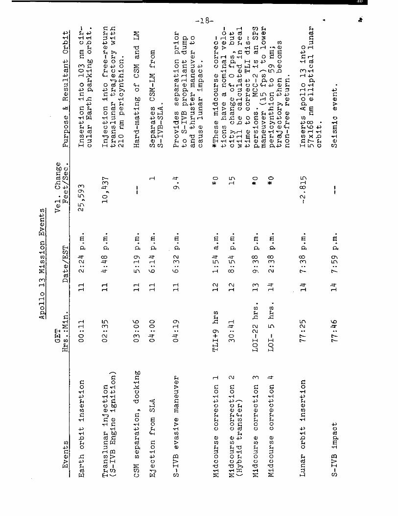
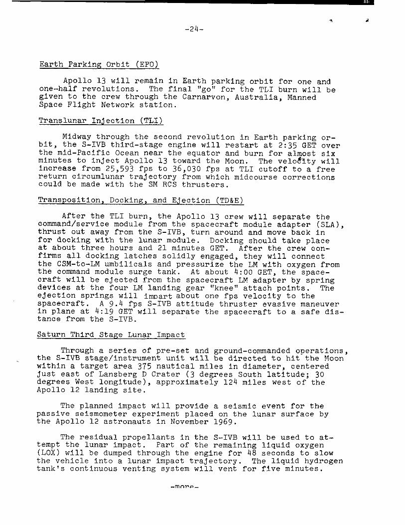
Earth Parking Orbit (EPO)
Apollo 13 will remain in Earth parking orbit for one and one-half revolutions. The final "go" for the TLI burn will be given to the crew through the Carnarvon, Australia, Manned Space Flight Network station.
Translunar Injection (TLI)
Midway through the second revolution in Earth parking or-bit, the S-IVB third-stage engine will restart at 2:35 GET over the mid-Pacific Ocean near the equator and burn for almost six minutes to inject Apollo 13 toward the Moon. The velotity will increase from 25,593 fps to 36,030 fps at TLI cutoff to a free return circumlunar trajectory from which midcourse corrections could be made with the SM RCS thrusters.
Transposition, Docking, and Ejection (TD&E)
After the TLI burn, the Apollo 13 crew will separate the command/service module from the spacecraft module adapter (SLA), thrust out away from the S-IVB, turn around and move back in for docking with the lunar module. Docking should take place at about three hours and 21 minutes GET. After the crew con-firms all docking latches solidly engaged, they will connect the CSM-to-LM umbilicals and pressurize the LM with oxygen from the command module surge tank. At about 4:00 GET, the space-craft will be ejected from the spacecraft LM adapter by spring devices at the four LM landing gear "knee" attach points. The ejection springs will impart about one fps velocity to the spacecraft. A 9.4 fps S-IVB attitude thruster evasive maneuver in plane at 4:19 GET will separate the spacecraft to a safe dis-tance from the S-IVB.
Saturn Third Stage Lunar Impact
Through a series of pre-set and ground-commanded operations, the S-IVB stage/instrument unit will be directed to hit the Moon within a target area 375 nautical miles in diameter, centered just east of Lansberg D Crater (3 degrees South latitude; 30 degrees West longitude), approximately 124 miles west of the Apollo 12 landing site.
The planned impact will provide a seismic event for the passive seismometer experiment placed on the lunar surface by the Apollo 12 astronauts in November 1969.
The residual propellants in the S-IVB will be used to at-tempt the lunar impact. Part of the remaining liquid oxygen (LOX) will be dumped through the engine for 48 seconds to slow the vehicle into a lunar impact trajectory. The liquid hydrogen tank's continuous venting system will vent for five minutes.
-mnrp-

'
1
• • "0-
o41111,1 .
0
uJ
CC
S-IV
B L
UN
AR
IM
PA
CT
-26-
A mid-course correction will be made with the stage's auxiliary propulsion system (APS) ullage motors. A second APS burn will be used if necessary, at about 9 hours GET, to further adjust the impact point. Burn time and attitude will be determined from onboard systems and tracking data provided to ground controllers by the Manned Space Flight Network.
The LOX dump by itself would provide a lunar impact; the mid-course correction burns will place the S-IVB/IU within the desired target area for impact about 20 minutes after the com- mand/service module enters lunar orbit.
The schedule of events concerning the lunar impact is:
Time Hrs:Min Event
02 42 Translunar injection (TLI) --maneuver completion
04 19 Begin S-IVB evasive maneuver (APS engines)
04 21 End evasive maneuver
04 36 LH2 tank continuous vent on
04 41 Begin LOX dump
04 41 LH2 tank continuous vent off
04 42 End LOX dump
06 00 Begin first APS burn
08 59 Begin final APS burn (if required)
09 04 APS ullage engines off
77 46 Lunar impact of S-IVB/IU
Translunar Coast
Up to four midcourse correction burns are planned during the spacecraft's translunar coast, depending upon the accuracy of the trajectory resulting from the TLI maneuver. If required, the midcourse correction burns are planned at TLI-1-9 hours, TLI+ 30 hours, 41 minutes, lunar orbit insertion (L0I)-22 hours and L01-5 hours. The MCC-2 is a 15 fps SPS hybrid transfer maneuver which lowers pericynthion from 210 nm to 59 nm and places Apollo 13 on a non-free-return trajectory.
-more-
-2 7-
Return to the free-return trajectory is always within the capability of the spacecraft service propulsion or des-cent propulsion systems.
During coast periods between midcourse corrections, the spacecraft will be in the passive thermal control (PTC) or "barbecue" mode in which the spacecraft will rotate slowly about its roll axis to stabilize spacecraft thermal response to the continuous solar exposure.
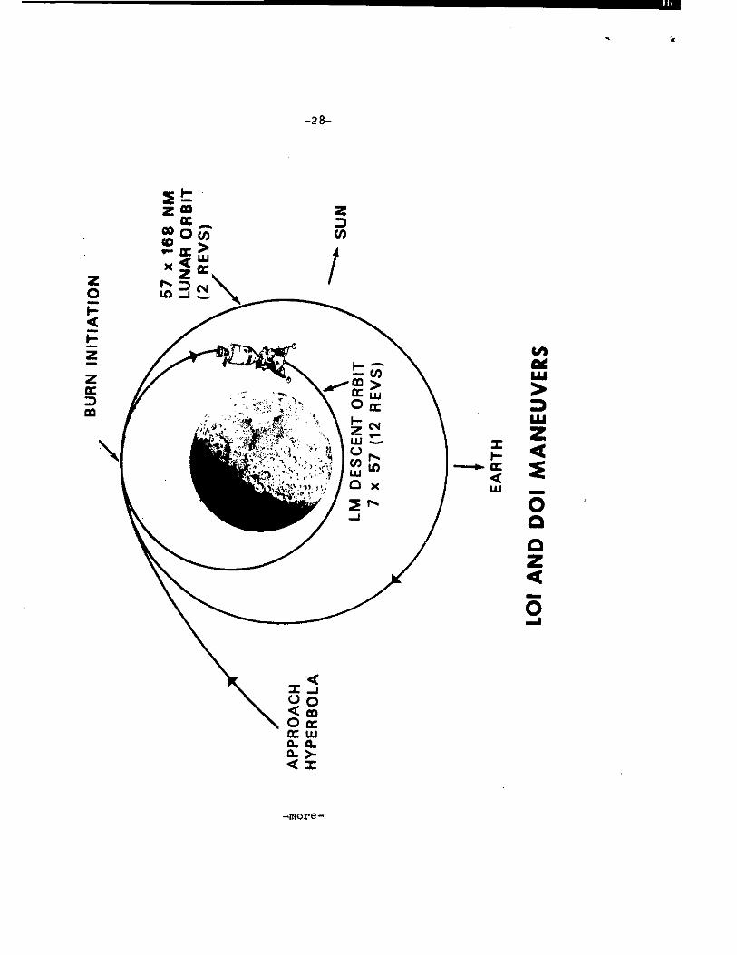
Lunar Orbit Insertion (LOl)
The lunar orbit insertion burn will be made at 77:25 GET at an altitude of about 85 nm above the Moon. The LOl burn will have a nominal retrograde velocity change of 2815 fps and will insert Apollo 13 into a 57x168 nm elliptical lunar orbit.
Descent Orbit Insertion (DOI)
A 213 fps SPS retrograde burn at 81:45 GET will place the CSM /LM into a 7x57 nm lunar orbit from which the LM will begin the later powered descent to landing. In Apollos 11 and 12, DOI was a separate maneuver using the LM descent engine. The Apollo 13 DOI maneuver in effect is a combination L01-2 and DOI and produces two benefits: conserves LM descent propellant that would have been used for DOI and makes this propellant available for additional hover time near the surface, and allows 11 lunar revolutions of spacecraft tracking in the descent orbit to enhance position/velocity (state vector) data for updating the LM guidance computer during the descent and landing phase.
Lunar Module Separation
The lunar module will be manned and checked out for un-docking and subsequent landing on the lunar surface north of the crater, Fra Mauro. Undocking during the 12th revolution will take place at 99:16 GET. A radially downward service module RCS burn of 1 fps will place the CSM on an equiperiod orbit with a maximum separation of 2.5 nm.
CSM Circularization
During the 12th revolution, a 70 fps posigrade SPS burn at 100:35 GET will place the CSM into 52x62 nm lunar orbit, which because of perturbations of the lunar gravitational po-tential, should become nearly circular at the time of rendez-vous with the LM.
-more-
AN
D D
OI
MA
NE
UV
ER
S
BU
RN
IN
I TIA
TIO
N
-2 8-
2 z Oa Z
CC Z CO 0 a V)
Z CC X < "j
LO —I :Z. N. M ru
-more-
0
-29-
Power Descent Initiation (PDI), Lunar Landing
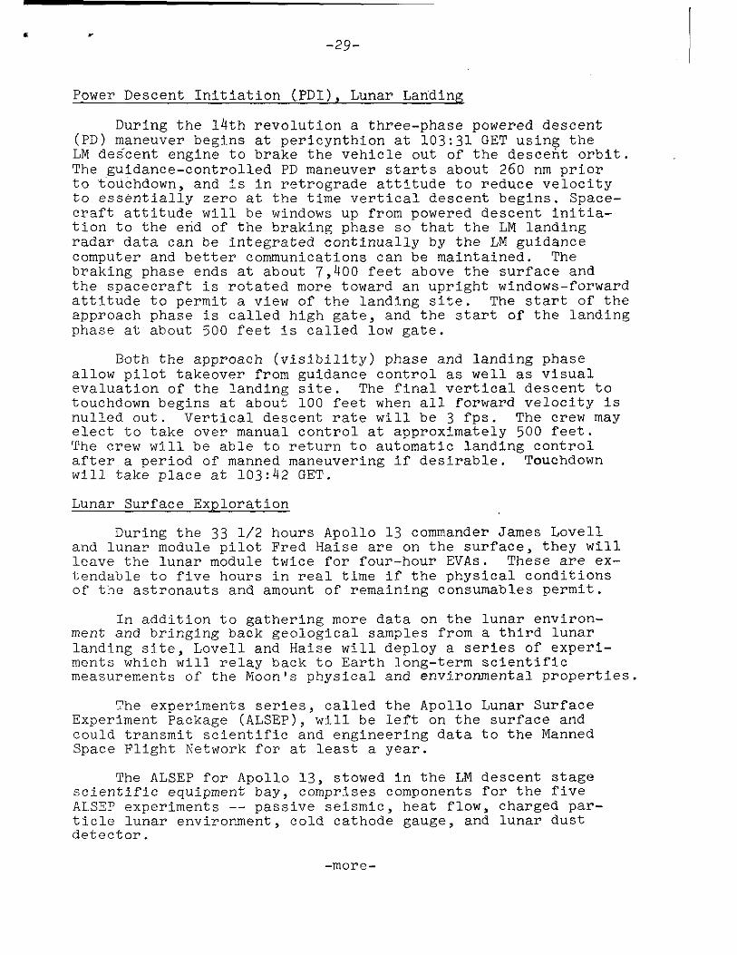
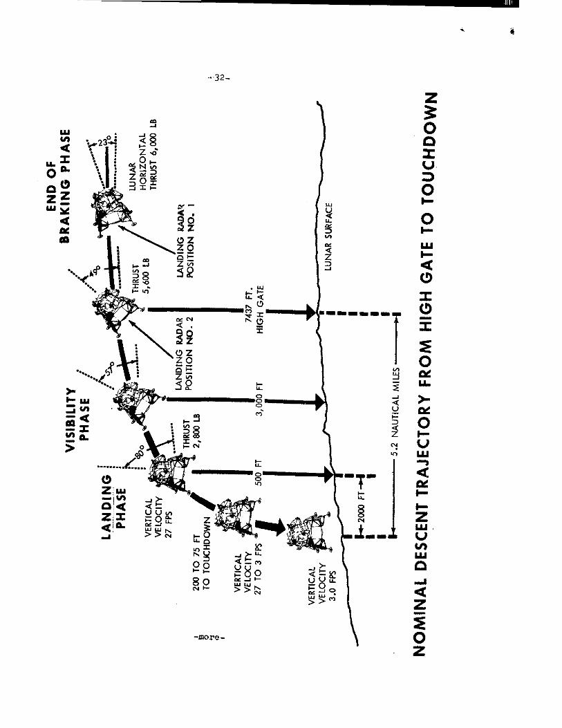
During the 14th revolution a three-phase powered descent (PD) maneuver begins at pericynthion at 103:31 GET using the LM decent engine to brake the vehicle out of the descent orbit. The guidance-controlled PD maneuver starts about 260 nm prior to touchdown, and is in retrograde attitude to reduce velocity to essentially zero at the time vertical descent begins. Space-craft attitude will be windows up from powered descent initia-tion to the end of the braking phase so that the LM landing radar data can be integrated continually by the LM guidance computer and better communications can be maintained. The braking phase ends at about 7,400 feet above the surface and the spacecraft is rotated more toward an upright windows-forward attitude to permit a view of the landing site. The start of the approach phase is called high gate, and the start of the landing phase at about 500 feet is called low gate.
Both the approach (visibility) phase and landing phase allow pilot takeover from guidance control as well as visual evaluation of the landing site. The final vertical descent to touchdown begins at about 100 feet when all forward velocity is nulled out. Vertical descent rate will be 3 fps. The crew may elect to take over manual control at approximately 500 feet. The crew will be able to return to automatic landing control after a period of manned maneuvering if desirable. Touchdown will take place at 103:42 GET.
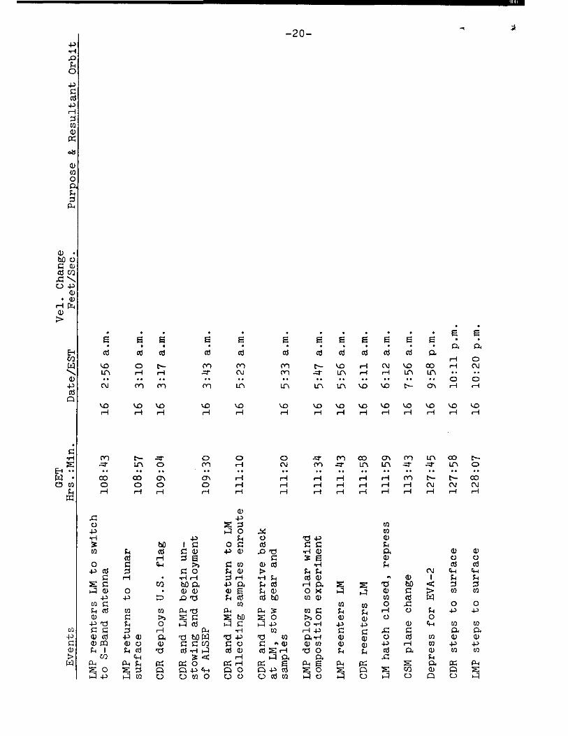
Lunar Surface Exploration
During the 33 1/2 hours Apollo 13 commander James Lovell and lunar module pilot Fred Haise are on the surface, they will leave the lunar module twice for four-hour EVAs. These are ex-tendable to five hours in real time if the physical conditions of the astronauts and amount of remaining consumables permit.
In addition to gathering more data on the lunar environ-ment and bringing back geological samples from a third lunar landing site, Lovell and Haise will deploy a series of experi-ments which will relay back to Earth long-term scientific measurements of the Moon's physical and environmental properties.
The experiments series, called the Apollo Lunar Surface Experiment Package (ALSEP), will be left on the surface and could transmit scientific and engineering data to the Manned Space Flight Network for at least a year.
The ALSEP for Apollo 13, stowed in the LM descent stage scientific equipment bay, comprises components for the five ALSEP experiments -- passive seismic, heat flow, charged par-ticle lunar environment, cold cathode gauge, and lunar dust detector.
-more-

, 4,,
-30-
---0* ,:: LIJ
LM D
ESC
EN
T O
RB
ITA
L E
VE
NT
S
-more-

AY
' r4 WI N o Z Z Z to■ 1 2 I
Z 7.. Z : V 2 9" " 41. l'''.
AAA . •••• A N. A
000•1IMA. r.
.,..r. it ..1 v r• 0 A ,,n in , ei, 1 -I et a 1
7 1 V
9" g g g .19. It a li
AI. m
MnS
w, N
IA .. 0 , A gr A A -4 •••• .
.u1
1113A3
THR
OTT
LE
TO L
u iS
ikil:
LI T
HR
UST
LAND
ING
RAD
AR
AL
TIT
UD
E u
PDA
TE
TH
ROTT
LE
RE
CO
VE
RY
LAN
DING
RA
M V
ELO
CIT
Y U
PDA
TE
HO
RIZ
ON
VI S
IBIL
ITY
$410
10,1
1
POW
ERE
D DE
SCEN
T PR
OFI
LE
-more-
3 2 -
NO
MIN
AL
DE
SC
EN
T T
RA
JEC
TO
RY
FR
OM
HIG
H G
AT
E T
O T
OU
CH
DO
WN

-33-
These experiments are aimed toward determining the structure and state of the lunar interior, the composition and structure of the lunar surface and processes which modify the surface, and evolutionary sequence leading to the Moon's present characteristics. The Passive Seismic Experiment will become the second point in a lunar seismic net begun with the first ALSEP at the Surveyor III landing site of Apollo 12. Those two seismometers must continue to operate until the next seismometer is emplaced to complete the three-station set. The heat flow experiment includes drilling two 10-foot holes with the lunar surface drill.
While on the surface, the crew's operating radius will be limited by the range provided by the oxygen purge system (OPS), the reserve backup for each man's portable life support system (PLSS) backpack. The OPS supplies 45 minutes ofemergency breathing oxygen and suit pressure.
Among other tasks assigned to Lovell and Haise for the two EVA periods are:
*Collect a contingency sample of about two pounds of lunar material.
*Gather about 95 pounds of representative lunar surface material, including core samples, individual rock samples and fine-grained fragments from the Fra Mauro hilly uplands site. The crew will photograph thoroughly the areas from which sam-ples are taken.
*Make observations and gather data on the mechanical properties and terrain characteristics of the lunar surface and conducting other lunar field geological surveys, including digging a two-foot deep trench for a soil mechanics investigation.
*Photograph with lunar stereo closeup camera small geological features that would be destroyed in any attempts to gather them for return to Earth.
*Deploy and retrieve a windowshade-like solar wind compo-sition experiment similar to the ones used in Apollos 11 and 12.
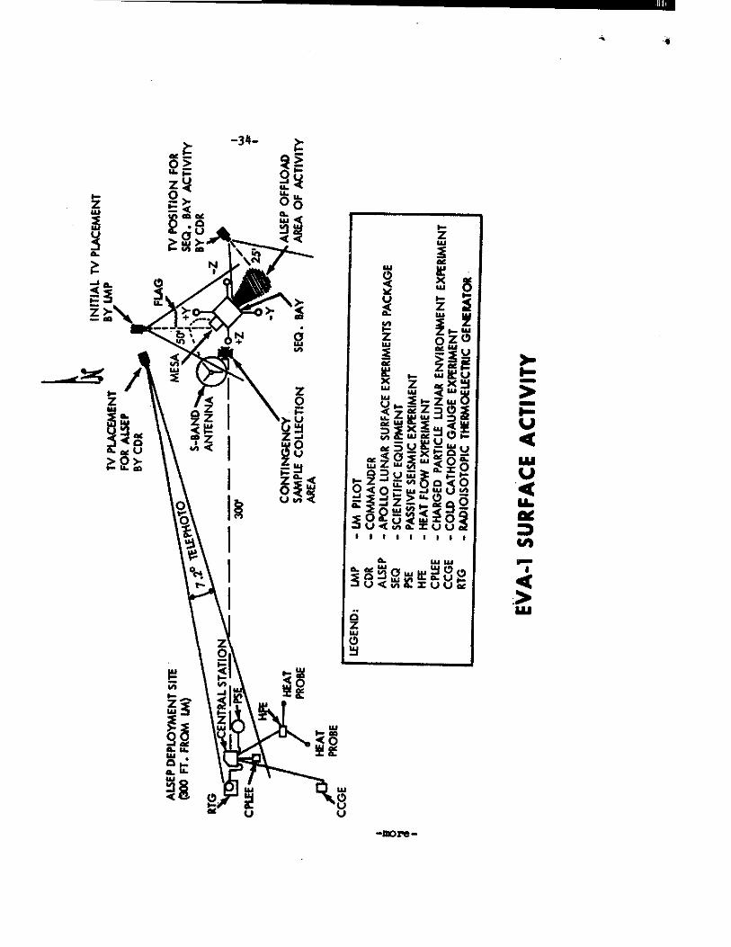
Early in the first EVA, Lovell and Haise will set up the erectable S--Band an'.;enna near the LM for relaying voice, TV, and LM telemetry to MSFN stations. After the antenna is de-ployed, Haise will climb back into the LM to switch from the LM steerable S-Band antenna to the erectable antenna while Lovell makes final adjustments to the antenna's alignment. Haise will then rejoin Lovell on the lunar surface to set up a United States flag and continue with EVA tasks.
-more-
--more-
EV
A- 1
SU
RFA
CE
AC
TIV
ITY
z 3
Ma
z
Ve4 0 VA L9I 'Vere V MU d
6 z 0
EV
A- 1
TR
AVE
RSE
-35-
DI R
EC
TIO
N

♦
- 36- - 36.-
14.1
• IR \ 8
(C31 . • MM. • MN
/\° ce iu Z
N
2
0 I to
geleS).3.2L;re).
4 6.0 •,••■
•••
0
■
• •••
Ik ■
-(4, ‘ 1 / \ 00,,,,.. /
'"?" ■ t be i
\ 1 // NIr.
I / lab 2 ' —:„..w
a 5 4:.., 4 ••••' , i,_
0 , v., ....,
IA CC
\ Cs- < .32 ee I- 11,1
•'' ", '- .•
1
V
-more -
-37-
Red stripes around the elbows and knees of Lovell's pressure suit will permit crew recognition during EVA tele-vision transmissions and on photographs.
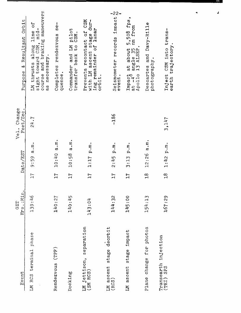
Ascent, Lunar Orbit Rendezvous
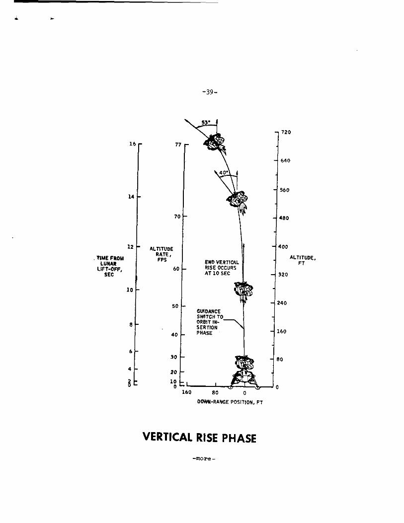
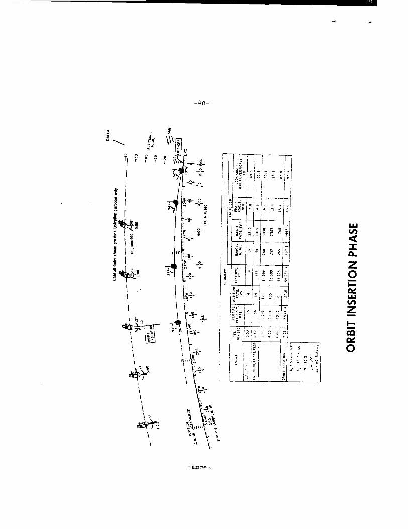
Following the 33-hour lunar stay the LM ascent stage will lift off the lunar surface to begin the rendezvous sequence with the orbiting CSM. Ignition of the LM ascent engine will be at 137:09 for a seven minute eight second burn attaining a total velocity of 6,044 fps. Powered ascent is in two phases: vertical ascent for terrain clearance and the orbital inser-tion phase. Pitchover along the desired launch azimuth begins as the vertical ascent rate reaches 50 fps about 10 seconds after liftoff at about 272 feet in altitude. Insertion into a 9x44 nm lunar orbit will take place about 166 nm west of the landing site.
Following LM insertion into lunar orbit, the LM crew will compute onboard the major maneuvers for rendezvous with the CSM which is about 267 nm ahead of and 51 miles above the LM at this point. All maneuvers in the sequences will be made with the LM RCS thrusters. The premission rendezvous sequence maneuvers, time, and velocities, which likely will differ slightly in real time, are as follows:
Concentric sequence initiate (CSI): At first LM apolune after insertion, 138:19 GET, 50 fps posigrade, following some 20 minutes of LM rendezvous radar tracking and CSM sextant/VHF ranging navigation. CSI will be targeted to place the LM in an orbit 15 nm below the CSM at the time of the later constant delta height (CDH) maneuver (139:04).
The CSI burn may also initiate corrections for any out-of-plane dispersions resulting from insertion azimuth errors. The resulting LM orbit after CSI will be 45)(43.5 nm and will have a catchup rate to the CSM of about 120 feet per second.
Terminal phase initiation (TPI): This maneuver occurs at 139:46 and adds 24.7 fps along the line of sight toward the CSM when the elevation angle to the CSM reaches 26.6 degrees. The LM orbit becomes 61x44 nm and the catchup rate to the CSM decreases to a closing rate of 133 fps.
Midcourse correction maneuvers will be made if needed, fol-lowed by four braking maneuvers. Docking nominally will take place at 140:25 GET to end the three and one-half hour rendez-vous sequence.
The LM ascent stage will be jettisoned at 143:04 GET and a CSM RCS 1.0 fps maneuver will provide separation.
-more-

LM
ASC
EN
T
-38-
-more-
480
160
240
GUIDANCE SWITCH TO ORBIT IN-SERTION PHASE
80
0 80 160
-39
•
720
16 r 77 e-
640
560
14
400
ALTITUDE, END VERTICAL FT RISE OCCURS AT 10 SEC 320
10 (- 0 """
20
70
- ALTITUDE RATE, FPS
60
50
40
30
12
, TIME FROM LUNAR
LIFT-OFF, SEC
10
8
6
4
00W1i-RANGE POSITION, FT
VERTICAL RISE PHASE
-more -
O;
co
0 N
SER
TIO
N P
HA
SE
4
W W
"
,9, '4"• ro O
ao
'1 1 1
05 a
a-
O
0 6)
6
-more

-41-

-42-
Ascent Stage Deorbit
Prior to transferring to the command module, the LM crew will set up the LM guidance system to maintain the ascent stage in an inertial attitude. At about 144:32 GET the LM RCS thrus-ters will ignite on ground command for 186 fps retrograde burn targeted for ascent stage impact at 145:00 about 35 miles from the landing site. The burn will have a small out-of-plane north component so that the ground track will include the original landing site. The ascent stage will impact at about 5508 fps at an angle of four degrees relative to the local horizontal. The ascent stage deorbit serves to remove debris from lunar or-bit. Impacting an object with a known velocity and mass near the landing site will provide experimenters with an event for calibrating readouts from the ALSEP seismometer left behind.
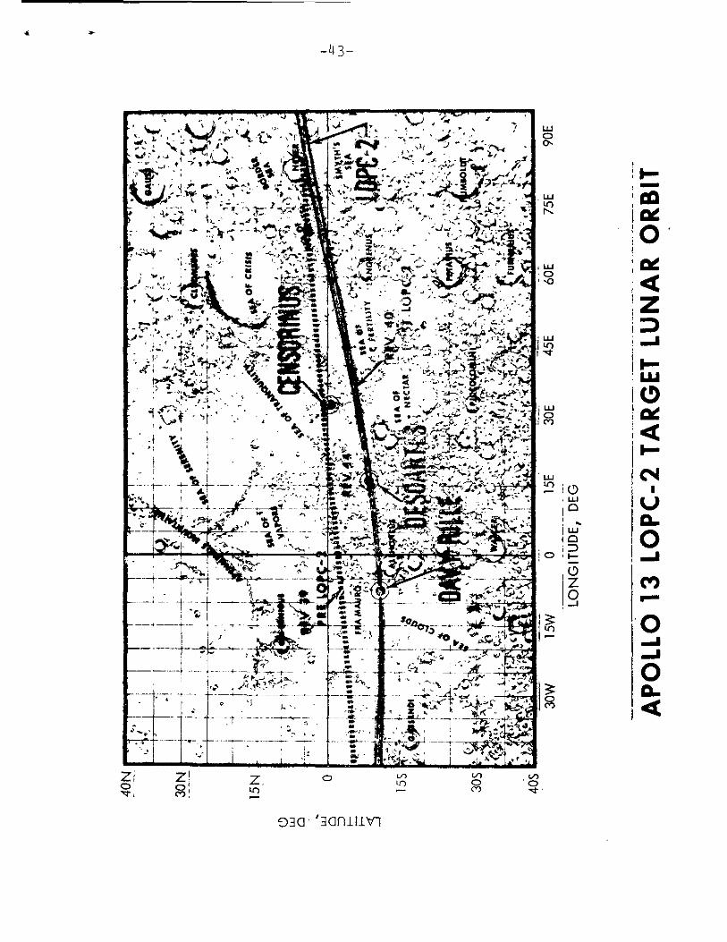
A plane change maneuver at 154:13 GET will place the CSM on an orbital track passing directly over the crater Descartes and Davy Rille eight revolutions later for photographs from orbit. The maneuver will be a 825 fps/SPS burn out of plane for a plane change of 8.8 degrees, and will result in an orbit inclination of 11.4 degrees.
Transearth Injection (TEI)
The nominal transearth injection burn will be at 167:29 GET following 90 hours in lunar orbit. TEI will take place on the lunar farside, will be a 3,147 fps posigrade SPS burn of two minutes 15 seconds duration and will produce an entry velocity of 36,129 fps after a 72 hours transearth flight time.
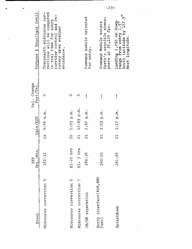
Transearth Coast
Three entry corridor-control transearth midcourse correc-tion burns will be made if needed: MCC-5 at TEI+15 hours, MCC-6 at entry interface (EI) -22 hours and MCC-7 at EI -3 hrs.
Entry, Landing
Apollo 13 will encounter the Earth's atmosphere (400,000 feet) at 240:50 GET at a velocity of 36,129 fps and will land approximately 1,250 nm downrange from the entry-interface point using the spacecraft's lifting characteristics to reach the landing point. Splashdown will be at 241:04 at 1.5 degrees South latitude by 157.5 degrees West longitude.
-more-
030 .
0 Cr)
V)
-43-
AP
OLL
O 1
3 LO
PC
-2 T
AR
GET
LU
NA
R O
RB
IT

Recovery Operations
Launch abort landing areas extend downrange 3,400 nautical miles from Kennedy Space Center, fanwise 50 nm miles above and below the limits of the variable launch azimuth (72-96 degrees) in the Atlantic Ocean. On station in the launch abort area will be the destroyer USS New.
The landing platform-helicopter (LPH) Iwo Jima, Apollo 13 prime recovery ship, will be stationed near the Pacific Ocean end-of-mission aiming point prior entry.
Splashdown for a full-duration lunar landing mission launched on time April 11 will be at one degree 34 minutes South by 157 degrees 30 minutes West about 180 nautical miles South of Christmas Island, at 241:04 GET (3:17 p.m. EST) April 21.
In addition to the primary recovery vessel located on the mid-Pacific recovery line and the surface vessel in the launch abort area, eight HC-130 aircraft will be on standby at five staging bases around the Earth: Guam; Hawaii; Azores; Ascension Island;and Florida.
Apollo 13 recovery operations will be directed from the Recovery Operations Control Room in the Mission Control Center, supported by the Atlantic Recovery Control Center, Norfolk, Va., and the Pacific Recovery Control Center, Kunia, Hawaii.
After splashdown, the Apollo 13 crew will don clean cover-alls and filter masks passed to them through the spacecraft hatch by a recovery swimmer. The crew will be carried by heli-copter to the Iwo Jima where they will enter a Mobile Quaran-tine Facility (MQF) about 90 minutes after landing.

s
8
0 CV
Long
itude
, de
g
s M
AN
EUV
ER
FO
OT
PRIN
T A
ND
NO
MIN
AL
GR
OU
ND
TR
AC
K
a -a-
-LI 5 -
•I I- -1
•
1W • N
I
• IIY
MY
1-1
I
RA
NG
E LI
•
1'1'.
H
il
l 1
LA
ND
ING
TA
R(
1 ° 3
4' S
, 15
7 °
_
1 O
U N
D T
RA4
•
_
,,,,,,,,..,..
0 C:, 0 CV es,
HDION HINDS
Bap lapnwoi 3gapog0
-more-
-46-
APOLLO 13 ONBOARD TELEVISION
Apollo 13 wf_11 carry two color and one black-and-white television cameras. One color camera will be used for command module cabin interiors and out-the-window Earth/ Moon telecasts, and the other color camera will be stowed in the LM descent stage from where it will view the astronaut initiate egress to the lunar surface and later will be de-ployed on a tripod to transmit a real-time picture of the two periods of lunar surface EVA. The black-and-white camera will be carried f_n the LM cabin. It will only be used as a backup to the lunar surface color camera.
The two color TV cameras are essentially identical, except for addit -...onal thermal protection on the lunar surface camera. Built by Westinghouse Electric Corp., Aerospace Division, Baltimore, Md., the color cameras output a standard 525-line, 30 frame-per-second signal in color by use of a rotating color wheel system.
The color TV cameras weigh 12 pounds and are fitted with zoom lenses for uideangle or closeup fields of view. The CM camee'a Ls 'itted with a three-inch monitor for framing and focusing. The lunar surface color camera has 100 feet of cable
The backup black-and-white lunar surface TV camera, also built by Westinghouse, is of the same type used in the first manned lunar landing in Apollo 11. It weighs 7.25 pounds and draws 6.5 watts of 24-32 volts DC power. Scan rate is 10 frames-per--second at 325 lines-per-frame. The camera body is 10.6 inches long, 6.5 inches wide and 3.4 inches deep, and is fitted uith bayonet-mount wideangle and lunar day lenses.
During the two lunar surface EVA periods, Apollo 13 commander Lovell will be recognizable by red stripes around the elbows and knees of his pressure suit.
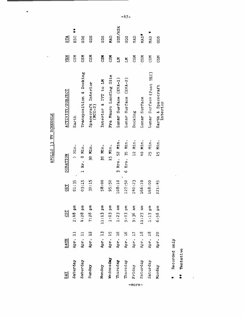
The following is a preliminary plan for TV transmissions based upon a 2:13 p.m. EST April 11 launch.
SCHE
DULE
APOLLO 13
Tenta
tive
Reco
rde
d on
ly
4-) S1 cd
ACTIVITY/SUBJECT
Trans
pos
itio
n & Do
cking
IVT
to LM
Interio
r
-)47-
E-144 I 0 V)
V) g=1 • 1=1 A r
•
=1 C:) A < d < 0 0 0 0
Cf) C
• C
) v/] rum cn cn C) 0 0 i4 0 U 0
DURA
TION
Fra Mauro Landin
g Site
E 0 cd LL
4.4
O ► 4 C21 L
unar Surfa
ce
Lunar
Su
rfa
ce (
Po
st
Interior
. . .
C C C C C ri ri ri H H H
C C C Z C E E E X E E ri H H H H --. : z E (NI tn n./ 0 in
LC1 M H -- N H ,:-- CO 0 0 LL
rn rn H
0 cr)
FA t4 %-. = =
rn +.0
In LC\ LC\ 0 CD 0 0 Crl 0 0 in M H H c0 LC \ ri Lf1 N .-- 0 ---
El 1 • • . 4
W ri cel 0 CO Lrt CID N - 0 +0 CC) .1
0 0 0 CY) in, 0 0 N -a' kb ,40 N H H H rel H CU
E e E E E E E E E E E R. P. Q. O. a cd 0. Cd oi 0. 0.
PI c.1 op co co rn rn n'") rn %,c) cr) ce) oo
U a• N N ,-4 gz. (N) .0 rr CV H Ir■
N H H H cr., ccr ■ H H ',0 r-I ri
H H N CTI N- co CO - H N
I
;
a. ca
. . $.1 -1 P4 R. 40 .0 <
• • ▪ $.4 F-1 ;•1
0. 0. a R. R. < < < .0 <
cd›. >1 "t >s >2. al .0 0 0 cd 0
'0 '0 P.4 >4 0 '0 '0 >, .0 '0 ›.. ti r/ cd cd a) 0 0 rd F, I. cd O 0 '0 'a C FA S-I Z Z Tri I
< 0 al S o a)
•
F-I
▪
cd c
▪
d 0 Co rol En E N cr., r1) ri) E
—ITIOre-
- 4 8-
APOLLO 13 SCIENCE
Lunar Orbital Photography
Science experiments and photographic tasks will be conducted from the CSM during the Apollo 13 mission. During the translunar phase of the mission, photography will be taken of the Earth as well as various operational photography.
During lunar orbit, various lunar surface features including candidate landing sites Censorinus, Descartes and Davy Rille and the Apollo 11 and 12 landing sites will be photographed with the Lunar Topographic Camera. In addition, five astronomical phenomena will be photographed:
1) Photographs will be taken of the solar corona using the Moon as an occulting edge to block out the solar disk.
Photography will be taken of the zodiacal light which is believed to originate from reflected sunlight in the astoroid belt. Earth observation of zodiacal light is inconclusive due to atmospheric distortion.
3) Photography will be taken of lunar limb brightening, which appears as bright rim light above the horizon following lunar sunset.
4) Photographs will be taken of the Comet J.C. Bennett, 19691 which should be visible from lunar orbit during the Apollo 13 mission.
5) Photographs will be taken of the region of Gegenschein which is a faint light source covering a 20 ° field of view about the Earth-Sun line on the opposite side of the Earth from the Sun (anti-solar axis). One of the theories for the Gegenschein source is the existence of trapped particles of matter at the Moulton point which produce brightness due to reflected sunlight. The Moulton point is a theoretical point located 940,000 statute miles from the Earth along the anti-solar axis at which the sum of all gravitational forces is zero. From the vantage point of lunar orbit, the Moulton point region may be photographed from approxi-mately 15 ° off the Earth/Sun line. These photographs should show if Gegenschein results from the Moulton point theory or from zodiacal light or a similar source.
-more-
-49-
Photographic studies will be made on Apollo 13 of the ice particle flow following a water dump and of the gaseous cloud which surrounds a manned spacecraft in a vacuum and results from liquid dumps, outgassing, etc.
In addition to the photographic studies, an experiment will be conducted with the CSM VHF communications link. During this experiment, the VHF signal will be reflected from the lunar surface and received by a 150-foot antenna on Earth. By analysis of the wavelength of the received signal, certain lunar subsurface characteristics may be discernible such as the depth of the lunar regolith layer. This experiment is called VHF Bistatic Radar.
Charged Particle Lunar Environment Experiment (CPLEE)
The scientific objective of the Charged Particle Lunar Environment Experiment is to measure the particle energies of protons and electrons that reach the lunar surface from the Sun. Increased knowledge on the energy distribution of these particles will help us understand how they perturb the Earth-Moon system. At some point electrons and protons in the magnetospheric tail of the Earth are accelerated and plunge into the terrestrial atmosphere causing the spectacular auroras and the Van Allen radiation. When the Moon is in interplanetary space the CPLEE measures proton and electrons from solar flares which results in magnetic storms in the Earth's atmosphere. Similar instruments have been flown on Javelin rockets and on satellites. The lunar surface, however, allows data to be gathered over a long period of time and from a relatively stable platform in space.
To study these phenomena, the CPLEE measures the energy of protons and electrons simultaneously from 50 electron volts to 50,000 electron volts (50Kev) : The solar radiation phenomena measured are as follows: —
a. Solar wind electrons and protons 50ev-5Kev.
b. Thermalized solar wind protons and electrons 50ev-10Kev.
c. Magnetospheric tail particles 50ev to 50Kev.
d. Low energy solar cosmic rays 40ev-50Kev.
-more-
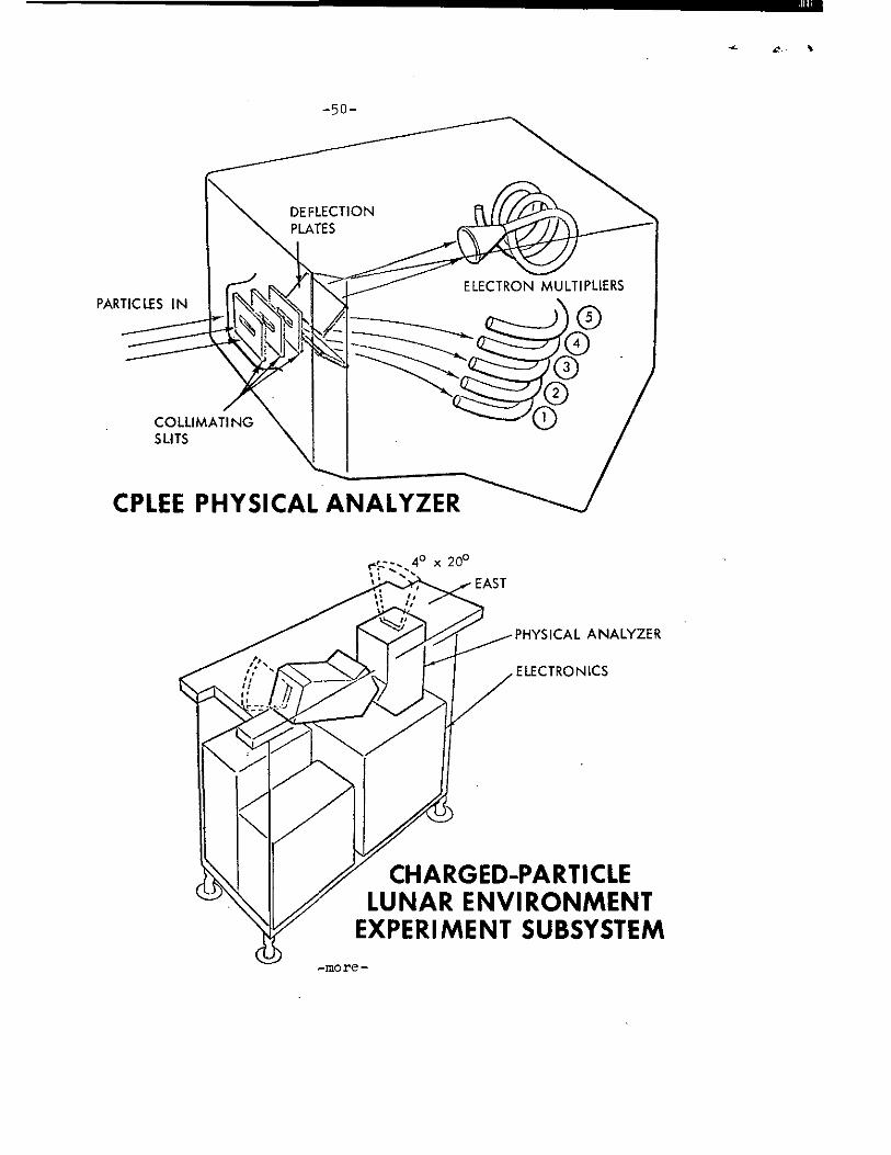
PHYSICAL ANALYZER
ELECTRONICS
CHARGED-PARTICLE LUNAR ENVIRONMENT
EXPERIMENT SUBSYSTEM
-50-
-more-
-51-
This experiment is distinct from the ALSEP Solar Wind Spectrometer (SWS) flown on Apollo 12 which measures direction as well as energy levels. The SWS measures elec-trons from 10.5ev to 1,400ev and protons from 75ev to 10,000ev.
The detector package contains two spectrometers providing data on the direction of the incoming flux.
Each spectrometer has six particle detectors: five C-shaped channeltron photon-multipliers and one funneltron, a helical shaped photon multiplier. Particles of a given charge and different energies on entering the spectrometer are subject to varying voltages and deflected toward the five channeltrons while particles of the opposite charge are deflected toward the funneltron. Thus electrons and protons are measured simultaneously in six different energy levels. The voltages are changed over six steps; +35V, +350 volts and +3500V. In this way electrons and protons are measured from 50ev to 70Kev in a period of less than 20 seconds.
The channeltron is a glass capillary tube having an inside diameter of about one millimeter and a length of 10 centimeters. The helical funneltron has an opening of 8mm. When a voltage is applied between the ends of the tube, an electric field is established down its length. Charged particles entering the tube are amplified by a factor of 10 8.
The spectrometers have two ranges of sensitivity and can
measure fluxes between 10 4 and 10 10 particles/cm2-sec-steradian.
The charged particle lunar environment experiment (CPLEE) and data analysis are the responsibility of Dr. Brian O'Brien, University of Sydney (Australia) and Dr. David Reasoner, Rice University, with Dr. O'Brien assuming the role of Principal Investigator.
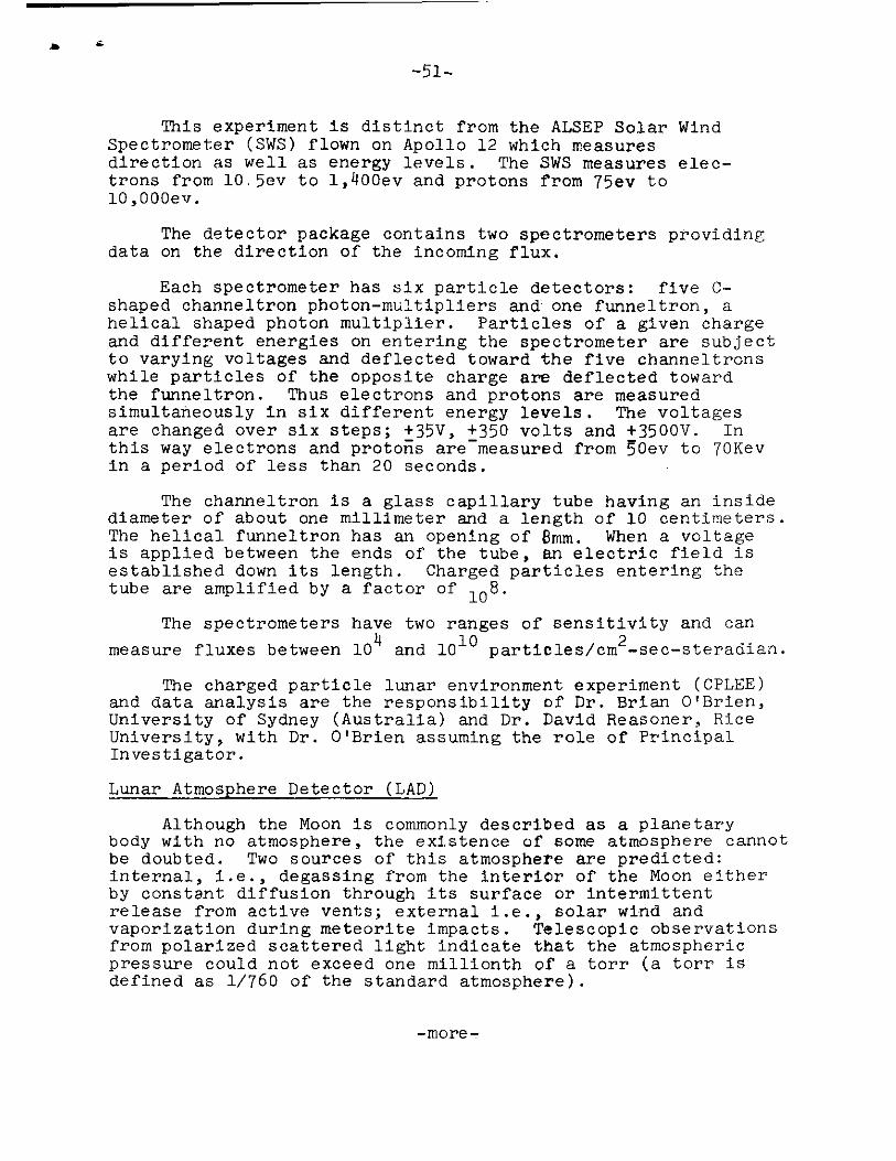
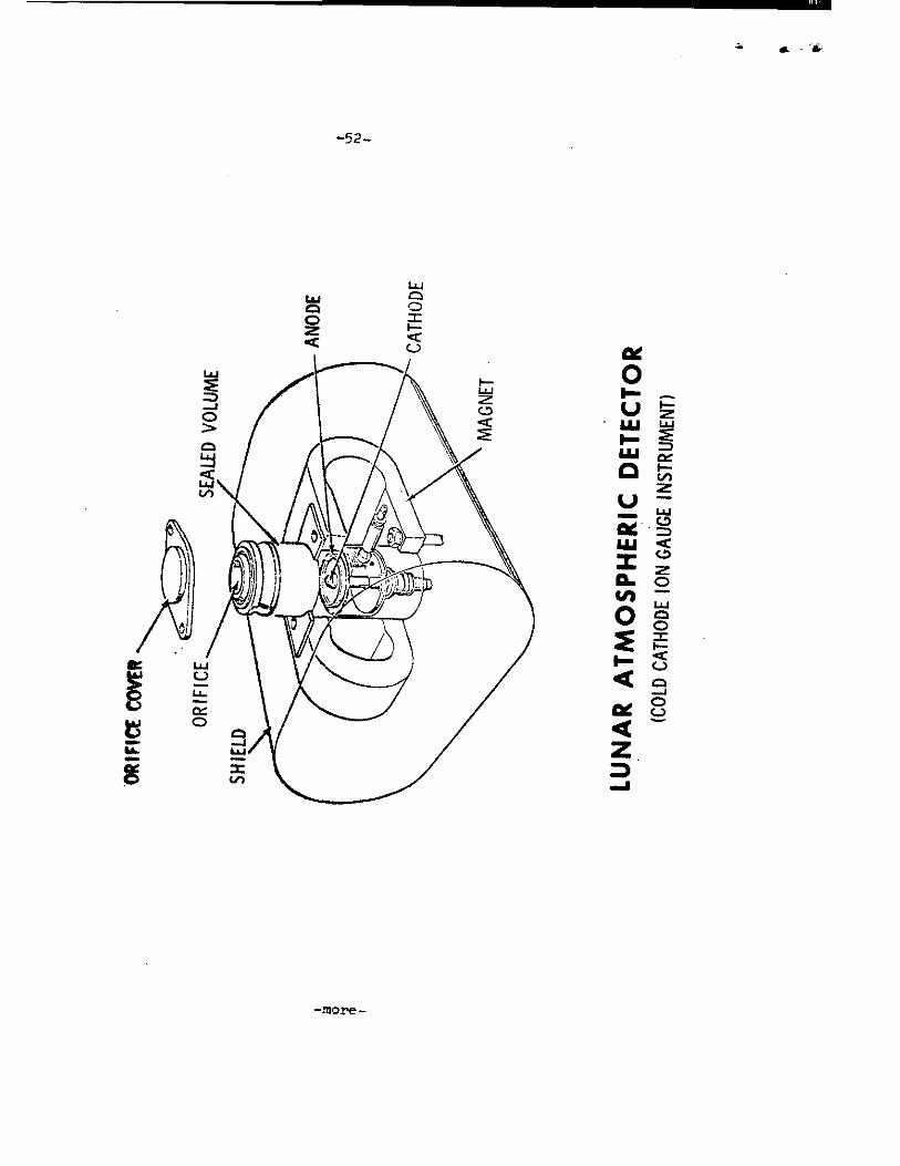
Lunar Atmosphere Detector (LAD)
Although the Moon is commonly described as a planetary body with no atmosphere, the existence of some atmosphere cannot be doubted. Two sources of this atmosphere are predicted: internal, i.e., degassing from the interior of the Moon either by constant diffusion through its surface or intermittent release from active vents; external i.e., solar wind and vaporization during meteorite impacts. Telescopic observations from polarized scattered light indicate that the atmospheric pressure could not exceed one millionth of a torr (a torr is defined as 1/760 of the standard atmosphere).
-more-
-52-
- 5 3-
Measurements will be of the greatest significance if it turns out through later orbital sensors that they are of internal origin. The Earth's atmosphere and oceans have been released from the Earth's interior by degassing. The most certain source, however, is the solar wind whose ionized particles become neutralized in the lunar atmosphere and then are released as neutral gases. Neon is the predominant gas expected. Lighter gases such as hydrogen and helium escape and heavier ones statistically should be present in small quantities. Neutral particles are ionized in the lunar atmos-phere, further reducing the numbers present; others will escape as the temperature rises (and concentrate near the surface when it falls).
The LAD utilizes a cold cathode ionization gauge to measure the density of neutral particles at the lunar surface and the variations in density association with lunar phase or solar activity. The ionization gauge is basically a crossed electro-magnetic field device. Electrons in the gauge are accelerated by the combined magnetic and electric fields pro-ducing a collision are collected by the cathode where they form a flow of positive ions. The positive ions current is found to be proportional to the density of the gas molecules entering the gauge. In addition, the gauge temperature is read over the range of -90° to 125°C with 4- 5°C accuracy.
From the density and temperature data the pressure of the ambient lunar atmosphere can then be calculated. Chemical composition of the atmosphere however is not directly measured but the gauge has been calibrated for each gas it is expected to encounter on the lunar surface and some estimates can be made of the chemical composition. Any one of seven different dynamic ranges may be selected permitting detection of neutral
particles from 10-6 Torr (highest pressure predicted) to 10-12
Torr (maximum capability of gauge). For pressure greater than
- 10 1 ° Torr accuracies of - 30% will be obtained; for pressures
less then 10 -10 Torr accuracies - 50% will be obtained. The experiment, therefore, will reduce the present uncertainty from a magnitude to a factor.
The Lunar Atmosphere Detector (LAD) and data are the responsibility of Francis Johnson, University of Texas (Dallas) and Dallas Evans, Manned Spacecraft Center, with Dr. Johnson serving as Principal Investigator.
-more-

-54-
Lunar Heat Flow ExperiMent (HFE)
The scientific objective of the Heat Flow experiment is to measure the steady-state heat flow from the lunar interior. Two predicted sources of heat are: 1) original heat at the time of the Moon's formation and 2) radioactivity. Scientists believe that heat could have been generated by the infalling of material and its subsequent compaction as the Moon was formed. Moreover, varying amounts of the radioactive elements uranium, thorium and potassium were found present in the Apollo 11 and 12 lunar samples which if present at depth, would supply significant amounts of heat. No simple way has been devised for relating the contribution of each of these sources to the present rate of heat loss. In addition to temperature, the experiment is capable of measuring the thermal conductivity of the lunar rock material.
The combined measurement of temperature and thermal conductivity gives the net heat flux from the lunar interior through the lunar surface. Similar measurements on Earth have contributed basic information to our understanding of volcanoes, earthquakes and mountain building processes. In conjunction with the seismic and magnetic data obtained on other lunar experiments the values derived from the heat flow measurements will help scientists to build more exact models of the Moon and thereby give us a better understanding of its origin and history.
The Heat Flow experiment consists of instrument probes, electronics and emplacement tool and the lunar surface drill. Each of two probes is connected by a cable to an electronics box which rests on the lunar surface. The electronics, which provide control, monitoring and data processing for the experiment, is connected to the ALSEP central station.
Each probe consists of two identical 20-inch (50 cm) long sections each of which contains a "gradient" sensor bridge, a "ring" sensor bridge and two heaters. Each bridge consists of four platinum resistors mounted in a thin-walled fiberglass cylindrical shell. Adjacent areas of the bridge are located in sensors at opposite ends of the 20-inch fiber-glass probe sheath. Gradient bridges consequently measure the temperature difference between two sensor locations.
-more-
-55-
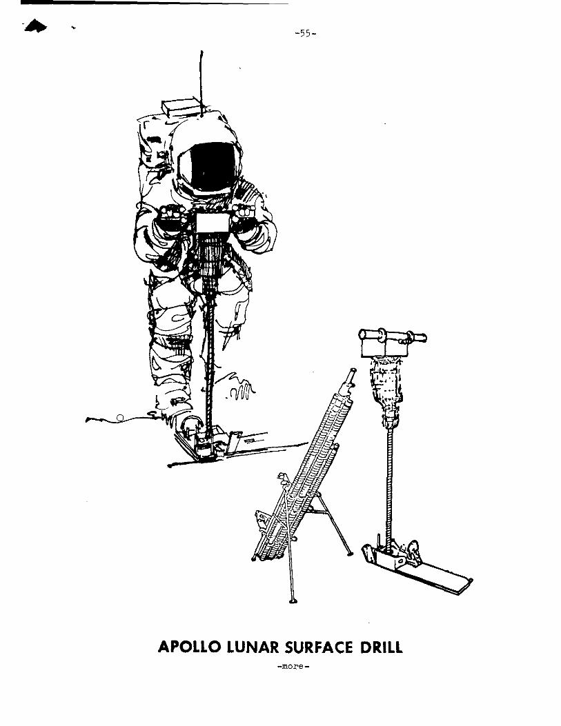
APOLLO LUNAR SURFACE DRILL

SUNSHIELD
THERMAL MASK REFLECTOR
CAB LE BRACKET REMOVED DURING DEPLOYMENT
LUNAR SURFACE
RING SENSOR (4/PROBE)
RADIATION SHIELD GRADIENT
SENSOR
4/PROBE (INSIDE)
FLEXIBLE SPRING
HEATER COI LS (OUTSIDE)
PROBE STOP
HEAT FLOW EXPERIMENT
TO ELECTRONICS
RADIATION SHIELD
THERMOCOUPLES 25 .6, 45.3
A & 65.0 IN .
BOVE PROBE
PROBE
-56 -
PROBE PACKAGE
ELECTRON ICS
PROBE CARRYING PACKAGE CABLE TRAY
PAC KAGE
(CONTAINS 2 PROBES & EMPLACEMENT TOOL)
-more
-57-
In thermal conductivity measurements at very low values a heater surrounding the gradient sensor is energized with 0.002 watts and the gradient sensor values monitored. The rise in temperature of the gradient sensor is a function of the thermal conductivity of the surrounding lunar material. For higher range of values, the heater is energized at 0.5 watts of heat and monitored by a ring sensor. The rate of temperature rise, monitored by the ring sensor is a function of the thermal conductivity of the surrounding lunar material. The ring sensor, approximately four inches from the heater, is also a platinum resistor. A total of eight thermal conduc-tivity measurements can be made. The thermal conductivity mode of the experiment will be implemented about twenty days (500 hours) after. deployment. This is to allow sufficient time for the perturbing effects of drilling and emplacing the probe in the borehole to decay; i.e., for the probe and casings to come to equilibrium with the lunar subsurface.
A 30-foot (10 meter) cable connects each probe to the electronics box. In the upper six feet of the borehole the cable contains four evenly spaced thermocouples: at the top of the probe; at 26" (65 cm), 45" (115 cm), and 66" (165 cm). The thermocopules will measure temperature transients pro- pagating downward from the lunar surface. The reference junction temperature for each thermocouple is located in the electronics box. In fact, the feasibility of making a heat flow measure-ment depends to a large degree on the low thermal conductivity of the lunar surface layer, the regolith. Measurement of lunar surface temperature variations by Earth-based telescopes as well as the Surveyor and Apollo missions show a remarkably rapid rate of cooling. The wide fluctuations in temperature of the lunar surface (from -250 °F to +250 ° ) are expected to influence only the upper six feet and not the bottom 3 feet of the borehole.
The astronauts will use the Apollo Lunar Surface Drill (ALSD) to make a lined borehole in the lunar surface for the probes. The drilling energy will be provided by a battery-powered rotary percussive power head. The drill rod consists of fiberglass tubular sections reinforced with boron filaments (each about 20 inches or 50 cm long). A closed drill bit, placed on the first drill rod, is capable of penetrating the variety of rock including three feet of vesicular basalt (40 per cent porosity). As lunar surface penetration pro-gresses, additional drill rod sections will be connected to the drill string. The drill string is left in place to serve as a hole casing.
416
-more-

-58-
An emplacement tool is used by the astronaut to insert the probe to full depth. Alignment springs position the probe within the casing and assure a well-defined radiative thermal coupling between the probe and the borehole. Radiation shields on the hole prevent direct sunlight from reaching the bottom of the hole.
The astronaut will drill a third hole near the HFE and obtain cores of lunar material for subsequent analysis of thermal properties.
Heat flow experiment, design and data analysis are the responsibility of Dr. Marcus Langseth of the Lamont-Doherty Geological Observatory; Dr. Sydney Clark, Jr., Yale University, and Dr. M. G. Simmons, MIT; with Dr. Langseth assuming the role of Principal Investigator.
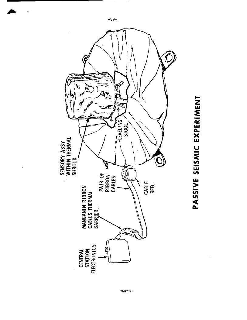
Passive Seismic Experiment (PSE)
The ALSEP Passive Seismic Experiment (PSE) will measure seismic activity of the Moon and obtain information on the physical properties of the lunar crust and interior. The PSE will detect surface tilt produced by tidal deformations, moonquakes and meteorite impacts.
The passive seismometer design and subsequent experiment analysis are the responsibility of Dr.Gary Latham of the Lamont-Doherty Geological Observatory.
A similar passive seismic experiment was deployed as part of the Apollo 12 ALSEP station at Surveyor crater last November and has transmitted Earthward lunar surface seismic activities since that time. The Apollo 12 and 13 seismometers differ from the seismometer left at Tranquility Base in July 1969 by the Apollo 11 crew in that they are continuously powered by a SNAP-27 radioisotope electric generator, while the Apollo 11 seismometer was powered by solar energy and could output data only during the lunar day at its location.
After Lovell and Haise ascend from the lunar surface and rendezvous with the command module in lunar orbit, the lunar module ascent stage will be jettisoned and later ground-commanded to impact on the lunar surface about 42 statute miles from the Apollo 13 landing site at Fra Mauro. Impact of an object of known mass and velocity will assist in cali- brating the Apollo 13 seismometer readouts as well as providing comparative readings between the Apollo 12 and 13 seismometers forming the first two stations of a lunar surface seismic net-work.
-more-
-59-
As,
U
4A XI 4A LU
7) U) 4 0.
EX
PER
IME
NT
-more-

-6o-
There are three major physical components of the PSE:
* The sensor assembly consists of three, long-period seismometers with orthogonally-oriented, capaci-tance type seismic sensors, measuring along two horizontal axes and one vertical axis. This is mounted on a gimbal platform assembly. There is one short period seismometer which has magnet-type sensors. It is located directly on the base of the sensor assembly.
* The leveling stool allows manual leveling of the sen-sor assembly by the astronaut to within +5°, and final leveling to within 3 arc seconds by control motors.
* The thermal shroud covers and helps stabilize the temperature of the sensor assembly. Also, two radio-isotope heaters will protect the instrument from the extreme cold of the lunar night.
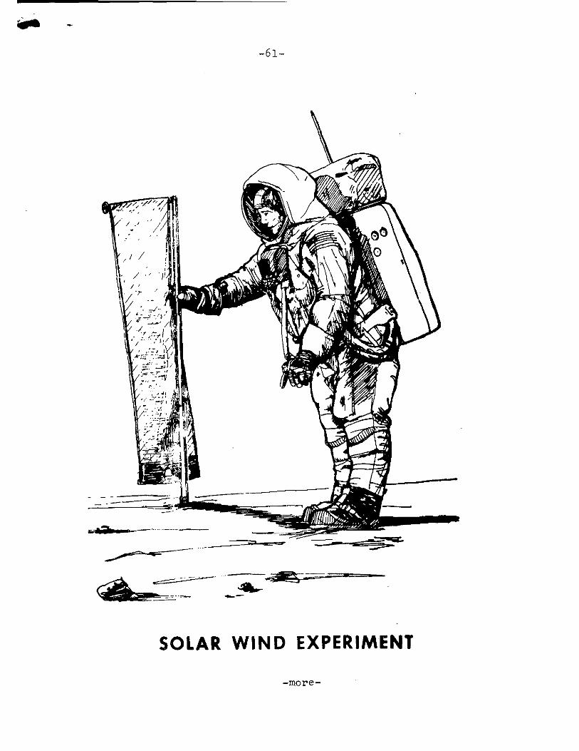
Solar Wind Composition Experiment (SWCE)
The scientific objective of the solar wind composition experiment is to determine the elemental and isotopic com-position of the noble gases in the solar wind. (This is not an ALSEP experiment).
The solar wind composition detector experiment design and subsequent data analysis are the responsibility of J. Geiss and P. Eberhardt, University of Bern (Switzerland) and P. Signer, Swiss Federal Institute of Technology, with Professor Geiss assuming the responsibility of Principal Investigator.
As in Apollo 11 and 12 the SWC detector will be deployed on the Moon and brought back to Earth by the astronauts. The detector, however, will be exposed to the solar wind flux for 20 hours instead of two hours as in Apollo 11 and 18 hours 42 minutes on Apollo 12.
The solar wind composition detector consists of an aluminum foil four square feet in area and about 0.5 mils thick rimmed by Teflon for resistance to tear during deployment. A staff and yard arrangement will be used to deploy the foil and to maintain the foil approximately perpendicular to the solar wind flux. Solar wind particles will penetrate into the foil while cosmic rays will pass right through. The solar wind particles will be firmly trapped at a depth of several hundred atomic layers. After exposure on the lunar surface, the foil is reeled and returned to Earth.
-more-
-61--
SOLAR WIND EXPERIMENT

SOLAR CELLS
DUST DETECTOR SENSOR PACKAGE
CABLE
-62-
Dust Detector
The ALSEP Dust Detector is an engineering measurement designed to detect the presence of dust or debris that may impinge on the ALSEP or accumulate during its operating life.
The measurement apparatus consists of three calibrated solar cells, one pointing in east, west and vertical to face the eliptic path of the Sun. The detector is located on the central station.
Dust accumulation on the surface of the three solar cells will reduce the solar illumination detected by the cells. The temperature of each cell will be measured and compared with predicted values.
DUS7 DETECTOR'
-more -
-63-
Field Geology Investigations
The scientific objectives of the Apollo Field Geology Investigations are to determine the composition of the Moon and the processes which shape its surfaces. This information will help to determine the history of the Moon and its rela-tionship to the Earth. Apollo 11 visited the Sea of Tran-quility (Mare Tranquillitatis) and Apollo 12 studied the Ocean of Storms (Oceanus Procellarum). The results of these studies should help establish the nature of Mare-type areas. Apollo 13 will investigate a hilly upland area.
Geology investigation of the Moon actually began with the telescope. Systematic geology mapping began 10 years ago with a team of scientists at the U.S. Geological Survey. Ranger, Surveyor, and especially Lunar Orbiter data enormously increased the detail and accuracy of these studies. The Apollo 11 and 12 investigations represent another enormous advancement in pro-viding new evidence on the Moon's great age, its curious chemi-stry, the surprisingly high density of the lunar surface material.
On Apollo 13, almost the entire second EVA will be devoted to the Field Geology Investigations and the collection of docu-mental samples. The sample locations will be carefully photo-graphed before and after sampling. The astronauts will care-fully describe the setting from which the sample is collected. In addition to specific tasks, the astronauts will be free to photograph and sample phenomena which they judge to be unusual, significant, and interesting. The astronauts are provided with a package of detailed photo maps which they will use for plan-ning traverses. Photographs will be taken from the LM window. Each feature or family of features will be described, relating to features on the photo maps. Areas and features where photo-graphs should be taken and representative samples collected will be marked on the maps. The crew and their ground support per-sonnel will consider real-time deviation from the nominal plan based upon an on-the-spot analysis of the actual situation. A trench will be dug for soil mechanics investigations.
The Earth-based geologists will be available to advise the astronauts in real-time and will work with the data returned, the photos, the samples of rock and the astronauts' observations to reconstruct here on Earth the astronauts traverse on the Moon.
Each astronaut will carry a Lunar Surface Camera (a modi-fied 70 mm electric Hasselblad). The camera has a 60 mm lens and a Reseau plate. Lens apertures range from 5/5.6 to f/45. Its focus range is from three feet to infinity. A removable polarizing filter is attached to the lens of one of the cameras and can be rotated in 45-degree increments for light polarizing studies.
-more-
-64-
A gnomon, used for metric control of near field (less than 10 feet) stereoscopic photography, will provide angular orientation relative to the local vertical. Information on the distances to objects and on the pitch, roll, and azimuth of the camera's optic axis are thereby included in each photo-graph. The gnomon is a weighted tube suspended vertically on a tripod supported gimbal. The tube extends one foot above the gimbal and is painted with a gray scale in bands one centi-meter wide. Photogrammetric techniques will be used to pro-duce three-dimensional models and maps of the lunar surface from the angular and distance relationship between specific objects recorded on the film.
The 16 mm Data Acquisition Camera will provide times:se-quence coverage from within the LM. It can be operated in several automatic modes, ranging from one frame/second to 24 frames/second. Shutter speeds, which are independent of the frame rates, range from 1/1000 second to 1/60 second. Time exposures are also possible. While a variety of lenses is provided, the 18 mm lens will be used to record most of the geological activities in the one frame/second mode. A similar battery powered 16 mm camera will be carried in EVA.
The Lunar Surface Close-up Camera will be used to obtain very high resolution close-up stereoscopic photographs of the lunar surface to provide fine scale information on lunar soil and rock textures. Up to 100 stereo pairs can be exposed on the preloaded roll of 35 mm color film. The handle grip en-ables the astronaut to operate the camera from a standing posi-tion. The film drive and electronic flash are battery-operated. The camera photographs a 3"x3" area of the lunar surface.
Geological sampling equipment includes tongs, scoop, ham-mer, and core tubes. A 24-inch extension handle is provided for several of the tools to aid the astronaut in using them without kneeling.
Sample return containers (SRC) have been provided for re-turn of up to 40 pounds each of lunar material for Earth-based analysis. The SRC's are identical to the ones used on the Apollo 11 and 12 missions. They are machined from aluminum forgings and are designed to maintain an internal vacuum during the outbound and return flights. The SRC's will be filled with representative samples of lunar surface material, collected and separately bagged by the astronauts on their traverse and docu-mented by verbal descriptions and photography. Subsurface samples will be obtained by using drive tubes 16 inches long and one inch in diameter. A few grams of material will be preserved under lunar vacuum conditions in a special environ-mental sample container.
-more-

-65-
This container will be opened for analysis under vacuum conditions equivalent to that at the lunar surface. Special containers are provided for a magnetic sample and a gas analysis sample.
SNAP-27
SNAP-27 is one of a series of radioisotope thermoelectric generators, or atomic batteries, developed by the U.S. Atomic Energy Commission under its SNAP program. The SNAP (Systems for Nuclear Auxiliary Power) Program is directed at development of generators and reactors for use in space, on land, and in the sea.
SNAP-27 was first used in the Apollo 12 mission to provide electricity for the first Apollo Lunar Surface Experiments Package (ALSEP). A duplicate of the Apollo 12 SNAP-27 will power the Apollo 13 ALSEP.
The basic SNAP-27 unit is designed to produce at least 63 electrical watts of power. It is a cylindrical generator fueled with the radioisotope plutonium 238. It is about 18 inches high and 16 inches in diameter, including the heat radia-ting fins. The generator, making maximum use of the lightweight material beryllium, weighs about 28 pounds unfueled.
The fuel capsule, made of a superalloy material, is 16.5 inches long and 2.5 inches in diameter. It weighs about 15.5 pounds, of which 8.36 pounds represent fuel. The plutonium 238 fuel is fully oxidized and is chemically and biologically inert.
The rugged fuel capsule is contained within a graphite fuel cask from launch through lunar landing. The cask is de-signed to provide reentry heating protection and added contain-ment for the fuel capsule in the unlikely event of an aborted mission. The cylindrical cask with hemispherical ends includes a primary graphite heat shield, a secondary beryllium thermal shield, and a fuel capsule support structure made of titanium and Inconel materials. The cask is 23 inches long and eight inches in diameter and weighs about 24.5 pounds. With the fuel capsule installed, it weighs about 40 pounds. It is mounted on the lunar module descent stage by a titanium support structure.
Once the lunar module is on the Moon, the lunar module pilot will remove the fuel capsule from the cask and insert it into the SNAP-27 generator which will have been placed on the lunar surface near the module.
-more-

-66-
The spontaneous radioactive decay of the plutonium 238 within the fuel capsule generates heat in the generator. An assembly of 442 lead telluride thermoelectric elements con-verts this heat -- 1480 thermal watts -- directly into elec-trical energy -- at least 63 watts. There are no moving parts.
Plutonium 238 is an excellent isotope for use in space nuclear generators. At the end of almost 90 years, plutonium 238 will still supply half of its original heat. In the decay process, plutonium 238 emits mainly the nuclei of helium (alpha radiation), a very mild type of radiation with a short emission range.
Before the use of the SNAP-27 system in the Apollo program was authorized, a thorough review was conducted to assure the health and safety of personnel involved in the mission and the general public. Extensive safety analyses and tests were con-ducted which demonstrated that the fuel would be safely con-tained under almost all credible accident conditions.
Contractors for SNAP-27
General Electric Co., Missile and Space Division, Phila-delphia, Pa., designed, developed, and fabricated the SNAP-27 generator for the ALSEP.
The 3M Co., St. Paul, Minn., fabricated the thermoelectric elements and assembled the SNAP-27 generator.
Solar Division of International Harvester, San Diego, Calif., fabricated the generator's beryllium structure.
Hitco, Gardena, Calif., fabricated the graphite structure for the SNAP-27 Graphite LM Fuel Cask.
Sandia Corp., a subsidiary of Western Electric, operator of AEC's Sandia Laboratory, Albuquerque, N.M., provided tech-nical direction for the SNAP-27 program.
Savannah River Laboratory, Aiken, S.C., operated by the DuPont Co. for the AEC, prepared the raw plutonium fuel.
Mound Laboratory, Miamisburg, Ohio, operated by Monsanto Research Corp., for the AEC, fabricated the raw fuel into the final fuel form and encapsulated the fuel.
-more-

GEN
ERA
TOR

•■•
-68-
PHOTOGRAPHIC EQUIPMENT
Still and motion pictures will be made of most spacecraft maneuvers and crew lunar surface activities, and mapping photos from orbital altitude to aid in plan- ning future landing missions. During lunar surface activities, emphasis will be on photographic documentation of lunar surface features and lunar material sample collection.
Camera equipment stowed in the Apollo 13 command module consists of two 70mm Hasselbiad electric cameras, a 16mm motion picture camera, and the Hycon lunar topographic camera (LTC).
The LTC, to be flown on Apollos 13, 14 and 15, is stowed beneath the commander's couch. In use, the camera mounts in-the crew access hatch window.
The LTC with 18-inch focal length f/4.0 lens provides resolution of objects as small as 15-25 feet from a 60-nm altitude and as small as 3 to 5 feet from the 8-nm.pericynthion. Film format is 4.5-inch square frames on 100 foot long rolls, with a frame rate variable from 4 to 75 frames a minute. Shutter speeds are 1/50, 1/100, and 1/200 second. Spacecraft forward motion during exposures is compensated for by a servo-controlled rocking mount. The film is held flat in the focal plane by a vacuum platen connected to the auxiliary dump valve.
The camera weighs 65 pounds without film, is 28 inches long, 10.5 inches wide, and 12.25 inches high. It is a mod-ification of an aerial reconnaissance camera.
Future lunar landing sites and targets of scientific interest will be photographed with the lunar topographic camera in overlapping sequence of single frame modes. A candidate landing site northwest of the crater Censorinus will be photographed from the 8-mile pericynthion during the period between descent orbit insertion and CSM/LM separation. Additional topographic photos of the Censorinus site and sites near Davy Rille and Descartes will be made later in the mission from the 60-nm circular orbit. The camera again will be unstowed and mounted for 20 minutes of photography of the lunar disc at 5 minute intervals starting at 2 hours after transearth injection.
-more-
-69-
Cameras stowed in the lunar module are two 70mm Hasselblad data cameras fitted with 60mm Zeiss Metric lenses, a 16mm motion picture camera fitted with a lOmm lens, and a Kodak closeup stereo camera for high resolution photos on the lunar surface. The LM Hasselblads have crew chest mounts that leave both hands free.
One of the command module Hasselblad electric cameras is normally fitted with an 80mm f/2.8 Zeiss Planar lens, brut bayonet mount 250mm and 500mm lenses may be substituted for special tasks.
The second Hasselblad camera is fitted with an 80mm lens and a Reseau plate which allows greater dimensional control on photographs of the lunar surface. The 500mm lens will be used only as a backup to the lunar topographic camera.
The 80mm lens has a focussing range from 3 feet to infinity and has a field of view of 38 degrees vertical and horizontal on the square-format film frame. Accessories for the command module Hasselblads include a spotmeter, inter- valometer, remote control cable, and film magazines. Hassel-blad shutter speeds range from time exposure and one second to one 1/500 second.
The Maurer 16mm motion picture camera in the command module has lenses of 5, 18, and 75mm available. The camera weighs 2.8 pounds with a 130-foot film magazine attached. Accessories include a right-angle mirror, a power cable, and a sestant adapter which allows the camera to use the navigation sextant optical system. The LM motion picture camera will be mounted in the right-hand window to record descent and landing and the two EVA periods and later will be taken to the surface.
The 35 mm stereo closeup camera stowed in the. LA MESA shoots 24mm square stereo pairs with an image scale of one-half actual size. The camera is fixed focus and is equipped with a stand-off hood to position the camera at the proper focus distance. A long handle permits an EVA crewman to position the camera without stooping for surface object photography. Detail as small as 40 microns can be recorded. The camera allows photography of significant surface structure which would remain intact only in the lunar environment, such as fine powdery deposits, cracks or holes, and adhesion of particles. A bat-tery-powered electronic flash provides illumination, and film capacity is a minimum of 100 stereo pairs.
-more-

-70-
LUNAR DESCRIPTION
Terrain - Mountainous and crater-pitted, the mountains rising as high as 29 thousand feet and the craters ranging from a few inches to 180 miles in diameter. The craters are thought to be formed primarily by the impact of meteorites. The surface is covered with a layer of fine-grained material resembling silt or sand, as well as small rocks and boulders.
Environment - No air, no wind, and no moisture. The temperature ranges from 243 degrees F. in the two-week lunar day to 279 degrees below zero in the two-week lunar night. Gravity is one-sixth that of Earth. Micrometeoroids pelt the Moon since there is no atmosphere to burn them up. Radiation might present a problem during periods of unusual solar activity.
Far Side - The far or hidden side of the Moon no longer is a complete mystery. It was first photographed by a Russian craft and since then has been photographed many times, particularly from NASA's Lunar Orbiter and Apollo spacecraft.
Origin - There is still no agreement among scientists on the origin of the Moon. The three theories: (1) the Moon once was part of Earth and split off into its own orbit, (2) it evolved as a separate body at the same time as Earth, and (3) it formed elsewhere in space and wandered until it was captured by Earth's gravitational field.
Physical Facts
Diameter
2,160 miles (about 1/4 that of Earth)
Circumference
6,790 miles (about 1/4 that of Earth)
Distance from Earth
238,857 miles (mean; 221,463 minimum to 252,710 maximum)
Surface temperature +243°F (Sun at zenith) -279 °F (night)
Surface gravity 1/6 that of Earth
Mass 1/100th that of Earth
Volume 1/50th that of Earth
Lunar day and night
14 Earth days each
Mean velocity in orbit
2,287 miles-per-hour
Escape velocity 1.48 miles-per-second
Month (period of rotation around Earth) 27 days, 7 hours, 43 minutes
-71-
Landing Site
The landing site selected for Apollo 13 is located at 3° 40' 7"S, 17° 27' 3"W, about 30 miles north of the Fra Mauro crater. The site is in a hilly, upland region. This will be the first Apollo landing to other than a lunar mare, the flat dark areas of the Moon once thought to be lunar seas. This hilly region has been designated as the Fra Mauro formation, a widespread geological unit covering large portions of the lunar surface around Mare Imbrium (Sea of Rains). The Fra Mauro formation is interpreted by lunar geologists to be an ejecta blanket of material thrown out by the event which created the circular Mare Imbrium basin.
The interpretation of the Fra Mauro formation as ejecta from Mare Imbrium gives rise to the expectation that surface material originated from deep within the Moon, perhaps from a hundred miles below the Moon's surface. If the interpretation proves correct, it will also be possible to date the Mare Imbrium event, believed to be a major impact, perhaps the in-fall of a smaller Moon, which was swept up in the primordial, accretionary evolution of the Moon. Based on this theory, rocks from the Fra Mauro formation should predate the rocks returned from either Apollo 11 (4.6 billion years) or Apollo 12 (3.5 billion years) and be close to the original age of the Moon.
-more-
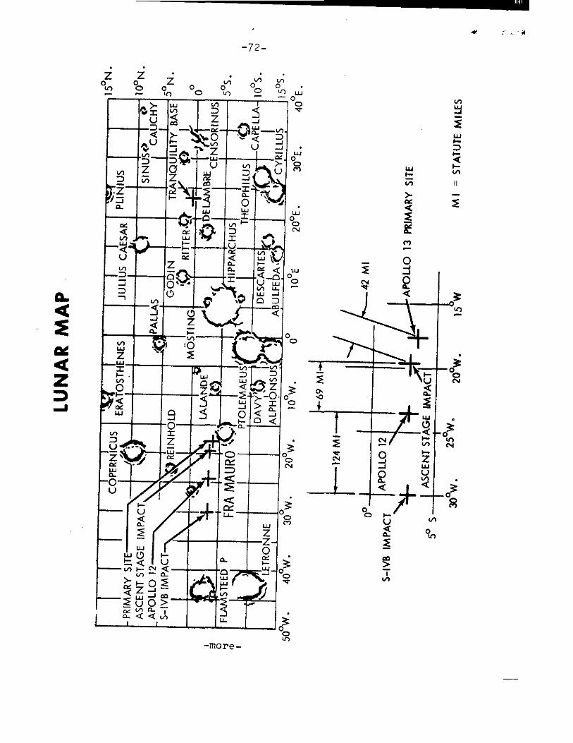
—72—
vi 00
M I
= S
TAT
UT
E M
I LES
PRIM
AR
Y S
ITE
A
PO
LL
O 1
3
LU
NA
R M
AP
—more--
-73-
APOLLO 13 FLAGS, LUNAR MODULE PLAQUE
The United States flag to be erected on the lunar surface measures 30 by 48 inches and will be deployed on a two-piece aluminum tube eight feet long. The folding horizontal bar which keeps the flag standing out from the staff on the airless Moon has been improved over the mech-anisms used on Apollo 11 and 12.
The flag, made of nylon, will be stowed in the lunar module descent stage modularized equipment stowage assembly (MESA) instead of in a thermal-protective tube on the LM front leg, as in Apollo 11 and 12.
.Also carried on the mission and returned to Earth will be 25 United States and 50 individual state flags, each 4 by 6 inches.
A 7 by 9 inch stainless steel plaque, similar to those flown on Apollos 11 and 12, will be fixed to the LM front leg. The plaque has on it the words "Apollo 13" with "Aquarius" beneath, the date, and the signatures of the three crewmen.
-more-
-74-
SATURN V LAUNCH VEHICLE
The Saturn V launch vehicle (SA-508) assigned to the Apollo 13 mission was developed at the Marshall Space Flight Center, Huntsville, Ala. The vehicle is almost identical to those used in the missions of Apollo 8 through 12.
First Stage
The first stage (S-IC) of the Saturn V is built by the Boeing Company at NASA's Michoud Assembly Facility, New Orleans, La. The stage's five F-1 engines develop a total of about 7.6 million pounds of thrust at launch. Major com-ponents of the stage are the forward skirt, oxidizer tank, intertank structure, fuel tank, and thrust structure. Pro-pellant to the five engines normally flows at a rate of 29,364.5 pounds (3,400 gallons) each second. One engine is rigidly mounted on the stage's centerline; the other four engines are mounted on a ring at 90 ° angles around the center engine. These four outer engines are gimbaled to control the vehicle's attitude during flight.
Second Stage
The second stage (S-II) is built by the Space Division of the North American Rockwell Corporation at Seal Beach, Calif. Five J-2 engines develop a total of about 1.16 million pounds of thrust during flight. Major structural components are the forward skirt, liquid hydrogen and liquid oxygen tanks (separated by an insulated common bulkhead), a thrust structure, and an interstage section that connects the first and second stages. The five engines are mounted and used in the same way as the first stage's F-1 engines: four outer engines can be gimbaled; the center one is rigid.
Third Stage
The third stage (S-IVB) is built by the McDonnell Douglas Astronautics Company at Huntington Beach, Calif. Major com-ponents are the aft interstage and skirt, thrust structure, two propellant tanks with a common bulkhead, a forward skirt, and a single J-2 engine. The gimbaled engine has a maximum thrust of 230,000 pounds, and can be shut off and restarted.
-more-
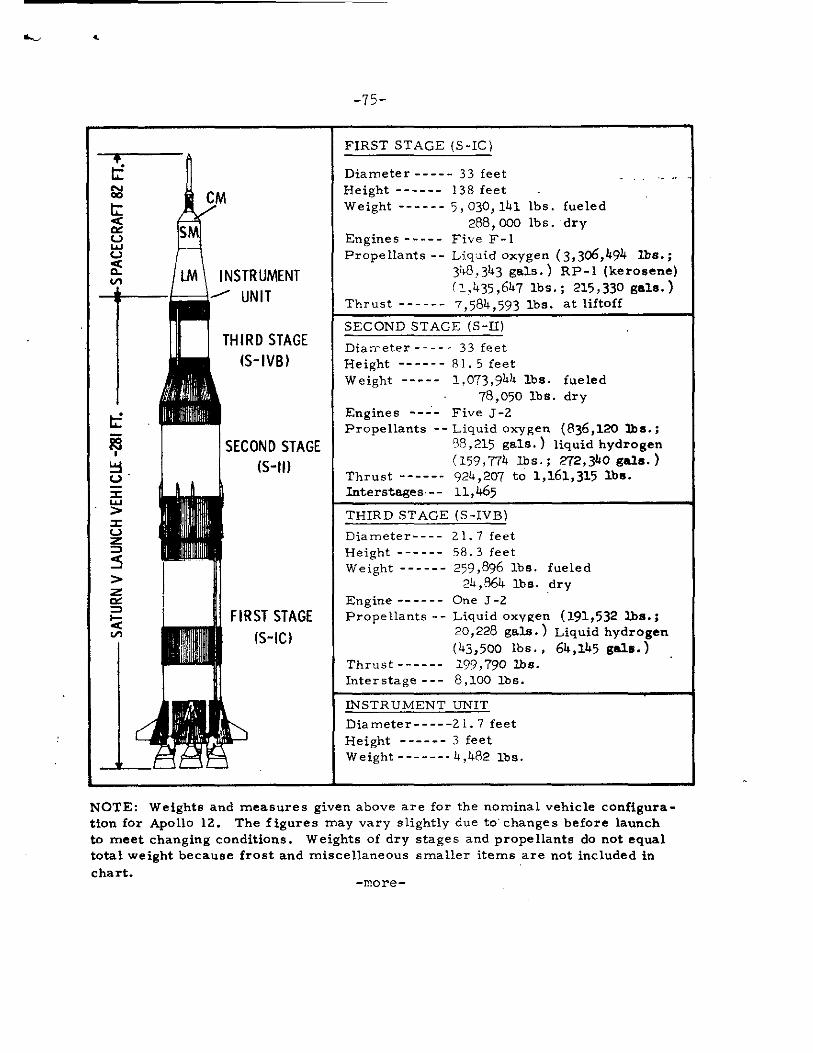
-75-
FIRST STAGE (S-IC)
04 cc L •:C et C-.) La..1 (...) < vs
AIL
• ,-----.
CM
INSTRUMENT
Diameter 33 feet . ..• Height 138 feet - Weight 5, 030, 1141 lbs. fueled
288, 000 lbs. dry Engines Five F-1 Propellants Liquid oxygen (3,306,494 lbs.;
348,343 gals.) RP-1 (kerosene) (1,1435,6147 lbs.; 215,330 gals.)
Thrust 7,584,593 lbs. at liftoff .
'.■"1
C..) E
' >
(...) = 5 > m' w
Q cm
*
iii
,
d
1 ii I
I
-t-1. A
Mk
111
/400111$
h "Fillili
„,111,'
)44 ,\
,1111, ) IP
111111111
1 1111Ill i
it
i#
J. ,I'.
4111 Mk
'
1
11
ii ' T
It” :41I al
UNIT
THIRD STAGE
(S - IVB)
SECOND STAGE (S-11)
i
'
FIRST STAGE (S-IC)
SECOND STAGE (S-II)
Diameter - 33 feet Height 81. 5 feet Weight ----- 1,073,9144 lbs. fueled
- 78,050 lbs. dry Engines ---- Five J-2 Propellants -- Liquid oxygen (836,120 The.;
38,215 gals.) liquid hydrogen ( 159,774 lbs.; 272,340 gals.)
Thrust 9214,207 to 1,3.61,315 lbs. Interstages• 11,465
THIRD STAGE (S-IVB)
Diameter 21. 7 feet Height 58.3 feet Weight 259,896 lbs. fueled
24,864 lbs. dry Engine One 3-2 Propellants Liquid oxygen (191,532 lbs.;
20,228 gals.) Liquid hydrogen (43,500 lbs. , 64,145 gals.) .
Thrust 199,790 lbs. Interstage 8,100 lbs.
INSTRUMENT UNIT
Diameter 21.7 feet Height 3 feet Weight - 4,482 lbs.
NOTE: Weights and measures given above are for the nominal vehicle configura-tion for Apollo 12. The figures may vary slightly due to changes before launch to meet changing conditions. Weights of dry stages and propellants do not equal total weight because frost and miscellaneous smaller items are not included in chart.
-more-
-76-
Instrument Unit
The instrument unit (IU), built by the International Business Machines Corp., at Huntsville, Ala., contains navigation, guidance and control equipment to steer the launch vehicle into its Earth orbit and into translunar trajectory. The six major systems are structural, thermal control, guidance and control, measuring and telemetry, radio frequency, and electric.
The instrument unit provides a path-adaptive guidance scheme wherein a programmed trajectory is used during first stage boost with guidance beginning during second stage burn .
This scheme prevents movements that could cause the vehicle to break up while attempting to compensate for winds or jet streams in the atmosphere.
The instrument unit's inertial platform (heart of the navigation, guidance and control system) provides space-fixed reference coordinates and measures acceleration along three mutually perpendicular axes nr a coordinate system. If the platform fails during boost, systems in the Apollo spacecraft are programmed to provide guidance for the launch vehicle. After second stage ignition, the spacecraft commander could manually steer the vehicle in the event of loss of the launch vehicle inertial platform.
Propulsion
The Saturn V has 37 propulsive units, with thrust ratings ranging from 70 pounds to more than 1.5 million pounds. The large main engines burn liquid propellants; the smaller units use solid or hypergolic propellants.
The five F-1 engines on the first stage burn a combination of RP-1 (kerosene) as fuel and liquid oxygen as oxidizer. Each engine develops approximately 1,516,918 pounds of thrust at liftoff, building to about 1,799,022 pounds before cutoff. The five-engine cluster gives the first stage a thrust range of from 7,584,593 pounds at liftoff to 8,995,108 pounds just before center engine cutoff, The F-1 engine weighs almost 10 tons, is more than 18 feet long and has a nozzle exit diameter of nearly 14 feet. The engine consumes almost three tons of propellant every second.
The first stage also has eight solid-fuel retrorockets that fire to separate the first and second stages, Each retro-rocket produces a thrust of 87,900 pounds for 0.6 seconds.
more-

-77-
The second and third stages are powered by J-2 engines that burn liquid hydrogen (fuel) and liquid oxygen (oxidizer). J-2 engine thrust varies from 184,841 to 232,263 pounds during flight. The 3,500-pound J-2 engine is considered more efficient than the F-1 engine because the J-2 burns high-energy liquid hydrogen. F-1 and J-2 engines are built by the Rocketdyne Division of the North American Rockwell Corp.
The second stage also has four 21,000-pound-thrust solid fuel ullage rockets that settle liquid propellant in the bottom of the main tanks and help attain a "clean" separation from the first stage. Four retrorockets, located in the S-IVB's aft interstage (which never separates from the S-II), separate the S-II from the S-IVB. There are two jettisonable ullage rockets for propellant settling before engine ignition. Eight smaller engines in the two auxiliary propulsion system modules on the S-IVB stage provide three-axis attitude control.
-more-

-78--
COMMAND AND SERVICE MODULE STRUCTURE, SYSTEMS
The Apollo spacecraft for the Apollo 13 mission is comprised of Command Module 109, Service Module 109, Lunar Module 7, a spacecraft-lunar module adapter (SLA) and . a launch escape system. The SLA houses the lunar module and serves as a mating structure between the Saturn V instrument unit and the SM.
Launch Escape System (LES) -- Would propel command module to safety in an aborted launch. It has three solid-propellant rocket motors: a 147,000 pound-thrust launch escape system motor, a 2,400-pound-thrust pitch control motor, and a 31,500 pound-thrust tower jettison motor. Two canard vanes deploy to turn the command module aerodynamically to an attitude with the heat-shield forward. The system is 33 feet tall and 4 feet, in diameter at the base, and weighs 8,945 pounds.
Command Module (CM) Structure -- The command module is a pressure. vessel encased in heat shields, cone-shaped, weighing 12,365 pounds at launch.
The command module consists of a forward compartment which contains two reaction control engines and components of the Earth landing system; the crew compartment or inner pressure vessel containing crew accomodations, controls and displays, and many of the spacecraft systems; and the aft compartment housing ten reaction control engines, propellant tankage, helium tanks, water tanks, and the CSM umbilical cable. The crew compartment contains 210 cubic feet of habitable volume.
Heat-shields around the three compartments are made of brazed stainless steel honeycomb with an outer layer of phenolic epoxy resin as an ablative material.
CSM and LM are equipped with the probe-and-drogue _ docking hardware. The probe assembly is a powered folding coupling and impact attentuating device mounted in the CM tunnel that mates with a conical drogue mounted in the LM docking tunnel. After the 12 automatic docking latches are checked following a docking maneuver, both the probe and drogue are removed to allow crew transfer between the CSM and LM.
Service Module (SM) Structure -- At launch, the service module for the Apollo 13 mission will weigh 51,105 pounds. Aluminum honeycomb panels one inch thick form the outer skin, and milled aluminum radial beams separate the interior into six sections around a central cylinder containing two helium spheres, four sections containing service propulsion system fuel-oxidizer tankage, another containing fuel cells, cryogenic oxygen and hydrogen, and one sector essentially empty.
-more-
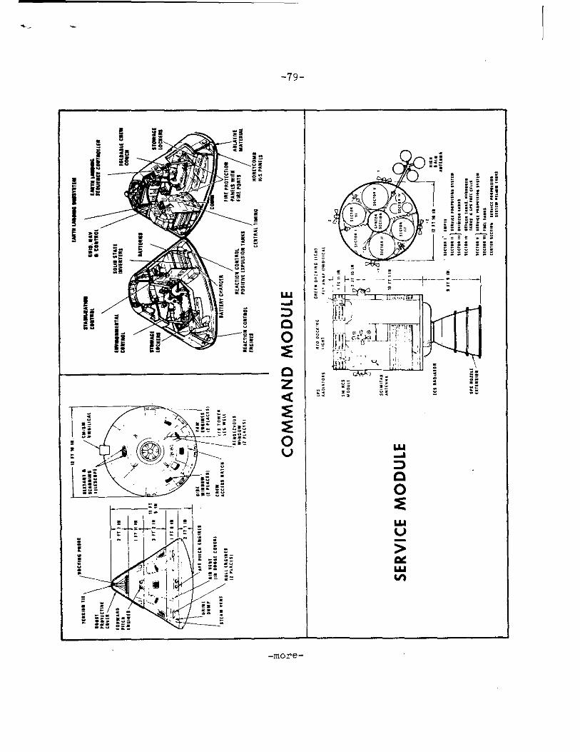
-79-
W
-I
D
0
0
CO
MM
AN
D
-more-

LUNA
R M
ODU
L E
CO
MM
AND
MO
DUL E
0 —J -01 0 a. <
DO
CK
ING
ME
CH
AN
ISM
S
-more -
Spacecraft-LM Adapter (SLA) Structure -- The spacecraft LM adapter is a truncated cone 28 feet long tapering from 260 inches diameter at the base to 154 inches at the forward end at the service module mating line. The SLA weighs 4,000 pounds and houses the LM during launch and Earth orbital flight.
CSM Systems
Guidance, Navigation and Control System (GNCS) -- Measures and controls spacecraft position, attitude, and velocity, calculates trajectory, controls spacecraft propulsion system thrust vector, and displays abort data. The guidance system consists of three subsystems: Inertial, made up of an inertial measurement unit and associated power and data components; computer which processes information to or from other components; and optics consisting of scanning telescope and sextant for celestial and/or landmark sighting for spacecraft navigation. VHF ranging device serves as a backup to the LM rendezvous radar.
Stabilization and Control Systems (SCS) -- Controls space-craft rotation, translation, and thrust vector and provides displays for crew-initiated maneuvers; backs up the guidance system for control functions. It has three subsystems; attitude reference, attitude control, and thrust vector control.
Service Propulsion System (SPS) -- Provides thrust for large spacecraft velocity changes through a gimbal-mounted 20,500-pound-thrust hypergolic engine. using a nitrogen tetroxide oxidizer and a 50-50 mixture of unsymmetrical dimethyl hydrazine and hydrazine fuel. This system is in the service module. The system responds to automatic firing commands from the guidance and navigation system or to manual commands from the crew. The engine thrust level is not throttleable. The stabilization and control system gimbals the engine to direct the thrust vector through the spacecraft center of gravity.
Telecommunications System -- Provides voice, television,' telemetry, and command data and tracking and ranging between the spacecraft and Earth, between the command module and the lunar module and between the spacecraft and astronauts during EVA. It also provides intercommunications between astronauts.
The high-gain steerable S-Band antenna consists of four, 31-inch-diameter parabolic dishes mounted on a folding boom at the aft end of the service module. Signals from the ground stations can be tracked either automatically or manually with the antenna's gimballing system. Normal S-Band voice and uplink/downlink communications will be handled by the omni and high-gain antennas.
-82-
Sequential System -- Interfaces with other spacecraft systems and subsystems to initiate time critical functions during launch, docking maneuvers, sub-orbital aborts, and entry portions of a mission. The system also controls routine spacecraft sequencing such as service module separation and deployment of the E arth landing system.
Emergency Detection System (EDS) -- Detects and displays to the crew launch vehicle emergency conditions, such as excessive pitch or roll rates or two engines out, and automatically or manually shuts down the booster and activates the launch escape system; functions until the spacecraft is in orbit.
Earth Landing System (ELS) -- Includes the drogue and main parachute system as well as post-landing recovery aids. In a normal entry descent, the command module forward heat shield is jettisoned at 24,000 feet, permitting mortar deployment of two reefed 16.5-foot diameter drogue parachutes for orienting and decelerating the spacecraft. After disreef and drogue release, three mortar deployed pilot chutes pull out the three main 83.3-foot diameter parachutes with two-stage reefing to provide gradual inflation in three steps. Two main parachutes out of three can provide a safe landing.
heaction Control System (RCS) -- The SM RCS has four identical RCS "quads" mounted around the SM 90 degrees apart. Each quad has four 100 pound-thrust engines, two fuel and two oxidizer tanks and a helium pressurization sphere. Attitude control and small velocity maneuvers are made with the SM RCS.
The CM RCS consists of two independent six-engine subsystems of six 93 pound-thrust engines each used for spacecraft attitude control during entry. Propellants for both CM and SM RCS are monomethyl hydrazine fuel and nitrogen tetroxide oxidizer with helium pressurization. These propellants burn spontaneously when combined (without an igniter).
Electrical Power System (EPS) -- Provides electrical energy sources, power generation and control, power conversion, conditioning, and distribution to the spacecraft. The primary source of electrical power is the fuel cells mounted in the SM. The fuel cell also furnishes drinking water to the astronauts as a by-product.
-more-
-83-
Three silver-zinc oxide storage batteries supply power to the CM during entry and after landing, provide power for sequence controllers, and supplement the fuel cells during periods of peak power demand. A battery charger assures a full charge prior to entry.
Two other silver-zinc oxide batteries supply power for explosive devices for CM/SM separation, parachute deployment and separation, third-stage separation, launch escape tower separation, and other pyrotechnic uses.
Environmental Control System (ECS) -- Controls spacecraft atmosphere, pressure, and temperature and manages water. In addition to regulating cabin and suit gas pressure, temperature and humidity, the system removes carbon dioxide, odors and particles and ventilates the cabin after landing. It collects and stores fuel cell potable water for crew use, supplies water to the glycol evaporators for cooling, and dumps surplus water overboard through the waste H 00 dump nozzle. Proper operating temperature of electronics ana electrical equipment is maintained by this system through the use of the cabin heat exchangers, the space radiators, and the glycol evaporators.
Recovery Aids -- Recovery aids include the uprighting system, swimmer interphone connections, sea dye marker, flash-ing beacon, VHF recovery beacon, and VHF transceiver. The up-righting system consists of three compressor-inflated bags to upright the spacecraft if it should land in the water apex down (stable II position).
Caution and Warning System -- Monitors spacecraft systems for out-of-tolerance conditions and alerts crew by visual and audible alarms.
Controls and Displays -- Provide status readouts and control functions of spacecraft systems in the command and service modules. All controls are designed to be operated by crewmen in pressurized suits. Displays are grouped by system and located according to the frequency of use and crew responsibility.

-84-
LUNAR MODULE STRUCTURES, WEIGHT
The lunar module is a two—stage vehicle designed for space operations near and on the Moon. The lunar module stands 22 feet 11 inches high and is 31 feet wide (diagonally across landing gear). The ascent and descent stages of the LM operate as a unit until staging, when the ascent stage functions as a single spacecraft for rendezvous and docking with the CM.
Ascent Stage
Three main sections make up the ascent stage: the crew compartment, midsection, and aft equipment bay. Only the crew compartment and midsection are pressurized (4.8 psig). The cabin volume is 235 cubic feet (6.7 cubic meters). The stage measures 12 feet 4 inches high by 14 feet 1 inch in diameter. The ascent stage has six substructural areas: crew compartment, midsection, aft equipment bay, thrust chamber assembly cluster supports, antenna supports, and thermal and micrometeoroid shield.
The cylindrical crew compartment is 92 inches (2.35 m) in diameter and 42 inches (1.07 m) deep. Two flight stations are equipped with control and display panels, armrests, body restraints, landing aids, two front windows, an overhead docking window, and an alignment optical telescope in the center between the two flight stations. The habitable volume is 160 cubic feet.
A tunnel ring atop the ascent stage meshes with the command module docking latch assemblies. During docking, the CM docking ring and latches are aligned by the LM drogue and the CSM probe.
The docking tunnel extends downward into the midsection 16 inches (40 cm). The tunnel is 32 inches (81 cm) in diameter and is used for crew transfer between the CSM and LM. The upper hatch on the inboard end of the docking tunnel opens inward and cannot be opened without equalizing pressure on both hatch surfaces.
A thermal and micrometeoroid shield of multiple layers of Mylar and a single thickness of thin aluminum skin encases the entire ascent stage structure.
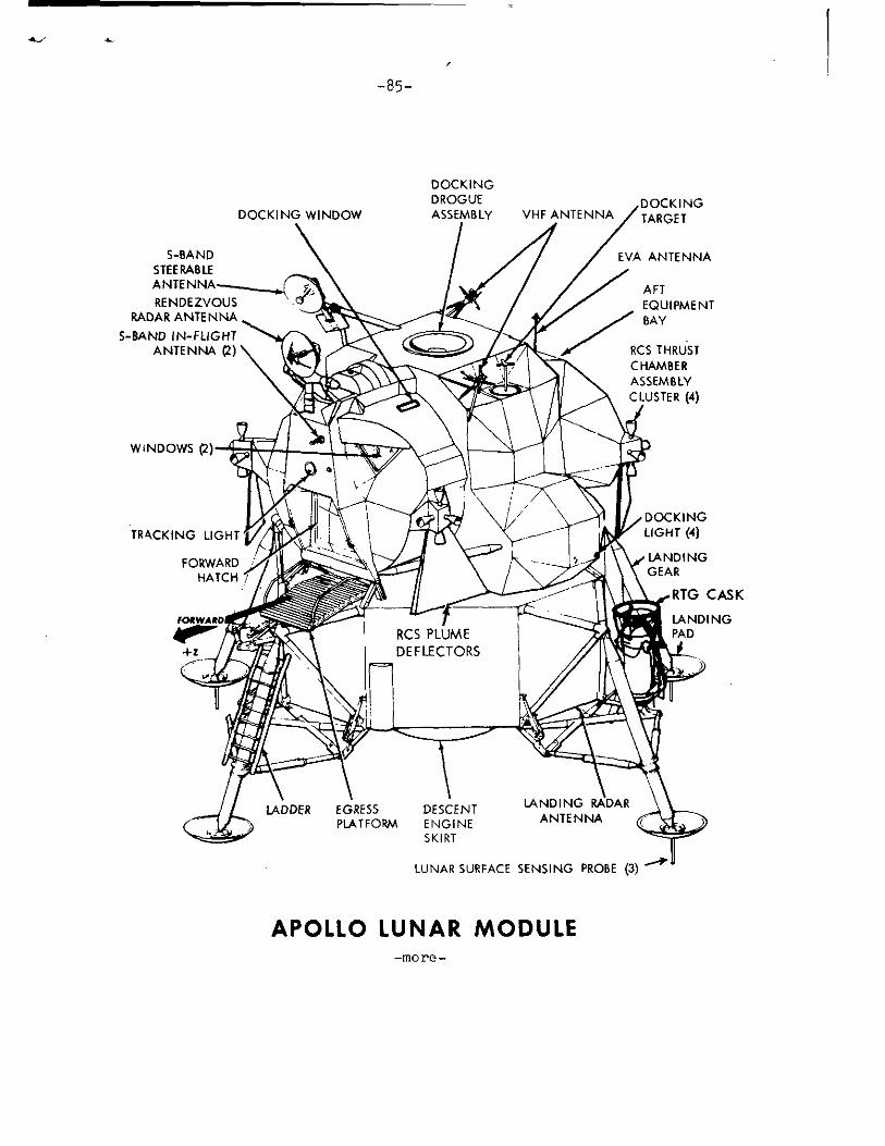
-85-
DOCKING TARGET
.
S-BAND
1
EVA ANTENNA STEERABLE ANTENNA---___
RENDEZVOUS EQUIPMENT
_4.j\ AFT
S-BAND IN-FLIGHT
RADAR ANTENNA „
flpkt 1100 aivrAt
BAY
ANTENNA (2)
4 11Pr VII
l
-411011 100
11*
aeVai
1
AI I ...
..."...#7". RCS THRUST C HAMBER ASSEMBLY CLUSTER (4)
DOCKING LIGHT (4)
DOCKING DROGUE
DOCKING WINDOW
ASSEMBLY
LANDING GEAR
FORWARD HATCH
FORWARD
+Z
LADDER EGRESS DESCENT PLATFORM ENGINE
SKIRT
LANDING RADAR ANTENNA
APOLLO LUNAR MODULE -more -
-86-
Descent Stage
The descent stage center compartment houses the descent engine, and descent propellant tanks are housed in the four square bays around the engine. Quadrant II (Seq bay) contains ALSEP, and Radioisotope Thermoelectric Generator KRTG) externally. Quadrant IV contains the MESA. The descent stage measures 10 feet 7 inches high by 14 feet 1 inch in diameter and is encased in the Mylar and aluminum alloy thermal and micrometeoroid shield.
The LM egress platform, or "porch", is mounted on the forward outrigger just below the forward hatch. A ladder extends down the forward landing gear strut from the porch for crew lunar surface operations.
The landing gear struts are explosively extended and provide lunar surface landing impact attenuation. The main struts are filled with crushable aluminum honeycomb for absorbing compression loads. Footpads 37 inches (0.95 m) in diameter at the end of each landing gear provide vehicle support on the lunar surface.
Each pad (except forward pad) is fitted with a 68 inch long lunar surface sensing probe which signals the crew to shut down the descent engine upon contact with the lunar surface.
LM-7 flown on the Apollo 13 mission has a launch weight of 33,476 pounds. The weight breakdown is as follows:
Ascent stage, dry 4,668 lbs. Includes water and oxygen; no
Descent stage, dry 4,650 lbs. crew
RCS propellants (loaded) 590 lbs.
DPS propellants (loaded) 18,339 lbs.
APS propellants (loaded) 5,229 lbs.
33,476 lbs.
Lunar Module Systems
Electrical Power System -- The LM DC electrical system consists of six silver zinc primary batteries -- four in the descent stage and two in the ascent stage. Twenty-eight-volt DC power is distributed to all LM systems. AC power (117v 400 Hz) is supplied by two inverters.
-more-
-87-
Environmental Control System -- Consists of the atmosphere revitalization section, oxygen supply and cabin pressure control section, water management, heat transport section, and outlets for oxygen and water reservicing of the portable life support system (PLSS).
Components of the atmosphere revitalization section are the suit circuit assembly which cools and ventilates the pressure garments, reduces carbon dioxide levels, removes odors, noxious gases and excessive moisture; the cabin recirculation assembly which ventilates and controls cabin atmosphere temperatures; and the steam flex duct which vents to space steam from the suit circuit water evaporator.
The oxygen supply and cabin pressure section supplies gaseous oxygen to the atmosphere revitalization section for maintaining suit and cabin pressure. The descent stage oxygen supply provides descent flight phase and lunar stay oxygen needs, and the ascent stage oxygen supply provides oxygen needs for the ascent and rendezvous flight phase.
Water for drinking, cooling, fire fighting, food preparation, and refilling the PLSS cooling water servicing tank is supplied by the water management section. The water is contained in three nitrogen-pressurized bladder-type tanks, one of 367-pound capacity in the descent stage and two of 47.5-pound capacity in the ascent stage.
The heat transport section has primary and secondary water-glycol solution coolant loops. The primary coolant loop circulates water-glycol for temperature control of cabin and suit circuit oxygen and for thermal control of batteries and electronic compon-ents mounted on cold - plates and rails. If the primary loop becomes inoperative, the secondary loop circulates coolant through the rails and cold plates only. Suit circuit cooling during secondary coolant loop operation is provided by the suit loop water boiler. Waste heat from both loops is vented overboard by water evaporation or sublimators.
Communications System -- Two S-band transmitter-receivers, two VHF transmitter-receivers, a signal processing assembly, and associated spacecraft antenna make up the LM communications system. The system transmits and receives voice and tracking and ranging data, and transmits telemetry data on about 270 measure-ments and TV signals to the ground. Voice communications between the LM and ground stations is by S-band, and between the LM and CSM voice is on VHF.
-more-

-88-
Although no real-time commands can be sent to the LM, the digital uplink processes guidance officer commands, such as state vector updates, transmitted from Mission Control Center to the LM guidance computer.
The data storage electronics assembly (DSEA) is a four-channel voice recorder with timing signals, with a 10-hour recording capacity, which will be brought back into the CSM for return to Earth. DSEA recordings cannot be "dumped" to ground stations.
LM antennas are one 26-inch-diameter parabolic S-band steerable antenna, two S-band inflight antennas, two VHF in-flight antennas, EVA antenna, and an erectable S-band antenna (optional) for lunar surface.
Guidance, Navigation, and Control System -- Comprised of six sections: primary guidance and navigation section (PGNS), abort guidance section (AGS), radar section, control electron-ics section (CES), and orbit rate display Earth and lunai ,
(ORDEAL).
* The PGNS is an aided inertial guidance system updated by the alignment optical telescope, an inertial measurement unit, and the rendezvous and landing radars. The system pro-vides inertial reference data for computations, produces in-ertial alignment reference by feeding optical sighting data into the LM guidance computer, displays position and velocity data, computes LM-CSM rendezvous data from radar inputs, controls attitude and thrust to maintain desired LM trajectory, and controls descent engine throttling and gimbaling.
The LM-7 primary guidance computer has the Luminary 1C Software program, which is an improved version over that in LM-6.
* The AGS is an independent backup system for the PGNS, having its own inertial sensors and computer.
* The radar section is made up of the rendezvous radar which provides CSM range and range rate, and line-of-sight angles for maneuver computation to the LM guidance computer; and the landing radar which provides altitude and velocity data to the LM guidance computer during lunar landing. The rendezvous radar has an operating range from 80 feet to 400 nautical miles. The ranging tone transfer assembly, utilizing VHF electronics, is a passive responder to the CSM VHF ranging device and is a backup to the rendezvous radar.
-more-

-89-
* The CES controls LM attitude and translation about all axes. It also controls by PGNS command the automatic operation of the ascent and descent engine and the reaction control thrusters. Manual attitude controller and thrust-translation controller commands are also handled by the CES.
*ORDEAL, displayed on the flight director attitude indicator, is the computed local vertical in the pitch axis during circular Earth or lunar orbits.
Reaction Control System -- The LM has four RCS engine clusters of four 100-pound (45.4 kg) thrust engines each, which use helium-pressurized hypergolic propellants. The oxidizer is nitrogen tetroxide, fuel is Aerozine 50 (50/50 blend of hydrazine and unsymmetrical dimethyl hydrazine). Interconnect valves permit the RCS system to draw from ascent engine propellant tanks.
The RCS provides small stabilizing impulses during ascent and descent burns, controls LM attitude during maneuvers, and produces thrust for separation, and for ascent/descent engine tank ullage. The system may be operated in either the pulse or steady-state modes.
Descent Propulsion System -- Maximum rated thrust of the descent engine is 9,870 pounds (4,380.9 kg) and is throttleable between 1,050 pounds (476.7 kg) and 6,300 pounds (2,860.2 kg). The engine can be gimbaled six degrees in any direction in response to attitude commands and to compensate for center of gravity offsets. Propellants are helium-pressurized Aerozine 50 and nitrogen tetroxide.
Ascent Propulsion System -- The 3,500-pound (1,589 kg) thrust ascent engine is not gimbaled and performs at full thrust. The engine remains dormant until after the ascent stage is separated from the descent stage. Propellants are the same as are burned by the RCS engines and the descent engine.
Caution and 'Warning, Controls and Displays -- These two systems have the same function aboard the lunar module as they do aboard the command module (See CSM systems section.)
Tracking and Docking Lights -- A flashing tracking light (once per second, 20 milliseconds duration) on the front face of the lunar module is an aid for contingency CSM-active rendezvous LM rescue. Visibility ranges from 400 nautical miles through the CSM sextant to 130 miles with the naked eye. Five docking lights analagous to aircraft running lights are mounted on the LM for CSM-active rendezvous: two forward yellow lights, aft white light, port red light and starboard green light. All docking lights have about a 1,000-foot visibility.
-more-
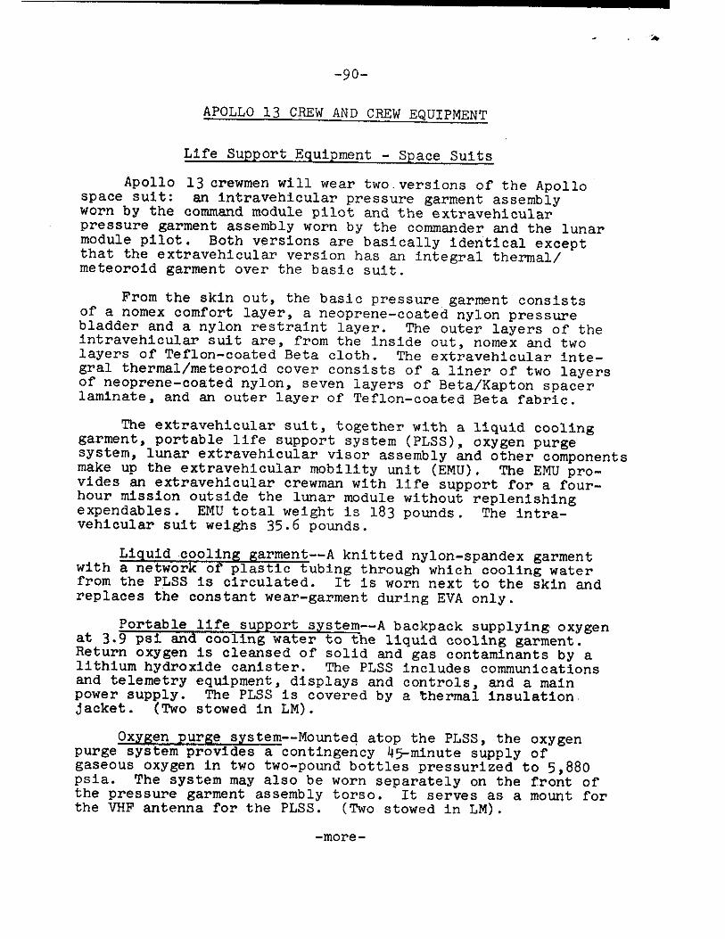
-90-
APOLLO 13 CREW AND CREW EQUIPMENT
Life Support Equipment - Space Suits
Apollo 13 crewmen will wear two. versions of the Apollo space suit: an intravehicular pressure garment assembly worn by the command module pilot and the extravehicular pressure garment assembly worn by the commander and the lunar module pilot. Both versions are basically identical except that the extravehicular version has an integral thermal/ meteoroid garment over the basic suit.
From the skin out, the basic pressure garment consists of a nomex comfort layer, a neoprene-coated nylon pressure bladder and a nylon restraint layer. The outer layers of the intravehicular suit are, from the inside out, nomex and two layers of Teflon-coated Beta cloth. The extravehicular inte- gral thermal/meteoroid cover consists of a liner of two layers of neoprene-coated nylon, seven layers of Beta/Kapton spacer laminate, and an outer layer of Teflon-coated Beta fabric.
The extravehicular suit, together with a liquid cooling garment, portable life support system (PLSS), oxygen purge system, lunar extravehicular visor assembly and other components make up the extravehicular mobility unit (EMU). The EMU pro-vides an extravehicular crewman with life support for a four-hour mission outside the lunar module without replenishing expendables. EMU total weight is 183 pounds. The intra-vehicular suit weighs 35.6 pounds.
Liquid coolin& Karment--A knitted nylon-spandex garment with a network of plastic tubing through which cooling water from the PLSS is circulated. It is worn next to the skin and replaces the constant wear-garment during EVA only.
Portable life support system--A backpack supplying oxygen at 3.9 psi and cooling water to the liquid cooling garment. Return oxygen is cleansed of solid and gas contaminants by a lithium hydroxide canister. The PLSS includes communications and telemetry equipment, displays and controls, and a main power supply. The PLSS is covered by a thermal insulation. jacket. (Two stowed in LM).
Oxygen purge system--Mounted atop the PLSS, the oxygen purge system provides a contingency 45-minute supply of gaseous oxygen in two two-pound bottles pressurized to 5,880 psis. The system may also be worn separately on the front of the pressure garment assembly torso. It serves as a mount for the VHF antenna for the PLSS. (Two stowed in LM).
-more-
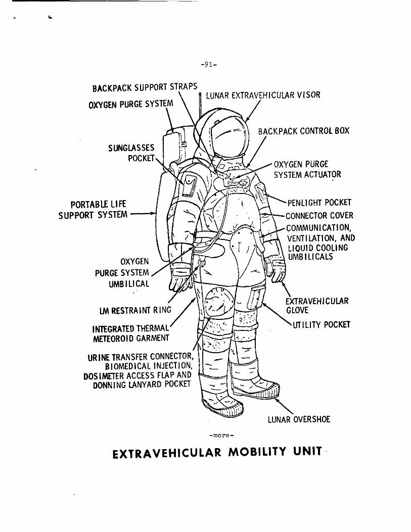
-91-
BACKPACK SUPPORT STRAPS
OXYGEN PURGE SYSTEM LUNAR EXTRAVEH ICULAR VISOR
BACKPACK CONTROL BOX
SUNGLASSES POCKET
OXYGEN PURGE SYSTEM ACTUATOR
PORTABLE LIFE SUPPORT SYSTEM
OXYGEN PURGE SYSTEM
UMB I LI CAL
PENLIGHT POCKET CONNECTOR COVER COMMUN 1 CAT I ON, VENTILATION, AND LIQUID COOLING UMB I LI CA LS
LM RESTRAINT RING EXTRAVEHICULAR
INTEGRATED THERMAL METEOROID GARMENT
GLOVE
UTILITY POCKET
URINE TRANSFER CONNECTOR, B I OMED I CA L INJECTION,
DOSIMETER ACCESS FLAP AND DONNING LANYARD POCKET
LUNAR OVERSHOE
-more -
EXTRAVEHICULAR MOBILITY UNIT
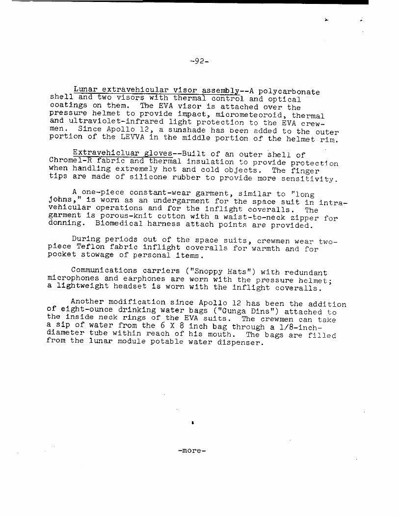
-92--
Lunar extravehicular visor assembly--A polycarbonate shell and two visors with thermal control and optical coatings on them. The EVA visor is attached over the pressure helmet to provide impact, micrometeoroid, thermal and ultraviolet-infrared light protection to the EVA crew-men. Since Apollo 12, a sunshade has been added to the outer portion of the LEVVA in the middle portion of the helmet rim.
Extravehicluar gloves--Built of an outer shell of Chromel-R fabric and thermal insulation to provide protection when handling extremely hot and cold objects. The finger tips are made of silicone rubber to provide more sensitivity.
A one-piece constant-wear garment, similar to "long johns," is worn as an undergarment for the space suit in intra-vehicular operations and for the inflight coveralls. The garment is porous-knit cotton with a waist-to-neck zipper for donning. Biomedical harness attach points are provided.
During periods out of the space suits, crewmen wear two-piece Teflon fabric inflight coveralls for warmth and for pocket stowage of personal items.
Communications carriers ("Snappy Hats") with redundant microphones and earphones are worn with the pressure helmet; a lightweight headset is worn with the inflight coveralls.
Another modification since Apollo 12 has been the addition of eight-ounce drinking water bags ("Gunga Dins") attached to the inside neck rings of the EVA suits. The crewmen can take a sip of water from the 6 X 8 inch bag through a 1/8-inch-diameter tube within reach of his mouth. The bags are filled from the lunar module potable water dispenser.
-more-
1
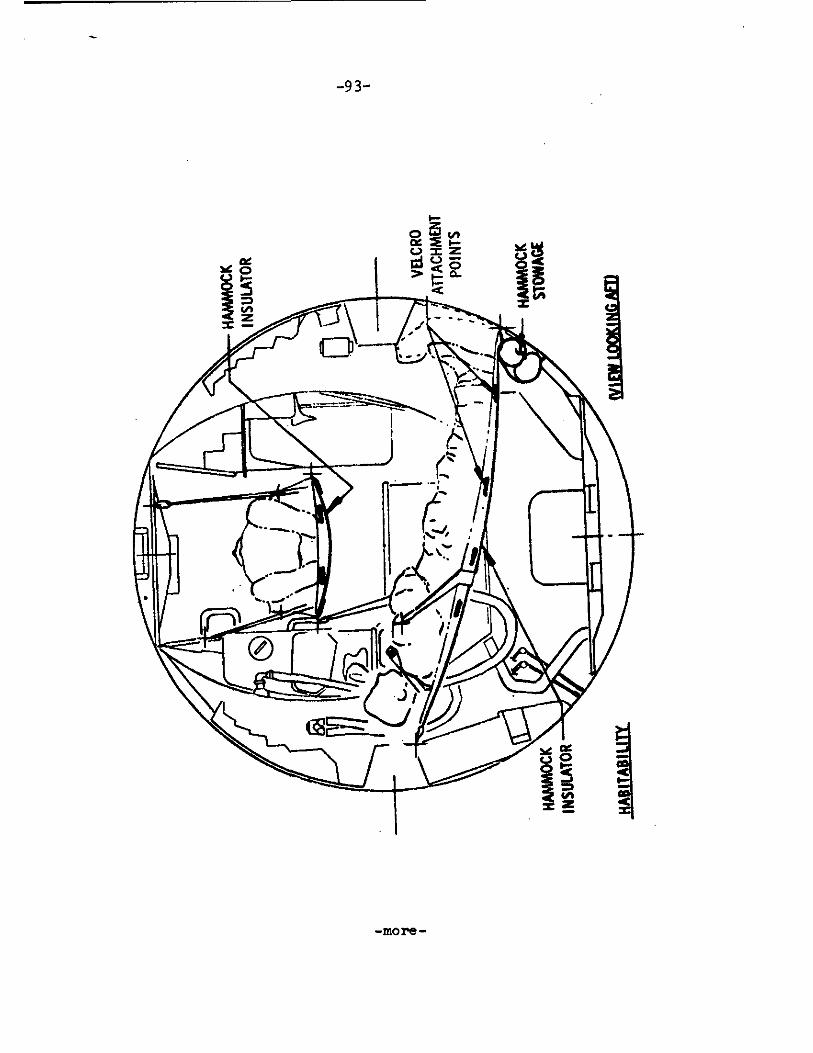
-9 3-
-more-
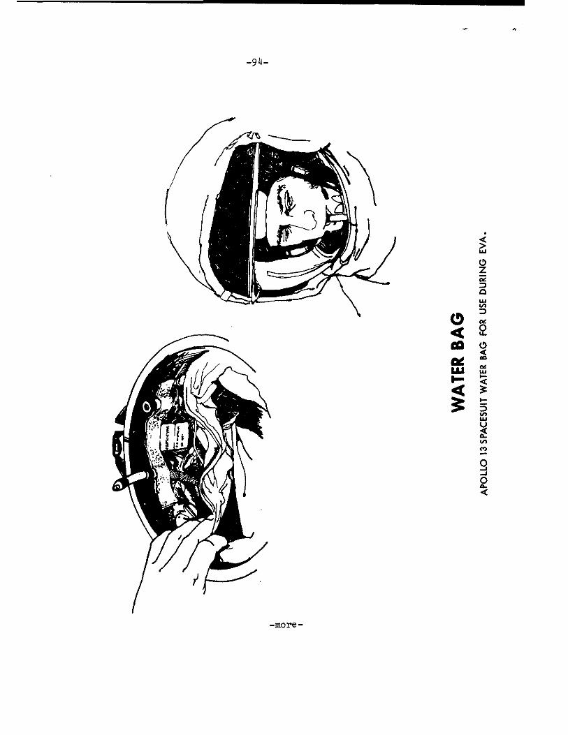
-94-
WA
TER
BA
G
AP
OL
LO
13 S
PAC
ESU
IT W
ATE
R BA
G F
OR
USE
DU
RIN
G E
VA
.
-more-
-95-
Apollo Lunar Hand Tools
Special Environmental Container - The special environ-mental sample is collected in a carefully selected area and sealed in a special container which will retain a high vacuum. The container is opened in the Lunar Receiving Laboratory where it will provide scientists the opportunity to study lunar material in its original environment.
Extension handle - This tool is of aluminum alloy tubing with a malleable stainless steel cap designed to be used as an anvil surface. The handle is designed to be used as an extension for several other tools and to permit their use without re-quiring the astronaut to kneel or bend down. The handle is approximately 24 inches long and 1 inch in diameter. The handle contains the female half of a quick disconnect fitting designed to resist compression, tension, torsion, or a combina-tion of these loads.
Three core tubes - These tubes are designed to be driven or augered into loose gravel, sandy material, or into soft rock such as feather rock or pumice. They are about 15 inches in length and one inch in diameter and are made of aluminum tubing. Each tube is supplied with a removeable non-serrated cutting edge and a screw-on cap incorporating a metal-to-metal crush seal which replaces the cutting edge. The upper end of each tube is sealed and designed to be used with the extension handle or as an anvil. Incorporated into each tube is a spring device to retain loose materials in the tube.
Scoops (large and small) - These tools are designed for use as a trowel and as a chisel. The scoop is fabricated primarily of aluminum with a hardened-steel cutting edge riveted on and a nine-inch handle. A malleable stainless steel anvil is on the end of the handle. The angle between the scoop pan and the handle allows a compromise for the dual use. The scoop is used either by itself or with the extension handle. The large scoop has a seive which permits particles smaller than 1/2 cm to pass through.
Sampling hammer - This tool serves three functions, as a sampling hammer, as a pick or mattock, and as a hammer to drive the core tubes or scoop. The head has a small hammer face on one end, a broad horizontal blade on the other, and large hammering flats on the sides. The handle is 14 inches long and is made.of formed tubular aluminum. The hammer has on its lower end a quick-disconnect to allow attachment to the exten-sion handle for use as a hoe. The head weight has been in-creased to provide more impact force.
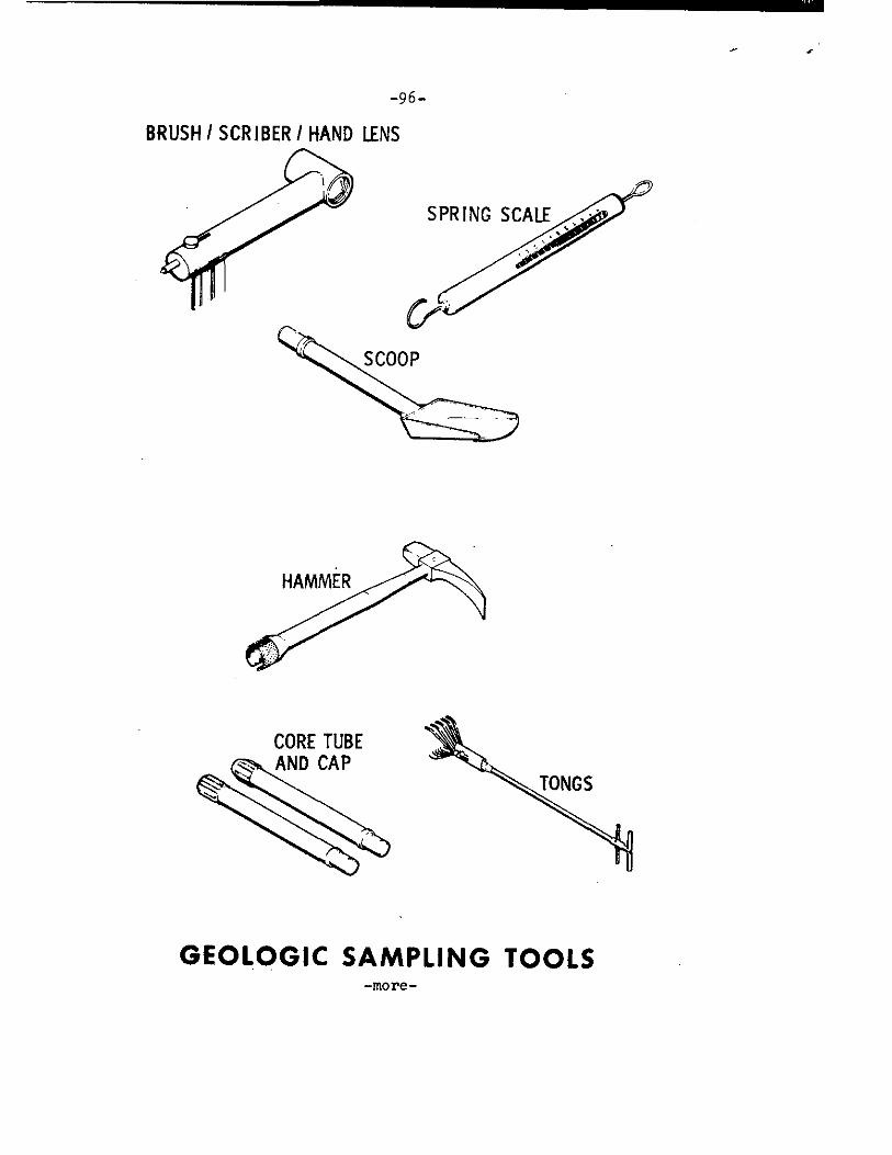
SPRING SCALE
CORE TUBE AND CAP
-96-
BRUSH I SCRIBER I HAND LENS
GEOLOGIC SAMPLING TOOLS -more-
-97-
Tongs - The tongs are designed to allow the astronaut to retrieve small samples from the lunar surface while in a standing position. The tines are of such angles, length, and number to allow samples of from 3/8 up to 2-1/2-inch diameter to be picked up. This tool is 24 inches in overall length.
Brush/Scriber/Hand Lens - A composite tool
(1) Brush - To clean samples prior to selection (2) Scriber - To scratch samples for selection and to
mark for identification (3) Hand lens - Magnifying glass to facilitate sample
selection
Spring Scale - To weigh two rock boxes and other bags containing lunar material samples, to maintain weight budget for return to Earth.
Instrument staff - The staff hold the Hasselblad camera. The staff breaks down into sections. The upper section telescopes to allow generation of a vertical stereoscopic base of one foot for photography. Positive stops are provided at the extreme of travel. A shaped hand grip aids in aiming and carrying. The bottom section is available in several lengths to suit the staff to astronauts of varying sizes. The device is fabricated from tubular aluminum.
Gnomon - This tool consists of a weighted staff suspended on a two-ring gimbal and supported by a tripod. The staff extends 12 inches above the gimbal and is painted with a gray scale. The gnomon is used as a photographic reference to indicate local vertical, sun angle, and scale. The gnomon has a required accuracy of vertical indication of 20 minutes of arc. Magnetic damping is incorporated to reduce oscillations.
Color Chart - The color chart is painted with three primary colors and a gray scale. It is used as a calibration for lunar photography. The scale is mounted on the tool carrier but may easily be removed and returned to Earth for reference. The color chart is 6 inches in size.
-more-
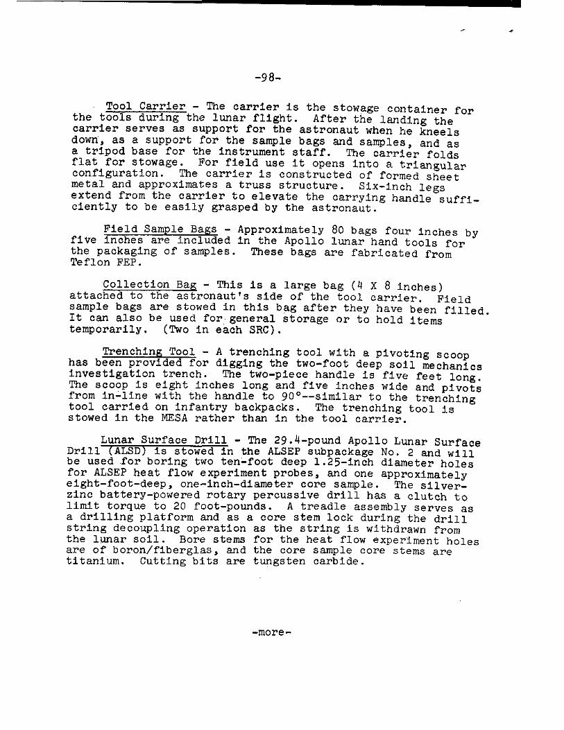
-98-
Tool Carrier - The carrier is the stowage container for the tools during the lunar flight. After the landing the carrier serves as support for the astronaut when he kneels down, as a support for the sample bags and samples, and as a tripod base for the instrument staff. The carrier folds flat for stowage. For field use it opens into a triangular configuration. The carrier is constructed of formed sheet metal and approximates a truss structure. Six-inch legs extend from the carrier to elevate the carrying handle suffi-ciently to be easily grasped by the astronaut.
Field Sample Bags - Approximately 80 bags four inches by titre inches are included in the Apollo lunar hand tools for the packaging of samples. These bags are fabricated from Teflon FEP.
Collection Bag - This is a large bag (4 X 8 inches) attached to the astronaut's side of the tool carrier. Field sample bags are stowed in this bag after they have been filled. It can also be used for general storage or to hold items temporarily. (Two in each SRC).
Trenching Tool - A trenching tool with a pivoting scoop has been provided for digging the two-foot deep soil mechanics investigation trench. The two-piece handle is five feet long. The scoop is eight inches long and five inches wide and pivots from inline with the handle to 90 °--similar to the trenching tool carried on infantry backpacks. The trenching tool is stowed in the MESA rather than in the tool carrier.
Lunar Surface Drill - The 29.4-pound Apollo Lunar Surface Drill (ALSD) is stowed in the ALSEP subpackage No. 2 and will be used for boring two ten-foot deep 1.25-inch diameter holes for ALSEP heat flow experiment probes, and one approximately eight-foot-deep, one-inch-diameter core sample. The silver-zinc battery-powered rotary percussive drill has a clutch to limit torque to 20 foot-pounds. A treadle assembly serves as a drilling platform and as a core stem lock during the drill string decoupling operation as the string is withdrawn from the lunar soil. Bore stems for the heat flow experiment holes are of boron/fiberglas, and the core sample core stems are titanium. Cutting bits are tungsten carbide.
-more-
-99-
Apollo 13 Grew Menu
More than 70 items comprise the food selection list of freeze-dried rehydratable, wet-pack and spoon-bowl foods. Balanced meals for five days have been packed in man/day overwraps. Items similar to those in the daily menus have been packed in a snack pantry. The snack pantry permits the crew to locate easily a food item in a smorgasbord mode with-out having to "rob" a regular meal somewhere down deep in a storage box.
Water for drinking and rehydrating food is obtained from two sources in the command module--a dispenser for drinking water and a water spigot at the food preparation station sup-plying water at about 155 or 55° F. The potable water dis-penser squirts water continuously as long as the trigger is held down, and the food preparation spigot dispenses water in one-ounce increments.
A continuous-feed hand water dispenser similar to the one in the command module is used aboard the lunar module for cold-water rehydration of food packets stowed aboard the LM.
After water has been injected into a food bag, it is kneaded for about three minutes. The bag neck is then cut off and the food squeezed into the crewman's mouth. After a meal, germicide pills attached to the outside of the food bags are placed in the bags to prevent fermentation and gas formation. The bags are then rolled and stowed in waste disposal compartments.
The day-by-day, meal-by-meal Apollo 13 Menu for Com-mander Lovell is on the following page as a typical five-day menu for each crewman.
-more-
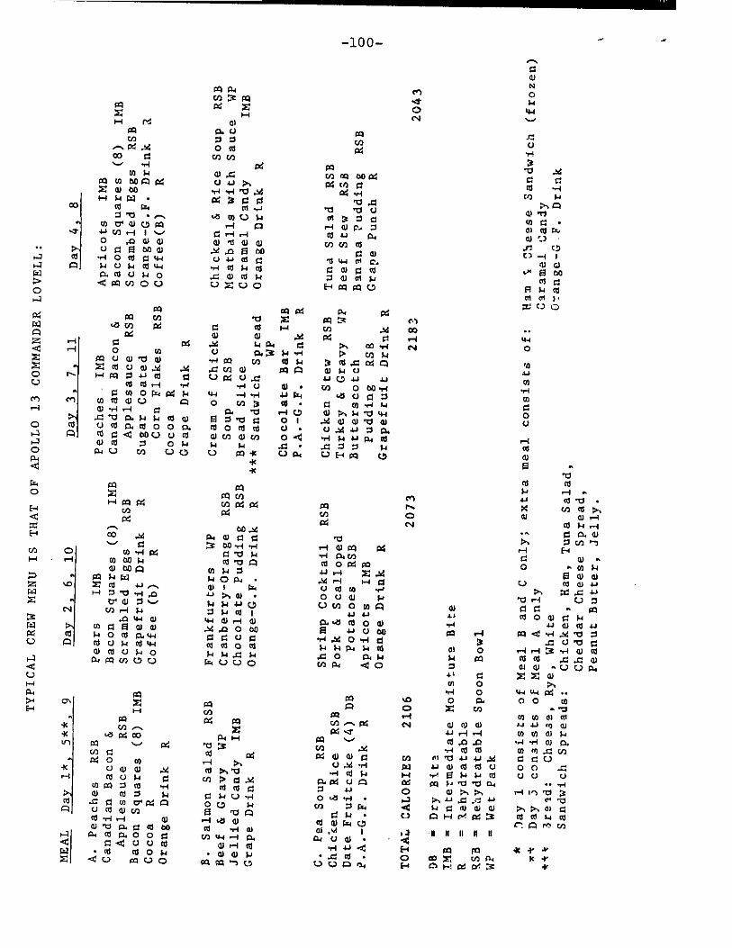
-100-
PG1 Z o-i H Pa
cel Pr En PQ Pd >1
(11
Ir
N re) 0 ...I )4 0 44 c%4 ......•
Pa 0. c) P1 -C. u) 0 0 u) c.)
.-. d..SC co 0
0 0 CO C/5
g 1-1
...., 4-1 g pa -0 ...td 0 H al 4 cn lag 00 g 0 0
pc1 Cf) b0 05 c4 c.) 4.) ON r4 cn o al •.-i Z a) 00 •.4 -.I 1:, ..s4 1:4 ..-1 cn )4 1-4 H g • g 3 0 0 10 4 >, A
0 fr. al .4,-4 "0 "0 u a) -0
0 -0 • .--, to 0' W 0 fal
4-F ra r-I 1 ..-, 0 .0 C1) cl)
.as to 0 H 1-1 (0
0 1--1 I-.1 0 ol 0 a)
tn 3 0 0 H a) p.. 0
CO 1-1 br u) to ca
0 0 • a) 0 ET, 0) ''..) •
,J-: C. •• u 0 S oo al -se ..0 El 00 0 a) c) -I 1 .4 ctl -,-1 o 0 0 F44 (../ il 0 0 0 ir-i vl O. f'D a) ..-.1 A 14 c.) Fr 0 44 -4.4C41 0 ca 0 CO 1," Ei PO cx1 0. 0 c) )4 o 4 0 0 )4 0 al at p ca 0 > Q. Pa cn 0 0 r...) Z 0 0 E 1 PI al 0 F1 14 ctS 0 ai at p
41 El it "0
cd al )4 .--I 4.
ce) 4.4 o "a • 00 N.• X cn ca p... Cl) 0 0.1 CU 1-1
g C■1 ca )4 .4 . - Cl 0. 0
'Cl >-. 0 vl 1-") 1-1 a) rrl ig 1-♦ El •••1 CI. ff) d 0 O o g pa 0 .. 14 $.4
...s4 9-1 ...1 0 [..) 03 01 .1-1
O C.) 0.1 I. V 1-1 C..) 0
0 cn 0 m P a) 0 0 . 00
4.) 1-1 44 0 0 ► 0 1•4 0, 0 cd 0 0 -4-4 4) W a .1-J C.) 40 p2 ••-• pl •ce •-1 ,S4 '10 0
•t-1 ..,W 0 4-1 CI 3 -0 c.1 '0 0 $.4 3-1 Pr $.4 ad 01 0 0-1 r-1 3 .1-1 a) 0i
4 0 0. ).4 1-4 14 CO CC .4 .0 (1.) En a, .4 0 0 CU (1) a• C..) C.) Or
41 Cl Z Z ci) m o
•H 40 4-4 4-4 g ••
MI ...o 0 sa, o 0 co
A 0 X En - ^O
00 r-I 03 01 41 at
col .-.. g tN a) 41 a) J-.1 r.) ra pj
g ....7 1-1 r-I --I co co al )4 00 ,....... 0 .1a Xt ....I ri o) 0, tr) .4 .,..4 CZ 0 CR to .0 cf) 1:4 a) a) 0 cf) ni •0 41 4.J ,.W 0 0 0
U .SG vi J +-I ci) 10 13 U 0 0 .0
.-4 0 )4 1-4 •,-* El Fr 3.1 0 ci (..) U P• g 0 A g clq P 'Cl "CI 0-1 •• "-I O 4.+ 0 0) ›., P, r-1 in •c, O t4!) •,-4 • 1.-1 ›, .1-, .0 -0. 4-5 ri •-0
co 0 Fx. It $.4 0 al cli W ON P-, C4 4 O 14 • C1 03 H C.! g M 0) 01 LI 0
0:1 0) Fir C, C": al r'' cn os ...4 I 1 ? N II II II II cw c.) a) • -4
.1-1 +-I -4 E-4 as FO * .1' •4* • .0 0 • 0 ea z c.,3 P., x •1'
LI VAS E-1 en ' red3 4t
Pa ra
X21 V) t
P4 •z4 0 Co
Pq 1.1 cl) -0 a)
O (71 U a)
N. F-r pl 0 4-1 st r.J cd Cd 1-1 •■-1
1/1 0 1.F.4 re )4 Cel
▪
Co 0 W 0 A W rl •--1
›, .0 'CI 1:1. $-1 $.4 ca O ezi 0 0 sa. 0 0 0 a.
cd G ".4 PO U c.) a)sd a I-4
0 R.0 En U0
•t
as g 04 Pd 01 X PP .='" of
• 0 H Cl) ad 00 •.
W a) ,M PG Cl 1--I t44 .W 14 0-4 0 P.• 00 1-1 v./ 0 U 0. M P vg CO k
4-1 01 vl RI 1-4 g ai .0 1:4 q '1) .0 C/1 W SP A W 14 0 .3.4 U g c.) 4 4.1. cz 4.1 44 co
cn 0 PO 4-1 4-4
44 ) c . ) si 0 CO Cl co •••I LI 0
W >, )4 'V LH o
.:r, co 0 -0 al 0 u ... 4.4 0 G. •r1 f.i .I..) p.i a, 1-t ,.= 0 14 03 OE-c00 U a)
•,-1 0 a) • 4-1 --1 •1-1 4.) riq o cn 3
0. -01 I-4 0 la 0 "0 0 0 1 0 o 0 0 U • 0 cn a) co 0 41 14 P .4 •
r...) PI 41 004
FT.4 p:1 pci 0 X PP CO
H PI PG cn g g E-4 Cl) r4 -‹ 04
E-1 IX .4 R4 W 0 0 ..-• 0 nO -,-4 4-1
u) 0 co -T4 CG 0 'V $.1
H - .--1 CO b0 Fr 0 -0 A
a) 1)0 A 0 Fr 0
.. PC1 Fr 4.1 F4 0 Ati • Z ..0 Z 0:1 44 .--... .344 4 r7-1 47 F-I 0 -0 -r1 -0 .0 P, a) • X ., Cr al 0 •-• 1.4 i-i .1-1 C,D
Cs] C15 I-A Sr 0 S-1 011 I
.0 4-1 0) 4-1 0) r-I 1:1) 41 >, co 0 la co a) -M .0 0 CO PG 0 H 0 ca 0. tH 0 0 c-) 0 C.) A 0 c.) Fr a) Li-t aa 0 0 0
W ca 0 $4 0 H F4 -0 H 1--1 R4 PP rn 0 r...) FT-1 L.) r-.) 0
Pr pa >4 0N Z pia El 1-1 V)
... PI g PI
4c Cl).-. •
4c 14 pG CO Pr .4
u) 0 0 PG - pG 0 ill H p,
4c U a, a) .ha 0 P., -01
r-i cd c) 14 0 u) > 0 .V cn go 0 al -1.4 cd ca 0
7, a) rd 0 Fr 0 )4 V •-1
ca .0 0 co 0, r4 A 0 0 )4
A U ca al u) H ID A cd "-I I-I Iv ,-•1 to al 0 -0 a. 0 ct 450 m -r-o 0.)
I-1 0-1 cri CL. 0 0 0 Crl 44 -I C.
.4 0 -.4 o 0 0 a) r-I al
14 •cti c001.4 • a) a) FA
X -4U pp U0 szi cri '-) 0

-101-
Personal Hygiene
Crew personal hygiene equipment aboard Apollo 13 includes body cleanliness items, the waste management system and one medical kit.
Packaged with the food are a toothbrush and a two-ounce tube of toothpaste for each crewman. Each man-meal package contains a 3.5-by-4-inch wet-wipe cleansing towel. Addition-ally, three packages of 12-by-12-inch dry towels are stowed beneath the command module pilot's couch. Each package con-tains seven towels. Also stowed under the command module pilot's couch are seven tissue dispensers containing 53 three-ply tissues each.
Solid body wastes are collected in plastic defecation bags which contain a germicide to prevent bacteria and gas formation. The bags are sealed after use and stowed in empty food containers for post-flight analysis.
Urine collection devices are provided for use while wearing either the pressure suit or the inflight coveralls. The urine is dumped overboard through the spacecraft urine dump valve in the CM and stored in the LM.
Medical Kit
The 5X5X8-inch medical accessory kit is stowed in a com-partment on the spacecraft right side wall beside the lunar module pilot couch. The medical kit contains three motion sickness injectors, three pain suppression injectors, one two-ounce bottle first aid ointment, two one-ounce bottles eye drops, three nasal sprays, two compress bandages, 12 adhesive bandages, one oral thermometer, and four spare crew biomedical harnesses. Pills in the medical kit are 60 antibiotic, 12 nausea, 12 stimulant, 18 pain killer, 60 decongestant, 24 diarrhea, 72 aspirin and 21 sleeping. Additionally, a small medical kit containing four stimulant, eight diarrhea, two sleeping and four pain killer pills, 12 aspirin, one bottle eye drops, two compress bandages, 8 decongestant pills, one pain injector, one bottle nasal spray is stowed in the lunar module flight data file compartment.
-more-
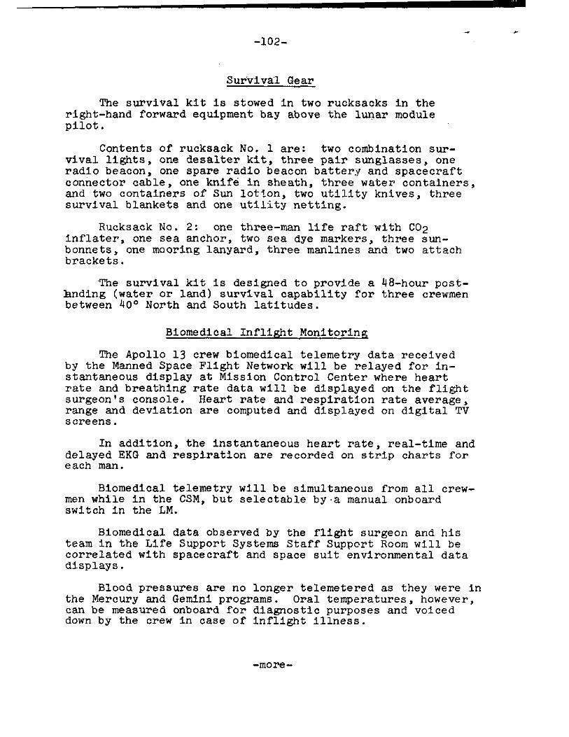
-102-
Survival Gear
The survival kit is stowed in two rucksacks in the right-hand forward equipment bay above the lunar module pilot.
Contents of rucksack No. I are: two combination sur-vival lights, one desalter kit, three pair sunglasses, one radio beacon, one spare radio beacon battery and spacecraft connector cable, one knife in sheath, three water containers, and two containers of Sun lotion, two utility knives, three survival blankets and one utility netting.
Rucksack No. 2: one three-man life raft with CO2 inflater, one sea anchor, two sea dye markers, three sun-bonnets, one mooring lanyard, three manlines and two attach brackets.
The survival kit is designed to provide a 48-hour post-hnding (water or land) survival capability for three crewmen between 40 ° North and South latitudes.
Biomedical Inflight Monitoring
The Apollo 13 crew biomedical telemetry data received by the Manned Space Flight Network will be relayed for in-stantaneous display at Mission Control Center where heart rate and breathing rate data will be displayed on the flight surgeon's console. Heart rate and respiration rate average, range and deviation are computed and displayed on digital TV screens.
In addition, the instantaneous heart rate, real-time and delayed EKG and respiration are recorded on strip charts for each man.
Biomedical telemetry will be simultaneous from all crew-men while in the CSM, but selectable by•a manual onboard switch in the LM.
Biomedical data observed by the flight surgeon and his team in the Life Support Systems Staff Support Room will be correlated with spacecraft and space suit environmental data displays.
Blood pressures are no longer telemetered as they were in the Mercury and Gemini programs. Oral temperatures, however, can be measured onboard for diagnostic purposes and voiced down by the crew in case of inflight illness.
-more-

-103-
Energy expended by the crewmen during EVA will be determined indirectly using a metabolic computation pro-gram based on three separate measurements:
1) Heart rate portion -- Heart rate will be determined from telemetered EKG and converted to oxygen con-sumption (litre/min) and heat production (BTU/hour) based on pre-flight calibration curves. These curves are determined from exercise response tests utilizing a bicycle ergometer.
2) Oxygen usage portion -- Oxygen usage will be determined from the telemetered measurement of PLSS oxygen supply pressure. Suit leak determined pre-flight is taken into account. Heat production will be calculated from oxygen usage.
3) Liquid cooled garment temperature portion -- The amount of heat taken up by the liquid cooled garment will be determined from telemetered measurements of the LCG water temperature inlet and change in/out. This measurement (the amount of heat taken up by the water) plus an allowance made for sensible and latent heat loss, radiant heat load, and possible heat storage will provide an indication of heat production by the crewman.

-104 -
Training
The crewmen of Apollo 13 have spent more than five hours of formal crew training for each hour of the lunar-launching mission's ten-day duration. More than 1,000 hours of training were in Apollo 13 crew training syllabus over and above the normal preparations for the mission--technical briefings and reviews, pilot meetings and study.
The Apollo 13 crewmen also took part in prelaunch testing at Kennedy Space Center, such as altitude chamber tests and the countdown demonstration tests (CDDT) which provided the crew with thorough operational knowledge of the complex vehicle.
Highlights of specialized Apollo 13 crew training topics are:
* Detailed series of briefings on spacecraft systems, operation and modifications.
* Saturn launch vehicle briefings on countdown, range safety, flight dynamics, failure modes and abort conditions. The launch vehicle briefings were updated periodically.
* Apollo Guidance and Navigation system briefings at the Massachusetts Institute of Technology Instrumentation Laboratory.
* Briefings and continuous training on mission photo-graphic objectives and use of camera equipment.
* Extensive pilot participation in reviews of all flight procedures for normal as well as emergency situations.
* Stowage reviews and practice in training sessions in the spacecraft, mockups and command module simulators allowed the crewmen to evaluate spacecraft stowage of crew-associated equipment.
* More than 400 hours of training per man in command module and lunar module simulators at MSC and KSC, including closed-loop simulations with flight controllers in the Mission Control Center. Other Apollo simulators at various locations were used extensively for specialized crew training.
-105-
* Lunar surface briefings and some 20 suited 1-g walk-throughs of lunar surface EVA operations covering lunar geology and microbiology and deployment of experiments in the Apollo Lunar Surface Experiment Package (ALSEP). Train- ing in lunar surface EVA included practice sessions with lunar surface sample gathering tools and return containers, cameras, the erectable S-band antenna and the modular equipment stowage assembly (MESA) housed in the LM descent stage.
* Proficiency flights in the lunar landing training vehicle (LLTV) for the commander.
* Zero--g and one-sixth g aircraft flights using command module and lunar module mockups for EVA and pressure suit doffing/donning practice and training.
* Underwater zero-g training in the MSC Water Immersion Facility using spacecraft mockups to further familiarize crew with all aspects of CSM-LM docking tunnel intravehicular transfer and EVA in pressurized suits.
* Water egress training conducted in indoor tanks as well as in the Gulf of Mexico, included uprighting from the Stable II position (apex down) to the Stable I position (apex up), egress onto rafts donning Biological Isolation Garments (BIGs), decontamination procedures and helicopter pickup.
* Launch pad egress training from mockups and from the actual spacecraft on the launch pad for possible emergencies such as fire, contaminants and power failures.
* The training covered use of Apollo spacecraft fire suppression equipment in the cockpit.
* Planetarium reviews at Morehead Planetarium, Chapel Hill, N.C., and at Griffith Planetarium, Los Angeles, Calif., of the celestial sphere with special emphasis on the 37 navigational stars used by the Apollo guidance computer.
-more-
-106-
NATIONAL AERONAUTICS AND SPACE ADMINISTRATION
wASHINGTM4, D. C. 20546
BIOGRAPHICAL DATA
NAME: James Arthur Lovell, Jr. (Captain. USN) NASA Astronaut
BIRTHPLACE AND DATE: Born March 25, 1928, in Clevelpnd, Ohio. His mother, Mrs. Blanche Lovell, resideo !4t T.:dgewater Beach, Florida.
PHYSICAL DESCRIPTION: Blond hair; blue eyes; height: 5 feet 11 inches; weight: 170 pounds.
EDUCATION: Graduated from Juneau High School, Milwaukee, Wisconsin; attended the University of Wisconsin for 2 years, then received a Bachelor of Science degree from the United States Naval Academy in 1952; presented an Honorary Doctorate from Illinois WesleyAn University in 1969.
MARITAL STATUS: Married to the former Marilyn Ge'1ach of Milwaukee, Wisconsin. Her parents, Mr. and Mrs. Carl Gerlach, are residents of Milwaukee.
CHILDREN: Barbara L., October 13, 1953; James A., February 15, 1955; Susan K., July 14, 1958; Jeffrey C., January 14, 1966.
RECREATIONAL INTERESTS: His hobbies are golf, swimming, handball, and tennis.
ORGANIZATIONS: Member of the Society of Experimental Test Pilots and the Explorers Club.
SPECIAL HONORS: Awarded the NASA Distinguished Service Medal, two NASA Exceptional Service Medals, the Navy Astronaut Wings, the Navy Distinguished Service Medal, and two Navy Distinguished Flying Crosses; recipient of the 1967 FAI De Laval and Gold Space Medals (Athens, Greece), the American Academy of Achievement Golden Plate Award, the City of New York Gold Medal in 1969, the City of Houston Medal'for Valor in 1969, the National Geographic Society's Hubbard Medal in 1969, the National Academy of Television Arts and Sciences Special Trustees Award in 1969, and the Institute of Navigation Award in 1969.
-more-
-107-
Co-recipient of the American Astronautical Society Flight Achievement Awards in 1966 and 1968, the Harmon Inter-national Trophy in 1966 and 1967, the Robert H. Goddard Memorial Trophy in 1969, the H. H. Arnold Trophy for 1969, the General Thomas D. White USAF Space Trophy for 1968, the Robert J. Collier Trophy for 1968, and the 1969 Henry G. Bennett Distinguished Service Award.
EXPERIENCE: Lovell, a Navy Captain, received flight training following graduation from Annapolis in 1952.
He has had numerous naval aviator assignments including a 4-year tour as a test pilot at the Naval Air Test Center, Patuxent River, Maryland. While there he served as program manager for the F4H weapon system evaluation. A graduate of the Aviation Safety School of the Univer-sity of Southern California, he also served as a flight instructor and safety engineer with Fighter Squadron 101 at the Naval Air Station, Oceana, Virginia.
He has logged more than 4,407 hours flying time--more than 3,000 hours in :,et aircraft.
CURRENT ASSIGNMENT: Captain Lovell was selected as an astronaut by NASA in September 1962. He has since served as back-up pilot for the Gemini 4 flight and backup command pilot for the Gemini 9 flight.
On December 4, 1965, he and Command pilot Frank Borman were launched into space on the history-making Gemini 7 mission. The flight lasted 330 hours and 35 minutes, during which the following space firsts were accomplished: longest manned space flight; first rendezvous of two manned maneuverable spacecraft, as Gemini 7 was joined in orbit by Gemini 6; and longest .multi-manned space flight. It was also on this flight that numerous technical and medical experiments were completed successfully.
The Gemini 12 mission, with Lovell and pilot Edwin Aldrin, began on November 11, 1966. This 4-day, 59-revolution flight brought the Gemini Program to a successful close. Major accomplishements of the 94-hour 35-minute flight included a third-revolution rendezvous with the previously launched Agena (using for the first time backup onboard computations due to radar failure); a tethered station-keeping exercise,; retrieval of a micrometeorite experi-, ment package from the spacecraft exterior; an evaluation of the use of body restraints specially designed for completing work tasks outside of the spacecraft; and completion of numerous photographic experiments, high-lights of which are the first pictures taken from space of an eclipse of the sun.
-more-
-108-
Gemini 12 ended with retrofire at the beginning of the 60th revolution, followed by the second consecutive fully automatic controlled reentry of a spacecraft, and a landing in the Atlantic within 2 1/2 miles of the USS WASP.
As a result of his participation in the Gemini 7 and 12 flights, Lovell logged 425 hours and 10 minutes in space. Aldrin established a new EVA record by completing 5 1/2 hours outside the spacecraft during two standup EVAs and one umbilical EVA.
Lovell served as command module pilot for the epic six-day journey of Apollo 8--man's maiden voyage to the moon --December 21-27, 1968. Apollo 8 was the first manned spacecraft to be lifted into near-earth orbit by a 7 1/2-million pound thrust Saturn V launch vehicle, and all events in the flight plan occurred as scheduled with unbelievable accuracy.
A "go" for the translunar injection burn was given midway through the second near-earth orbit, and the restart of the S-IVB third stage to effect this maneuver increased the spacecraft's velocity to place it on an intercept course with the moon. Lovell and fellow crew members, Frank Borman (spacecraft commander) and William A. Anders (lunar module pilot), piloted their spacecraft some 223,000 miles to become the first humans to leave the earth's influence; and upon reaching the moon on December-24, they performed the first critical maneuver to place Apollo 8 into a 60 by 168 nautical miles lunar orbit.
Two revolutions later, the crew executed a second maneuver using the spacecraft's 20,500-pound thrust service module propulsion system to achieve a circular lunar orbit of 60 nautical miles. During their ten revolutions of the moon, the crew conducted live television transmissions of the lunar surface and performed such tasks as landmark and Apollo landing site tracking, vertical stereo photo-graphy and stereo navigation photography, and sextant navigation using lunar landmarks and stars. At the end of the tenth lunar orbit, they executed a transearth injection burn which placed Apollo 8 on a proper trajectory for the return to earth.
-more-
-109-
The final leg of the trip required only 58 hours, as compared to the 69 hours used to travel to the moon, and Apollo 8 came to a successful conclusion on Dec-ember 27, 1968. Splashdown occurred at an estimated 5,000 yeards from the USS YORKTOWN, following the successful negotiation of a critical 28-mile high reentry corridor at speeds close to 25,000 miles per hour.
Captain Lovell has since served as the backup spacecraft commander for the Apollo 11 lunar landing mission. He has completed three space flights and holds the U.S. Astronaut record for time in space with a total of 572 hours and 10 minutes.
SPECIAL ASSIGNMENT: In addition to his regular duties as an astronaut, Captain Lovell continues to serve as Special Consultant to the President's Council on Physical Fitness and Sports--an assignment he has held since June 1967.
CURRENT SALARY: $1,717.28 per month.
-more-
-110-
NATIONAL AERONAUTICS AND SPACE ADMINISTRATION
WASHINGTON. D. C. 20546
BIOGRAPHICAL DATA
NAME: Thomas Kenneth Mattingly II (Lieutenant Commander, USN) NASA Astronaut
BIRTHPLACE AND DATE: Born in Chicago, Ill., March 17, 1936. His parents, Mr. and Mrs. Thomas K. Mattingly, now reside in Hialeah, Fla.
PHYSICAL DESCRIPTION: Brown hair; blue eyes; height: 5 feet 10 inches; weight: 140 pounds.
EDUCATION: Attended Florida elementary and secondary schools and is a graduate of Miami Edison High School, Miami, Fla.; received a Bachelor of Science degree in Aeronautical Engineering from Auburn University in 1958.
MARITAL STATUS: Single
RECREATIONAL INTERESTS: Enjoys water skiing and playing handball and tennis.
ORGANIZATIONS: Member of the American Institute of Aero-nautics and Astronautics and the U.S. Naval Institute.
EXPERIENCE: Prior to reporting for duty at the Manned Spacecraft Center, he was a student at the Air Force Aerospace Research Pilot School.
He began his Naval career as an Ensign in 1958 and received his wings in 1960. He was then assigned to VA-35 and flew A1H aircraft aboard the USS SARATOGA from 1960 to 1963. In July 1963, he served in VAH-11 deployed aboard the USS FRANKLIN D. ROOSEVELT where he flew the A3B aircraft for two years.
He has logged 3,700 hours of flight time--1,946 hours in jet aircraft.
CURRENT ASSIGNMENT: Lt Commander Mattingly is one of the 19 astronauts selected by NASA in April 1966. He served as a member of the astronaut support crews for the Apollo 8 and 11 missions.
CURRENT SALARY: $1,293.33 per month.
NATIONAL AERONAUTICS AND SPACE ADMINISTRATION
WASHINGTON. D. C. 20546
BIOGRAPHICAL DATA
NAME: Fred Wallace Haise, Jr. (Mr.) NASA Astronaut
BIRTHPLACE AND DATE: Born in Biloxi, Miss., on Nov. 14, 1933; his mother, Mrs. Fred W. Raise, Sr., resides in Biloxi.
PHYSICAL DESCRIPTION: Brown hair; brown eyes; height: 5 feet 9 1/2 inches; weight: 150 pounds.
EDUCATION: Graduated from Biloxi High School, Biloxi, Miss.; attended Perkinston Junior College (Association of Arts); received a Bachelor of Science degree with honors in Aeronautical Engineering from the University of Oklahoma in 1959.
MARITAL STATUS: Married to the former Mary Griffin Grant of Biloxi, Miss. Her parents, Mr. and Mrs. William J. Grant, Jr., reside in Biloxi.
CHILDREN: Mary M., January 25, 1956; Frederick T., May 13, 1958; Stephen W., June 30, 1961.
ORGANIZATIONS: Member of the Society of Experimental Test Pilots, Tau Beta Pi, Sigma Gamma Tau, and Phi Theta Kappa.
SPECIAL HONORS: Recipient of the A. B. Honts Trophy as the outstanding graduate of class 64A from the Aerospace Research Pilot School in 1964; awarded the American Defense Ribbon and the Society of Experimental Test Pilots Ray E. Tenhoff Award for 1966.
EXPERIENCE: Haise was a research pilot at the NASA Flight Research Center at Edwards, Calif., before coming to Houston and the Manned Spacecraft Center; and from September 1959 to March 1963, he was a research pilot at the NASA Lewis Research Center in Cleveland, Ohio. During this time, he authored the following papers which have been published: a NASA TND, entitled "An Evaluation of the Flying Qualities of Seven General-Aviation Air-craft;" NASA TND 3380, "Use of Aircraft for Zero Gravity Environment, May 1966;" SAE Business Aircraft Conference Paper, entitled "An Evaluation of General-Aviation Air-craft Flying Qualities," March 30-April 1, 1966; and a paper delivered at the tenth symposium of the Society of
-more-
-112-
Experimental Test Pilots, entitled "A Quantitative/ Qualitative Handling Qualities Evaluation of Seven General-Aviation Aircraft," 1966.
He was the Aerospace Research Pilots School's out-standing graduate of Class 64A and served with the U.S. Air Force from October 1961 to August 1962 as a tactical fighter pilot and as Chief of the 164th Standardization-Evaluation Flight of the 164th Tactical Fighter Squadron at Mansfield, Ohio. From March 1957 to September 1959, he was a fighter-interceptor pilot with the 185th Fighter Interceptor Squadron in the Okla-homa Air National Guard.
He also served as a tactics and all weather flight instructor in the U.S. Navy Advanced Training Command at NAAS Kingsville, Texas, and was assigned as a U.S. Marine Corps fighter pilot to VMF-533 and 114 at MCAS Cherry Point, N.C., from March 1954 to September 1956.
His military career began in October 1952 as a Naval Aviation Cadet at the Naval Air Station in Pensacola, Fla.
He has accumulated 5,800 hours flying time, including 3,000 hours in jets.
CURRENT ASSIGNMENT: Mr. Haise is one of the 19 astronauts selected by NASA in April 1966. He served as backup lunar module pilot for the Apollo 8 and 11 missions.
CURRENT SALARY: $1,698.00 per month.
-more-
-113-
LAUNCH COMPLEX 39
Launch Complex 39 facilities at the Kennedy Space Center were planned and built specifically for the Apollo Saturn V, the space vehicle being used in the United States manned lunar exploration program.
Complex 39 introduced the mobile concept of launch operations in which the space vehicle is thoroughly checked out in an enclosed building before it is moved to the launch pad for final preparations. This affords greater protection from the elements and permits a high launch rate since pad time is minimal.
Saturn V stages are shipped to the Kennedy Space Center by ocean-going vessels and specially designed air-craft. Apollo spacecraft modules are transported by air and first taken to the Manned Spacecraft Operations Building in the Industrial Area south of Complex 39 for preliminary checkout, altitude chamber testing, and assembly.
Apollo 12 is the sixth Saturn V/Apollo space vehicle to be launched from Complex 39's Pad A, one of two octagonal launch pads which are 3,000 feet across. The major components of Complex 39include:
1. The Vehicle Assembly Building, heart of the complex, is where the 363-foot-tall space vehicle is assembled and tested. It contains 129.5 million cubic feet of space, covers eight acres, is 716 feet long and 518 feet wide. Its high bay area, 525 feet high, contains four assembly and checkout bays and its low bay area - 210 feet high,442 feet wide and 274 feet long - contains eight stage-preparation and check-out cells. There are 141 lifting devices in the building, ranging from one-ton hoists to two 250-ton high lift bridge cranes.
2. The Launch Control Center, a four-story structure adjacent and to the south of the Vehicle Assembly Building is a radical departure from the dome-shaped, "hardened" blockhouse at older launch sites. The Launch Control Center is the electronic "brain" of Complex 39 and was used for checkout and test operations while Apollo 12 was being as-sembled inside the Vehicle Assembly Building high bay. Three of the four firing rooms contain identical sets of control and monitoring equipment so that launch of one vehicle and checkout of others may continue simultaneously. Each firing room is associated with a ground computer facility to provide data links with the launch vehicle on its mobile launcher at the pad or inside the Vehicle Assembly Building.
-more-
-114-
3. The Mobile Launcher, 445 feet tall and weighing 12 million pounds, is a transportable launch base and um-bilical tower for the space vehicle.
4. 112212n!E=IILLL used to move mobile launchers into the Vehicle Assembly Building and then - with their space vehicles - to the launch pad, weigh six million pounds and are among the largest tracked vehicles known. The Trans-porters - there are two - are 131 feet long and 114 feet wide. Powered by electric motors driven by two 2,750-horsepower diesel engines, the vehicles move on four double-tracked crawlers, each 10 feet high and 40 feet long. Maximum speed is about one-mile-per-hour loaded and two miles-per-hour unloaded. The three and one-half mile trip to Pad A with a mobile launcher and space vehicle takes approximately seven hours. Apollo 12 rollout to the pad occurred on December 15, 1969.
5. The Crawlerway is the roadway for the transporter and is 131 feet wide divided by a median strip. This is the approximate width of an eight-lane turnpike and the roadbed is designed to accommodate a combined weight of more than 18 million pounds.
6. The Mobile Service Structure is a 402-foot-tall, 9.8 million pound tower used to service the Apollo space vehicle at the pad. Moved into place about the Saturn V/Apollo space vehicle and its mobile launcher by a transporter, it contains five work platforms and provides 360-degree platform access to the vehicle being prepared for launch. It is removed to a parking area about 11 hours before launch.
7. A Water Deluge System will provide about a million gallons of industrial water for cooling and fire prevention during the launch of Apollo 13. The water is used to cool the mobile launcher, the flame trench and the flame deflector above which the mobile launcher is positioned.
8. The Flame Deflector is an "A"-shaped, 1.3 million pound structure moved into the flame trench beneath the launcher prior to launch. It is covered with a refractory material designed to withstand the launch environment, The flame trench itself is 58 feet wide and approximately six feet above mean sea level at the base.
-more-

-115-
9. The Pad Areas - A and B - are octagonal in shape and have center hardstands constructed of heavily reinforced concrete. The top of Pad A stands about 48 feet above sea level. Saturn V propellants - liquid oxygen, liquid hydrogen and RP-1, the latter a high grade kerosene - are stored in large tanks spaced near the pad perimeter and carried by pipe- lines from the tanks to the nad, up the mobile launcher and into the launch vehicle propellant tanks. Also located in the pad area are pneumatic, high pressure gas, electrical, and industrial water support facilities. Pad B, used for the launch of Apollo 10, is located 8,700 feet north of Pad A.
-more-

-116-
MISSION CONTROL CENTER
The Mission Control Center at the Manned Spacecraft Center, Houston, is the focal point for Apollo flight control activities. The center receives tracking and telemetry data from the Manned Space Flight Network which in turn is pro-cessed by the MCC Real-Time Computer Complex for display to flight controllers in the Mission Operations Control Room (MOCK) and adjacent staff support rooms.
Console positions in the two identical MOCRs in Mission Control Center fall into three basic operations groups: mission command and control, systems operations, and flight dynamics.
Positions in the command and control group are:
* Mission Director -- responsible for overall mission conduct.
* Flight Operations Director -- represents MSC management.
* Flight Director -- responsible for operational decisions and actions in the MOCK.
* Assistant Flight Director -- assists flight director and acts in his absence.
* Flight Activities Officer -- develops and coordinates flight plan.
* Department of Defense Representative -- coordinates and directs DOD mission support.
-117-
* Network Controller -- responsible to FD for Manned Space Flight Network status and troubleshooting; MCC equip-ment operation.
* Surgeon -- monitors crew medical condition and informs FD of any medical situation affecting mission.
* Spacecraft Communicator (Capcom) -- serves as voice contact with flight: crew.
* Experiments Officer -- coordinates operation and control of onboard flight experiments.
* Public Affairs Officer -- reports mission progress to public through commentary and relay of live air-to-ground transmissions.
Systems Operations Group:
* Environmental, Electrical and Instrumentation Engineer (EECOM) -- monitors and troubleshoots command/service module environmental, electrical, and sequential systems.
* Guidance, Navigation and Control Engineer (GNC) --monitors and troubleshoots CSM guidance, navigation, control, and propulsion systems.
* LM Environmental and Electrical Engineer (TELCOM) --LM counterpart to EECOM.
* LM Guidance, Navigation and Control Engineer (Control)--LM counterpart to GNC.
* Booster Systems Engineer (ESE) (three positions) --responsible for monitoring launch vehicle performance and for sending function commands.
* Communications Systems Engineer (CSE) (call sign INCO) and Operations and Procedures Officer (O&P) -- share respon-sibility for monitoring and troubleshooting spacecraft and lunar surface communication systems and for coordinating MCC procedures with other NASA centers and the network.
Flight Dynamics Group:
* Flight Dynamics Officer (FIDO) -- monitors powered flight events and plans spacecraft maneuvers.
* Retrofire Officer (Retro) -- responsible for plannlm deorbit maneuvers in Earth orbit and entry calculation; on lunar return trajectories.
-more-

-118-
* Guidance Officer (Guido) -- responsible for monitoring and updating CSM and LM guidance systems and for monitoring systems performance during powered flight.
Each MOCR operations group has a staff support room on the same floor in which detailed monitoring and analysis is conducted. Other supporting MCC areas include the space-flight Meteorological Room, the Space Environment (radiation) Console, Spacecraft Planning and Analysis (SPAN) Room for detailed spacecraft performance analysis, Recovery Operations Control Room and the Apollo Lunar Surface Experiment Package Support Room.
Located on the first floor of the MCC are the communica-tions, command, and telemetry system (COATS) for processing incoming data from the tracking network, and the real-time computer complex (RTCC) which converts flight data into dis-plays useable to MOOR flight controllers.
-more-
-119-
MANNED SPACE FLIGHT NETWORK
The worldwide Manned Space Flight Network (MSFN) provides reliable, continuous, and instantaneous com-munications with the astronauts, launch vehicle, and spacecraft from liftoff to splashdown. Following the flight, the network will continue in support of the link between Earth and the Apollo experiments left on the lunar surface by the Apollo crew.
The MSFN is maintained and operated by the NASA Goddard Space Flight Center, Greenbelt, Md., under the direction of NASA's Office of Tracking and Data Acquisition. In the MSFN Operations Center (MSFNOC) at Goddard, the Network Director and his team of Operations Managers, with the assistance of a Network Support Team, keep the entire complex tuned for the mission support. Should Houston's mission con-trol center be seriously impaired for an extended time, the Goddard Center becomes an emergency mission control center.
The MSFN employs 12 ground tracking stations equipped with 30- and 85-foot antennas, an instrumented tracking ship, and four instrumented aircraft. For Apollo 13, the network will be augmented by the 210-foot antenna systems at Goldstone, Calif. and at Parkes, Australia, (Australian Commonwealth Scientific and Industrial Research Organization).
NASA Communications Network (NASCOM). The tracking network is linked together by the NASA Communications Network. All information flows to and from MCC Houston and the Apollo spacecraft over this communications system.
The NASCOM consists of almost three million circuit miles of diversely routed communications channels. It uses satellites, submarine cables, land lines, microwave systems, and high frequency radio facilities for access links.
NASCOM control center is located at Goddard. Regional communication switching centers are in London, Madrid, Can-berra, Australia; Honolulu and Guam.
-more-
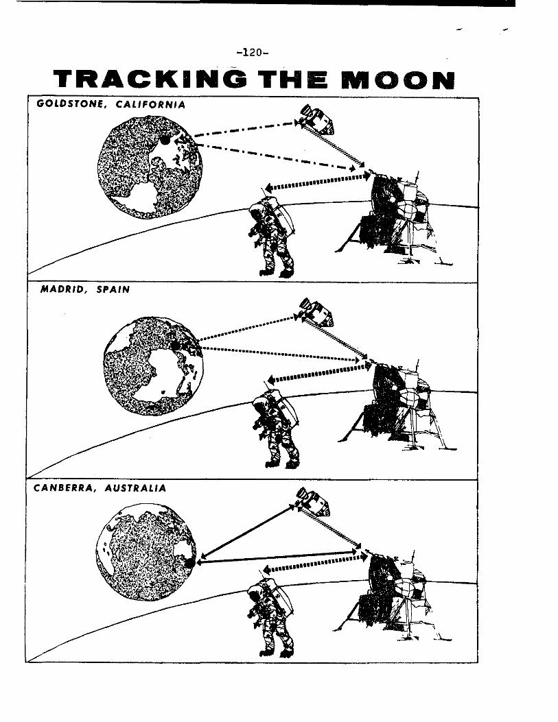
TRACKING THE MOON
-121-
Three Intelsat communications satellites will be used for Apollo 13. One satellite over the Atlantic will link Goddard with stations at Madrid, Canary Islands, Ascension and the Vanguard tracking ship. Another Atlantic satellite will provide a direct link between Madrid and Goddard for TV signals received from the spacecraft. The third satellite over the mid-Pacific will link Carnarvon, Canberra, and Hawaii with Goddard through a ground station at Brewster Flats, Wash.
At G6ddard, NASCOM switching computers simultaneously send the voice signals directly to the Houston flight controllers and the tracking and telemetry data to computer processing complexes at Houston and Goddard. The Goddard Real Time Com-puting Complex verifies performance of the tracking network and uses the collected tracking data to drive displays In the Goddard Operations Control Center.
Establishing the Link -- The Merritt Island tracking station monitors prelaunch test, the terminal countdown, and the first minutes of launch.
An Apollo instrumentation ship (USNS VANGUARD) fills the gaps beyond the range of land tracking stations. For Apollo 13 this ship will be stationed in the Atlantic to cover the insertion into Earth orbit. Apollo instrumented aircraft provide communications support to the land tracking stations during translunar injection and reentry and cover a selected abort area in the event of "no-go" decision after insertion into Earth orbit.
Lunar Bound - Approximately one hour after the space-craft has been injected into its translunar trajectory (some 10,000 miles from the Earth), three prime tracking stations spaced nearly equidistant around the Earth will take over tracking and communicating with Apollo.
Each of the prime stations, located at Goldstone, Madrid and Canberra, has a dual system for use when tracking the command module in lunar orbit and the lunar module in separate flight paths or at rest on the Moon. These stations are equipped with 85-foot antennas.
The Return Trip -- To make an accurate reentry, data from the tracking stations are fed into the MCC computers to develop necessary information for the Apollo 13 crew.
-more-

MA
NN
ED
SPA
CE
FLIG
HT
TRA
CK
ING
NET
WO
RK
-122-
-more-

2 0 V
4
-more-

-12 14-
Appropriate MSFN stations, including the aircraft in the Pacific, provide support during the reentry.
Through the journey to the Moon and return, television will be received from the spacecraft at the three prime stations. In addition, a 210-foot antenna at Goldstone (an antenna of NASA's Deep Space Network) will augment the television coverage while Apollo 13 is near and on the Moon. For black and white TV, scan converters at the stations per-mit immediate transmission of commercial quality TV via NASCOM to Houston, where it will be released to U.S. TV networks.
Black and white TV can be released simultaneously in Europe and the Far East through the MSFN stations in Spain and Australia.
For color TV, the signal will be converted to commercial quality at the MSC Houston. A black and white version of the color signal can be released locally simultaneously through the stations in Spain and Australia.
Network Computers
At fraction-of-a--second intervals, the network's digital data processing systems, with NASA's Manned Spacecraft Center as the focal point, "talk" to each other or to the spacecraft. High-speed computers at the remote sites (tracking ship in-cluded) relay commands or "up-link" data on such matters as control of cabin pressure, orbital guidance commands, or "go-no-go" indications to perform certain functions.
When information originates from Houston, the computers refer to their pre-programmed information for validity before transmitting the required data to the spacecraft.
Such "up-link" information is communicated at a rate of about 1,200 bits-per-second. Communication of spacecraft data between remote ground sites and the Mission Control Center, via high-speed communications links, occurs at twice the rate. Houston reads information from these ground sites at 8,800 bits-per-second.
The computer systems perform many other functions, including:
Assuring the quality of the transmission lines by con-tinually testing data paths.
Verifying accuracy of the messages.
Constantly updating the flight status.
-more-
-1 25-
For "down-link" data, sensors built into the spacecraft continually sample cabin temperature, pressure, and physical information on the astronauts such as heartbeat and respira-tion. These data are transmitted to the ground stations at 51.2 kilobits (12,800 decimal digits) per second.
At MCC the computers:
Detect and select changes or deviations, compare with their stored programs, and indicate the problem areas or pertinent data to the flight controllers;
Provide displays to mission personnel;
Assemble output data in proper formats;
Log data on magnetic tape for the flight controllers.
The Apollo Ship Vanguard
The USNS Vanguard will perform tracking, telemetry, and communication functions for the launch phase and Earth orbit insertion. Vanguard will be stationed about 1,000 miles southeast of Bermuda (28 degrees N., 49 degrees W.).
Apollo Range Instrumentation Aircraft (ARIA)
During the Apollo 13 TLI maneuver, two ARIA will record telemetry data from Apollo and relay voice communication between the astronauts and the Mission Control Center at Houston. The ARIA will be located between Australia and Hawaii.
For reentry, two ARIA will be deployed to the landing area to relay communications between Apollo and Mission Con-trol at Houston and provide position information on the space-craft after the blackout phase of reentry has passed.
The total ARIA fleet for Apollo missions consists of four EC-135A (Boeing 707) jets with 7-foot parabolic antennas installed in the nose section.
-more-
-126-
CONTAMINATION CONTROL PROGRAM
In 1966 an Interagency Committee on Back Contamination (ICBC) was established to assist NASA in developing a pro-gram to prevent contamination of the Earth from lunar mat-erials following manned lunar exploration and to review and approve plans and procedures to prevent back contamination. Committee membership includes representatives from Public Health Service, Department of Agriculture, Department of the Interior, NASA, and the National Academy of Sciences.
The Apollo Back Contamination Program can be divided into three phases. The first phase covers procedures which are followed by the crew while in flight to reduce and, if possible, eliminate the return of lunar surface contaminations in the command module.
The second phase includes recovery, isolation, and transport of the crew, spacecraft, and lunar samples to the Manned Spacecraft Center. The third phase encompasses quarantine operations and preliminary sample analysis in the Lunar Receiving Laboratory.
A primary step in preventing back contamination is careful attention to spacecraft cleanliness following lunar surface operations. This includes use of special cleaning equipment, stowage provisions for lunar-exposed equipment, and crew procedures for proper "housekeeping."
Prior to reentering the LM after lunar surface explora-tion, the crewmen brush lunar surface dust or dirt from the space suit using special brushes. They will scrape their overboots on the LM footpad and while ascending the LM ladder, dislodge any clinging particles by a kicking action.
After entering and pressurizing the LM cabin, the crew doff their portable life support system, oxygen purge system, lunar boots, EVA gloves, etc.
Following LM rendezvous and docking with the CM, the CM tunnel will be pressurized and checks made to insure that an adequate pressurized seal has been made. During the period, some of the equipment may be vacuumed.
-more -
-127-
The lunar module cabin atmosphere will be circulated through the environmental control system suit circuit lithium hydroxide (LiOH) canister to filter particles from the atmosphere. A minimum of five hours weightless operation and filtering will essentially eliminate the original airborne particles.
The CM pilot will transfer lunar surface equipment stowage bags into the LM one at a time. The equipment transferred will be bagged before being transferred. The only equipment which will not be bagged at this time are the crewmen's space suits and flight logs.
Command Module Operations - Through the use of operational and housekeeping procedures the command module cabin will be purged of lunar surface and/or other particulate contamination prior to Earth reentry. These procedures start while the LM is docked with the CM and continue through reentry into the Earth's atmosphere.
During subsequent lunar orbital flight and the transearth phase, the command module atmosphere will be continually filtered through the environmental control system lithium hydroxide canister. This will remove essentially all airborne dust particles. After about 96 hours operation essentially none of the original contaminates will remain.
Lunar Mission Recovery Operations
Following landing and the attachment of the flotation collar to the command module, a swimmer will open the space-craft hatch, pass in three clean flight coveralls and three filter masks and close the hatch.
Crew retrieval will be accomplished by helicopter to the carrier and subsequent crew transfer to the Mobile Quarantine Facility. The spacecraft will be retrieved by the aircraft carrier and isolated.
-more-
-128-
LUNAR RECEIVING LABORATORY (LRL)
The final phase of the back contamination program is completed in the MSC Lunar Receiving Laboratory. The crew and spacecraft are quarantined for a minimum of 21 days after completion of lunar EVA operations and are released based upon the completion of prescribed test requirements and results. The lunar sample will be quarantined for a period of 50 to 80 days depending upon results of extensive biological tests.
The LRL serves four basic purposes:
- Quarantine of crew and spacecraft, the containment of lunar and lunar-exposed materials, and quarantine testing to search for adverse effects of lunar material upon terrestrial life.
- The preservation and protection of the lunar samples.
- The performance of time critical investigations.
- The preliminary examination of returned samples to assist in an intelligent distribution of samples to principal investigators.
The LRL has the only vacuum system in the world with space gloves operated by a man leading directly into a vacuum chamber at pressures of about 10 billionth of an atmosphere. It has a low level counting facility, the background count is an order of magnitude better than other known counters. Additionally, it is a facility that can handle a large variety of biological specimens inside Class III biological cabinets designed to contain extremely hazardous pathogenic material.
The LEL covers 83,000 square feet of floor space and includes a Crew Reception Area (CRA), Vacuum Laboratory, Sample Laboratories (Physical and Bio-Science) and an administrative and support area. Special building systems are employed to maintain air flow into sample handling areas and the CRA, to sterilize liquid waste, and to incinerate contaminated air from the primary containment systems.
The biomedical laboratories provide for quarantine tests to determine the effect of lunar samples on terrestrial life. These tests are designed to provide data upon which to base the decision to release lunar material from quarantine.
-more-
-129_
Among the tests:
a. Lunar material will be applied to 12 different culture media and maintained under several environmental conditions. The media will be observed for bacterial or fungal growth. Detailed inventories of the microbial flora of the spacecraft and crew have been maintained so that any living material found in the sample testing can be compared against this list of potential contaminants taken to the Moon by the crew or spacecraft.
b. Six types of human and animal tissue culture cell lines will be maintained in the laboratory and together with embryonated eggs are exposed to the lunar material. Based on cellular and/or other changes, the presence of viral material can be established so that special tests can be conducted to identify and isolate the type of virus present.
c. Thirty-three species of plants and seedlings will be exposed to lunar material. Seed germination, growth of plant cells or the health of seedlings are then observed, and histological, microbiological and biochemical techniques are used to determine the cause of any suspected abnormality.
d. A number of lower animals will be exposed to lunar material, including germ-free mice, fish, birds, oysters, shrimp, cockroaches, houseflies, planaria, paramecia and euglena. If abnormalities are noted, further tests will be conducted to determine if the condition is transmissible from one group to another.
The crew reception area provides biological containment for the flight crew and 12 support personnel. The nominal occupancy is about 14 days but the facility is designed and equipped to operate for considerably longer.
Sterilization and Release of the Spacecraft
Postflight testing and inspection of the spacecraft is presently limited to investigaiton of anomalies which happened during the flight. Generally, this entails some specific testing of the spacecraft and removal of certain components of systems for further analysis. The timing of postflight testing is important so that corrective action may be taken for sub-sequent flights.
-more-

-130-
The schedule calls for the spacecraft to be returned to port where a team will deactivate pyrotechnics, and flush and drain fluid systems (except water). This operation will be confined to the exterior of the spacecraft. The spacecraft will then be flown to the LRL and placed in a special room for storage, sterilization, and postflight checkout.
-131-
LUNAR RECEIVING LABORATORY TENTATIVE SCHEDULE
Amin 20 Activate secondary barrier; support people enter Crew Reception Area and Central Status Station manned; LRL on mission status.
April 21 Command module landing, recovery.
April 22 First sample return container (SRC) arrives.
April 23 First SRC opened in vacuum lab, second SRC arrives; film, tapes, LM tape recorder begin decontamination; second SRC opened in Bioprep lab.
April 24 First sample to Radiation Counting Laboratory.
April 26 Core tube moves from vacuum lab to Physical-Chemical Lab.
April 26 MQF arrives; contingency sample goes to Physical-Chemical Lab; rock description begun in vacuum lab.
April 27 Biosample rocks move from vacuum lab to Bioprep Lab; core tube prepared for biosample.
April 28 Spacecraft arrives.
April 29 Biosample compounded, thin-section chips sterilized out to Thin-Section Lab, remaining samples from Bioprep Lab canned.
May 1
May 3
May 8
May 26
May 28
Thin-section preparation complete, biosample prep complete, transfer to Physical-Chemical Lab complete, Bioprep Lab cleanup complete.
Biological protocols, Physical-Chemical Lab rock description begin.
Crew released from CRA
Rock description complete, Preliminary Examination Team data from Radiation Counting Lab and Gas Analysis Lab complete.
PET data write-up and sample catalog preparation begin.
-more-

-132-
May 30 Data summary for Lunar Sample Analysis Planning Team (LSAPT) complete.
June 1 LSAPT arrives.
June 2 LSAPT briefed on PET data, sample packaging begins.
June 6 Sample distribution plan complete, first batch monopole samples canned.
June 8 Monopole experiment begins.
June 10 Initial release of Apollo 13 samples; spacecraft release.
June 14 Spacecraft equipment released
-more-
-133-
SCHEDULE FOR TRANSPORT OF SAMPLES, SPACECRAFT AND CREW
Samples
The first Apollo 13 sample return container (SRC) will be flown by helicopter from the deck of the USS Iwo Jima to Christmas Island, from where it will be flown by C-130 aircraft to Hawaii. The SRC, half the mission onboard film and any medical samples ready at the time of helicopter departure from the Iwo Jima, will be transferred to an ARIA (Apollo Range Instrumented Aircraft) at Hawaii for the flight to Ellington APB, six miles north of the Manned Spacecraft Center, with an estimated time of arrival at 11:30 a.m. EST April 22.
The second SRC and remainder of onboard film and medical samples will follow a similar sequence of flights the following day and will arrive at Ellington AFB at an estimated time of 1 am EST April 23. The SRCs will be moved by auto from Ellington AFB to the Lunar Receiving Laboratory.
Spacecraft
The spacecraft should be aboard the Iwo Jima about two hours after crew recovery. The ship will arrive in Hawaii at 2 pm EST April 25 and the spacecraft will be offloaded and transferred after deactiviation to an aircraft for the flight to Ellington AFB, arriving April 28. The spacecraft will be trucked to the Lunar Receiving Laboratory where it will enter quarantine.
Crew
The flight crew is expected to enter the Mobile Quarantine Facility (MQF) on the Iwo Jima about 90 minutes after splash-down. Upon arrival at Hawaii, the MQF will be offloaded and placed aboard a 0-141 aircraft for the flight to Ellington AFB, arriving at 1 am EST April 25. A transporter truck will move the MQF from Ellington AFB to the Lunar Receiving Laboratory--about a two-hour trip.

-13 4 -
APOLLO PROGRAM MANAGEMENT
The Apollo Program is the responsibility of the Office of Manned Space Flight (OMSF), National Aeronautics and Space Administration, Washington, D. C. Dale D. Myers is Associate Administrator for Manned Space Flight.
NASA Manned Spacecraft Center (MSC), Houston, is responsible for development of the Apollo spacecraft, flight crew training, and flight control. Dr. Robert R. Gilruth is Center Director.
NASA Marshall Space Flight Center (MSFC), Huntsville, Ala., is responsible for development of the Saturn launch vehicles. Dr. Eberhard Rees is Center Director.
NASA John F. Kennedy Space Center (KSC), Fla., is responsible for Apollo/Saturn launch operations. Dr. Kurt H. Debus is Center Director.
The NASA Office of Tracking and Data Acquisition (OTDA) directs the program of tracking and data flow on Apollo. Gerald M. Truszynski is Associate Administrator for Tracking and Data Acquisition.
NASA Goddard Space Flight Center (GSFC), Greenbelt, Md., manages the Manned Space Flight Network and Communications Network. Dr. John F. Clark is Center Director.
The Department of Defense is supporting NASA in Apollo 13 during launch, tracking and recovery operations. The Air Force Eastern Test Range is responsible for range activities during launch-and down-range tracking. Recovery operations include the use of recovery ships and Navy and Air Force aircraft.
-more-
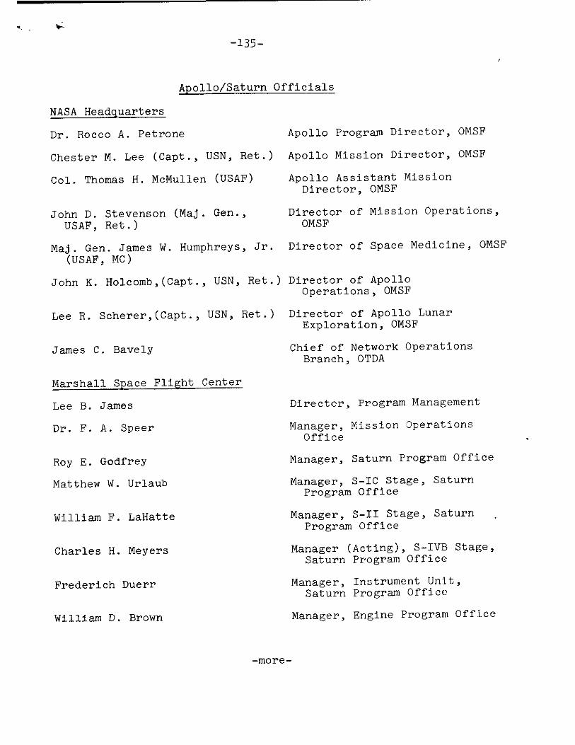
-135-
Apollo/Saturn Officials
NASA Headquarters
Dr. Rocco A. Petrone Apollo Program Director, OMSF
Chester M. Lee (Capt., USN, Ret.) Apollo Mission Director, OMSF
Col. Thomas H. McMullen (USAF) Apollo Assistant Mission Director, OMSF
John D. Stevenson (Maj. Gen., Director of Mission Operations, USAF, Ret.) OMSF
Maj. Gen. James W. Humphreys, Jr. Director of Space Medicine, OMSF (USAF, MC)
John K. Holcomb,(Capt., USN, Ret.) Director of Apollo Operations, OMSF
Lee R. Scherer,(Capt., USN, Ret.) Director of Apollo Lunar Exploration, OMSF
James C. Bavely Chief of Network Operations Branch, OTDA
Marshall Space Flight Center
Lee B. James
Dr. F. A. Speer
Director, Program Management
Manager, Mission Operations Office
Roy E. Godfrey Manager, Saturn Program Office
Matthew W. Urlaub
Manager, S-IC Stage, Saturn Program Office
William F. LaHatte Manager, S-II Stage, Saturn
Program Office
Charles H. Meyers Manager (Acting), S-IVB Stage,
Saturn Program Office
Frederich Duerr Manager, Instrument Unit,
Saturn Program Office
William D. Brown Manager, Engine Program Office
-more-
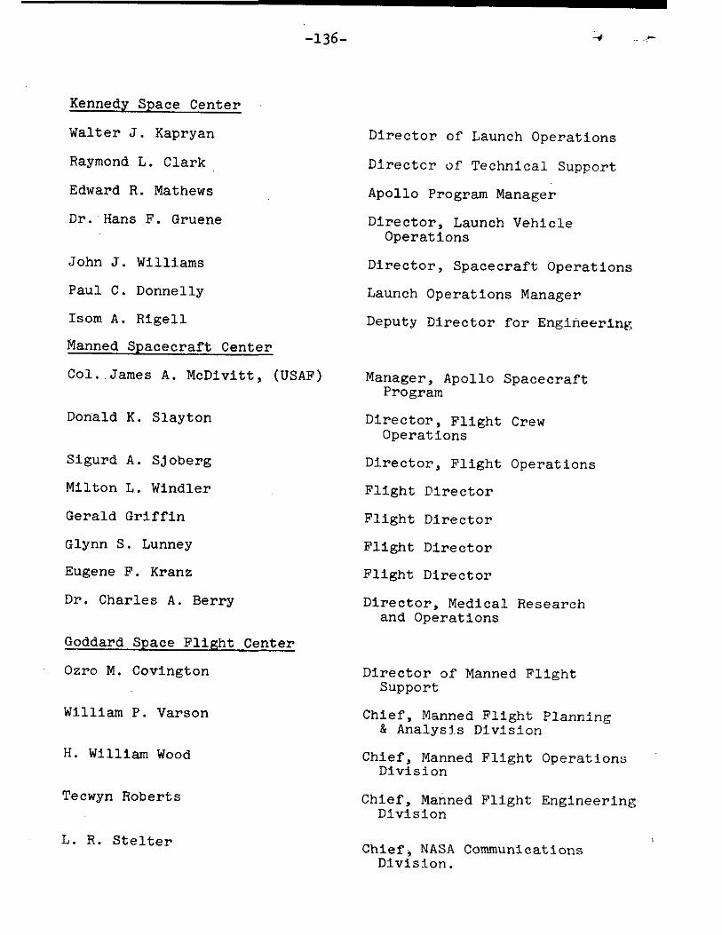
-136-
Kennedy Space Center
Walter J. Kapryan Director of Launch Operations
Raymond L. Clark Director of Technical Support
Edward R. Mathews Apollo Program Manager
Dr. Hans F. Gruene Director, Launch Vehicle Operations
John J. Williams Director, Spacecraft Operations
Paul C. Donnelly Launch Operations Manager
Isom A. Rigell Deputy Director for Engineering
Manned Spacecraft Center
Col. James A. McDivitt, (USAF) Manager, Apollo Spacecraft Program
Donald K. Slayton Director, Flight Crew Operations
Sigurd A. Sjoberg Director, Flight Operations
Milton L. Windler Flight Director
Gerald Griffin Flight Director
Glynn S. Lunney Flight Director
Eugene F. Kranz Flight Director
Dr. Charles A. Berry Director, Medical Research and Operations
Goddard Space Flight Center
Ozro M. Covington
William P. Varson
H. William Wood
Tecwyn Roberts
L. R. Stelter
Director of Manned Flight Support
Chief, Manned Flight Planning & Analysis Division
Chief, Manned Flight Operations Division
Chief, Manned Flight Engineering Division
Chief, NASA Communications Division.
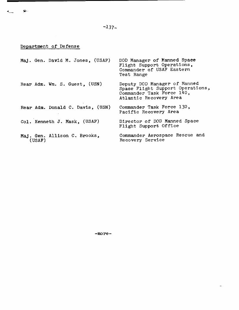
-137-
Department of Defense
Maj. Gen. David M. Jones, (USAF)
Rear Adm. Wm. S. Guest, (USN)
DOD Manager of Manned Space Flight Support Operations, Commander of USAF Eastern Test Range
Deputy DOD Manager of Manned Space Flight Support Operations, Commander Task Force 140, Atlantic Recovery Area
Rear Adm. Donald C. Davis, (USN) Commander Task Force 130, Pacific Recovery Area
Col. Kenneth J. Mask, (USAF) Director of DOD Manned Space Flight Support Office
Maj. Gen. Allison C. Brooks, Commander Aerospace Rescue and (USAF) Recovery Service
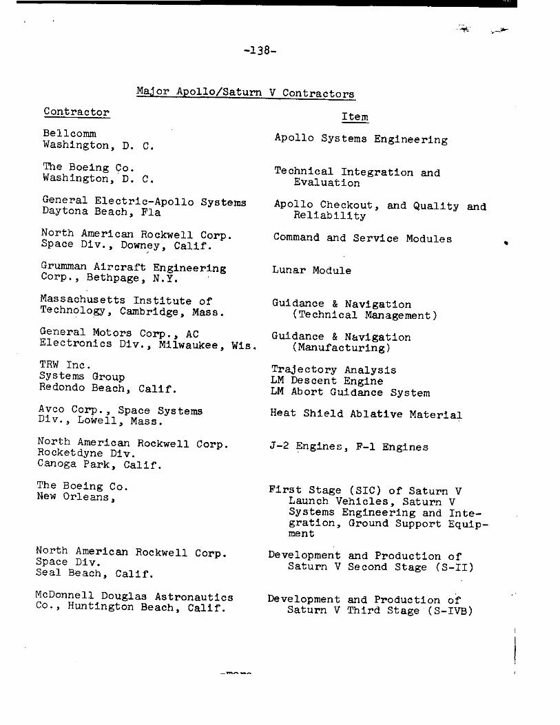
-13 8-
Major Apollo/Saturn V Contractors
Contractor
Item
Bellcomm
Apollo Systems Engineering Washington, D. C.
The Boeing Co. Washington, D. C.
General Electric-Apollo Systems Daytona Beach, Fla
North American Rockwell Corp. Space Div., Downey, Calif.
Grumman Aircraft Engineering Corp., Bethpage, N.Y.
Massachusetts Institute of Technology, Cambridge, Mass.
General Motors Corp., AC Electronics Div., Milwaukee, Wis.
TRW Inc. Systems Group Redondo Beach, Calif.
Avco Corp., Space Systems Div., Lowell, Mass.
North American Rockwell Corp. Rocketdyne Div. Canoga Park, Calif.
The Boeing Co. New Orleans,
North American Rockwell Corp. Space Div. Seal Beach, Calif.
McDonnell Douglas Astronautics Co., Huntington Beach, Calif.
Technical Integration and Evaluation
Apollo Checkout, and Quality and Reliability
Command and Service Modules
Lunar Module
Guidance & Navigation (Technical Management)
Guidance & Navigation (Manufacturing)
Trajectory Analysis LM Descent Engine LM Abort Guidance System
Heat Shield Ablative Material
J-2 Engines, F-1 Engines
First Stage (SIC) of Saturn V Launch Vehicles, Saturn V Systems Engineering and Inte-gration, Ground Support Equip-ment
Development and Production of Saturn V Second Stage (S-II)
Development and Production of Saturn V Third Stage (S-IVB)
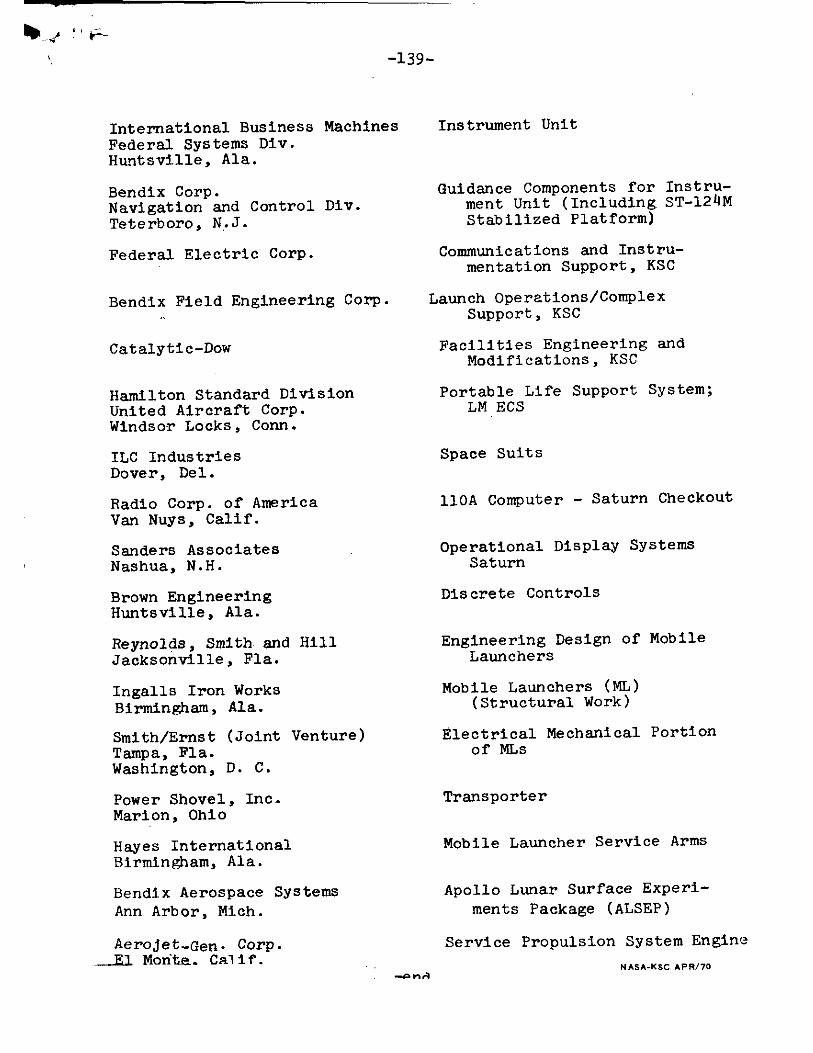
-139-
International Business Machines Federal Systems Div. Huntsville, Ala.
Bendix Corp. Navigation and Control Div. Teterboro, N.J.
Federal Electric Corp.
Bendix Field Engineering Corp.
Catalytic-Dow
Hamilton Standard Division United Aircraft Corp. Windsor Locks, Conn.
ILC Industries Dover, Del.
Radio Corp. of America Van Nuys, Calif.
Sanders Associates Nashua, N.H.
Brown Engineering Huntsville, Ala.
Reynolds, Smith and Hill Jacksonville, Fla.
Ingalls Iron Works Birmingham, Ala.
Smith/Ernst (Joint Venture) Tampa, Fla. Washington, D. C.
Power Shovel, Inc. Marion, Ohio
Hayes International Birmingham, Ala.
Bendix Aerospace Systems Ann Arbor, Mich.
Aerojet-Gen. Corp. E) Morita. Calif .
Instrument Unit
Guidance Components for Instru-ment Unit (Including ST-124M Stabilized Platform)
Communications and Instru-mentation Support, KSC
Launch Operations/Complex Support, KSC
Facilities Engineering and Modifications, KSC
Portable Life Support System; LM ECS
Space Suits
110A Computer - Saturn Checkout
Operational Display Systems Saturn
Discrete Controls
Engineering Design of Mobile Launchers
Mobile Launchers (ML) (Structural Work)
Electrical Mechanical Portion of MLs
Transporter
Mobile Launcher Service Arms
Apollo Lunar Surface Experi-ments Package (ALSEP)
Service Propulsion System Engine
NASA-KSC APR/70