Embed Size (px)
Citation preview
(
/
MINISTRY-.OF AVIATION
R.& M. No. 3172 (20,604)
A.R.C. Technical Report
I
%
AERONAUTICAL RESEARCH COUNCIL REPORTS AND MEMORANDA
The Hydro-elastic Stability of Hydrofoil Struts
By D. V. HILBORNE
LONDON: HER MAJESTY'S STATIONERY OFFICE
x96o PRICE 58. 6d. NET
The-Hydro-elastic Stability of Hydrofoil Struts By D. V. HILBORNE
Reports and Memoranda No. 3z72. November, z958
Summary. Hydrofoil struts, such as might be used for supporting a model in hydrodynamic experiments, are liable to failure through divergence or flutter. This makes the problem of designing a satisfactory strut particularly difficult if high speeds are required and if the struts must be kept thin to avoid cavitation. In the present report the theory developed to describe the aero-elastic stability of aircraft wings is applied to provide predictions of the speeds of onset of the two kinds of instability; in particular a simplified analysis of how the divergence speed depends on strut length and rake is included. The results of a series of experiments on the variation of divergence speed with strut length and on the variations of divergence speed and flutter speed with rake are presented. The agreement between theory and experiment is satisfactory.
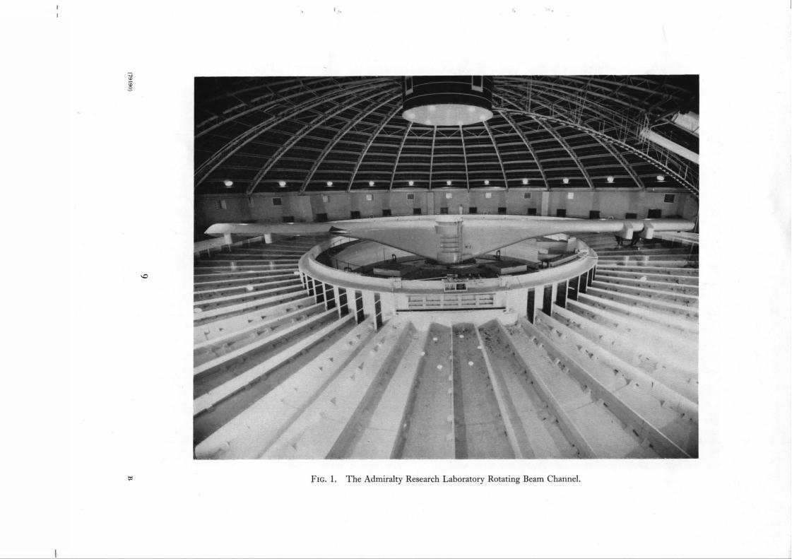
1. Introduction. This work was initiated as a precautionary check on the predicted behaviour
of a large strut designed for supporting models in the 100-ft Rotating Beam Channel at the Admiralty Research Laboratory (see Fig. 1). "
Because of the 'thin section necessary to avoid cavitation at high speed and the need for great
stiffness, this strut(Fig. 2) was made of solid mild steel, weighed five hundredweight when complete,
and would have been extremely dangerous in the event of a serious failure. In view of this it was decided to make a preliminary series of tests on a number of model struts to check estimates of stability, including the effects of length and rake, and determine how much warning of instability could be obtained.
The types of instability encountered are characteristic of elastic lifting surfaces and take one of two forms, known as divergence and flutter. In divergence, conditions are such that small angles of twist increase indefinitely once they have been initiated, and with the type of strut considered this is invariably the form experienced unless preventive steps have been taken. In the case of flutter an
oscillatory motion is developed as a resuk of the interaction of torsion and bending which is initially intermittent, becoming continuous and then growing rapidly if the speed is increased.
2. Theory. The method of estimating divergence speed given below is included as it is felt that a simplified approach of this nature is helpful in clarifying the phenomenon. In the estimation of flutter speed a more general approach is essential and a standard method has been used (Ref. li, which will not be detailed except to mention that in making the calculations a set of coefficients recommended for the purpose in Ref'. (2) was used.
: 2.1. Estimation of Divergence Speed. The following analysis is based on the assumption that the strut "possesses only torsional freedom. This is reasonable if the strut has no rake, since there is then no hydrodynamic coupling between bending and torsion and elastic coupling is negligible in struts of the form considered. The effect of rake can be: allowed-for separately as is shown later.
Admiralty Research Laboratory Report ARL/R1/G/HY/5/3, received 3rd December, 1958.
The equation governing the torsional mot ion of a section of the strut normal to the flexural axis
and distant x from the root is , d20
AO + JO - KO - mo ~ = O,
where all coefficients are positive in sign and assumed to be constant in magnitude (i.e., neglecting
end effects), and
A = torsional inertia/unit length (referred to flexural axis)
0 = torsional deflection
J = hydrodynamic (damping) moment coefficient (referred to the flexural axis)
K = hydrodynamic (static) moment coefficient (referred to the flexural axis)
mo t = torsional stiffness/unit length (referred to the flexural axis).
Separation of the variables gives solutions of the type:
0 = X ( x ) T ( t ) ,
where ,
and T(t) = R e~+ t + S e ~-t
Y
P, Q, R, and S are arbitrary constants and possible values ofp are to be determined from the boundary
conditions.
0 = 0 at the root (x = 0) which is fixed and so Q = 0.
0 = 0 at the tip (x = l) where the load drops to zero and therefore
(n=0,1,2 .) p = ( 2 n + 1 ) ~ / . . .
Divergence will occur if ;t+ is positive, i.e., if K / A > p~',
i.e., if 2 *
7r m o K > ( 2 n + 1) 2. ~ .
Since K = ½pV2c2(dCiv/dO), divergence will occur first as the speed increases in the lowest mode
(n = 0). The divergence speed is given by
I / mo* \
= - dCM • V lc 2p
This is in fact the speed at which the (static) hydrodynamic moment equals the restoring elastic
moment at all points along the strut, i.e.,
. d20 - - K O = mo d x ~ •
2
Since the distribution of twist in the lowest mode is given by 0 = 0m~x sin (½rrx/l), this becomes
K = k~r~rno*/l 2, which also yields the above expression for divergence speed. Assuming the centre of pressure to be at the R-chord position and using an accepted formula
for the first derivative of the lift coefficient:
where A.R. = aspect ratio = I/c
dCz 2~r dO - (1 + 2 / A . R . ) '
dCM 1 dCz ~r dO - 4 dO = 2(1 + 2 c / l ) '
giving
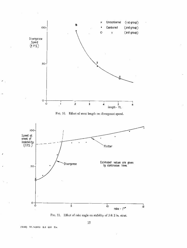
A curve derived from this formula, showing the variation of divergence speed with length, is
shown in Fig. 10.
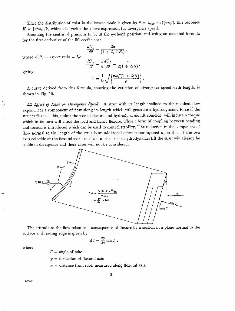
2.2 Effect of Rake on Divergence Speed. A strut with its length inclined to the incident flow
experiences a component of flow along its length which will generate a hydrodynamic force if the
strut is flexed. This, unless the axis of flexure and hydrodynamic lift coincide, will induce a torque
which in its turn will affect the load and hence flexure. Thus a form of coupling between bending
and torsion is introduced which can be used to control stability. The reduction in the component of
flow normal to the length of the strut is an additional effect superimposed upon this. If the two axes coincide or the flexural axis lies ahead of the axis of hydrodynamic lift the strut will already be
stable in divergence and these cases will not be considered.
The attitude to the flow 'taken as a consequence of flexure by a section in a plane normal to the
surface and leading edge is given by
, o=dY tan _P,
where /~ = angle of rake
y = defection of flexural axis
x = distance from root, measured along flexural axis.
{79190)
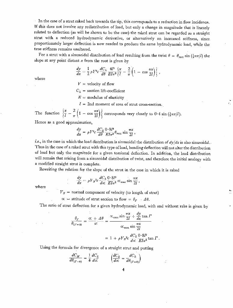
In the case of a strut faked back towards the tip, this corresponds to a reduction in flow incidence.
I f this does not involve any redistribution of load, but only a change in magnitude that is linearly
related to deflection (as will be shown to be the case) the raked strut can be regarded as a straight
strut with a reduced hydrodynamic derivative, or alternatively an increased stiffness, s ince
proportionately larger deflection is now needed to produce the same hydrodynamic load, while the t rue stiffness remains unaltered.
For a strut with a sinusoidal distribution of load resulting from the twist 0 -- 0m~x sin (½7rx/l) the
slope at any point distant x f rom the root is given by
dy 1 dC~ 4l a 2 1 - c o s ~ , dx - 2 P F~c dO EI7r ~ -
where
V = velocity of flow
Cz = section lift-coefficient
E = modulus of elasticity
I = 2nd moment of area of strut cross-section.
The function 2 1 - cos corresponds very closely to 0 .4 sin (½7rx/l).
Hence as a good approximation,
dC z O" 8l 3 *rx dy pV2c sin - - , dx - dO ~ O~x 2l
i.e., in the case in which the load distribution is sinusoidal the distribution of dy /dx is also sinusoidal .
Thus in the case of a raked strut with this type of load, bend!ng deflection will not alter the distribution
of load but only the magnitude for a given torsional deflection. In addition, the load distribution
will remain that arising from a sinusoidal distribution of twist, and therefore the initial analogy with a modified straight strut is complete.
Rewriting the relation fo.r the slope of the strut in the case in which it is raked
where
dy ddCoc z O" 81 ~ . ~rx dx - P V ~ c Ei~r ~ octal,: sm ~ ,
gz¢ = normal component of velocity (to length of strut)
oc = a t t i tude of strut section to flow = O r - A 0.
T h e ratio of strut deflection for a given hydrodynamic load, with and without rake is given by
• "ITX dy Or oc + A 0 OCr~x sin ~ - + dxx tan r '
0(r= 0) oc . 7rx oCma x sin ~ /
= 1 + p Vz¢2c dCz O. 8l 3 doc EIrr ~ t an /~ .
Using the formula for divergence of a straight strut and putting
acl 1 (dc d0(r=o) - ,4 do: ~ ~ - d ~ ]
4
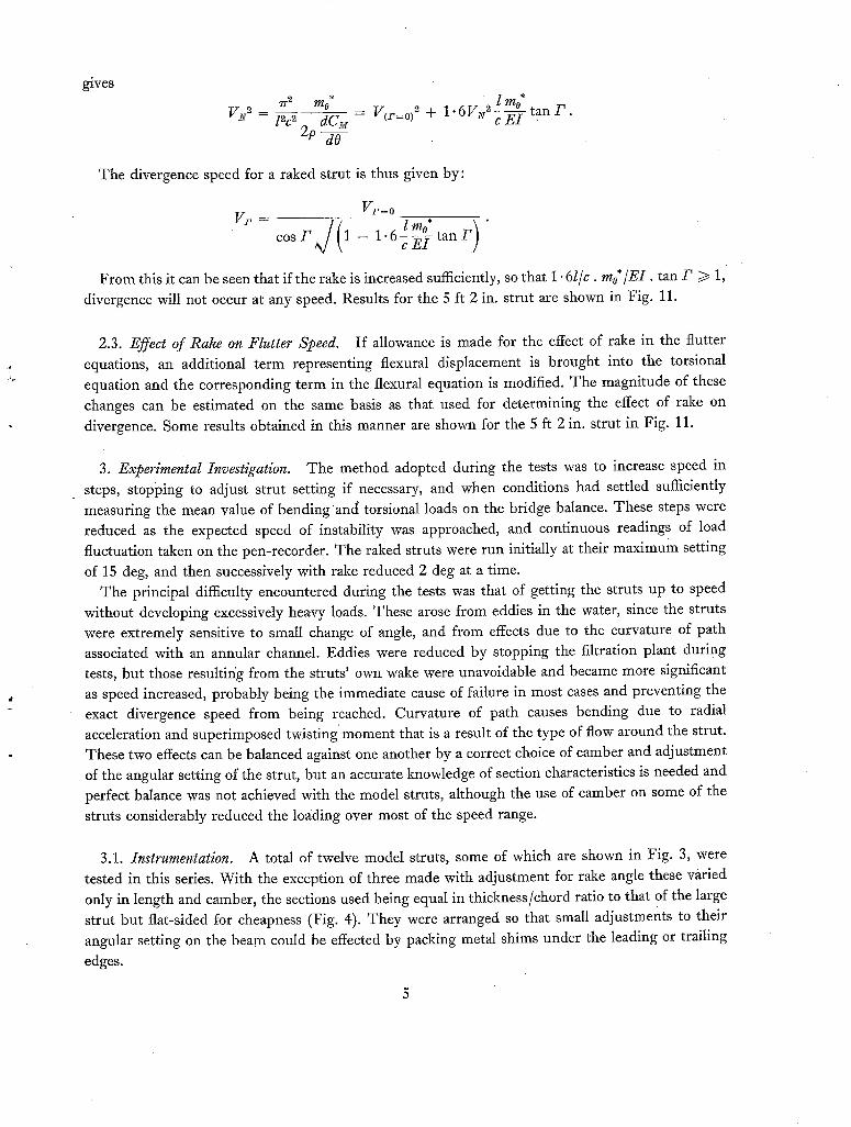
gives ~2 mo* _ l too*
V ~ = l~c ~ dC~ - V(r=°)2 + 1"6VlV2cE7 - t a n / ' "
2p dO
The divergence speed for a raked strut is thus given by:
V~=o l too* F) "
c o s / ~ / ( 1 - 1"6c ~ - t a n
From this it can be seen that if the rake is increased sufficiently, so that 1.61/c. mo*/EI, tan/~/> 1, divergence will not occur at any speed. Results for the 5 ft 2 in. strut are shown in Fig. 11.
2.3. Effect of Rake on Flutter Speed. If allowance is made for the effect of rake in the flutter equations, an additional term representing flexural displacement is brought into the torsional
equation and the corresponding term in the flexural equation is modified. The magnitude of these changes can be estimated on the same basis as that used for determining the effect of rake on
divergence. Some results obtained in this manner are shown for the 5 ft 2 in. strut in Fig. 11.
3. Experimental Investigation. The method adopted during the tests was to increase speed in steps, stopping to adjust strut setting if necessary, and when conditions had settled sufficiently measuring the mean value of bending and torsional loads on the bridge balance. These steps were reduced as the expected speed of instability was approached, and continuous readings of load fluctuation taken on the pen-recorder. The raked struts were run initially at their maximum setting
of 15 deg, and then successively with rake reduced 2 deg at a time. The principal difficulty encountered during the tests was that of getting the struts up to speed
without developing excessively heavy loads. These arose from eddies in the water, since the struts were extremely sensitive to small change of angle, and from effects due to the curvature of path associated with an annular channel. Eddies were reduced by stopping the filtration plant during tests, but those resultir/g from the struts' own wake were unavoidable and became more significant as speed increased, probably being the immediate cause of failure in most cases and preventing the exact divergence speed from being reached. Curvature of path causes bending due to radial acceleration and superimposed twisting moment that is a result of the type of flow around the strut. These two effects can be balanced against one another by a correct choice of camber and adjustment of the angular setting of the strut, but an accurate knowledge of section characteristics is needed and perfect balance was not achieved with the model struts, akhough the use of camber on some of the
struts considerably reduced the loading over most of the speed range.
3.1. Instrumentation. A total of twelve model struts, some of which are shown in Fig. 3, were tested in this series. With the exception of three made with adjustment for rake angle these varied only in length and camber, the sections used being equal in thickness/chord ratio to that of the large strut but flat-sided for cheapness (Fig. 4). They were arranged so that small adjustments to their angular setting on the beam could be effected by packing metal shims under the leading or trailing
edges.
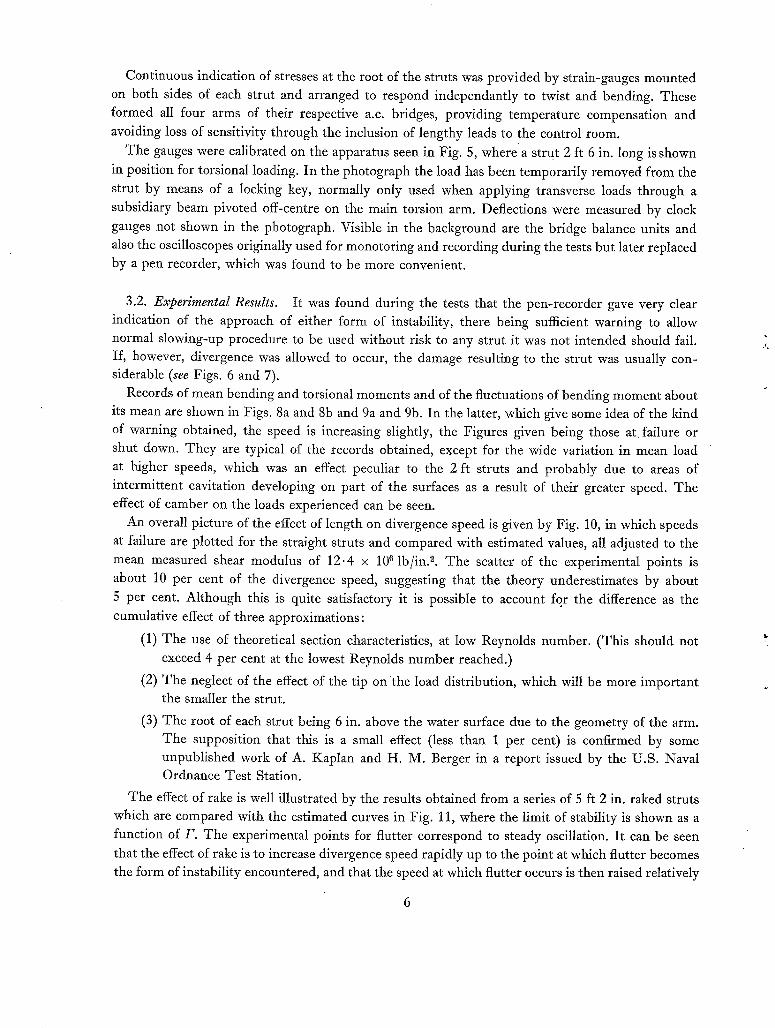
Continuous indication of stresses at the root of the struts was provided by strain-gauges mounted on both sides of each strut and arranged to respond independantly to twist and bending. These formed all four arms of their respective a.c. bridges, providing temperature compensation and
avoiding loss of sensitivity through the inclusion of lengthy leads to the control room.
The gauges were calibrated on the apparatus seen in Fig. 5, where'a strut 2 ft 6 in. long is shown
in position for torsional loading. In the photograph the load has been temporarily removed from the
strut by means of a locking key, normally only used when applying transverse loads through a
subsidiary beam pivoted off-centre on the main torsion arm. Deflections were measured by clock
gauges not shown in the photograph. Visible in the background are the bridge balance units and also the oscilloscopes originally used for monotoring and recording during the tests but later replaced by a pen recorder, which was found to be more convenient.
3.2. Experimental Results. It was found during the tests that the pen-recorder gave very clear indication of the approach of either form of instability, there being sufficient warning to allow normal slowing-up procedure to be used without risk to any strut it was not intended should fail. If, however, divergence was allowed to occur, the damage resulting to the strut was usually con- siderable (see Figs. 6 and 7).
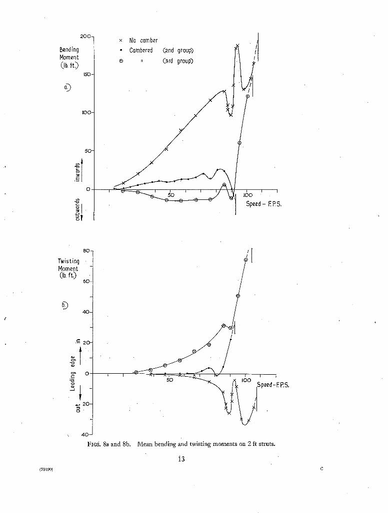
Records of mean bending and torsional moments and of the fluctuations of bending moment about its mean are shown in Figs. 8a and 8b and 9a and 9b. In the latter, which give some idea of the kind of warning obtained, the speed is increasing slightly, the Figures given being those a t failure or shut down. They are typical of the records obtained, except for the wide Variation in mean load at higher speeds, which was an effect peculiar to the 2 ft struts and probably due to areas of intermittent cavitation developing on part of the surfaces as a result of their greater speed. The effect of camber on the loads experienced can be seen.
An overall picture of the effect of length on divergence speed is given by Fig. 10, in which speeds
at failure are plotted for the straight struts and compared with estimated values, all adjusted to the mean measured shear modulus of 12.4 x 10 6 Ib/in. 2. The scatter of the experimental points is
about 10 per cent of the divergence speed, suggesting that the theory underestimates by about
5 per cent. Although this is quite satisfactory it is possible to account for the difference as the cumulative effect of three approximations:
(1) The use of theoretical section characteristics, at low Reynolds number. (This should not exceed 4 per cent at the lowest Reynolds number reached.)
(2) The neglect of the effect of the tip on 'the load distribution, which will be more important the smaller the strut.
(3) The root of each strut being 6 in. above the water surface due to the geometry of the arm. The supposition that this is a small effect (less than 1 per cent) is confirmed by some unpublished work of A. Kaplan and H. M. Berger in a report issued by the U.S. Naval Ordnance Test Station.
The effect of rake is well illustrated by the results obtained from a series of 5 ft 2 in. raked struts which are compared with the estimated curves in Fig. 11, where the limit of stability is shown as a function of F. The experimental points for flutter correspond to steady oscillation. It can be seen that the effect of rake is to increase divergence speed rapidly up to the point at which flutter becomes the form of instability encountered, and that the speed at which flutter occurs is then raised relatively
slowly as F is increased further (over this range the flutter frequency approximately doubled, from 0" 9 to 2.17 c.p.s.). Agreement between experimental and calculated values is good although flutter is over-estimated by about 3 per cent, a relatively small discrepancy in view of the large number of parameters involved.
4. Conclusions. 1. Strain-gauges mounted at the root of a strut provide sufficient warning to guard against unintentional damage in the event of approaching instability of either form.
2. The speed at which a straight strut becomes unstable is strongly influenced by the length, increase in length reducing the speed.
3: The incorporation of rake is a very effective means of delaying the onset of divergence and to a lesser extent flutter, divergence being eliminated altogether if the angle is made large enough.
4. The results show satisfactory agreement with estimates.
Acknowledgements. Acknowledgements are due to Mr. C. T. Wright for the benefit of discussions during the early stages of the work and to Dr. J. Wadsworth for his assistance in the preparation of the tests.
7
A
Cz
c~
E I
K
P,Q,R,S v
C
l
mo n
p t
X
Y 0
P ~+,-
P
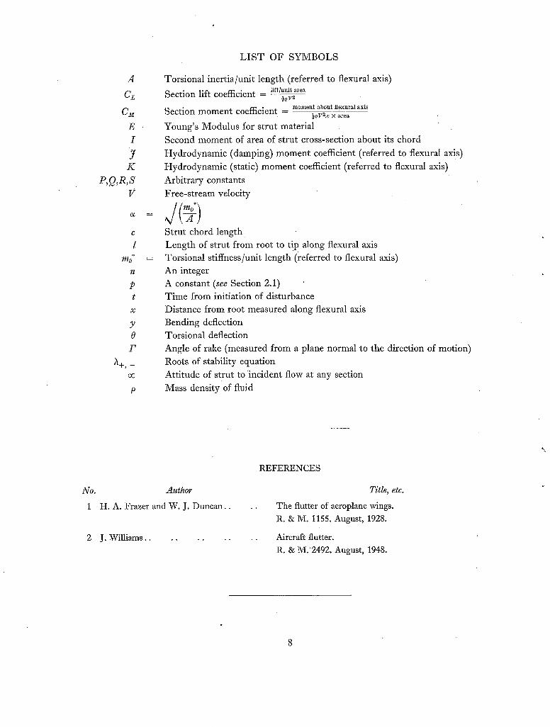
L I S T OF SYMBOLS
Torsional inertia/unit length (referred to flexural axis)
Section lift coefficient - l~r~/~i~.re~
Section moment coefficient momen~ abo~t ~ex, u al axis ~OV~.e x a r e a
Young's Modulus for strut material
Second moment of area of strut cross-section about its chord
Hydrodynamic (damping) moment coefficient (referred to flexural axis )
Hydrodynamic (static) moment coefficient (referred to flexural axis)
Arbitrary constants
Free-stream velocity
\ A ! Strut chord length. Length of strut from root to t!p along flexural axis Torsional stiffness/unit length (referred to flexural axis) An integer A constant (see Section 2.1) Time from initiation of disturbance Distance from root measured along ftexural axis Bending deflection Torsional deflection Angle of rake (measured from a plane normal to the direction of motion) Roots of stability equation Attitude of strut to incident flow at any section
Mass density of fluid
No. Author
1 H.A. Frazer and W. J. Duncan..
2 J. Williams..
REFERENCES
Title, etc.
The flutter of aeroplane wings. R. & M. 1155. August, 1928.
Aircraft flutter. R. & M.2492. August, 1948.
A
i t ,
V
.
~ ~1~ ~ ~ ' ~4
c "i ~ d ~
\
"lp
FIo. 1. The Admiralty Research Laboratory Rotating Beam Channel.

9
T
@
Y
Fie. 2. Full-size strut. FIc. 3. Model struts.
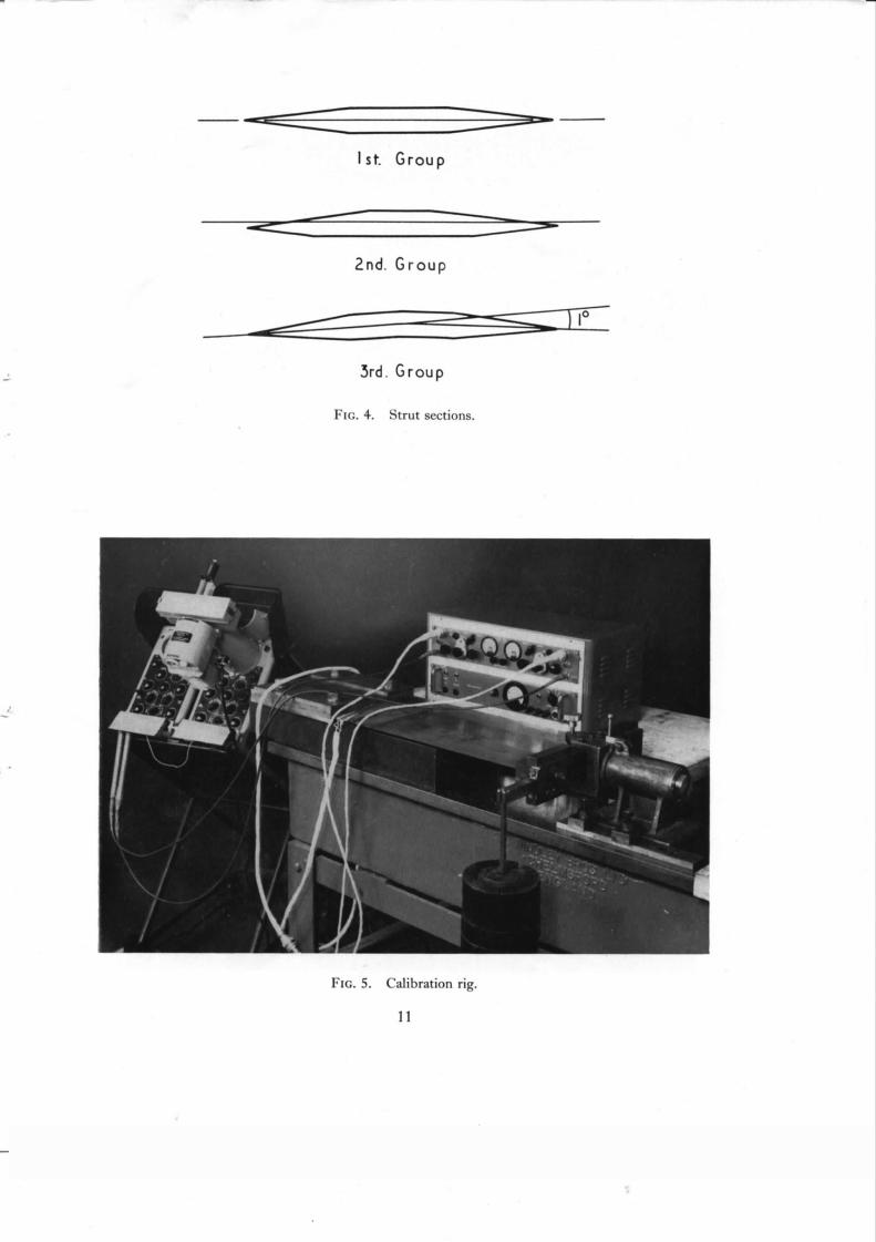
I st. Group
2nd. Group
5rd. Group
FIG. 4. Strut sections.
Fxc. 5. Calibration rig.
11

FIG. 6. 5 ft straight strut after failure.
FIG. 7. 5 ft and two 3 ft 6 in. struts after failure.
12
Bending Moment Oh. fO
© 150 -
X NO comber
CQmbered II
C2nd group)
(3rd group)
I 0 0 -
o i ~ o ; ' , ~ , , I - - ~ ~ ~ / ~1 .00 . Spezd- EP.S.
8 0 -
T w i s t i n g Moment (lb. ft.)
6o
© 4O
--~ 20
.~ 20
4c
FIc.S. 8a and 8b.
/J
, ^ e d ~F.P.S
Mean bending and twisting moments on 2 ft struts.
i3 (79190) C
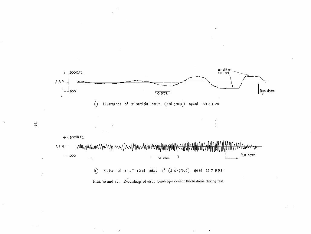
+ ~2oolb.f~t.
~'B'M- t - 200
Ampli fer cut-out ~ , . .
Divergence of 5' straight strut (3rd group) speed 3o.6 EP.S.
R~un down.
+ T2ooIb. ft.
- ± 2 0 0 , r I0 secs. I I ~ Run down.
b~ Flutter of s' 2" strut raked II ° (2nd.group) speed 92.7 F.P.S,
FlOS. 9a and 9b. Recordings of strut bending-moment fluctuations during test.
I00-
Divergence Speed (F. Rs.)
50-
x Uncombered (Istgr0up)
• Cambered (2nd group) ~~k " 0 II (3rd group)
0 I I I I I I
0 I 2 3 4 5 6 length- ft.
FIG. 10. Effect of strut length on divergence speed.
IOO-
Speed at onset of instebility (FPs)
5 0 -
/
. . . . . " Flutter
, ~ ' ~ ' ' D ~ v e r g e n c e Estimated values by continuous lines.
0 I I 0 5
are given
Fm. 11.
IO rake- V ~°
Effect of rake angle on stability of 5 ft 2 in. strut.
15
I 15
( 7 9 1 9 0 ) ~Vt. 5 4 / 8 2 1 0 K . 6 9 / 6 0 H w .
Publications of the Aeronautical Research Council
1941
1942
I943
1944
" 1945 Vol. Vol. Vol.
Vol.
Special VoL
Vol.
Vol.
A N N U A L T E C H N I C A L R E P O R T S O F T H E A E R O N A U T I C A L R E S E A R C H C O U N C I L ( B O U N D V O L U M E S )
Aero and Hydrodynamics, Aerofoils, Airscrews, Engines, Flutter i Stability and Control , Structures. 63s. (post 2s. 3d.)
Vol. I. "Aero and Hydrodynamics, Aerofoils, Airserews, Engines. 75s. (post 2s. 3d.) VoL IL Noise, Parachutes, Stability and Control, Structures, Vibration, Wind Tunnels. 47s. 6d. (post is. 9d.)
Vol. I. Aerodynamics, Aerofoils, Airscrews. 8os. (Post 2s.) Vol. I I . Engines, Flutter, Materials, Parachutes, Performance, Stability and Control, Structures.
9os. (post 2s. 3d.) Vol. I. Aero and Hydrodynamlcs, Acrofoils, Aircraft, Airscrews, Controls. 84s. (post 2s. 6d.) • VoL II . Flutter and Vibration, Materials, Miscellaneous, Navigation, Parachutes, Performance, Plates and)
Panels, Stability, Structures, Test Equipment, Wind Tunnels. 84s. (post 2s. 6d.)
!. Aero and Hydrodynamics, Aerofoils. I3OS. (post 2s. 9d.). II . Aircraft, Airscrews, Controls. 13qs. (post 2s. 9d.)
I I ! . Flutter and Vibration, Instruments, Miscellaneous, Parachutes, Plates and Panels, Propulsion. I3OS. (post 2s. 6d.)
IV. Stability, Structures, Wind Tunnels, Wind Tunnel Technique. I30s. (post 2s. 6d.)
Volumes I. Aero and Hydrodynamics, Aerofoils, Controls, Flutter, Kites, Parachutes, Performance, Propulsion,
Stability. i26s. (post 2s. 6d.) II . Aero and Hydrodynamics, Aerofoils, Airscrews, Controls, Flutter, Materials, Miscellaneous, Parachutes;
Propulsion, Stability, Structures. I47s. (post 2s. 6d.) I I I . Aero and Hydrodynamics, Aerofoils, Airscrews, Controls, Flutter, Kites, Miscellaneous, Parachutes,
Propulsion, Seaplanesi Stability, Structures, Test Equipment. I89S. (post 3s. 3d.)
Reviews of the Aeronautical Research Council I939-48 3s. (post 5d.) 1949-54 5s. (post 6d.)
Index to all Reports and Memoranda published in the Annual Technical Reports I9o9-I9_47 ~ , R. & M. 2600 6s. (post 4d.)
Author Index to the Reports and Memoranda and Current Papers of the Aeronautical Research Council
February, x954-February, I958 R. & M. No..257o (Revised) (Addendum) 7s. 6d. (post 4d.)
I n d e x e s to the Technical Reports of the Aeronautical Research Council July 1, i946-Deccmber 3I, 1946 R. & M. No. 215o IS. 3d. (post 2d.)
k
l P • b l l s h e d Reports and Memoranda of the Between Nos. 2251-2349 R. &
" Between Nos. 2351-2449 - . Between Nos. 2451-2549
• Between Nos. 2551-2649 Between Nos. 2651-2749 Between Nos. 2751-2849 Between Nos. 2851-2949
Aeronautical Research Council M. No. z35o IS. 9d. (post zd.)
R. & M. No. 2450 2s. (post 2d.) R. & M. No. 2550 2s. 6d. (post 2d.) R . & M; No. 2650 zs. 6d. (post 2d.) R. & M. No. 2750 2s. 6d. (post 2d.) R. & M.~No. 2850 2s. 6d. (post zd.) R. & M. No. 2950 3s; (POSt 2d.)
HER MAJESTY'S STATIONERY OFFICE from tile addresses o~erleaf
R. & M. 1~o: 3172
Crown copyright 196o
Printed and published by HER MAJESTY'S STATIONERY OFFICE
To be purchased from York House, Kingsway, London w.c.2
423 Oxford Street, London w.I I3A Castle Street, Edinburgh 2
lO9 St. Mary Street, Cardiff 39 King Street, Manchester 2
Tower Lane, Bristol i 2 Edmund Street, Birmingham 3
80 Chichester Street, Belfast I or through any bookseller
Printed in England
R. & M. No. 3172
S.O. Code No. 23-3172
: i