Embed Size (px)
Citation preview

Figure 1.-The older commercial-type dredge was usually of two-piece construction as clammers felt it tended bottom better. It was also easier to handle overthe side.
RONALD JOEL SMOLOWITZ and VERNON E. NULK
Rear cage
Chain bag
I
Basic Concept Development
The dredge system in use at the timethe choice was made to go to a newsurvey was a 48- inch (122 em) surfacesupplied hydraulic dredge (Fig. 2). Thedredge was of two- piece construction asit was originally built to be handled overthe side. Water was supplied by a 6- inch
maintained with the aid of a shipboarddoppler speed log.
One of the key requirements of thenew survey was to insure that the dredgeused could be operated in a consistentand efficacious manner. This was no simple task considering the various depthsand substrates the survey sampled.
Existing commercial and survey hydraulic clam dredges operate using adeck-mounted pump to supply water tothe dredge via a hose (Fig. 1). The hose,which is 6-10 inches (15.2-25.4 em) indiameter, is assembled in sections, andthe overall length is a function of thedepth being worked. Commercial fishermen have found that the dredge efficiency is significantly affected by supplypressure and volume as well as substratetype. Variations in hose length shouldthen also affect dredge operation.
Towing hawser
.--- Water hose
The authors are with the ortheast FisheriesCenter. National Marine Fisheries Service.
OAA. Woods Hole. MA 02543.
consistent and reliable resource data formanagement purposes. These two trendsstrengthened the need for an improvedstandard survey to measure distributionand production potential of both thesurf clam and ocean quahog stocks.
The experimental design for the newstandard survey consists of performingtows of 5 minutes duration at about 350depth- stratified bu t randomly selectedstations in depths from 18 to 110 m. Atowing speed of 1.5 knots is constantly
ABSTRACT-A clam dredge system, usingan electrically driven submersible pump. wasdesigned for swf clam. Spisula solidissima,and ocean quahog. Arctica islandica. surveysalong the northeast coast ofthe United Statesin wate, deptllS to 100 m. The ].200 kg. 5.2 mlong dredge has a 1.52 m CUlling knife andpumps 7.570 I per minute through the CUllingjet mall/fold. The pump power requirementis 100 amps 01"460 V AC3'phasecurrent provided via a special cable bv the ship:S 150 k Wgenerators. This paper describes the design0/ the dredge and the operating experiencesto date.
Introduction
The Northeast Fisheries Center(NEFC) of the National Marine FisheriesService, formerly the Bureau of Commercial Fisheries, has been conductingclam surveys off the northeastern UnitedStates since 1963. Initially these wereexploratory surveys mostly concernedwith determining the distribution andpotential for commercial utilization ofthe Atlantic surf clam, Spisula solidissima. A variety of vessels, gears, andmethods were used. These surveys alsorevealed that a large ocean quahog,Aretiea islandiea, resource existed in theMiddle Atlantic region between depthsof 40 and 60 m (Murawski and Serchuk,1979).
In 1977 two important trends forced achange in clam survey procedure. ThefIrst was the decline in the surf clampopulations due to intense fishing pressure and a massive natural kill in 1976.These factors increased the pressure onthe deeper ocean quahog beds. Thesecond trend, the direct result of theMagnuson Fishery Management andConservation Act, was the need for more
The Design of an ElectrohydraulicDredge for Clam Surveys
April IWI2. 4414J

I 15'5/1 O.A. !
Figure 2.-An early version of the 48-inch (1.22 m) survey dredge with a V-knife and manifold. Later modificationsincluded a straight blade and manifold and eliminated the chain bag.
centers3/4 '1
1'-'.
Stropping on top not shown -
(1/4" x 1" flat stock on 3" centers)
I
L±'3~r'l~q~ll- -j ,- L~ -------; --1 18 "
II'--
12/1 opron at rear of dredge (1/4" plate)
15/8" hole
---1IC"i48/'-r- ::J(" 7 ~~,J_I, _.~f-_, 1':::::--::'"
X'~- ~: J ::::z= '1, :::::---.,:,/ y'",,= L
--- ::--. 0~!
~ f=i=i=. " - //~}
~I~,L
~ L-2 6"
~~
wall inset l'
2 1/2" LII 48,,---Jl1"I ]) 10'6" ,I
3/4" ;I to support chain bog wall inset 5" 1318 " holes Eyes at
"-'
~~.
""~;:,-
""~.~'"~.

Figure 3.-The 48-inch (1.22 m)survey dredge modified for electrohydraulic operation. The electric cable to the submersible pumpis wrapped with rope for protec-
tion from cuts and abrasion.
(15.2 em) centrifugal pump powered bya 100- horsepower diesel engine mountedon the main deck of the NOAA shipDelaware II.
There were several major operationalproblems with this system. The first wasthat the dredge was depth limited toabout 55 m since its efficiency, due topressure drop in the hose, was decreasedconsiderably at greater depths. Handlingthe long and bulky hose was difficult,especially at the greater depths. Thedredge itself was apparently too light,
Arril/IJ82. 44(4)
1,360 kg, to fish "hard on the bottom"(never leaving contact with the bottom)when towed by the Delaware II undercertain conditions of sea, tide, and depthas evidenced by many "water- hauls"(hauled up completely empty).
The most important consideration wasthat the scientists wanted to sample to110 m, the maximum known extent ofthe commercially important clam beds.The deepest the commercial fleet wasfishing was 55 m and to do that theywere using double hoses attached to
massive pumps and engines built intothe vessels. There was no way this sizeequipment could be added to theDelaware II.
The NEFC had experience with another method of clamming: Electrohydraulic dredging. The first system wasbuilt in 1965 (Standley and Parker, 1967)and was used over the course of the next7 years (Fig. 3). The Delaware II, built in1968, was designed with ample electricpower available to operate the new system. The electrohydraulic dredging
.7

blade was passing in and out of the layerof clams in the substrate, resulting indamaged animals. This problem wasremedied in the new dredge by making itheavier and by better controlling thespeed over bottom by using a dopplerspeed log.
The other cause of cut clams was theblade mounting method. New Jerseycommercial surf c1ammers had foundthat by keeping the blade depressed bythe use of a spring device, this "f1oatingknife" would ride over the dense depositsof clay substrate found in that region.The spring usually consists of a steelspring or a number of rubber bands cutfrom old tire inner tubes. A commercialclammer usually works one geographicregion for a period of time. Thus, headjusts the spring tension to compensatefor different bottom types by continuously observing his catch rate and incidence of cut clams. Due to the natureof the clam surveys, the latter feedbackprocess cannot exist, and thus the bladetension is usually too low or too high. Inthe case of being too low, the blade rides
because of rough bottom encounteredduring random survey tows. The abovefactors evolved into a dredge length of5.2 m, width of 2.13 m. and weight of3.182 kg (Fig. 4 l.
Blade Design
One major problem with the olddredge was the high frequency of cutclams in the catch. Fishermen have traditionally found that their best surf clamcatch rates, with minimum cut clams,was with blade depth (distance betweenbottom of dredge runner and bottom ofblade) set between 5 and 6 inches (12.7and 15.2 em). Blade depth for oceanquahogs is usually less, about 4 inches(10.2 cm). The blade depth on the surveydredges was set at 8 inches (20.3 em) tobe able to assume complete samplingfree of a depth- related bias.
Over the years, two observations weremade relating to the high incidence ofcut clams. In heavy weather or whentowing down current the dredge, asjudged by how the ship handled, wasbouncing along on the bottom; thus the
~Figure 4. - The 60- inch 11.52 m) electrohydraulic dredge in the "dump" position
on the ramp.
method was abandoned when the prototype system began to experience excessive reliability problems. In 1977, afterreviewing these problems. it was decidedthey could be resolved. Since much ofthe electrohydraulic system was usable.and there were signiDcant time andmoney constraints, it was decided tobuild a second generation system puttingthe emphasis on a new dredge design asopposed to a completely new approach.
Meetings were held with clam industryrepresentatives and it was agreed that asurvey dredge would not have to be asefficient as a commercial dredge for eachset of Dshing factors (depth. bottom type.etc.) but that it should be roughly basedon an industry- type design that could berelated to the industry as far as catchingefficiency. Ideally, the dredge needed tobe a consistent sampler. The operationaldesign problem was stated as follows: Toinsure the dredge rides squarely on thebottom with blade fully cutting over aknown distance and to have the entirecatch within the desired size-selectionrange retained.
Dredge Design
This paper is primarily concerned withthe mechanical design of the electrohydraulic dredge. Details of the electricalsystem can be found in Crossen andSmolowitz (1980).
The first decision made on the dredgedesign was to increase its size. comparedwith the old dredge, to increase thesample size collected and dredge weight.A choice of a 152.4 cm (60-inch) widecutting blade was made, since anythingwider would not Dt up the stern ramp ofthe Delaware II and this size was common commercially in the event thatcomparison Dshing experiments wouldbe conducted. For the same reason otherdredge characteristics, such as bar spacing, were kept similar to industry designs.
It was decided to construct the dredgeas one piece to aid in midwater stabilityand stern docking and undocking (somedredges still are of two- piece construction). The forward section of the dredgewas designed to contain the electricallydriven submersible pump. Manifold toblade edge distance and cage volumefollowed industry practice. However, thedredge structure was built extra strong
4 Marine Fisheries Review

up in hard compact sands, in manyinstances cutting right through the clambearing layer, causing cuts. When theblade tension is too high, the consequence is filling the dredge with clayand/or heavy sediments, thus cloggingthe dredge early in the tow. It was foundduring clam surveys that. in general, thehigher the spring tension the better thecatch rate.
To eliminate any doubt about variations in cutting depth due to blade movement, it was decided to fish the newsurvey dredge normally with the bladellxed securely 20 em below the runners.The capability to "float" the blade wasstill retained. During a routine survey,consisting of about 300 random stations.the blade gets badly "rim- racked" severaltimes due to large rocks or obstructions.A door was provided on the top of thedredge to facilitate removal and replacement of the blade assembly and manifold; the whole job requires about anhour. During exploratory fishing onknown "hard" bottom the blade has beenspring mounted and has sustained virtually no damage.
Many fishermen feel that keeping theblade edge or "knife" sharp improves theefficiency of the dredge. During the normal course of towing the knife edge getsconsiderably dented by small rocks. Onthe new dredge, as with many industrydredges, the knife edge is a separatepiece of plow steel bolted onto the bladeassembly and is readily replaceable.
One other design consideration wasthe location of the blade assembly. Theblade was located close to the midpointof the longitudinal axis. as many commercial fishermen feel this placementimproves bottom- tending characteristics.
Cage Design
The cage of the old survey dredge,which was built by a commercial dredgemaker in 1965, was constructed of 1- inchwide (2.54 em) flat bar welded between\12- inch (1.27 em) diameter rods leaving34-inch (1.9 em) spacing between. Without the flat bar the dredge would havehad the 2.5-inch (6.35 em) spacing,almost standard throughout the commercial surf clam fleet.
While the commercial fishem1an isprimarily interested in retaining surf
April 1982. 44r4j
clams greater than 5 inches (12.7 em),the scientist needs a complete sample ofclams down to 2 inches (5.1 em). Thecatch of "prerecruit" clams is used toassess the overall clam population as anaid in determining future harvest.
The problem with decreasing thespacing in the dredge cage is that thedredge tends to clog up rapidly in mostsubstrates. If the dredge does clog beforethe tow is completed. it effectively stopsfishing, thus giving a biased sample.
One of the fIrst considerations indesigning the cage was to build it similarto a commercial dredge hut with largescantlings to increase weight and ruggedness. The top and sides of the cagewere constructed of %- inch (1.6 em)diameter round stock placed 2%-inches(6.7 em) on center. The bottom of thecage was constructed sloping upwardstowards the aft end, the entire bottombeing higher than the runners. The 3kinch (1.9 em) round stock forming thebottom was alternately staggered in twolayers spaced 23kinches (7.0 em) aparton centers when measured diagonally.Commercial fishermen claim this methodof construction allows the trash andsediment to wash out more efficiently.In addition, round vs. flat constructionmaterials are believed to provide betterflushing action.
The next step was to line the entirecage with a removable liner. The commercial boats fishing for ocean quahogs,a smaller clam than the surf clam, linetheir surf clam dredges with wire mesh.with anywhere from 1.5- to 2.5- inch(3.8-6.4 em) openings. usually squaremesh. The new survey dredge was firstlined with 1X I-inch (2.54 cm2
) vinylcoated wire (14-gauge) mesh becausethat would give 100 percent retention of2-inch (5.1 em) clams. However, subsequent field tests, described later in thispaper, indicated rapid clogging, so theliner was enlarged to 2x2-inch (5.1 cm2
)
II-gauge mesh.The cage is also equipped with several
hatches or doors. The entire aft end ofthe dredge cage is hinged to swing openand dump the entire contents over theship's stern. This "trash door" is usuallyused if the dredge is filled with rocks orclay.
The rearmost section of the cage bot-
tom is a catch removal door hinged at itsaftermost end. The door is opened bymeans of a lever mounted on the dredgeside. The aft end of the cage, with thetrash door, is tapered at an angle so thatwhen the dredge is sitting in the sternramp the aft end is vertical. This facilitates dumping the catch.
Manifold Assembly
The manifold on the new surveydredge is a bolt-on unit capable of beingpositioned at different distances from theblade. There are 14 cutting nozzles madeof 3kinch (1.90 em) diameter, 6-inch(15.2 em) long pipe nipples angled at45° to the vertical facing aft. In additionthere are two "blowbacks" connected byhose to the blade assembly. The 6-inch(15.2 em) diameter inlet to the manifoldcan either be connected to the dredgemounted submersible pump or to a hosefrom a surface supply.
Submersible Pump Mount
The submersible pump is mountedonto the dredge with the suction endfacing forward. It is bolted into a cradlealong the dredge centerline and protected on the bottom by a 1- inch (2.54em) thick steel plate. The suction issurrounded by steel plate except for thetop section which is covered by a screen.The openings in the screen (12 mm) aresmaller than the inside nozzle diameterto prevent gravel from entering andblocking the nozzles. A guard made ofsteel bar is bolted on over the pump.
To enable the pump to be located inthis position. it was necessary to tow thedredge using a bridle arrangement. Aheavy steel bar is incorporated into thedredge frame on both sides of the forward part of the dredge with holes forbridle attachment. There are also accommodations made to mount an odometer and counterweight in this part ofthe dredge.
Operation
The dredge is set and hauled from astern ramp using a I-inch (2.54 em) steelwire rope from the main trawl winch.Once the dredge is on the bottom, a2-inch (5.1 em) polypropylene rope connected between the dredge and the shiptakes over the load to pull the dredge

.. J~qiiA!i/
/1t,"'- / I'
..:i ./ :/----/-:-','------i-\--TOWing hawser Strength member termination
~~ f/,i------'.:-\-\-_- Haulback wire conn
l
ector ~.>~··~~1'~ / "'-.,,- ..... power coble __~ __/;~- A' ~\- .. l '-..___ ------- //
\~.'.1 _.._.~~_~--::::..-o"" __~.~~~ -~--.
'-------Knife
Figure 5,-The dredge is towed by the towing hawser. the hauling wire is kept slack, and the power cable has about1.500 pounds tension,
along the bottom for the tow duration(Fig,S). The elasticity of the polypropylene provides a built-in shock absorber.Also, both the steel cable and the plasticrope act as backups for each other. Atthe same time the dredge is set or hauled,an operator at the electric cable winch iscontrolling the amount of cable out.During the tow the winch maintains apreset tension on the cable, generally onthe order of 1,500 pounds.
The ramp assembly used to carry thedredge aboard the vessel is a 43- foot(13.1 m) long, 8,700-pound (3,955 kg)structure primarily of 10- inch (25.4 cm)vertical "H" beams forming rails 6 feet(1.8 m) apart. Its lower end is set into thestem ramp of the vessel and rises forward
6
at a 30° incline to a height of 15 feet (4.6m). The lower section of the ramp, 13feet (4.0 m) long. pivots at water level toenable docking and alignment of thedredge prior to retrieval. Once the dredgeis properly aligned, it is hauled to the topof the incline, at which time the catchdoor in the rear underside of the dredgeis opened. allowing the catch to be emptied into a sorting table beneath the ramp(Fig. 6).
Extensive use is made of a dopplerspeed log to maintain a constant towingspeed over the bottom of 1.5 knotsthroughout the 5- minute standard surveytow. Comparisons made using a loran-Cplotter and actual diver measurementsof the dredge path connrm that the actual
tow lengths are standardized within theconfidence limits required for assessmentpurposes.
Diver observations indicate that thedredge fIshes "hard" on the bottom,cutting a uniform trench for the fulllength of the tow. This is connrmed bycatch analysis showing few cut clams.
Clam Dredge Testing
The Delaware II was outfItted withthe electrohydraulic clam system duringa cruise from 13 to 22 August 1979. Oneof the main objectives of the trip was tocollect data on the efficiency and selectivity of the system in catching clamswhen it was fIshed in a research surveymode. A similar cruise had been con-
Marine Fisheries Reviell'

L.W-L
Hauling wire
leading totrawl winchr-------~----
Hauling wire to
trawl winch
Submersible electric pump
Sorting tableHydraulic ram
Towing hawser to winch --- -
~~iFlFl~~= ----r- -=----7.:::-1-------- , )F===~~~~1::::::::::J
Hanging block Deck block Cable winch
Roller \ ==::b::::=========~1====~~guide '--'=' Winch hydraulic
\ - power pack
Cableblock
I
I
HANDLING PROCEDURE
Docking ramp with JlV" guide at top -----.
Selling'Ii) The Winch is payed oul and Ihe Dredgeslides down Ihe Ramp. The Docking Ramp isin a closed position.I ii) The Docking Ramp is opened and Ihewire, caplured in the "V", slides inlo the Sheave.
Hauling Back:( i ) The Dredge is hauled up and nosed intothe Docking Ramp.Iii) The Docking Romp is closed as haulbackconlinues, bringing Dredge aboard.(iii) The Dredge is hauled 10 the top of IheRamp and the Bollom Trapdoor opened dumping Calch on the Sorting Table.riv) The Trap Door is closed and the Dredgeis ready 10 set again.
Figure 6.-Stern chute clam dredge ramp used aboard the Delaware II.
ducted in the past using the old survey Table 1. - Tow summary for Delaware /I Cruise 79-08, 13·22 Augusl 1979.
dredge, some of the results of which are TowPosilion
Depth Tow PositionDeplh
described in Meyer et al. (1981), no. Lat. Long. 1m) Remarks no. Lat. Long. 1m) Remarks
Seventy-seven tows were made, 10 of 1 40 0 53'N 72°09.5'W 27 35 39°25.5'N 74°11.8'W 182- Marked clam 36 39°23.3'N 74°18.0'W 11
them observed by divers, along the south 17 400 25'N 72°23.6'W 55 area 37 39°34.5'N 74°12.5'W 9
coast of long Island, N.Y., and along the 18 400 45.6'N 72°39.6'W 18 38 39°35.0'N 74°12.8'W 719 400 46.9'N 72°36.2'W 18 39 39°37.4'N 74°1O.5'W 11 Packed w/clay
New Jersey coast south to Atlantic City 20 40°50.1 'N 72°25.2'W 18 40 400 33.0'N 73°50.0'W 9 Divers' survey
(Table 1). 21 40 0 50.5'N 72°23.1 'W 18 path22 400 50.5'N 72°23.1 'W 18 Divers' survey 41 400 33.5'N 73°51.0'W 7
path 42 400 33.3'N 73°51.0'W 7 Divers' ride23 400 51.7'N 72°21.5'W 16 Divers' film dredge
Diver Dredge Observations dredge 43 400 33.0'N 73°50.0'W 9 Divers' survey24 400 44.9'N 72°40.1 'W 24 path
The following is a summary of some25 39°16.2'N 740 20.4'W 16 44 400 33.0'N 73°50.0'W 926 39°19.0'N 74°20.7'W 15 45 400 33.8'N 73°43.0'W 11
of the information provided by diver 27 39°19.3'N 74°16.2'W 15 46 400 34.3'N 73°41.7'W 928 39°17.2'N 74°28.5'W 13 47 400 34.6'N 73°31.8'W 9
observation: 29 39°25.8'N 74°12.0'W 18 48 400 36.9'N 73°15.9'W 9
1) There than sufficient 30 39°25.4'N 74 0 11.9'W 16 Divers' survey 49 400 36.9'N 73°13.9'W 13was more palh 50 40°37.1 'N 73°1O.9'W 16water flow from the pump for proper 31 39°25.5'N 74°11.8'W 18 51· Marked clam
digging action of the nozzles. At slow32 39°23.7'N 74°11.0'W 18 77 400 25'N 72°23.6'W 55 area33 39°25.5'N 74°11.8'W 18 78 400 56.0'N 72°11.0'W 16 Divers' film
speeds, up to 1 knot, the jets dug deeper 34 39°25.5'N 74°11.8'W 18 dredge
April/WI2.4414) 7

'Mention of trade names or commercial firmsdoes not imply endorsement by the NationalMarine Fisheries Service, NOAA.
201.86 327.00 36386 564255563 132.61 13439 1429821.03 59.30 5079 50.25
15980 208.40 26228 462.67243.92 445.60 465.44 66583
Table 2.-Catch dala (number of clams) from test tows.
Tow no. Catch Tow no. Catch Tow no. Catch Tow no. Catch
51 169 58 456 63 144 70 57152 104 59 316 64 392 71 51353 231 60 354 65 489 72 51854 261 61 400 66 272 73 414
55 178 62 109 67 550 74 52356 215 68 343 75 56457 255 69 357 76 898
77 513
than the blade. However, path surveysdidn't show any clams being blown underthe blade or deep into the cut path.Cutting depth was in inverse function ofdredge speed.
2) In abnormally dense clam beds offRockaway Beach, N.Y. many small clamswere found in the first 15 m of each towpath. This may indicate selection throughthe blade assembly.
3) The 2.5 cm square lined dredgetended to fill rapidly, in most test areasbefore the first 75 m of the tow. Uponfilling, the dredge still dug, but bleweverything to the sides and no longersampled properly.
4) No flushing was observed out of thetop or sides of the dredge. Flushing tookplace through the bottom and rear panels.
5) The dredge towed much easier(lower engine rpm required) with thepump on.
Video Taping
A Sub-sea Systems CM-40' underwater color television camera was usedto document the dredge in operation.The camera was used in three modes:Diver held, dredge mounted, and surface
Tow no. Catch
2 1313 1204 1455 403
6 1297 1988 3629 152
10 35211 30712 29313 353
14 37815 28016 17617 155
X= 24588SD= 104.12SE= 26.03
±2SE= 1938229794
lowered. Lighting was provided by two250-watt lights mounted on the camerahousing. AlSO m long multiconductorcable provided for the video signals,camera power, lighting, and diver communications. The cable was handled ondeck using a hand- powered winch with14 sliprings.
The video and audio signals weremonitored on the surface with a lVC 33cm color TV monitor (Model No. 4280m) and recorded on video tape with alVC color portable video cassette recorder (Model No. HR-410DA).
Five hours of video tape were madeon the operation of the cutting nozzlesand the blade and of the flushing actionof the dredge cage at various speeds.The lowering of a camera in areas previously dredged enabled inspections of thedredged trenches.
Substrate Testing
It is generally believed that bottomtype significantly affects clam dredgeoperations. During this cruise a preliminary attempt was made to classify thedifferent substrates. To this end, thefollowing test equipment (manufacturedby Soiltest, Inc.) was used:
1) Pocket penetrometer (CL-7000)with 2.54 cm diameter adapter foot(CL-701),
2) Torvane torsional vane shear device
lCL-600 with sensitIve vane adapter(CL-602. 0.0-0.2 TSF range),
3) Sand grading chart (A- 17).The hardest sand encountered by the
divers was on tow station 33. The diverscollected a sample using a large coffeecan as a corer and brought it up to thesurface for analysis. The sample wasclassified as coarse sand, subroundedwith granules having a penetration of0.047 kg/cm
2and a shear of 0.008
kg/cm2
• The dredge had no trouble cutting through this substrate.
Main Winch Tension Test
A hydraulic load cell was attached tothe deck haulback block to provide adirect reading of the tension on the mainwire.
Maximum tensions during haulbacksaveraged about 10,000-13,000 poundswith brief peak loads up to 17,000pounds. At tow station 39. when thedredge was fully on board, the winchstalled at about 18,000 pounds of tension.After the dredge was flushed of some ofits catch, it was able to be hauled aboard.
Operating Parameters
Of the 77 tows, 43 were made primarily in an attempt to recover previouslymarked clams in a small area that seemedto have a relatively uniform distributionof ocean quahogs. We took advantage ofthis by varying operating parameters todetermine what effects, if any, they hadon catch rate (Table 2).
Tow Stations 2-J7
Scope was varied from 1.6: 1 to 3: 1with no apparent effect. The length oftow was also varied from 3 to 15 minuteswith no apparent effect on catch rates.These observations were probably dueto the dredge filling rapidly and then justacting as a plow. Catches from tows 2- 17varied from 120 to 403 clams, the averagebeing 246 clams. During tow 16 thedredge was operated with the pump offand caught 176 clams. The mesh sizethroughout these stations was 2.54 cm
2•
Tow Stations 51-77
Tow stations 51 -77 were all fIshed at aconstant speed (1.5 knots), scope (2:1),and duration (5 minutes).
On tows 51- 57 the pump was not
Marine Ft:~heries Rel,iell'

Table 3.-Path survey results from three stations in the same area occupied on Delaware 1/ Cruise 79-08,13-22August 1979.
Tow no. Tows 33and 34
Observation or measurement 31 33 34 combined
Path length 61 m 58m 56 mWidth 1.52 m 1.52m 1.52 m -Path area 92.72 m' 83.16 m' 85.12 m' 173.28 m'
Dredge catch (A) 106 93 82 175Surface catch (B) 12 (9 damaged) 20 (9 damaged) 4 (3 damaged) 24
Path samples catch (0.25 m') 1,0,0,0,0,0 1, 29-0's 30-0's 1, 59-0'sDensity of pathg clams remaining 0.66 clams/m 2 0.13 clams/m' 0 0.067 clams/m'Total patch clams remaining (e) 61 12 0 11.55
Outside sampies catch (0.25 m') 2,1,1,1,8-o's 1,1,1,1,1,25-0's 2,1,1,27-0's 2,7-1 's 52-0'sDensity of outside clams 1.66 clams/m' 0.66 clams/m' 0.53 clams/m' 0.60 clams/m'Total clams in patch before
tow based on grid densities (D) 154 58 45 104
Total clams found in path 179 125 86 210.5(Ai-B+C=E)
Efficiency based on (D) 688% 1600% 182.2% 1683%Efficiency based on (E) 59.2% 744% 953% 831%
1)
turned on until the dredge was on thebottom and strain was placed on thetowing hawser. The average catch was202 clams. On tows 58-62 the pump wasturned on before the dredge hit thebottom. The average catch increased to327 clams. This technique probably allowed the dredge to fish a little longerbefore filling up and thus was used on allsubsequent tows.
On tows 63- 69 the rear mesh panelwas changed to 5.1 cm square mesh.The average catch for these tows increased to 364 clams. On tows 70-77 therear bottom panel mesh was alsochanged to 5.1 cm2 mesh and the averagecatch increased to 564 clams per tow.This indicates. along with diver observations, that most of the washing action,and probably selection, occurs on thedredge's bottom.
Throughout the above tests, despitethe mesh size modifications, the sizedistribution of the clams retained didnot appreciably change. A possible explanation for the lack of differentialselectivity is that shell, sand, and liveinvertebrates may have clogged thedredge at the beginning of the tows,negating further filtering ability (Murawski et aI., 1980). Actually, as seen by theoverall change in catch rates, there apparently was a change in fIltering abilitybut not enough to influence selectivityin this test area and for the populationsize/structure present.
Path Surveys
Divers conducted detailed surveys onsix dredge paths. The procedure usedwas as follows: The ship set the dredge,with a buoy attached, heading downcurrent and anchored up on the dredge.The divers, tended from a Zodiac rubberboat, descended to the dredge andmarked the starting point with an anchorand buoy. In addition, they placed a reelof marked (leaded) line on the bottomand attached one end to the rear of thedredge. When they were ready theymoved clear of the dredge and signaledthe surface to start the tow. The shipturned the pump on and commencedtowing. Using a Northstar loranC/EPSCO plotter, a doppler speed log,and an estimate of the distance betweenthe dredge buoy and anchor buoy, the
April /982. 44(4)
ship towed long enough to make a 50 mpath. Upon completion of the tow. thepump was stopped and the ship anchored-up on the dredge.
After the pump was shut off, the diversread the lead line to get the path length.They then proceeded down the pathcollecting any clams on the surface inthe dredge area.
Using 0.25 m2 grid squares, they tookrandom samples both inside and outsidethe path.
Table 3 presents the results from threepath surveys made in the same area offthe coast of Brigantine, N.J., in 18 m ofwater.
Due to the small number of clamsfound during tow number 31 by diversampling, we increased the sampling intows 33 and 34 to 30 grid samples insideand 30 grid samples outside the paths.The data from tows 33 and 34 were thencombined and the standard error of thegrid samples was calculated to find the95 percent confidence limits. Using theselimits, the efficiency based on the dredgecatch divided by the total clams found inthe path (E) was calculated to lie between74.9 and 87.9 percent of X = 83.1 percent, which is reasonable. However, in asimilar manner, the efficiency based onoutside the path grid densities (D), liesbetween 100.1 and 529.7 percent or X =168.3 percent, which is too high. Theseresults make both efficiency calculationssuspect, possibly indicating insufficient
sampling or diver undersampling. Oneother possibility is that clam distributionsare spotty in nature and the assumptionthat clam density to either side of thepath is similar to that within the path,is wrong within our limited samplingregime.
Discussion
Clamming, regardless of the species,area. or method, simply involves diggingthrough substrate and gathering clams.Research on soft-shell clams. Mya arenaria, has shown that efficiency (percentremovals) and breakage (mortality onclams remaining) using hand- harvestingtechniques is a function of the fIsherman's skill and method (Medcof andMacPhail, 1952, 1967; Dow et aI., 1954;Glude, 1954). Improvements in efficiency, nearing 100 percent, and reductionsin breakage came about with the introduction of hydraulic escalator dredgesinto this fishery (Dickie and MacPhail.1957; Manning. 1957. 1960; MacPhail.1961; Medcof. 1961). As with handmethods, the efficiency and effects ofhydraulic dredging are highly variabledepending on location, bottom type.clam density, gear design, weather, andoperator skill. The long- term effects ofan indirect nature, such as sedimentclouds covering the bottom or sand particles damaging the animals, have beenhard to observe and document.
Hand methods of clamming, such as

raking and tonging, were used in the surfclam fIshery (Parker, 1971) and are stillused in the inshore quahog, Mercenariamercenaria, fIshery. In the 1920's, towednonhydraulic dredges, or "dry" dredging,came into use in these fIsheries but notwithout controversy which still existstoday. Glude and Landers (1953) compared the effects of hand raking andpower dredging and found no biologicalbasis for restricting either method offtshing.
In the surf clam fIshery, developmentcontinued on into hydraulic dredgingdue to the increased efficiency (Parker.1971) and the fact that dry dredgingcrushed surf clams (Ruggiero. 1961).Medcof and Caddy (1971 ) found that askillfully controlled hydraulic dredge wasclose to 100 percent efficient in catchingocean quahogs. In comparison theyfound a dry dredge less than I percentefficient and broke the shells of 80 percent of the uncaught clams.
Experiments conducted with the oldNEFC hydraulic survey dredge gave results similar to those reported above:Efficiency that could approach 100 percent (Meyer et aI., 1981). Efficiency, inboth studies, was found to be a functionof towing speed. scope, and the relationship between cutting blade and hydraulic nozzles. Observations of the survey dredge proved that, once the dredgefIlled, efficiency dropped to zero andthe dredge became a tool of destructionalong the bottom.
Testing of the new electrohydraulicsurvey dredge, some of which has beenreported in this paper, indicates that thisdredge can also be highly efficient. Ananalysis of 10 tows in the marked quahogarea indicates that less than 3 percent ofthe catch suffered cuts due to dredgingaction. The question arises about how adredge can be fIne-tuned to maximizeits efficiency and minimize destructiveeffects. To answer this question requiresan understanding of the exact mechanism, or functional principle, of dredgeoperation.
One of the first clues on how a hydraulic dredge works was observed by Medcofand MacPhail 11964) during development of a hydraulic rake to harvest softshell clams. Using laboratory aquaria andfteld tests, they determined that the
/11
hydraulic nozzles, or water jets, wereconverting the clam- bearing substratefrom a solid to a fluid state: A slurry.The clams, being less dense that theslurry. become buoyant and pop up tothe slurry surface. Based on this observation they presumed there was a largeamount of tolerance in the design of thehydraulic system as long as the fluidizingfunction was maintained.
The slurring action is a function ofwater jet volume, pressure, and flow, aswell as dredge speed. Diver observationsby Medcof and Caddy (1971), conftrmedby our divers during fteld tests, showthat when the dredge is towed too slowlyfor a given set of hydraulic parameters,the slurring action becomes an excavating action, digging a trench deeper thanthe "cutting" blade of the dredge. Correspondingly, when the dredge is towedtoo fast, it either comes out of the bottomor rapidly ftlls with substrate and performs a "plowing" action.
During the efficiency tests conductedwith the new survey dredge, the diversmade some general observations of bottom hardness using their hands. On hardsand bottom before the dredge made apass they could barely get their fingersto penetrate, but after the dredge passedthey could stick their entire arm up tothe elbows into the substrate in thedredge track.
Robert Frost, of the clammer WandoRiver out of Warren. R.1.. heard of thisobservation and realized the clams wouldtend to float up out of the fluidizedbottom. He decided to modify his 60inch (1.52 m) hydraulic ocean quahogdredge to make use of this principle. Heincreased his hydraulic manifold- toblade-distance to 48 inches (1.2 m),increased the water flow, and decreasedthe blade depth to 3 cm. Towing between2 and 3 knots he almost doubled hiscatch rate. Making use of a flow meterand remote pressure gauge, Frost foundthat at his towing speeds his greatestcatch rates occu rred at 50 gpm (190Ipm) per inch (2.54 cm) of blade width.Realizing that speed is a critical factor,Frost plans to purchase a $14,000 doppler speed log to improve his operation.
Frost's increased catch rate does notmean that his dredge efficiency, as measured by percent removal. has increased.
What may be happening is that cloggingdue to substrate ftlling the dredge hasdecreased, and that with the increase inspeed the dredge is effectively ftshing agreater area of bottom before it ftlls andplows. This may be economically efficient for a commercial operation, but isnot desirable for a survey mode.
Knowing that there is a relationshipbetween towing speed and water volumethat can change and still permit 100percent dredge efficiency, allows for newdesign considerations. In the electrohydraulic dredge operation, if the watervolume requirement can be cut signifIcantly, at whatever sacriftce in towingspeed, the initial system cost would dropconsiderably and reliability would begreatly enhanced.
A better understanding of the "bedfluidization" requirements of the clamharvesting process is needed. This, inturn, could be used to improve manifold/nozzle design, an area of high fluid"losses" in both commercial surfacesupplied dredges and the electrohydraulic dredge. Improvements in this areaalone probably would result in signiftcantenergy savings to the commercial clamindustry.
Acknowledgments
The authors would like to thank JohnHuguenin for his help during the technical review of the manuscript and JohnLamont for the illustrations.
Literature Cited
Crossen.J. M.. and R. J. Smolowitz. 1980. Powersystem requiremenls of an eleclrohydraulicclam dredge. /11 Mar. Technol.l\O. p. 4]]-4]8.Mar. Technol. Soc.
Dickie.l. M.. and J. S. MacPhail. 19:;7. An experimental mechanical shelilish-digger. Fish.Res. BoanJ Can .. All. Prog. Rep. 66:]-9.
Dow. R. L.. D. E. Wallace. and L. N. Taxiarchis.IlJ:'4. Clam IMm arel1aria) breakage inMaine. Maine Dep. Sea Shore Fish .. Res.Bull. I:'.] p.
Glude. J. B. IlJ:;4. Survival of soft-shell clams.Ml'O arenoria. buried at various depths. MaineDep. Sea Shore Fish .. Res. Bull. 22.26 p.
_-=-_ .and W. S. Landers. 195]. Biologicalelfecls on hard clams of hand raking and power dredging. U.S. Dep. Inler.. Spec. Sci. Rep.Fish. 110.42 p.
MacPhail. J. S. 1% I. A hydraulic escalatorshellflsh harvester. Bull. Fish. Res. BoardCan. 121\.24 p.
Manning. J. H. IlJ57. The Maryland soft-shellclam industry and ilS effecls on tidewater resources. Md. Dep. Res. Educ.. Resour. StudyRep. I1. 2:' p.
Marine Fisheries Rel'ie\\'

___ . 1%0. Commercial and biologicaluses of the Maryland soft clam dredge. Proc.Gulf Caribb. Fish. Inst .. 12:61-67.
Medcof. J. C. 1% I. Effect of hydraulic escalator harvester on undersize soft-shell clams.1959 Proc. Natl. Shellfish. Assoc. 50: 151-161.
___ . and J. F. Caddy. 1971. Underwaterobservations and performance of clam dredgesof three types. ICES C.M. 1971/B:IO. 7 p.
___ . and J. S. MacPhail. 1952. Break-age - the bug- bear in clam handling. Fish.Res. Board Can .. Prog. Rep. IAtl.1 54:)Y-25.
___ . and . 19M. A new hy-draulic rake for softshell clams. 1%2 Proc.Natl. ShellfJsh. Assoc. 5]: 11-] I.
Dredge Hydraulics
If the new information available indicates that water volume requirementscan be decreased, then the use of a surface supply to the new survey dredgeneeds to be reconsidered. At the sametime it would be interesting to theoretically examine the head losses due to themanifold/nozzle design and see if thisarrangement can be improved. In thissection we are going to compare a surface to a submersible-supplied systemunder today's operating conditions, toprovide a starting point for future workin the above areas.
Standley and Parker (1967), during thedevelopment of the first electrohydraulic dredge, instrumented for pressureand flow both surface-supplied and submersible pump operations. They presented the following data for the surfacepump:
Length of hose (L) = 250 ftDiameter of hose (D) = 0.5 ft
Flow (Q) gpmCase I 1,475Case II 1,825
Pressure difference (f::"p) psiCase I 17Case II 27
Using this data we can calculate theroughness height ( E ) for the clam hose.
April 1982. 44(4)
_-,-----_ .and . IY67. FishingeffJ-ciency of clam hacks and mortalities incidental to fJshing. 1964 Proc. Natl. ShellfJsh.Assoc. 55:5]-72.
Meyer. T. L.. R. A. Cooper. and K. J. Pecci.19HI. The performance and environmentaleffects of a hydralic clam dredge. Mar. Fish.Rev. 4]19):14-22.
Murawski. S. A.. J. W. Ropes. and F. M. Serchuk. IYHO. Growth studies of the ocean quahog. Aretica islandica. ICES C.M. 1980/K:]H. 24 p.
___ . and F. M. Serchuk. 1979. Distribution. size composition. and relative abundance of ocean quahog. Arctica islandica.
Appendix A
Case IDischarge Q= 1,475 gal/min
xlminx~60 sec 7.46 gal
= 3.295 fe/sec
Velocity V= ~
2 (1)2 2A = rrr = rr 4 0.19636 ft
3.295V=0.19636 = 16.7812 ft/sec
Using the Darcy- Weisbach equationL V2
h,= f{j 2g ,
. 2 144 in2h,= head loss = f::"p = 17 Ib/m x~f
1 t1 fe
X 64 Ib = 38.25 ftwater
substituting to solve for friction factor f(38.25) (32.2) _
(250) (281.608) f - 0.0175.
Using the Moody diagram fromStreeter (1966),f= 0.0175, VD" = 100.68, and
ED =0.0005,
roughness height E is 0.00025 foot.
Case II
Q = 1,825 gal/min = 4.077 fe/secQ 4.077
V= A = 0.19636 = 20.76 ft/sec
h, = 27 Ib/ in2 = 60.75 ft water
populations off the middle Atlantic coast ofthe United States. ICES C.M. 19791K:26. 22 p.
Parker. P. S. 1971. History and development ofsurf clam harvesting gear. U.S. Dep. Commer.. NOAA Tech. Rep. NMFS Circ. ]64.15 p.
Ruggiero. M. 1961. Equipment Note No. 9The surf-clam fJshery of New Jersey. Commer. Fish. Rev. 23(8): 11-13.
Standley. M. L.. and P. S. Parker. 1967. Development of a submersible pumping system fora hydraulic surf clam dredge. Com mer. Fish.Rev. 29(6):50-55.
Streeter. V. L. 1966. Fluid mechanics. McGrawHill. 705 p.
substituting into the Darcy- Weisbachequation,
_ (250) (20.76)260.75 - f (0.5) (2) (32.2)
f= 0.0182VD' I = 124.58
from Moody diagram TI = 0.006
thus E = 0.0003 ft.
From the results of these two cases wewill assume that the roughness heightfor the clam hose is 0.00028 foot. Thisis a composite roughness height whichtakes into account minor losses createdby hose fittings, etc.
Goodyear Rubber Company, one ofthe manufacturers of rubber clam hose,has standard loss charts that give thehead loss for 6-inch diameter rubberhose as 8.8 psi per 100 feet of hose at1,800 gpm. This works out to a roughness height of 0.00015 foot.Thus 8.8 Ib/in2
X 2.5 = 22.0 Ib/in2headloss for 250 ft,
h = 22 00 Ib/' 2 144 in2
1 feor I • m X 2 X1 ft 64 Ib
= 49.5 ftwa,er'As expected this theoretical head loss of49.5 feet is lower than the Case II headloss of 60.75 feet. The difference is possibly due to "minor losses" caused by thecatenary the hose takes while beingtowed as well as the hose fittings. Actually the so-called minor losses can be
/I

KD K = 2 elbows = 1.90Le = f 1 swing check = 2.50
K,o,al = 4.40
642R= 5.42 f(
4.4 (0.66)Le =-~= 16U3 ft
(O.OIR) (182.3) (13.07)2Hs, - - 0.66(64) = 13.27 ft
0.5V2
Hse = entrance head loss =~ = 1.33 ft
Total suction losses = 32.27 f!water (14.2 psi)
Discharge losses:4.47
Vd = 0.19636 = 22.76 ft/sec
(Vd2
- V/l 22.762- 13.072
Hdv -
QVs AQ = 2,000 gpm = 4.47 fe/sec, Ds
= 8", r = 4" = 0.33'A =1T/ 1=0.342ft2
Vs = 13.07 ft/secHss = static head loss = 15 ft
V2
Hsv = velocity head loss = 2R
= 136~72 = 2.67 ft
. . (Ls+ Lel (Vsl2
Hs, = fnctlonal losses = f Ds
(2R)
Ls = suction line length = 21 ftDs = inside diameter = 0.66 ftLe = equivalent length due to
"minor losses"f = friction factor = 0.018
Surface Supply Loss Calculations
Suction losses (see Fig. A-l):
highly significant in the clamming operation.
For the comparison of the surface vs.submersible supply systems we chose tolook at an operating depth of 300 feet;the maximum limit of the commercialsize clam populations now known. Usingtwo to one scope this will involve hoselengths of 600 feet. We chose 2,000 gpmas the flow rate as this is about the lowerindustry limit for 6O-inch dredges.
Specific gravity is about 1.025 for seawater, but for the purposes of this discussion we will neglect it, as it will havelittle significance on these calculations.
-8/1
6/1 hose---~/
Hose couplingsevery 50 I typicol ----II
/Screen
L.WL.(::--=:...--:...-=-..-- r--- .....I 1,.-\ \
I ( I II 1 \ L_/I I"....I 1 I 1"-..., --! 1 (/' /, '/
-------~:~~----------------
Bottom
Figure A-I.-Schematic of surface-supplied clam dredge system.
/2 Marine Fisheries Review
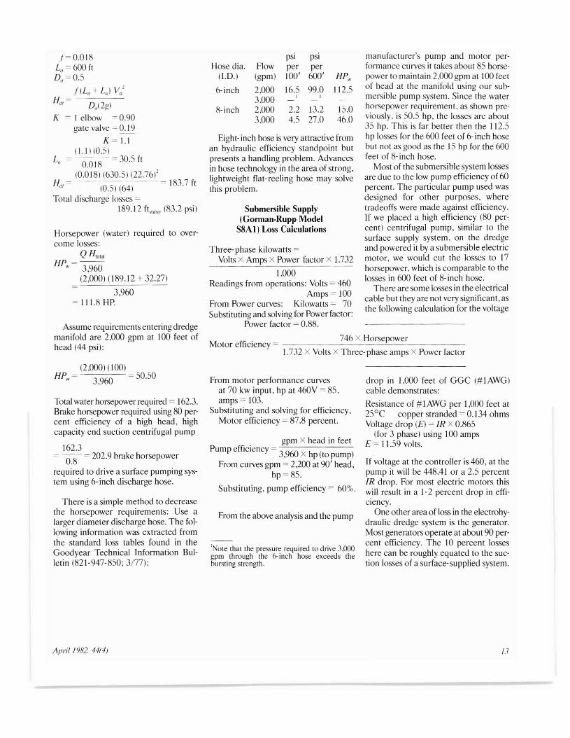
manufacturer's pump and motor perfonnance curves it takes about 85 horsepower to maintain 2,000 gpm at 100 feetof head at the manifold using our submersible pump system. Since the waterhorsepower requirement. as shown previously. is 50.5 hp, the losses are about35 hp. This is far better then the I 12.5hp losses for the 600 feet of 6- inch hosebut not as good as the 15 hp for the 600feet of 8- inch hose.
Most of the submersible system lossesare due to the low pump efficiency of 60percent. The particular pump used wasdesigned for other purposes, wheretradeoffs were made against efficiency.If we placed a high efficiency (80 percent) centrifugal pump, similar to thesurface supply system, on the dredgeand powered it by a submersible electricmotor, we would cut the losses to 17horsepower, which is comparable to thelosses in 600 feet of 8-inch hose.
There are some losses in the electricalcable but they are not very significant, asthe following calculation for the voltage
psi psiHose dia. Flow per per
(I.D.) (gpm) 100' 600' HPw
6-inch 2,000 16.5 99.0 112.53,000
, ,8-inch 2,000 2.2 13.2 15.0
3,000 4.5 27.0 46.0
Submersible Supply(Gorman-Rupp Model
S8A1) Loss Calculations
746 x HorsepowerMotor efficiency = -----------'-----------
1.732 X Volts X Three-phase amps X Power factor
Eight-inch hose is very attractive froman hydraulic efficiency standpoint butpresents a handling problem. Advancesin hose technology in the area of strong,lightweight flat- reeling hose may solvethis problem.
Three-phase kilowatts =Volts x Amps x Power factor X 1.732
1,000Readings from operations: Volts = 460
Amps= 100From Power curves: Kilowatts = 70Substituting and solving for Power factor:
Power factor = 0.88.Assume requirements entering dredgemanifold are 2,000 gpm at 100 feet ofhead (44 psi):
Horsepower (water) required to overcome losses:
QH'o'a'HPw = 3,960
(2,000) (189.12 + 32.27)
3,960= I I 1.8 HP.
f= 0.018Ld = 600 ftDd =O.5
flLd + Le ) Vd
1
Hd,= Dd (2g)
K = I elbow = 0.90gate valve = 0.19
K = 1.l(1.1 )(0.5)
0.018 =30.5ft
(0.018) (630.5) (22.76)2Hd, = - (0.5) (64) = 183.7 ft
Total discharge losses =189.12 ftwa,er (83.2 psi)
(2,000) (100)HPw = 3,960 = 50.50
Total water horsepower required = 162.3.Brake horsepower required using 80 percent efficiency of a high head, highcapacity end suction centrifugal pump
162.3= ---o.s = 202.9 brake horsepower
required to drive a surface pumping system using 6- inch discharge hose.
There is a simple method to decreasethe horsepower requirements: Use alarger diameter discharge hose. The following infonnation was extracted fromthe standard loss tables found in theGoodyear Technical Infonnation Bulletin (821-947-850; 3177):
From motor perfonnance curvesat 70 kw input, hp at 460V = 85,amps = 103.
Substituting and solving for efficiency,Motor efficiency = 87.8 percent.
gpm X head in feetPump efficiency = 3 960 X h ( ), p topump
From curves gpm = 2,200 at 90' head,hp = 85.
Substituting, pump efficiency = 60%.
From the above analysis and the pump
'Note that the pressure required to drive 3,000gpm through the 6-inch hose exceeds thebursting strength.
drop in 1,000 feet of GGC (# I AWG)cable demonstrates:
Resistance of # I AWG per 1,000 feet at25°C copper stranded = 0.134 ohmsVoltage drop (E) = IR X 0.865
(for 3 phase) using 100 ampsE = 11.59 volts.
If voltage at the controller is 460, at thepump it will be 448.41 or a 2.5 percentIR drop. For most electric motors thiswill result in a 1-2 percent drop in efficiency.
One other area of loss in the electrohydraulic dredge system is the generator.Most generators operate at about 90 percent efficiency. The 10 percent losseshere can be roughly equated to the suction losses of a surface-supplied system.
April 1982. 44(4) 13

~
Appendix B
•E
Top bors removed this side --lmrcw~y E a
[B-1J
13"
12"
---.l
-L6 1/2"
T36"
8-5}
b. Manifold Mount (dwg 8-4)
c. Hinged Ponel (dwg 8-5)
d. Padeye (dwg 8 -5 )
6_, .. ,,,, I -.L J
~16"l..~c l
fl25" I
86 25r-:LfF1~~=::j l=l~U
25"
IL
198" I _-----.J__---=~~~JJI
..c-_~ ~D .' d r341/
2" I~ . ~u~~__ I l14'/" --L-~~~.L-
• 2~"rod"Js
E~
3
Lu 1= 'i')§§!~ +1la5; ~ 6')', 30,,-l-39,,----l--34,,-----J--35 1/2" . ,
l..~D
r-
3"6
3"
lClJ~~.
~~
~
~.
§'~.
s:

~":J~
~I.D~eet
1" X 3" Solid flat
I~
12m 0 1 2 3 4 5 6),,1,' ,I I I I' ,
. 6''1l~
(
8 rC T PumpMuuni. . -------.11/2 solid rd ~~~~~~~~~ ~~__ ~__,,,2 ,"" cd 2 ,"" cd I ___ __ .,... /dwg 8 51I j 1'1'- wdcd I I -:--1.-:.. ..1W wl,d cd I, I I , " ~ , I \\ 3 d
I " - " ~ '.\ wI" ""
I - , "I , _ \
\ i,--' S
N S"liun A-A~ (dWg 8-5!
-'CR;
~.::::-
} n
}o
11/4 " nom sch
80 pipe, 2" Ig
70 req
11/4 " solid rd
72" long, 2 req
Ln1112"dlo I
~h~, ~D:
I m I
o I I' :I' ,, J
, ,, '-
1-.- k ~
Detail K Blade HingeMount {3/8" plote J
h = 15/16
I = 31/s"
j = 2 3/4"
k = 3 1/2"
L = 3"
m = 71/2"
a = 15/s"
b 13/4
c = 3"
d = 114"
e = 2"f 31/4"
g = 3/4"
Inches
Details I, J, K (enlarged view)
024 6 8 ~ QI, I, ,,!, I I I, I ,.! I
g g
'I r~ --j r®n~ ,hJ m: 2
.tr~catch)
end
Door Releose PadsDetOil J
~':;}e_
f, n 0I j---,- - --- . - - - .
Detail ITrash Door Hinge
£l.
~tl'--i I~ IQ c IQ 'N L :"...L,
0: df~1''"
plan
Views E-E
Catch Door
2"solid rd
III 69"lg
11/2"-111solid rd
r' 1
63" N ~I
_LJ
Section D-D
5/8" solid rounds
Lspace~,~" between
3/4 " solid roundsspaced 2" between
(diagonally measured)
1" ~,~~"-;-"-;-~.J.;:\-,,-;-,-;-,I
5~/ ~iew B-Br-- - l/j'~ ~ash Door
11" x12" solid flat
-'-"1

-'"
I B-3 1
9/16" drill thru
2 holeS in each
of 4 uprights
M4"x54#/ft
11===_c~':.ellM '
15 3/8"
! 22 3/4"
o I ' 21/2" 4 1/4"0-,-
•
1314 "
,~ [3/8" plate6112" gusset
.-.1 TYP--i----'
Section L-L
7" nom sch 40 pipe
2 pcs 10" long-
Side members are 1/2" x 4"
flat stock
@ Note. Blade is 7/2" x 3" Single bevel flat blade steel
Qm 0 1 2 3N" ! " ' I I I
~P
Blade Frame (portion)
Section P-P
---66"----
1-1 1/4" drill
I through
Section M-M( enlarged view)
r---1" x 3" Flat stock ~h 59112" _P--;- ~
'7'I,r-~ rL
I __ \,':.3
Washer from 3/8" plate
13/4" 0 D, 1" I. 0
\'~
1 14' UTlL-c- 3 1/2" TYP
13112" 13' ni~ ~/2' TYP
LJ3"i
(l)~'- --<>~; 4 5 /16"
Illf I11/2" -.; }/79°
3 pc stops
fabricated from
3/8" plate
/11/4" nom
sch 80
pipe
\~4 verfJcal
I ~~~~~~~~~~~~~YJb!=~=!::~!=!:::!-!:::fIJ members are~ 1"x4" flat
518" rd stack stock
r-------"'----' '" / '""L r r "'{ Do not weld In
I 61 " I lthese carners
J2V'~uu 1 L- l~ REF
L-20 " I 18 7/8" I 20,,----l
I 11116" 60" Blade @
~~.~
~;:,~
~.v,
~"~'"

:to"2::::.:
18-41
Side View
71/16" drill thru 8 holes
evenly spaced
NOTE All stock is 3/8"unless otherwise
specified
",,,,---{
~
8 1/4" boll Circle
3/4" plate flange, and
cover, are 10" d'Gmeter
r7/8" dnll thru
2 holes each end
of manifold
~Ni
-24"------1 l__ 653/8" . _
HOLD ,----'----------,
Q~ 0 1 2 3N!"I"I,,!,,! I ! !
---31"-- - - --r N
·---62"-----------
rIl
H-22"
o I 0
16"1'--
it" ( ;v+-'YII C~J-~2" _L!1!_3"...j
I- "-~ I--- 15/16
End View
"Threadolet"
welded fiffing
size t2-6 x 3/4"
r 6" nom sch 80 pipeI
i
1~11/4"
r6" nom "Tube Tum"
/1seamless steel short
, radIUs elbow
53/4" 0 D rd. mechanical
tubing 120 wall th
'"
.J 3"
-I 31/2" I--j-JNOTE Add 43/4" l /-A I Fl/ /straight 6" nom rpipe extension J r
1" diG. dflJl thr;;1 P ""\ 1\for each of 16 'I ( ;'1"-" , '
"Threodolets" A \...---r \>- 7" round
y-- I 230 \2 4 6 8 10 12 ~
?"I!!!!!II!!!!I!!d!!;!!!!!!!!II!!I!t II !!!!I!!r
(L
~ Manifold Mountrr-r--\f=c=~=!=!1~r0LI DETAIL G ~End~ 13 " 1:111/16" View
, _ /16dnll
I spacers ~ 5"J ~ :~ru~,holes2 1 radIUs16" ,~--1"d'_..J. nil thru
-~....~~
inches Section N-N ( End View) Section 0-0 ( Plan) Section R-R ( Plan)
-"

00
o'"f;)I
~.~"'
IB-51
, 5/S" radius-----~/
Top-Hinged Panel
HinqedetaJ!
- 11/4" x 3/S" flat stack
2"diadrill thru
3" radius
Towing Eye
l1/z" radius
Blade Hold Down PadeyeDetail U
Ii.r-N
~
l1/z" drill thru
12,,, 10 9 8 7 6 5 4 3 Z 1 a 1, ! , "I
3/4" TYP 3 gussets
\t 2 outside gusse,tsare one piece eo"center is two pc
3"x 3"solid r--6V2"l-, 4
7/ "Jbar REF"'\ --f2'7/8"~
·Jfi~~ "': I 1"'1"' IL--L---J 21/8" radiUS
3 5/8"
C::&.~
liz" x 1"x 2" black
Pump Mount
w- r<l
liZ " plate
20"--f+-141/2"
4 x 138#/ft
1 x3 REF 1/Z" bash plate REF~
2"-1 1---163/8"
1_, HOLD
••.~ ~4" I'1" ~ I I -<3D' 93/4"li 6112'[ ~
12 in a 1 2 3 flIII,,'!""'! I I !
~S(1)
~;,(1)
~.
8'""~':s: