Embed Size (px)
Citation preview
UNLIMITED DISTRIBUTION
I* National Defence Defense nationaleResearch and Bureau de rechercheDevelopment Branch et d6veloppement
TECHNICAL MEMORANDUM 921/209March 1992
AD-A249 886
CROSS SECTIONAL CONSTANTS ANDSTRESS DISTRIBUTIONS OF
THIN-WALLED SECTIONS
Thomas S.Z. Hu
DTIQIECTEAT14 IMB*
Defence CentrG, deResearch Recherches pour laEstablishment DefenseAtlantic ~ ~ 'Atlantique
Canad~i92-12794CU II n 113I UcII
UNLIMITED DISTRIBUTION
I * National Defence Defense nationaleResearch and Bureau de rechercheDevelopment Branch et developpement
CROSS SECTIONAL CONSTANTS ANDSTRESS DISTRIBUTIONS OF
THIN-WALLED SECTIONS
Thomas S.Z. Hu
March 1992
Approved by R.T. Schmitke Distribution Approved byDirector / Technology Division
Director / Technology Division
TECHNICAL MEMORANDUM 92/209
Defence Centre deResearch f. Recherches pour laEstablishment Defense
Atlantic ; Atlantique
Canad'i

Abstract
The equivalent beam model is widely used for predicting strength and vibrationof a ship hull in a preliminary analysis. It can also be used for checking results in a largefinite element model and for parametric studies of ship behaviour. This method treats aship hull as a series of prismatic segments connected together. Each segment has itssectional properties, real and virtual masses. The program SCRAP was developed atDefence Research Establishment Atlantic for calculation of cross sectional constants andestimation of mass properties. It prepares input data files for the finite element programsVAST and TORSON and interprets the analytical results. SCRAP can be only used forsome specific sections at the present time. For arbitrarily oriented sections it may give anincorrect shear centre and warping constant and thus the wrong stress distributions.
This report presents the mathematical derivations of the equations used for thecalculation of cross sectional constants and stress distributions of thin-walled sections. Asan improvement over the current SCRAP program, these equations are applicable to anyshape of cross section, both open and closed, and are independent of the orientation ofthe cross section. A computer-oriented step-by-step procedure based on these equationsis outlined. Several examples are also presented to verify the procedure.
Resume
Dans une analyse prrliminaire, le module de poutre dquivalente est largementutilis6 pour la prevision de la rdsistance et des vibrations d'une coque de navire. I1 peutaussi Etre utilis6 pour vdrifier les rrsultats dans un module A 616ments finis de grandedimension et dans des dtudes paramdtriques sur la tenue des navires. Dans la presentemrthode, on consid~re qu'une coque de navire est constitute d'une sdrie de segmentsprismatiques relids ensemble. Chaque segment poss~de ses proprirtfs de section, sa masserrelle et sa masse virtuelle. Le programme SCRAP a 6t6 6crit au Centre de recherchespour la defense (Atlantique) en vue du calcul des constantes de section transversale et del'estimation des propridtrs de masse. I1 prepare les fichiers d'entrfe pour les programmesA 616ments finis VAST et TORSON et il interpr~te les rrsultats analytiques. SCRAP nepeut pour le moment Etre utilisd que pour certaines sections particulires. Dans le cas desections d'orientation arbitraire, il peut donner une constante de centre de cisaillement etde gauchissement erron~e et, par consdquent, des distributions de contraintes erronfes.
Ce rapport montre comment on a drduit les dquations mathrmatiques utilis~es pourcalculer les constantes de section transversale et 6tablir les distributions de contraintes dessections A pario mince. Ces 6quations constituent un perfectionnement par rapport auprogramme SCRAP actuel : elles peuvent ftre appliqures A toutes les formes de sectiontransversale, ouvertes et fermres, et elles sont indrpendantes de l'orientation de la sectiontranseversale. On drcrit une mrthode pas A pas mrcanisre basre sur ces 6quations.Plusieure exemples permettant de verifier la mdthode sont aussi prrsentfs.
ii
Contents
Abstract ii
Table of Contents ii.
List of Figures iv
Notations v
1. Introduction 1
2. Derivations 2
2.1 General Considerations 2
2.2 Pure Bending 4
2.3 Twisting 8
3. Numerical Procedure 12
4. Examples 17
5. Concluding Remarks 27
Appendix A - St-Venant Torsion 28
Appendix B - Open Section - Example 30
References 33
Aooeusion For
WTIS GRAIDTIC TAB QUnannounced 0
' ~JUstlflcatilaL ,
DAstribut 7o s- -
Availability Cod%*IllDist
DlCO

List of Figures
1. Sign conventions and coordinate systems 3
2. Single-cell box beam (Example 1) 17
3. Multi-cell section (Example 2) 22
iv

Notation
A area of closed section
A5 cross section area
b end of curvilinear coordinate
bi width of segment i
E Young's modulus
F function
G shear modulus
I , Iy moments of inertia along x and y axes respectively
I,,y product of inertia
warping constant
J St-Venant torsional constant
k segment number
Llength of segment
N axial force
NI My moment along x and y axes respectively
NM. bimoment
Q', Qy shear forces along x and y axes respectively
qb, q%, q. transverse, St-Venant and warping shear flows
q,, q," shear flows at beginnings of integration
qb°, q,,0 shear flows of open sections
S,. Sy, S static moments of a portion of cross section in x, y and 03 coordinates
V

s curvilinear coordinate along wall profile
TIs, T, St-Venant, warping torsion moments
t thickness of wall
XC centroid in X direction
xp centre of rotation in x direction
Y, centroid in Y direction
yp centre of rotation in y direction
w displacement in z direction
(X angle between tangent to s and O-x axis
y shear strain
TI displacement in x direction
displacement in y direction
ab, o. bending and warping normal stresses
) displacement in s axis
u , Q. quantities for calculating sectoriai coordinateQ, Q 2
W3 sectorial coordinate
(P angle of rotation
vi
1. Introduction
The equivalent beam model is a simplified method widely use-, for predictingstrength and vibration of a ship hull in preliminary design. It can Xso be used forparametric studies and for checking results in a large finite element model. Theequivalent beam method treats a ship hull as a series of prismatic segments connectedtogether. Each segment has its own sectional properties, real and virtual masses. Byutilizing different types of beam elements and numerical methods, stress distributions dueto various loadings and natural frequencies of the structures can be obtained.
The various beam elements in the finite element method are derived from differentassumptions, with or without shear deformation and/or longitudinal warping. For a shipwith large openings, such as a container ship, the lowest natural frequency of coupledhorizontal-torsional modes may be close to the lowest natural frequency of flexuralvibration modes, and the horizontal propeller forces may generate large torsional moment.The shear deformation of the cross section of a ship hull also can be significantdepending on the depth to length ratio of the ship. Thus, the required sectional propertiesfor the subsequent numerical analysis are not only the moments of inertia and centroid,but also the shear centre and torsion and warping constants.
The program SCRAP was developed by the Structural Mechanics Group ofDefence Research Establishment Atlantic (DREA) for calculating different sectionalconstants, mass properties, preparing input data files for the finite element programsVAST [ I] and TORSON [2] and interpreting the analytical results. The required sectionalproperties for the general beam element in the finite element program VAST are themoments of inertia, the torsion constant and the shear centre. An additional sectionalconstant needed for the program TORSON is the warping constant. SCRAP isdocumented in References 3 to 6.
The program SCRAP is efficient and user friendly but can only be used forsymmetric sections at the present time. It may give the incorrect shear centre and warpingconstant for an arbitrarily oriented section and, consequently, invalid results for theequivalent beam analyses. Because this program is unable to provide the correct shearcentre for arbitrarily oriented sections, the distribution of transverse shear flows is alsoincorrect.
The available literature on the subject of calculating sectional constants and stressdistributions of arbitrarily oriented thin-walled sections tends to be incomplete andproblem specific [7,8]. This report presents complete mathematical derivations of theequations used for the calculation of the cross sectional constants and stress distributionsof thin-walled sections. These equations can be used for any shape of cross section, bothopen and closed, and are independent of the orientation of the cross section. As well, acomputer oriented step-by-step procedure based on these equations is outlined. Severalexamples are also given in the final section of this report to verify this procedure.
I

2. Derivations
Geometric discontinuities exist at large hatch openings of ship hulls and on thelocations where open and closed sections mix. They create relative restraints and causedisplacement incompatibilities between segments under applied torsion loading, thusgenerating secondary stresses in addition to the primary shear stresses and altering theoverall stress distribution. This section presents the mathematical derivations of torsioninduced displacements and stresses of thin-walled sections.
Several essential assumptions made herein for all of the derivations follow:
1. The beam segment is a prismatic thin-walled section. The term "thin-walled section"indicates that the thickness of the wall 't' is small in comparison with the total width ofthe cross section but it has sufficient thickness so that local buckling is not a problem.Thus, the shear stresses can be assumed constant through the thickness of the wall butmay vary along the cross section.
2. There is no transverse deformation occurring under applied loads. The shape of thecross section always remains unchanged.
3. The shear deformation of the cross section is caused by the primary (St-Venant) shearstresses only. The additional shear deformation caused by the secondary (warping) shearstresses can be neglected. For an open thin walled section, the net St-Venant shearstresses are equal to zero through the wall thickness; consequently, there is no sheardeformation.
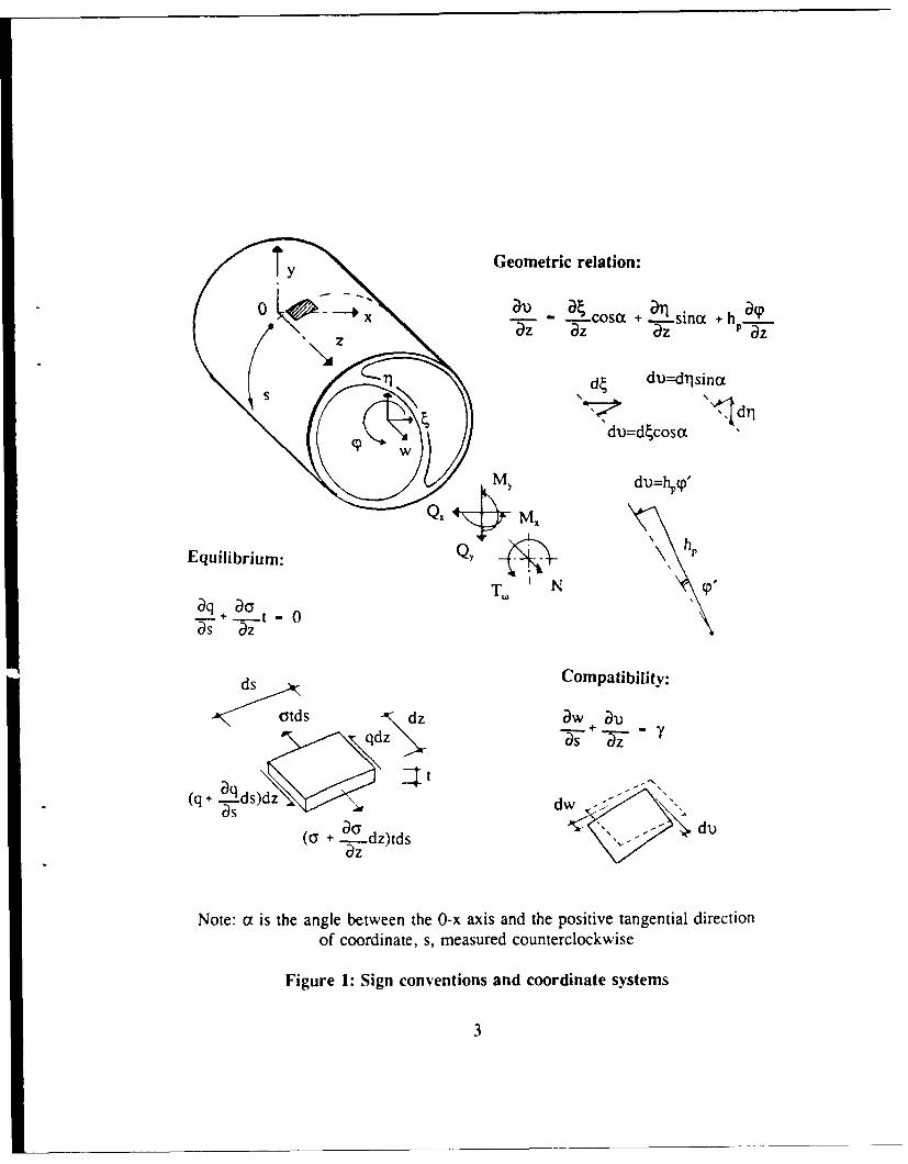
The sign conventions and coordinate systems of a thin-walled cross sectionsubjected to bending and torsion for the following theoretical development are illustratedin Fig. 1. Two coordinate systems are defined; a Cartesian coordinate system which hasx, y and z axes through the centre of gravity of the cross section and a curvilinearcoordinate system, s, which coincides with centreline of the wall of the cross section andis bounded with boundaries s=O and s=b. The Cartesian coordinate system hasdisplacements 4, i" and w along the x, y and z axes and a rotation (p around the z axis.The curvilinear coordinate system, on the other hand, has a displacement 1) along the saxis. The positive directions of forces and displacements are indicated by arrow heads.One should keep in mind that the sign conventions used here are different fromTimoshenko's definitions [9].
2.1 General Considerations
A small wall element cut from the thin wall beam as shown in Fig. I has an angleox between the s and x axes. The displacements between two coordinate systems can berelated to each other through geometric orientation as:
2
Ty Geometric relation:
0 x -Cosa + -21sinct + h -9
z- aZ az P az
71 d du:=dflsjna
dldim=dtcosa
MY diu=h,(p'
Equilibrium: QYy44
aq + -t -0
ds Compatibility:
-,- otd s dz aw Duqdz Y5 Ts
(q + Lqds)idz dw -as a ' -
(ay + 5z dz)tds
Note: (x is the angle between the 0-x axis and the positive tangential directionof coordinate, s, measured counterclockwise
Figure 1: Sign conventions and coordinate systems
3

al) . .----. cosa + arj sint + ___ (1)az az az P az
in which hp is the distance between the tangent of a wall element to the centre of rotation'p' of the cross section (it can be proved that the centre of rotation is also the shear centreof the cross section). The non-dependencies of a and hp from the z axis in this equationindicate that the beam is prismatic.
The equilibrium equations between internal resultants and external forces of across section are:
a dA N (a); fqh ds - Tp (d)
.f. xdA, M (b); fqcos ds = Q, (e) (2)
fa ydA, M~ (C); fqsinci ds - Q~ Mf
where A, is the cross section area. For a small wall element as shown in Fig. 1, theequilibrium equation in the longitudinal direction of the beam is
q + t 0(3)as az
where q and t are shear flow and wall thickness respectively.
The compatibility relation between displacement i) along the s axis and w alongthe z axis can be obtained through shear strain y as:
_w al) (4)+ __z
The constitutive relation of the material follows Hooke's law (linear elasticmaterial) as
t (5)G
where t and G are sLar stress and shear modulus respectively.
2.2 Pure Bending
It is convenient to describe the geometry of a cross section in an arbitrary
4
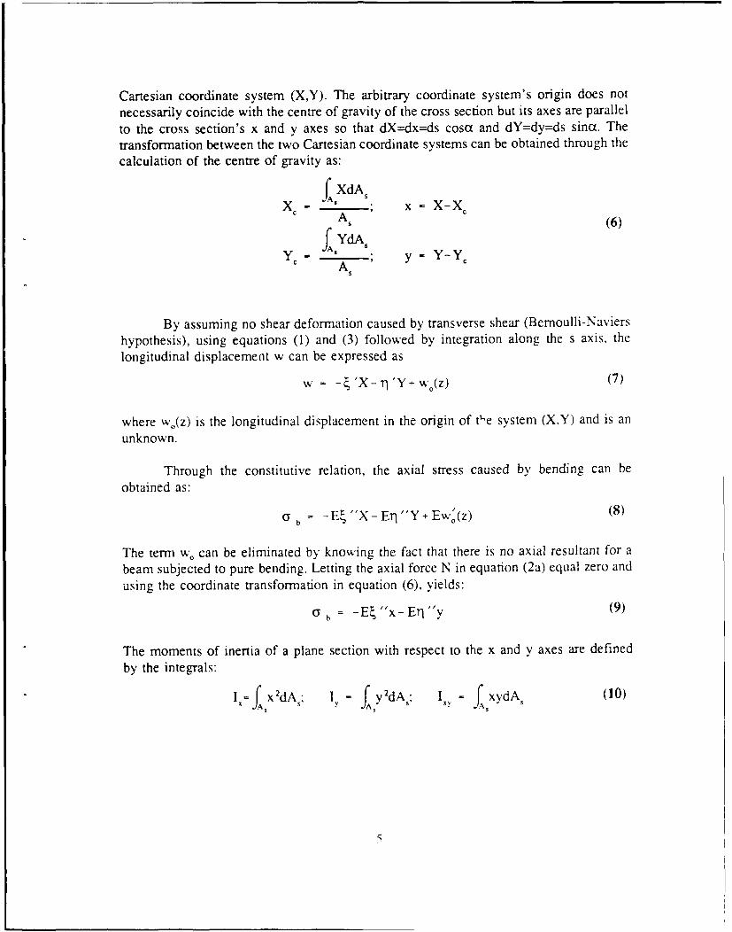
Cartesian coordinate system (X,Y). The arbitrary coordinate system's origin does not
necessarily coincide with the centre of gravity of the cross section but its axes are parallel
to the cross section's x and y axes so that dX=dx=ds cosx and dY=dy=ds sinot. The
transformation between the two Cartesian coordinate systems can be obtained through the
calculation of the centre of gravity as:
ISXdAX ; x - X-X cx A, (6)
Y IS , ; y- Y-YC
S A
By assuming no shear deformation caused by transverse shear (Bernoulli-Naviers
hypothesis), using equations (1) and (3) followed by integration along the s axis, the
longitudinal displacement w can be expressed as
w = - 'X- r1 'Y+ w(z) (7)
where w0(z) is the longitudinal displacement in the origin of tI'e system (X,Y) and is an
unknown.
Through the constitutive relation, the axial stress caused by bending can be
obtained as:E'b -E X- ETI"/Y Ew'(z) (8)
The term w, can be eliminated by knowing the fact that there is no axial resultant for a
beam subjected to pure bending. Letting the axial force N in equation (2a) equal zero and
using the coordinate transformation in equation (6), yields:
= -E "x-ETI"y (9)
The moments of inertia of a plane section with respect to the x and y axes are defined
by the integrals:
_fX2dA I, = f y2dA,, I - f xydAs (10)

The moment curvature relationships of a prismatic beam are expressed as:
- E XdA- Eil " xydA,- M,S (11)
-E'" xydA, -ETJ Y2dA - MS Y
By substituting these quantities into equation (9), the axial stress can be rewritten as:
Crb-Iyx -IXyM+ Ixy - IY YX(2S- +y~~~Y M1 IX (12)b D X D
where D = Iy - I Y2
The integration of equation (2) along the curvilinear coordinate leads to$
q(s,z) = q*(z) - JD° tds (13)0
where the constant qb represents the shear flow at the beginning of the integration. Theshear flow, qb vanishes for an open section with the integration starting at a free edge(shear flow equals zero at this point) and is unknown for a closed section in which theshear flow of the starting integration point usually is non-zero.
Introducing two integrals which represent static moments of a portion of the crosssection as:
S s
SX = fxtds; SY ytds (14)0 0
and substituting equation (12) into equation (13), one can obtainISIS IxSy-IS
________ _______ (15)qb = q-I'Y Y - Q ' y (1Q
D D
By defining two quantities
_IS IS ou _ xy (16)D qby D
6

and with the fact that qb is a linear combination of the shear forces Q, and Q,, equation(15) can be written as:
I S-lyS IS -I'SD Q) + (q;y- Y QY) (17)q,-(qbA D qD) OU •U O
- (qU+q')Q.q(qb + qb)Q
where superscript "u" can be interpreted as shear flow caused by a unit of shear force.
Since there is no twisting, the unit angle of twist is zero which indicates that
b =0(18)
0 t
Two unknown quantities q,," and qtu can be obtained as
ou b ou
f qb. ds f qbyds
qbX = - -- ; qb = - (19)fbd
b d
ti
They are equal to zero for an open section. On the other hand, for a multi-cell sectionwith n compartments these equations have to be satisfied for each cell and thus result inn simultaneous linear equations.
The moments of inertia in equations (12) and (15). based on the assumption of athin walled section, can be simplified by using integration by parts as:
b b
I f x2dA x2tds= xS lb _fSdx (20)o 0
Because the first term on the right hand side of the equation vanishes (according toequation (6), x is normalized so SJ0) and Sx(b) equal zero), the moments of inertia canbe expressed as
b b b b
I"--Sxdx; Iy- -fSydy ; %y - -fSxdy - -fSdx (21)
0 0 0 0
7

2.3 Twisting
There are no lateral displacements, and 1, for a beam subjected only to puretwisting around its centre of rotation. Thus, equation (3) can be reduced to
- "(hP (22)
According to the basic assumption that the shear deformation of the cross section is onlycaused by the St-Venant shear stresses, with equation (4), yields
a w h ( / + q ,
Gt (23)J P
2At
where A is the area of a closed section surrounded by the thin walls. The second term inthis equation vanishes for an open section.
By defining d2, = hrds and dQ 2 = J/(2At)ds, integrating equation (23) along thes axis, gives
w = -P /0 1+P/2 + wO(z) (24)
The warping normal stresses can be obtained by using Hooke's law derived as
o = -E 12 + E " 2+ Ew/(z) (25)
Letting w'/p"=i2o, and following Kollbrunner's [7] definition with a normalized sectorialcoordinate, will lead to
CO - Q I- Q2-2 .(26)
allowing the axial stress in equation (25) to be simplified as
C - -E p "CO (27)
The quantity Q. in equation (26) can be evaluated using the fact that the resultant axialforce acting on the cross section is equal to zero. Letting N in equation (2a) equal to zeroand integrating warping normal stresses along the s axis yields
8
b
f(f I- 92 2)tdsb (28)
f tds0
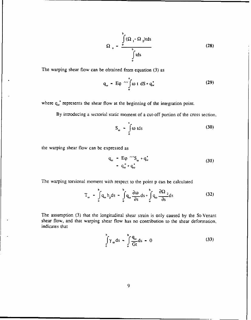
The warping shear flow can be obtained from equation (3) as
6
q, - E "'fco t dS.+ q (29)0
where q." represents the shear flow at the beginning of the integration point.
By introducing a sectorial static moment of a cut-off portion of the cross section,$
SW - fo tds (30)0
the warping shear flow can be expressed as
(= Etp .'S. + q- (31)=qW + q(D
The warping torsional moment with respect to the point p can be calculated
T.= fq. h ds = fq .ds+ fq. ds(32)0 P 0 s 0 a
The assumption (3) that the longitudinal shear strain is only caused by the St-Venantshear flow, and that warping shear flow has no contribution to the shear deformation,indicates that
b b
fy'ds - fqtds- 0 (33)0
9
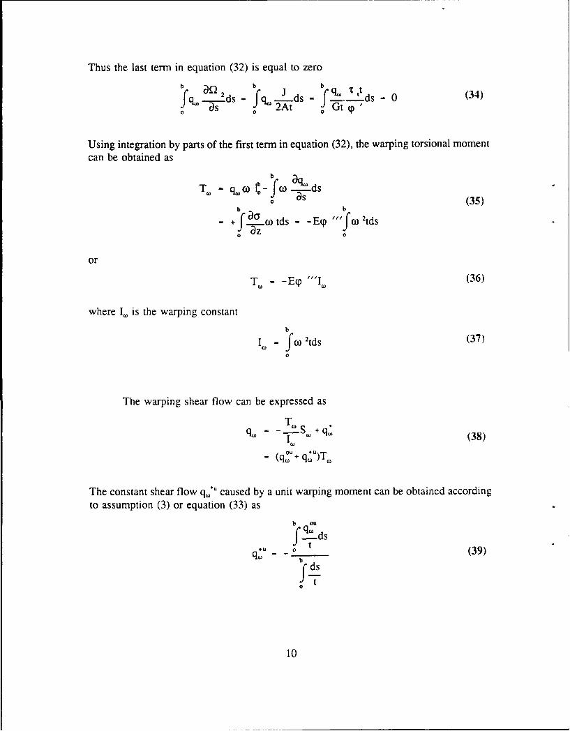
Thus the last term in equation (32) is equal to zero
b b b qttJ q .ds -Jfq. ds - f -. 2.ds - (340 0 2At a Gt (p
Using integration by parts of the first term in equation (32), the warping torsional momentcan be obtained as
b q
0 s (35)
-+ f auw tds - -Ep "fw 2tds0 Dz 0
orTo- -ECp "", (36)
where I., is the warping constantb
I- fc0 2 tds (37)0
The warping shear flow can be expressed as
Tq. = _iS +qI a) (38)
q- OU +q'u)T,(q() to-(
The constant shear flow q(,*U caused by a unit warping moment can be obtained accordingto assumption (3) or equation (33) as
b ou
f2 t o (39)
b
10

Defining M,'=T=. the warping normal stress can be expressed as
)(40)
The derivation of the above equations requires that the centre of rotation is knownin advance and that all the nodal coordinates refer to this point. Using geometricrelationships leads to
hPds - h ds-x sinat ds+ypcosa ds (41)
Letting dfl, = h, ds and using the fact that dy=sina ds and dx=cosz ds, the normalizedsectorial coordinate, 0t. can be expressed as
Co = Q C-xPy+ yx- 2 - o (42)
The centre of rotation can be evaluated by using the fact that there are no flexuralmoments under pure twisting. Letting equations (2b) and (2c) equal zero gives
b b
fa xtds - 0; fytds 0o o (43)b b
or fcoxtds -0; fw ytds 0o 0
Introducing equation (42) into (43), givesb b b b
fco txtds - xfyxtds+ yfx2tds -fo 2xtds = 0o o o o (44)b b b b
fo ytds - x y 2tds + yjpxytds - fn 2ytds = 00 0 0 0
Defining
b b
IX = J 2 xtds; IXQ= fn 2xtdso o (45)b b
IyoC= f Q cYtds; IY,- fQ 2ytds
0 0
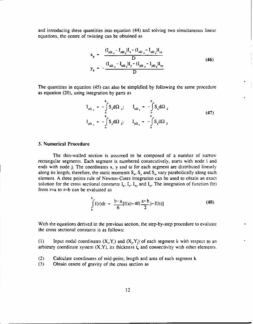
and introducing these quantities into equation (44) and solving two simultaneous linearequations, the centre of twisting can be obtained as
(y a - I )I, - (I' 0 - I )lxy
P - D (46)I m -- In DI (yn C- IyQ )I-y
YP'- D
The quantities in equation (45) can also be simplified by following the same procedureas equation (20), using integration by parts as
b b
I. c f SdQ 1., - - f SdQo o (47)b b
Iy - -fSd 2; I - -fSydQ 2o 0
3. Numerical Procedure
The thin-walled section is assumed to be composed of a number of narrowrectangular segments. Each segment is numbered consecutively, starts with node i andends with node j. The coordinates x, y and C for each segment are distributed linearlyalong its length; therefore, the static moments S1, Sy and S. vary parabolically along eachelement. A three points rule of Newton-Cotes integration can be used to obtain an exactsolution for the cross sectional constants I., Iy, Iiy and I.. The integration of function f(r)from r=a to r=b can be evaluated as
bff(r)dr - b6a [f(a)+4f(.)+ f(b)] (48)
With the equations derived in the previous section, the step-by-step procedure to evaluatethe cross sectional constants is as follows:
(1) Input nodal coordinates (X2,Yj) and (X,,Y,) of each segment k with respect to anarbitrary coordinate system (X,Y), its thickness tk and connectivity with other elements.
(2) Calculate coordinates of mid-point, length and area of each segment k(3) Obtain centre of gravity of the cross section as
12

X*XX k - ,I + AXk - Xi- X J
Y .+.Y~Xk 2 Y ,+ AYk = Yi- Yj
2
Lk = AX 2 +AY 2 ; Ak - Lktk
X k A k. YkAk
and the nodal and mid-point coordinate of each segment (x,,y,), (xj,yj) and (Xk,Yk) withrespect to the new origin (Xe, Y,) as
x - X-Xc; y = Y-Y,
(4) Calculate the static moments S,, and Sy of a cut of portion of the cross section forpoints i, j and k of each segment as
ASX Ak(X + Xk); S., = S,,+ASS 4
AS, A k(y, + Yk) . S - S ASy4 y
(5) Obtain the moments of inertia of the cross section ask AXk k AYk
I, - k- [. [S (i)+4S(k)+S (j)]; I, . - S (i)+4S (k) S )n-I 6 6k AY k AX
P -- [SX(i)+4Sx(k)+S,(j)]; IY,, - Z __.[Sy(i)+4SY(k)+S()1n-I 6 n-I 6
k6) Calculate Af 2ck as
Ac k - xkAYk- ykAXk
(7) Evaluate Af.2k as
LkA 2k - 2K-'A-
tk
13
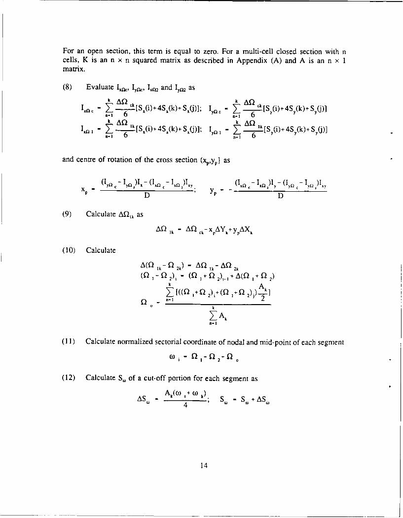
For an open section, this term is equal to zero. For a multi-cell closed section with ncells, K is an n x n squared matrix as described in Appendix (A) and A is an n x 1matrix.
(8) Evaluate I2, Iyk, I,tQ, and Iy. ask AD ) k AQkc - -Af k [S(i) 4So(k) S,()]; c - k.. ck[s (i).4S,(k)S
n-i 6 n-I 6
Ir, - 1. A .[S (i)+4S.(k)+S (j)]; Iy - >3 I [S (i)+4S (k)+Sn-i 6 n-I 6
and centre of rotation of the cross section (xp,yp) as
(I y-I )l -(I n - In)Ixy. (Ita - 1"0x )Iy -(Iy0 1c-
P D P D
(9) Calculate AK2,, as
A Ik = AQ ck- xPAYk+ ypAXk
(10) Calculate
(Q -Q Q 2k
(1 2) (Q 1 + 2).1 A(Q I + 2)k
± o I(Q 2)i+(Q I+ Q 2))k0 k
Z Akn-I
(11) Calculate normalized sectorial coordinate of nodal and mid-point of each segment
c0i - I - Q 2- f
(12) Calculate S. of a cut-off portion for each segment as
AS. Ak(O) 1+ 0) k) S - S,+AS
14
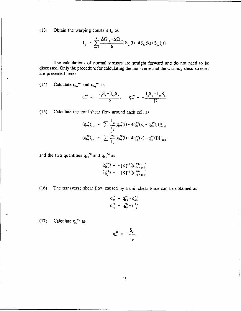
(13) Obtain the warping constant I, as
I~) - '6 2 [SW(i)+4S (k)+S.(j)]
The calculations of normal stresses are straight forward and do not need to bediscussed. Only the procedure for calculating the transverse and the warping shear stressesare presented here:
(14) Calculate q,, * and qby' as
1 - -S oY Y Cu lKy- xy S.qbD"- D ' D
(15) Calculate the total shear flow around each cell as
(qb)cl - [Z- [qb (i)+ 4qou(k)+ qu(J)]]c,,
tk
(qu)c,, " .2 k[qo,(i)+ 4qoy(k)+ qo.() ],,
and the two quantities qb, and qb> as(q•ul - -[K] - '((qO)cll
(qbx} = - bfq~u - 1 o-'qu)
(16) The transverse shear flow caused by a unit shear force can be obtained asU CU *utq "qou qbu
bx bx ±U OU *
qby - qby + qby
(17) Calculate qOU as
Cu cqw I1A)
15

(18) Calculate the total shear flow around each cell as
(qOu) _ [- Z k[q.Ou(i) +4qOu(k) + q cOll,,tk
and q()u as{q* ) - -[K] - '((qu ).i,
(19) The warping shear flow caused by a unit shear force can be obtained asU OU *uqW - q( + qQ
(19) The shear flows caused by different forces now can be evaluated by multiplyingthese unit shear flows with applied forces.
The above procedure can be applied on not only the closed sections but also the opensections by letting the quantities Q2 and q" equal zero.
16

4. Examples
Two examples are presented in this section in tabular form in order to demonstratethe above procedure. The Arabic numeral in the first row of each table indicates the stepnumber. The results can be verified with the equilibrium condition.
Example 1: A single-cell box beam with different wall thicknesses is shown in figure2. (a) Calculate the cross sectional constants and shear centre. (b) Calculate the transverseshear flow caused by transverse shear forces Q,=-5.5 x 10⁵ kN and Qy=-4.125 x I0 kN.(c) Calculate the warping shear flow due to a unit warping moment.
[K] = 135 {A) {15x10 4)
Xv = 88.6 Y= 298.6- yp'~X x=-10.32 y=-13.83
XP 78.28 YP =312.43t I20 (2 I1 = 56.84 x 10⁷
2 IY 47.49 x l0 J 6.67 x 10⁸
4 1.2,Iy 15.91 X 10⁷
300 Iv = 11.71 x 101°41 (qou} = (-15372 X 105}
{qby) = {10369 x 1051 -- 400 -X {qwo-) = (-96.37 x 10⁵ }
Transverse shear flow Warping shear flow
(Normalized)
Figure 2: Single-cell box beam
17

(I) (2) (3)I (4) (5) (6)1 (7)1 (8)1
elem t node X X L XkA x ASx S, 1+4+1 I, Ixy ADU A2a I. Ixfu
I 0 10' 1 -8 10' [ 0 10 10' 10' 1010 1010
-88.6 0
0.29
1 10 200 400 500 5 10 111.4 0.29 6.74 26.96 20.22 92860 111111 6.26 7.49
5.29
2 400 311,4 5.58
4.0
2 10 310 -180 300 3 9.3 221.4 9.58 56.13 -101.03 134.71 74988 66666 42.09 37.42
2.65
3 220 131.4 12.23
1.57
3 10 20 -400 500 10 2 -68.6 13.8 72.8 -291.2 -218.4 57140 55556 41.6 40.44
-8.43
4 -180 -268.6 5.37
-3.35
4 20 -90 180 300 3 -2.7 -178.6 2.02 13.46 24.21 -32.28 75012 66667 10,09 8.97
-2.0
1 0 -88.6 0
21 18.6 -341.06 -95.75 100.04 94.32
88.6 -E./6 56.84 15.91 -16.67 -15.72
18
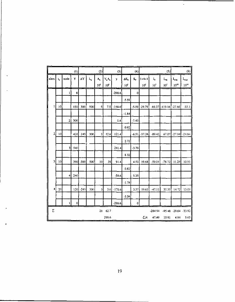
(1)1 (2)! (3)[ (4)( (5) (8)lem L n Y AY I.. Ak Y Ak. y AS , S y 1+4+1 I f I " IYck Ivm
ios I W loo I W 10' 10' lo 1010
1 0-298.6 0
-5.59
1 10 150 300 500 5 7.5 -148.6 -5.59 -29.79 -89.37 -119.16 -27.66 -33.1
-1.84
2 300 1.4 -7.43
0.92
2 10 420 240 300 3 12.6 121.4 -6.51 -37.26 -89.42 67.07 -27.94 -24-84
2.72
3 540 241.4 -3.79
8.32
3 10 390 -300 500 10 39 91.4 4.53 19.68 -59.04 -78.72 11.24 10.93
0.82
4 240 -58.6 5.35
-1.78
4 20 120 -240 300 3 3.6 -178.6 3.57 19.63 -47.11 35.33 14-72 13.09
-3.56
1 0 1-28.6 0
21 62.7 -284.94 -95.48 -29.64 -33.92
298.6 -E/6 47.49 15.91 4.94 5.65
19
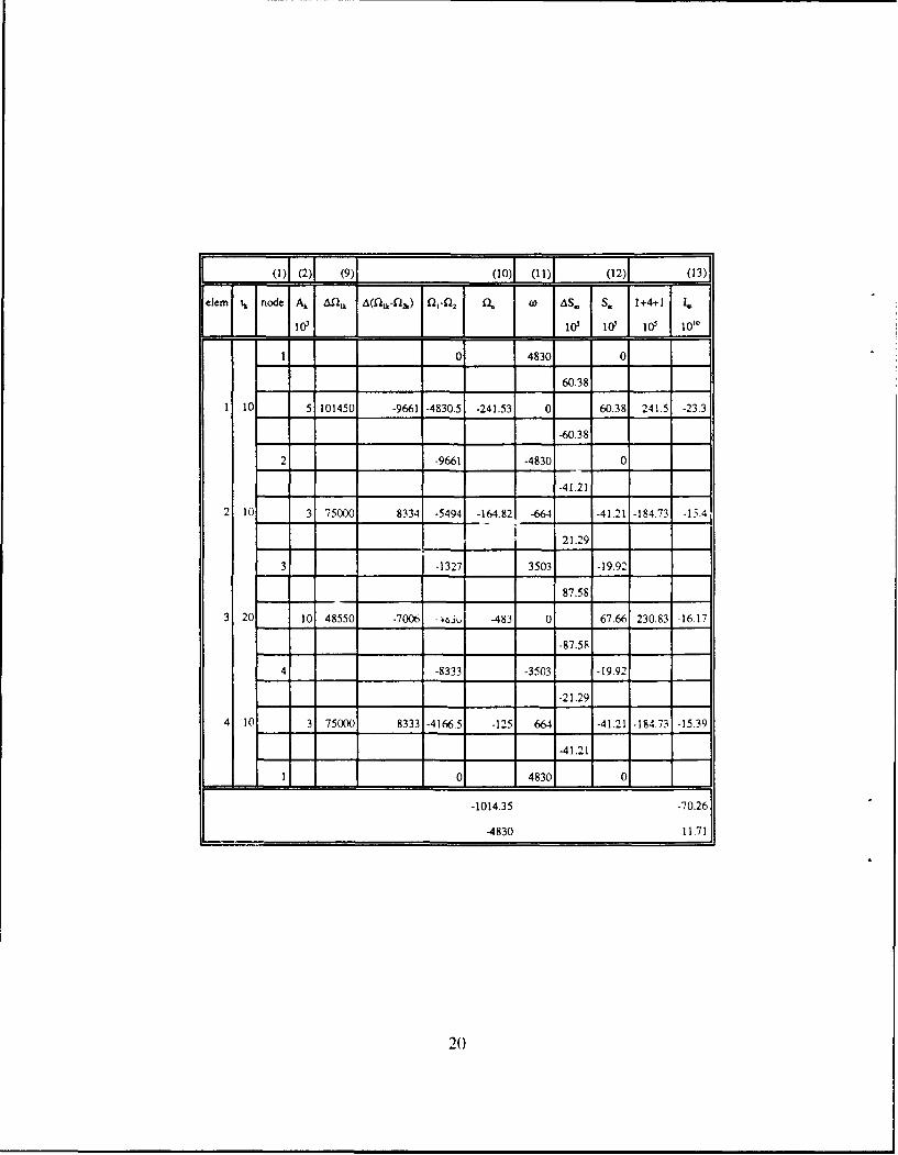
(1)1 (2)1 (9)1 (10) (11) (12) (13)1
elem t . node A L Mllk A(1l l ) f ll- Ql . AS . s 1+4+11 /
los l~~W lo o 1 t
1 0 4830 0
60.38
1 10 5 101450 -9661 -4830.5 -241.53 0 60.38 241.5 -23.3
-60.38
2 -9661 -4830 0
-41.21
2 10 3 75000 8334 -5494 -164.82 -664 -41.21 -184.73 -15.4
21.29
3 -1327 3503 -19.92
87.58
3 20 10 48550 -7006 - -483 0 67.66 230.83 -16 17
-87.58
4 -8333 -3503 -19.92
-21.29
4 10 3 75000 8333 -4166.5 -125 664 -41.21 -184.73 -15.39
-41.21
1 0 4830 0
-1014.35 -70.26
-4830 11.71
20

(1)l (2)l (14)1 (15)l (16)j (14)1 (15)1 (16) (17)L (18)1 (19) (20)1
clem L, I kI qb,- 1+4+1 qt.' q,;" 1+4+1 q," q,," 1+4+1 q."
Ias 10, 10s lOs 11 10"s 1-1 1Ior I kN/mmI
0 113.9 0 -76.8 0 0.71 -308
1 500 50 -41.9 -323.9 72 128.1 720.4 51.3 -5.16 -20.64 -4.45 -607
-156.3 -42.4 208 131.2 0 0.71 -308
2 300 30 -228.3 -1331.1 -114.4 213 1227.5 136.2 3.52 15.78 4.23 67
-261.6 -147.7 167.5 90.7 1.7 2.41 438
3 500 25 -238.6 -1285.2 -124.7 -15.3 17.2 -92.1 -5.78 -19.72 -5.07 1066
-69.2 44.7 -89.1 -165.9 1.7 2.41 438
4 300 30 -15.8 -132.4 98.1 -69.9 -368.7 -146.7 3.52 15.78 4.23 66
01 113.9 0 -76.8 0 0.71 -308
135
113.9 -76.8 0.71
21

Example 2: For a two-cell section with constant wall thicknesses as shown figure 3,calculate (a) the cross sectional constants and shear centre, (b) the transverse shear flowcaused by Q and QY equal to 105 kN, and (c) the warping shear flow caused by a unitwarping moment.
40 40[-1216.56 -56.56] A 4l1400_______ 40056.56 216.5611 24x1043
5 4 1, =287.66 x 10"1,, = 287.66 x 10⁷
03400 I,Y, -53 .69 x 101cell 2 3 © 2 1.) 2453.36 x 1010
CS =1 1 00J =2.88 x W0
cell 1I-98xo
(q Ou) - fqo';)- 297i5
6 X x b 5887xIO-11=, 327.5 Y, 327.5 J -52l7.33xl10 5
=P -65.04 =p -65.04 {q Oul=P 262.46 YP =262.46 -52 17.33xl10-5j
(Normalized)
Transverse shearnfow Warping shear flow
Figure 3: Mlulti-cell section
22

( ) (2) (3) (4) (5) (6) (7)I (S)
em~ . node X 1 X L. A. Y.A AS, S. 1+01 Ix I I *
= I lo- loI I& 10 W loll
1 8o 472.5 0
9.45
1 10 800 0 400 4 32 472.5 9.45 56.7 0 226.8 189016 120000 107.2 68
9.45
2 800 472.5 13.9
7.45
2 10 6M0 -400 400 4 24 272.5 26.35 154.1 -616.4 0 29016 120000 44.7 184.93
3.45
3 400 72.5 29-8
1.45
3 10 400 0 400 4 16 72.5 31.25 187.5 0 750 29016 12000 54.4 22503
1.45
4 400 72.5 32.7
-0.55
4 10 200 -. 1O40D 4 8 -172.5 32.15 188.9 -755.6 0 189016 120000 357.1 226.7
-4.55
5 0 -327.5 27.6
-13,1
5 10 0 0 80 8 0. 327,5 14.5 87 0 -696 261968 24000 228 208+92
-131
6 0 -327.5 1.4
-5.81'
-5.
6 10 4001 800 800 8 32 72.5 -10.9 -4941 -395.28 0 262012 240070 -129.4 -118.54
10.9
1 800 472.5 0
3 400 72.5 0
-0.78
200 -400 565 5.71 11.4 .127.5 -0,78 -10.33 41.32 41.32 0 0 0 0
-643
S 0-327 -711
123.4 -1725.96 322.12 662 79494
327.5 -E/6 287.66 -5369 -1103 -132.5
23

(I) -* * (2)1 = ( ) (4)j =5)J = (9)1
node Y AY Y% A, YA Y AS, S, 1+4+1 1, ll, IY VQ
1 10 'I ji 0'i 10 j 0 10' 10' 10 10
1 0 -327.5 0
1 10 20D 400 400 4 8 -127.5 .4.55 -23.3 -932 0 -44 -27.96
-0.55
2 40 72.5 -5.1
1.45
2 10 40 0 40 4 16 72.5 -3.65 -21.9 0 87,58 -6.4 -26.27
1.45
3 40D 72,5 -2.2
3.45
3 10 60 40D 4WU 4 24 272.5 1.25 11.5 46 0 3.3 13.82
7.45
4 80D 472.5 8.7
9.45
4 10 800 0 40D 4 32 472.5 18.15 108.9 0 -435.7 205.8 13071
9,45
5 00 1 472.5 27.6
10.9
5 10 40 -8001 800 8 32 72.5 385 215 -1720 0 563.3 516.01
-5.1
6 0 -327.5 334
262'
-13.1
6 10 0 0 800 8 0-327.5 13.1 78.6 0 628.62 205.9 188-56
-13.1
1 0 -327.5 0
3 40D 72.5 0
-0.78
7 10 200 -400 565 5.7 11.4 -127.5 -0.78 -10.33 41.32 41.32 0 0
-643
6 0 -327.5 -7.21= - - = - = - =C= = -
37.7 123.4 -1725.% 321.72 928 794.94
327.5 -E/6 287.66 -53.69 -1546 -132.5
24

(1)1 (2)1 (9)j (10)1 (11)1 (12)1 13
lo, IO& Wo lo 0 oll
0 .30064 0
-126.1
1 10 4 215032 95032 47516 1900.64 17452 -126.1 193.6 183.9
324.2
2 95032 64968 698.1
974.5
2 10 4 55032 -64968 62548 2501.92 32434 1672.6 9385.9 -6097.8
324.1
3 30D64 0 1997.4
-324.8
3 10 4 55032 -64968 -2420 -96.3 .32494 1672.6 93859 -6097.8
-974.5
4 -34904 -64968 698 1
-824.2
4 10 4 215032 95032 12612 504.48 -17452 -126.1 193.6 1839
126.1
5 60128 30064 0
901.9
5 10 8 21 O000 -30064 45096 3607.t 15032 901.9 48102 -1446.2
300.6
6 30064 0 1202.5
-300.6
6 10 8 210000 -30064 15032 1202.56 -15032 901.9 48102 .1446.2
-901.9
30O64 -30064 0
31 30064 0 0
0
7 10 5.7 0 0 30064 1713.65 0 0 0 0
0
6 300,64 01]
11334.1 -147202
30064 2453.36
25

-O1 10' lo' 10 10' 10 10 10" 10 KN/m
0 3537 0 35.37 0 326 70.74
1 400 40 .3098 -188.57 439 0,03 4578 45.4 5.14 -7.29 37.74 49.79
-6463 -2.2 5.66 41.03 -284s 4.15 11.75
2 40o 40 -9245 -5,0.3 57.08 -4.57 -24.73 30.8 -68.12 .382.59 -35.58 .26.28
-105.A5 -704 .12.11 23.26 -81.42 -48.82 -47.22
.10535 -23.25 .12.11 70.49 -81.42 -48.82 47.22
3 400 40 -113.4 -683.09 -308 -25.51 -167.46 57.09 -68.18 .382.59 -35.58 26-29
-123.63 -41.03 -5331 29.29 .2845 4.15 -11.74
4 400) 40 -128 -753.59 -454 .i6.98 -519.19 -4.38 5.14 -7.89 37.74 -49.78
-117.96 -35.36 -117.96 -3536 0 32.6 -70.72
5 So 80 .71 11 -457.9 4.49 .14242 -832.88 -65.82 -36.76 -196.06 -4.16 -61.33
.27.5 55.1 .121.24 -3864 -49.02 -16.42 -16.46
3.31 38.68 .9046 -55.09 -49.02 -16.42 -16.46
6 I00 so 30.45 125.11 65.82 -39-86 -249.9 -4.49 -36.76 -196.06 -4.16 61.33
0 35.37 0 35.36 0 326 70.73
0 -4723 0 -47.23 0 0 94.46
7 565 56.3 3.33 43.32 -439 333 43.32 -43.9 0 0 0 27.8
3.33 -17.23 30 .17.23 0 0 34.46
35.37 35-37 32,6
32.6 826 32.6
26
5. Concluding Remarks
This report has presented the complete mathematical derivations of the equationsused for the calculation of cross sectional constants and stress distributions of thin-walledsections. The derivations are based on the same assumptions as Kollbrunner's [7] opensection and extend to multi-cell closed sections. These equations can be used for anyshape of cross section, both open and closed, and are independent of the orientation ofthe cross section. A numerical procedure based on these equations has been outlined andverified with several examples. It can be easily implemented into the current SCRAPprogram.
It should be noted that these equations, which are based on certain assumptions,have some limitations. The major two are that the derivations deal only with prismaticmembers, and cross sections retain their shape during deformation. Thus, the solutions ofthe equivalent beam models can only be improved with increasing numbers of beamelements, and are only valid for the unbuckled state of the ship hull's elastic response.
27
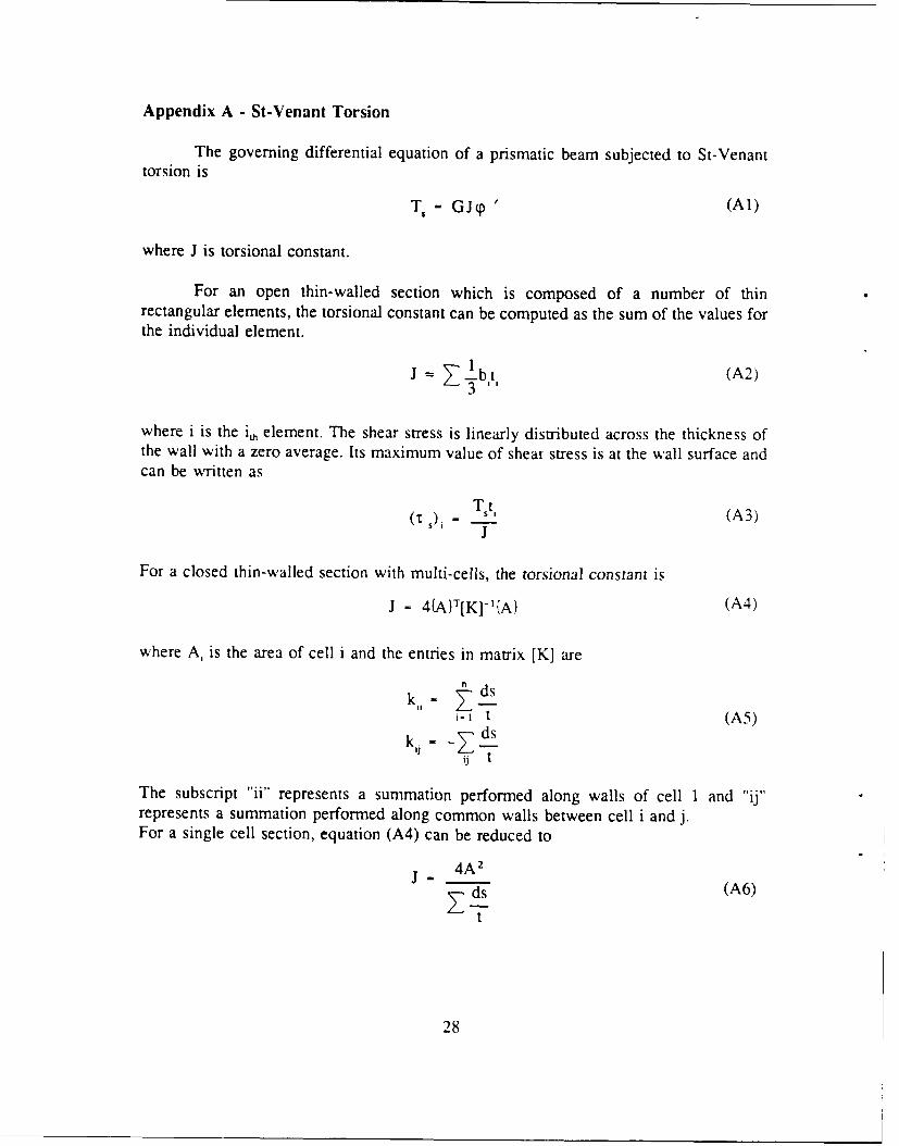
Appendix A - St-Venant Torsion
The governing differential equation of a prismatic beam subjected to St-Venanttorsion is
TS - GJp' (A1)
where J is torsional constant.
For an open thin-walled section which is composed of a number of thinrectangular elements, the torsional constant can be computed as the sum of the values forthe individual element.
J = Z 3bt (A2),3 1
where i is the ih element. The shear stress is linearly distributed across the thickness ofthe wall with a zero average. Its maximum value of shear stress is at the wall surface andcan be written as
(t ), st (A3)
J
For a closed thin-walled section with multi-cells, the torsional constant is
J = 4{A}T[K]-'(A) (A4)
where A, is the area of cell i and the entries in matrix [K] aren-ds
i-I t (A5)
k, - dsij t
The subscript "ii" represents a summation performed along walls of cell 1 and "ij"represents a summation performed along common walls between cell i and j.For a single cell section, equation (A4) can be reduced to
4A2 (A6)
t
28
For a beam subjected to a specified torsion T, the rate of twisting angle (P' can be
obtained from equation (Al). The St-Venant shear flow (q,), in each cell then can be
found as
{q) - 2Gp '[K]-{'(AT (A7)
29
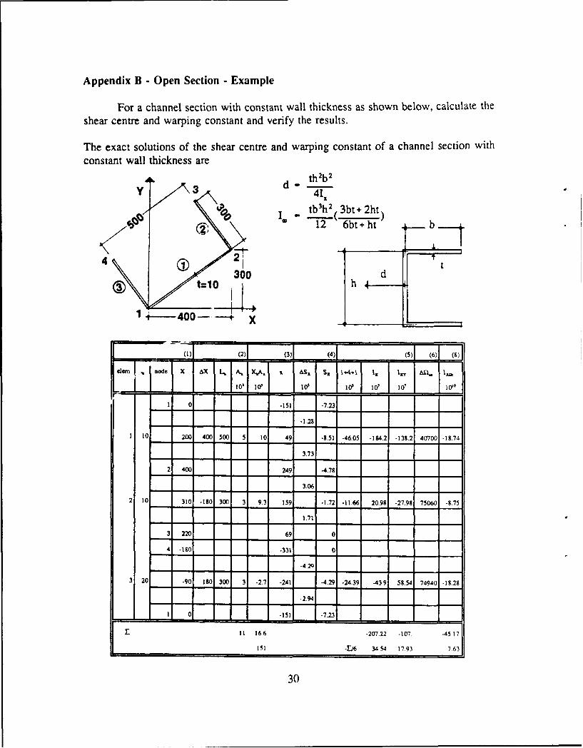
Appendix B - Open Section - Example
For a channel section with constant wall thickness as shown below, calculate theshear centre and warping constant and verify the results.
The exact solutions of the shear centre and warping constant of a channel section withconstant wall thickness are
Sd th'b 2
> 27 12 6bt + ht G_ 2b4 2
300 d
14-_400-- 4 X
(= (2)1 (3)J (4)1 (5) (6)1 (8]l, ,,n node€ X AX I. Au XA,. &Sr Sx 144+ l, 1 " All l ,,I 10'1 0' ' 10 10' 10 '11
1 0 -151 -7.23
-1.28
1 10 200 400 500 5 10 49 -2.51 -4605 -184.2 -138.2 40700 -1874
3.73
2 400 249 -4.78
3,06
2 10 310 -180 300 3 9.3 159 -1.72 -11.66 20.98 -27.98 75060 -8.75
1.71 I
3 220 69 0
4 -10 -331 o
-4.29
20 -90 180 300 3 -27 -241 -4.29 -24.39 -43.9 58.54 74940 -1828
294
1 0 -151 -723
II 166 -207.22 -I07. -4517
151 -E/6 3454 17.93 7631
30
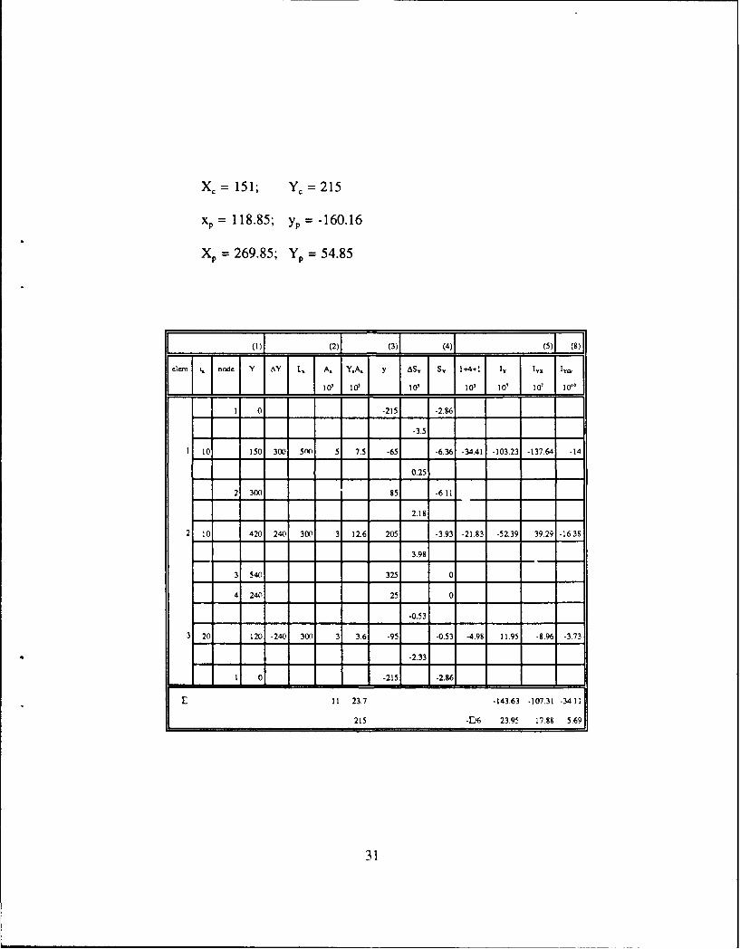
Xc= 151; Y, = 215
xp= 118.85; y, =-160.16
Xp= 269.85; Yp = 54.85
_(2) (3) (4) (5)(8)
elearn t. n de Y Y L., A . Y,, y AS y S y 1+4 +1 Iv I Y I-€a,
1 0 , j0[d 1 . ] 1 0 1 0 , l 0 ly ,
1 0 -215 -2.86
-3.5
10 150 300 5(X 5 7.5 -65 -6.36 -34.41 -103.23 -137.64 .14
0.25
2 300 85 -611
2.18
2 10 420 240 300) 31 116 205 -3.93 .21.83 -52,39, 39.29 -1638
3.98
3540 325 0
4 240 25 0
3 20 120 -240 300 3 36 -95 -0.53 -4.98 11.95 -8.96 -3.73
-2.33
0-215 -2.86
11 23.7 -143.63 -107.31 -34.11
215 -E/6 23.95 17,88 5.69
31
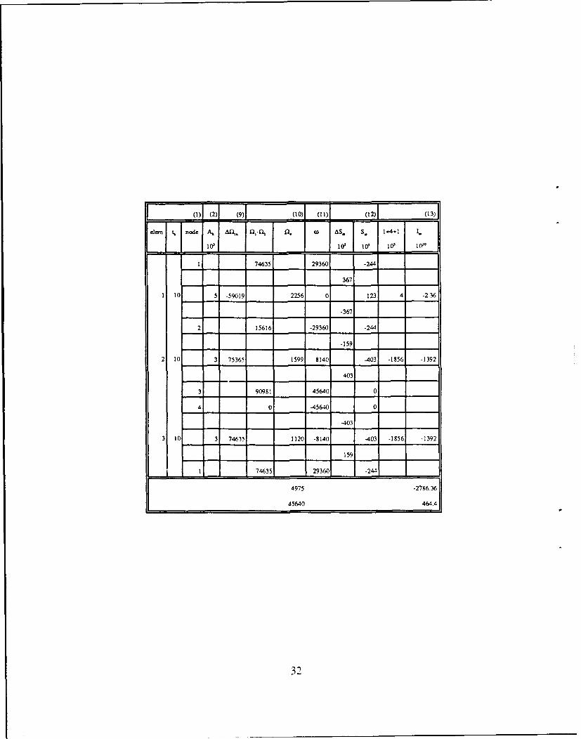
01 (2)1 (9)I (10) (11) (12) (13)
en I, node A, AR,~ 0,41f, 0. IAs.I S. 1++ 1.
- 100' 1 l 0' I I op I 101.
1 74635 29360 -244
367
1 10 5 .59019 2256 0 123 4 -236
-367
2 15616 -29360 -244
-159
2 10 3 75365 1599 8140 -403 -1856 -1392
403
3 90981 45640 0
4 0 -45640 0
-403
3 10 3 74635 1120 .8140 -403 -1856 -1392
159
- - 74635 29360 -24-
4975 .2786.36
45640 46441
32

References
1. "Vibration and Strength Analysis Program (VAST), Version #06, User's Manual",Martec Ltd., Halfax, N.S., 1990.
2. Pedersen, P.T., A Beam Model for the Torsional-Bending Response of ShipHulls, Transactions, RINA, 1983.
3. Vernon, T.A., "SCRAP, A Computer Program for Elastic Strength Analysis andEquivalent Beam Modelling of Ship Hulls", DREA Technical Memorandum86/214, 1986.
4. Vernon, T.A., "SCRAP - Operational notes", informal communication, 1985.
5. Vernon, T.A., Nadeau, Y., "Thin-Walled Beam Theories and Their Applicationsin the Torsional Strength Analysis of Ship Hulls", DREA Technical Memorandum87/202, 1987.
6. Kumar, R., "SCRAP - Ship Cross-Section Analysis Program, User's Manual",Martec Ltd., Halifax, N.S., DREA CR/90/438, 1990.
7. Kollbrunner, C. F., Basler, K., Torsion in Structures, Springer-Verlag, Berlin,1969.
8. Hughes, 0. F., Ship Structural Design, John Wiley & Sons, N.Y., 1983.
9. Gere. J. NI. and Timoshenko, S., Mechanics of Materials, Wadsworth. Inc..Belmont, California, 1984.
33
UNCLASSIFIEDSECURITY CLASSIFICATION OF FORM
(highest classification of Tele, Abstract. Keywords)
DOCUMENT CONTROL DATA(Security classification of title, body of abstract and indexing annotation must be entered when the overall document is classified)
1. ORIGINATOR (The name and address of the organization preparing the 2. SECURITY CLASSIFICATIONdocument. Organizations for whom the document was prepared, e.g. (Overall security of the document includingEstablishment sponsoring a contractors report, or tasking agency, are entered special warning terms if applicable.)In section 8.)
Defence Research Establishment Atlantic UnclassifiedP.O. Box 1012, Dartmouth, N.S. B2Y 3Z7
3. TITLE (The complete document title as indicated on the title page. Its classification should be Indicated by the appropriateabbreviation (SC.R or U) in parentheses after the title.)
Cross Sectional Constants and Stress Distributions of Thin-Walled Sections
4. AUTHORS (Last name, first name. middle initial. It military. show rank. e.g. Doe. Mal. John E.)
Hu, Thomas S.Z.
5. DATE OF PUBLICATION (Month and year of publication of 6a. NO OF PAGES (Total 6b. NO. OF REFS. (Totaldocument.) containing information, cited in document.)
Include Annexes, Appendices.
March 1992 etc.) 41 9
6. DESCRIPTIVE NOTES (The category of the document. e.g. technical report, technical note or memorandum. It appropriate, enterthe type of report, e.g. interim, progress, summary, annual or final. Give the inclusive dates when a specific reporting period iscovered.)
DREA Technical Memorandum
. SPONSORING ACTIVITY (The name of the department project office or laboratory sponsoring the reseach and development, includethe address.)
9a. PROJECT OR GRANT NUMBER (If appropriate, the 9b. CONTRACT NUMBER (If appropriate, the applicable numberapplicable research and development project or grant number under which the document was written.)under which the document was written. Please specify whetherproject or grant.)
Project 1AH10a. ORIGINATOR'S DOCUMENT NUMBER (The official documen 10b. OTHER DOCUMENT NUMBERS (Any other numbers which
number by which the document is identified by the originatnng may be assigned this document either by the originator or byactivity. This number mrst be unique to this document.) the sponsor.)
DREA Technical Memorandum 92/209
11. DOCUMENT AVAILABILITY (Any limitations on further dissemination o the document. other than those imposed by securityclassification)
X) Unlimited distributionDistribution limited to detence departments and detence contractors; further distribution only as approvedDistri-.ution limited to defence departments and Canadian defence contractors; further distribution only as approvedDistribution limited to government departments and agencies; luther distribution only as approvedDistribution limited to defence departments; further distribution only as approvedOther (please specify):
12. DOCUMENT ANNOUNCEMENT (Any limitation to the bibliographic annoucement of this document. This will normally correspond tothe Document Availability (11). However, where luther distribution (beyond the audience specified in 11) is possible, a widerannouncement audience may be selected
UNCLASSIFIEDSECURITY CLASSIFICATION OF FORM 0=_ 2,0687
35
UNCLASSIFIEDSECURITY CLASSIFICATION OF FORM
13. ABSTRACT (A brief and factual summary of the document. It may also appear elsewhere in the body of the document Itself. It ishighly desirable that the abstract of classified documents be unclassified. Each paragraph of the abstract shall begin with an Indicationof the security classification of the Information in the paragraph (unless the document itself Is unclassified) represented as (S). (C),(R). or (U). It is not necessary to include here abstracts In both offical languages unless the text is bilingual)
The equivalent beam model is widely used for predicting strength and vibrationof a ship hull in a preliminary analysis. It can also be used for checking results in a largefinite element model and for parametric studies of ship behaviour. This method treats aship hull as a series of prismatic segments connected together. Each segment has itssectional properties, real and virtual masses. The program SCRAP was developed atDefence Research Establishment Atlantic for calculation of cross sectional constants andestimation of mass properties. It prepares input data files for the finite element programsVAST and TORSON and interprets the analytical results. SCRAP can be only used forsome specific sections at the present time. For arbitrarily oriented sections it may give anincorrect shear centre and warping constant and thus the wrong stress distributions.
This report presents the mathematical derivations of the equations used for thecalculation of cross sectional constants and stress distributions of thin-walled sections. Asan improvement over the current SCRAP program, these equations are applicable to anyshape of cross section, both open and closed, and are independent of the orientation ofthe cross section. A computer-oriented step-by-step procedure based on these equationsis outlined. Several examples are also presented to verify the procedure.
14. KEYWORDS. DESCRIPTORS or IDENTIFIERS (Technically meaningful terms or short phrases that characterize a document and couldbe helpful in cataloguing the document. They should be selected so that no security classification is required. Identifirs, such asequipment model designation, trade name. military project code name. geographic location may also be included. If possible keywordsshould be selected from a published thesaurus. e.g. Thesaurus of Engineering and Scientific Terms (TEST) and that thesaurus-identified. If it is not possible to setect indexing terms which are Unclassified, the classification of each should be indicated as with thetitle,)
Thin-walledWarpingSectional constantsStress
UNCLASSIFIEDSECURITY CLASSIFICATION OF FORM
36