Embed Size (px)
Citation preview

rrr '.*
MIL-STD-7566 NOTICE 1 31 August 1982
MILITARY STANDARD
RELIABILITY MODELING AND PREDICTION
TO ALL HOLDERS OF MIL-STD-7566:
1. THE FOLLOWlNG PAGES OF MIL-STD-756B HAVE BEEN REVISED AND SUPERSEDE THE PAGES LISTED:
New Page - Date Superseded Page Date
V 31 August 1982 V v i 31 August 1982 v i
18 November 1981 18 November 1981
2 . MAKE THE FOLLOkING PEN AND I N K CHANGES:
(a )
( b )
( c ) Page 1001-7 add 'I=" between PA , P6 =P6 , and P c =Pc.
Page 1001-4 add " ( 1 1 ) " t o t h e r i g h t o f P s = PAPBP1P2.
Page 1001-6 add " ( 1 5 ) " t o t h e r i g h t o f P s = PAPB PC . 2 2
2 2
( d ) Page 1002-3 add " ( 2 ) " t o t h e r i g h t o f PS = 61E$1C2A+... .......+B162CiC2A.
( e ) Page 1002-3 add " ( 3 ) " t o t h e r i g h t o f PS = 61C1+ ........ +61E'2C1 C2A.
( f ) Page 1003-4 add " ( 1 ) " t o t h e r i g h t o f Ps = A[C1+C1c2]+ .... . . . .+61C,B2C2].
3. RETA IN T H I S NOTICE AND INSERT BEFORE TABLE OF CONTENTS.
4. i n d i c a t e d above have been entered. check sheet. Th is issuance, t oge the r w i t h appended pages, i s a separate p u b l i c a t i o n . Each n o t i c e i s t o be r e t a i n e d by s tock ing p o i n t s u n t i l t h e m i l i t a r y s tandard i s complete ly r e v i s e d o r canceled.
Holders of MIL-STD-7566 w i l l v e r i f y t h a t page changes and a d d i t i o n s Th i s n o t i c e page w i l l be r e t a i n e d as a
Custodi ans : Army - CR Navy - AS A i r Force - 17
Review A c t i v i t i e s : Army - EA, AR Navy - SH, US
Users : A r m y - AM Navy - EC Nat iona l S e c u r i t y Agency - NS Defense Mapping Agency - DMA
Prepar i ng A c t i v i t y : NAVY - AS
( P r o j e c t No. RELI-0038)
RELI

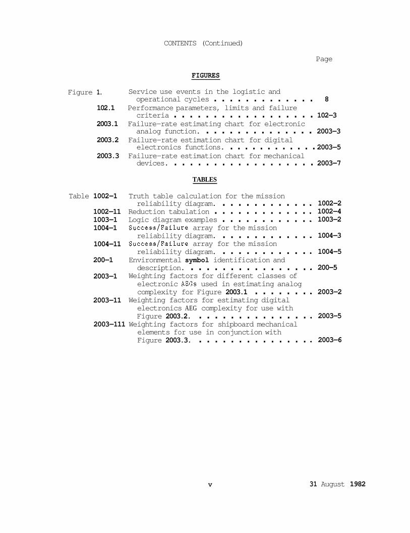
CONTENTS (Continued)
Page
FIGURES
Figure 1. Service use events in the logistic and operational cycles . . . . . . . . . . . . . 8
criteria . . . . . . . . . . . . . . . . . . 102-3 analog function. . . . . . . . . . . . . . . 2003-3 electronics functions. . . . . . . . . . . . . 2003-5 devices. . . . . . . . . . . . . . . . . . . 2003-7
102.1 Performance parameters, limits and failure
2003.1 Failure-rate estimating chart for electronic
2003.2 Failure-rate estimation chart for digital
2003.3 Failure-rate estimation chart for mechanical
TABLES
Table 1002-1 Truth table calculation for the mission reliability diagram. . . . . . . . . . . .
1002-11 Reduction tabulation . . . . . . . . . . . . 1003-1 Logic diagram examples . . . . . . . . . . . 1004-1
reliability diagram. . . . . . . . . . . . 1004-11
reliability diagram. . . . . . . . . . . . 200-1 Environmental symbol identification and
2003-1
Success/Failure array for the mission
Success/Failure array for the mission
description. . . . . . . . . . . . . . . . electronic AEGs used in estimating analog
Weighting factors for different classes of
complexity for Figure 2003.1 . . . . . . .
Figure 2003.2. . . . . . . . . . . . . . . elements for use in conjunction with Figure 2003.3. . . . . . . . . . . . . . .
2003-11 Weighting factors for estimating digital electronics AEG complexity for use with
2003-111 Weighting factors for shipboard mechanical
1002-2 1002-4 1003-2
1004-3
1004-5
200-5
2003-2
2003-5
2003-6
V 31 August 1982
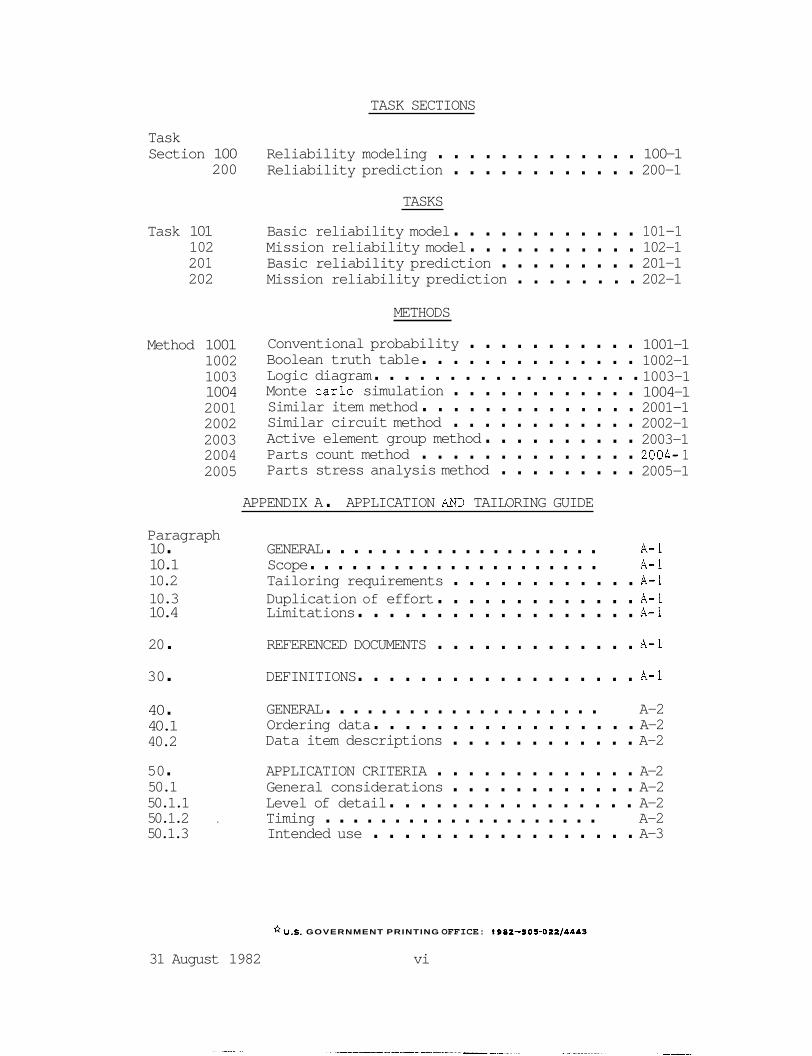
TASK SECTIONS
Task Section 100 Reliability modeling . . . . . . . . . . . . . 100-1
200 Reliability prediction . . . . . . . . . . . . 200-1 TASKS
Task 101 Basic reliability model . . . . . . . . . . . . 101-1 102 Mission reliability model . . . . . . . . . . . 102-1 20 1 Basic reliability prediction . . . . . . . . . 201-1 202 Mission reliability prediction . . . . . . . . 202-1
METHODS
Method 1001 1002 1003 1004 200 1 2002 2003 2004 2005
Conventional probability . . . . . . . . . . . Boolean truth table . . . . . . . . . . . . . . Logic diagram . . . . . . . . . . . . . . . . . . Monte carlo simulation . . . . . . . . . . . . Similar item method . . . . . . . . . . . . . . Similar circuit method . . . . . . . . . . . . Active element group method . . . . . . . . . . Parts count method . . . . . . . . . . . . . . Parts stress analysis method . . . . . . . . .
1001-1 1002-1 1003-1 1004-1 2001-1 2002-1 2003-1 2004- 1 2005-1
APPENDIX A . APPLICATION AND TAILORING GUIDE
Paragraph 10 . GENERAL . . . . . . . . . . . . . . . . . . . . A-1 10.1 Scope . . . . . . . . . . . . . . . . . . . . . A-1 10.2 Tailoring requirements . . . . . . . . . . . . A-1 10.3 Duplication of effort . . . . . . . . . . . . . A-1 10.4 Limitations . . . . . . . . . . . . . . . . . . A-1 20 . REFERENCED DOCUMENTS . . . . . . . . . . . . . A-1 30 . DEFINITIONS . . . . . . . . . . . . . . . . . . A-1 40 . 40.1 40.2
GENERAL . . . . . . . . . . . . . . . . . . . . A-2 Ordering data . . . . . . . . . . . . . . . . . A-2 Data item descriptions . . . . . . . . . . . . A-2
50 . APPLICATION CRITERIA . . . . . . . . . . . . . A-2 50.1 General considerations . . . . . . . . . . . . A-2 50.1.1 Level of detail . . . . . . . . . . . . . . . . A-2 50.1.2 . Timing . . . . . . . . . . . . . . . . . . . . A-2 50.1.3 Intended use . . . . . . . . . . . . . . . . . A-3
*U.S. GOVERNMENT PRINTING OFFICE: 1982.50 5.022/4443
31 August 1982 vi

MIL-STD-756B I8 NOVEMBER 1981
SUPERSEDING MIL-STD-756A 15 MAY 1963
MILITARY STANDARD
RELIABILITY MODELING AND PREDICTION
AMSC N3125 FSC RELl

MIL-STD-756B
DEPARTMENT OF DEFENSE Washington, DC 20301
RELIABILITY MODELING AND PREDICTION
MIL-S TD- 7 56B
1. This Military Standard is approved for use by all Departments and Agencies of the Department of Defense.
2. Beneficial comments (recommendations, additions, deletions) and any pertinent data which may be of use in improving this document should be addressed to: Commanding Officer, Engineering Specifications
Lakehurst, New Jersey 08733, by using the self-addressed Standardization - Document Improvement Proposal (DD Form 1426) appearing at the end of this document or by letter.
and Standards Department (Code 93), Naval Air Engineering Center, r
a

MIL-STD-756B
FOREWORD
R e l i a b i l i t y p r e d i c t i o n i s an e s s e n t i a l func t ion i n eva lua t ing a des ign from concept through development and i n c o n t r o l l i n g changes dur ing product ion. P r e d i c t i o n provides a r a t i o n a l b a s i s f o r des ign dec i s ions such as t h e choice between a l t e r n a t i v e concepts , choice of p a r t q u a l i t y levels, d e r a t i n g t o be appl ied , use of proven ve r sus s tate- of- the- art techniques, and o the r f a c t o r s .
It i s e s s e n t i a l t h a t common ground r u l e s be e s t a b l i s h e d f o r techniques and d a t a sources used i n t h e formulat ion of r e l i a b i l i t y models and p r e d i c t i o n s s o t h a t they may be appl ied and i n t e r p r e t e d uniformly. s tandard e s t a b l i s h e s procedures and ground r u l e s intended t o achieve t h i s purpose.
It must be recognized t h a t r e l i a b i l i t y p r e d i c t i o n is a b e s t estimate of t h e r e l i a b i l i t y a n t i c i p a t e d from a given design w i t h i n d a t a l i m i t a t i o n s and t h e ex t en t of i t e m d e f i n i t i o n . A proper ly performed r e l i a b i l i t y p r e d i c t i o n i s inva luab le t o those r e spons ib l e f o r making program dec i s ions regard ing t h e f e a s i b i l i t y and adequacy of a des ign approach.
This
R e l i a b i l i t y p r e d i c t i o n s are gene ra l ly based on experience d a t a from similar i t e m s , o r t h e i r components, used i n a s a m e o r similar manner. Extreme cau t ion must be exerc ised i n a s c e r t a i n i n g t h e s i m i l a r i t y of o t h e r i t e m s and t h e degree of s i m i l a r i t y i n t h e cond i t i ons of use. s tandard emphasizes v e r i f i c a t i o n and j u s t i f i c a t i o n of t h e v a l i d i t y and a p p l i c a b i l i t y of d a t a sources t o t h e p repa ra t ion of p r e d i c t i o n s .
This
The n e c e s s i t y f o r determining t h e c o s t s of achiev ing and s u s t a i n i n g t h e r e l i a b i l i t y of an i t e m r e q u i r e s t h a t r e l i a b i l i t y be considered from two pe r spec t ives , r e l i a b i l i t y as a measure of ope ra t iona l e f f e c t i v e n e s s (Mission R e l i a b i l i t y ) and r e l i a b i l i t y as a measure of ownership c o s t (Basic R e l i a b i l i t y ) . modes of ope ra t ion t o improve Mission R e l i a b i l i t y i nva r i ab ly decreases Basic R e l i a b i l i t y and inc reases procurement and l o g i s t i c support c o s t s . This s tandard addresses Mission R e l i a b i l i t y p r e d i c t i o n and Basic R e l i a b i l i t y p r e d i c t i o n as s e p a r a t e but companion p r e d i c t i o n s both of which are e s s e n t i a l t o adequately quan t i fy t h e r e l i a b i l i t y of an i t e m .
The inco rpora t ion of redundancies and a l t e r n a t e
The need f o r updat ing a given p r e d i c t i o n w i l l vary from program t o program and cannot be p r e c i s e l y e s t a b l i s h e d i n a genera l s tandard . Updating w i l l depend p r imar i ly on t h e degree t o which t h e i t e m has been def ined , and t h e a v a i l a b i l i t y of p e r t i n e n t d a t a . Provis ions should be made f o r r e l i a b i l i t y p r e d i c t i o n updates a t a l l des ign review p o i n t s and o t h e r major program mi les tones .
iii
P a r agr ap h
MIL-STD-756B
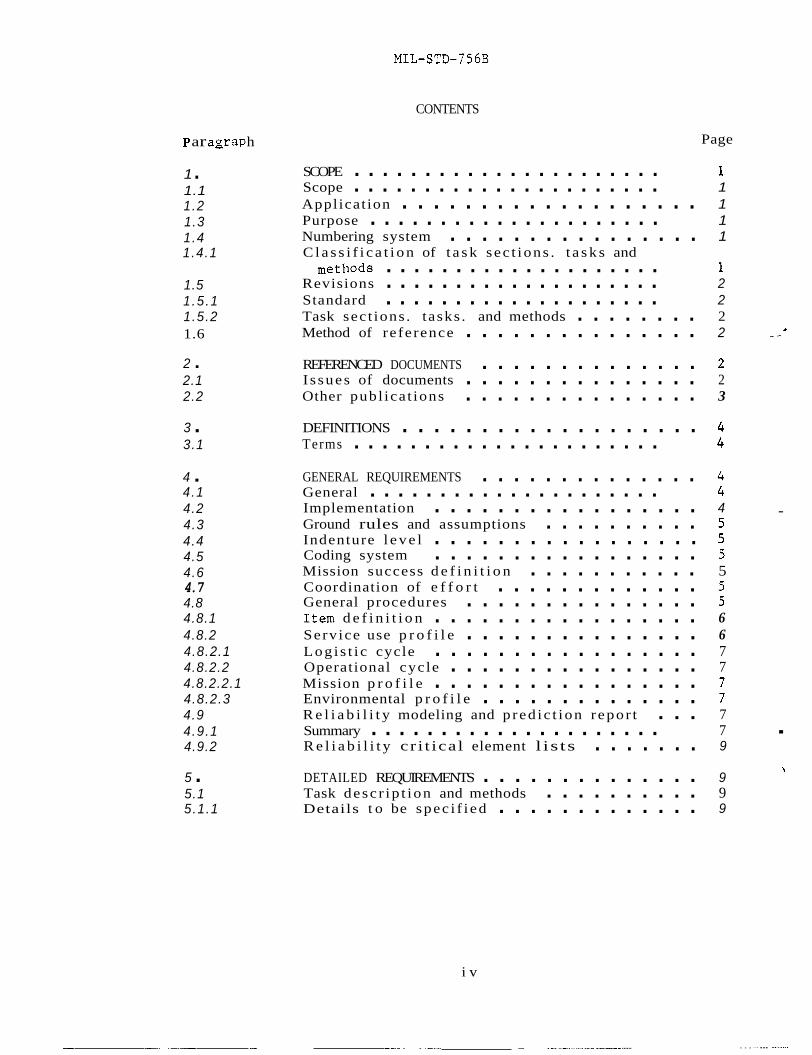
CONTENTS
Page
1 . 1.1 1.2 1.3 1.4 1.4.1
1.5 1 .5 .1 1.5.2 1.6
2 . 2.1 2.2
3 . 3.1
4 . 4.1 4.2 4.3 4.4 4.5 4.6 4.7 4.8 4.8.1 4.8.2 4.8.2.1 4.8.2.2 4.8.2.2.1 4.8.2.3 4.9 4.9.1 4.9.2
5 . 5.1 5.1.1
SCOPE . . . . . . . . . . . . . . . . . . . . . . 1 Scope . . . . . . . . . . . . . . . . . . . . . . 1 Applicat ion . . . . . . . . . . . . . . . . . . . 1 Purpose . . . . . . . . . . . . . . . . . . . . . 1 Numbering system . . . . . . . . . . . . . . . . 1 C l a s s i f i c a t i o n of t a s k sec t ions . t a s k s and
Revisions . . . . . . . . . . . . . . . . . . . . 2 Standard . . . . . . . . . . . . . . . . . . . . 2 Task sec t ions . tasks . and methods . . . . . . . . 2 Method of reference . . . . . . . . . . . . . . . 2 _ a
REFERENCED DOCUMENTS . . . . . . . . . . . . . . 2 I s sues of documents . . . . . . . . . . . . . . . 2 Other publ ica t ions . . . . . . . . . . . . . . . 3
methods . . . . . . . . . . . . . . . . . . . . 1
3
DEFINITIONS . . . . . . . . . . . . . . . . . . . 4 Terms . . . . . . . . . . . . . . . . . . . . . . 4
GENERAL REQUIREMENTS . . . . . . . . . . . . . . 4 General . . . . . . . . . . . . . . . . . . . . . 4 Implementation . . . . . . . . . . . . . . . . . 4 .
Ground rules and assumptions . . . . . . . . . . 5 Indenture l e v e l . . . . . . . . . . . . . . . . . 5 Coding system . . . . . . . . . . . . . . . . . 5 Mission success d e f i n i t i o n . . . . . . . . . . . 5 Coordination of e f f o r t . . . . . . . . . . . . . 5 General procedures . . . . . . . . . . . . . . . 5 I t e m d e f i n i t i o n . . . . . . . . . . . . . . . . . 6 Service use p r o f i l e . . . . . . . . . . . . . . . 6 Logis t i c cycle . . . . . . . . . . . . . . . . . 7 Operational cycle . . . . . . . . . . . . . . . . 7 Mission p r o f i l e . . . . . . . . . . . . . . . . . 7 Environmental p r o f i l e . . . . . . . . . . . . . . 7 R e l i a b i l i t y modeling and p red ic t ion r epor t . . . 7 Summary . . . . . . . . . . . . . . . . . . . . . 7 R e l i a b i l i t y cr i t ical element l is ts . . . . . . . 9
DETAILED REQUIREMENTS . . . . . . . . . . . . . . 9 Task desc r ip t ion and methods . . . . . . . . . . 9 Details t o be spec i f i ed . . . . . . . . . . . . . 9
. \
i v
... I ... - __ -.___ --. . . ...... ......_....I.I ._I--. ......

MIL-STD-756B
CONTENTS (Continued)
Page
FIGURES
Figure 1 . Figure 102.1 Performance parameters. l i m i t s and f a i l u r e
Serv ice use events i n t h e l o g i s t i c and ope ra t iona l cyc l e s . . . . . . . . . . . . . . a
cr i ter ia . . . . . . . . . . . . . . . . . . . 102-3
Figure 2003.1 Fa i lu re- ra t e es t imat ing c h a r t f o r e l e c t r o n i c analog func t ion . . . . . . . . . . . . . . . 2003-3
Figure 2003.2 Fa i lu re- ra t e e s t ima t ion c h a r t f o r d i g i t a l e l e c t r o n i c s func t ions . . . . . . . . . . . . 2003-5
Figure 2003.3 F a i l u r e- r a t e es t imat ion c h a r t f o r mechanical devices . . . . . . . . . . . . . . . . . . . 2003-7
TASK SECTIONS
Task Sec t ion 100 R e l i a b i l i t y modeling . . . . . . . . . . . . . . 100-1
200 R e l i a b i l i t y p r e d i c t i o n . . . . . . . . . . . . . 200-1
TASKS
Task 101 Basic r e l i a b i l i t y model . . . . . . . . . . . . 101-1
202 Mission r e l i a b i l i t y p r e d i c t i o n . . . . . . . . . 202-1
102 Mission r e l i a b i l i t y model . . . . . . . . . . . 102-1 201 Basic r e l i a b i l i t y p r e d i c t i o n . . . . . . . . . . 201-1
METHODS
Method 1001 1002 1003 1004 2001 2002 2003 2004 2005
Conventional p r o b a b i l i t y . . . . . . . . . . . . Boolean t r u t h t a b l e . . . . . . . . . . . . . . Logic diagram . . . . . . . . . . . . . . . . . Monte c a r l o s imula t ion . . . . . . . . . . . . . Simi lar i t e m method . . . . . . . . . . . . . . Simi l a r c i r c u i t method . . . . . . . . . . . . . Active element group method . . . . . . . . . . P a r t s count method . . . . . . . . . . . . . . P a r t s stress a n a l y s i s method . . . . . . . . . .
1001-1 1002-1 1003-1 1004-1 2001-1 2002-1 2003-1 2004-1 2005-1
V

MIL-STD-756B
Paragraph 10 . 10.1 10.2 10.3 10.4
20 . 30 . 40 . 40.1 40.2
50 . 50.1 50.1.1 50.1.2 50.1.3
CONTENTS (Continued)
APPENDIX A . APPLICATION AND TAILORING GUIDE
GENERAL . . . . . . . . . . . . . . . . . . . . Scope . . . . . . . . . . . . . . . . . . . . . Ta i lo r ing requirements . . . . . . . . . . . . . Duplicat ion of e f f o r t . . . . . . . . . . . . . Limi ta t ions . . . . . . . . . . . . . . . . . . REFERENCED DOCUMENTS . . . . . . . . . . . . . . DEFINITIONS
GENEWL . . . . . . . . . . . . . . . . . . . . Ordering d a t a . . . . . . . . . . . . . . . . . Data i t e m d e s c r i p t i o n s . . . . . . . . . . . . APPLICATION CRITERIA . . . . . . . . . . . . . General cons ide ra t ions . . . . . . . . . . . . Level of de t a i l . . . . . . . . . . . . . . . . Timing . . . . . . . . . . . . . . . . . . . . . Intended use . . . . . . . . . . . . . . . . .
vi
.... ._
A- 1 A- 1 A-1 A-1 A- 1
A-1
A- 1
A-2 A-2 A-2
A-2 A- 2 A-2 A-2 A-3
.

MIL-STD-756B
1. SCOPE
1.1 Scope. This standard establishes uniform procedures and ground rules for the preparation of Mission Reliability and Basic Reliability models and predictions for electronic, electrical, electro- mechanical, mechanical, and ordnance systems and equipments, hereinafter referred to as items. Item complexity may range from a complete weapon system to the simplest subdivision of a system. Reliability Prediction is as a design tool to provide relative measures of item reliability to design decisions. when applying and translating the absolute value of the Reliability Prediction to measures of Field Reliability.
The primary value of
Great caution must be used
1.2 Application. The requirements and procedures established by this standard may be applied to any Department of Defense procurement for item development and production. requirements herein will need to be applied to every program or program phase. Procuring activities shall tailor the requirements. of this standard to the minimum needs of each procurement and shall encourage contractors to submit cost effective tailoring recommendations.
It is not intended that all the
1.3 Purpose. Reliability modeling and prediction is a methodology for estimating an item's ability to meet specified reliability requirements. that an item will perform its required functions during the mission. Basic Reliability prediction estimates the demand for maintenance and logistic support caused by an item's unreliability. the two predictions provide a basis for identifying areas wherein special emphasis or attention is needed, and for comparing the ownership cost- effectiveness of various design configurations. The two predictions may also be used as a basis for the apportionment (allocation) of ownership cost and operational effectiveness requirements to various subdivisions.
A Mission Reliability prediction estimates the probability A
When used in combination,
1.4 Numbering system. Task sections, tasks, and methods are numbered sequentially as they are introduced into this standard in accordance with the following classification system.
1 .4 .1 Classification of task sections, tasks, and methods.
100 - Reliability modeling task section 101 to 199 - Reliability modeling tasks
1001 to 1999 - Reliability modeling methods 200 201 to 299 - Reliability prediction tasks
2001 to 2999 - Reliability prediction methods - Reliability prediction task section
1

MIL-STD-75 6B
1.5 Revisions.
1.5.1 Standard. Any gene ra l r e v i s i o n of t h i s s tandard which r e s u l t s i n a r e v i s i o n of s e c t i o n s 1, 2, 3 or 4 w i l l b e i nd ica t ed by a r e v i s i o n le t ter a f t e r t h i s s tandard number, toge ther w i th t h e d a t e of r ev i s ion .
1.5.2 Task s e c t i o n s , t a sks , and methods. Revisions are numbered consecut ive ly ind ica t ed by a le t ter fol lowing t h e number. For example; f o r t a s k 101, t h e f i r s t r e v i s i o n is 101A, t h e second r e v i s i o n i s 101B. When t h e Basic Document is rev i sed , those requirements n o t a f f ec t ed by change r e t a i n t h e i r e x i s t i n g da te .
1.6 Method of re ference . The t a sks and methods contained h e r e i n s h a l l be referenced by spec i fy ing:
a. This s tandard number b. Task number(s) c. Method number(s) d. Other d a t a as c a l l e d f o r i n t h e i n d i v i d u a l
t a sk o r method
2. REFERENCED DOCUMENTS
2 . 1 I s sues of documents. The fol lowing documents of t h e i s s u e i n e f f e c t on d a t e of i n v i t a t i o n f o r b i d s o r r eques t f o r proposal , are referenced i n t h i s s tandard f o r information and guidance.
STANDARDS
M i l i t a r y
MIL-STD-280 Def in i t i ons of I t e m Levels , I t e m Exchangeabi l i ty , Models and Related T e r m s
MIL-STD-470 Main ta inab i l i t y Program Requirements
MIL-STD-721 Def in i t i ons of Terms f o r R e l i a b i l i t y and Main ta inab i l i t y
MIL-STD-780 Work Unit Codes f o r Aeronaut ical Equipment; Uniform Numbering System
MIL-STD-785 R e l i a b i l i t y Program f o r Systems and Equipment Development and Product ion
MIL-STD-881 Work Breakdown S t r u c t u r e s f o r Defense Material I t e m s
MIL-STD-882 System Sa fe ty Program Requirements

MIL-STD-756B
STANDARDS (Cont inued)
M i l i t a r y (Continued)
MIL-S TD- 1 388 Log i s t i c s Support Analysis
MIL-STD-1591 On A i r c r a f t , Fau l t Diagnosis, Subsystems, Analysis /Synthesis of
MIL-STD-1670 Environmental Criteria and Guidel ines f o r A i r - Launched Weapons
MIL-STD-2072 S u r v i v a b i l i t y , A i r c r a f t ; Establishment and Conduct of Programs For
MIL-STD-2080 Maintenance P lan Analysis f o r A i r c r a f t and Ground Support Equipments
HANDBOOKS
Mil i tarv
MIL-HDBK-2 17 R e l i a b i l i t y P red ic t ion of E lec t ron ic Equipment
MIL-HDBK-251 Re l i ab i l i t y /Des ign Thermal Applicat ions
(Copies of s p e c i f i c a t i o n s , s tandards , drawings, and pub l i ca t ions requi red by con t r ac to r s i n connection wi th s p e c i f i c procurement func t ions should be obtained from t h e procuring a c t i v i t y o r as d i r e c t e d by t h e con t r ac t ing o f f i c e r . )
PUBLICATIONS
Naval Sea Systems Command
NAVORD OD 44622 R e l i a b i l i t y Data Analysis and I n t e r p r e t a t i o n Volume 4
% (Applicat ion f o r copies should be addressed t o : Commanding Of f i ce r ,
Naval Ship Weapon Systems Engineering S t a t i o n (Code 5743), Po r t Hueneme, CA 93043.)
I
2.2 Other pub l i ca t ions . The fol lowing documents are
S p e c i f i c requirements f o r use of t h e s e o r o t h e r p o t e n t i a l sources of r e l i a b i l i t y d a t a t h a t may be used i n conjunct ion wi th t h i s s tandard. d a t a sources must be spec i f i ed by t h e procuring a c t i v i t y .
3
MIL-STD-7 5 6B
RADC-TR- 7 3-248 (AD- 7 68 61 9)
Dormancy and Power On-Off Cycling Effects on Electronic Equipment and Part Reliability
RADC-TR-74-269 Effects of Dormancy on Nonelectronic (AD/A-O02838) Components and Materials
LC- 7 8- 1 Storage Reliability of Missile Material Program, Missile Material Reliability Handbook Parts Count Prediction
(AD/A-053403)
(.Application for copies should be addressed to the National Technical Information Service, U.S. Department of Commerce, 5385 Port Royal Road, Springfield , VA 22161. )
GIDEP Government Industry Data Exchange Program, Summaries of Failure Rates
(Application for copies should be addressed to the Fleet Analysis Center, GIDEP Operations Center, Naval Weapons Station, Seal Beach, Corona Annex, Corona, CA 91720.)
NPRD-1 Nonelectronic Parts Reliability Data, 1978
(Application for copies should be addressed to the Reliability Analysis Center, RADC/RBRAC, Griffiss AFB, NY 13441.)
3. DEFINITIONS
3.1 Terms, Terms used in this document are as defined in MIL-STD-280 and MIL-STD-721.
4 . GENERAL REQUIREMJINTS
4.1 General. Reliability modeling and prediction shall be planned and performed in accordance with the general requirements of this standard and the task(s) and method(s) specified by the procuring activity .
4.2 Implementation. Reliability modeling and prediction shall be initiated early in the configuration definition stage to aid in the evaluation of the design and to provide a basis for item reliability allocation (apportionment) and establishing corrective action priorities. Reliability models and predictions shall be updated when there is a significant change in the item design, availability of design details, environmental requirements, stress data, failure rate data, or service use profile. A planned schedule for updates shall be specified by the procuring activity.

MIL-S TD- 7 56B
4.3 Ground r u l e s and assumptions. The con t r ac to r s h a l l develop ground r u l e s and a n a l y s i s assumptions. The ground r u l e s s h a l l i d e n t i f y t h e r e l i a b i l i t y modeling and p r e d i c t i o n approach, t h e lowest i nden tu re level t o be analyzed, and inc lude a d e f i n i t i o n of mission success f o r t h e i t e m f n terms of performance c r i t e r i a and al lowable l i m i t s . Ground r u l e s and a n a l y s i s assumptions are not i n f l e x i b l e and may be added, modified, o r de l e t ed i f requfrements change. Ground r u l e s and a n a l y s i s assumptions s h a l l be documented and included i n t h e r e l i a b i l i t y modeling and p r e d i c t i o n r e p o r t .
4.4 Indenture l e v e l . The indenture level a p p l i e s t o t h e i t e m hardware o r func t iona l l e v e l a t which t h e i t e m conf igura t ion i s defined. Unless o therwise s p e c i f i e d , t h e con t r ac to r s h a l l e s t a b l i s h t h e lowest i nden tu re level of a n a l y s i s us ing t h e fol lowing gufde l ines :
a . The lowest level spec i f i ed f o r t h e F a i l u r e Mode, E f fec t s , and C r i t i c a l f t y Analysis (FMECA) t o ensure cons is tency and al low cross re ferenc ing .
b. The s p e c i f i e d o r fntended maintenance and r e p a i r level f o r hardware elements of t h e i t e m .
4.5 Coding system. For c o n s i s t e n t i d e n t i f i c a t i o n of i t e m func t fons and hardware elements, t h e con t r ac to r s h a l l adhere t o a coding system based upon t h e hardware breakdown s t r u c t u r e , work u n i t code numbering system o f MIZ-STD-780, o r o t h e r similar uniform numbering system. and func t iona l b lock diagram numbering system t o provide complete v i s i b i l i t y of each modeled element and i t s r e l a t i o n s h i p to t h e i t e m .
The coding system s h a l l be c o n s i s t e n t wi th t h e FMECA ( i f requi red)
4 . 6 Mission success d e f i n i t i o n . The con t r ac to r s h a l l develop genera l s tatements of i t e m mission success i n terms of performance and al lowable l i m f t s f o r each s p e c i f i e d output . Mission success d e f i n i t i o n s s h a l l be included i n t h e ground r u l e s d iscussed i n 4.3.
4 .7 Coordination of e f f o r t . R e l i a b i l i t y and o t h e r o rgan iza t iona l elements s h a l l make coimcident performance and u s e of t h e r e i e a b i l i t y models and p red ic t ions . requirements t o perform and use t h e r e l i a b i l i t y models and p r e d i c t i o n s i n support o f a r e l i a b i l i t y program i n accordance wi th MIL-STD-785, m a i n t a i n a b i l f t y program i n accordance wi th MIL-STD-470, s a f e t y program i n accordance w i t h MIL-STD-882, s u r v i v a b i l i t y and v u l n e r a b i l i t y program i n accordance wi th MIL-STD-2072, l o g i s t i c s support a n a l y s i s i n accordance wi th MIL-STD-1388, maintenance plan a n a l y s i s (MPA) i n accordance wi th MIL-STD-2080, f a u l t diagrams a n a l y s i s en general accordance wi th MIL- STD-1591, and o t h e r con t r ac tua l provis ions .
Considerat ion s h a l l be given t o t h e
4.8 General procedure. The s t e p s set f o r t h below d e f i n e t h e procedure f o r developing a r e l 2 a b i l i t y model and performing a r e l i a b i l i t y pred ic t fon . E f f o r t t o develop t h e information f o r t h e s t e p s below s h a l l be c l o s e l y c o o r d h a t e d wi th r e l a t e d program a c t i v i t i e s (such as des ign engineer ing , system engineer ing , ma in t a inab i l i t y , and l o g i s t i c s ) t o minbqize d u p l i c a t i o n s and t o a s s u r e cons is tency and co r rec tnes s .
5

MIL-STD-756B
a .
b.
C .
d.
e.
f .
g *
h.
i.
j.
Define t h e i t e m f o r which t h e p r e d i c t i o n is app l i cab le (see 4.8.1).
Define t h e service use ( l i f e cyc le) f o r which i t e m r e l i a b i l i t y w i l l be modeled and p red ic t ed ( see 4.8.2).
Define t h e i t e m r e l i a b i l i t y block diagrams ( see 2.3 of Task Sec t ion 100).
Define t h e mathematical models f o r computing i t e m r e l i a b i l i t y (see 2.4 of Task Sec t ion 100).
Define t h e p a r t s of t h e i t e m ( s ee 2.2 of Task Sec t ion 200).
Define t h e environmental d a t a ( s ee 2.3 of Task Sec t ion 200).
Define t h e stress d a t a ( see 2.4 of Task Sec t ion 200).
Define t h e f a i l u r e d i s t r i b u t i o n (see 2.5 of Task Sec t ion 200).
Define t h e f a i l u r e rates (see 2.6 of Task Sec t ion 200).
Compute t h e i t e m r e l i a b i l i t y ( s ee 2 . 7 of Task Sec t ion 200).
4.8.1 I t e m d e f i n i t i o n . I t e m d e f i n i t i o n s h a l l inc lude performance requirements and hardware concept t o t h e ex t en t known a t t h e t i m e t h e model and p r e d i c t i o n are prepared. C h a r a c t e r i s t i c s of t h e i t e m s h a l l b e s t a t e d i n terms of range, a l t i t u d e , speed, maneuverabi l i ty , environmental condi t ions , power, o r such o t h e r parameters as may be app l i cab le . The manner i n which t h e i t e m and i t s subdiv is ion ope ra t e i s usua l ly expressed by means of func t iona l diagrams whech can become t h e b a s i s f o r t h e r e l e a b e l i t y block dlagrams (see 2.3 of Task Sec t ion 100). Normally, t h e i m i t i a l i t e m def%ni t+on used f o r t h e f e a s i b i l i t y p r e d i c t i o n w i l l be l ack ing several d e t a i l s and w i l l r e q u i r e c e r t a i n assumptions as t o environmental condi t ions , design conf igu ra t ion , etc. The i t e m d e f i n i t i o n s h a l l be r e f i n e d and updated as more information becomes a v a i l a b l e t o support t h e pre l iminary design p red ic t ion , and subsequently, t h e d e t a i l e d des ign p red ic t ion . A s t h e i t e m d e s c r i p t i o n i s p rog res s ive ly updated, h igher l e v e l s of accuracy w i l l b e a t t a i n e d f o r p r e d i c t i o n r e s u l t s .
4.8.2 Service u s e p r o f i l e . The service use ( l i f e cyc le) p r o f i l e o r po r t ion thereof t o be used f o r r e l i a b i l i t y modeling and p red ic t ron s h a l l e i t h e r be proveded by t h e procuring a c t i v i t y o r s p e c i f i e d f o r c o n t r a c t o r prepara t ion . The service use p r o f i l e is a thorough d e s c r i p t i o n of a i l events and environments assoc ia ted wi th an i t e m from

MIL-STD-756B
f inal factory acceptance through i t s terminal expenditure or removal from inventory. storage, test and checkout, operational deployment, etc., is addressed.
U e 1 i l lu s t r a t e s the major service use events to be considered i n the logis t ic and operational cycles. The profi le depicts expected time spans, environments, operating modes (including standby and ready modes), e tc . , for each event. cycles, mission profiles, and environmental profiles i s used t o develop the service use proffle.
Each s ignif icant servtce use event, such as transportation,
Information from logis t ic cycles, operational
4.8.2.1 Logistic cycle. The logis t ic cycle shall describe the expected duration and sequence of events which maintain, transport, and s tore an item t o assure operational availabili ty.
4.8.2.2 Operational cycle. The operational cycle shall describe the expected duration and sequence of events of the period from an item's assignment to an operational user through expenditure or return to some phase of the logis t ic cycle.
4.8.2.2.1 Mission profile. The mission profi le shall describe events and conditions associated w i t h a specific operational usage of an item. profi le shall depict the time spans of the events and operational conditions t o be anticipated. Multiple mission profiles may be required t o adequately describe an item's multimission capabili t ies.
A mission profi le i s one segment o f the operational cycle: The
4.8.2.3 Environmental profile. The environmental profi le sha l l describe the specif ic natural and induced environments (nominal and worst case) w i t h the operations, events, and functions described by the logis t ic and operational cycles. associated environmental profile.
Each mission profi le shall have an
4.9 Re1 iabi 1 i t y model i ng and prediction report. The r e l i ab i l i t y models and r e l i a b i l i t y Dredictions shall be documented i n a report that ident i f ies the level of' analysis, summarizes the results, documents the data sources and techniques used i n performing the analysis, and includes the item definit ion narrative, resultant analysis data, worksheets, ground rules and assumptions. Interim reports shall be available a t each design review to provide comparisons of a1 ternative designs and t o highlight h i g h fa i lure rate elements of the item design, potential mission r e l i ab i l i t y single fa i lure points, and proposed design corrections or improvements. The final report shall re f lec t the final design and provide identification of high fa i lure ra te elements, overstressed parts, and mission r e l i a b i l i t y single fa i lure points which could not be eliminated from the design. EIhen submitting a report applicable for an Expl oratory/Advanced Devel opment Model , and prediction report i s required.
a simp1 i f i ed re1 i abi 1 i ty model i ng
4.9.1 Summary. The report shall contain a summary which provides the contractor 's conclusions and recommendations based upon the analysis. Contractor interpretation and comments concerning the analysis and the in i t ia ted as recomnended actions for the elimination or reduction
7

MIL-STD-756B
TRANSPORT U
LOGISTIC CYCLE
.
PROCUREMENT- U PACKAGING
TRANSPORT
MAINTENANCE r,
I I I I I I I I I
REPETITIVE CYCLES I FOR VARIOUS TYPES I OF STORAGE AND VARIOUS GEOGRAPHIC I AREAS OF STORAGE I
I I
STORAGE
TRANSPORT
OPERATIONAL CYCLE
- - p q
* TRANSPORT 5 DISPOSAL
Figure 1. Service Use Events in the Logistic and Operational Cycles.
8
. . ~ - x- I- . . . .._-._.._I- ... .-

MIL-STD-756B
of f a i l u r e r i s k s s h a l l be included. major problems de tec ted during t h e a n a l y s i s s h a l l be provided i n t h e f i n a l r epo r t . A l i s t of hardware o r func t iona l elements of t h e i t e m omitted from t h e r e l i a b i l i t y models and r e l i a b i l i t y p r e d i c t i o n s s h a l l be included wi th r a t i o n a l e f o r each element 's exclusion.
A des ign eva lua t ion summary of
4.9.2 R e l i a b i l i t y c r i t i ca l element l ists. R e l i a b i l i t y c r i t i c a l elements of t h e i t e m ex t r ac t ed from t h e r e l i a b i l i t y modeling and r e l i a b i l i t y p r e d i c t i o n e f f o r t s h a l l be l i s t e d and included i n t h e summary. R e l i a b i l i t y c r i t i ca l elements inc lude h igh f a i l u r e ra te elements , ove r s t r e s sed p a r t s (i .e. , exceed e s t ab l i shed p a r t s d e r a t i n g c r i t e r i a ) , and mission r e l i a b i l i t y s i n g l e f a i l u r e po in t s .
5. DETAIL REQUIREMENTS
5 .1 Task d e s c r i p t i o n and methods. The d e t a i l t a s k s and methods f o r prepar ing r e l i a b i l i t y models and performing r e l i a b i l i t y p r e d i c t i o n s follow. The t a s k d e s c r i p t i o n s and methods are d iv ided i n t o two genera l s ec t ions : Sec t ion 100, R e l i a b i l i t y Modeling; and Sec t ion 200, R e l i a b i l i t y P red ic t ion .
5.1.1 Details t o be s p e c i f i e d . The "Details t o be Specif ied" paragraph under each Task Sec t ion i s intended f o r l i s t i n g t h e s p e c i f i c d e t a i l s , add i t i ons , modif icat ions, d e l e t i o n s , o r op t ions t o t h e requirements of t h e t a s k s covered by t h e s e c t i o n t h a t should be considered by t h e Prepar ing A c t i v i t y (PA) when t a i l o r i n g t h e t a s k d e s c r i p t i o n t o f i t program needs. be provided t h e c o n t r a c t o r f o r proper implementation of t h e t a sk .
"Details" annotated by an "(R)" ARE ESSENTIAL and s h a l l
Custodians:
Navy - AS A i r Force - 1 7
Army - CR
Review Act iv i t i es : Army - EA, AR Navy - SHY 0s
Users : Army - AM Navy - EC National Secu r i ty Agency - NS Defense Mapping Agency - DMA
Prepar ing Ac t iv i ty : Navy - AS
P r o j e c t No. RELI-0001
9


MIL-STD-756B
TASK SECTION 100
RELIABILITY MODELING
1. DOCUMENTS REFERENCED I N TASK SECTION 100:
STANDARDS
MILITARY
MIL-STD-780 Work Unit Codes f o r Aeronaut ical Equipment; Uniform Numbering System
MIL-STD-881 Work Breakdown S t r u c t u r e s f o r Defense Material I t e m s
2. REQUIREMENTS
2 . 1 Basic R e l i a b i l i t y model. The Basic R e l i a b i l i t y model s h a l l c o n s i s t of a r e l i a b i l i t y block diagram and an a s soc i a t ed mathematical model. model which inc ludes elements of t h e i t e m intended s o l e l y f o r redundancy and a l t e r n a t e modes of opera t ion .
By d e f i n i t i o n , t h e Basic R e l i a b i l i t y model is an a l l series
2.2 Mission R e l i a b i l i t y model. The Mission R e l i a b i l i t y model s h a l l c o n s i s t of a r e l i a b i l i t y block diagram and an a s soc i a t ed mathematical model. intended u t i l i z a t i o n of t h e elements of t h e i t e m t o achieve mission success . Elements of t h e item intended f o r redundancy o r a l t e r n a t e modes of ope ra t ion s h a l l be modeled i n a p a r a l l e l con f igu ra t ion o r similar cons t ruc t app ropr i a t e t o t h e mission phase and mission a p p l i c a t i o n .
2.3 R e l i a b i l i t y block diagrams. R e l i a b i l i t y block diagram s h a l l be prepared t o show interdependencies among a l l elements (subsystems, equipments, etc.) o r func t iona l groups of t h e i t e m f o r i t e m success i n each service use event. t o show by concise visual shorthand t h e va r ious s e r i e s- p a r a l l e l block pornbinations (paths) t h a t resu l t 5n i t e m success . of t h e $tern's miss5on d e f i n i t i o n , and service use p r o f i l e is requi red t o produce t h e r e l i a b i l i t y diagram.
The Mission R e l i a b i l i t y model s h a l l be cons t ruc ted t o d e p i c t t h e
The purpose of t h e r e l s a b i l i t y block diagram i s
A complete understanding
2.3.1 Block diagram t i t l e . Each r e l i a b i l i t y block diagram s h a l l have a t i t l e inc luding i d e n t i f i c a t i o n of t h e i t e m , t h e mission i d e n t i f i c a t i o n o r po r t ion of t h e service use p r o f i l e addressed, and a d e s c r i p t i o n of t h e mode of ope ra t ion f o r which t h e p r e d i c t i o n is t o be performed.
2 . 3 . 2 Statement of condi t ions . Each r e l i a b i l i t y block diagram s h a l l inc lude a s tatement of condi t ions l i s t i n g a l l c o n s t r a i n t s which in f luence t h e choice of block p re sen ta t ion , t h e r e l i a b i l i t y parameters o r r e l i a b i l i t y v a r i a b l e s u t i l i z e d i n t h e a n a l y s i s , and t h e assumptions o r s i m p l i f i c a t i o n s u t i l i z e d t o develop t h e diagram. Once e s t a b l i s h e d , t h e s e cond i t i ons s h a l l be observed throughout t h e a n a l y s i s .
100- 1 TASK SECTION 100 18 November 1981

MIL- S TD- 75 6B
2.3.3 i n s p e c i f i c terms s t a t i n g exac t ly what t h e ca l cu la t ed r e l i a b i l i t y r ep re sen t s f o r t h e i t e m s as d i ag ramed and performing under t h e criteria presented i n t h e s tatement of condi t ions .
Statement of success . A statement of success s h a l l be def ined
2.3.4 a l o g i c a l o rde r which relates t h e sequence of events dur ing t h e prescr ibed ope ra t ion of t h e i t e m .
Order of t he diagram. The blocks i n t h e diagram s h a l l fol low
2.3.5 Block r ep resen ta t ion . The r e l i a b i l i t y block diagram s h a l l be drawn s o t h a t each element o r func t ion employed i n t h e i t e m can be i d e n t i f i e d . one element of func t ion contained i n t h e i t e m . b lock diagram s h a l l be configured i n series, p a r a l l e l , standby, o r combinations thereof as appropr ia te .
Each block of t h e r e l i a b i l i t y block diagram s h a l l r ep re sen t A l l b locks of t h e r e l i a b i l i t y
2.3.6 I d e n t i f i c a t i o n of blocks. Each block of t h e r e l i a b i l i t y block diagram s h a l l be i d e n t i f i e d . Diagrams conta in ing few blocks may have t h e f u l l i d e n t i f i c a t i o n w r i t t e n i n t h e block. blocks s h a l l use a c o n s i s t e n t and l o g i c a l code i d e n t i f i c a t i o n w r i t t e n f o r each block. The coding system s h a l l be based upon t h e work breakdown s t r u c t u r e of MIL-STD-881, work u n i t code numbering system of MIL-STD-780, o r o the r similar uniform i d e n t i f i c a t i o n system t h a t w i l l permit unambiguous t r a c e a b i l i t y of t h e r e l i a b i l i t y block t o i t s hardware (o r func t iona l ) equiva len t as def ined i n program documentation. The code s h a l l be i d e n t i f i e d i n a s e p a r a t e l i s t i n g .
Diagrams conta in ing many
2.3.6.1 Non-modeled elements. Hardware o r func t iona l elements of t h e i t e m which are not included i n t h e r e l i a b i l i t y model s h a l l be i d e n t i f i e d i n a sepa ra t e l i s t i n g u t i l i z i n g t h e coding system employed i n 2.3.6 of Task Sec t ion 100. Rat iona le f o r each element 's exc lus ion from t h e r e l i a b i l i t y model s h a l l be provided.
2.3.7 R e l i a b i l i t y v a r i a b l e . R e l i a b i l i t y v a r i a b l e s s h a l l be determined f o r each block and presented i n such a manner t h a t t h e a s s o c i a t i o n between t h e block and i ts v a r i a b l e is apparent . i s a number ( t ime, cyc les , events , e t c . ) used t o desc r ibe t h e du ra t ion of opera t ion requi red by each block t o perform i ts s t a t e d func t ion . This v a r i a b l e shall be used i n c a l c u l a t i n g t h e r e l i a b i l i t y of t h e block.
The r e l i a b i l i t y v a r i a b l e
2.3.8 Block diagram assumptions. Two types of assumptions s h a l l be used i n prepar ing r e l i a b i l i t y block diagrams: (1) t e c h n i c a l and (2) genera l . Technical assumptions may be d i f f e r e n t f o r each i t e m and f o r each mode of opera t ion . The t e c h n i c a l assumptions s h a l l be set f o r t h under t h e s tatement of condi t ions . The genera l assumptions are those app l i cab le t o a l l r e l i a b i l i t y block diagrams. It is no t necessary t o l i s t t h e genera l assumptions s t a t e d i n t h i s s tandard on t h e r e l i a b i l i t y block diagrams, provided re ference has been made t o t h i s paragraph. The fol lowing genera l assumptions s h a l l apply t o r e l i a b i l i t y block diagrams:
TASK SECTION 100 100-2 18 November 1981
___ ____ __- --I--- --- - - -

a.
b.
C .
d.
e.
2.3.8.1 sof tware
MIL-STD-756B
The blocks denote elements o r func t ions of t h e i t e m s t h a t are considered when eva lua t ing r e l i a b i l i t y and which have r e l i a b i l i t y v a l u e s a s soc i a t ed wi th them.
All l i n e s connect ing blocks have no r e l i a b i l i t y va lues . The l i n e s serve only t o g i v e order and d i r e c t i o n t o t h e diagram and do not r ep re sen t t h e wir ing c a b l e s and connectors a s soc i a t ed wi th t h e i t e m . s i n g l e block o r included as p a r t of t h e block f o r an element o r funct ion.
Cabling and connectors are incorpora ted i n t o a
A l l i n p u t s t o t h e i t e m are wi th in s p e c i f i c a t i o n l i m i t s .
F a i l u r e of any element o r func t ion denoted by a block i n t h e diagram w i l l cause f a i l u r e of t h e en t i re i t e m , except where a l t e r n a t i v e modes of ope ra t ion may be present .
Each element o r func t ion denoted by a block i n t h e diagram i s independent, wi th regard t o p r o b a b i l i t y of f a i l u r e , from a l l o t h e r blocks.
Software r e l i a b i l i t y assumption. The assumption t h a t a l l is completely r e l i a b l e s h a l l be s t a t e d i n i n s t ances when sof tware
r e l i a b i l i t y i s not incorporated i n t h e i t e m r e l i a b i l i t y p red ic t ion .
2.3.8.2 Human r e l i a b i l i t y assumption. The assumption t h a t a l l human elements are completely r e l i a b l e and t h a t no i n t e r f a c e problems occur between human elements and t h e item s h a l l be s t a t e d i n i n s t ances when human r e l i a b i l i t y i s not incorporated i n t h e i t e m r e l i a b i l i t y p red ic t ion .
2.4 Mathematical models. Models s h a l l be derived t o mathematical ly relate r e l i a b i l i t y block diagrams t o time-event r e l a t i o n s h i p s and f a i l u r e rate d a t a . The mathematical model s h a l l be capable of being r e a d i l y updated wi th iqfarmat ion r e s u l t i n g from r e l i a b i l i t y and o t h e r r e l e v a n t tests as w e l l as changes i n i t e m conf igura t ion , mission parameters and ope ra t iona l c o n s t r a i n t s .
The s o l u t i o n of t h e models will be t h e item pred ic t ed r e l i a b i l i t y .
3. 5.1.1).
Details t o be s p e c i f i e d by t h e Prepar ing Acf iv i ty (PA) (See The fol lowing are app l i cab le when Task 101 o r 102 are invoked:
a. Indenture level (4.4)
b. Software R e l i a b i l i t y App l i cab i l i t y (2.3.8.1 of Task Sec t ion 100).
c. Human R e l i a b i l i t y App l i cab i l i t y (2.3.8.2 of Task Sec t ion 100).
100-3 TASK SECTION 100 18 November 1981
MIL-STD-756B
(R) d. Modeling Method(s). An option is to allow contractor selection of the appropriate modeling method(s). methods may be applicable to different system components.
Different prediction
e. DI-R-7094 Reliability Mathematical Models should be specified when deliverable data is desired in conjunction with this task.
(R) f. Item definition (4.8.1).
(R) g. Service use profile (4.8.2).
TASK SECTION 100 18 November 1981 100-4
----- ---- - _. - ~

MIL-STD- 7 5 6B
TASK 101
BASIC RELIABILITY MODEL
1. PURPOSE/RATIONALE
1.1 the demand for maintenance and logistic support caused by an item and its component parts. redundancy or alternate modes of operation are modeled in series. Except for those instances in which there is neither redundancy nor alternate modes of operation provided f o r the item, the Basic Reliability model cannot be used to estimate Mission Reliability. However, both the Basic Reliability model and the Mission Reliability model are used in combination to compare the ownership cost-effectiveness of various design configurations and as a basis for apportionment (allocation) of ownership cost and operational effectiveness requirements to various subdivisions of an item.
A Basic Reliability model is a series model used for estimating
Accordingly, all elements of the item provided for
1.2 The basic information for the Basic Reliability model is derived from documentation identifying all equipments and associated quantities that comprise the item. As the proposed item design is firmed and comes under configuration control, the established configuration baseline should be the basis for the Basic Reliability model.
1 . 3 The Basic Reliability model should be developed to the level of detail (equipment, subassembly, or part level) for which information is available and for which failure rate, (or equivalent), data can be applied to evaluate the maintenance and logistic support impact of the item design.
1.4 the Basic Reliability model is used to develop mathematical expressions or computer programs which, with appropriate failure rate data, can provide apportionment, estimates and assessments of Basic Reliability.
Together with duty cycle and mission duration, information,
REQUIREMENT
2,l The contractor shall develop and maintain a Basic Reliability model based upon a defined item configuration. All equipments and associated quantities comprising the item shall be included in the model. All equipments, including those intended solely for item redundancy and alternate modes of operation, shall be modeled in series. A Basic Reliability block diagram shall be developed and maintained for the item with associated allocations and predictions in each reliability block. The Basic Reliability block diagram shall be keyed and traceable to the Mission Reliability model, functional block diagrams, schematics and drawings, and shall provide the basis for accurate mathematical representation of Basic Reliability. Nomenclature of elements o f the item used in the Basic Reliability block diagrams shall be consistent with that used in the Mission Reliability model, functional block diagrams, drawings and schematics, weight statements, power budgets and specifications.
101-1 TASK 101 18 November 1981


MIL-STD-756B
TASK 102
MISSION RELIABILITY MODEL
1. PURPOSE / RATIONALE
1.1 A Mission R e l i a b i l i t y model i s used f o r eva lua t ing complex s e r i e s- p a r a l l e l equipment arrangements which usua l ly e x i s t i n weapon systems.
2. MISSION RELIABILITY MODELING
2 .1 developing Mission R e l i a b i l i t y models is understanding t h e d e f i n i t i o n of
How t o Define t h e I t e m f o r Modeling. A p r e r e q u i s i t e f o r
t h e i t e m as r e l a t e d t o t he d e f i n i t i o n of r e l i a b i l i t y . For Basic R e l i a b i l i t y modeling, t h e i t e m d e f i n i t i o n i s simple - a l l equipments comprising t h e item are modeled i n series. "All" equipments i nc ludes any equipments provided s o l e l y f o r redundancy o r f o r a l t e r n a t e modes of opera t ion . However, f o r Mission R e l i a b i l t y modeling, t h e i t e m r e l i a b i l i t y model and mission success d e f i n i t i o n can become e l u s i v e problems e s p e c i a l l y f o r complex multimodel systems incorpora t ing redundancies and a l t e r n a t e modes of opera t ion . spec i fy ing r e l i a b i l i t y w i th in t h e context of a l l o t h e r p re s s ing requirements and r e s t r a i n t s t h a t comprise a func t ioning i t e m . A proper d e f i n i t i o n is important i n order t o e s t a b l i s h meaningful requirements and goa ls . adequate i t e m d e f i n i t i o n a i d s i n determining when t h e i t e m is being used as intended, when i t sees i t s a n t i c i p a t e d environment, when i t s conf igu ra t ion has been changed beyond i t s o r i g i n a l concept , as w e l l as when it i s performing i t s s p e c i f i e d func t ion . I t e m r e l i a b i l i t y i s defined as t h e p r o b a b i l i t y of performing a s p e c i f i e d func t ion o r mission under s p e c i f i e d condi t ions f o r a spec i f i ed t i m e . Therefore, a r e l i a b i l i t y requirement f o r func t ion o r mission success must inc lude :
I n i tem d e f i n i t i o n , emphasis i s placed on proper ly
An
a. A d e f i n i t i o n of i t e m performance such t h a t every cond i t i on i s def ined as acceptab le (success) o r unacceptable ( f a i l u r e ) . Obviously, i t e m modes of ope ra t ion must be known t o d e f i n e success and f a i l u r e . For example, simultaneous t ransmiss ion of rea l t i m e and s to red d a t a might be defined as success f o r one i t e m , whi le another i t e m may not r e q u i r e simultaneous t ransmiss ion of real t i m e and s to red da t a . I f t h e la t ter i t e m had two t r a n s m i t t e r s f o r sending d a t a they would be considered redundant, o r provide an a l t e r n a t e mode of opera t ion . I n t h e former i t e m , however, t h e requirement r u l e s ou t t h i s a l t e r n a t e mode of opera t ion . Another i t e m requirement might be t h a t a c e r t a i n d a t a ra te o r amount of d a t a be t ransmi t ted from a sa te l l i t e t o e a r t h . Analysis of t he i t e m may show t h a t i f some channels i n a mul t ip lexer f a i l , t h e requi red d a t a rate o r amount of d a t a is s t i l l achieved. This cond i t i on would be def ined as success .
102-1 TASK 102 18 November 1981

MIL-STD-756B
b.
C.
d.
2.2
A definition of the conditions. environmental conditions which prevail on the various equipments of the item throughout the mission. In addition, duty cycle or periods of operation for the various equipments must be defined.
This involves defining the
,
A definition of mission time. of the time during which the item must function is important. In complex items which operate in different functional modes at different stages of the mission or which use certain subsystems only if conditions require, the functioning-time requirements for each subordinate group should be established. If the time requirements cannot be specified definitely, it may be necessary to determine probabilities of successful functioning during a range of mission times.
A careful quantitative statement
A definition of the reliability variable of the item elements. The reliability variable is a number (time, cycles, events, etc.) used to describe the duration required by each item element (and included in the Mission Reliability block diagram) to perform its stated function.
Developing the Item Definition. A complete definition of the item covers the use, performance, restraints, and failure definitions. Thus, it is necessary to define:
a. Purpose, intended use, or mission.
b. .
Performance parameters and allowable limits.
c. Physical and functional boundaries.
d. Conditions which constitute mission failure.
e. Service use profile.
Step 1 - Define the purpose and intended use or mission of the item.
This includes:
a. Defining mission functions and modes of operation. A particular item can be utilized for more than one type mission. example, an aircraft may be used on a military reconnaissance mission, a bombing mission, an intercept mission, or a strafing mission. If separate aircraft were used for these missions, they would be treated independently, with a separate Mission Reliability model for each mission or aircraft. If the same aircraft were used to perform all these missions, they could be treated as functions and one item reliability model could be generated to cover all functions. It is also possible to have separate reliability requirements and models for each mission.
For
TASK 102 18 November 1981
102-2

MIL-STD-756B
b. Defining the mission in terms of performing functions. For purpose of clarity, functional and alternate modes of operation have
1.
2.
Before a model word statement
been defined- below.
Functional Mode of Operation - Some versatile items perform multiple functions with different equipment or groups of equipment being required for each function. function is a task to be performed by the hardware and therefore, a functional mode of operation consists of performing a specific function. For example, in a radar system, searching and tracking would be two functional modes of operation.
A
Alternative Modes of Operation - When an item has more than one method of performing a particular function, it has alternative modes of operation. For example, a UHF transmitter may be used as an alternative method of com- municating data sent normally via a 'VHF transmitter.
can be developed, requirements must be formulated. A of what is required for mission success or a Mission
Reliability block diagram must be generated. block diagram is a pictorial f o m of a statement of what is required for mission success. When requirements are not firm, it is possible to develop several Mission Reliability models assuming different requirements. In other words, a family of item reliability diagrams can be generated for various requirements for mission success.
Step 2 - Establish and specify the item and subsystem performance parameters and allowable limits.
It is desirable to construct a list or chart for convenience. The list of parameters should be all inclusive, completely defining the entire item under consideration. The allowable upper and lower limits for these parameters should be developed. Columns (1) , (2) , and (3) of .. Figure 1 0 2 . 1 illustrate a list of performance parameters and allowable limits.
The Mission Reliability
performance Parameter
(1)
1. Power output (PO)
2. Channel capacity (n)
3. Voltage pain (A)
4 . Detection range (HI
5. Miss distance (d,J
Units of Measure
( 2 )
Horsepower, Kilowatts, etc.
Number of channels
Decibels
Nautical miles
Meters
Specified Requirement
(3)
PO=500f20%
n=48+0
A-40t3db
H - 3 0 M -50
d=WlO - 0
Failure Classification in Terms of
Performance Limits ( 4 )
Major: 200<P0<400 Critical: P0<200
Major: 24<n<40 Critical: n<24
Major: 30<A<37 Critical: A<30
Major: 150<H<250 Critical: H<150
Major: 20>%>10 Critical: $>20
Figure 102.1 . Performance Parameters, Limits, and Failure Criteria.
102-3 TASK 102 18 November 1987

MIL-STD-756B
Step 3 - Determine t h e phys i ca l and func t iona l boundaries of t h e i t e m .
Phys ica l boundaries:
a. Maximum dimensions.
b. Maximum weight.
c. Sa fe ty provis ions .
d. Human f a c t o r s r e s t r a i n t s .
e. Materials c a p a b i l i t i e s .
f . etc.
Funct ional boundaries:
a. Whenever t h e i t e m under cons idera t ion is contained i n o r depends upon another i t e m , i t e m i n t e r f a c e s must be coordinated f o r compat ib i l i ty . i n t e r f a c e wi th s h i p s c e n t r a l c o n t r o l , power sources , d a t a requirements, etc.
Examples i nc lude man-machine i n t e r f a c e s ,
Step 4 - Determine t h e condi t ions which c o n s t i t u t e mission f a i l u r e .
A f a i l u r e i s an i n a b i l i t y t o complete a s t a t e d mission w i t h i n s p e c i f i c l i m i t s . would c o n s t i t u t e mission f a i l u r e . For example, one cond i t i on of succes s fu l mission completion may be a requirement of a minimum 200 k i lowa t t s (KW) f o r t h e power output of a t r ansmi t t e r . Hence, any s i n g l e o r combination of i t e m hardware and software f a i l u r e ( s ) t h a t would r e s u l t i n less than 200 KW of t r a n s m i t t e r power output would c o n s t i t u t e a mission f a i l u r e . Column (4) of F igure 102.1 i l l u s t r a t e s a d e f i n i t i o n of f a i l u r e cr i ter ia .
I n c e r t a i n i n s t ances where a f a i l u r e cond i t i on e x i s t s , a mission can s t i l l be completed i n a somewhat l imi t ed manner. I n t h e s e in s t ances it i s usua l ly worthwhile t o i d e n t i f y t h e mission opt ions a v a i l a b l e as a r e s u l t of a prime mission f a i l u r e condi t ion .
Using t h e previous s t e p s , i d e n t i f y and l ist t h e condi t ions t h a t
d ?
Step 5 - Define t h e service use p r o f i l e .
The service use p r o f i l e is a thorough d e s c r i p t i o n of a l l events and environments assoc ia ted wi th an i t e m from f i n a l acceptance through i t s t e rmina l expenditure o r removal from inventory. The p r o f i l e d e p i c t s expected t i m e spans, environments, ope ra t ing modes ( inc luding standby and ready modes), etc. , f o r each event. Although t h e Mission R e l i a b i l i t y model should, and o f t e n does, cons ider t h e complete l o g i s t i c and ope ra t iona l c y c l e s assoc ia ted wi th t h e service use p r o f i l e i t is t h e mission p r o f i l e and environmental p r o f i l e t h a t receives t h e most a t t e n t i o n .
TASK 102 18 November 1981
102-4

MIL-STD-7 5 6B
a. The mission p r o f i l e desc r ibes events and cond i t i ons a s soc i a t ed wi th a s p e c i f i c ope ra t iona l usage of an i t e m . p r o f i l e s may be requi red t o adequately desc r ibe an item's mul t imiss ion c a p a b i l i t i e s . The mission p r o f i l e ( s ) needs t o address t h e i t e m duty cyc l e s o r per iods of opera t ion . The i t e m should be subdivided i n t o components o r equipments and a p l o t of t h e intended use through t i m e f o r each component o r equipment should be developed. Duty c y c l e is t h e r a t i o of ope ra t ing t i m e t o t o t a l t i m e . i n c a l c u l a t i o n s i s as fol lows:
Mul t ip l e mission
The method t o handle duty c y c l e
1. I f t h e component i s considered t o have a n e g l i g i b l e f a i l u r e rate during a non-operation per iod , t h e f a i l u r e rate can be modified by a duty c y c l e f a c t o r . t h e equat ion P, = e-Xtd can be used f o r a cons tan t f a i l u r e rate component where d , t h e duty c y c l e f a c t o r , is t h e r a t i o of ope ra t ing t i m e t o t o t a l mission t i m e , t .
For example
2. When a component has a f a i l u r e rate dur ing non-operating per iods d i f f e r e n t from t h a t experienced during opera t ing per iods , t h e fol lowing equat ion can be used:
Ps = Ps (opera t ing) *Ps (nonoperating)
For t h e cons tan t f i g u r e ra te component, t h i s equat ion y i e l d s
-[Xltd + X,t(l-d>] Ps = e
Where
X1 = f a i l u r e ra te during ope ra t ion
x2 = f a i l u r e rate during non-operation
b. An environmental p r o f i l e desc r ibes t h e s p e c i f i c n a t u r a l and induced environments (nominal and worst case) a s soc i a t ed wi th t h e opera t ions , events , and func t ions descr ibed by t h e ope ra t iona l cyc l e . Items can be u t i l i z e d i n more than one environment. For example, a given i t e m might be used a t a ground s i te , on shipboard, and i n an a i rbo rne environment. I n a d d i t i o n , a given mission may c o n s i s t of several phases of opera t ion . phase of opera t ion is a per iod of t i m e during which a given environment p r e v a i l s . For example, i n a sa te l l i t e , boos t , o r b i t , r e e n t r y , and recovery wi th t h e i r a s soc i a t ed environments are phases of opera t ion .
A
102-5 TASK 102 18 November 1981

MIL-STD-756B
These environmental cons ide ra t ions a r e handled as fol lows i n Mission R e l i a b i l i t y models.
1. For i t e m s having more than one end use , each wi th a d i f f e r e n t environment, t h e Mission R e l i a b i l i t y model would be t h e same f o r a l l environments except t h a t t h e f a i l u r e rates f o r t h e va r ious equipments of t h e i t e m would be d i f f e r e n t f o r t h e va r ious environments.
2. For i t e m s having s e v e r a l phases of ope ra t ion , s epa ra t e Mission R e l i a b i l i t y models can be generated and p r e d i c t i o n s made f o r each phase of opera t ion . The r e s u l t s can then be combined i n t o an o v e r a l l i t e m model and i t e m p red ic t ion .
2.3 How To Construct a Mission R e l i a b i l i t y Model
2.3.1 Fundamental r u l e s f o r p r o b a b i l i t y computations. This s e c t i o n d i scusses t h e fundamental r u l e s f o r p r o b a b i l i t y computations t h a t provide t h e b a s i s f o r t h e d e r i v a t i o n of t he p r o b a b i l i t y of s u r v i v a l (P,) equat ions developed i n Method 1001.
2.3.1.1 The a d d i t i o n r u l e (exc lus ive c a s e ) . I f A and B are two mutual ly exc lus ive events , i .e . , occurrence of e i t h e r event excludes t h e o t h e r , t h e p r o b a b i l i t y of e i t h e r of them happening i s t h e sum of t h e i r r e spec t ive p r o b a b i l i t i e s :
P(A o r B) = P(A + B) = P(A) + P(B) (1)
This r u l e can apply t o any number of mutually exc lus ive events :
P(A + B...+ N) = P(A) + P(B) ...+ P(N) (2)
2.3.1.2 The a d d i t i o n r u l e (non-exclusive c a s e ) . I f A and B are two events no t mutually exc lus ive , i . e . , e i t h e r o r both can occur , t h e p r o b a b i l i t y of a t least one of them occurr ing i s :
P(A o r B) = P(A + B) = P(A) + P(B) - P(AB) (3)
The equat ion f o r t h r e e events becomes:
P(A + B + C) = P(A) + P(B) + P(C) - P(AB) - P(AC) - P(BC) + P(ABC)
Th i s r u l e can be extended t o any number of events .
TASK 102 18 November 1981
102-6
( 4 )
MIL-STD-756B
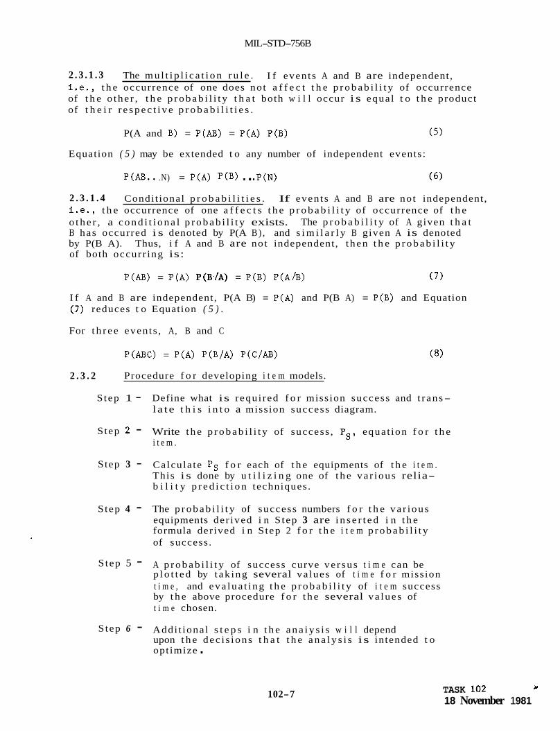
2 . 3 . 1 . 3 i .e., t h e occurrence of one does not a f f e c t t h e p r o b a b i l i t y of occurrence of t h e o the r , t h e p r o b a b i l i t y t h a t both w i l l occur i s equal t o t h e product of t h e i r r e s p e c t i v e p r o b a b i l i t i e s .
The m u l t i p l i c a t i o n r u l e . I f events A and B are independent,
P(A and B) = P(AB) = P(A) P(B) ( 5 )
Equation ( 5 ) may be extended t o any number of independent events:
P(AB.. .N) = P(A) P(B) . . .P(N) ( 6 )
2 . 3 . 1 . 4 i .e . , t h e occurrence of one a f f e c t s t h e p r o b a b i l i t y of occurrence of t h e o t h e r , a c o n d i t i o n a l p r o b a b i l i t y exists. B has occurred i s denoted by P(A B ) , and s i m i l a r l y B given A is denoted by P(B A). Thus, i f A and B are not independent, t hen t h e p r o b a b i l i t y of both occurr ing is:
Condit ional p r o b a b i l i t i e s . If events A and B are not independent,
The p r o b a b i l i t y of A given t h a t
P(AB) = P(A) P(B,/A) = P(B) P(A/B) ( 7 )
I f A and B are independent, P(A B) = P(A) and P(B A) = P(B) and Equation ( 7 ) reduces t o Equation ( 5 ) .
For t h r e e events , A, B and C
P(ABC) = P(A) P(B/A) P(C/AB) (8)
2 . 3 . 2 Procedure f o r developing i t e m models.
S tep 1 - Define what is requi red f o r mission success and t r ans- la te t h i s i n t o a mission success diagram.
S tep 2 - Write t h e p r o b a b i l i t y of success , Ps, equat ion f o r t h e i t e m .
Step 3 - Calcula te Ps f o r each of t h e equipments of t h e i t e m . This i s done by u t i l i z i n g one of t h e va r ious relia- b i l i t y p r e d i c t i o n techniques.
S tep 4 - The p r o b a b i l i t y of success numbers f o r t h e va r ious equipments der ived i n S tep 3 are i n s e r t e d i n t h e formula derived i n S tep 2 f o r t h e i t e m p r o b a b i l i t y of success .
S tep 5 - A p r o b a b i l i t y of success curve ve r sus t i m e can be p l o t t e d by t ak ing several va lues of t i m e f o r mission t i m e , and eva lua t ing t h e p r o b a b i l i t y of i t e m success by t h e above procedure f o r t h e several va lues of t i m e chosen.
S tep 6 - Addi t iona l s t e p s i n t h e a n a i y s i s w i l l depend upon t h e dec i s ions t h a t t h e a n a l y s i s is intended t o opt imize .
102-7 Y TASK 102
18 November 1 981

MIL-STD-756B
2.4 Discussion of procedure. A s descr ibed i n 1 .2 of Task 102 i t i s necessary t o d e f i n e t h e s p e c i f i c mission of i n t e r e s t ( i f more than one exists), t h e phases of opera t ion , t h e func t ions and a l t e r n a t e modes of ope ra t ion t o perform these func t ions .
Defining mission success is tantamount t o w r i t i n g a word s tatement which d e s c r i b e s what equipments o r combinations of equipments are requi red f o r mission success and drawing a r e l i a b i l i t y block diagram f o r t h e s tatement . Seve ra l methods of going from a r e l i a b i l i t y block diagram t o a p r o b a b i l i t y of s u r v i v a l formula are shown i n t h i s s ec t ion .
For example, a word s tatement might be:
Equipments A, B , and C , o r D and E , and equipment F must work f o r mission success . The Mission R e l i a b i l i t y block diagram would be as fo l lows:
SUCCESS
It i s no t convenient t o go d i r e c t l y from t h i s Mission R e l i a b i l i t y diagram t o a p r o b a b i l i t y of success equat ion f o r t h e system. of s u r v i v a l equat ion is:
The c o r r e c t p r o b a b i l i t y
- ps - PAPBPCPF + PDPEPF - PAPBPCPDPEPF
A t f i r s t i t might appear t h a t t h e p r o b a b i l i t y of success equat ion could be w r i t t e n as
where PA = p r o b a b i l i t y of equipment A working.
The event t h a t A , B , C , and F works ( represented by ABCF) and t h a t t h e event D, E , and F works ( represented by DEF) are not mutually exc lus ive . Consequently, adding t h e p r o b a b i l i t i e s of t h e s e two even t s , PAPBPcPF +- PDPEPF does not y i e l d t h e c o r r e c t r e s u l t .
Another word s tatement could be t h a t any two of t h r e e genera tors A , B , and C must work f o r success . I n o t h e r words, t h e genera tors are phys i ca l ly ope ra t ing i n p a r a l l e l and any two have t h e c a p a b i l i t y t o supply t h e needs of t h e system. Its mission success diagram may be shown i n one of two ways:
I
102-8 TASK 102 18 November 1981
- -__ . -- - - - _ _ " _I____ --

MIL-STD-756B
or
The "(2/3)" of diagram (a) denotes that two of the three equipments must operate for success. success criteria of parallel equipments. Diagram (b) is the equivalent of diagram (a) but becomes a cumbersome technique when expanded beyond three parallel equipments.
Diagram (a) is the easiest technique to model
3. REQUIREMENT
3.1 The contractor shall develop and maintain a Mission Reliability model for each configured item required to perform the mission functions. A Mission Reliability block diagram shall be developed and maintained for the item with associated allocations and predictions in each reliabilty block. to the Basic Reliability model, functional block diagram, schematics and drawings, and shall provide the basis for accurate mathematical representation of Mission Reliability. the Mission Reliability diagrams shall be consistent with that used in the Basic Reliability model, functional block diagram, drawings and schematics, weight statements, power budgets and specifications.
The Mission Reliability block diagram shall be keyed and traceable
Nomenclature of elements of the item used in
3.2 Hardware or functional elements of the item which are not included in the Mission Reliability model shall be identified. Rationale for each element's exclusion from the Mission Reliability model shall be provided.
3.3 being readily updated with information resulting from reliability and other relevant tests as well as changes in item configuration, mission parameters and operational constraints.
The Mission Reliability mathematical model shall be capable of
3.4 If a Failure Mode, Effects and Criticality Analysis (FMECA) is required, the Mission Reliability model and the FMECA shall be consistent in the definition of mission success and utilization of elements of the item in redundant and alternate modes of operation in specific mission phases.
102-9 TASK 102 18 November 1981


MIL-S TD- 75 6 B
TASK SECTION 200
RELIABILITY PREDICTION
1. DOCUMENTS REFERENCED I N TASK SECTION 200:
STANDARDS
M i l i t a r y
MIL-STD-1670 Environmental Criteria and Guidel ines f o r A i r - Launched Weapons
HANDBOOKS
M i l i t a r y
MIL-HDBK-217 R e l i a b i l i t y P r e d i c t i o n of E lec t ron ic Equipment
MIL-HDBK-251 Re l i ab i l i t y /Des ign Thermal Applicat ions
OTHER PUBLICATIONS
RADC-TR-73-248 Dormancy and Power On-Off Cycling E f f e c t s on E lec t ron ic Equipment and P a r t R e l i a b i l i t y
RADC-TR- 7 4- 2 6 9 E f f e c t s of Dormancy on Nonelectronic Components and Materials
LC- 7 8-1 Storage R e l i a b i l i t y of Missile Material Program, Missile Material R e l i a b i l i t y Handbook P a r t Count P r e d i c t i o n
GIDEP Government Indus t ry Data Exchange Program, Summaries of F a i l u r e Rates
NPRD-1 Nonelectronic P a r t s R e l i a b i l i t y Data, 1978
2. GENERAL REQUIREMENTS
2 . 1 C l a s s i f i c a t i o n . R e l i a b i l i t y p r e d i c t i o n s , as defined he re in , are c l a s s i f i e d as fol lows:
Type I - F e a s i b i l i t y p r e d i c t i o n
Type I1 - Prel iminary design p red ic t ion
Type I11 - Detai led des ign p r e d i c t i o n
200-1 TASK SECTION 200 18 November 1981
MIL-STD-756B
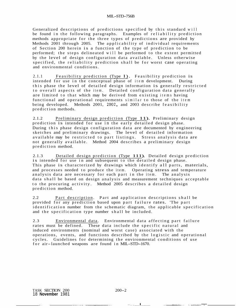
Generalized d e s c r i p t i o n s of p r e d i c t i o n s s p e c i f i e d by t h i s s tandard w i l l be found i n t h e fol lowing paragraphs. Examples of r e l i a b i l i t y p r e d i c t i o n methods appropr i a t e f o r t h e t h r e e types of p r e d i c t i o n s are provided by Methods 2001 through 2005. The a p p l i c a b i l i t y of i n d i v i d u a l requirements of Sec t ion 200 he re in i s a func t ion of t h e type of p r e d i c t i o n t o be performed; t h e s t e p s de l inea ted w i l l be performed t o t h e ex t en t permit ted by t h e level of des ign conf igura t ion d a t a a v a i l a b l e . Unless o therwise s p e c i f i e d , t h e r e l i a b i l i t y p r e d i c t i o n s h a l l be f o r worst case ope ra t ing and environmental condi t ions .
2 .1 .1 F e a s i b i l i t y p r e d i c t i o n (Type I) . F e a s i b i l i t y p r e d i c t i o n is intended f o r use i n t h e conceptual phase of i t e m development. During t h i s phase t h e level of d e t a i l e d des ign information i s gene ra l ly r e s t r i c t e d t o o v e r a l l a s p e c t s of t h e i t e m . Detai led conf igu ra t ion d a t a gene ra l ly are l imi t ed t o t h a t which may be der ived from e x i s t i n g i t e m s having func t iona l and ope ra t iona l requirements s i m i l a r t o those of t h e i t e m being developed. Methods 2001, 2002, and 2003 desc r ibe f e a s i b i l i t y p r e d i c t i on methods.
2.1.2 Pre l iminary design p r e d i c t i o n (Type 11). Prel iminary design p r e d i c t i o n i s intended f o r use i n t h e e a r l y d e t a i l e d des ign phase. During t h i s phase des ign conf igu ra t ion d a t a are documented by engineering ske tches and pre l iminary drawings. The level of d e t a i l e d information a v a i l a b l e may be r e s t r i c t e d t o p a r t l i s t i n g s . S t r e s s a n a l y s i s d a t a are not gene ra l ly a v a i l a b l e . Method 2004 desc r ibes a pre l iminary des ign p r e d i c t i o n method.
2.1.3 Detai led des ign p r e d i c t i o n (Type 111). Detai led des ign p r e d i c t i o n i s intended f o r use i n and subsequent t o t h e d e t a i l e d des ign phase. -~ This phase is cha rac t e r i zed by drawings which i d e n t i f y a l l p a r t s , materials, and processes needed t o produce t h e i t e m . Operating stress and temperature a n a l y s i s d a t a are necessary f o r each p a r t i n t h e i t e m . The a n a l y s i s d a t a s h a l l be based on design a n a l y s i s and measurement techniques accep tab le t o t h e procuring a c t i v i t y . Method 2005 desc r ibes a d e t a i l e d design p r e d i c t i o n method.
2.2 P a r t d e s c r i p t i o n . P a r t and a p p l i c a t i o n d e s c r i p t i o n s s h a l l be provided f o r any p r e d i c t i o n based upon p a r t f a i l u r e rates. 'The p a r t i d e n t i f i c a t i o n number from t h e schematic diagram, t h e app l i cab le s p e c i f i c a t i o n and t h e s p e c i f i c a t i o n type number s h a l l be included.
2.3 Environmental da ta . Environmental d a t a a f f e c t i n g p a r t f a i l u r e rates must be defined. These d a t a i nc lude t h e s p e c i f i c n a t u r a l and induced environments (nominal and worst ca se ) a s soc i a t ed wi th t h e opera t ions , events , and func t ions descr ibed by t h e l o g i s t i c and ope ra t iona l cyc les . Guidel ines f o r determining t h e environmental cond i t i ons of use f o r air- launched weapons are found i n MIL-STD-1670.
TASK SECTION 200 200-2 18 November 1981
.. I _I___ --..__I_____ _--_ -I-_-_Ix .-.-
MIL-STD-756B
2.3 .1 Environmental ca t egor i e s . Environmental c a t e g o r i e s s h a l l be def ined f o r each service use event using Table 700-Las a guide of t y p i c a l ca t egor i e s . Data sources, such as MIL-HDBK-217 and WRD-1 which u t i l i z e environmental f a c t o r s t o a d j u s t f a i l u r e rates, s h a l l apply t h e environmental f a c t o r which most c l o s e l y matches t h e intended environment. Fac to r s u t i l i z e d s h a l l be c i t e d and s u b s t a n t i a t e d .
2.3.2 P a r t ope ra t ing temperature. P a r t temperatures used f o r p r e d i c t i o n purposes s h a l l inc lude t h e i t e m i n t e r n a l temperature rise as determined by thermal a n a l y s i s o r test da t a . thermal a n a l y s i s procedures, r e f e r t o MIL-HDBK-251.
For gene ra l guidance and d e t a i l e d
2.4 S t r e s s ana lys i s . Analyses s h a l l be performed t o determine t h e ope ra t ing stresses t o be experienced by each p a r t commensurate wi th t h e p r e d i c t i o n c l a s s i f i c a t i o n and t h e des ign d e t a i l a v a i l a b l e . These ana lyses s h a l l be based on techniques acceptab le t o t h e procuring a c t i v i t y . F a i l u r e rates s h a l l be modified by appropr i a t e f a c t o r s t o account f o r t h e e f f e c t of appl ied stress. S t r e s s r a t i o s c i t e d i n t h e p r e d i c t i o n r e p o r t s h a l l be i n d i v i d u a l l y i d e n t i f i e d as Estimated (E) , Calculated (C) , o r Measured (M) . 2.5 F a i l u r e d i s t r i b u t i o n s . The f a i l u r e d i s t r i b u t i o n appropr i a t e t o t h e s p e c i f i c e l e c t r o n i c , e lectr ical , e lectromechanical , mechanical, and ordnance i t e m s h a l l be used i n computation. I n i n s t ances where t h e f a i l u r e d i s t r i b u t i o n f o r t he item i s not known, t h e exponent ia l , binominal, weibul l , o r o the r f a i l u r e d i s t r i b u t i o n may be assumed. The f a i l u r e d i s t r i b u t i o n s u t i l i z e d s h a l l be c i t e d and any assumptions subs t an t i a t ed in t h e p r e d i c t i o n r epor t .
2.6 F a i l u r e rates. Fa i lu re rates f o r a l l e l e c t r o n i c , e lectr ical , e lectromechanical , mechanical, and ordnance items are requi red f o r each s i g n i f i c a n t event and environment def ined by t h e service use p r o f i l e . All sources of f a i l u r e d a t a s h a l l be approved by t h e procuring a c t i v i t y p r i o r t o use. Basic f a i l u r e rates from most d a t a sources must be modified w i t h app ropr i a t e f a c t o r s t o account f o r t h e s p e c i f i c i t e m a p p l i c a t i o n under cons idera t ion . Fac to r s used s h a l l be c i t e d and s u b s t a n t i a t e d i n t h e p r e d i c t i o n r epor t .
2.6.1 Funct iona l group f a i l u r e rates . Funct ional group f a i l u r e rates may be derived from f a i l u r e rate d a t a f o r f u n c t i o n a l l y s i m i l a r groups o r i t e m s . The GIDEP F a i l u r e R a t e Summaries are an a v a i l a b l e source f o r l o c a t i n g group and i t e m f a i l u r e rates.
2.6.2 Operating f a i l u r e rates. Operating f a i l u r e rates f o r e l e c t r o n i c and electromechanical p a r t s may be found i n MIL-HDBK-217. F a i l u r e rates f o r o the r p a r t s may be found i n NPRD-1, t h e GIDEP F a i l u r e R a t e Summaries, and o t h e r sources.
200-3 TASK SECTION 200 18 November 1981

MIL-STD-756B
2.6.3 Nonoperating f a i l u r e rates. Nonoperating f a i l u r e rates f o r p a r t s t a k e i n t o cons ide ra t ion p e r t i n e n t environmental i n f luences o r o t h e r stresses of t h e app l i ca t ion . RADC-TR-74-269, and LC-78-1 provide nonoperating f a i l u r e rates.
Data sources such as RADC-TR-73-248,
2.6.4 found i n d a t a sources such as WC-TR-73-248, WC-TR-74-269, and LC-
S torage f a i l u r e rates. S torage f a i l u r e rates f o r p a r t s may be
78-1.
2.7 Item r e l i a b i l i t y . I t e m r e l i a b i l i t y s h a l l be computed us ing mathematical models and app l i cab le f a i l u r e rate da t a . The p r e d i c t i o n r e s u l t s s h a l l be expressed i n t e r m s c o n s i s t e n t w i th t h e s p e c i f i e d r e l i a b i l i t y requirements.
3. DETAILS TO BE SPECIFIED BY THE PA (SEE 5.1.1). The fol lowing are app l i cab le when Tasks 201 o r 202 are involved:
a.
(R) b*
C.
d.
e.
f .
g *
h.
(R) i.
Since r e l i a b i l i t y modeling t a s k s are normally p r e r e q u i s i t e t a s k s t o p r e d i c t i o n t a sks , elements i n 3 of Task Sec t ion 100 apply.
P r e d i c t i o n Type (See 2.1 of Task Sec t ion 200).
Worst Case A p p l i c a b i l i t y (See 2.1 of Task Sec t ion 200).
Environmental Categories (See 2.3.1 of Task Sec t ion 200).
S t r e s s Analysis A p p l i c a b i l i t y (See 2.4 of Task Sec t ion 200).
F a i l u r e R a t e Data Sources (See 2.6 of Task Sec t ion 200).
I t e m R e l i a b i l i t y Requirements (See 2.7 of Task Sec t ion 200).
DI-R-7095 ( R e l i a b i l i t y P r e d i c t i o n and Documentation of Supporting Data) should be s p e c i f i e d when d e l i v e r a b l e d a t a i s des i r ed i n conjunct ion wi th t h i s t a sk .
P r e d i c t i o n Method(s). An op t ion i s t o al low con t r ac to r s e l e c t i o n of t h e app ropr i a t e p r e d i c t i o n method(s). methods may be app l i cab le t o d i f f e r e n t system components.
D i f f e ren t p r e d i c t i o n
TASK SEC I O N 2 18 Novem t er 19 !4! 200-4

MIL-STD-756B
Table 200-1. Environmental Symbol Identification and Description.
Ground, Benign
Space, Flight
Ground, Fixed
Ground, Mobile
Naval, Sheltered
Naval, Unsheltered
Airborne, Inhabited, Transport
Airborne, Inhabited, Fighter
Airborne, Inhabited, Helicopter
Airborne, Uninhabited, Transport
Airborne, Uninhabited, Fighter
Airborne, Uninhabited. Helicopter
Missile, Launch
Missile, Captive Carry
Missile, Free Flight
Symbol
GB
SF
GF
GM
NS
NU
AIT
AIF
AIH
%T
%F
%H
Y,
MC
MF
Nominal Environmental Conditions
Nearly zero environmental stress.
Earth orbital. Approaches Ground, Benign conditions. Vehicle neither under powered flight nor in atmos- pheric reentry.
Conditions less than ideal to include installation in permanent racks with adequate cooling air and possible installation in unheated buildings.
Conditions more severe than those h r GF, mostly for vibration and shock. Cooling air supply may also be more limited.
Surface ship conditions similar to GF but subject to occasional high shock and vibration.
Nominal surface shipborne conditions but with repetitive high levels of shock and vibration.
Typical conditions in transport or bomber compartments occupied by aircrew without environmental extremes of pressure, temperature, shock and vibration, and installed on long mission aircraft such as transports and bombers.
Same as AIT but installed on high performance aircraft such as fighters and interceptors.
Same as AI as helicopTers.
but installed on rotary wing aircraft such
Bomb bay, equipment bay, tail, or wing installations where extreme pressure, vibration and temperature cycling may be aggravated by contamination from oil, hydraulic fluid and engine exhaust. mission aircraft such as transports and bombers.
Same as A but installed on high performance aircraft such as fyihters and interceptors.
Installed on long
installed on rotary wing aircraft such
Severe conditions of noise, vibration, and other environments related to missile launch, and space vehicle boost into orbit, vehicle re-entry and landing by parachute. tion near main rocket engines during launch operations.
Same as A,, , % aircraft pTatfoFm.
Typical conditions of pressure, vibration and tempera- ture experienced in atmospheric flight to target.
Conditions may also apply to installa-
or AVH depending on the applicable
200-5 TASK SECTION 200 18 November 1981


MIL-STD-756B
TASK 201
BASIC RELIABILITY PREDICTION
1 . PURP 0 SE / RAT IONALE
1.1 estimating the demand for maintenance and logistic support caused by an item and its component parts.
A Basic Reliability prediction utilizes a series model for
1.2 Mission Reliability prediction. Whereas the Mission Reliability prediction indicates the capability of the item design to successfully accomplish mission objectives, the Basic Reliability prediction indicates the degree of maintenance and logistic support burden to be anticipated due to item unreliability. It would be expected that for alternative item design configurations with equivalent mission reliability and technical development risk, the item design configuration with the higher support reliability is the preferred design for enhancing operational readiness and minimizing the costs associated with maintenance and logistics support. In certain instances, a design configuration with less mission reliability than other design configurations may be preferred if the design's Basic reliability is significantly better than the competing design.
The Basic Reliability prediction is used in conjunction with a
1 . 3 possible and updated whenever changes in design or data occur. early predictions are inherently unrefined because of insufficient design detail, they provide useful feedback to designers and management in either establishing reliability requirements in the form of apportionments (allocations) or the feasibility of meeting reliability requirements.
A Basic Reliability prediction should be prepared as soon as While
1.4 A s the item progresses from paper design to hardware stages, predictions evolve into assessments as actual program test data become available and are integrated into the calculations. bnth predictions and assessments i s a function of data quality and asswptions. yalid, timely aqalyses projecting or indicating deficient reliability attainment grovide the basis for corrective action, and the sooner that corrective action is identtfied, the less its implementation is impacted by program constraints, and the higher are the payoffs over the life of the item.
The validity of
1.5 The prediction and assessment tasks, iterative and interrelated with activities such as reliability allocation and configuration analyses, should be specified by the procuring activity during the early acquisition phases to determine reliability feasibility and, during the development production phases, to determine reliability acceptability.
2. REQUIREMENT
2 . 1 The contractor shall prepare, and maintain a Basic Reliability prediction based upon a defined configuration and an associated Basic Reliability model. All equipments and associated quantities comprising
201-1 TASK 201 18 November 7 981
M I L-STD- 7 5 6B
t h e i t e m s h a l l be included i n t h e model except f o r documented exclusions approved by the procuring a c t i v i t y . F a i l u r e rate d a t a (or equivalent r e l i a b i l i t y parameters) s h a l l be cons i s t en t with t h e level of d e t a i l of t h e Basic R e l i a b i l i t y model and a v a i l a b i l i t y of procuring a c t i v i t y approved re levant da ta sources f o r a comprehensive p red ic t ion (e.g., software r e l i a b i l i t y , human r e l i a b i l i t y , s to rage r e l i a b i l i t y , e t c . ) .
2.2 When required, p red ic t ions s h a l l account f o r , and d i f f e r e n t i a t e between, each mode of i t e m opera t ion as defined i n t h e i t e m s p e c i f i c a t i o n . P red ic t ions s h a l l be made showing t h e c a p a b i l i t y of t h e i t e m t o m e e t a l l r e l i a b i l i t y requirements spec i f i ed by t h e procuring a c t i v i t y . The p red ic t ion shall be based upon t h e worst-case s e r v i c e use p o r f i l e unless otherwise speci f ied .
2 . 3 A l l da t a sources f o r f a i l u r e rates, f a i l u r e d i s t r i b u t i o n and f a i l u r e rate adjustment fac tors (e .g . , stress f a c t o r s , duty cycle , e t c . ) s h a l l be i d e n t i f i e d f o r each r e l i a b i l i t y block. Data sources s h a l l be as spec i f i ed o r otherwise approved by t h e procuring a c t i v i t y .
TASK 201 18 November 1981 201-2

MIL-STD-756B
TASK 202
MISSION RELIABILITY PmDICTION
1. PURPOSE/RATIONALE
1.1 s e r i e s- p a r a l l e l model f o r est imating an item's c a p a b i l i t y t o successfu l ly perform spec i f i ed mission objec t ives .
A Mission R e l i a b i l i t y p red ic t ion normally u t i l i z e s a complex
1 . 2 a Support R e l i a b i l i t y predic t ion . p red ic t ion i n d i c a t e s t h e c a p a b i l i t y of the i t e m design t o successfu l ly accomplish mission ob jec t ives , t he Support R e l i a b i l i t y p red ic t ion i n d i c a t e s t h e degree of maintenance and l o g i s t i c support burden t o be an t i c ipa ted due t o i t e m u n r e l i a b i l i t y . Obviously, f o r a l t e r n a t i v e i t e m design conf igura t ions with equivalent mission r e l i a b i l i t y and t echn ica l development r i s k , t h e i t e m des ign conf igura t ions with t h e higher support r e l i a b i l i t y i s t h e prefer red design f o r enhancing ope ra t iona l readiness and minimizing t h e c o s t s associa ted wi th maintenance and l o g i s t i c s support . I n c e r t a i n ins tances , a design conf igura t ion with less mission r e l i a b i l i t y than o t h e r design conf igura t ions may be prefer red i f t h e design 's support r e l i a b i l i t y i s s i g n i f i c a n t l y b e t t e r than t h e competing design.
The Mission R e l i a b i l i t y p red ic t ion is used i n conjunct ion wi th Whereas t h e Mission R e l i a b i l i t y
1.3 poss ib le and updated whenever changes i n design o r da ta occur. early p red ic t ions are inhe ren t ly unrefined because of i n s u f f i c i e n t design d e t a i l , they provide u s e f u l feedback t o des igners and management An e i t h e r e s t ab l i sh ing r e l i a b i l i t y requirements i n t h e form of apportionments (allocatiQns) o r t h e f e a s i b i l i t y of meeting r e l i a b i l i t y requirements.
1.4 As t h e item progresses from paper des ign t o hardware s t ages , p red ic t ions evolve i n t o assessments as a c t u a l program test da ta become ava i l ab le gqd are in teg ra ted i n t o t h e ca lcu la t ions . boqh pxediscions and assessments is a funct ion of d a t a q u a l i t y and gs.qun)ptioqs, valid, timely analyses p ro jec t ing o r i nd ica t ing d e f i c i e n t xeli ,abil , i ty atqainment provide the bqsis f o r c o r r e c t i v e acqion, and the sooner t h a t c o r r e c t i v e a c t i o n i s i d e n t i f i e d , t h e less i ts implementation i s impacted by program cons t ra in t s , and t h e higher a r e . t h e payoffs over t h e l i f e of t h e i t e m .
A Mission R e l i a b i l i t y p red ic t ion should be prepared as soon as While
The v a l i d i t y of
1.5 The p red ic t ion and assessment t a sks , i terat ive and i n t e r r e l a t e d wi th a c t i v i t i e s such as r e l i a b i l i t y a l l o c a t i o n and conf igura t ion analyses , should be spec i f i ed by the procuring a c t i v i t y during t h e e a r l y a c q u i s i t i o n phases t o determine r e l i a b i l i t y f e a s i b i l i t y and, during t h e development and production phases, t o determine r e l i a b i l i t y accep tab i l i ty .
202-1 TASK 202 . 18 November '1 981

MIL-STD-756B
2. REQUIREMENT
2 . 1 p r e d i c t i o n based upon a defined conf igu ra t ion and an a s soc i a t ed Mission R e l i a b i l i t y model. A l l equipments and a s soc i a t ed q u a n t i t i e s comprising t h e i t e m s h a l l be included i n t h e model except f o r documented exc lus ions approved by t h e procuring a c t i v i t y . The p r e d i c t i o n s h a l l r e f l e c t des ign p rov i s ions f o r i t e m redundancies and a l t e r n a t e modes of ope ra t ion intended t o enhance mission success . F a i l u r e rate d a t a (or equiva len t r e l i a b i l i t y parameters) s h a l l be c o n s i s t e n t wi th t h e level of d e t a i l of t h e Mission R e l i a b i l i t y model and a v a i l a b i l i t y of procuring a c t i v i t y approved r e l e v a n t d a t a sources f o r a comprehensive p r e d i c t i o n (e.g., sof tware r e l i a b i l i t y , human r e l i a b i l i t y , s to rage r e l i a b i l i t y , e t c . ) .
The con t r ac to r s h a l l p repare and maintain a Mission R e l i a b i l i t y
2.2 When requi red , p r e d i c t i o n s s h a l l account f o r , and d i f f e r e n t i a t e between, each mode of i t e m ope ra t ion as defined i n t h e i t e m s p e c i f i c a t i o n . P red ic t ions s h a l l be made showing t h e c a p a b i l i t y of t h e i t e m t o m e e t a l l r e l i a b i l i t y requirements s p e c i f i e d by t h e procuring a c t i v i t y . The p r e d i c t i o n s h a l l be based upon t h e worst case service use p r o f i l e un le s s otherwise spec i f i ed .
2 .3 A l l d a t a sources f o r f a i l u r e rates, f a i l u r e d i s t r i b u t i o n s and f a i l u r e rate adjustment f a c t o r s (e.g. , stress f a c t o r s , duty cyc l e , etc.) s h a l l be i d e n t i f i e d f o r each r e l i a b i l i t y block. as s p e c i f i e d o r otherwise approved by t h e procuring a c t i v i t y .
Data sources s h a l l be
TASK 202 18 November 1 981 202-2

MIL-STD-756B
METHOD 1001
CONVENTIONAL PROBABILITY
1. PURPOSE. The purpose of t h e convent ional p r o b a b i l i t y method i s t o prepare a r e l i a b i l i t y mathematical model from a r e l i a b i l i t y block diagram by means of convent ional p r o b a b i l i t y r e l a t i o n s h i p s . p r o b a b i l i t y method is app l i cab le t o s i n g l e funct ioned and mul t i func t ioned sy s t e m s .
The conventional
2. PROCEDURE.
2 . 1 S ing le funct ioned systems. S ing le funct ioned systems c o n s i s t of equipments considered t o have a s i n g l e func t ion a s soc i a t ed wi th equipment performance. diagram can take t h e form of equipments connected i n series, p a r a l l e l , s e r i e s- p a r a l l e l , o r a complex conf igura t ion . A l t e rna t e modes of ope ra t ion can be considered i n s i n g l e funct ioned system models. system Basic R e l i a b i l i t y diagram can only be a series conf igu ra t ion i n which any equipments provided f o r redundancy o r a l t e r n a t e modes of ope ra t ion f o r mission success are modeled i n series. The convent ional p r o b a b i l i t y method makes use of t h e equat ions developed f o r redundancy t o handle series, p a r a l l e l , and s e r i e s- p a r a l l e l combinations of equipments. For non- series para l le l o r complex conf igu ra t ions , use o r repeated use of t h e fol lowing equat ion is required.
The s i n g l e funct ioned system Mission R e l i a b i l i t y
The s i n g l e funct ioned
Ps = Ps ( i f X i s good) % + Ps ( i f X is bad) Qx (1)
Where Ps = r e l i a b i l i t y of mission
Ps ( i f X i s good) = r e l i a b i l i t y of mission i f X is good
Ps ( i f X i s bad) = r e l i a b i l i t y of mission i f X is bad
% = r e l i a b i l i t y of X
% Qx = u n r e l i a b i l i t y of 3 = 1 -
In QtheF words, t h e r e l i a b i l i t y of t h e mission i s equal t o t h e r e l i a b i l i t y of t h e mission given a s p e c i f i c p o r t i o n of t h e system works t imes t h e p r o b a b i l i t y t h a t a po r t ion of t h e system w i l l work p l u s t h e r e l i a b i l i t y of t h e mission given t h a t a s p e c i f i c p o r t i o n of t h e system f a i l s t i m e s t h e p r o b a b i l i t y t h a t t h a t po r t ion f a i l s .
The aboye formula can a lso be used t o genera te p r o b a b i l i t y of success equat ions f o r s e r i e s- p a r a l l e l conf igura t ions .
Formulas f o r p r o b a b i l i t y of success , Ps, f o r va r ious system conf igura t ions are derived as fol lows f o r ya r ious success diagrams. Each formula shown can be used as a bu i ld ing block t o eya lua t e a more complex success diagram.
1001-1 METHOD 1001 18 November 1981
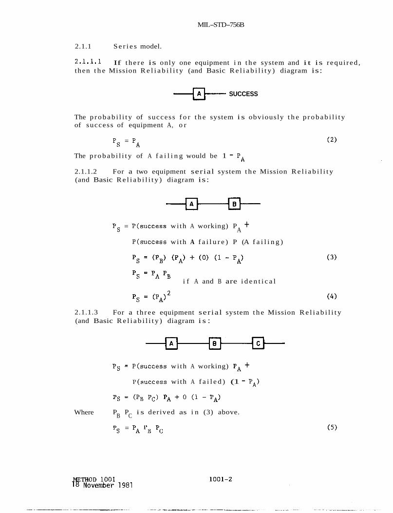
MIL-STD-756B
2.1.1 S e r i e s model.
2 .1 .1 .1 then t h e Mission R e l i a b i l i t y (and Basic R e l i a b i l i t y ) diagram is:
If t h e r e is only one equipment i n t h e system and i t is r equ i r ed ,
-m-~ SUCCESS
The p r o b a b i l i t y of success f o r t h e system i s obviously t h e p r o b a b i l i t y of success of equipment A, o r
Ps = PA (2)
The p r o b a b i l i t y of A f a i l i n g would be 1 - PA
2.1.1.2 For a two equipment serial system t h e Mission R e l i a b i l i t y (and Basic R e l i a b i l i t y ) diagram is:
Ps = P(success wi th A working) P + P(success wi th A f a i l u r e ) P (A f a i l i n g )
A
i f A and B are i d e n t i c a l 'S = 'A 'B
2.1.1.3 (and Basic R e l i a b i l i t y ) diagram i s :
For a t h r e e equipment ser ia l system t h e Mission R e l i a b i l i t y
PCJ = P(success wi th A working) PA + P(success with A f a i l e d ) (1 - PA)
Ps = (PB PC) PA + 0 (1 - PA)
P P i s derived as i n (3) above. B C Where
Ps = PA PB Pc (5)
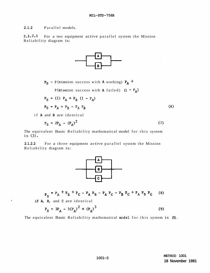
MIL-STD-756B
2.1.2 P a r a l l e l models.
2.1.2.1 For a two equipment active p a r a l l e l system t h e Mission R e l i a b i l i t y diagram is:
Ps = P(mission success w i t h A working) PA + P(mission success wi th A f a i l e d ) (1 - PA)
i f A and B are i d e n t i c a l
The equiva len t Basic R e l i a b i l i t y mathematical model f o r t h i s system i s ( 3 ) .
2.1.2.2 For a t h r e e equipment active p a r a l l e l system t h e Mission R e l i a b i l i t y diagram is:
pS PA + pB + Pc - PA Pg - PA Pc - Pg Pc + PA PB Pc ( 8 )
if A, B, and C are i d e n t i c a l
The equiva len t Basic R e l i a b i l i t y mathematical model f o r t h i s system is (5).
1001-3 METHOD 1001 18 November 1981

MIL-STD-756B
2.1.2.3 diagram is:
For a two equipment standby p a r a l l e l system t h e Mission R e l i a b i l i t y
I
The switch, S , d e t e c t s a f a i l u r e of t h e o p e r a t i v e element and ins tan taneous ly swi tches from t h e f a i l e d element t o a standby element.
The switch may f a i l i n two ways: requi red , Q and (2) t h e switch may ope ra t e without command ( i . e . , prematurely!, Q2.
(1) t h e switch may f a i l t o ope ra t e when
Ps =
- ps - Ps =
Where P1 =
P2 =
The equiva len t
Ps =
2.1.2.4
P(mission success wi th A working) PA + P(mission success wi th A f a i l e d ) (1 - PA)
p r o b a b i l i t y of no f a i l u r e t o swi tch when requi red
p r o b a b i l i t y of no premature switching.
Basic R e l i a b i l i t y mathematical model f o r t h i s system is:
'A 'B '1 '2
For a t h r e e element ma jo r i t y vo t ing redundancy t h e Mission R e l i a b i l i t y diagram is:
METHOD 1001 18 November 1981
1001-4
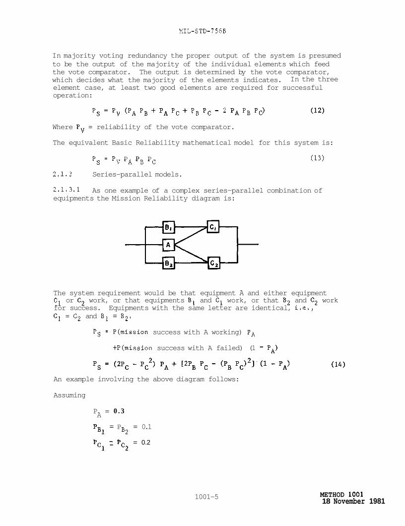
MIL-STD-756B
In majority voting redundancy the proper output of the system is presumed to be the output of the majority of the individual elements which feed the vote comparator. The output is determined by the vote comparator, which decides what the majority of the elements indicates. element case, at least two good elements are required for successful operation:
In the three
Ps = Pv (PA PB + PA PC + PB PC - 2 PA PB Pc) (12)
Where Pv = reliability of the vote comparator.
The equivalent Basic Reliability mathematical model for this system is:
P s = P P P P (13) V A B C
2.1.3 Series-parallel models.
2.1.3.1 equipments the Mission Reliability diagram is:
As one example of a complex series-parallel combination of
The system requirement would be that equipment A and either equipment C1 or C2 work, or that equipments B1 and C1 work, or that B2 and C2 work for success. Equipments with the same letter are identical, i.e., C1 = C2 and B1 = B2.
Ps = P(mission success with A working) PA
+P(mission success with A failed) (1 - PA)
An example involving the above diagram follows:
Assuming
P = 0 . 3 A = P = 0.1
pB1 B2 = 0.2 -
pcl - pc2
1001-5 METHOD 1001 18 November 1981

MIL-STD- 7 5 6B
-
and theref ore,
'D
-
(1 - PA) = 0.7
(1 - PB) = 0.9
( 1 - Pc) = 0.8
Evaluating t h e p robab i l i ty of success f o r a given mission as:
Ps = ( - 4 - . 0 4 ) . 3 + C.04 - .0004] ( - 7 )
Ps = 0.13572
The equivalent Basic R e l i a b i l i t y mathematical model f o r t h i s system is:
(1 57 2 2 pC Ps = PA PB
and the Basic R e l i a b i l i t y is 0.00012.
2.1.3.2 R e l i a b i l i t y diagram. increas ingly complex i t could be broken down i n t o p a r t s as shown i n the diagram below.
The same procedure can be followed f o r any complex Mission A s the Mission R e l i a b i l i t y diagram becomes
Equipments with the same le t ter are i d e n t i c a l .
I I
Reducing the mission success diagram using (14) and (7)
METHOD 1001 18 November 1981
1001-6
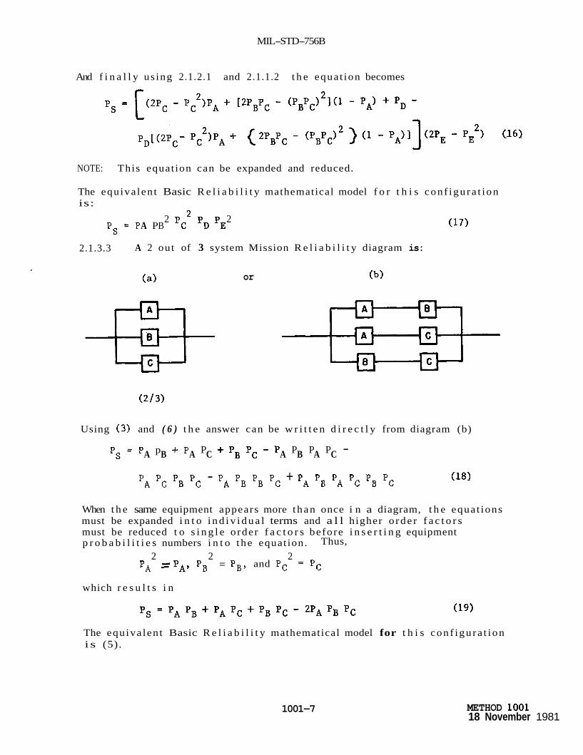
MIL-STD-756B
And f i n a l l y us ing 2.1.2.1 and 2.1.1.2 t h e equat ion becomes
NOTE: This equat ion can be expanded and reduced.
The equiva len t Basic R e l i a b i l i t y mathematical model f o r t h i s con f igu ra t ion is:
2 2 P s = P A P B pt 'D 'E
2.1.3.3 A 2 out of 3 system Mission R e l i a b i l i t y diagram is:
or
Using (3) and ( 6 ) t h e answer can be w r i t t e n d i r e c t l y from diagram (b)
P s = P p + P P + P g P c - P P P P - A B A C A B A C
PA Pc PB Pc - PA PB PB Pc + PA PB PA Pc PB Pc (18)
When t h e same equipment appears more than once i n a diagram, t h e equat ions must be expanded i n t o i n d i v i d u a l terms and a l l higher o rde r f a c t o r s must be reduced t o s i n g l e order f a c t o r s before i n s e r t i n g equipment p r o b a b i l i t i e s numbers i n t o the equat ion. Thus,
2 2 2 PA = P A , PB = PB, and Pc = Pc
which r e s u l t s i n
The equiva len t Basic R e l i a b i l i t y mathematical model for t h i s con f igu ra t ion i s (5).
1001-7 METHOD 1001 18 November 1981
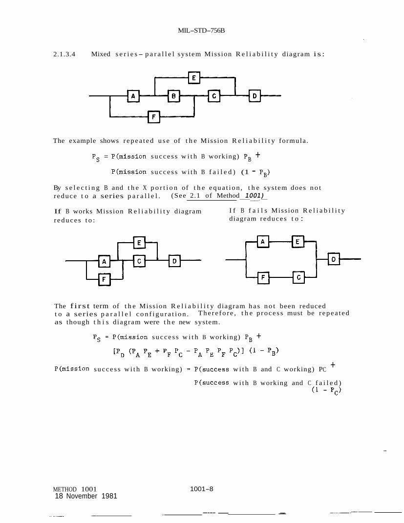
MIL-STD-756B
2.1.3.4 Mixed s e r i e s - p a r a l l e l sys tem Miss ion R e l i a b i l i t y d iagram is :
The example shows r e p e a t e d u s e of t h e Miss ion R e l i a b i l i t y formula .
Ps = P(miss ion s u c c e s s w i t h B working) PB + P(miss ion s u c c e s s w i t h B f a i l e d ) (1 - PB)
By s e l e c t i n g B and t h e X p o r t i o n of t h e e q u a t i o n , t h e sys tem does n o t r educe t o a series p a r a l l e l .
If B works Miss ion R e l i a b i l i t y diagram r e d u c e s t o :
(See 2.1 of Method 1001) -__.-
I f B f a i l s Miss ion R e l i a b i l i t y diagram reduces t o :
The f irst term of t h e Miss ion R e l i a b i l i t y d iagram h a s n o t been reduced t o a series p a r a l l e l c o n f i g u r a t i o n . as though t h i s d iagram were t h e new system.
T h e r e f o r e , t h e p r o c e s s must be r e p e a t e d
Ps = P(miss ion s u c c e s s w i t h B working) PB +
P(miss ion s u c c e s s w i t h B working) = P ( s u c c e s s w i t h B and C working) P + C
P(success w i t h B working and C f a i l e d ) ( 1 - Pc>
1001-8 METHOD 1001 18 November 1981
.--- I--.- ---- - __ - -

MIL-STD-756B
P(success wi th B working and C f a i l e d ) = PA PE PD
P(success with B and C working) = (PA + PF - PA PF) PD
S u b s t i t u t i n g we ge t P = (PA + PF - PA PF)PD Pc + PA PD PE (1 - Pc) PB -t S [ 3
pE + PF PC - PE pF 'C)PD (l - pB) (20)
The equiva len t Basic R e l i a b i l i t y mathematical model f o r t h i s system is :
2 .2 Mult i funct ioned systems, Mult i funct ioned systems can be t r e a t e d s i m i l a r l y t o s ingle-funct ioned systems i f one of t h e fol lowing a p p l i e s :
a. If no equipment appears i n more than one func t ion .
b. If func t ions are t i m e independent, i .e . , they are e i t h e r t i m e sequenced func t ions o r they are never used s imultaneously.
I f e i t h e r (a ) o r (b) above a p p l i e s , t he procedure i s as fol lows:
Treat each func t ion s e p a r a t e l y as descr ibed under s i n g l e funct ioned systems. For t he system, t h e func t ions are t r e a t e d as equipments and can be combined i n series o r p a r a l l e l depending on t h e requirements. The r e s u l t a n t diagram i s t r e a t e d as a s i n g l e funct ioned system. func t ion can be compared with a r e l i a b i l i t y requirement f o r t h a t func t ion i f des i r ed .
Each separate
When an equipment appears i n several func t ions , t h e func t ions cannot be t r e a t e d sepa ra t e ly . The fol lowing example i l l u s t r a t e s t h e po in t .
A system has two func t ions . success and t h e second func t ion r e q u i r e s B o r C f o r success . Both func t ions are requi red f o r mission success . f o r Function 1, Function 2 , and t h e system are shown below.
The f i r s t func t ion r e q u i r e s A o r B f o r
Mission R e l i a b i l i t y diagrams
Function 1 Function 2
Assuming
PA = 0.9
PB = 0.8
P c = 0.7
System
1001-9 METHOD 1001 18 November 1981

MIL-STP-756B
Then the reliability of the function would be
Function 1 = 0.9 + 0.8 - (0.9) (0.8)
= 0.98
Function 2 = 0.8 + 0.7 - (0.8) (0.7)
= 0.94
Mission Reliability cannot be derived by multiplying function reliabilities because of the counnon element B.
Mission Reliability # (0.98) (0.94) = 0.9212
Mission Reliability = PB + PA Pc - PA PB PC = (0.8) + (0.9) (0.7) - (0.9) (0.8) (0.7) (22)
= 0.926
The equivalent Basic Reliability mathematical model for this system is (5) and the Basic Reliability is 0.504.
2.2.1 Conventional probability method.
Ps can be written directly
This equation must be reduced before inserting the probabilities for the various equipments. This is the basic difference between using this method for single and multifunctioned systems.
Reduce the equation by multiplying terms
Where the same,probability appears twice in a term delete one of the common factors.
METHOD 1001 18 November 1981
1001-10
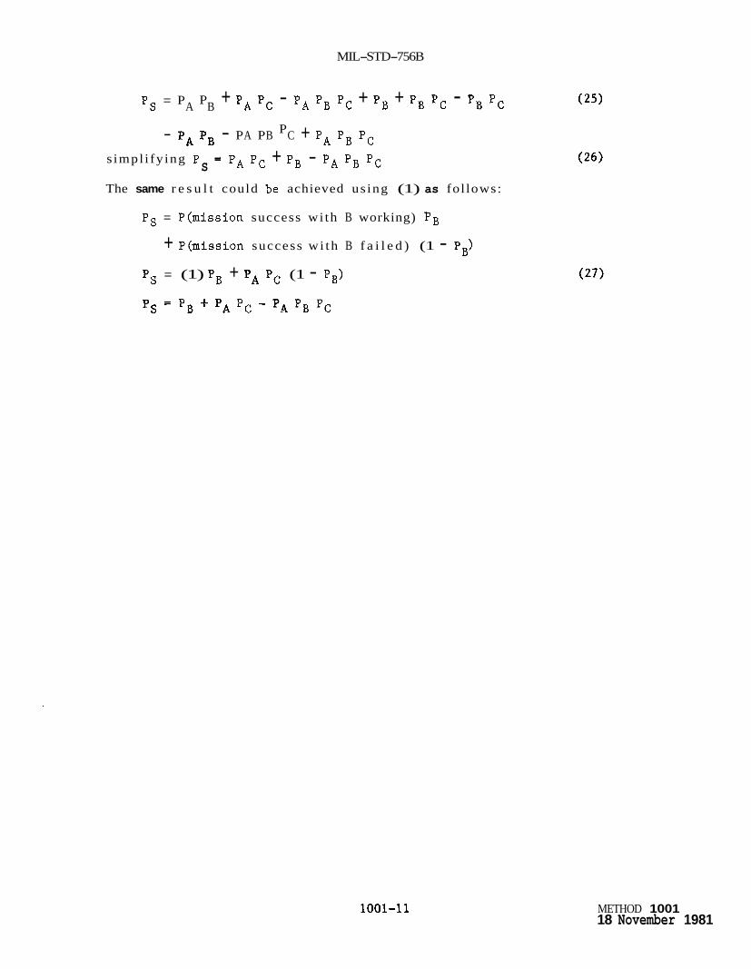
MIL-STD-756B
Ps = P P A B + PA Pc - PA PB Pc + PB + PB Pc - PB Pc
- P A P B - P A B C P + PA PB Pc P
s impl i fy ing P
The same r e s u l t could be achieved us ing (1) as fol lows:
= PA Pc + PB - PA Pg Pc S
Ps = P(mission success wi th B working) PB
+ P(mission success w i th B f a i l e d ) (1 - P,)
Ps = (1) PB + PA Pc (1 - PB)
Ps = PB + PA PC - PA PB PC
1001-11 METHOD 1001 18 November 1981


MIL-STD-756B
METHOD 1002
BOOLEAN TRUTH TABLE
1. PURPOSE. prepare a r e l i a b i l i t y mathematical model from a r e l i a b i l i t y block diagram by means of Boolean a lgebra . t o s i n g l e funct ioned and mul t i func t ioned systems. t ed ious than t h e convent ional p r o b a b i l i t y method bu t i s u s e f u l when t h e r e i s f a m i l i a r i t y wi th Boolean algebra.
2. PROCEDURE.
The purpose of t h e Boolean Truth Table method is t o
The Boolean Truth Table method i s app l i cab le This method i s more
2.1 S ing le funct ioned systems. S ing le funct ioned systems c o n s i s t of equipments considered t o have a s i n g l e func t ion a s soc i a t ed w i t h equipment performance. diagram can t ake t h e form of equipments connected i n series, p a r a l l e l , s e r i e s- p a r a l l e l , o r a complex conf igura t ion . A l t e rna t e modes of ope ra t ion can be considered i n s i n g l e funct ioned system models. system Basic R e l i a b i l i t y diagram can only be a series conf igu ra t ion i n which any equipments provided f o r redundancy o r a l t e r n a t e modes of ope ra t ion f o r mission success are modeled i n series. t h e Boolean Tru th Table approach is i l l u s t r a t e d by t h e fol lowing example. The Mission R e l i a b i l i t y diagram is given as:
The s i n g l e funct ioned system Mission R e l i a b i l i t y
The s i n g l e funct ioned
The procedure f o r
given :
PA = 0.3 1 - P = 0.7 A
PB1 = PB2 = 0.1 and the re f o r e 1 - Pg = 0.9
= P = 0.2 pcl c2 1 - P = 0.8
C
The Boolean a lgebra approach l ists a l l equipments i n a t r u t h t a b l e form (See Table 1002-IL number of equipments i n t h e system. each column i n d i c a t i n g success o r f a i l u r e r e s p e c t i v e l y on each equipment. A l l p o s s i b l e combinations of a l l equipments working and f a i l i n g are thus l i s t e d . The procedure is t o examine each row of t h e t r u t h t a b l e and dec ide whether t he combination of equipments working and f a i l e d y i e l d s system success(S) o r f a i l u r e ( F ) . I n s e r t an S o r F r e s p e c t i v e l y i n t h e nex t column i n t h e t ab l e . For each S en t ry , mu l t ip ly t h e r e s p e c t i v e p r o b a b i l i t i e s f o r t he ind ica t ed s ta te of each equipment t o y i e l d a P s f o r t h a t entry.
,me t r u t h t a b l e has 2" e n t r i e s where n i s t h e The t a b l e has a 1 o r 0 e n t r y i n
1002-1 METHOD 1002 18 November 1981
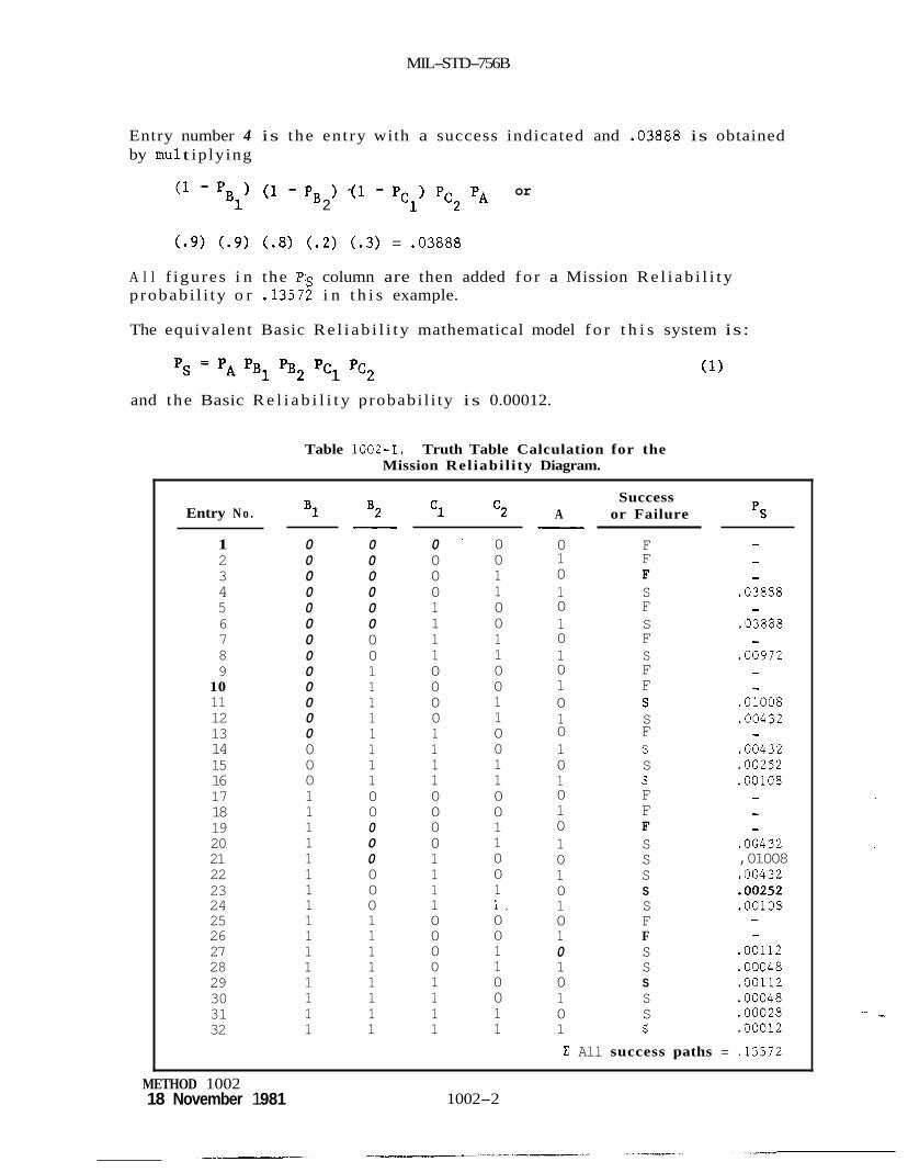
MIL-STD-756B
Entry number 4 is the ent ry with a success indicated and .03888 is obtained by mu1 t ip ly ing
(1 - P (1 - PB ) -(I - Pcl) Pc2 PA or B1 2
( . 9 ) (.9) (.8) (.2) (.3) = .03888
A l l f igures i n the Ps column are then added f o r a Mission R e l i a b i l i t y p robab i l i ty o r .13572 i n t h i s example.
The equivalent Basic R e l i a b i l i t y mathematical model f o r t h i s system is:
and the Basic R e l i a b i l i t y probabi l i ty is 0.00012.
Table 1002-1. Truth Table Calculation for the Mission Rel iabi l i ty Diagram.
Entry N o .
1 2 3 4 5 6 7 8 9
10 11 12 13 14 15 16 17 18 19 20 21 22 23 24 25 26 27 28 29 30 31 32
B1
0 0 0 0 0 0 0 0 0 0 0 0 0 0 0 0 1 1 1 1 1 1 1 1 1 1 1 1 1 1 1 1
B2 - 0 0 0 0 0 0 0 0 1 1 1 1 1 1 1 1 0 0 0 0 0 0 0 0 1 1 1 1 1 1 1 1
c1 c2
0 0 0 0 1 1 1 1 0 0 0 0 1 1 1 1 0 0 0 0 1 1 1 1 0 0 0 0 1 1 1 1
0 0 1 1 0 0 1 1 0 0 1 1 0 0 1 1 0 0 1 1 0 0 1 1 . 0 0 1 1 0 0 1 1
Success A or Failure pS -
- 0 F 1 F - 0 F - 1 S .03888 0 F - 1 S .03888 0 F - 1 S .00972 0 F - 1 F -
.01008 0 S 1 S .00432 0 F - 1 S .00432 0 S .00252 1 S .00108 0 F - 1 F - 0 F - 1 S .00432
,01008 0 S .00432 1 S
0 S -00252 1 S -00108 0 F 1 F
.00112 0 S 1 S .00048 0 S .00112 1 S .00048
.00028 0 S
.00012 1 S
C All success paths = .13572
- -
METHOD 1002 18 November 1 981 1002-2
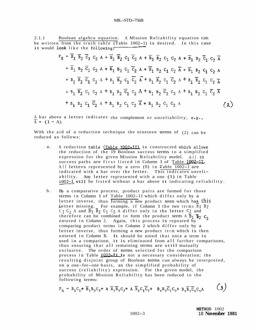
MIL-STD-756B
2.1.1 Boolean a lgebra equat ion. A Mission R e l i a b i l i t y equat ion can be w r i t t e n from t h e t r u t h t a b l e (Table 1002-1) is des i r ed . I n t h i s case i t would look l i k e t h e following:
- - + B1 z2 Fl C2 A + B1 x2 C1 C2 A + B1 z2 C1 c2 A + B1 B2 C1 C2
- - -t- B1 y2 C1 C2 A + B1 B2 Tl C2 A + B1 B2 Tl C2 A + B1 B2 C1 C2 A
+ B1 B2 C1 c2 A + B1 B2 C1 C2 A+ B1 B2 C1 C2 A (2)
A b a r above a l e t te r i n d i c a t e s t he complement o r u n r e l i a b i l i t y , e.g., - A = (1 - A).
With t h e a i d of a reduct ion technique t h e n ine teen terms of (2) can be reduced as fol lows:
a. A r educ t ion t a b l e (Table 1007-TTL is cons t ruc ted which a l lows t h e reduct ion of t h e 19 Boolean success terms t o a s imp l i f i ed express ion f o r t h e given Mission R e l i a b i l i t y model. success pa ths are f i r s t l i s t e d i n Column 1 of Table lQ(&IL. A l l let ters represented by a zero (0) i n Table * 1002-1 are ind ica t ed wi th a bar over t h e let ter . This i n d i c a t e s u n r e l i- a b i l i t y . l-will be l i s t e d without a bar above i t i n d i c a t i n g r e l i a b i l i t y .
A l l 19
Any le t ter represented wi th a one (1) i n Table
b. By a comparative process , product p a i r s are formed f o r those terms i n Column 1 of Table 1002-11 which d i f f e r only by a l e t t e r inverse , thus forming a new product term which hag this - l e t t e r missing. C 1 C 2 A and g1 gz C 1 C2 A d i f f e r on ly i n t h e le t ter C l and t h e r e f o r e can be combined t o form t h e product term A en tered i n Column 2. Again, t h i s process is repea ted by comparing product terms i n Column 2 which d i f f e r only by a l e t t e r inverse , thus forming a new product t e r m which i s then en tered i n Column 3. used i n a comparison, i t is e l imina ted from a l l f u r t h e r comparisons, t hus ensuring t h a t a l l remaining terms are s t i l l mutually exc lus ive . The o rde r of terms s e l e c t e d f o r t h e comparison process i n Table J Q Q L L L i s not a necessary cons ide ra t ion ; t h e r e s u l t i n g d i s j o i n t group of Boolean terms can always be i n t e r p r e t e d , on a one-for-one b a s i s , as t h e s imp l i f i ed p r o b a b i l i t y of success ( r e l i a b i l i t y ) expression. For t h e given model, t h e p r o b a b i l i t y of Mission R e l i a b i l i t y has been reduced t o t h e fol lowing terms:
For example, i f Column 1 t h e two t e r m s B 1 B2
3 2 C2
It should be noted t h a t once a term is
1002-3 METHOD 1002 18 November 1981

c
MIL-STD-756B
B1
B1
B1
B1
c1
c1
c1
c1
- A A 3 B1
B1
c1
c1
- A
A B1
B1 B2 C1 c2 B1 B2 C1 F2 A
B1 B2 C1 C2 7- B1 B2 c1 c2 B1 B2 c1 c2 A
METHOD 1002 18 November 1981 1002-4

MIL-STD-756B
c. S u b s t i t u t i n g t h e r e l i a b i l i t i e s and u n r e l i a b i l i t i e s used previous ly i n t o (3), w e ob ta in :
P:s = ( - 1 ) ( - 2 ) + ( - 9 ) ( - 1 ) ( .2) + ( - 3 ) ( - 9 ) (.9) ( - 2 ) + ( - 3 ) ( . 9 ) ( .2) (.8)
+ (.1) (.1) (.8) ( .2) + (.1) (.9) (.8) ( .2) ( . 3 ) = .13572 which i s
t h e same p r o b a b i l i t y of success shown i n t h e summation f o r Table 1002-1. -
2.2 Mult i funct ioned systems. Mult i funct ioned systems can be t r e a t e d s i m i l a r l y t o s i n g l e funct ioned systems i f one of t h e fol lowing a p p l i e s :
a. I f no equipment appears i n more than one func t ion .
b. I f func t ions are t i m e independent, i . e . , they are e i t h e r t i m e sequenced func t ions o r they are never used s imultaneously.
If e i t h e r (a) o r (b) above app l i e s , t h e procedure is as fol lows:
Treat each func t ion s e p a r a t e l y as descr ibed under s i n g l e funct ioned systems. be combined i n series o r p a r a l l e l depending on the requirements. r e s u l t a n t diagram is t r e a t e d as a s i n g l e funct ioned system. func t ion can be compared wi th a r e l i a b i l i t y requirement f o r t h a t func t ion i f des i red .
For t h e system, t h e func t ions are t r e a t e d as equipments and can The
Each s e p a r a t e
When an equipment appears i n s e v e r a l func t ions , t h e func t ions cannot be t r e a t e d sepa ra t e ly . The fol lowing example i l l u s t r a t e s t h e po in t .
A system has two func t ions . The f i r s t func t ion r e q u i r e s A o r B f o r success and t h e second func t ion r e q u i r e s B o r C f o r success . Both func t ions are r equ i r ed f o r mission success. Mission R e l i a b i l i t y diagrams f o r Function 1, Function 2 , and t h e system are shown below:
Function 1 Function 2
Assuming
P A = 0.9
Pk = 0.8
P c = 0.7
Then t h e r e l i a b i l i t y of t h e func t ion would be
1002-5
System
METHOD 1002 18 November 1981

MIL-STD-756B
A
0 0 0 0 1 1 1 1
Function 1 = 0.9 + 0.8 - (0.9) (0.8) = 0.98
B C Success or Failure
0 0 F 0 1 F - 1 0 5 .024 1 1 5 -056 0 0 F - 0 1 5 .126 1 0 5 .216 1 1 5 .504
-
Function 2 = 0.8 + 0.7 - (0.8) (0.7)
TOTAL
= 0.94
.926
Mission R e l i a b i l i t y cannot be der ived by multzplying func t ion r e l i a b i l i t i e s because of t h e common element B.
Mission R e l i a b i l i t y # (0.98) (0.94) = 0.9212
Mission R e l i a b i l i t y = PB + PA Pc - PA PB Pc = (0.8) + (0.9) (0.7) - (0.9) (0.8) (0.7) (4)
= 0.926
The Boolean Tru th Table s o l u t i o n is:
The equiva len t Basic R e l i a b i l i t y mathematical model f o r t h i s system is:
(5) P s = P P P A B C
The Basic R e l i a b i l i t y i s 0.504.
METHOD 1002 18 November 1981
1002-5
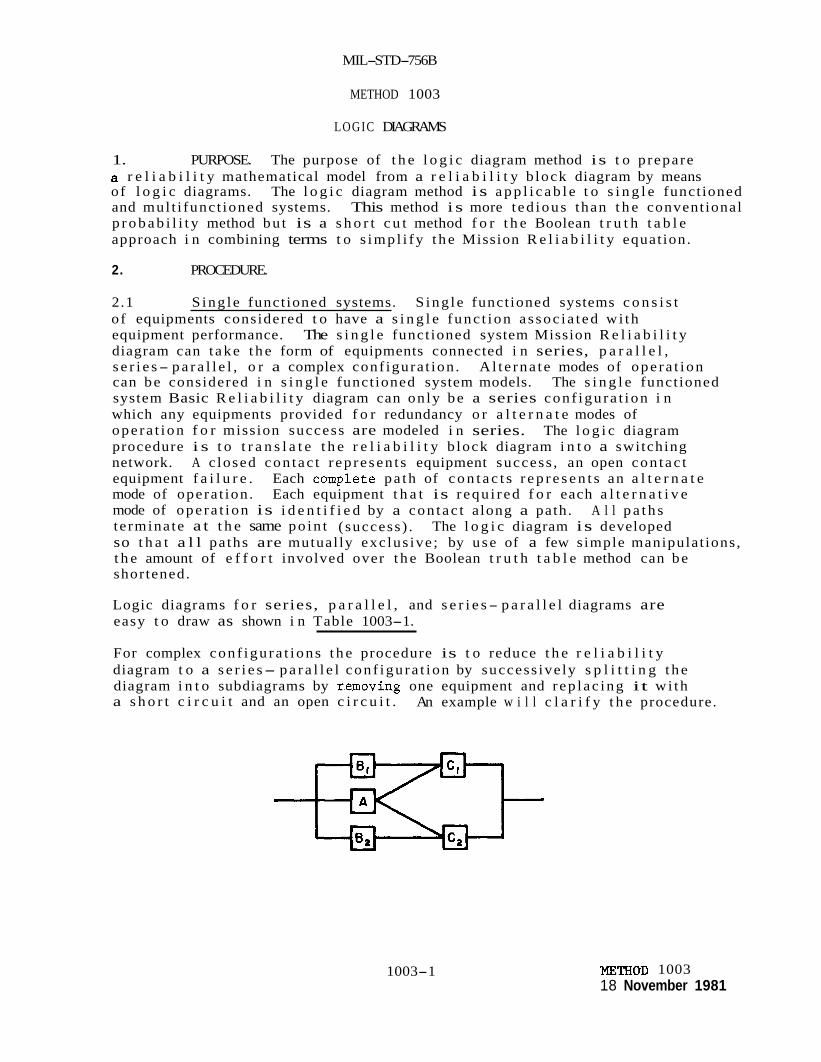
MIL-STD-756B
METHOD 1003
LOGIC DIAGRAMS
1. PURPOSE. The purpose of t h e l o g i c diagram method is t o prepare a r e l i a b i l i t y mathematical model from a r e l i a b i l i t y b lock diagram by means of l o g i c diagrams. and mul t i func t ioned systems. p r o b a b i l i t y method bu t is a s h o r t c u t method f o r t h e Boolean t r u t h t a b l e approach i n combining terms t o s imp l i fy t h e Mission R e l i a b i l i t y equat ion.
The l o g i c diagram method i s a p p l i c a b l e t o s i n g l e funct ioned This method i s more t ed ious than t h e convent ional
2. PROCEDURE.
2.1 S ing le funct ioned systems. S ing le funct ioned systems c o n s i s t o f equipments considered t o have a s i n g l e func t ion a s soc i a t ed wi th equipment performance. diagram can t ake t h e form of equipments connected i n series, p a r a l l e l , s e r i e s- p a r a l l e l , o r a complex conf igura t ion . A l t e rna t e modes of ope ra t ion can be considered i n s i n g l e funct ioned system models. The s i n g l e funct ioned system Basic R e l i a b i l i t y diagram can only be a series conf igu ra t ion i n which any equipments provided f o r redundancy o r a l t e r n a t e modes of ope ra t ion f o r mission success are modeled i n series. procedure i s t o t r a n s l a t e t h e r e l i a b i l i t y b lock diagram i n t o a switching network. A c losed con tac t r ep re sen t s equipment success , an open con tac t equipment f a i l u r e . mode of opera t ion . Each equipment t h a t is r equ i r ed f o r each a l t e r n a t i v e mode of ope ra t ion is i d e n t i f i e d by a con tac t a long a path. t e rmina te a t t h e same po in t ( success) . so t h a t a l l pa ths are mutual ly exc lus ive ; by use of a few simple manipulat ions, t h e amount of e f f o r t involved over t h e Boolean t r u t h t a b l e method can be shortened.
The s i n g l e funct ioned system Mission R e l i a b i l i t y
The l o g i c diagram
Each complete pa th of c o n t a c t s r e p r e s e n t s an a l t e r n a t e
A l l p a t h s The l o g i c diagram is developed
Logic diagrams f o r series, p a r a l l e l , and s e r i e s- p a r a l l e l diagrams are easy t o draw as shown i n Table 1003-1.
For complex conf igu ra t ions t h e procedure is t o reduce t h e r e l i a b i l i t y diagram t o a s e r i e s- p a r a l l e l con f igu ra t ion by success ive ly s p l i t t i n g t h e diagram i n t o subdiagrams by removing one equipment and r ep lac ing it wi th a s h o r t c i r c u i t and an open c i r c u i t . An example w i l l c l a r i f y t h e procedure.
1003-1 mTHOD 1003 18 November 1981

MIL-S TD- 75 6B
Table 1003-1. Logic Diagram Examples
MISS ION RE L I ABILITY DIAGRAM m
~~
OTHER SERIES PARALLEL COMBINATIONS I CAN BE QUITE SIMPLY DRAWN.
LOGIC DIAGRAM
NOTE: When one log ic switch A i s open, a l l must be open and a l l x m v s t be closed and similarly for B and C log ic switches.
METHOD 1003 18 November 1981
1003-2
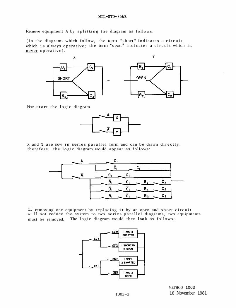
Remove equipment A by s p l i t t i n g - t h e diagram as fol lows:
( I n t h e diagrams which fol low, t h e term " short" i n d i c a t e s a c i r c u i t which i s always ope ra t ive ; t h e term "open'' i n d i c a t e s a c i r c u i t which is never o p e r a t i v e ) .
X
SHORT
Y
Now start t h e l o g i c diagram
X and Y are now i n series p a r a l l e l form and can be drawn d i r e c t l y , t he re fo re , t h e l o g i c diagram would appear as fol lows:
If removing one equipment by r ep lac ing i t by an open and s h o r t c i r c u i t w i l l no t reduce t h e system t o two series p a r a l l e l diagrams, two equipments must be removed. The l o g i c diagram would then look as fo l lows:
1003-3
METHOD 1003 18 November 1981

MIL-STD-756B
A f t e r t h e l o g i c diagram is drawn, two approaches are p o s s i b l e f o r a numerical answer. of success , PS, by w r i t i n g down every pa th wi th an a d d i t i o n s i g n j o i n i n g a l l paths . The second approach is t o i n s e r t va lues f o r t h e va r ious p r o b a b i l i t i e s d i r e c t l y i n t o t h e l o g i c diagram and mul t ip ly series terms and add p a r a l l e l terms u n t i l j u s t one series term remains. This r e s u l t is t h e answer. For t h e above example:
The f i r s t involves w r i t i n g an equat ion f o r t h e p r o b a b i l i t y
- - = A [Cl + c1 C 2 ] + [B1 C1 + B1 C1 B2 C2 + B1 c1 B2 c2 pS
2.2 Mult i funct ioned systems. Mult i funct ioned systems can b e t r e a t e d s i m i l a r l y t o s ingle- funct ioned systems i f one of t h e fol lowing a p p l i e s :
a. I f no equipment appears i n more than one func t ion .
b. I f func t ions are t i m e independent, i .e. , they are e i t h e r t i m e sequenced func t ions or they are never used s imultaneously.
I f e i t h e r (a) o r (b) above a p p l i e s , t h e procedure is as fol lows:
Treat each func t ion s e p a r a t e l y as descr ibed under s i n g l e funct ioned systems. For t h e system, t h e func t ions are t r e a t e d as equipments and can be combined i n series o r p a r a l l e l depending on t h e requirements . The r e s u l t a n t diagram is t r e a t e d as a s i n g l e funct ioned system. Each s e p a r a t e func t ion can be compared wi th a r e l i a b i l i t y requirement f o r t h a t func t ion i f des i red .
When an equipment appears i n several func t ions , t h e func t ions cannot be t r e a t e d sepa ra t e ly . The fol lowing example i l l u s t r a t e s t h e po in t .
A system has two func t ions . success and t h e second func t ion r e q u i r e s B o r C f o r success . func t ions are requi red f o r mission success. f o r Function 1, Function 2, and t h e system are shown below.
The f i r s t func t ion r e q u i r e s A o r B f o r Both
Mission R e l i a b i l i t y diagrams
Function 1
Assuming
P* = 0.9
PB = 0.8
Pc = 0.7 METHOD 1003 18 November 1981
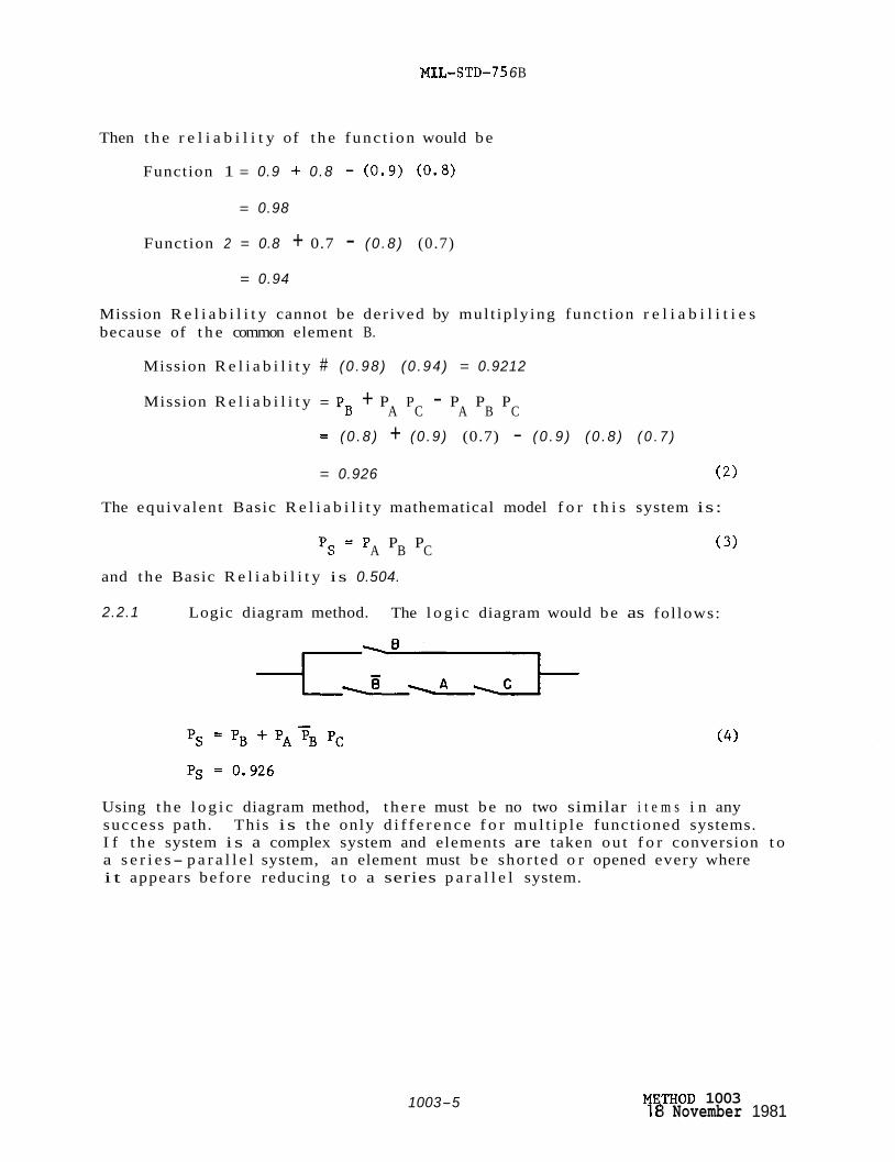
MIL- STD-7 5 6 B
Then t h e r e l i a b i l i t y of t h e func t ion would be
Function 1 = 0.9 + 0.8 - ( 0 . 9 ) ( 0 . 8 )
= 0.98
Function 2 = 0.8 + 0.7 - ( 0 . 8 ) (0.7)
= 0.94
Mission R e l i a b i l i t y cannot be der ived by mul t ip ly ing func t ion r e l i a b i l i t i e s because of t h e common element B.
Mission R e l i a b i l i t y # (0 .98 ) (0 .94 ) = 0.9212
Mission R e l i a b i l i t y = PB + P P - P P P A C A B C
= ( 0 . 8 ) + (0 .9 ) (0.7) - ( 0 . 9 ) ( 0 . 8 ) ( 0 . 7 )
= 0.926 ( 2 )
The equiva len t Basic R e l i a b i l i t y mathematical model f o r t h i s system is:
P s = P P P A B C
and the Basic R e l i a b i l i t y is 0.504.
( 3 )
2.2.1 Logic diagram method. The l o g i c diagram would be as fol lows:
Using t h e l o g i c diagram method, t h e r e must be no two similar i t e m s i n any success path. This is the only d i f f e r e n c e f o r mu l t ip l e funct ioned systems. I f t h e system i s a complex system and elements are taken ou t f o r conversion t o a s e r i e s- p a r a l l e l system, an element must b e shor ted o r opened every where i t appears before reducing t o a series p a r a l l e l system.
1003-5 "HOD 1003 T 8 November 1981


MIL-STD-756B
METHOD 1004
MONTE CARL0 SIMULATION
1. PURPO E. The purpose of t h e Monte C a r a s imula t ion method is t o synthes ize a system r e l i a b i l i t y p r e d i c t i o n from a r e l i a b i l i t y block diagram by means of random sampling. The Monte Carlo s imula t ion method i s employed i n i n s t ances where ind iv idua l equipment p r o b a b i l i t i e s (or equiva len t r e l i a b i l i t y parameter) are known b u t t h e mission r e l i a b i l i t y model i s exceedingly complex t o d e r i v e a genera l equat ion f o r s o l u t i o n . The Monte Carlo s imula t ion method does not r e s u l t i n a genera l p r o b a b i l i t y of success equat ion bu t computes t h e system p r o b a b i l i t y of success from t h e ind iv idua l equipment p r o b a b i l i t i e s and t h e r e l i a b i l i t y block diagram. A Monte Carlo s imula t ion can be performed manually b u t is inva r i ab ly performed by computer due t o t h e l a r g e number of r e p e t i t i v e tr ials and c a l c u l a t i o n s requi red t o o b t a i n a s i g n i f i c a n t r e s u l t . The Monte Carlo s imula t ion method i s app l i cab le t o s i n g l e funct ioned and mul t i func t ioned systems.
2. PROCEDURE.
2.1 S ing le funct ioned systems. S ing le funct ioned systems c o n s i s t of equipments considered t o have a s i n g l e func t ion a s soc i a t ed wi th equipment performance. The s i n g l e funct ioned system Mission R e l i a b i l i t y diagram can t ake t h e form of equipments connected i n series, p a r a l l e l , s e r i e s- p a r a l l e l , o r a complex conf igura t ion . A l t e rna t e modes of ope ra t ion can be considered i n s i n g l e funct ioned system models. The s i n g l e funct ioned system Basic R e l i a b i l i t y diagram can only be a series conf igura t ion i n which any equipments provided f o r redundancy o r a l ternate modes of ope ra t ion f o r mission success are modeled i n series.
The Monte Carlo s imula t ion procedure is t o determine t h e d i s t r i b u t i o n of a func t ion of one o r more v a r i a b l e s from t h e d i s t r i b u t i o n of t h e ind iv idua l v a r i a b l e s . The method involves random sampling from t h e d i s t r i b u t i o n s of a l l v a r i a b l e s and i n s e r t i n g t h e va lues so obta ined i n t h e equat ion f o r t h e func t ion of i n t e r e s t . success d i s t r i b u t i o n is t o be est imated i s P(x X 2 ..., X, are independent random v a r i a b l e s whose d i s t r i b u t i o n s are presumed t o be known. from t h e d i s t r i b u t i o n s of t h e X ' s , c a l c u l a t e P f o r t h a t set, and s t o r e t h a t va lue of P. The procedure is repeated many t i m e s u n t i l enough va lues of P are obtained. From t h i s sample of P va lues , i t s d i s t r i b u t i o n and parameters can be est imated.
Suppose t h e func t ion whose p r o b a b i l i t y of xn) and t h a t t h e Xi,
The procedure is t o p ick a set of x's randomly
The Monte Carlo s imula t ion method i s based on several p r i n c i p l e s of p r o b a b i l i t y and on the techniques of p r o b a b i l i t y t ransformation. One of t h e underlying p r i n c i p l e s i s t h e l a w of l a r g e numbers, which states t h a t t h e l a r g e r t h e sample t h e more c e r t a i n l y the sample mean w i l l b e a good estimate of t h e populat ion mean. The procedure f o r t h e Monte Carlo s imula t ion method is i l l u s t r a t e d by t h e fol lowing example. The Mission R e l i a b i l i t y diagram is given as:
1004-1 METHOP 1004 18 November 1981

MIL-STD-756B
given:
PA = 0.3
= P = 0.1
= P = 0.2 pB1 B2
pC1 c2 Select a random number between 0.01 and 1.00 from a table of random numbers or generated by a computer. random number is equal to or less than 0.3 then equipment A is a success. Once success (S) or failure (F) is determined, it is recorded as in Table 1004-1 and the procedure is repeated for equipments B1, B2, C1 and C2. A new random number for each equipment is used to compare against that equipment and results are recorded. If a success path can be found among the failed and nonfailed equipments then the system function is determined to be a success.
Table 1004-rdisplays the outcome of ten trials of a typical Monte Carlo kimulation. In this particular outcome, there was one system success for the ten trials (trial 8) resulting in Ps = 0.10. the random numbers generated, the success/failure array may differ from simulation to simulation and the number of system successes may vary for any fixed number of trials. However, as the number of trials increase, the ratio of system successes to trials should approach the actual PS of 0.13572. The degree of Monte Carlo precision is determined by the number of trials conducted. Typically, a minimum of 100 trials is required.
Compare the random number with PA. If the
- Ps is the ratio of system successes to trials.
Depending upon
The equivalent Basic Reliability mathematical model for this system is:
and the Basic Reliability probability is 0.00012.
2.2 Multifunctioned systems. Multifunctioned systems can be treated similarly to single-functioned systems if one of the following applies:
a. If no equipment appears in more than one function.
b. If functions are time independent, i.e., they are either time sequenced functions or they are never used simultaneously.
METHOD 1004 18 November 1981 1004-2

MIL-STD- 7 5 6B
Table 1004-1. Success /Fa i lure Array f o r t h e Mission R e l i a b i l i t y Diagram.
T r i a l No. A B1 B2 c1 c2 System
1 S F S F F F
2 F F F F S F
3 S F F F F F
4 F F F F F F
5 S F F F F F
6 F F F F F F
7 F F F F S F
8 S F S F S S
9 F F F F F F
10 F S F F F F h
0.10 Ps - -== NOTE: This i s only one poss ib l e a r r a y and one p o s s i b l e outcome among
many t h a t can r e s u l t from a Monte Carlo s imula t ion of ten t r ia ls . Addi t iona l t r ials are requi red t o ob ta in meaningful p rec i s ion wi th which t h e Monte Carlo r e s u l t w i l l approximate t h e a c t u a l answer.
I f e i t h e r (a) o r (b) a p p l i e s , t h e procedure is as fol lows:
Treat each func t ion s e p a r a t e l y as described under s i n g l e funct ioned systems. For t h e system, t h e func t ions are t r e a t e d as equipments and can be combined i n series o r p a r a l l e l depending on t h e requirements . The r e s u l t a n t diagram i s t r e a t e d as a s i n g l e funct ioned system. Each s e p a r a t e func t ion can be compared wi th a r e l i a b i l i t y requirement f o r t h a t func t ion i f des i red .
When an equipment appears i n several func t ions , t h e func t ions cannot be t r e a t e d sepa ra t e ly . The fol lowing example i l l u s t r a t e s t h e po in t .
A system has two func t ions . The f i r s t func t ion r e q u i r e s A o r B f o r success and t h e second func t ion r e q u i r e s B o r C f o r success . Both func t ions are requi red f o r mission success . Mission R e l i a b i l i t y diagrams f o r Function 1, Function 2, and t h e system are shown as fol lows.
1004-3 METHOD 1004 18 November 1 981

MTL-STD-756B
Function 1
Assuming
Function 2 System
Pc = 0.7
Then the reliability of the function would be
Function 1 = 0.9 + 0.8 - (0.9) (0.8)
= 0.98
Function 2 = 0.8 + 0.7 - (0.8) (0.7)
= 0.94
Mission Reliability cannot be derived by multiplying function reliabilities because of the common element B.
Mission Reliability # (0.98) (0.94) = 0.9212
Mission Reliability = PB + PA Pc - PA PB Pc
= (0.8) + (0.9) (0.7) - (0.9) (0.8) (0.7) (2)
= 0.926
The equivalent Basic Reliability mathematical model for this system is:
Ps = PA PB Pc
and the Basic Reliability is 0.504.
2.2.1 Monte Carlo simulation method. The Monte Carlo simulation solution based upon ten trials is shown inEble 1004-11. Additional trials are required to better approximate the actual answer of 0.926.
METHOD 1004 18 November 1981 1004-4
(3)
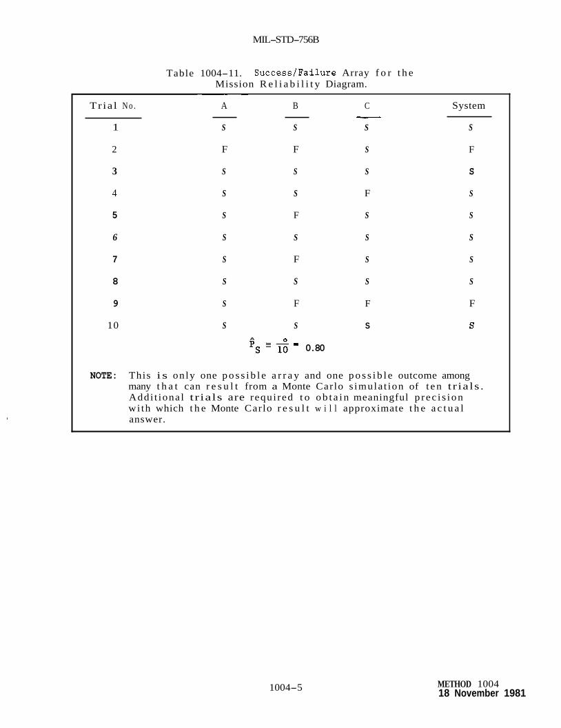
MIL-STD-756B
Table 1004-11. Success /Fa i lure Array f o r t h e Mission R e l i a b i l i t y Diagram.
~~ ~
Tria l N o . A B C System - 1 S S S S
2 F F S F
3 S S S S
4 S S F S
5 S F S S
6 S S S S
7 S F S S
8 S S S S
9 S F F F
10 S S S S A
0.80 P s - n = -
NOTE: This i s only one p o s s i b l e a r r a y and one p o s s i b l e outcome among many t h a t can r e s u l t from a Monte Carlo s imula t ion of t e n t r ia ls . Addi t iona l tr ials are requi red t o o b t a i n meaningful p rec i s ion wi th which t h e Monte Carlo r e s u l t w i l l approximate t h e a c t u a l answer.
1004-5 METHOD 1004 18 November 1981

MIL-STD-756B
METHOD 2001
SIMILAR ITEM METHOD
1 . PURPOSE. This p r e d i c t i o n method u t i l i z e s s p e c i f i c experience on similar i t e m s . compare t h e i t e m under cons idera t ion wi th a s i m i l a r i t e m whose r e l i a b i l i t y has prev ious ly been determined by some means and has undergone f i e l d evaluat ion. i t e m s undergoing o r d e r l y evolu t ion . Not only i s t h e contemplated new des ign s i m i l a r t o t h e o ld design, bu t s m a l l d i f f e r ences can be e a s i l y i s o l a t e d and evaluated. I n add i t i on , d i f f i c u l t i e s encountered i n t h e o ld des ign are s ignpos t s t o improvements i n t h e new des ign . c i r c u i t method should be considered i f a s i m i l a r i t e m comparison cannot be made.
The most rap id way of es t imat ing r e l i a b i l i t y i s t o
Th i s method has a cont inuing and meaningful a p p l i c a t i o n f o r
The similar
2. PROCEDURE.
2.1 inc lude :
Major f a c t o r s f o r a d i r e c t comparison of similar i t e m s should
a.
b.
13.
d.
e.
f .
2 . 2
Item phys i ca l and performance comparison
Design s i m i l a r i t y
Manufacturing s i m i l a r i t y
S i m i l a r i t y of t h e s e r y i c e use p r o f i l e ( l o g i s t i c , o p e r a t i o n a l , and envi roqnenta l )
Program and p r o j e c t s i m i l a r i t y
Proof of r e l i a b i l i t y achievement
The v a l i d i t y of t h e similar i t e m method i s dependent upon t h e degree of equiyalence between t h e items and not simply t h e gene r i c term used t o desc r ibe t h e i t e m s . For example, a l though both are power s u p p l i e s (gener ic t ype ) , t h e achieved r e l i a b i l i t y of a t e n w a t t power supply should not normally be used as a p r e d i c t i o n method f o r a proposed one k i lowa t t power supply as t h e much higher power level of t h e proposed power supply may r e s u l t i n much lower r e l i a b i l i t y achievement due t o des ign d i f f e r e n c e s and stresses. scale f a c t o r s t o r e a l i s t i c a l l y relate r e l i a b i l i t y wi th i t e m parameters such as power levels.
A comparison may be made i f t h e r e are
2.3 GIDEP F a i l u r e Rate Summaries are a d a t a source f o r t h i s method.
2001-1 METHOD 2001 18 November 1981

MIL-STD-756B
METHOD 2002
SIMILAR CIRCUIT METHOD
1. PURPOSE. This p r e d i c t i o n method u t i l i z e s s p e c i f i c experience on similar c i r c u i t s such as o s c i l l a t o r s , d i s c r imina to r ampl i f i e r s , modulators, pu l se t ransforming networks, etc. e i t h e r when only a c i r c u i t i s being considered o r t h e s i m i l a r i t e m method cannot be u t i l i z e d . i s t o compare t h e c i r c u i t s of t h e i t e m under cons ide ra t ion wi th similar c i r c u i t s whose r e l i a b i l i t y has prev ious ly been determined by some means and has undergone f i e l d eva lua t ion . Ind iv idua l c i r c u i t r e l i ab i l i t i e s can be combined i n t o an i t e m r e l i a b i l i t y p red ic t ion . This method has a cont inuing and meaningful a p p l i c a t i o n f o r c i r c u i t s undergoing o r d e r l y evolut ion. design, but s m a l l d i f f e r e n c e s can be e a s i l y i s o l a t e d and evaluated. add i t i on , d i f f i c u l t i e s encountered i n t h e o ld des ign are s ignpos t s t o improvements i n t h e new design.
This method is employed
The most r ap id way of e s t ima t ing r e l i a b i l i t y
Not on ly i s t h e contemplated new des ign similar t o t h e o ld I n
2. PROCEDURE
2.1 should inc lude :
Major f a c t o r s f o r a d i r e c t comparison of similar c i r c u i t s
a. C i r c u i t phys i ca l and performance comparison
b. Design s i m i l a r i t y
c. Manufacturing s i m i l a r i t y
d. S i m i l a r i t y of t h e service use p r o f i l e ( l o g i s t i c , o p e r a t i o n a l , and environmental)
e. Program and p r o j e c t s i m i l a r i t y
f . Proof of r e l i a b i l i t y achievement
2.2 Ind iv idua l c i r c u i t r e l i a b i l i t i e s can be combined i n t o an item r e l i a b i l i t y p r e d i c t ion. be considered when combining ind iv idua l c i r c u i t r e l i a b i l i t i e s i n order t o determine a real is t ic i t e m r e l i a b i l i t y p red ic t ion .
C i r c u i t in te rconnect r e l i ab ’ i l i t y f a c t o r s should
2.3 t h e degree of equivalence between t h e c i r c u i t s and not simply t h e gene r i c term used t o desc r ibe t h e i t . e m s . For example, a l though both are ampl i f i e r c i r c u i t s (gener ic t e r m ) , t h e achieved r e l i a b i l i t y of a one m i l l i w a t t a m p l i f i e r c i r c u i t should not normally be used as a p r e d i c t i o n method f o r a proposed t e n w a t t ampl i f i e r c i r c u i t as t h e much h igher power level of t h e proposed ampl i f i e r c i r c u i t may r e s u l t i n much lower r e l i a b i l i t y achievement due t o des ign d i f f e r e n c e s and stresses. A comparison may be made i f t h e r e are scale f a c t o r s t o r e a l i s t i c a l l y relate r e l i a b i l i t y w i t h i t e m parameters such as power levels.
The v a l i d i t y of t h e s i m i l a r c i r c u i t method i s dependent upon
2002-1 METHOD 2002 18 November 1981

MIL-STD-756B
2.4 Various equipment manufacturers and m i l i t a r y agencies have p re fe r r ed c i r c u i t manuals o r documents wi th a s soc i a t ed f a i l u r e rates which may be u t i l i z e d wi th t h i s type p red ic t ion . GIDEP F a i l u r e Rate Summaries may be a d a t a source f o r t h i s method.
METHOD 2002 18 November 1981
2002-2

MIL-STD-7 56B
METHOD 2003
ACTIVE ELEMENT GROUP METHOD
1. PURPOSE. The Active Element Group (AEG) method is termed a f e a s i b i l i t y es t imat ing procedure because i t is useful f o r gross estimates of a design i n t h e conceJ?_t ~ formulation-and-preldminary " design s tages . l"l_l_ - * x -
Only an estimate of t h e number of series AEGs required to-perform t h e design function is needed. complexity ( a c t i v e element groups) and appl ica t ion environment t o f a i l u r e rates experienced i n f l e e t usage. Available da ta f o r t h i s method fs cur ren t ly l imi ted t o sh ips and ships ' m i s s i l e s .
The AEG method relates item funct ional
2 . DOCUMENTS REFERENCED I N METHOD 2003:
PUBLI CAT IONS
Naval Sea Systems Corrnnand
NAVORD OD 44622 R e l i a b i l i t y Data Analysis and I n t e r p r e t a t i o n Volume 4
3 . DEFINITIONS
3.1 Active element. A p a r t t h a t converts o r con t ro l s energy; e.g., t r a n s i s t o r , diode, e l ec t ron tube, re lay , valve, motor, hydraul ic Pump
3 . 2 Active element group. An active element and its associa ted support ing (passive) p a r t s ; e.g., an ampl i f ie r c i r c u i t , a r e l a y c i r c u i t , a pump and i ts plumbing and f i t t i n g s .
3 . 3 Passive element, i n conjunction with an active element t o perform a des i red function; e.g., capac i to r , r e s i s t o r , f i t t i n g .
Any p a r t , not i t s e l f an a c t i v e element, used
4 . PROCEDURE.
4 . 1 General considerat ions. I n t h e AEG method enough is known about the design so t h a t the number and types of active elements are known o r can be est imates. r e l f a b i l i t y model i n the appl ica t ion of AEG f a i l u r e rates used t o de r ive an item r e l i a b i l i t y predic t fon as AEGs may be u t i l i z e d i n redundant as a l t e r n a t e mode hardware configurat ions. The AEG method i s based on several general ized assumptions which can be summarized as follows:
Consideration must be given t o t h e i t e m
a. All ac t fve elements can be defined and c l a s s i f i e d as represen ta t ive types, and t h e quant i ty of supporting passive elements is e f f e c t i v e l y constant for each type, regardless of t h e end use i t e m .
2003-1 METHOD 2003 18 November 1981

MIL-STD-756B
b. The inaccuracy inherent i n assigning a s i n g l e f a i l u r e rate t o each of t h e active element types i s acceptable.
c. A s i n g l e f a i l u r e rate can be used f o r each generic pass ive element type.
d. The change i n f a i l u r e rate with environmental s e v e r i t y i s i d e n t i c a l f o r a l l p a r t types.
The shaded areas i n Figures 2003-1, 2003-2, and 2003-3 represent upper and lower f a i l u r e - r a t e bounds f o r t h e da ta upon which the f i g u r e s were prepared.
4.2 Detai led Procedure. For each r e l i a b i l i t y block determine if the block's funct ion is primari ly analog, d i g i t a l , o r mechanical. t he na ture of the funct ion is determined, proceed with one of the following s teps .
Once
4.2.1 Elec t ronic Analog Function Fa i lu re Rate Estimation.
4.2.1.1 number of series analog a c t i v e elements necessary t o perform the block's function. Use Table 2003-1 t o convert d i f f e r e n t classes of e l e c t r o n i c AEGs t o equivalent analog A E G s .
For each e l e c t r o n i c analog r e l i a b i l i t y block, determine t h e
4.2,l.Z upon t he number of series equivalent analog AEGs and mission appl ica t ion .
Determine t h e block's f a i l u r e rate from Figure 2003-1 based
Table 2003-1. Weighting Factors f o r Dif ferent Classes of Elec t ronic AEGs Used i n Estimating Analog
Complexity f o r Figure 2003-1.
AEG Type
Analog s i g n a l functions: Trans is tor Electron tube In tegra ted c i r c u i t Diode
Power supply functions: Trans is tor Electron tube Diode ( r e c t i f i e r )
Microwave power tube
D i g i t a l Functions: Trans is tor In tegra ted c i r c u i t Diode
Relays (general)
METHOD 2003 18 November 1981
2003-2
Analog Elec t ronic AEGs
1.0 1.0 1 -0 0.1
2.0 2.0 1.0
100.0
0.1 0.1 0.01
1.0

MIL-STD-756B
a 3 0 I W l-
W a 0
W a v) W
3 -J
a a
a
a
- 2
1
W + a a a W
3 -J - 2
EQUIVALENT ANALOG FUNCTIONAL COMPLEXITY N ACTIVE ELEMENTS
Figure 2003.1. Failure-Rate Estimating Chart for Electronic Analog Function.
2003-3 METHOD 2003
18 November 1981

MIL-STD-756B
4.2.2
4.2.2.1 number of series d i g i t a l active elements necessary t o perform t h e b lock ' s func t ion . Use Table 2003-11 t o convert d i f f e r e n t classes of e l e c t r o n i c AEGs t o equiva len t d i g i t a l AEGs.
E l e c t r o n i c D i g i t a l Function F a i l u r e Rate Est imation
For each e l e c t r o n i c d i g i t a l r e l i a b i l i t y block, determine t h e
4.2.2.2 upon t h e number of series equiva len t d i g i t a l AEGs and mission a p p l i c a t i o n .
Determine t h e b lock ' s f a i l u r e rate from Figure 2003-2 based
4.2.3 Mechanical Devices Function F a i l u r e Rate Est imation
4.2.3.1 number of series mechanical active elements necessary t o perform t h e b lock ' s func t ion . mechanical AEGs t o equiva len t analog AEGs.
For each mechanical device r e l i a b i l i t y block, determine t h e
U s e Table 2003-111 t o conver t d i f f e r e n t classes of
4.2.3.2 upon The number of series equiva len t mechanical analog AEGs and mission app l i ca t ion .
Determine t h e b lock ' s f a i l u r e rate from Figure 2003-3 based
4.2.4 Reference. Addi t iona l d e t a i l s on t h e AEG method are provided i n NAVORD OD 44622, Volume 4 .
METHOD 2003 2003-4 18 November 1981
I-____- __-- _ " - "_____--__--._l__l_-~- - --

MIL-STD-756B
Transistor
a 3 0 I
u a v) W a 3 -I
a
- 2 z W l-
- a a a W
3 J - 2
1.0
I " 102 103 104 105
FUNCTIONAL COMPLEXITY IN DIGITAL AEGs
Figure 2003..2. Failure-Rate Estimation Chart for Digital Electronic Functions.
Table 2003-11. Weighting Factors for Estimating Digital Electronics AEG Complexity for
Use With Figure 2003-2.
AEG Type Digital
Electronic AEGs
Integrated circuit
Diode
1.0
0.1
2003-5 NETHOD 2003 18 November 1981
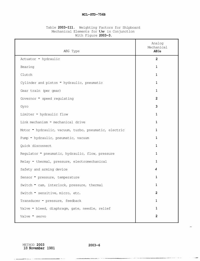
MIL-STD-756B
Table 2003-111. Weighting Factors for Shipboard Mechanical Elements for Use in Conjunction
With Figure 2003-3.
AEG Type
Actuator - hydraulic
Bearing
Clutch
Cylinder and piston - hydraulic, pneumatic Gear train (per gear)
Governor - speed regulating Gyro
Limiter - hydraulic flow
Link mechanism - mechanical drive
Motor - hydraulic, vacuum, turbo, pneumatic, electric Pump - hydraulic, pneumatic, vacuum
Quick disconnect
Regulator - pneumatic, hydraulic, flow, pressure Relay - thermal, pressure, electromechanical
Safety and arming device
Sensor - pressure, temperature Switch - cam, interlock, pressure, thermal Switch - sensitive, micro, etc. Transducer - pressure, feedback
Valve - bleed, diaphragm, gate, needle, relief
Valve - servo
METHOD 2003 18 November 1981
2003-6
Analog Mechanical
AEGs
2
1
1
1
1
2
3
1
1
1
1
1
1
1
4
1
1
2
1
1
2

MIL-STD-756B
10
I
n U
I (2: W a v) W
3
g 10
a
2 10' 2
a a a A 10
Y
W l-
W
3 - 2
10
10
Figure 2003..3. Failure-Rate Estimation Chart for Mechanical Devices.
2003-7 BETHOD 2003 18 November 1981


MIL-STD-756B
METHOD 2004
PARTS COUNT METHOD
1. i n t h e pre l iminary design ---_ s t a g e when t h e number of p a r t s i n each gener ic
G p e class Z i i E E i capaElto?s, r e s i s t o r s , etc., are reasonably f ixed and t h e o v e r a l l des ign complexity is not expected t o change apprec iab ly dur ing later s t a g e s of development and product ion. The p a r t s count method assumes t h e t i m e t o f a i l u r e of t h e p a r t s i s exponent ia l ly d i s t r i b u t e d ( i . e . , a cons tan t f a i l u r e rate).
PURPOSE. The p a r t s count method is a p r e d i c t i o n method used
2. DOCUMENTS REFERENCED I N METHOD 2004:
HANDBOOKS
M i l i t a r y
MIL-HDBK-217
OTHER PUBLICATIONS
RADC-TR-7 3- 248
RADC-TR-74-269
LC-7 8- 1
GIDEP
R e l i a b i l i t y P r e d i c t i o n of E lec t ron ic Equipment
Dormancy and Power On-Off Cycling E f f e c t s on E lec t ron ic Equipment and P a r t R e l i a b i l i t y
E f f e c t s of Dormancy on Nonelectronic Components and Materials
Storage R e l i a b i l i t y of Missile Material Program, Missile Material R e l i a b i l i t y Handbook P a r t s Count P r e d i c t i on
Government Indus t ry Data Exchange Program, Summaries of F a i l u r e Rates
NPRD-1 Nonelectronic P a r t s R e l i a b i l i t y Data, 1978
3. PROCEDURE.
3.1 of p a r t f a i l u r e rates i f a l l elements of t h e i t e m r e l i a b i l i t y model are i n series o r can be assumed i n series f o r purposes of an approximation. I n t h e event t h e i t e m r e l i a b i l i t y model c o n s i s t s of non- series elements (e.g. , redundancies, a l t e r n a t e modes of ope ra t ion ) , i t e m r e l i a b i l i t y can be determined e i t h e r by cons ider ing only t h e series elements of t h e model as an approximation o r by summing p a r t f a i l u r e rates f o r t h e i n d i v i d u a l elements and c a l c u l a t i n g an equiva len t series f a i l u r e rate f o r t h e non- series elements of t h e model.
The item f a i l u r e rate can be determined d i r e c t l y by t h e summation
2004-1 METHOD 2004 18 November 1981

MIL-STD-756B
3.2 inc ludes :
The information needed t o support t h e p a r t s count method
a.
b.
C.
d.
3.3
Generic p a r t types ( inc luding complexity f o r mic roe l ec t ron ic s ) ,
p a r t quan t i t y ,
p a r t q u a l i t y levels (when known o r can be assumed), and
i t e m environment.
The gene ra l express ion f o r i t e m f a i l u r e rate with t h i s method is:
i=n = C N i ( A 7 ~ )
'ITEM i= 1 G Q i
f o r a given i t e m environment where:
Equation (1)
t o t a l f a i l u r e ra te
gene r i c f a i l u r e rate f o r t h e ith gene r i c p a r t
q u a l i t y f a c t o r f o r t h e i t h gene r i c p a r t
q u a n t i t y of i t h gene r i c p a r t
number of d i f f e r e n t gene r i c p a r t c a t e g o r i e s
a p p l i e s t o an e n t i r e i t e m being used i n one environment. If t h e i t e m comprises several u n i t s ope ra t ing i n d i f f e r e n t environments (such as av ion ic s w i th u n i t s i n a i rbo rne , i nhab i t ed , f i g h t e r (AIF) and uninhabi ted, f i g h t e r (AuF) environment), then equat ion (1) should be appl ied t o t h e p o r t i o n s of t h e i t e m i n each environment. These "environment- i t e m " f a i l u r e rates should be added t o determine t o t a l i t e m f a i l u r e rate.
3.4 Qua l i t y f a c t o r s are t o be appl ied t o each p a r t type where q u a l i t y level d a t a e x i s t s o r can be reasonably assumed. levels and d a t a exist f o r p a r t s , such as mic roe l ec t ron ic s , d i s c r e t e semiconductors, and f o r e s t ab l i shed r e l i a b i l i t y (ER) r e s i s t o r s and capac i to r s . t h a t p a r t s are procured i n accordance wi th app l i cab le p a r t s s p e c i f i c a t i o n s .
Mul t i -qua l i ty
For o the r p a r t s such as nonelec t ronics , IT^ = 1 providing
3.5 F a i l u r e ra te d a t a sources such as MIL-HDBK-217, NPRD-1, GLDEP, RADC-TR-73-248, RADC-TR-74-269 and LC-78-1 should be used wi th t h i s method. However, GIDEP should only be used i f t h e p a r t of i n t e r e s t i s no t included i n t h e o the r s t a t e d f a i l u r e ra te sources . Other f a i l u r e rate d a t a sources, inc luding con t r ac to r in-house d a t a , s h a l l r e q u i r e procuring a c t i v i t y approval.
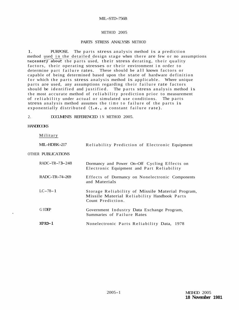
MIL-STD-756B
METHOD 2005
PARTS STRESS ANALYSIS METHOD
1. PURPOSE. The p a r t s stress a n a l y s i s method i s a p red ic t ion method used i n t he d e t a i l e d des ign s t a g e when t h e r e are few o r no assumptions n e c e s s a r a b o u t t h e p a r t s used, t h e i r stress d e r a t i n g , t h e i r q u a l i t y f a c t o r s , t h e i r ope ra t ing stresses o r t h e i r environment i n order t o determine p a r t f a i l u r e rates. capable of being determined based upon t h e s ta te of hardware d e f i n i t i o n f o r which t h e p a r t s stress a n a l y s i s method is app l i cab le . Where unique p a r t s are used, any assumptions regarding t h e i r f a i l u r e rate f a c t o r s should be i d e n t i f i e d and j u s t i f i e d . The p a r t s stress a n a l y s i s method i s t h e most accu ra t e method of r e l i a b i l i t y p r e d i c t i o n p r i o r t o measurement of r e l i a b i l i t y under a c t u a l o r simulated use condi t ions . stress a n a l y s i s method assumes t h e t i m e t o f a i l u r e of t h e p a r t s i s exponent ia l ly d i s t r i b u t e d ( i . e . , a cons tan t f a i l u r e rate) .
These should be a l l known f a c t o r s o r
The p a r t s
2. DOCUMENTS REFERENCED I N METHOD 2005.
HANDBOOKS
M i l i t a r y
MIL-HDBK-217
OTHER PUBLICATIONS
RADC-TR-7 3- 248
RADC-TR-74-269
LC-78- 1
G I DEP
NJ?RD-1
R e l i a b i l i t y P red ic t ion of E lec t ron ic Equipment
Dormancy and Power On-Off Cycling E f f e c t s on E lec t ron ic Equipment and P a r t R e l i a b i l i t y
E f f e c t s of Dormancy on Nonelectronic Components and Materials
S torage R e l i a b i l i t y of Missile Material Program, Missile Material R e l i a b i l i t y Handbook P a r t s Count P red ic t ion .
Government Indus t ry Data Exchange Program, Summaries of F a i l u r e Rates
Nonelectronic P a r t s R e l i a b i l i t y Data, 1978
2005-1 METHOD 2005 18 November 1981

MIL-STD-756B
3. PROCEDURE
3.1 of p a r t f a i l u r e rates i f a l l elements of t h e i t e m r e l i a b i l i t y model are i n series o r can be assumed i n series f o r purposes of an approximation. I n t h e event t h e i t e m r e l i a b i l i t y model c o n s i s t s of non- series elements (e.g., redundancies, a l t e r n a t e modes of ope ra t ion ) , i t e m r e l i a b i l i t y can be determined e i t h e r by cons ider ing only t h e series elements of t h e model as an approximation o r by summing p a r t f a i l u r e rates f o r t h e ind iv idua l elements and c a l c u l a t i n g an equiva len t series f a i l u r e rate f o r t h e non- series elements of t h e model.
The i t e m f a i l u r e rate can be determined d i r e c t l y by t h e summation
3.2 method included :
The information needed t o support t h e p a r t s stress a n a l y s i s
a. S p e c i f i c p a r t types ( inc luding complexity f o r mic roe l ec t ron ic s ) ,
b. p a r t quan t i t y ,
c. p a r t q u a l i t y levels,
d. i t e m environment, and
e. p a r t opera t ing stresses.
3.3 The genera l express ion f o r i t e m f a i l u r e rate wi th t h i s method is:
i=n
f o r a given i t e m environment where:
t o t a l f a i l u r e rate
s p e c i f i c f a i l u r e rate f o r t h e ith s p e c i f i c p a r t
q u a l i t y f a c t o r f o r t h e i t h s p e c i f i c p a r t
quan t i t y of i t h s p e c i f i c p a r t
number of d i f f e r e n t s p e c i f i c p a r t ca t egor i e s

MIL-STD-756B
Equation (1) a p p l i e s t o an e n t i r e i t e m being used i n one environment. I f t h e i t e m comprises several u n i t s opera t ing i n d i f f e r e n t environments (_such as av ionics w i th u n i t s i n a i rbo rne , i nhab i t ed , f i g h t e r (AIF) and uninhabi ted, f i g h t e r (AVF) environment), then equat ion (1) should be appl ied t o t h e po r t ions of t h e i t e m i n each environment. i t e m " f a i l u r e rates should be added t o determine t o t a l i t e m f a i l u r e rate .
These "environment-
3.4 Q u a l i t y f a c t o r s are t o be appl ied t o each p a r t type where q u a l i t y level d a t a e x i s t s o r can be reasonably assumed. Mult i- qual i ty levels and d a t a exist f o r p a r t s , such as mic roe l ec t ron ic s , d i s c r e t e semiconductors, and f o r e s t a b l i s h e d r e l i a b i l i t y (ER) r e s i s t o r s and capac i to r s . t h a t p a r t s are procured i n accordance wi th app l i cab le p a r t s s p e c i f i c a t i o n s .
3.5 F a i l u r e rate d a t a sources such as MIL-HDBK-217, NRPD-1, GIDEP, RADC-TR-73-248, RADC-TR-74-269 and LC-78-1 should be used wi th t h i s method. However, GIDEP should only be used i f t h e p a r t of i n t e r e s t i s not included i n t h e o the r s t a t e d f a i l u r e rate sources. Other f a i l u r e rate d a t a sources , inc luding con t r ac to r in-house d a t a , s h a l l r e q u i r e procuring a c t i v i t y approval.
For o the r p a r t s such as nonelec t ronics , nQ = 1 providing
2005-3 METHOD 2005 18 November 1981


MIL-STD-756B
APPENDIX A
Appl ica t ion and Ta i lo r ing Guide
10. GENERAL
10.1 procuring a c t i v i t y i n genera t ing t h e c o n t r a c t u a l requirements f o r r e l i a b i l i t y modeling and a r e l i a b i l i t y p red ic t ion .
10.2 Ta i lo r ing requirements . Each provis ion of t h i s s tandard should be reviewed t o determine t h e ex t en t of a p p l i c a b i l i t y . of requirements may t a k e t h e form of d e l e t i o n , a d d i t i o n , o r a l t e r a t i o n t o t h e s ta tements i n s e c t i o n s 3, 4 , and 5 and any s p e c i f i e d t a s k s o r methods t o adapt t h e requirements t o s p e c i f i c i t e m c h a r a c t e r i s t i c s , procuring a c t i v i t y opt ions , c o n t r a c t u a l s t r u c t u r e , o r a c q u i s i t i o n phase. Due t o t h e number of p o s s i b l e r e l i a b i l i t y modeling and r e l i a b i l i t y p r e d i c t i o n methods, methods o the r than those i d e n t i f i e d i n t h i s s tandard may and should be used i f another method i s more s u i t a b l e f o r t h e eva lua t ion of t h e s p e c i f i c item and i s c o s t e f f e c t i v e i n i t s implementation. t a i l o r e d r e l i a b i l i t y modeling and p r e d i c t i o n requirements are s p e c i f i e d i n t h e c o n t r a c t u a l p rov i s ions t o inc lude input t o t h e s tatement of work, con t r ac t d a t a requirements l ist (CDRL), and o the r c o n t r a c t u a l means. The depth and d e t a i l of t h e r e l i a b i l i t y modeling and p r e d i c t i o n e f f o r t w i l l be def ined i n app ropr i a t e c o n t r a c t u a l and o t h e r program documentation.
Scope. This appendix provides no te s f o r t h e guidance of t h e
Ta i lo r ing
The
10.3 Duplicat ion of e f f o r t . A review of t h e c o n t r a c t u a l requirements i s necessary t o avoid d u p l i c a t i o n of e f f o r t between t h e r e l i a b i l i t y program and o the r program e f f o r t s such as m a i n t a i n a b i l i t y , human engineer ing , s a f e t y , s u r v i v a b i l i t y , v u l n e r a b i l i t y , and i n t e g r a t e d l o g i s t i c s support . I d e n t i f i c a t i o n of t h e co inc ident genera t ion of r e l i a b i l i t y modeling and p r e d i c t i o n t a s k s o r use of such t a s k s by t h e r e l i a b i l i t y program and o t h e r d i s c i p l i n a r y areas is requi red i n t h e r e l i a b i l i t y p l a n o r o the r app ropr i a t e program documentation t o avoid d u p l i c a t i o n of e f f o r t by t h e procuring a c t i v i t y and t h e con t r ac to r .
10.4 Limi ta t ions . R e l i a b i l i t y modeling and p r e d i c t i o n is only as accu ra t e as t h e assumptions and d a t a sources used i n i t s p repa ra t ion , and t o t h e ex t en t a l l p e r t i n e n t i n f luences are considered. va lue of t h e r e l i a b i l i t y p r e d i c t i o n i s as a des ign t o o l f o r comparison of a l t e r n a t i v e approaches. der ived by t h e p r e d i c t i o n may be used i n t h e dev ia t ion of expected f i e l d use r e l i a b i l i t y , i t must be used wi th g r e a t cau t ion and wi th f u l l d i s c l o s u r e of t h e d a t a sources and assumptions used. experience d a t a f o r s imi la r i t e m s i n a l i k e environment are u t i l i z e d , t h e p r e d i c t i o n r e f l e c t s a n t i c i p a t e d f i e l d performance a f t e r des ign ma tu r i t y has been achieved. t h e p r e d i c t i o n r e f l e c t s expected performance under l abo ra to ry cond i t i ons .
The primary
Although t h e abso lu t e va lue of i t e m r e l i a b i l i t y
A s an example, when f i e l d
Conversely, when l abo ra to ry d a t a are u t i l i z e d ,
20. REFERENCED DOCUMENTS (not app l i cab le )
30. DEFINITIONS (not app l i cab le )
A- 1

40. GENERAL
40.1 Ordering data. The procuring activity shall specify information as indicated in the "Details to be specified" following each Task Section.
40.2 Data item descriptions. Data items generated in accordance with this standard are not deliverable unless specified on the Contract Data Requirements List (DD.Form 1423) or the contract schedule. Format and content requirements shall be as specified by the procuring activity and in accordance with one of the following data requirements.
Source Data Requirements
Paragraph 4.9 Reliability Block Diagrams and D I- R-7094 and Task Section 100 Mathematical Models Report
Paragraph 4.9 Reliability Prediction and D I- R-7095 and Task Section 200 Documentation of Supporting
Data
Paragraph 4.9 Reliability Report for Exploratory Advanced Development Model
DI - R-7 1 00
50. APPLICATION CRITERIA
50.1 General considerations. This standard has been structured to facilitate the tailoring of reliability modeling and prediction requirements based upon individual program needs. Program variables such as item complexity, funding, and schedule influence the level of detail and timing of the reliability modeling and prediction effort and must be considered when tailoring the requirements. Not all programs require the same level of detail and the level of detail will also vary depending on the acquisition phase.
50.1.1 Level of detail. The level of detail applies to the level of indenture for which failure rate data can be applied. modeling and prediction effort can be accomplished at various levels of indenture from system to part level depending upon the information available and the needs o f the program. The lower the indenture level, the greater the level of detail since more elements o f the item will be considered. The choice of the level of indenture must be compatible with the program cost, schedule constraints and the item reliability requirements. A less detailed model and prediction which is available in time to contribute to item reliability is more valuable than a more detailed effort which is late and makes changes costly or unfeasible.
50.1.2 Timing. The objective of the reliability modeling and prediction effort is to support the decision making process in establishing numerical reliability requirements, assessing the adequacy of a design in meeting numerical requirements, and as a basis for selection among design alternatives. I f the effort fails to provide usable information at or before a project decision point, then it has made no contribution and is untimely.
The reliability
The
A- 2

MIL-STD-756B
time-phasing of the reliability.modeling and prediction effort is of paramount importance and should be identified in appropriate contractual and program documentation. require that available resources be used where they are most cost effective, the earliest possible availability of reliability modeling and prediction results is important so that the impact on cost and schedule be minimized.
Since program cost and schedule constraints
50.1.3 Intended use. Reliability modeling and prediction is a beneficial and productive task in a well structured reliability program. modeling and prediction serves to help verify design integrity, identify and quantify sources of undesirable failure frequency, and document the reliability risks. Reliability modeling and prediction results can be used to provide the rationale for design changes to either improve item reliability or decrease item cost with little or no effect on item reliability. The reliability modeling and prediction results are not only used to provide design guidance, but they are used advantageously in and for maintenance planning analysis, logistics support analysis, survivability and vulnerability assessments, safety and hazards analyses, and for fault detection and isolation design. This coincident use of reliability modeling and prediction must be considered in program plan- ning and every endeavor made to prevent duplication of effort by the program elements which utilize reliability modeling and prediction results.
Reliability
* U.S . GOVBRNMZNT PRINTING OFFICE: 1982-505-022:3428 A- 3


4
SUBMITTED BY (J'rinted or typed name and addreu - Optional)
I STANDARDIZATION DOCUMENT IMPROVEMENT PROPOSAL I I
TELEPHONE NO.
D A T t
INSTRUCTIONS: This form is provided to solicit beneficial comments which may improve this document and enhance i t s use. DoD contractors, government activities, manufacturers, vendors, or other prospective users of the document are invited to submit comments to the government. Fold on lines on reverse side, staple in corner, and send to preparing activity. Attach any pertinent data which may be of use in improving this document. If there are additional papers, attach to form and place both in an envelope addressed to preparing activity. A response will be provided to the submitter, when name and address is provided, within 30 days indicating that the 1426 was received and when any appropriate action on it will be completed. NOTE: This form shall not be used to submit requests for waivers, deviations or clarification of specification requirements on current contracts. Comments submitted on this form do not constitute or imply authorization to waive any portion of the referenced document(s) or to amend contractual requirements.
DOCUMENT IDENTIFIER (Number) A N D TITLE
MIL-STD-756B Reliability Modeling and Prediction NAME OF ORGANIZATION A N D ADDRESS OF SUBMITTER
0 VENDOR 0 USER 0 MANUFACTURER
1.
U-S E 7
A. G I V E PARAGRAPH NUMBER A N D WORDING
0 HAS ANY PART O F THE DOCUMENT CREATED PROBLEMS OR REQUIRED INTERPRETATION IN PROCUREMENT
0 IS ANY PART OF I T TOO RIGID, RESTRICTIVE, LOOSE OR AMBIGUOUS? PLEASE EXPLAIN BELOW.
.
DEPARTMENT OF THE NAVY Naval Air Engineering Center Lakehurst, New Jersey 08733
NO POSTAGE NECESSARY IF MAILED
IN THE UNITED STATES
OFFICIAL BUSINESS PENALTY FOR PRIVATE USE $300
! I I1 I1 I BUSINESS REPLY MAIL
FIRST CLASS PERMIT NO. 11503 WASHINGTON D. C.
POSTAGE WILL BE PAID BY THE DEPARTMENT OF THE NAVY
Commanding Officer Engineering Specifications and Standards Department (Code 93) Naval Air Engineering Center Lakehurst, NJ 08733
I


![CARB Document: ......CERT STD SFTP @ 4000 miles SFTP @ * miles CO [g/mi] com osite CERT STD CO sc03 CERT 0.09 STD 0.14 CERT 1.7 STD 8.0 CERT 0.04 STD 0.20 CERT 2.4 STD 2.7 CERT STD](https://img.dokumen.tips/doc/110x75/601fc6dcad09a45b411bb1e3/carb-document-cert-std-sftp-4000-miles-sftp-miles-co-gmi-com-osite.jpg)

![D STD ]STD W T STD WXŒP ST DDDDD ...d ˙˛~q˚std˙˛ tw•p˛]std˙˛w_t˜ std˙˛wxŒp st ddddd (¤ dfid˙˛ƒtw]std˙!ƒstdddddddddddd dddddddddddddddddddddhµµµµµµµ! xstd⁄n"]std#wt˜x](https://img.dokumen.tips/doc/110x75/5f0a52c07e708231d42b1742/d-std-std-w-t-std-wxp-st-ddddd-d-qstd-twapstdwtoe-stdwxp.jpg)