Embed Size (px)
Citation preview

ITALIANO 1/16MI002284-I
Questo documento è di proprietà di SENECAsrl. La duplicazione e la riproduzione anche parziale dello stesso sono vietate, se nonautorizzate. Il contenuto della presente documentazione corrisponde ai prodotti e alle tecnologie descritte. Nonostante la continuaaspirazione alla perfezione, i dati riportati potranno essere modificati o integrati per esigenze tecniche e commerciali e neppure sipossono escludere discordanze e imprecisioni. Il contenuto della presente documentazione viene comunque sottoposto arevisione periodica. Per aggiornamenti e chiarimenti non esitate a rivolgervi alla nostra struttura o a scriverci agli indirizzi e-mailsopra riportati.
SENECA s.r.l.Via Austria, 26 – 35127 – PADOVA – ITALYTel. +39.049.8705355 – 8705359 Fax. +39.049.8706287Sito internet: Assistenza tecnica:www.seneca.it [email protected] commerciale: [email protected]
Indice Pag.1. Dati identificativi 12. Avvertenze preliminari 23. Descrizione e caratteristiche3.1 Descrizione del modulo3.2 Caratteristiche generali
2
4. Specifiche tecniche4.1 Ingressi4.2 Uscite4.3 Connessioni4.4 Isolamenti a 1500 VA
4.5 Alimentazione4.6 Case del modulo4.7 Condizioni ambientali4.8 Normative
2
5. Istruzioni preliminari all’utilizzo 56. Collegamenti elettrici6.1 Misure di sicurezza prima dell’utilizzo6.2 Interfaccia seriale RS2326.3 Collegamenti
5
7. Parametri per l’utilizzo7.1 Parametri di impostazione7.2 Tabella dei Dip-Switch7.3 Condizione di default
6
8. Dismissione e smaltimento 99. Codici d’ordine 910. Layout del modulo10.1 Layout del modulo e LED di segnalazione10.2 Schema a blocchi del modulo
10 Analogici e universali
Configurabili da Dip-Switch
I N , O U T 1 , O U T 2 ,alimentazione: separatigalvanicamente tra loro
IN, OUT1, OUT2:
MANUALE DI ISTRUZIONI Serie Z
Z170REGModulo convertitore universale
con 2 uscite analogicheseparate galvanicamente
I

3. DESCRIZIONE E CARATTERISTICHE
3.1 DESCRIZIONE DEL MODULOIl modulo Z170REG acquisisce un segnale di ingresso universale e lo converte in formatoanalogico, ritrasmesso su due uscite universali indipendenti tra loro e isolate.
2. AVVERTENZE PRELIMINARI
ITALIANO 2/16MI002284-I
3.2 CARATTERISTICHE GENERALI-Possibilità di scegliere se ingresso: in tensione, in corrente, da potenziometro, datermocoppia (TC), da termoresistenza (RTD)-Possibilità di scegliere se ciascuna uscita è in: tensione, corrente attiva/passiva-Isolamento pari a 1500 V tra: ingresso, alimentazione, uscita 1 e uscita 2 (figura 1)A
-Possibilità di alimentare il sensore se ingresso in corrente (morsetto 7, max 17 V)-Possibilità di configurare attraverso Dip-Switch e software(disponibile su www.seneca.it):tipo ingresso e uscite,inizio / fondo scala per tipo ingresso e uscite selezionati-Possibilità di configurare attraverso software: filtro ingresso, reiezione, burn-out, etc..
4.1 INGRESSO
4. SPECIFICHE TECNICHE
Risoluzione 14 bit.
Periodo di
campionamento
Configurabile tra: 16.66 ms (reiezione a 60Hz) o 20 ms (reiezione a 50Hz).
Filtro Attivabile sul segnale acquisito, livello configurabile tra: 0 – 19.
Tempo di risposta Periodo di campionamento + 6 ms.
Ingresso in
tensione (1)Range di scala configurabile: da 0V a 10V . Impedenza di ingresso: 120kC W.�
Rilevamento automatico di ingresso fuori scala.Ingresso in
corrente (1)(Modulo attivo/
passivo in mA)
Range di scala configurabile: da 0 mA a 20 mA. Shunt interno: 50 Alimentazione�W�.�
al loop del sensore fornita da: sensore (modulo passivo in mA) o da modulo (moduloattivo attraverso morsetto 7 Max 25 mA / Max 17 V) protetto da cortocircuito.Rilevamento automatico di ingresso fuori scala.
Ingresso da (1)potenziometro
Range di scala configurabile: da 1 % a 100 %.Valore del potenziometro: da 1k a 100k (una resistenza R = 330 deve essereW W �W�
aggiunta in parallelo). Corrente di eccitazione: 1mA. Impedenza di ingresso: > 5 MW.
Rilevamento automatico di ingresso fuori scala.
Ingresso da (1)termocoppia (TC)
o mV
Tipo di TC: J, K, R, S, T, B, E, N. Impedenza di ingresso: > 5 MW.
Rilevamento automatico di burn-out della termocoppia.Range da –10 mV a +70 mV. Impedenza di ingresso: > 5 MW.
Ingresso (1)termoresistenza
(RTD)
Tipo di RTD: P 00, P 500, P 1000,N 100.Misura resistenza(per 2,3,4 fili) eT T T I1resistenza di filo. Corrente eccitazione:1.1 mA(PT100)e 0.11mA (PT1000,PT500) Rilevamento automatico di burn-out della termoresistenza..
Prima di effettuare qualsiasi operazione è obbligatorio leggere tutto il contenuto delpresente Manuale. Il modulo deve essere utilizzato esclusivamente da tecniciqualificati nel settore delle installazioni elettriche.
La garanzia decade di diritto nel caso di uso improprio o manomissione del modulo odei dispositivi forniti dal Costruttore necessari per il suo corretto funzionamento, ecomunque se non sono state seguite le istruzioni contenute nel presente Manuale.
La riparazione del modulo o la sostituzione di componenti danneggiati deveessere effettuata dal Costruttore.
(6)I valori riportati sono da sommare agli errori relativi all’ingresso selezionato
4.2 USCITENumero 2
Risoluzione 14 bit.
Limitazioneampiezza segnale
Su ciascuna uscita il segnale può essere limitato in ampiezza(limitatore).
Uscita in tensione Configurabile tra: 0 – 10 V (con minima resistenza collegabile inuscita: 20 k ).W
Uscita in corrente(attiva o passiva)
Configurabile tra: 0 – 20 mA (con massima resistenza collegabile inuscita: 600 max 13 V). «Corrente attiva» = uscita già alimentata daW,�
collegare a modulo passivo (es. multimetro); «correntepassiva»=uscita non alimentata da collegare a modulo attivo (es.ingresso attivo PLC).
Errori riferiti alcampo massimo dimisura
Precisione Stabilitàtermica
Errore dilinearità
EMI
Uscita in tensione (6) 0.1% 0.01%/°K 0.01% < 1%Uscita in corrente(attiva o passiva) (6)
0.1% 0.01%/°K 0.01% < 1%
ITALIANO 3/16MI002284-I
4.3 CONNESSIONI
Interfaccia RS232 Connettore Jack stereo 3.5 mm su porta COM (pannello frontale)
(1) Per i range di scala di ingresso, vedere le tabelle 3-4 (esse descrivono tutti i possibili valoridi inizio/fondo scala configurabili da Dip-Switch per tipo di ingresso selezionato).(2)Influenza della resistenza dei fili: 0.1 uV/W(3)Uscita zero per t < 250°C(4)Tipo di RTD: P 00, P 500, P 1000, N 100. Tutti gli errori sono da calcolare sul valoreT T T I1resistivo(5)Influenza della resistenza dei fili: 0.005 %/ , max 20W W
Errori riferiti alcampo massimo dimisura
Precisione Stabilità termicaErrore dilinearità
EMI
Ingresso in tensioneo in corrente
0.1% 0.01%/°K 0.05% <1% (2)
Ingresso TC: J, K, E,T, N o mV
0.1% 0.01%/°K 0.2°C TC0.05% mV
<1% (2)
Ingresso TC: R, S 0.1% 0.01%/°K 0.5°C <1% (2)Ingresso TC: B (3) 0.1% 0.01%/°K 1.5°C <1% (2)Compensazionegiunto freddo
(per ingresso TC)
2°C tra 0°C e50°C ambiente
/ / /
Ingressopotenziometro
0.1% 0.01%/°K 0.1% <1%
Ingresso termo -
resistenza (RTD) (4)0.1% 0.01%/°K 0.02%( )se t>0°C
0.05%( )se t<0°C<1% (5)

ITALIANO 4/16MI002284-I
4.4 ISOLAMENTI A 1500 VA
4.5ALIMENTAZIONE
Tensione da fornire almodulo
1 0 – 4 0 V o p p u r e 1 9 – 2 8 V ( 5 0 H z – 6 0 H z ) ,C A
attraverso morsetti: 2 – 3
Alimentatore Classe 2Assorbimento delmodulo
Min: 0.5 W; Max: 2 W
Usare il modulo con conduttori in rame.Installare un fusibile di portata Max 2.5Ain prossimità del modulo.
La tensione di isolamento tra:- alimentazione- ingresso analogico-uscita analogica 1-uscita analogica 2è pari a (figura 1).1500 VA
4.7 CONDIZIONI AMBIENTALI
Temperatura difunzionamento
-10°C – +60°C (UL: -10°C – +60°C)
Umidità 30 – 90 % a 40°C non condensante (durante il funzionamento)
Grado diinquinamento
2 (inquinamento ambientale massimo durante il funzionamento)
Temperatura distoccaggio
-20°C – +85°C
4.6 CASE DEL MODULO
Contenitore PBT, colore nero
Dimensioni Larghezza L=100mm; altezza H=112mm; profondità W=17,5mmMorsettiera Estraibile a 3 vie:passo morsetti 5.08mm, sezione morsetto 2.5mm2
Grado di protezione IP20
Il modulo è conforme alle normative di seguito elencate:-EN 61000-6-4 (emissione elettromagnetica, in ambiente industriale)-EN 61000-6-2 (immunità elettromagnetica, in ambiente industriale)-EN 61010-1(sicurezza).Installare un fusibile di portata Max 2.5Ain prossimità del modulo.
4.8 NORMATIVE
IN
AC , DCA C
OUT-VOUT-mA
1
OUT 2
IN-V
IN-m
AIN
-PO
TIN
-TC
IN-R
TD
PowerSupply
RS 232
OUT-VOUT-mA
OUT 1

ITALIANO 5/16MI002284-I
5. ISTRUZIONI PRELIMINARI ALL’UTILIZZO
Il modulo è stato progettato per essere installato su guida DIN 46277 in posizione verticale.È vietato posizionare qualsiasi oggetto che occluda le feritoie di ventilazione.È vietato installare il modulo accanto ad apparecchi che generano calore.
6. COLLEGAMENTI ELETTRICI
6.1 MISURE DI SICUREZZA PRIMA DELL’UTILIZZO
Togliere l’alimentazione dal modulo prima di collegare: interfaccia serialeRS232, ingressi, uscite.
Separare di almeno 5 mm lo Z170REG dai moduli ad esso adiacenti se lo Z170REGè destinato a operare in uno dei casi di seguito elencati:-temperatura di funzionamento superiore a 45°C e almeno una condizione difunzionamento gravosa verificata;-temperatura di funzionamento superiore a 35°C e almeno due condizioni difunzionamento gravose verificate.
Si definiscono «Condizioni di funzionamento gravose» le seguenti:-tensione di alimentazione superiore a: 30 V (se continua), 26 V (se alternata);C A
-il modulo alimenta il sensore in ingresso;-configurazione dell’uscita a corrente attiva (uscita già alimentata da collegare amodulo passivo).
Per soddisfare i requisiti di immunità elettromagnetica:� utilizzare cavi schermati per i segnali;� collegare lo schermo a una terra preferenziale per la strumentazione;� distanziare i cavi schermati da altri cavi utilizzati per installazioni di potenza
(inverter, motori, forni a induzione, etc...).
Il modulo è progettato per scambiare dati secondo le modalità definite dal protocollo ModBUSe implementate dall’interfaccia seriale RS232. Se il modulo è collegato all’interfaccia RS232, isuoi parametri di comunicazione (fissi) hanno una struttura dati di registro del tipo 8N1. Ilmodulo è provvisto di un connettore Jack stereo che ne permette il collegamento al bus dicomunicazione (figura 2).
6.2 INTERFACCIA SERIALE RS232
6.3 COLLEGAMENTI
Assicurarsi che il modulo non sia alimentato con una tensione dialimentazione superiore a:" 40 V (se continua), 28 V (se alternata) per nonC A
danneggiarlo.
ALIMENTAZIONE 2
3
19 28 V– A
10 40 V– C
2 W Max
21
GND RxTx
Rx6
Jack stereo 3.5 mm
Tx9
GND5DB9-F

ITALIANO 6/16MI002284-I
7. PARAMETRI PER L’UTILIZZO
7.1 PARAMETRI DI IMPOSTAZIONEParametri Modalità Opzioni selezionabili
Tipo ingresso Software/DipSwitch
Tensione-Corrente-Potenziometro-TC-RTD; semodalità Dip-Switch, vedere tabella 1
Tipo ingresso mV Software Tensione mV configurabile solo da software
Filtro su ingresso Software Attivato/Disattivato; se attivato: da 0 a 19
Inizio / fondo scalaingresso
Software/DipSwitch
Se modalità Dip-Switch, vedere tabelle 3-4
Tipo uscita 1 e 2 Software/DipSwitch
Tensione - Corrente (attiva e passiva); semodalità Dip-Switch, vedere tabella 2
Inizio / fondo scalauscita 1 e 2
Software/DipSwitch
Se modalità Dip-Switch, vedere tabella 2
Reiezione alla freq. di rete eperiodo di campionamento
Softwareda 002126
Reiezione a 50Hz / configurabile da 5ms a 20ms;Reiezione 60Hz/configurabile da 5ms a 16.66ms
Limitatore su uscita 1 e 2 Software Attivato/disattivato (ciascuno). Se disattivato, ilimiti sono: se OUT=tensione, [0V;10.5V]; seOUT=corrente, [0mA; 21mA]
Compensazione di giuntofreddo (per ingresso da TC)
Software Attivato/Disattivato
R i l e v a z i o n e e r r o r e d iingresso: errore di ingressofuori scala o burn-out
Software Attivato/Disattivato (per OUT1 e OUT2); seattivato: configurare i due «Fault value» (perciascuna uscita)
RTD 3 fili
1210
98
RTD 4 fili
1210
98
INGRESSI (COLLEGAMENTI SENSORI S)
5 16 4
+ +
V V
in tensione
USCITA 1 USCITA 2
3
11(-)
7(+)
Tensione
10
9+
10129
POT8
mV/TC
10
12+
R P
Con R=330 W
(da aggiungereesernamente),P=1k -100kW W
10(-)
11(+)
L’alimentazione alloop (mA) è fornitadal sensore
L’alimentazione alloop (mA) è fornitadal modulo
Modulo passivo Modulo attivo RTD 2 fili
1210
98
mA mA+ +
++ VextVext
mA mA
in corrente (Z170REG passivo)
in corrente (Z170REG attivo)
+ +
+
-
+
-
-
+
-
+
+ +

ITALIANO 7/16
Nelle tabelle seguenti: casella senza pallino significa Dip-Switch a 0 (stato OFF);casella con pallino significa Dip-Switch a 1 (stato ON), casella con X significaindifferente (va bene sia stato ON che OFF).
MI002284-I
7.2 TABELLE DEI DIP-SWITCH
1 2 3 4 5 SignificatoIngresso in tensioneIngresso in correnteIngresso da potenziometro (POT)Ingresso da termocoppia J (TC J)Ingresso da termocoppia K (TC K)Ingresso da termocoppia R (TC R)Ingresso da termocoppia S (TC S)Ingresso da termocoppia T (TC T)Ingresso da termocoppia B (TC B)Ingresso da termocoppia E (TC E)Ingresso da termocoppia N (TC N)Ingresso da termoresistenza (RTD) P 100: 2 filiTIngresso da termoresistenza (RTD) P 100: 3 filiTIngresso da termoresistenza (RTD) P 100: 4 filiTIngresso da termoresistenza (RTD) NI100: 2 filiIngresso da termoresistenza (RTD) NI100: 3 filiIngresso da termoresistenza (RTD) NI100: 4 filiIngresso da termoresistenza (RTD) P 500: 2 filiTIngresso da termoresistenza (RTD) P 500: 3 filiTIngresso da termoresistenza (RTD) P 500: 4 filiTIngresso da termoresistenza (RTD) P 1000: 2 filiTIngresso da termoresistenza (RTD) P 1000: 3 filiTIngresso da termoresistenza (RTD) P 1000: 4 filiT
Tabella 1 - TIPO DI INGRESSO (Dip-Switches SW1: TYPE INPUT)
1 2 3 4 5 SignificatoX X X Uscita 1 in tensione: 0 - 10 VX X X Uscita 1 in tensione: 0 - 5 VX X X Uscita 1 in corrente: 0 - 20 mAX X X Uscita 1 in corrente: 4 - 20 mA
X X X Uscita 2 in tensione: 0 - 10 VX X Uscita 2 in tensione: 0 - 5 VX X Uscita 2 in corrente: 0 - 20 mAX X Uscita 2 in corrente: 4 - 20 mAX X X X Se uscita in corrente: uscita attivaX X X X Se uscita in corrente: uscita passiva
Tabella 2 - OUTPUT 1 AND 2 TYPE (Dip-Switches SW2: TYPE OUTPUT)
Il modulo acquisisce i parametri attraverso Dip-Switch solo se i Dip-Switch delmodulo sono configurati come riportato nelle tabelle 1, 2, 3, 4. Per ogni altraconfigurazione dei Dip-Switch, TUTTI i parametri sono acquisiti da memoria,indipendentemente dalla configurazione dei Dip-Switch.

ITALIANO 8/16MI002284-I
S 2W Tabella 4 - PER TIPO DI INGRESSO SELEZIONATOFONDO SCALA
6 7 8 TC B TC E TC N P 100T N 100I P 500T P 1000T500 °C 50 °C 200 °C 50 °C 20 °C 0 °C 0 °C600 °C 100 °C 400 °C 100 °C 40 °C 50 °C 50 °C800 °C 200 °C 600 °C 200 °C 50 °C 100 °C 100 °C1000 °C 300 °C 800 °C 300 °C 80 °C 150 °C 150 °C1200 °C 400 °C 1000 °C 400 °C 100 °C 200 °C 200 °C LEGENDA
1500 °C 600 °C 1200 °C 500 °C 150 °C 300 °C 300 °C1800 °C 800 °C 1300 °C 600 °C 200 °C 400 °C 400 °C
S 2W Tabella 4 - FONDO SCALA PER TIPO DI INGRESSO SELEZIONATO
6 7 8 Tensione Corrente POT TC J TC K TC R TC S TC T0.5 V 1 mA 40% 100 °C 200 °C 400 °C 400 °C 50 °C1 V 2 mA 50% 200 °C 400 °C 600 °C 600 °C 100 °C2 V 3 mA 60% 300 °C 600 °C 800 °C 800 °C 150 °C3 V 4 mA 70% 400 °C 800 °C 1000 °C 1000 °C 200 °C4 V 5 mA 80% 500 °C 1000 °C 1200 °C 1200 °C 250 °C5 V 10 mA 90% 800 °C 1200 °C 1400 °C 1400 °C 300 °C10 V 20 mA 100% 1000 °C 1300 °C 1750 °C 1750 °C 400 °C
S 1W Tabella 3 - INIZIO SCALA PER TIPO DI INGRESSO SELEZIONATO
6 7 8 TC B (*) TC E TC N P 100T N 100I P 500T P 1000T0 °C -200 °C -200 °C -200 °C -50 °C -200 °C -200 °C500 °C -100 °C -100 °C -100 °C -30 °C -100 °C -100 °C600 °C 0 °C 0 °C -50 °C -20 °C -50 °C -50 °C700 °C 100 °C 100 °C 0 °C 0 °C 0 °C 0 °C800 °C 150 °C 200 °C 50 °C 20 °C 50 °C 50 °C1000 °C 200 °C 300 °C 100 °C 30 °C 100 °C 100 °C1200 °C 400 °C 500 °C 200 °C 50 °C 200 °C 200 °C
S 1W Tabella 3 - INIZIO SCALA PER TIPO DI INGRESSO SELEZIONATO
6 7 8 Tensione Corrente POT TC J TC K TC R TC S TC T0 V 0 mA 0% -200 °C -200 °C 0 °C 0 °C -200 °C0.5 V 1 mA 10% -100 °C -100 °C 100 °C 100 °C -100 °C1 V 2 mA 20% 0 °C 0 °C 200 °C 200 °C -50 °C2 V 3 mA 30% 100 °C 100 °C 300 °C 300 °C 0 °C4 V 4 mA 40% 200 °C 200 °C 400 °C 400 °C 50 °C5 V 5 mA 50% 300 °C 300 °C 600 °C 600 °C 100 °C10 V 10 mA 60% 500 °C 500 °C 800 °C 800 °C 150 °C
Configurare il modulo attraverso i Dip-Switch solo in assenza di alimentazioneelettrica evitando di generare scariche elettrostatiche per non danneggiarlo.
(*) Uscita zero per t < 250°C.
1� ON �
0� OFF
INIZIO SCALA E PER L’INGRESSO IN mVFONDO SCALA
L’ingresso per la misura della tensione in mV può essere configurato solo via software.Inizio e fondo scala possono essere scelti a piacere tra -10 mV e +70 mV.

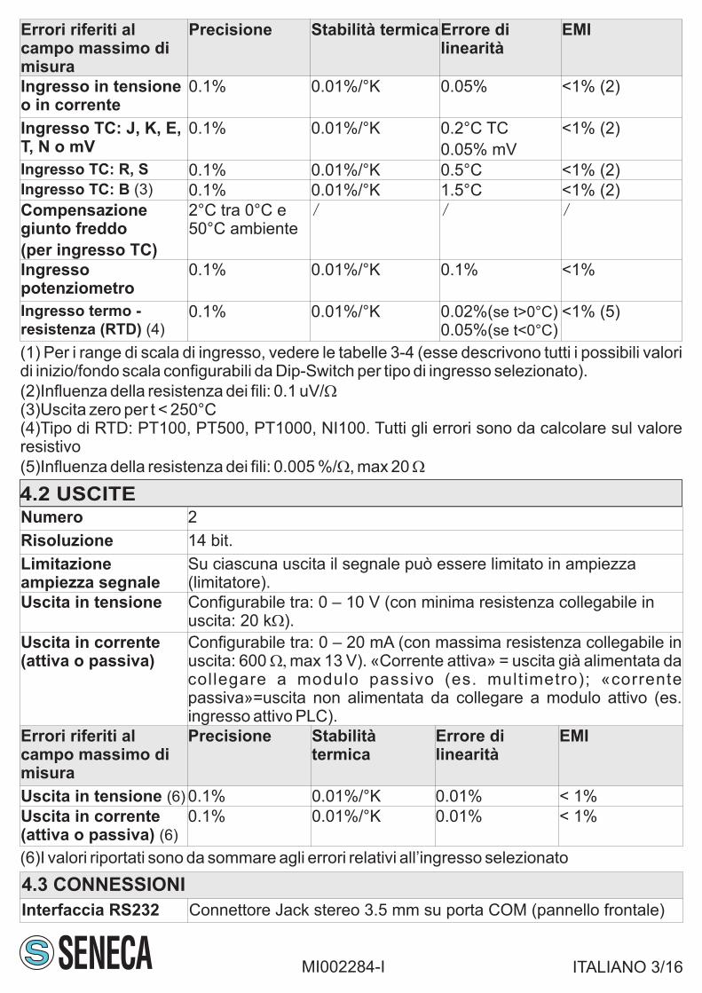
7.3 CONDIZIONE DI DEFAULT
ITALIANO 9/16
La condizione di default per i parametri di comunicazione del modulo è riportata nella tabellaseguente.
Struttura dati di registro pari a 8N1 significa che il registro è strutturato nel seguentemodo: 8 bit di dati, nessun controllo di parità (N), 1 bit di stop.
Comunicazione Struttura dati diregistro
Velocità dicomunicazione
Indirizzo del nodo
R 32S2 8N1 9600 (fisso) 1 (fisso)
MI002284-I
Tipo ingresso CorrenteFiltro su ingresso (segnale acquisito) DisattivatoInizio /Fondo scala ingresso 0 [mA] / 20 [mA]Tipo uscita 1 e uscita 2 Corrente attivaInizio scala uscita 1 e 2 0 [mA]Fondo scala uscita 1 e 2 20 [mA]Limitatore su uscita 1 e 2 DisattivatiEstremo inferiore limitatore dell’uscita 1 e 2 0 [mA]Estremo superiore limitatore dell’uscita 1 e 2 20 [mA]Reiezione alla frequenza di rete/periodo dicampionamento
50 Hz / periodo di campionamento = 20 ms
Compensazione di giunto freddo (peringresso da TC)
Disattivata
Rilevazione errore in ingresso: errore diingresso fuori scala (se ingresso: tensione,corrente, potenziometro); errore di burn-out(se ingresso: TC, RTD)/ Fault value
Disattivata/Fault value = 0 [mA]
La condizione di default per i parametri di configurazione del modulo è riportata nella tabellaseguente (se modalità di configurazione da software).
La condizione di default per i parametri di configurazione del modulo non configurabili con iDip-Switch è riportata nella tabella seguente (se modalità di configurazione da Dip-Switch).
Filtro su ingresso (segnale acquisito) DisattivatoLimitatore su uscita 1 e 2 Disattivati (solo se uscita in corrente 4 –
20mA: limitatore attivato, estremo inferiore-superiore limitatore dell’uscita: 3.6 – 20.4mA)
Reiezione alla frequenza di rete
Periodo di campionamento
Con IN = tensione, corrente, potenziometro,TC, RTD: reiezione = 50Hz,Periodo di campionamento = 20ms(configurabile via software da 5ms a 20ms)
Compensazione di giunto freddo (per ingressoda TC)
AttivataRilevazione errore di ingresso/Fault value Se IN=tensione, corrente, potenziometro:
disattivata; se IN=TC, RTD: attivata, Faultvalue= fondo scala di uscita + 5 %del rangedi scala di uscita
I valori dei parametri di impostazione configurati da Dip-Switch hanno prioritàrispetto i valori memorizzati in memoria EEPROM.

ITALIANO 10/16
Il pannello frontale del modulo comprende 2 LED, lo stato di ciascuno dei quali corrisponde aimportanti condizioni di funzionamento del modulo stesso (figura 4).
LED Stato del LED Significato del LED
PWR Acceso (luce verde) Il modulo è alimentato correttamente
ALARM Acceso (luce gialla) Stato di allarme presente
Spento Stato di allarme assente
MI002284-I
10.1 LAYOUT DEL MODULO E LED DI SEGNALAZIONE
DIMENSIONI DEL MODULO PANNELLO FRONTALE
112 m
m
17,5 mm
100,0 mm
1 2 3
4 5 6
7 8 9
10 11 12
S
PWR
ALARM
Z170REG
COM
4
10. LAYOUT DEL MODULO
Smaltimento dei rifiuti elettrici ed elettronici (applicabile nell’Unione Europea e negli altri paesi conraccolta differenziata). Il simbolo presente sul prodotto o sulla confezione indica che il prodottonon verrà trattato come rifiuto domestico. Sarà invece consegnato al centro di raccolta autorizzatoper il riciclo dei rifiuti elettrici ed elettronici. Assicurandovi che il prodotto venga smaltito in modoadeguato, eviterete un potenziale impatto negativo sull’ambiente e la salute umana, che potrebbeessere causato da una gestione non conforme dello smaltimento del prodotto. Il riciclaggio deimateriali contribuirà alla conservazione delle risorse naturali. Per ricevere ulteriori informazionipiù dettagliate Vi invitiamo a contattare l’ufficio preposto nella Vostra città, il servizio per losmaltimento dei rifiuti o il fornitore da cui avete acquistato il prodotto.
8. DISMISSIONE E SMALTIMENTO
Codice d’ordine Descrizione
Z170REG Duplicatore universale con separazione galvanica
PM001601 Cavo di connessione per comunicazione (da DB9-F)RS232
9. CODICI D’ORDINE

ITALIANO 11/16MI002284-I
Se l’ampiezza del segnale di ingresso IN è compresa tra inizio scala ingresso e fondo scalaingresso, l’uscita è direttamente proporzionale all’ingresso.Se l’ampiezza del segnale di ingresso IN supera l’intervallo [inizio scala ingresso-2.5% delrange di scala, fondo scala ingresso+2.5% del range di scala], il LED ALARM commuta daspento ad acceso e il software segnala errore di ingresso presente.Se l’ampiezza del segnale di ingresso IN diminuisce entro l’intervallo [inizio scala ingresso-2.5% del range di scala, fondo scala ingresso+2.5% del range di scala], il LED ALARMcommuta da acceso a spento e il software segnala errore di ingresso assente.
Se l’ampiezza del segnale di ingresso IN supera anche i limiti hardware del modulo (vedere latabella seguente), il software segnala errore di fail presente.
La condizione «Stato di allarme presente» corrisponde alla presenza di almeno uno tra glierrori di seguito elencati:Tipo di errore Descrizione Tipo di ingresso
interessato
Errore di ingresso L’ampiezza del segnale acquisito in ingresso èinferiore(superiore) al valore di inizio scala(fondo scala) di ingresso oppure il sensore iningresso al modulo è danneggiato (TC, RTD)
Tensione, corrente,potenziometro,termocoppia,termoresistenza
Errore di perditadati in memoriaEEPROM
/ Tutti
Errore diacquisizionetemperatura iningresso
Il sensore di giunto freddo interno al modulo èdanneggiato
Termocoppia
-2.5% +2.5%
Inizioscalaingresso
Fondoscala
ingressoIN IN
-2.5% +2.5%
IN IN
LED ALARMspento acceso
LED ALARMacceso spento
Range di scala
Range di scala
Inizioscalaingresso
Fondoscala
ingresso

ITALIANO 12/16MI002284-I
Tipo di ingresso Limiti hardware del modulo
Tensione 0V; 10.5V
Corrente 0mA; 21mA
Potenziometro 0; 100%
Termocoppia
mV
Se TC J: -210°C; 1200°C. Se TC K: -270°C; 1370°C. Se TC R: -50°C;1760°C. Se TC S: -50°C;1760°C. Se TC T: -270°C; 400°C. SeTC B: 0;1820°C. Se TC E: -270°C; 1000°C. Se TC N: -270°C; 1300°CSe mV: -10 mV; 70 mV.
Termoresistenza Se RTD=NI100: -60°C; 250°CSe RTD=PT100, RTD=PT500, RTD=PT1000: -200°C; 600°C
Se il LED ALARM è acceso (errore di ingresso presente o errore di fail presente) e ladiagnostica su ingresso è attivata, il modulo scrive nelle uscite il valore Fault value.

ITALIANO 13/16MI002284-I
10.2 SCHEMA A BLOCCHI DEL MODULO
Blocco Significato del blocco (figura 5)
FILTRO 0-19 Filtro a 20 livelli sul segnale acquisito in ingressoA/A ConvertitoreAnalogico/AnalogicoLIMITATORE Limitatore dell’ampiezza del segnale in uscita
5
3
5
6
2
1
4
19 28 V– A
10 40 V– C
LIMITATORE
11
10
12
AA
9
7
8P
OT
/RT
DT
CT
EN
SIO
NE
IN
FILTRO0-19
POWERSUPPLY
OU
T1
US
CIT
E
TE
NS
ION
EC
OR
RE
NT
E
OU
T2
++
--
US
CE
NT
EU
SC
EN
TE
EN
TR
AN
TE
EN
TR
AN
TE
ING
RE
SS
O
Modulo
attiv
o (
mA
)
Modulo
pass
ivo
(mA
)
LIMITATORE

ITALIANO 14/16MI002284-I
Questa pagina è stata intenzionalmente lasciata vuota.

ITALIANO 15/16MI002284-I
Questa pagina è stata intenzionalmente lasciata vuota.

ITALIANO 16/16MI002284-I
Questa pagina è stata intenzionalmente lasciata vuota.

ENGLISH 1/16MI002284-E
Analog and universal
Setting by Dip-Switches
IN, OUT1,OUT2, powersupply are isolated (1500V )~
This document is property of SENECA srl. Duplication and reproduction of its are forbidden (t partial), if not authorized.houghContents of present documentation refers to products and technologies described in it. Though we strive for reach perfectioncontinually, all technical data contained in this document may be modified or added due to technical and commercial needs; it’simpossible eliminate mismatches and discordances completely. Contents of present documentation is anyhow subjected toperiodical revision. I don’t hesitate to contact our structure or to write us to e-mail addresses as abovef you have any questionsmentioned.
Chapter index Page
1. Identification data 12. Preliminary warnings 23. Description and characteristics3.1 Module description3.2 General characteristics and features
2
4. Technical specifications4.1 Inputs
4.2 Outputs
4.3 Connections
4.4 1500 V insulations~
4.5 Power supply
4.6 Module case
4.7 Environmental conditions
4.8 Standards
2
5. Preliminary instructions for use 56. Electrical connections6.1 Safety measures before use
6.2 RS232 serial interface
6.3 Connections
5
7. Parameters for use7.1 Setting parameters
7.2 Dip - Switch tables
7.3 Default configuration
6
8. Decommissioning and disposal 99. Purchase order code 910. Module layout10.1 Module layout and signalling LEDs
10.2 Block diagram
10
IN, OUT1,OUT2 are:
SENECA s.r.l.Via Austria, 26 – 35127 – PADOVA – ITALY
Tel. +39.049.8705355 – 8705359 Fax. +39.049.8706287
Internet site: Technical assistance:www.seneca.it [email protected]
Commercial reference: [email protected]
USER MANUAL Z Line
Z170REGUniversal converter module
with galvanic insulationbetween 2 analog outputs
EN

3. DESCRIPTION AND CHARACTERISTICS
3.1 MODULE DESCRIPTION
The Z170REG module acquires 1 universal input signal and converts it to an analog format,sent through 2 universal output signals (regardless and isolated with each other).
2. PRELIMINARY WARNINGS
3.2 GENERAL CHARACTERISTICS AND FEATURES
- It’s possible to choose if the input is: voltage type, current type, potentiometer type,thermocouple (TC) type, RTD (Resistance Temperature Detector) type.- It’s possible to choose if each output is: voltage type, active/passive current type.- 1500 V insulation between: input, power supply, output 1 and output 2 (figure 1).~
- It’s possible to power the sensor if input is in current type modality (max17V).- It’s possible to configure by Dip-Switch or by software (available at www.seneca.it)modality: input-type, outputs-type, start / end scale of each selected input and outputs-type- It’s possible to configure by software: input filter, rejection, burn-out, etc..
4.1 INPUTS
4. TECHNICAL SPECIFICATIONS
Number 1
Resolution 14 bits
Sampling time Configurable between: 16.66 ms (rejection to 60 Hz) or 20 ms (rejection to 50 Hz)
Filter Level configurable between: 0(no filter is applied) – 19
Response time Sampling time +6 ms
Voltage-type
Input (1)
Scale span configurable: from 0 to 10V . Input impedance:120 k~ W.�
Input automatic out of range detection.
Current-type
Input (passive
module / active
module) (1)
Scale span configurable: from 0 mA to 20 mA. Internal shunt: 50 It’s possible to�W.
power the sensor by: itself (passive module) or by module (active module using #7
screw terminal, max 25 mA to max 17 V, short-circuit protected).
Input automatic out of range detection.
Potentiometer
type Input (1)
Scale span configurable: from 1 % to 100 %.
Potentiometer input value from 1 k to 100 k (a R= 330 parallel circuit must beW W �W�
added). Energising current: 1 mA. Input impedance: > 5 MW.
Input automatic out of range detection.
Thermocouple
type Input (1)
For TC type: J, K, R, S, T, B, E, N. Input impedance: > 5 MW.
Input automatic burn-out detection.
Range from –10 mV to +70 mV. Input impedance: > 5 MW.
RTD-type
Input (1)
For RTD type: P 00, P 500, P 1000, N 100. Resistance measureT T T I1(for 2,3,4-wires connection) and wire-resistance measure. Excitation current: 1.1 mA(PT100) and 0.11 mA(PT1000, PT500). Input automatic burn-out detection.
ENGLISH 2/16MI002284-E
Before carrying out any operation it’s mandatory to read all the content of this userManual. Only electrical-skilled technicians can use the module described in this userManual.
No warranty is guaranteed in connection with faults resulting from improper use, frommodifications or repairs carried out by anufacturer-unauthorised personnel on theMmodule, or if the content of this user Manual is not followed.
Only the M repair the module or to replace damagedanufacturer is authorized tocomponents.

(6)These values have to be added to the errors of the selected input.
4.2 OUTPUTS
Number 2
Resolution 14 bits
Signal-amplitudelimiting
The output signal can be amplitude-limited by a «limiter» (for eachoutput)
Voltage-type OUT Configurable between: 0 – 10 V (minimum resistence that can beconnected: 20 k )W
Current-type OUT(active or passive)
Configurable between: 0 – 20 mA (maximum resistence that can beconnected: 600 max13 V ). «Active current»=the output: alreadyW,� ~
powered on, needs to be connected to the passive module (es.multimeter); «passive current»=the output: powered off, needs to beconnected to the active module (es. active input of a PLC)
Errors related tomax measuringrange
Accuracy Thermalstability
Linearity error EMI
Voltage-type OUT(6) 0.1% 0.01%/°K 0.01% < 1%
Current-type OUT(active or passive) (6)
0.1% 0.01%/°K 0.01% < 1%
(1)For the input scale ranges, see tables 3 – 4 (description of all start/end-scale settings byDip-Swithes modality for each selected input type)
(2)Influence of wire resistance: 0.1 uV/W(3)Output zero if t < 250°C(4)For RTD type: P 00, P 500, P 1000, N 100. All the errors have to be calculated withT T T I1reference to resistive value
(5)Influence of wire resistance: 0.005 %/ , max 20W W
Errors related to maxmeasuring range
Accuracy Thermalstability
Linearity error EMI
Voltage or current-input type
0.1% 0.01%/°K 0.05% <1% (2)
TC-input type: J, K,E, T, N
0.1% 0.01%/°K 0.2°C <1% (2)
TC-input type: R, S 0.1% 0.01%/°K 0.5°C <1% (2)
TC-input type: B (3) 0.1% 0.01%/°K 1.5°C <1% (2)
Cold junctioncompensation
(for TC-input type)
2°C between
0-50°C
/ / /
POT-input type 0.1% 0.01%/°K 0.1% <1%
RTD-input type (4) 0.1% 0.01%/°K 0.02%( )if t>0°C <1% (5)
ENGLISH 3/16MI002284-E
4.3 CONNECTIONS
RS232 interface Jack stereo 3.5mm connector:plugs into COMport (front-side panel)

4.4 1500 V INSULATIONS~
4.5 POWER SUPPLY
Supply voltage 10 – 40 V or 19 – 28 V (50Hz-60Hz), between 2 –3 screw~ ~
terminals
Power-supply unit Class 2
Power consumption Min: 0.5 W; Max: 2 W
The isolation voltage between:- power supply- analog input- analog output 1- analog output 2is (figure 1).1500 V~
ENGLISH 4/16MI002284-E
Install a 2.5A-Max rated fuse near the module.
4.6 MODULE CASE
Box PBT, black
Dimensions Width W = 100 mm, Height H = 112 mm, Depth D = 17.5 mm
Terminal board Removable 3-way screw terminals: pitch 5.08 mm, section 2.5 mm2
Protection class IP20 (International Protection)
4.6 ENVIRONMENTAL CONDITIONS
Operatingtemperature
-10°C – +60°C (UL: -10°C – +60°C)
Humidity 30 – 90% to 40°C not condensing (during operation)
Max enviromentpollution degree
2 (during operation)
Storage temperature -20°C – +85°C
The module complies with the following standards:-EN 61000-6-4 (electromagnetic emission, in industrial enviroment)-EN 61000-6-2 (electromagnetic immunity, in industrial enviroment)-EN 61010-1(safety).One Max 2.5Afuse must be installed near the module.
4.7 STANDARDS
IN
AC , DC~ ~
OUT-V
OUT-mA
1
OUT 2
IN-V
IN-m
A
IN-P
OT
IN-T
C
IN-R
TD
PowerSupply
RS 232
OUT-V
OUT-mA
OUT 1

If the modules are installed side by side, in theseparate them by at least 5 mmfollowing cases:-the operating temperature exceeds 45°C and at least one of the severe operatingconditions exists; or-the operating temperature exceeds 35°C and at least two of the severe operatingconditions exist.
6.2 RS232 SERIAL INTERFACE
ENGLISH 5/16MI002284-E
5. PRELIMINARY INSTRUCTIONS FOR USE
It is forbidden to place anything that could obstructs the ventilation slits.It is forbidden to install the module near heat sources.
The module is designed to be installed on DIN 46277 rail in vertical position.
6. ELECTRICAL CONNECTIONS
6.1 SAFETY MEASURES BEFORE USE
To satisfy the electromagnetic compliance requirements:-use shielded cables for signal transmittion;-connect the shield to a earth wire used specifically for instrumentation;-insert space between these shielded cables and other cables used for powerappliances (inverters, motors, induction ovens, etc...).
Power off the module before connecting: RS232 serial interface, input,outputs.
The module is designed to data interchange according to the ModBUS protocol rules,implemented by RS232 serial interface. If the module is connected to RS232 interface-port ,its ( ) communication parameters have a register data structure equal to 8N1.unchangeable
The module has a Jack stereo connector in order to connect its to RS232-buscommunication (figure 2).
2
GND Tx Rx
6.3 CONNECTIONS
Power on the module with <! 40 V or < 28 V voltage supply. These upper~ ~
limits must not be exceeded to avoid serious damage to the module.
POWER SUPPLY 2
3
19 – 28 V~10 – 40 V~2 W Max
Severe operating condions are as follow:-high power supply voltage: >30 V or > 26 V .~ ~
-Module power supply the sensor at input;-Output used as current generator (connected to a passive module)

7. PARAMETERS FOR USE
7.1 SETTING PARAMETERS
ENGLISH 6/16MI002284-E
Parameters Modality Options
Input type Software/
DipSwitch
Voltage, Current, Potentiometer,TC,RTD; if Dip-Switch modality then see table 1
mV Input type Software mV Voltage configurable only by software
Input filter Software Activated/Disactivated; if activated: from 0 to 19
Input start/end scale Software/
DipSwitch
If Dip-Switch modality, see tables 3 – 4
Output 1, 2 type Software/
DipSwitch
Voltage, Current (active,passive); if Dip-Switchmodality then see table 2
Output 1,2 start/endscale
Software/DipSwitch
If Dip-Switch modality, see table 2
Output 1,2 limiters Software Activated/Disactivated; if deactivated, output limitsare: if OUT=voltage, [0 V;10.5 V]; if OUT=current,[0m A; 21 mA]
Network frequencyrejection/sampling time
Software No rejection: 5 ms («Fast»); 50 Hz-rejection: 20 ms;60 Hz-rejection: 16.66 ms
(for TC-type input) Coldjunction compensation
Software Activated/Disactivated
Detection of input fail:over-scala input erroror burn-out error
Software Activated/Disactivated (for OUT1 and OUT2); ifactivated: the two «Fault values» (for each output)have to be configured
3-wire RTD
12
10
9
8
4-wire RTD
12
10
9
8
INPUTS (SENSORS «S» CONNECTION) OUTPUT 1 OUTPUT 2
11(-)
7(+)
Voltage
10
9+
10
12
9
POT8
mV/TC
10
12+
RP
10(-)
11(+)
Passive module Active module 2-wire RTD
12
10
9
8
With R = 330 W
(it needs to beadded externally),
P=1 k -100 kW W
The sensorpower the loop(in mA)
The modulepower the loop(in mA)
5 16 4
+ +
V V
Voltage
mA mA+ +
++ VextVext
mA mA
Current (Z170REG passive)
Current (Z170REG active)
+ +
3
+ +- -
- -+ +
+ +

7.2 DIP-SWITCH TABLES
ENGLISH 7/16MI002284-E
In the following tables: box without circle means Dip-Switch=0 (OFF state); box withcircle means Dip-Switch=1 (ON state); box with X means indifferent (ON state orOFF state are both usable)
1 2 3 4 5 Meaning
Voltage-type input
Current-type input
Potentiometer-type input (POT)
Thermocouple J-type input (TC J)
Thermocouple K-type input (TC K)
Thermocouple R-type input (TC R)
Thermocouple S-type input (TC S)
Thermocouple T-type input (TC T)
Thermocouple B-type input (TC B)
Thermocouple E-type input (TC E)
Thermocouple N-type input (TC N)
P 100 (RTD)-type input: 2 wires connectionT
P 100 (RTD)-type input: 3 wires connectionT
P 100 (RTD)-type input: 4 wires connectionT
NI100 (RTD)-type input: 2 wires connection
Ni100 (RTD)-type input: 3 wires connection
Ni100 (RTD)-type input: 4 wires connection
P 500 (RTD)-type input: 2 wires connectionT
P 500 (RTD)-type input: 3 wires connectionT
P 500 (RTD)-type input: 4 wires connectionT
P 1000 (RTD)-type input: 2 wires connectionT
P 1000 (RTD)-type input: 3 wires connectionT
P 1000 (RTD)-type input: 4 wires connectionT
Table 1 - INPUT TYPE (Dip-Switches SW1: TYPE INPUT)
1 2 3 4 5 Meaning
X X X Voltage-type output 1: 0 – 10 V
X X X Voltage-type output 1: 0 – 5 V
X X X Current-type output 1: 0 – 20 mA
X X X Current–type output 1: 4 – 20 mA
X X X Voltage–type output 2: 0 – 10 V
X X Voltage–type output 2: 0 – 5 V
X X Current–type output 2: 0 – 20 mA
X X Current–type output 2: 4 – 20 mA
X X X X If current-type output: active current
X X X X If current-type output: passive current
Table 2 - OUTPUT 1 AND 2 TYPE (Dip-Switches SW2: TYPE OUTPUT)
The module acquires the parameters through Dip-Switches, if the module Dip-Switches are configurated as shown in the following tables 1, 2, 3, 4. Forwhatever other Dip-Switches configuration,ALL parameters are acquired frommemory, regardless of the Dip-Switches configuration.

S 2W Table 4 - END-SCALE VALUES FOR SELECTED INPUT TYPE
6 7 8 TC B TC E TC N P 100T N 100I P 500T P 1000T
500 °C 50 °C 200 °C 50 °C 20 °C 0 °C 0 °C
600 °C 100 °C 400 °C 100 °C 40 °C 50 °C 50 °C
800 °C 200 °C 600 °C 200 °C 50 °C 100 °C 100 °C
1000 °C 300 °C 800 °C 300 °C 80 °C 150 °C 150 °C
1200 °C 400 °C 1000 °C 400 °C 100 °C 200 °C 200 °C
1500 °C 600 °C 1200 °C 500 °C 150 °C 300 °C 300 °C
1800 °C 800 °C 1300 °C 600 °C 200 °C 400 °C 400 °C
S 2W Table 4 - END-SCALE VALUES FOR SELECTED INPUT TYPE
6 7 8 Voltage Current POT TC J TC K TC R TC S TC T
0.5 V 1 mA 40% 100 °C 200 °C 400 °C 400 °C 50 °C
1 V 2 mA 50% 200 °C 400 °C 600 °C 600 °C 100 °C
2 V 3 mA 60% 300 °C 600 °C 800 °C 800 °C 150 °C
3 V 4 mA 70% 400 °C 800 °C 1000 °C 1000 °C 200 °C
4 V 5 mA 80% 500 °C 1000 °C 1200 °C 1200 °C 250 °C
5 V 10 mA 90% 800 °C 1200 °C 1400 °C 1400 °C 300 °C
10 V 20 mA 100% 1000 °C 1300 °C 1750 °C 1750 °C 400 °C
S 1W Table 3 - START-SCALE VALUES FOR SELECTED INPUT TYPE
6 7 8 TC B (*) TC E TC N P 100T N 100I P 500T P 1000T
0 °C -200 °C -200 °C -200 °C -50 °C -200 °C -200 °C
500 °C -100 °C -100 °C -100 °C -30 °C -100 °C -100 °C
600 °C 0 °C 0 °C -50 °C -20 °C -50 °C -50 °C
700 °C 100 °C 100 °C 0 °C 0 °C 0 °C 0 °C
800 °C 150 °C 200 °C 50 °C 20 °C 50 °C 50 °C
1000 °C 200 °C 300 °C 100 °C 30 °C 100 °C 100 °C
1200 °C 400 °C 500 °C 200 °C 50 °C 200 °C 200 °C
S 1W Table 3 - START-SCALE VALUES FOR SELECTED INPUT TYPE
6 7 8 Voltage Current POT TC J TC K TC R TC S TC T
0 V 0 mA 0% -200 °C -200 °C 0 °C 0 °C -200 °C
0.5 V 1 mA 10% -100 °C -100 °C 100 °C 100 °C -100 °C
1 V 2 mA 20% 0 °C 0 °C 200 °C 200 °C -50 °C
2 V 3 mA 30% 100 °C 100 °C 300 °C 300 °C 0 °C
4 V 4 mA 40% 200 °C 200 °C 400 °C 400 °C 50 °C
5 V 5 mA 50% 300 °C 300 °C 600 °C 600 °C 100 °C
10 V 10 mA 60% 500 °C 500 °C 800 °C 800 °C 150 °C
Power off the module before configuring it by Dip-Switches to avoid seriousdamage due to electrostatic discharges.
ENGLISH 8/16MI002284-E
(*) Output zero if t < 250°C

LED LED state Meaning
PWR Turned on (green light) The module power is on
ALARM Turned on (yellow light) There is an alarm
Turned off There isn’t an alarm
10.1 MODULE LAYOUT AND SIGNALLING LEDSMODULE DIMENSIONS FRONT-SIDE PANEL
112 m
m
17,5 mm
100,0 mm
1 2 3
4 5 6
7 8 9
10 11 12
S
PWR
ALARM
Z170REG
COM
4
10. MODULE LAYOUT
ENGLISH 10/16MI002284-E
In the front-side panel there are 2 LEDs and their state refers to important operating conditionsof the module (figure 4).
Order code Specification
Z170REG DC universal duplicator / isolator
PM001601 Programming cable
8. DECOMMISSIONING AND DISPOSALDisposal of Electrical & Electronic Equipment (Applicable throughout the European Union andother European countries with separate collections programs). This symbol, found on yourproduct or on its packaging, indicates that this product should not be treated as household wastewhen you wish to dispose of it. Instead, it should be handed over to an applicable collection pointfor the recycling of electrical & electronic equipment. By ensuring this product is disposed ofcorrectly, you will help prevent potential negative consequences to the environment and humanhealth, which could otherwise be caused by inappropriate disposal of this product. The recycling ofmaterials will help to conserve natural resources. For more detailed information about therecycling of the product, please contact your local city office, waste disposal service of the retailstore where you purchased this product.
9. PURCHASE ORDER CODE

Input type Current
Input filter Deactivated
Input Start-scale/End-scale 0 [mA]/20 [mA]
Output 1 type/Output 2 type Active current
Output 1 and 2 Start-scale 0 [mA]
Output 1 and 2 End-scale 20 [mA]
Output 1 and 2 Limiters Deactivated
Limit inferior for Output 1 and 2 Limiters 0 [mA]
Limit superior for Output 1 and 2 Limiters 20 [mA]
Network frequency Rejection/sampling Deactivated/sampling time = 5 ms
Cold Junction compensation (for TC-typeinput)
Deactivated
Detection of input fail: over-scala input error(if voltage, current, potentiometer-type) orburn-out error(if TC, RTD-type)/Fault values
Deactivated/Fault values = 0 [mA]
Active current means output already powered on, needs to be connected to thepassive module.
ENGLISH 9/16MI002284-E
7.4 DEFAULT CONFIGURATION
The default configuration for the communication parameters is shown in the following table.
Data structure of register equal to 8N1 means that the register is structured asfollows: 8 data bits, no parity control (N), 1 stop bit.
Communication Data structure ofregister
Baud-rate Address of node
RS232 8N1 9600 ( )unchangeable 1 ( )unchangeable
The default configuration for the setting parameters is shown in the following table (ifconfiguration modality by software).
The default configuration for the setting parameters is shown in the following table (ifconfiguration modality by Dip-Switches).
Input filter Deactivated
Output 1 and 2 Limiters Deactivated (only if current-type output 4 – 20mA: limiter is activated; limit inferior-superiorof output:3.6 – 20.4 mA)
Network frequency Rejection/sampling If IN=voltage, current, potentiometer: norejection, sampling time = 5ms; if IN=TC, RTD:rejection = 50Hz, sampling time = 20ms
Cold Junction compensation (for TC-typeinput)
Activated
Detection of input fail: over-scala input error(if voltage, current, potentiometer-type) orburn-out error(if TC, RTD-type)/Fault values
If IN=voltage, current, potentiometer:deactivated; if IN=TC, RTD: activated, Faultvalues=output end scale +5 % of output scalarange
The values of setting parameters configurated by Dip-Switches modality has priorityover the values stored in memory EEPROM.

ENGLISH 11/16MI002284-E
If the amplitude of the acquired input signal IN is between the input start scale and input endscale, the output is directly proportional to the input.If the amplitude of the acquired input signal IN exceeds the interval [input start scale - 2.5 % ofinput scala range, input end scale + 2.5 % of input scala range], the LED ALARM switchesfrom turned off to turned on and the software signals that there is a input error.If the amplitude of the acquired input signal IN decreases into the interval [input start scale-2.5 % of input scala range, input end scale + 2.5 %of input scala range], the LED ALARM
switches from turned on to turned off and the software signals that there isn’t a input error.
If the amplitude of the acquired input signal IN exceeds the hardware module limits too (seethe following table), the software will also signal that there is a error fail.
If there is an alarm, the module has at least one of the following errors:
Tipo di errore Descrizione Tipo di ingressointeressato
Inputtemperature-acquired error
The cold-junction internal sensor is damaged Thermocouple
Input error The amplitude of the acquired input signal isless than (greater than) the input start scale(end scale) or the TC/RTD sensor is damaged
Voltage, current,potentiometer,thermocouple,thermoresistance
Loss of data error / All
-2.5% +2.5%
Inputscalarange
Inputend
scale
IN IN
-2.5% +2.5%
IN IN
LED ALARMturned off turned onScala range
Scala range
Inputstartscale
Inputend
scale
LED ALARMturned on turned off

ENGLISH 12/16MI002284-E
If the LED ALARM is turned on (there is a input error or there is a fail error) and if detection ofinput fail is activated, the module overwrites the outputs with «Fault values».
Voltage 0 V; 10.5 V
Current 0 mA; 21 mA
Potentiometer 0; 100 %
Thermocouple
mV
If TC J: -210°C; 1200°C. If TC K: -270°C; 1370°C. If TC R: -50°C;1760°C. If TC S: -50°C;1760°C.If TC T: -270°C; 400°C. If TC B:0;1820°C. If TC E: -270°C; 1000°C. If TC N: -270°C; 1300°CIF mV: -10mV; 70mV.
Thermoresistance If RTD=NI100: -60°C; 250°CIf RTD=PT100, RTD=PT500, RTD=PT1000: -200°C; 600°C
Input type Module hardware limits

ENGLISH 13/16MI002284-E
This page intentionally left blank.10.2 BLOCK DIAGRAM
Block Block meaning (figure 5)
FILTER (0-19) 20-levels filter, which an input-acquired signal is applied
A/A Analog toAnalog Converter
LIMITER 1, 2 Signal-amplitude limiters for Output 1, 2
5
3
5
6
2
1
4
19 – 28 V~10 – 40 V~
LIMITER 1
LIMITER 2
11
10
12
AA
9
7
8
PO
T/R
TD
TC
VO
LTA
GE
IN
FILTER(0-19)
POWERSUPPLY
OU
T1
OU
TP
UT
S
VO
LTA
GE
CU
RR
EN
T
OU
T2
++
--
OU
TW
AR
DS
OU
TW
AR
DS
INW
AR
DS
INW
AR
DS
INP
UT
Active m
odule
(mA
)
Passiv
e m
odule
(mA
)

ENGLISH 14/16MI002284-E
This page intentionally left blank.

ENGLISH 15/16MI002284-E
This page intentionally left blank.

ENGLISH 16/16MI002284-E
This page intentionally left blank.

FRANÇAIS 1/16MI002284-F
Ce document est la propriété de SENECA srl. Il est interdit de le copier ou de le reproduire sans autorisation. Le contenu de laprésente documentation correspond aux produits et aux technologies décrites. Les données reportées pourront être modifiées oucomplétées pour des exigences techniques et/ou commerciales.
Sommaire Pag.1. Données d'identification2. Avertissements préliminaires 23. Description et caractéristiques3.1 Description du module3.2 Caractéristiques générales
2
4. Caractéristiques techniques4.1 Entrées4.2 Sorties4.3 Connexions4.4 Isolations à 1500 V~4.5 Alimentation4.6 Boîtier du module4.7 Conditions ambiantes4.8 Normes
2
5. Instructions préliminaires avant l'utilisation 56. Branchements électriques6.1 Mesures de sécurité avant l'utilisation6.2 Interface série RS2326.3 Branchements
5
7. Paramètres pour l'utilisation7.1 Paramètres de configuration7.2 Tableau des commutateurs7.3 Condition par défaut
6
8. Démolition et élimination 99. Codes d'ordre 910. Layout du module10.1 Layout du module et DEL de signalisation10.2 Schéma fonctionnel du module
10 Analogiques et universels
Configurables avec lescommutateurs
I N , O U T 1 , O U T 2 ,al imentation : séparésgalvaniquement
IN, OUT1, OUT2:
SENECA s.r.l.Via Austria, 26 – 35127 – PADOVA – ITALYTel. +39.049.8705355 – 8705359 Fax. +39.049.8706287Site Internet: Assistance technique:www.seneca.it [email protected]éférence commerciale: [email protected]
MANUEL D'INSTRUCTIONS Serie Z
Z170REGModule convertisseur universel
avec 2 sorties analogiquesséparées galvaniquement
F

3. DESCRIPTION ET CARACTÉRISTIQUES3.1 DESCRIPTION DU MODULE
Le module Z170REG acquiert un signal d'entrée universel et le convertit en format analogique, retransmissur deux sorties universelles indépendantes l'une de l'autre et isolées.
2. AVERTISSEMENTS PRÉLIMINAIRES
FRANÇAIS 2/16MI002284-F
3.2 CARACTÉRISTIQUES GÉNÉRALES-Possibilité de choisir si entrée : en tension, en courant ou à partir du potentiomètre, du thermocouple (TC), dela thermorésistance (RTD)-Possibilité de choisir si chaque sortie est en : tension, courant active/passive-Isolation égale à 1 500 V entre : entrée, alimentation, sortie 1 et sortie 2 (figure 1)~
-Possibilité d'alimenter le capteur si entrée en courant (borne 7, max. 17V )~-Possibilité de configurer ce qui suit à l'aide des commutateurs et du logiciel (disponible sur le sitewww.seneca.it) : type entrée et sorties, début/bas d'échelle pour type entrée et sorties sélectionnés-Possibilité de configurer ce qui suit à l'aide du logiciel: filtre entrée, réjection, burn-out, etc.
4.1 ENTRÉES4. CARACTÉRISTIQUES TECHNIQUES
Numéro 1Résolution 14 bitPérioded'échantillonnage
Configurable entre: 16,66 ms (réjection à 60 Hz) ou 20 ms (réjection à 50 Hz
Filtre Pouvant être activé sur le signal acquis, niveau configurable entre : 0 – 19Temps de réponse Période d'échantillonnage +6 ms.Entrée entension (1)
Plage d'échelle configurable: de 0 V à 10 V . Impédance d'entrée:~
120 k . Relevé automatique si entrée hors échelle.W
Entrée encourant (1)(Module actif /passif en mA)
Plage d'échelle configurable : de 0 mA à 20 mA. Shunt interne : 50 .�W
Alimentation à la boucle du capteur fournie par : le capteur S (module passifen mA) ou par le module (module actif en mA) à travers la borne 7 (max. 25mA à max. 17 V) protégée par un court-circuit Relevé automatique si entréehors échelle.
Entrée à partir dupotentiomètre (1)
Plage d'échelle configurable : de 1% à 100%de 1 k à 100 k (avec R = 330 k en parallèle à ajouter à l'extérieur).W W W
Courant d'excitation: 1 mA. Impédance d'entrée: > 5 M . RelevéW
automatique si entrée hors échelle.Entrée (1)thermocouple(TC)ou mV
Type de TC : J, K, R, S, T, B, E, N. Impédance d'entrée : > 5 M . RelevéW
automatique si burn-out.Gamme de –10 mV à +70 mV. Impédance d'entrée: > 5 MW.
Entrée (1)thermorésistance(RTD)
Type de RTD: Pt100, Pt500, Pt1000, Ni100. Mesure résistance (pour 2,3,4fils) et résistance de fil. Courant excitation: 1,1 mA (PT100) et 0,11 mA(PT1000, PT500). Relevé automatique si burn-out.
Avant de faire une opération quelconque, lire obligatoirement le contenu du présentManuel. Le module ne doit être utilisé que par des techniciens qualifiés dans lesecteur des installations électriques.
La garantie cesse de droit en cas d'usage impropre ou d'altération du module ou desdispositifs fournis par le fabricant, nécessaires au fonctionnement correct, et si lesinstructions contenues dans le présent manuel n'ont pas été suivies.
Seul le fabricant peut réparer le module ou remplacer les composants abîmés.

(6)Les valeurs reportées doivent être sommées aux erreurs relatives à l'entrée sélectionnée
4.2 SORTIESNuméro 2
résolution 14 bit
Limite ampleursignal
Le signal peut être limité en ampleur (limiteur) sur chaque sortie
Sortie en tension Configurable entre : 0 – 10 V (avec résistance minimale à relier à~
la sortie : 20 k )W
Sortie en courant(active ou passive)
Configurable entre : 0 – 20 mA (avec résistance maximale à relier à lasortie : 600 , max. 13V ). « Courant actif »=sortie déjà alimentée àW ~
relier au module passif (ex. multimètre) ; « courant passif »=sortie pasalimentée à relier au module actif (ex. entrée active PLC)
Erreurs se référantau champ maximalde mesure
Précision Stabilitéthermique
Erreur delinéarité
EMI
Sortie en tension (6) 0.1% 0.01%/°K 0.01% < 1%Sortie en courant (activeou passive) (6)
0.1% 0.01%/°K 0.01% < 1%
FRANÇAIS 3/16MI002284-F
4.3 CONNEXIONSinterface RS232 Connecteur Jack stéréo 3,5 mm sur port COM (panneau frontal)
(1) Pour les plages d'échelle d'entrée, voir les tableaux 3-4 (ils décrivent toutes les valeurspossibles de début/bas d'échelle configurables avec le commutateur pour le type d'entréesélectionné).(2) Influence de la résistances des fils : 0,1 uV/ (3) Sortie zéro pour t < 250°C.W
(4) Type de RTD : Pt100, Pt500, Pt1000, Ni100. Toutes les erreurs doivent être calculées surla valeur résistive.(5) Influence de la résistances des fils : 0,005%/ , Max. 20W W
Erreurs se référantau champ maximalde mesure
Précision Stabilitéthermique
Erreur delinéarité
EMI
Entrée encourant/tension
0.1% 0.01%/°K 0.05% <1% (2)
Entrée TC: J, K, E, T,N
0.1% 0.01%/°K 0.2°C <1% (2)
Entrée TC: R, S 0.1% 0.01%/°K 0.5°C <1% (2)Entrée TC: B (3) 0.1% 0.01%/°K 1.5°C <1% (2)compensation jointfroid(Entrée TC)
2°C entre 0°C..50°C
/ / /
Entrée potentiomètre0.1% 0.01%/°K 0.1% <1%
Entrée (RTD) (4) 0.1% 0.01%/°K 0.02%( )t>0°C0.05%( )t<0°C
<1% (5)

FRANÇAIS 4/16MI002284-F
4.4 ISOLATIONS À 1500 V~
4.5ALIMENTATIONTension à fournir aumodule
10 – 40 V ou 19 – 28 V (50 Hz – 60 Hz), à travers les bornes 2 – 3~ ~
Dispositif d'alimentation Classe 2Absorption dumodule
min: 0.5 W; Max: 2 W
Utiliser le module avec des conducteurs en cuivre. Le transformateur d'alimentation doitremplir les conditions décrites dans la norme EN60742 (Transformateurs d'isolation ettransformateurs de sécurité). Si le module est alimenté avec un dispositif d'alimentation isolélimité en tension/en courant, installer un fusible ayant un débit Max. de 2,5A.
La tension d'isolation entre :-alimentation-entrée analogique-sortie analogique 1-sortie analogique 2est égale à 1500 V (figure 1).~
4.7 CONDITIONS AMBIANTESTempérature defonctionnement
-10°C – +60°C (UL: -10°C – +60°C)
humidité 30 – 90 % a 40°C non condensante
Degré de protection 2 (pollution ambiante maximale durant le fonctionnement)
temperature destockage
-20°C – +85°C
4.6 BOÎTIER DU MODULEBoîtier PBT, colore nero
Dimensions Largeur L=100 mm ; hauteur H=112 mm ; profondeur W=17,5 mm
Bornier Extractible à 3 voies: pas des bornes 5,08 mm, section de la borne:2,5 mm²
Degré de protection IP20
L'instrument est conforme aux normes suivantes-EN 61000-6-4 (émission électromagnétique, milieu industriel)-EN 61000-6-2(immunité électromagnétique, milieu industriel)-EN 61010-1(sécurité).
4.8 NORMES
IN
AC , DC~ ~
OUT-VOUT-mA
1
OUT 2
IN-V
IN-m
AIN
-PO
TIN
-TC
IN-R
TD
PowerSupply
RS 232
OUT-VOUT-mA
OUT 1

ITALIANO 5/16MI0022824-F
5. INSTRUCTIONS PRÉLIMINAIRES AVANT L'UTILISATIONLe module a été conçu pour être monté à la verticale sur un guide DIN 46277.
Il est interdit de boucher les fentes d'aération avec un objet quelconque.Il est interdit d'installer le module à proximité d'appareils qui dégagent de la chaleur.
6. BRANCHEMENTS ÉLECTRIQUES
6.1 MESURES DE SÉCURITÉ AVANT L'UTILISATIONCouper l'alimentation du module avant de brancher : interface série RS232,entrées, sorties.
Espacer d'au moins 5 mm Z170REG des modules adjacents si Z170REG est destinéà fonctionner dans un des cas énumérés ci-dessous :-température de fonctionnement supérieure à 45°C et avec au moins une conditionde fonctionnement difficile ;-température de fonctionnement supérieure à 35°C et avec au moins deuxconditions de fonctionnement difficiles ;
Les « Conditions de fonctionnement difficiles » sont les suivantes :-tension d'alimentation supérieure à : 30 V (si continue), 26 V (si alternée) ;~ ~
-le module alimente le capteur à l'entrée ;-configuration de la sortie en courant active (sortie déjà alimentée à relier au modulepassif).
Pour remplir les conditions d'immunité électromagnétique :-utiliser des câbles blindés pour les signaux ;-brancher le blindage à une terre spécifique pour l'instrument ;-espacer les câbles blindés des autres câbles utilisés pour les installations depuissance (inverseurs, moteurs, fours à induction, etc.).
Le module est conçu pour échanger des données selon les modes définis par le protocoleModBUS et implémentées par l'interface série RS232. Si le module est branché à l'interfaceRS232, ses paramètres de communication (fixes) ont une structure des donnéesd'enregistrement de type 8N1. Le module est équipé d'un connecteur Jack stéréo qui permetde le brancher au bus de communication (figure 2).
6.2 INTERFACE SÉRIE RS232
2
GND Tx Rx
6.3 BRANCHEMENTS
S'assurer que le module n'est pas alimenté avec une tension d'alimentationsupérieure à : 40 V (si continue), 28 V (si alternée) pour ne pas l'abîmer.~ ~
ALIMENTATION 2
3
19 – 28 V~10 – 40 V~2 W Max

FRANÇAIS 6/16MI002284-F
7. PARAMÈTRES POUR L'UTILISATION
7.1 PARAMÈTRES DE CONFIGURATIONParamètres modes options pouvant être sélectionnéesType d'entrée Software/
DipSwitchTension-Courant-Potentiomètre-TC-RTD ; simode commutateurs, voir le tableau 1
Type entrée mV Software Tension mV configurable uniquement par logicielFiltre sur entrée Software Activé/Désactivé ; si activé : de 0 à 19Début/bas d'échelle entrée Software/
DipSwitchSi mode commutateurs, voir les tableaux 3 – 4
Type de sortie 1 et 2 Software/DipSwitch
Tension - Courant (active et passive) ; si modecommutateurs, voir le tableau 2
Software/DipSwitch
Réjection à la fréquence der é s e a u e t p é r i o d ed'échantillonnage
Software Sans réjection : 5 ms (Fast); réjection à 50 Hz:20 ms; réjection à 60 Hz: 16,66 ms
Limiteur sur sortie 1 et 2 Software Activé/désactivé (chacun). Si désactivé, leslimites sont: si OUT = tension, [0 V ;10,5 V] ; siOUT = courant, [0 mA; 21 mA]
Compensation de joint froid(pour entrée depuis le TC)
Software Activé/Désactivé
Relevé erreur d'entrée : erreurd'entrée hors échelle ou burnout
Software Activé/Désactivé (pour OUT1 et OUT2) ; siactivé : configurer les deux « Fault value » (pourchaque sortie)
RTD 3 fils
1210
98
RTD 4 fils
1210
98
ENTRÉES (BRANCHEMENTS CAPTEURS S) SORTIE 1 SORTIE 2
11(-)
7(+)
Tensiòn
10
9+
10129
POT8
mV/TC
10
12+
R
PAvec R = 330 W
(à ajouterà l'extérieur),P=1 k -100 kW W
10(-)
11(+)
L'alimentation à laboucle (mA) est fourniepar le capteur
L'alimentation à laboucle (mA) est fourniepar le module
Module actif Module passif RTD 2 fils
1210
98
Début/bas d'échelle sortie1 et 2
Si mode commutateurs, voir letableau 2
5 16 4
+ +
V V
Tension
mA mA+ +
++ VextVext
mA mA
Courant (Z170REG passive)
Courant (Z170REG active)
+ +
- -+ +
+ +- -
+ +

FRANÇAIS 7/16
Dans les tableaux suivants : la case sans boule signifie commutateur sur 0 (état OFF); la case avec boule signifie commutateur sur 1 (état ON), la case avec X signifieindifférent (état ON ou état OFF )sont à la fois utilisable
MI002284-F
7.2 TABLEAU DES COMMUTATEURS
1 2 3 4 5 SignificationEntrée en tensionEntrée en courantEntrée à partir du potentiomètre (POT)Entrée à partir du thermocouple J (TC J)Entrée à partir du thermocouple K (TC K)Entrée à partir du thermocouple R (TC R)Entrée à partir du thermocouple S (TC S)Entrée à partir du thermocouple T (TC T)Entrée à partir du thermocouple B (TC B)Entrée à partir du thermocouple E (TC E)Entrée à partir du thermocouple N (TC N)Entrée à partir de la thermorésistance (RTD) Pt100 : 2 filsEntrée à partir de la thermorésistance (RTD) Pt100 : 3 filsEntrée à partir de la thermorésistance (RTD) Pt100 : 4 filsEntrée à partir de la thermorésistance (RTD) Ni100 : 2 filsEntrée à partir de la thermorésistance (RTD) Ni100 : 3 filsEntrée à partir de la thermorésistance (RTD) Ni100 : 4 filsEntrée à partir de la thermorésistance (RTD) Pt500 : 2 filsEntrée à partir de la thermorésistance (RTD) Pt500 : 3 filsEntrée à partir de la thermorésistance (RTD) Pt500 : 4 filsEntrée à partir de la thermorésistance (RTD) Pt1000 : 2 filsEntrée à partir de la thermorésistance (RTD) Pt1000 : 3 filsEntrée à partir de la thermorésistance (RTD) Pt1000 : 4 fils
Tableau 1 - TYPE D'ENTRÉE (commutateurs SW1 : TYPE INPUT)
1 2 3 4 5 SignificationX X X Sortie 1 en tension: 0 - 10 VX X X Sortie 1 en tension: 0 - 5 VX X X Sortie 1 en courant: 0 - 20 mAX X X Sortie 1 en courant: 4 - 20 mA
X X X Sortie 2 en tension: 0 - 10 VX X Sortie 2 en tension: 0 - 5 VX X Sortie 2 en courant: 0 - 20 mAX X Sortie 2 en courant: 4 - 20 mAX X X X Si sortie en courant : sortie activeX X X X Si sortie en courant : sortie passive
Tableau 2 - SORTIE 1 - 2 (commutateurs SW2: TYPE OUTPUT)
Le module acquiert les paramètres à travers les commutateurs uniquement siles commutateurs du module sont configurés comme reporté dans lestableaux 1, 2, 3, 4. Pour toute autre configuration des commutateurs, TOUS lesparamètres sont acquis à partir de la mémoire, indépendamment de laconfiguration des commutateurs.

FRANÇAIS 8/16MI002284-F
S 2W Tableau 4 – BAS D'ÉCHELLE POUR TYPE D'ENTRÉE SÉLECTIONNÉ6 7 8 TC B TC E TC N P 100T N 100I P 500T P 1000T
500 °C 50 °C 200 °C 50 °C 20 °C 0 °C 0 °C600 °C 100 °C 400 °C 100 °C 40 °C 50 °C 50 °C800 °C 200 °C 600 °C 200 °C 50 °C 100 °C 100 °C1000 °C 300 °C 800 °C 300 °C 80 °C 150 °C 150 °C1200 °C 400 °C 1000 °C 400 °C 100 °C 200 °C 200 °C1500 °C 600 °C 1200 °C 500 °C 150 °C 300 °C 300 °C1800 °C 800 °C 1300 °C 600 °C 200 °C 400 °C 400 °C
S 2W Tableau 4 – BAS D'ÉCHELLE POUR TYPE D'ENTRÉE SÉLECTIONNÉ6 7 8 Tension Courant POT TC J TC K TC R TC S TC T
0.5 V 1 mA 40% 100 °C 200 °C 400 °C 400 °C 50 °C1 V 2 mA 50% 200 °C 400 °C 600 °C 600 °C 100 °C2 V 3 mA 60% 300 °C 600 °C 800 °C 800 °C 150 °C3 V 4 mA 70% 400 °C 800 °C 1000 °C 1000 °C 200 °C4 V 5 mA 80% 500 °C 1000 °C 1200 °C 1200 °C 250 °C5 V 10 mA 90% 800 °C 1200 °C 1400 °C 1400 °C 300 °C10 V 20 mA 100% 1000 °C 1300 °C 1750 °C 1750 °C 400 °C
S 1W Tableau 3 – DÉBUT D'ÉCHELLE POUR TYPE D'ENTRÉE SÉLECTIONNÉ6 7 8 TC B (*) TC E TC N P 100T N 100I P 500T P 1000T
0 °C -200 °C -200 °C -200 °C -50 °C -200 °C -200 °C500 °C -100 °C -100 °C -100 °C -30 °C -100 °C -100 °C600 °C 0 °C 0 °C -50 °C -20 °C -50 °C -50 °C700 °C 100 °C 100 °C 0 °C 0 °C 0 °C 0 °C800 °C 150 °C 200 °C 50 °C 20 °C 50 °C 50 °C1000 °C 200 °C 300 °C 100 °C 30 °C 100 °C 100 °C1200 °C 400 °C 500 °C 200 °C 50 °C 200 °C 200 °C
S 1W Tableau 3 – DÉBUT D'ÉCHELLE POUR TYPE D'ENTRÉE SÉLECTIONNÉ6 7 8 Tension Courant POT TC J TC K TC R TC S TC T
0 V 0 mA 0% -200 °C -200 °C 0 °C 0 °C -200 °C0.5 V 1 mA 10% -100 °C -100 °C 100 °C 100 °C -100 °C1 V 2 mA 20% 0 °C 0 °C 200 °C 200 °C -50 °C2 V 3 mA 30% 100 °C 100 °C 300 °C 300 °C 0 °C4 V 4 mA 40% 200 °C 200 °C 400 °C 400 °C 50 °C5 V 5 mA 50% 300 °C 300 °C 600 °C 600 °C 100 °C10 V 10 mA 60% 500 °C 500 °C 800 °C 800 °C 150 °C
Configurer le module à l'aide des commutateurs après avoir coupé le courantpour éviter les décharges électriques pouvant l'abîmer.
(*) Sortie zéro pour t < 250°C.
*
y� ON �
z� OFF

FRANÇAIS 10/16
Le panneau frontal du module comprend 2 DELS, dont l'état correspond à des conditions defonctionnement importantes de ce dernier (figure 4).
DEL état de la DEL signification de la DELPWR Allumée (lumière verte) Le module est alimenté correctement
ALARM Allumée (lumière jaune) État d'alarme présent
Éteinte État d'alarme absent
MI002284-F
10.1 LAYOUT DU MODULE ET DEL DE SIGNALISATIONDIMENSIONS DU MODULE PANNEAU FRONTAL
112
mm
17,5 mm
100,0 mm
1 2 34 5 6
7 8 910 11 12
S
PWR
ALARM
Z170REG
COM
4
10. LAYOUT DU MODULE
Élimination des déchets électriques et électroniques (applicable dans l'Union européenne et dans lesautres pays qui pratiquent la collecte sélective). Le symbole reporté sur le produit ou sur l'emballageindique que le produit ne doit pas être jeté avec les ordures ménagères. Il doit au contraire être remis à unestation de collecte sélective autorisée pour le recyclage des déchets électriques et électroniques. Le fait deveiller à ce que le produit soit éliminé de façon adéquate permet d'éviter l'impact négatif potentiel surl'environnement et la santé humaine, pouvant être dû à l'élimination non conforme de ce dernier. Lesrecyclage des matériaux contribue à la conservation des ressources naturelles. Pour avoir desinformations plus détaillées, prière de contacter le bureau préposé de la ville intéressée, le service deramassage des déchets ou le revendeur du produit.
8. DÉMOLITION ET ÉLIMINATION
Code d'ordre DescriptionZ170REG Doubleur universel avec séparation galvanique
PM001601 Câble de connexion pour communication RS232 (de DB9-F)
9. CODES D'ORDRE

7.3 CONDITION PAR DÉFAUT
FRANÇAIS 9/16
La condition par défaut pour les paramètres de communication du module est reportée dansle tableau suivant.
Structure données de registre égale à 8N1 signifie que le registre a été structurécomme suit : 8 bits de données, aucun contrôle de parité (N), 1 bit de stop.
Communication Structure donnéesde registre
Vitesse decommunication
Adresse du nœud
R 32S2 8N1 9600 Valeur fixe 1 Valeur fixe
MI002284-F
Type d'entrée CourantFiltre sur entrée (signal acquis) DésactivéDébut/bas d'échelle entrée 0 [mA] / 20 [mA]Type de sortie 1 et sortie 2 Courant actifDébut d'échelle sortie 1 et 2 0 [mA]Bas d'échelle sortie 1 et 2 20 [mA]Limiteur sur sortie 1 et 2 DésactivésExtrémité inférieure limiteur de la sortie 1 et 2 0 [mA]Extrémité supérieure limiteur de la sortie 1 et 2 20 [mA]Réjection à la fréquence de réseau/ périoded'échantillonnage
Désactivée /période d'échantillonnage = 5 ms
Compensation de joint froid (pour entrée àpartir du thermocouple)
Désactivée
Relevé erreur en entrée : erreur d'entrée horséchelle (se ingresso: tension, courant,potentiomètre) ; erreur de burn-out (si entrée :TC, RTD)/ Fault value
Désactivée/Fault value = 0 [mA]
La condition par défaut pour les paramètres de configuration du module est reportée dans letableau suivant (si mode de configuration à partir du logiciel).
La condition par défaut pour les paramètres de configuration du module pas configurables avec lescommutateurs est reportée dans le tableau suivant (si mode de configuration à partir des commutateurs).
Filtre sur entrée (signal acquis) DésactivéLimiteur sur sortie 1 et 2 Désactivés (uniquement si sortie en courant
4 – 20mA : limiteur activé, extrémitéinférieure-supérieure limiteur de la sortie
Réjection à la fréquence de réseau /période d'échantillonnage
Si IN=tension, courant, potentiomètre:pas de réjection, période d'échantillonnage:5 ms si IN=TC, RTD: réjection = 50 Hz,période d'échantillonnage = 20 ms
Compensation de joint froid(pour entrée à partir du thermocouple)
Activée
Relevé erreur d'entrée/Fault value Si IN=tension, courant, potentiomètre :désactivée ; si IN=TC, RTD : activée, Faultvalue= bas d'échelle de sortie + 5 % de laplage de l'échelle de sortie
Les valeurs des paramètres configurés à partir des commutateurs ont la priorité parrapport aux valeurs mémorisées dans la mémoire EEPROM.

FRANÇAIS 11/16MI002284-F
Si l'ampleur du signal d'entrée IN est comprise entre le début d'échelle entrée et le basd'échelle entrée, la sortie est directement proportionnelle à l'entrée.Si l'ampleur du signal d'entrée IN dépasse l'intervalle [début d'échelle entrée -2,5% de laplage d'échelle, bas d'échelle entrée +2,5% de la plage d'échelle], la DELALARM passe de lacondition éteinte à allumée et le logiciel signale une erreur d'entrée présente.Si l'ampleur du signal d'entrée IN diminue dans l'intervalle [début d'échelle entrée-2,5% de laplage d'échelle, bas d'échelle entrée+2,5% de la plage d'échelle], la DELALARM passe de lacondition éteinte à allumée et le logiciel signale une erreur d'entrée absente.
Si l'ampleur du signal d'entrée IN dépasse également les limites matérielles du module (voir letableau suivant), le logiciel signale une erreur de défaillance.
La condition « État d'alarme présent » correspond à la présence d'au moins une des erreursénumérées ci-dessous :
-2.5% +2.5%
Débutd'échelled'entrée
Basd'échelled'entrée
IN IN
-2.5% +2.5%
IN IN
DEL ALARMoff on
DEL ALARMon off
Plage de l'échelle
Plage de l'échelle
Débutd'échelled'entrée
Basd'échelled'entrée
Type d'erreur Description Type d'entrée intéressée
Erreur d'entrée L'ampleur du signal acquis en entrée estinférieure (supérieure) à la valeur de débutd'échelle (bas d'échelle) d'entrée ou le capteurà l'entrée du module est abîmé (TC, RTD)
Tension, courant,potentiomètre,thermocouple,thermorésistance
Erreur de perte desdonnées dans lamémoire EEPROM
/ Tous
Erreurd'acquisitiontempérature àl'entrée
Le capteur de joint froid à l'intérieur du moduleest abîmé
Thermocouple

FRANÇAIS 12/16MI002284-F
Type d'entrée Limites matérielles du moduleTension 0 V; 10.5 V~
courant 0 mA; 21 mA~
potentiomètre 0; 100 %
TC J: -210°C; 1200°C. TC K: -270°C; 1370°C. TC R: -50°C;1760°C.TC S: -50°C;1760°C. TC T: -270°C; 400°C. TC B: 0;1820°C. TC E: -270°C; 1000°C. TC N: -270°C; 1300°C.Si mV: -10 mV; 70 mV.
thermorésistance RTD=NI100: -60°C; 250°CRTD=PT100, RTD=PT500, RTD=PT1000: -200°C; 600°C
Si la DEL ALARM est allumée (erreur d'entrée présente ou erreur de défaillance) et que lediagnostic sur l'entrée est activé, le module écrit la valeur Fault value dans les sorties.
thermocouple
mV

FRANÇAIS 13/16MI002284-F
10.2 SCHÉMA FONCTIONNEL DU MODULE
Blocage significationFILTER 0 – 19 Filtre à 20 niveaux sur le signal acquis en entréeA/A Convertisseur analogique/analogiqueLIMITER Limiteur de l'ampleur du signal à la sortie
5
3
5
6
2
1
4
19...28 V~10...40 V~
LIMITER 1
LIMITER 2
11
10
12
AA
9
7
8P
OT
/RT
DT
CV
OLT
AG
E
IN
FILTER(0-19)
POWERSUPPLY
OU
T1
OU
TP
UT
S
VO
LTA
GE
CU
RR
EN
T
OU
T2
++
--
OU
TW
AR
DS
OU
TW
AR
DS
INW
AR
DS
INW
AR
DS
INP
UT
Act
ive m
odule
(mA
)
Pass
ive m
odule
(mA
)

FRANÇAIS 14/16MI002284-F
Nous avons laissé exprès cette page vide.

FRANÇAIS 15/16MI002284-F
Nous avons laissé exprès cette page vide.

FRANÇAIS 16/16MI002284-F
Nous avons laissé exprès cette page vide.

DEUTSCH 1/16MI002284-D
Dieses Dokument ist Eigentum der Gesellschaft SENECA srl. Ohne vorausgehende Genehmigung sind die Wiedergabe und dieVervielfältigung untersagt. Der Inhalt der vorliegenden Dokumentation entspricht den beschriebenen Produkten undTechnologien. Die angegebenen Daten können aus technischen bzw. handelstechnischen Gründen abgeändert oder ergänztwerden.
Inhalt Seite
1. Daten zur Identifizierung 1
2. Vorbereitende Hinweise 2
3. Beschreibung und Eigenschaften3.1 Beschreibung des Moduls3.2 Allgemeine Eigenschaften
2
4. Technische Spezifikationen4.1 Eingänge
4.2 Ausgänge
4.3 Anschlüsse
4.4 Isolierungen mit 1500 V~
4.5 Stromversorgung
4.6 Gehäuse des Moduls
4.7 Umgebungsbedingungen
4.8 Normen
2
5. Vorbereitende Anweisungen zur Benutzung 56. Elektrische Anschlüsse6.1 Sicherheitsmaßnahmen vor der Benutzung
6.2 Serielle Schnittstelle RS 232
6.3 Anschlüsse
5
7. Parameter für die Benützung7.1 Einstellungsparameter
7.2 Tabelle der DIP-Switches
7.3 Defaultbedingungen
6
8. Stilllegung und Entsorgung 9
9. Bestellnummer 910. Layout des Moduls10.1 Layout des Moduls und LED-Anzeigen
10.2 Blockschema des Moduls
10Analog und universell
Konfigurierbar über DIP-Switches
I N , O U T 1 , O U T 2 ,Stromversorgung: galvanischvoneinander getrennt
IN, OUT1, OUT2:
SENECA s.r.l.Via Austria, 26 – 35127 – PADOVA – ITALY
Tel. +39.049.8705355 – 8705359 Fax. +39.049.8706287
Webseite: Technische Unterstützung:www.seneca.it [email protected]
Kommerziellen referenz: [email protected]
INSTALLATIONSHANDBUCH Serie Z
Z170REGUniversalconvertermodul mitzwei galvanisch getrennten
AnalogausgängenD

3. BESCHREIBUNG UND EIGENSCHAFTEN
3.1 BESCHREIBUNG DES MODULSDas Modul Z170REG erfasst ein Signal des Universaleingangs und wandelt es in das analoge Format um,das an zwei unabhängige und gegeneinander isolierte Universaleingänge rückübertragen wird.
2. VORBEREITENDE HINWEISE
DEUTSCH 2/16MI002284-D
3.2 ALLGEMEINE EIGENSCHAFTEN-Möglichkeit der Wahl, ob der Eingang: in Spannung, in Strom, von Potentiometer, von Thermoelement (TC),von Thermowiderstand (RTD)-Möglichkeit der Wahl, ob derAusgang: Spannung, aktiver/passiver Strom-Isolierung von 1500 V zwischen: Eingang, Speisung,Ausgang 1 undAusgang 2 (Abbildung 1)~
-Möglichkeit der Speisung des Sensors bei Eingang in Strom (Klemme 7, Max. 17 V )~-Möglichkeit der Konfigurierung über DIP-Switches und Software (verfügbar auf www.seneca.it): Typ desEingangs und desAusgangs, Beginn/Ende der Skala für den gewählten Eingangs- undAusgangstyp-Möglichkeit der Konfigurierung über Software (Easy): Eingangsfilter, Rejektion, Burn-Out usw.
4.1 EINGÄNGE4. TECHNISCHE SPEZIFIKATIONEN
Anzahl 1
Auflösung 14 bit
Samplingperiode Konfigurierbar zwischen: 16,66 ms (Rejektion bei 60 Hz) oder 20 ms
(Rejektion bei 50 Hz)
Filter Aktivierbar für das erfasste Signal, Niveau konfigurierbar zwischen: 0 – 19
Reaktionszeit Samplingperiode +6 ms
Spannungseingang(1)
Skalenbereich konfigurierbar: von 0 V bis 10V . Eingangsimpedanz: 120 k~ W
Automatische Erfassung des Eingangs außerhalb der Skala
Stromeingang(aktives/passivesModul in mA) (1)
Konfigurierbarer Skalenbereich: von 0 mA bis 20 mA. Interner Shunt:
50 . Loop-Speisung des Fühlers von: Fühler S (passives Modul in mA)W
oder von Modul (aktives Modul in mA) über Klemme 7 (max. 25 mA bei
max. 17 V ), geschützt gegen Kurzschluss~
Eingang vonPotentiometer (1)
Konfigurierbarer Skalenbereich:von 1 k bis 100 k (mit R=330 inW W W
parallel,parallel hinzuzufügen).Erregungsstrom: 1 mA. Eingangs-
impedanz: > 5 M . Automatische Erfassung von unterbrochenen LeiternW
EingangThermoelement (1)oder mV
TC-Typ: J, K, R, S, T, B, E, N. Eingangsimpedanz: > 5 M .W
Automatische Erfassung bei Burn-Out.
Bereich von -10 mV bis +70 mV. Eingangsimpedanz:> 5 M .W
EingangThermowiderstand (1)
RTD-Typ: Pt100, Pt500, Pt1000,Ni100. Widerstandmessung (für 2, 3oder 4 Leiter) und Leiterwiderstand. Erregungsstrom: 1,1 mA (PT100)und 0,11 mA (PT1000, PT500). Automatische Erfassung bei Burn-Out
Bitte lesen Sie vor sämtlichen Eingriffen den gesamten Inhalt des vorliegendenHandbuches. Das Modul darf ausschließlich von Technikern verwendet werden, dieim Bereich elektrische Installationen qualifiziert sind.
Der Gewährleistungsanspruch verfällt bei unsachgemäßer Nutzung oder Eingriffenam Modul oder an Geräten, die vom Hersteller geliefert werden und die für denordnungsgemäßen Betrieb erforderlich sind, sowie bei Nichtbeachtung der imvorliegenden Handbuch enthaltenenAnweisungen.
Die Reparatur des Moduls oder die Ersetzung von beschädigten Komponentenmüssen vom Hersteller vorgenommen werden.

(6)Die angegebenen Werte müssen zu den Fehlern des gewählten Eingangs summiert werden.
4.2 AUSGÄNGEAnzahl 2
Auflösung 14 bit
Begrenzung derSignalweite
An jedem Ausgangs kann das Signal in der Weite begrenzt werden(Begrenzer).
Spannungsausgang Konfigurierbar zwischen: 0 – 10 V (mit min. Lastwiderstand des~
Ausgangs: 20 k )W
Stromausgang (aktivoder passiv)
Konfigurierbar zwischen: 0 – 20 mA (mit max. Lastwiderstand desAusgangs: 600 , max. 13 V ). «aktiver Strom» = bereits gespeisterW ~
Ausgang für den Anschluss an ein passives Modul (z. B. Multimeter);«passiver Strom» = Ausgang nicht gespeist für den anschluss an einaktives Modul (z. B. aktiver Eingang SPS)
Fehler, bezogen aufden max.Messbereich
Präzision thermischeStabilität
Linearität-sfehler
EMI
Spannungsausgang (6) 0.1% 0.01%/°K 0.01% < 1%Stromausgang
(aktiv oder passiv) (6)
0.1% 0.01%/°K 0.01% < 1%
DEUTSCH 3/16MI002284-D
4.3 ANSCHLÜSSESchnittstelle RS232 Stereoklinkensteckeranschluss 3,5 mm an COM-Port
(Frontpaneel)
(1) Für die Eingangsbereiche siehe die Tabellen 3 – 4 (sie beschreiben alle möglichen Werte desBeginns/Endes der Skala, die über DIP-Switch für den gewählten Eingangstyp konfiguriert werdenkönnen).
(2)Einfluss des Widerstands der Leiter: 0,1 uV / W
(3)Ausgang null für t < 250 °C(4)Typ RTD: Pt100, Pt500, Pt1000, Ni100. Alle Fehler müssen auf dem Widerstandswert berechnetwerden.
(5)Einfluss des Widerstands der Leiter: 0,005 % / , max. 20W W
Fehler, bezogen aufden max.Messbereich
Präzision ThermischeStabilität
Linearitätsfehler
EMI
Eingang: strom undspannung
0.1% 0.01%/°K 0.05% <1% (2)
Eingang TC: J, K, E,T, N
0.1% 0.01%/°K 0.2°C <1% (2)
Eingang TC: R, S 0.1% 0.01%/°K 0.5°C <1% (2)
Eingang TC: B (3) 0.1% 0.01%/°K 1.5°C <1% (2)
KompensierungKaltverbindung
2°C zwischen0°C und 50°C
/ / /
EingangPotentiometer
0.1% 0.01%/°K 0.1% <1%
Eingang RTD (4) 0.1% 0.01%/°K 0.02%(falls t>0°C)
0.05%(falls t<0°C)
<1% (5)

DEUTSCH 4/16MI002284-D
4.4 ISOLIERUNGENMIT 1500 V~
4.5 STROMVERSORGUNGAn das Modul zuliefernde Spannung
10 – 40 V oder 19 – 28 V (50 Hz – 60 Hz), über Klemmen 2 – 3~ ~
Netzteil Klasse2
Aufnahme desModuls
Min: 0.5 W; Max: 2 W
Das Modul mit Leitern aus Kupfer verwenden. Der Transformator der Stromversorgung mussd ie Anforderungen der Norm EN60742 ( Iso l ie rungst ransformatoren undSicherheitstransformatoren) erfüllen. Eine Sicherung mit einer maximalen Kapazität von 2,5A, sollte in der Nähe des Moduls instal.
Die Isolierungsspannung zwischen:-Stromversorgung-analogem Eingang-analogemAusgang 1-analogemAusgang 2beträgt 1500 V (Abbildung 1).~
4.7 UMGEBUNGSBEDINGUNGENBetriebstemperatur -10°C – +65°C
feuchte 30 – 90% bei 40°C, nicht kondensierend (während des Betriebs)
verschmutzsgrad 2 (max. Umweltverschmutzung während des Betriebs )
lagerungstemperatur -20°C – +85°C
4.6 GEHÄUSE DES MODULSGehäuse PBT, schwarz
Abmessungen Breite L = 100 mm; Höhe H = 112 mm; Tiefe W = 17,5 mm
Klemmleiste Abziehbar,mit drei Wegen:Durchlass Klemmen 5.08mm, Querschnitt 2,5 mm²
Schutzgrad IP20
Das Modul entspricht den im Folgenden aufgeführten Normen:-EN 61000-6-4 (elektromagnetische Emission, in industrieller Umgebung)-EN 61000-6-2 (elektromagnetische Immunität, in industrieller Umgebung)-EN 61010-1 (Sicherheit). Installieren Sie eine Sicherung Nennstrom 2.5 A Maxin der Nähe des Moduls
4.8 NORMEN
IN
AC , DC~ ~
OUT-V
OUT-mA
1
OUT 2
IN-V
IN-m
A
IN-P
OT
IN-T
C
IN-R
TD
PowerSupply
RS 232
OUT-V
OUT-mA
OUT 1

ITALIANO 5/16MI002284-D
5. SICHERHEITSMASSNAHMEN VOR DER BENUTZUNGDas Modul wurde für die Installation auf einer Schiene DIN 46277 in vertikaler Position konzipiert.
Es ist untersagt, Gegenstände aufzulegen, die die Lüftungsschlitze verschließen.Es ist untersagt, das Modul neben Geräten zu installieren, die Wärme erzeugen.
6. ELEKTRISCHE ANSCHLÜSSE
6.1 SICHERHEITSMAßNAHMEN VOR DER BENUTZUNGUnterbrechen Sie die Stromversorgung des Moduls vor dem Anschließenvon: Serielle Schnittstelle RS 232, Eingänge,Ausgänge.
Das Gerät Z170REG zumindest 5 mm von den angrenzenden Modulen trennen, fallsdas Gerät Z170REG für den Betrieb in einem der folgenden Fälle bestimmt ist:-Betriebstemperatur über 45 °C mit einer erschwerten Betriebsbedingung;-Betriebstemperatur über 35 °C mit zwei erschwerten Betriebsbedingungen;
Als «Erschwerte Betriebsbedingungen» werden definiert:-Betriebsspannung über: 30 V (Gleichstrom), 26 V (Wechselstrom);~ ~
-das Modul speist den Sensor am Eingang;-Konfigurierung des Ausgangs mit aktivem Strom (Ausgang bereits gespeist für denAnschluss an ein passives Modul).
Zur Erfüllung derAnforderungen an die elektromagnetische Immunität:-verwenden Sie abgeschirmte Kabel für die Signale;-schließen Sie dieAbschirmung an die bevorzugte Erdung des Instruments an;-halten Sie die abgeschirmten Kabel von den Leistungskabeln fern (Inverter,Motoren, Induktionsöfen usw.).
Das Modul wurde für den Austausch von Daten mit den Modalitäten konzipiert, die vom Protokoll ModBUSdefiniert und vom Schnittstellenstandard RS 232 implementiert werden. Falls das Modul an die SchnittstelleRS 232 angeschlossen ist, weisen die (festen) Kommunikationsparameter eine Datenstruktur des Registersvom Typ 8N1 auf. Das Modul weist einen Stereoklinkensteckeranschluss auf, der den Anschluss an denKommunikationsbus gestattet (Abbildung 2).
6.2 SERIELLE SCHNITTSTELLE RS 232
2
GND Tx Rx
6.3 ANSCHLÜSSE
Stellen Sie sicher, dass das Modul nicht mit einer Betriebsspannung gespeistwird, die die folgenden Werte überschreitet:! 40 V (Gleichstrom), 28 V~ ~
(Wechselstrom), um Beschädigungen zu vermeiden.
Stromversorgung 2
3
19 – 28 V~10 – 40 V~2 W Max

DEUTSCH 6/16MI002284-D
7. PARAMETER FÜR DIE BENÜTZUNG7.1 EINSTELLUNGSPARAMETERParameter Modalität wählbare Optionen
Eingangstyp Software/
DipSwitch
Spannung-Strom-Potentiometer-TC-RTD; beiModalität DIP-Switch, siehe Tabelle 1
Eingangstyp mV Software Spannung mV konfigurierbare nur durch Software
Eingangsfilter Software Aktiviert/deaktiviert; wenn aktiviert: von 0 bis 19
Beginn/Ende der Skala Software/DipSwitch
Bei Modalität DIP-Switch, siehe Tabellen 3 – 4
Ausgangstyp 1 und 2 Software/DipSwitch
Spannung – Strom (aktiv und passiv); beiModalität DIP-Switch, siehe Tabelle 2
Software/DipSwitch
Rejektion der Netzfrequenzund Samplingzeitraum
Software Ohne Rejektion: 5 ms (Fast); Rejektion bei 50 Hz:20 ms; Rejektion bei 60 Hz: 16,66 ms
Begrenzer am Ausgang 1 und2
Software Aktiviert/deaktiviert (jeweils). Wenn deaktiviert,sind die Grenzwerte: bei OUT = Spannung, [0 V;10,5 V]; bei OUT = Strom, [0 mA; 21 mA]
K o m p e n s i e r u n g d e r
Kaltverbindung (für Eingang von
Thermoelement)
Software Aktiviert/deaktiviert
Eingangsfehlererfassung:Eingangsfehler außerhalb derSkala oder Burn-Out
Software Aktiviert/deaktiviert (für OUT1 und OUT2); wennaktiviert: die beiden Fault Value» konfigurieren(für jeden Ausgang)
RTD 3 leiter
12
10
9
8
RTD 4 leiter
12
10
9
8
EINGÄNGE (ANSCHLUSS SENSOR S) AUSGÄNGE 1 AUSGÄNGE 2
11(-)
7(+)
spannung
10
9+
10
12
9
POT8
mV/TC
10
12+
R
P
10(-)
11(+)
Die Loop-Speisung(mA) erfolgt vomSensor
Die Loop-Speisung(mA) erfolgt vomModul
passives Modul Aktives Modul RTD 2 leiter
12
10
9
8
Beginn/Ende SkalaAusgang 1 und 2
Bei Modalität DIP-Switch, siehe Tabelle 2
3
5 16 4
+ +
V V
in spannung
mA mA+ +
++ VextVext
mA mA
in strom
in strom
+ +
+ +- -
- -+ +
+ +
Mit R = 330 W
(externhinzuzufügen)
P = 1 k –100 kW W

DEUTSCH 7/16
In den folgenden Tabellen: Feld ohne Markierung bedeutet DIP-Switch auf 0 (StatusOFF); Feld mit Markierung bedeutet DIP-Switch auf 1 (Status ON), Feld mitMarkierung X bedeutet indifferent (EIN-Zustand oder AUS-Zustand sind beideverwendbar).
MI002284-D
7.2 TABELLE DER DIP-SWITCHES
1 2 3 4 5 Bedeutung
Spannungseingang
Stromeingang
Eingang von Potentiometer (POT)
Eingang von Thermoelement J (TC J)
Eingang von Thermoelement K (TC K)
Eingang von Thermoelement R (TC R)
Eingang von Thermoelement S (TC S)
Eingang von Thermoelement T (TC T)
Eingang von Thermoelement B (TC B)
Eingang von Thermoelement E (TC E)
Eingang von Thermoelement N (TC N)
Eingang von Thermowiderstand (RTD) Pt100: 2 Leiter
Eingang von Thermowiderstand (RTD) Pt100: 3 Leiter
Eingang von Thermowiderstand (RTD) Pt100: 4 Leiter
Eingang von Thermowiderstand (RTD) NI100: 2 Leiter
Eingang von Thermowiderstand (RTD) NI100: 3 Leiter
Eingang von Thermowiderstand (RTD) NI100: 4 Leiter
Eingang von Thermowiderstand (RTD) P 500: 2 LeiterT
Eingang von Thermowiderstand (RTD) P 500: 3 LeiterT
Eingang von Thermowiderstand (RTD) P 500: 4 LeiterT
Eingang von Thermowiderstand (RTD) P 1000: 2 LeiterT
Eingang von Thermowiderstand (RTD) P 1000: 3 LeiterT
Eingang von Thermowiderstand (RTD) P 1000: 4 LeiterT
Tabelle 1 – EINGANGSTYP (DIP-Switches SW1: TYPE INPUT)
1 2 3 4 5 Bedeutung
X X X Ausgang 1 in Spannung: 0 - 10 V
X X X Ausgang 1 in Spannung: 0 - 5 V
X X X Ausgang 1 in Strom: 0 - 20 mA
X X X Ausgang 1 in Strom: 4 - 20 mA
X X X Ausgang 2 in Spannung 0 - 10 V
X X Ausgang 2 in Spannung: 0 - 5 V
X X Ausgang 2 in Strom: 0 - 20 mA
X X Ausgang 2 in Strom: 4 - 20 mA
X X X X Bei Ausgang in Strom: Aktiver Ausgang
X X X X Bei Ausgang in Strom: passiver Ausgang
Tabelle 2 - OUTPUT 1 AND 2 TYPE (Dip-Switches SW2: TYPE OUTPUT)
Das Modul erfasst die Parameter über DIP-Switch nur, wenn die DIPS-Switchesdes Moduls wie in den Tabellen 1, 2, 3 und 4 angegeben konfiguriert sind. Beiallen anderen Konfigurierungen der DIP-Switches werden ALLE Parameter ausdem Speicher erfasst, unabhängig von der Konfigurierung der DIP-Switches.

DEUTSCH 8/16MI002284-D
S 2W Tabelle 4 – SKALENENDE FÜR GEWÄHLTEN EINGANGSTYP
6 7 8 TC B TC E TC N P 100T N 100I P 500T P 1000T
500 °C 50 °C 200 °C 50 °C 20 °C 0 °C 0 °C
600 °C 100 °C 400 °C 100 °C 40 °C 50 °C 50 °C
800 °C 200 °C 600 °C 200 °C 50 °C 100 °C 100 °C
1000 °C 300 °C 800 °C 300 °C 80 °C 150 °C 150 °C
1200 °C 400 °C 1000 °C 400 °C 100 °C 200 °C 200 °C
1500 °C 600 °C 1200 °C 500 °C 150 °C 300 °C 300 °C
1800 °C 800 °C 1300 °C 600 °C 200 °C 400 °C 400 °C
S 2W Tabelle 4 – SKALENENDE FÜR GEWÄHLTEN EINGANGSTYP
6 7 8 Spannung Strom POT TC J TC K TC R TC S TC T
0.5 V 1 mA 40% 100 °C 200 °C 400 °C 400 °C 50 °C
1 V 2 mA 50% 200 °C 400 °C 600 °C 600 °C 100 °C
2 V 3 mA 60% 300 °C 600 °C 800 °C 800 °C 150 °C
3 V 4 mA 70% 400 °C 800 °C 1000 °C 1000 °C 200 °C
4 V 5 mA 80% 500 °C 1000 °C 1200 °C 1200 °C 250 °C
5 V 10 mA 90% 800 °C 1200 °C 1400 °C 1400 °C 300 °C
10 V 20 mA 100% 1000 °C 1300 °C 1750 °C 1750 °C 400 °C
S 1W Tabelle 3 – SKALENBEGINN FÜR GEWÄHLTEN EINGANGSTYP6 7 8 TC B (*) TC E TC N P 100T N 100I P 500T P 1000T
0 °C -200 °C -200 °C -200 °C -50 °C -200 °C -200 °C
500 °C -100 °C -100 °C -100 °C -30 °C -100 °C -100 °C
600 °C 0 °C 0 °C -50 °C -20 °C -50 °C -50 °C
700 °C 100 °C 100 °C 0 °C 0 °C 0 °C 0 °C
800 °C 150 °C 200 °C 50 °C 20 °C 50 °C 50 °C
1000 °C 200 °C 300 °C 100 °C 30 °C 100 °C 100 °C
1200 °C 400 °C 500 °C 200 °C 50 °C 200 °C 200 °C
S 1W Tabelle 3 – SKALENBEGINN FÜR GEWÄHLTEN EINGANGSTYP
6 7 8 Spannung Strom POT TC J TC K TC R TC S TC T
0 V 0 mA 0% -200 °C -200 °C 0 °C 0 °C -200 °C
0.5 V 1 mA 10% -100 °C -100 °C 100 °C 100 °C -100 °C
1 V 2 mA 20% 0 °C 0 °C 200 °C 200 °C -50 °C
2 V 3 mA 30% 100 °C 100 °C 300 °C 300 °C 0 °C
4 V 4 mA 40% 200 °C 200 °C 400 °C 400 °C 50 °C
5 V 5 mA 50% 300 °C 300 °C 600 °C 600 °C 100 °C
10 V 10 mA 60% 500 °C 500 °C 800 °C 800 °C 150 °C
Nehmen Sie die Konfigurierung des Moduls über DIP-Switches ohneelektrische Speisung vor, um elektrostatische Entladungen zu vermeiden, diezu Beschädigungen führen könnten.
(*)Ausgang null für t < 250 °C.
y� ON �
z� OFF

DEUTSCH 10/16
Das Frontpaneel des Moduls umfasst zwei LEDs, deren Status jeweils wichtigenFunktionsbedingungen des Moduls entspricht (Abbildung 4).
LED Status der LED Bedeutung der LEDPWR An (grün) Das Modul wird ordnungsgemäß gespeist
ALARM An (gelb) Alarmstatus vorhanden
Aus Alarmstatus Abwesend
MI002284-D
10.1 LAYOUT DES MODULS UND LED-ANZEIGENABMESSUNGEN DES MODULS FRONTPANEEL
112 m
m
17,5 mm
100,0 mm
1 2 3
4 5 6
7 8 9
10 11 12
S
PWR
ALARM
Z170REG
COM
4
10. LAYOUT DES MODULS
Entsorgung von elektrischen und elektronischen Abfällen (anwendbar innerhalb der Europäischen Unionsowie in anderen Ländern mitAbfalltrennung). Das Symbol auf dem Produkt oder auf der Verpackung zeigtan, dass das Produkt nicht als Haushaltsabfall entsorgt werden darf. Es muss hingegen einerSammelstelle für elektrischen und elektronischen Abfall zugeführt werden. Stellen Sie sicher, dass dasProdukt ordnungsgemäß entsorgt wird und, dass potentielle negative Auswirkungen auf die Umwelt oderdie menschliche Gesundheit vermieden werden, die durch eine unsachgemäße Entsorgung des Produktsverursacht werden könnten. Das Recycling der Il Materialien trägt zum Schutz der natürlichen Ressourcenbei. Bei wenden Sie sich für weitergehende Informationen zu Entsorgung an die zuständige Behörde inIhrer Stadt oder an den Händler, bei dem Sie das Produkt erworben haben.
8. STILLLEGUNG UND ENTSORGUNG
Bestellnummer Beschreibung
Z170REG Universalduplikator mit galvanischer Trennung
PM001601 Verbindungskabel für die Kommunikation RS 232 (von DB9-F)
9. BESTELLNUMMER
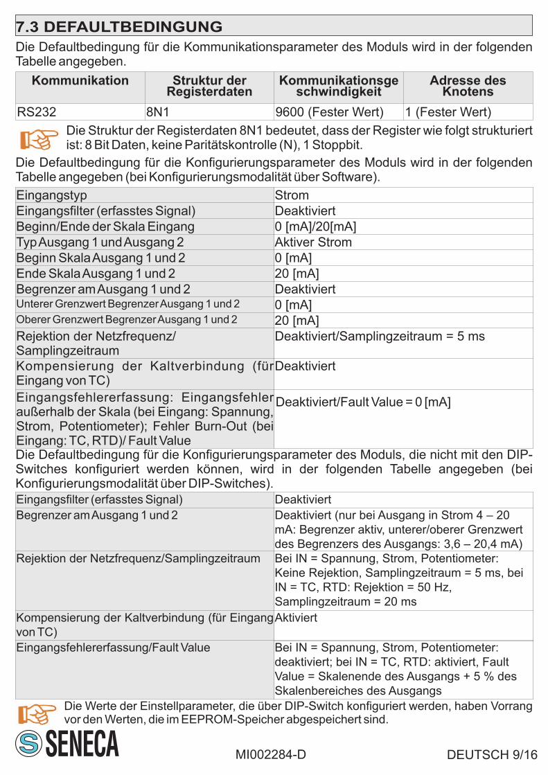
7.3 DEFAULTBEDINGUNG
DEUTSCH 9/16
Die Defaultbedingung für die Kommunikationsparameter des Moduls wird in der folgendenTabelle angegeben.
Die Struktur der Registerdaten 8N1 bedeutet, dass der Register wie folgt strukturiertist: 8 Bit Daten, keine Paritätskontrolle (N), 1 Stoppbit.
Kommunikation Struktur derRegisterdaten
Kommunikationsgeschwindigkeit
Adresse desKnotens
R 32S2 8N1 9600 (Fester Wert) 1 (Fester Wert)
MI002284-D
Eingangstyp Strom
Eingangsfilter (erfasstes Signal) Deaktiviert
Beginn/Ende der Skala Eingang 0 [mA]/20[mA]
TypAusgang 1 undAusgang 2 Aktiver Strom
Beginn SkalaAusgang 1 und 2 0 [mA]
Ende SkalaAusgang 1 und 2 20 [mA]
Begrenzer amAusgang 1 und 2 DeaktiviertUnterer Grenzwert BegrenzerAusgang 1 und 2 0 [mA]Oberer Grenzwert BegrenzerAusgang 1 und 2 20 [mA]
Rejektion der Netzfrequenz/Samplingzeitraum
Deaktiviert/Samplingzeitraum = 5 ms
Kompensierung der Kaltverbindung (fürEingang von TC)
Deaktiviert
Eingangsfehlererfassung: Eingangsfehleraußerhalb der Skala (bei Eingang: Spannung,Strom, Potentiometer); Fehler Burn-Out (beiEingang: TC, RTD)/ Fault Value
Die Defaultbedingung für die Konfigurierungsparameter des Moduls wird in der folgendenTabelle angegeben (bei Konfigurierungsmodalität über Software).
Die Defaultbedingung für die Konfigurierungsparameter des Moduls, die nicht mit den DIP-Switches konfiguriert werden können, wird in der folgenden Tabelle angegeben (beiKonfigurierungsmodalität über DIP-Switches).
Eingangsfilter (erfasstes Signal) Deaktiviert
Begrenzer amAusgang 1 und 2 Deaktiviert (nur bei Ausgang in Strom 4 – 20
mA: Begrenzer aktiv, unterer/oberer Grenzwert
des Begrenzers des Ausgangs: 3,6 – 20,4 mA)
Rejektion der Netzfrequenz/Samplingzeitraum Bei IN = Spannung, Strom, Potentiometer:
Keine Rejektion, Samplingzeitraum = 5 ms, bei
IN = TC, RTD: Rejektion = 50 Hz,
Samplingzeitraum = 20 ms
Kompensierung der Kaltverbindung (für Eingang
von TC)
Aktiviert
Eingangsfehlererfassung/Fault Value Bei IN = Spannung, Strom, Potentiometer:
deaktiviert; bei IN = TC, RTD: aktiviert, Fault
Value = Skalenende des Ausgangs + 5 % des
Skalenbereiches des Ausgangs
Die Werte der Einstellparameter, die über DIP-Switch konfiguriert werden, haben Vorrangvor den Werten, die im EEPROM-Speicher abgespeichert sind.
Deaktiviert/Fault Value = 0 [mA]

DEUTSCH 11/16MI002284-D
Wenn die Weite des Signals am Eingang IN nicht zwischen dem Skalenbeginn und demSkalenbereich des Eingangs liegt, ist derAusgang direkt proportional zum Eingang.Wenn die Weite des Signals am Eingang IN das Intervall überschreitet [Beginn Skala Eingang-2,5 % des Skalenbereiches, Ende Skala Eingang +2,5 % des Skalenbereiches], schaltet derLED ALARM von aus auf an um und die Software zeigt an, dass ein Eingangsfehlervorhanden ist. Wenn die Weite des Signals am Eingang IN das Intervall unterschreitet[Beginn Skala Eingang -2,5 % des Skalenbereiches, Ende Skala Eingang +2,5 % desSkalenbereiches], schaltet der LED ALARM von an auf aus um und die Software zeigt an,dass kein Eingangsfehler vorhanden ist.
Wenn die Weite des Signals am Eingang IN auch die Hardwaregrenzwerte des Moduls (siehefolgende Tabelle) überschreitet, zeigt die Software den Fehler Fail vorhanden an.
Die Bedingung «Alarmstatus vorhanden» entspricht dem Vorhandensein von zumindesteinem der im Folgenden aufgeführten Fehler:
Fehlertyp Beschreibung BetroffenerEingangstyp
Eingangsfehler Die Weite des am Eingang erfassten Signals ist kleiner(g rößer ) a ls der Wer t des Ska lenbeg inns(Skalenbereiches) des Eingangs oder der Sensor amEingang des Moduls ist beschädigt (TC, RTD)
Spannung, Strom,Potentiometer,Thermoelement,Thermowiederstand
Fehler durchDatenverlust imEEPROM-Speicher
/ Alle
Fehler bei derTemperaturerfassung am Eingang
Der Kaltverbindungssensor im Modul istbeschädigt
Thermoelement
-2.5% +2.5%
BeginnSkalaEingang
EndeSkala
Eingang
IN IN
-2.5% +2.5%
IN IN
LED ALARMan aus
LED ALARMan aus
Skalenbereich
Skalenbereich
BeginnSkalaEingang
EndeSkala
Eingang

DEUTSCH 12/16MI002284-D
Eingangstyp Hardwaregrenzwerte des Moduls
Spannung 0 V; 10.5 V~
Strom 0mA; 21 mA~
Potentiometer 0; 100 %
Thermoelementm
mV
TC J: -210°C; 1200°C. TC K: -270°C; 1370°C. TC R: -50°C;1760°C.TC S: -50°C;1760°C. TC T: -270°C; 400°C. TC B: 0;1820°C. TC E: -270°C; 1000°C. TC N: -270°C; 1300°C.V: -10 mV; 70 mV.
RTD RTD=NI100: -60°C; 250°CRTD=PT100, RTD=PT500, RTD=PT1000: -200°C; 600°C
Wenn der LEDALARM an ist (Eingangsfehler vorhanden oder Fehler Fail vorhanden) und dieDiagnose am Eingang aktiv ist, schreibt das Modul in dieAusgänge der Wert Fault Value.

DEUTSCH 13/16MI002284-D
10.2 BLOCKSCHEMA DES MODULS
Block BedeutungFilter 0-19 Filter mit 20 Niveaus am Eingangssignal
A/A Converter analog/analog
Limiter Begrenzer der Weite desAusgangssignals
5
3
5
6
2
1
4
19...28 V
10...40 V~
LIMITER 1
LIMITER 2
11
10
12
AA
9
7
8P
OT/R
TD
TC
VO
LTA
GE
IN
FILTER
(0-19)
POWER
SUPPLY
OU
T 1
OU
TP
UTS
VO
LTA
GE
CU
RR
EN
T
OU
T 2
++
--
OU
TW
AR
DS
OU
TW
AR
DS
INW
AR
DS
INW
AR
DS
INP
UT
Act
ive m
od
ule
(mA
)
Pass
ive m
od
ule
(mA
)

DEUTSCH 14/16MI002284-D
Diese Seite wurde absichtlich frei gelassen.

DEUTSCH 15/16MI002284-D
Diese Seite wurde absichtlich frei gelassen.

DEUTSCH 16/16MI002284-D
Diese Seite wurde absichtlich frei gelassen.

ESPAÑOL 1/16MI002284-S
El presente documento es propiedad de SENECAsrl. Prohibida su duplicación y reproducción sin autorización. El contenido de lapresente documentación corresponde a los productos y a las tecnologías descritas. Los datos reproducidos podrán sermodificados o integrados por exigencias técnicas y/o comerciales.
Índice Pag.1. Datos de Identificación 12. Advertencias preliminares 23. Descripción y características3.1 Descripción del módulo3.2 Características generales
2
4. Especificaciones técnicas4.1 Entradas4.2 Salidas4.3 Conexiones4.4 Aislamientos a 1500 V~4.5 Alimentación4.6 Casas del módulo4.7 Condiciones ambientales4.8 Normativas
2
5. Instrucciones preliminares de uso 56. Conexiones eléctricas6.1 Medidas de seguridad antes del uso6.2 Interfaz serial RS2326.3 Conexiones
5
7. Parámetros para el uso7.1 Parámetros de configuración7.2 Tabla de los conmutadores DIP7.3 Condición predeterminada
6
8. Desmantelamiento y eliminación 99. Códigos de pedido 910. Esquema de disposición del módulo10.1 Esquema de disposición del módulo y LED deseñalización10.2 Esquema del módulo en bloques
10Analógicos y universales
Configurables desdeConmutadores DIP
I N , O U T 1 , O U T 2 ,alimentación:separadosgalvánicamente entre sí
IN, OUT1, OUT2:
SENECA s.r.l.Via Austria, 26 – 35127 – PADOVA – ITALYTel. +39.049.8705355 – 8705359 Fax. +39.049.8706287Sitio web: Soporte técnico:www.seneca.it [email protected] comercio: [email protected]
MANUAL DE INSTRUCCIONES Serie Z
Z170REGMódulo conversor universal con
2 salidas analógicasseparadas galvánicamente
ES

3. DESCRIPCIÓN Y CARACTERÍSTICAS3.1 DESCRIPCIÓN DEL MÓDULOEl módulo Z170REG adopta una señal de entrada universal y la convierte en formatoanalógico, retransmitida en dos salidas independientes entre sí y aisladas.
2. ADVERTENCIAS PRELIMINARES
ESPAÑOL 2/16MI002284-S
3.2 CARACTERÍSTICAS GENERALES
-Posibilidad de elegir si la entrada está:en tensión, en corriente, de potenciómetro, de termopar (TC), determorresistencia (RTD)-Posibilidad de elegir si cada salida está en: tensión, corriente activa / pasiva-Aislamiento igual a 1500 V entre:entrada, alimentación, salida 1 y salida 2 (figura 1)~
-Posibilidad de alimentar el sensor si la entrada está en corriente (borne 7, máx. 17V)-Posibilidad de configurar a través de los conmutadores DIP y software (Easy, disponible enwww.seneca.it):tipo entrada y salidas, inicio/fondo escala para tipo entrada y salidas seleccionadas-Posibilidad de configurar a través software (Easy): filtro entrada, rechazo, burn-out, etc.
4.1 ENTRADA
4. ESPECIFICACIONES TÉCNICAS
Número 1Resolución 14 bit.Periodo demuestreo
Configurable entre: 16.66 ms (rechazo a 60.Hz)o 20 ms (rechazo a 50 Hz).
Filtro Activable en la señal adoptada, nivel configurable entre:0 – 19.Tiempo de respuesta Periodo de muestreo +6 ms.Entradas en tensión1)
Rango de escala configurable: de 0 V a 10 V . Impedancia de entrada:~
120 k .Detección automática si la entrada está fuera escala .W
Entrada en corriente(Módulo activo /pasivo en mA) (1)
Rango de escala configurable: de 0 mA a 20 mAShunt interno: 50 . Alimentación al loop del sensor suministradaW
por:sensor S (módulo pasivo en mA) o por módulo (módulo activo enmA) a través de borne 7 (Máx. 25 mA a Máx. 17 V ) protegido de~
cortocircuito.Detección automática si la entrada está fuera escala.
Entrada depotenciómetro (1)
Rango de escala configurable: de 1 k a 100 k (con R = 330 en paraleloW W W
para añadir externamente). Corriente de activación: 1 mA. Impedancia deentrada: > 5 M .Detección automática si la entrada está fuera escala.W
Entrada de termoparo mV
Tipo de TC:J, K, R, S, T, B, E, N. Impedancia de entrada:> 5 M .W
Detección automática si burn-out.Rango de -10 mV a 70 mV. Impedancia de entrada: > 5 M .W
Entradatermorresistencia (1)
Tipo de RTD:Pt100, Pt500, Pt1000,Ni100. Medición resistencia (para2,3,4 cables) y resistencia de cable. Corriente activación:1.1 mA(PT100) y 0.11 mA (PT1000,PT500). Detección automática si burn-out.
Antes de realizar cualquier operación es obligatorio leer todo el contenido delpresente Manual.El módulo debe ser utilizado exclusivamente por técnicoscualificados en el sector de las instalaciones eléctricas.
La garantía pierde validez en caso de uso inapropiado o alteración del módulo o de losdispositivos suministrados por el Fabricante necesarios para su correcto funcionamiento, y encualquier caso si no han sido seguidas las instrucciones contenidas en el presente Manual.
La reparación del módulo o la sustitución de componentes dañados deben serrealizadas por el Fabricante.

(6) Los valores reproducidos se deben sumar a los errores correspondientes a la entrada seleccionada.
4.2 SALIDASNúmero 2
resolución 14 bit
Limitación amplitudseñal
En cada salida la señal puede ser limitada en amplitud (limitador)
Salida en tensión Configurable entre:0 – 10 V (con mínima resistencia de carga~
conectable en salida: 20 k )W
Salida en corriente(activa o pasiva)
Configurable entre: 0 – 20 mA (con máxima resistencia de cargaconectable en salida:600 , máx. 13V ).«Corriente activa»=salidaW ~
ya alimentada por conectar a módulo pasivo (por ej. multímetro);«corriente pasiva»=salida no alimentada por conectar a móduloactivo (por ej. entrada activa PLC)
Errores referidos alcampo máximo demedición
Precisión Estabilidadtérmica
Error delinealidad
EMI
Salida en tensión (6) 0.1% 0.01%/°K 0.01% < 1%Salida en corriente(activa o pasiva) (6)
0.1% 0.01%/°K 0.01% < 1%
ESPAÑOL 3/16MI002284-S
4.3 CONEXIONESinterfaz RS232 Conector Jack estéreo 3.5 mm en puerto COM (panel frontal)
(1) Para los rangos de escala de entrada, véanse las tablas 3 – 4 (las mismas describen todos losposibles valores de inicio / fondo escala configurables desde Conmutadores DIP para tipo deentrada seleccionado.).(2) Influencia de la resistencia de los cables:0.1 u V / W
(3) Salida cero para t < 250°C(4) Tipo de RTD:Pt100, Pt500, Pt1000, Ni100.Todos los errores se deben calcular sobre el valorresistivo(5) Influencia de la resistencia de los cables:0.005 % / , máx. 20W W
Errores referidos alcampo máximo demedición
Precisión Estabilidadtérmica
Error delinealidad
EMI
Entrada tension ocorriente
0.1% 0.01%/°K 0.05% <1% (2)
Entrada termopar(TP): J, K, E, T, N
0.1% 0.01%/°K 0.2°C <1% (2)
Entrada TP: R, S 0.1% 0.01%/°K 0.5°C <1% (2)Entrada TP: B (3) 0.1% 0.01%/°K 1.5°C <1% (2)compensación juntafría(entrada termopar)
2°C entre 0°C y50°C
/ / /
Entradapotenciòmetro
0.1% 0.01%/°K 0.1% <1%
Entrada RTD (4) 0.1% 0.01%/°K 0.02%( )if t>0°C0.05%( )if t<0°C
<1% (5)

ESPAÑOL 4/16MI002284-S
4.4 AISLAMIENTOS A 1500 Vac
4.5 ALIMENTACIÓNTensión para suministraral módulo
10 – 40 V o bien 19 – 28 V (50 Hz-60 Hz), a través de bornes 2 – 3~ ~
Alimentador Clase 2Absorción delmódulo
Min: 0.5 W; Max: 2 W
Usar el módulo con conductores de cobre.El transformador de alimentación debe cumplir losrequisitos descritos en la norma EN60742 (Transformadores de aislamiento ytransformadores de seguridad).Si el módulo es alimentado con alimentador aislado limitadoen tensión / en corriente, instalar un fusible de capacidad Máx. de 2.5A.
La tensión de aislamiento entre:- alimentación- entrada analógica- salida analógica 1- salida analógica 2es igual a 1500 V (figura 1).~
4.7 CONDICIONES AMBIENTALES
Temperatura defuncionamiento
-10°C – +60°C (UL: -10°C – +60°C)
humedad mín: 30% , Máx: 90% a 40°C no condensante
Grado decontaminación
2 (contaminación ambiental máxima durante el funcionamiento)
Temperatura dealmacenamiento
-20°C – +85°C
4.6 CASAS DEL MÓDULO
Contenedor PBT, colore negro
Dimensiones Anchura L=100mm; altura H=112mm; profundidad W=17,5mm
Tablero de bornes Extraíble de 3 vías: paso bornes 5,08mm, sección borne 2.5 mm2
Grado de protección IP20
El instrumento es conforme a las siguientes normativas-EN 61000-6-4 (emisión electromagnética, en ambiente industrial)-EN 61000-6-2 (inmunidad electromagnética, en ambiente industrial)-EN 61010-1 (seguridad). Instale un fusible de amperaje máximo de 2,5 Aen la proximidad del módulo.
4.8 NORMATIVAS
IN
AC , DC~ ~
OUT-VOUT-mA
1
OUT 2
IN-V
IN-m
AIN
-PO
TIN
-TC
IN-R
TD
PowerSupply
RS 232
OUT-VOUT-mA
OUT 1

ESPAÑOL 5/16MI002284-S
5. INSTRUCCIONES PRELIMINARES DE USOEl módulo ha sido diseñado para ser instalado sobre un carril DIN 46277 en posición vertical.
Está prohibido colocar cualquier objeto que obstruya las aberturas de ventilación.Está prohibido instalar el módulo junto a equipos que generen calor.
6. CONEXIONES ELÉCTRICAS
6.1 MEDIDAS DE SEGURIDAD ANTES DEL USO
Interrumpir la alimentación del módulo antes de conexión:interfaz serialRS232, entradas, salidas.
Separar al menos 5 mm el Z170REG de los módulos adyacentes al mismo, si elZ170REG está destinado a operar en uno de los casos enumerados a continuación:-temperatura de funcionamiento superior a 45°C y al menos una condición defuncionamiento gravosa comprobada;-temperatura de funcionamiento superior a 35 y al menos dos condiciones de℃
funcionamiento gravosas comprobadas;
Se definen «Condiciones de funcionamiento gravosas» las siguientes:-tensión de alimentación superior a:30 V (si es continua), 26 V (si es alterna);~ ~
-el módulo alimenta el sensor en entrada;-configuración de la salida a corriente activa (salida ya alimentada por conectar amódulo pasivo).
Para cumplir con los requisitos de inmunidad electromagnética:-utilizar cables blindados para las señales;-conectar la pantalla a una toma a tierra preferencial para la instrumentación;-distanciar los cables blindados de otros cables utilizados para instalaciones depotencia (inverter, motores, hornos por inducción, etc.).
El módulo está diseñado para intercambiar datos según las modalidades determinadas por elprotocolo ModBUS e implementadas por la interfaz serial RS232.Si el módulo estáconectado a la interfaz RS232, sus parámetros de comunicación (fijos) tienen una estructurade datos de registro del tipo 8N1.El módulo cuenta con un conector Jack estéreo que lepermite conectarse al bus de comunicación (figura 2).
6.2 INTERFAZ SERIAL RS232
2
GND Tx Rx
6.3 CONEXIONES
Asegurarse de que el módulo no esté alimentado con una tensión dealimentación superior a: 40 V (si es continua), 28 V (si es alterna) para no~ !
dañarlo.
ALIMENTACION 2
3
19 – 28 V~10 – 40 V~2 W Max

ESPAÑOL 6/16MI002284-S
7. PARÁMETROS PARA EL USO7.1 PARÁMETROS DE CONFIGURACIÓN
Parámetros modos opciones seleccionablesTipo entrada Software/
DipSwitchTensión-Corriente-Potenciómetro-TC-RTD;si estáen modo Conmutadores DIP, véase la tabla 1
Tipo de entrada mV Software Tensión mV configurable solamente por software
Filtro en entrada Software Activado/Desactivado; si está activado:de 0 a 19.
Inicio/fondo escala entrada Software/DipSwitch
Si está en modo Conmutadores DIP, véansetablas 3 – 4
Tipo salida 1 y 2 Software/DipSwitch
Tensión-Corriente (activa y pasiva); si está enmodo Conmutadores DIP, véase la tabla 2
Software/DipSwitch
Rechazo a la frecuencia dered y periodo de muestreo
Software Sin rechazo: 5 ms (Fast); rechazo a 50 Hz:20 ms; rechazo a 60 Hz: 16.66 ms
Limitador en salida 1 y 2 Software Activado/desactivado (cada uno). Si estádesactivado, los límites son: si OUT=tensión,[0 V; 10.5 V ]; si OUT=corriente, [0 mA; 21 mA]~
Compensación de junta fría(para entrada de termopar)
Software Activado/Desactivado
Detección error de entrada:error de entrada fueraescala o burn-out
Software Activado/Desactivado (para OUT1 y OUT2); siestá activado:configurar los dos «Fault value»(para cada salida)
RTD 3 wires
1210
98
RTD 4 wires
1210
98
ENTRADAS (CONEXIONES SENSORES S) SALIDA 1 SALIDA 2
11(-)
7(+)
Tensione
10
9+
10129
POT8
mV/TC
10
12+
RP
Con R = 330 W
(por añadirexternamente),P=1 k – 100 kW W
10(-)
11(+)
La alimentación alloop (mA) es sumi-nistrada por el sensor
La alimentación alloop (mA) es sumini-strada por el módulo
Módulo pasivo Módulo activo RTD 2 wires
1210
98
Si está en modo Conmutadores DIP, véase tabla 2
5 16 4
+ +
V V
tension
mA mA+ +
++ VextVext
mA mA
corriente
corriente
+ +
- -+ +
+ +- -
+ +
Inicio/fondo escalasalida 1 y 2
ESPAÑOL 7/16
En las siguientes tablas:casilla sin bola significa Conmutador DIP en 0 (estado OFF);casilla con bola significa Conmutador DIP en 1 (estado ON); casilla con X significa:indiferente vale estado ON y estado OFF también.
MI002284-S
7.2 TABLA DE LOS CONMUTADORES DIP
1 2 3 4 5 SignificadoEntradas en tensiónEntrada en corrienteEntrada de potenciómetro (POT)Entrada de termopar J (TC J)Entrada de termopar K (TC K)Entrada de termopar R (TC R)Entrada de termopar S (TC S)Entrada de termopar T (TC T)Entrada de termopar B (TC B)Entrada de termopar E (TC E)Entrada de termopar N (TC N)Entrada de termorresistencia (RTD) Pt100: 2 cablesEntrada de termorresistencia (RTD) Pt100: 3 cablesEntrada de termorresistencia (RTD) Pt100: 4 cablesEntrada de termorresistencia (RTD) Ni100: 2 cablesEntrada de termorresistencia (RTD) Ni100: 3 cablesEntrada de termorresistencia (RTD) Ni100: 4 cablesEntrada de termorresistencia (RTD) Pt500: 2 cablesEntrada de termorresistencia (RTD) Pt500: 3 cablesEntrada de termorresistencia (RTD) Pt500: 4 cablesEntrada de termorresistencia (RTD) Pt1000: 2 cablesEntrada de termorresistencia (RTD) Pt1000: 3 cablesEntrada de termorresistencia (RTD) Pt1000: 4 cables
Tabla 1 - TIPO DE ENTRADA (Conmutadores DIP SW1:TYPE INPUT)
1 2 3 4 5 SignificadoX X X Salida 1 en tensión : 0 - 10 VX X X Salida 1 en tensión : 0 - 5 VX X X Salida 1 en corriente : 0 - 20 mAX X X Salida 1 en corriente : 4 - 20 mA
X X X Salida 2 en tensión: 0 - 10 VX X Salida 2 en tensión: 0 - 5 VX X Salida 2 en corriente: 0 - 20 mAX X Salida 2 en corriente: 4 - 20 mAX X X X Si la salida está en corriente:salida activaX X X X Si la salida está en corriente:salida pasiva
Tabla 2 - TIPO DE SALIDA (Conmutadores SW2: TYPE OUTPUT)
El módulo adopta los parámetros a través de los conmutadores DIP sólo si losconmutadores DIP del módulo están configurados como se reproduce en las tablas 1,2, 3, 4. Para cualquier otra configuración de los conmutadores DIP, TODOS losparámetros son adoptados de la memoria, independientemente de la configuraciónde los conmutadores DIP.

ESPAÑOL 8/16MI002284-S
S 2W Tabla 4 - FONDO ESCALA PARA TIPO DE ENTRADA SELECCIONADA6 7 8 TC B TC E TC N P 100T N 100I P 500T P 1000T
500 °C 50 °C 200 °C 50 °C 20 °C 0 °C 0 °C600 °C 100 °C 400 °C 100 °C 40 °C 50 °C 50 °C800 °C 200 °C 600 °C 200 °C 50 °C 100 °C 100 °C1000 °C 300 °C 800 °C 300 °C 80 °C 150 °C 150 °C1200 °C 400 °C 1000 °C 400 °C 100 °C 200 °C 200 °C1500 °C 600 °C 1200 °C 500 °C 150 °C 300 °C 300 °C1800 °C 800 °C 1300 °C 600 °C 200 °C 400 °C 400 °C
S 2W Tabla 4 - FONDO ESCALA PARA TIPO DE ENTRADA SELECCIONADA6 7 8 Tension Corriente POT TC J TC K TC R TC S TC T
0.5 V 1 mA 40% 100 °C 200 °C 400 °C 400 °C 50 °C1 V 2 mA 50% 200 °C 400 °C 600 °C 600 °C 100 °C2 V 3 mA 60% 300 °C 600 °C 800 °C 800 °C 150 °C3 V 4 mA 70% 400 °C 800 °C 1000 °C 1000 °C 200 °C4 V 5 mA 80% 500 °C 1000 °C 1200 °C 1200 °C 250 °C5 V 10 mA 90% 800 °C 1200 °C 1400 °C 1400 °C 300 °C10 V 20 mA 100% 1000 °C 1300 °C 1750 °C 1750 °C 400 °C
S 1W Tabla 3 - INICIO ESCALA PARA TIPO DE ENTRADA SELECCIONADAT6 7 8 TC B (*) TC E TC N P 100T N 100I P 500T P 1000T
0 °C -200 °C -200 °C -200 °C -50 °C -200 °C -200 °C500 °C -100 °C -100 °C -100 °C -30 °C -100 °C -100 °C600 °C 0 °C 0 °C -50 °C -20 °C -50 °C -50 °C700 °C 100 °C 100 °C 0 °C 0 °C 0 °C 0 °C800 °C 150 °C 200 °C 50 °C 20 °C 50 °C 50 °C1000 °C 200 °C 300 °C 100 °C 30 °C 100 °C 100 °C1200 °C 400 °C 500 °C 200 °C 50 °C 200 °C 200 °C
S 1W Tabla 3 - INICIO ESCALA PARA TIPO DE ENTRADA SELECCIONADA6 7 8 Tension Corriente POT TC J TC K TC R TC S TC T
0 V 0 mA 0% -200 °C -200 °C 0 °C 0 °C -200 °C0.5 V 1 mA 10% -100 °C -100 °C 100 °C 100 °C -100 °C1 V 2 mA 20% 0 °C 0 °C 200 °C 200 °C -50 °C2 V 3 mA 30% 100 °C 100 °C 300 °C 300 °C 0 °C4 V 4 mA 40% 200 °C 200 °C 400 °C 400 °C 50 °C5 V 5 mA 50% 300 °C 300 °C 600 °C 600 °C 100 °C10 V 10 mA 60% 500 °C 500 °C 800 °C 800 °C 150 °C
Para evitar descargas electrostáticas que pudieran dañar el módulo, realizar laconfiguración del mismo a través de los Conmutadores DIP con laalimentación eléctrica interrumpida.
(*) Salida cero para t < 250°C.
y� ON �
z� OFF

7.3 CONDICIÓN PREDETERMINADA
ESPAÑOL 9/16
La condición predeterminada para los parámetros de comunicación del módulo se reproduceen la siguiente tabla.
Estructura datos de registro igual a 8N1 significa que el registro está estructurado dela siguiente manera: 8 bit de datos, ningún control de paridad (N), 1 bit de stop.
Comunicación Estructura datos deregistro
Velocidad decomunicación
Dirección del nodo
R 32S2 8N1 9600 Valor fijo 1 Valor fijo
MI002284-S
Tipo entrada CorrienteFiltro en entrada (señal adoptada) DesactivadoInicio/Fondo escala entrada 0 [mA] / 20 [mA]Tipo salida 1 y salida 2 Corriente activaInicio escala salida 1 y 2 0 [mA]Fondo escala salida 1 y 2 20 [mA]Limitador en salida 1 y 2 DesactivadosExtremo inferior limitador de la salida 1 y 2 0 [mA]Extremo superior limitador de la salida 1 y 2 20 [mA]Rechazo a la frecuencia de red/periodo demuestreo
Desactivada/periodo de muestreo = 5 ms
Compensación de junta fría (para entrada deTP)
Desactivada
Detección error en entrada: error de entradafuera escala (en caso de entrada: tensión,corriente, potenciómetro); error de burn-out(en caso de entrada:TC, RTD)/ Fault value
Desactivada/Fault value= 0 [mA]
La condición predeterminada para los parámetros de configuración del módulo se reproduceen la siguiente tabla (si el modo de configuración es desde software).
La condición predeterminada para los parámetros de configuración del módulo no configurables con losconmutadores DIP se reproduce en la siguiente tabla (si el modo de configuración es desde conmutadoresDIP).Filtro en entrada (señal adoptada) DesactivadoLimitador en salida 1 y 2 Desactivados (sólo en caso de salida en corriente
4 – 20 mA:limitador activado, extremo inferior-superior limitador de la salida: 3.6 – 20.4 mA)
Rechazo a la frecuencia de red/periodo demuestreo
Si IN=tensión, corriente, potenciómetro:norechazo, periodo de muestreo = 5 ms siIN=TC, RTD: rechazo= 50 Hz, periodo demuestreo = 20 ms
Compensación de junta fría (para entrada deTP)
Activada
Detección error de entrada/Fault value Si IN=tensión, corriente,potenciómetro:desactivada; si IN=TC,RTD:activada, Fault value= fondo escala desalida +5 % del rango de escala de salida
Los valores de los parámetros de configuración configurados medianteconmutadores DIP tienen prioridad respecto a los valores memorizados en memoriaEEPROM.

ESPAÑOL 10/16
El panel frontal del módulo comprende 2 LED, el estado de cada uno de los cualescorresponde a:
LED estado del LED significado del LEDPWR Encendido (luz verde) El módulo es alimentado correctamente
ALARM Encendido (luz amarilla) Estado de alarma presente
Apagado Estado de alarma ausente
MI002284-S
10.1 ESQUEMA DE DISPOSICIÓN DEL MÓDULO Y LED DE SEÑALIZACIÓNDIMENSIONES DEL MÓDULO LED DE SEÑALIZACIÓN
112 m
m
17,5 mm
100,0 mm
1 2 34 5 6
7 8 910 11 12
S
PWR
ALARM
Z170REG
COM
4
10. ESQUEMA DE DISPOSICIÓN DEL MÓDULO
Eliminación de los residuos eléctricos y electrónicos (aplicable en la Unión Europea y en los otros paísescon recogida selectiva). El símbolo presente en el producto o en el envase indica que el producto no serátratado como residuo doméstico. En cambio, deberá ser entregado al centro de recogida autorizado parael reciclaje de los residuos eléctricos y electrónicos. Asegurándose de que el producto sea eliminado demanera adecuada, evitar un potencial impacto negativo en el medio ambiente y la salud humana, quepodría ser causado por una gestión inadecuada de la eliminación del producto. El reciclaje de losmateriales contribuirá a la conservación de los recursos naturales. Para recibir información más detallada,le invitamos a contactar con la oficina específica de su ciudad, con el servicio para la eliminación deresiduos o con el proveedor al cual se adquirió el producto.
8. DESMANTELAMIENTO Y ELIMINACIÓN
Código de pedido DescripciónZ170REG Duplicador universal con separación galvánica
PM001601 Cable de conexión para comunicación RS232 (de DB9-F)
9. CODIGOS DE PEDIDO

ESPAÑOL 11/16MI002284-S
Si la amplitud de la señal de entrada IN está comprendida entre inicio escala entrada y fondoescala entrada, la salida es directamente proporcional a la entrada.Si la amplitud de la señal de entrada IN supera el intervalo [inicio escala entrada -2.5 % delrango de escala, fondo escala entrada +2.5 % del rango de escala], el LED ALARM pasa deapagado a encendido y el software señala error de entrada presente.Si la amplitud de la señal de entrada IN disminuye dentro del intervalo [inicio escala entrada-2.5 % del rango de escala, fondo escala entrada +2.5 % del rango de escala], el LEDALARMpasa de encendido a y el software señala error de entrada ausente.
La condición «Estado de alarma presente» corresponde a la presencia de al menos uno delos errores enumerados a continuación:Tipo de error Descripción Tipo de entrada
afectadoError de entrada La amplitud de la señal adquirida en entrada
es inferior (superior) al valor de inicio escala(fondo escala) de entrada o bien el sensor enentrada al módulo está dañado (TP, RTD)
Tensión, corriente,potenciómetro, termopar,termorresistencia
Error de pérdida dedatos en la memoriaEEPROM
/ Todos
Error deadquisicióntemperatura enentrada
El sensor de junta fría en el interior del móduloestá dañado
Termopar
-2.5% +2.5%
Inicioescala deentrada
Fondoescala en
entradaIN IN
-2.5% +2.5%
IN IN
LED ALARMoff on
LED ALARMon off
Rango de escala
Rango de escala
Inicioescala deentrada
Fondoescala en
entrada

ESPAÑOL 12/16MI002284-S
Si la amplitud de la señal de entrada IN supera además los límites hardware del módulo(véase la siguiente tabla), el software señala error de fail presente.
Tipo de entrada Límites hardware del móduloTension 0 V; 10.5 V~Corriente 0 mA; 21 mA~
Potenciómetro 0; 100 %
Termopar
mV
Si TP J: -210°C; 1200°C. Si TP K: -270°C; 1370°C. Si TP R: -50°C;1760°C. Si TP S: -50°C;1760°C. Si TP T: -270°C; 400°C. SiTP B: 0;1820°C. Si TP: -270°C; 1000°C. Si TP: -270°C; 1300°CSi mV: -10 mV; 70 mV.
RTD Si RTD=NI100: -60°C; 250°CSi RTD=PT100, RTD=PT500, RTD=PT1000: -200°C; 600°C

ESPAÑOL 13/16MI002284-S
10.2 ESQUEMA DEL MÓDULO EN BLOQUES
Bloque significado (fig. 5)FILTER 0-19 Filtro de 20 niveles en la señal adquirida en entradaA/A ConversorAnalógico /AnalógicoLIMITER Limitador de la amplitud de la señal en salida
5
3
5
6
2
1
4
19...28 V~10...40 V~
LIMITER 1
LIMITER 2
11
10
12
AA
9
7
8P
OT
/RT
DT
CV
OLT
AG
E
IN
FILTER(0-19)
POWERSUPPLY
OU
T1
OU
TP
UT
S
VO
LTA
GE
CU
RR
EN
T
OU
T2
++
--
OU
TW
AR
DS
OU
TW
AR
DS
INW
AR
DS
INW
AR
DS
INP
UT
Act
ive m
odule
(mA
)
Pass
ive m
odule
(mA
)

ESPAÑOL 14/16MI002284-S
Esta página ha sido intencionalmente dejada en blanco.

ESPAÑOL 15/16MI002284-S
Esta página ha sido intencionalmente dejada en blanco.

ESPAÑOL 16/16MI002284-S
Esta página ha sido intencionalmente dejada en blanco.