Embed Size (px)
Citation preview

04.2018
ITALIA ITALYSEDE e STABILIMENTO HEADQUARTERSVia G. Di Vittorio, 440053 VALSAMOGGIA Loc. Monteveglio (Bo) - ItalyTel. +39/051/6714811 - Fax. +39/051/6714858E-mail: [email protected] [email protected] [email protected]: www.sitiriduttori.it
RIDUTTORIMOTORIDUTTORIVARIATORI CONTINUIMOTORI ELETTRICI C.A./C.C.GIUNTI ELASTICI
GEARBOXESGEARED MOTORSSPEED VARIATORSA.C./D.C. ELECTRIC MOTORSFLEXIBLE COUPLINGS
SPASOCIETÀ ITALIANA TRASMISSIONI INDUSTRIALI
®
CINA CHINAShanghai SITI Power Transmission Co., Ltd. Block A, No.558 Xuan Qiu Rd. Sanzao Industrial Park,Pudong New Area, Shanghai, P.R.China P.C.:201300 Tel:+86-21-68060500 - Fax:+86-21-68122539 E-mail: [email protected]: www.sh-siti.com
POLONIA POLANDSITI-TECH Sp. z o.o.Milejowice, ul. Napêdowa 426-652 Zakrzew POLANDE-mail: [email protected]: www.sititech.pl
ROMANIA ROMANIAS.C. SITI BALKANIA SRLPiatra Craiului, 7 (Zona Ind. La Dibo) - Hala4 Comp.7 - Jud Prahova - RomaniaTel. +40-244434243 - Fax. +40-244434243E-mail: [email protected]: www.sitibalkania.ro
SOCIETÀ ITALIANA TRASMISSIONI INDUSTRIALISPA
TM
MD
U-M
UI-M
I®
WORMGEARBOXES INSTRUCTION AND SPARE PARTS MANUAL
EN
1409
1 - w
ww
.ser
tek.
it

MIB5 B51 B53 B52 V1 V3
FFBRFBM
FBML
STANDARD
FP
STANDARD
IB3 V5 B8 V6 B6 B7
A
STANDARD
B
STANDARD
V
STANDARD
U-MUB5 B51 B53
STANDARD
B8
B3
B6 B7
V5 V6
K
L
D
E
G IH
1
2
3
4
5
67
max 0,2-0,3
2
1
I 130 M10I 150 M12I 175 M12
°C
F
B CA

ENGLISH
1 / 21
Abstract1. Introduction ..................................................................................................................................................... 2
1.1. Foreword ................................................................................................................................................ 21.2. Manufacturer's identification data ............................................................................................................. 21.3. Communications with the technical assistance ......................................................................................... 21.4. List of contents of the manual ................................................................................................................. 21.5. Purpose and validity of the manual .......................................................................................................... 21.6. Addressees of the manual ...................................................................................................................... 31.7. Choice and qualification of the personnel ................................................................................................. 31.8. Symbology used ..................................................................................................................................... 31.9. Glossary ................................................................................................................................................. 31.10. Warranty .............................................................................................................................................. 3
2. Accident prevention advices ............................................................................................................................. 42.1. General warnings ................................................................................................................................... 42.2. Residual risks ......................................................................................................................................... 42.3. Advices for the use in a potentially explosive atmosphere ......................................................................... 52.4. Installation of parts on account of the customer ........................................................................................ 5
3. General information ......................................................................................................................................... 63.1. Expected use ......................................................................................................................................... 63.2. Prohibited uses ....................................................................................................................................... 63.3. Declaration of incorporation ..................................................................................................................... 63.4. Gearbox identification data ...................................................................................................................... 7
3.4.1. Identification name plate ................................................................................................................. 73.5. Technical specifications ........................................................................................................................... 73.6. Stocking ................................................................................................................................................. 8
4. Handling and transport .................................................................................................................................... 84.1. Handling and transport ............................................................................................................................ 8
5. Set up ............................................................................................................................................................. 95.1. Check and predisposition ........................................................................................................................ 95.2. Mounting positions .................................................................................................................................. 95.3. First filling in of the gearbox .................................................................................................................... 95.4. Set up .................................................................................................................................................. 105.5. Assembling of the primary reduction unit on the gearbox ........................................................................ 11
6. Instructions for the use of the gearbox ........................................................................................................... 126.1. Preliminary checks ................................................................................................................................ 126.2. Running in ............................................................................................................................................ 126.3. Checks during running .......................................................................................................................... 13
6.3.1. Check of running temperature ....................................................................................................... 136.3.2. Measure of the running temperature ............................................................................................. 146.3.3. Check of the torque limiter (optional device) .................................................................................. 14
7. Lubrication .................................................................................................................................................... 147.1. Lubrication ............................................................................................................................................ 147.2. Type of oil ............................................................................................................................................ 157.3. Oil amount ............................................................................................................................................ 16
8. Maintenance .................................................................................................................................................. 168.1. Maintenance ......................................................................................................................................... 168.2. Ordinary maintenance ........................................................................................................................... 16
8.2.1. Cleaning ...................................................................................................................................... 168.2.2. Check of oil level ......................................................................................................................... 16
8.3. Periodical maintenance operations ......................................................................................................... 178.3.1. Oil replacement ............................................................................................................................ 178.3.2. Possible replacement of shaft seals .............................................................................................. 188.3.3. Check of bearings ........................................................................................................................ 19
8.4. Adjustment of the torque limiter (optional device) .................................................................................... 198.5. Table of tightening torques of attaching hardware ................................................................................... 208.6. Troubles, causes, corrective actions ...................................................................................................... 21
9. Scrapping and material disposal ..................................................................................................................... 219.1. Scrapping and material disposal ............................................................................................................ 21

ENGLISH
2 / 21
1. Introduction
1.1. Foreword
SITI S.p.A. thanks you for the trust granted and reminds you that your product is the result of a work of improvement ourengineers are continuously pursuing, due to a constant research in the section.Reading and understanding the present publication is an essential condition for a correct set up and following installation.The Assistance network is anyway at your disposal in order to help you to settle all possible doubts that might arise.Reproduction, recording or alteration, even partly, of this publication is forbidden without a written authorization by theSITI S.p.A.
1.2. Manufacturer's identification data
SOCIETÀ ITALIANA TRASMISSIONI INDUSTRIALI®
GEARBOXESGEARED MOTORSCONTINUOUS SPEED VARIATORSELECTRIC MOTORS A.C./D.C.ELASTIC COUPLINGS
HEADQUARTER and FACTORY
Via G. Di Vittorio, 440053 VALSAMOGGIA Loc. Monteveglio (Bo) - ItalyTel. +39/051/6714811Fax. +39/051/6714858E-mail: [email protected]: www.sitiriduttori.it
1.3. Communications with the technical assistance
For whatever communication with the Technical Assistance Center, please always mention the gearbox technical dataappearing on the name plate, located on the unit. These data will allow a whole identification of the unit (⇒ Identificationname plate, 7).
1.4. List of contents of the manual
The present manual provides the installation, use and maintenance instructions of the product and refers to its use in theconditions as it will be clearly described in the following sections (⇒ Expected use, 6).The present manual has been written in Italian as original language and thereafter translated into other languages.Therefore, the italian language constitutes the "ORIGINAL INSTRUCTIONS MANUAL", while the versions drawn up inother languages are to be considered "TRANSLATIONS OF THE ORIGINAL INSTRUCTIONS". Should you be convincedthat the translation is wrong or missing a few parts, you are kindly requested to get in touch with the SITI S.p.A., who willprovide to supply all the convenient clarifications and possibly to amend the translation where necessary.The description texts are sometimes equipped with a reference (A, B, C, etc..) to some images, which are shown in thereverse part of the front and rear cover.
1.5. Purpose and validity of the manual
The present manual offers the instructions for set up, use and maintenance related to worm gearboxes of the series I-MI,U-MU and MD and complies with all the law dispositions, to the directives and to the rules which are in force at the timeof the sale. The copy of the manual delivered along with the gearbox cannot be considered inadequate simply becauseit has been subsequently updated due to new experiences. Should any possible changes, adjustments etc.. be carriedout to the marketed units in a following moment, they neither will force the manufacturer to come in action retrospectivelyon products previously supplied nor to consider the same products and the related manual as missing or unsuitable.Possible further inclusions to the manual that the manufacturer will feel convenient to send to customers will have to besaved along with the manual, which they will represent integral part of.The warranty related to the good running and performance and full compliance of the unit with the expected service isstrictly dependent on the correct application of instructions held in the present manual.

ENGLISH
3 / 21
1.6. Addressees of the manual
The present manual is addressed to:• the manager of the plant;• the personnel in charge of set ups;• the personnel in charge of the maintenance.The manual has to be guarded by a responsible person and kept, in the best status of preservation, in a place suitableto be always available for the consultation by the persons it is addressed to.In case of loss or deterioration, the replacing documentation is to be requested to the manufacturer, indicating thereference data given on the identification plate (⇒ Identification name plate, 7).
1.7. Choice and qualification of the personnel
For the operations of handling, set up and maintenance, the user will have to commit the task to operators who haveat their disposal the following features:• Degree of education and training are adequate in view of the operation to be carried out.• Knowledge of what is illustrated in the present manual in relation to the operation to be carried out.• Knowledge of the accident prevention rules which are in force at the moment of use.• Physical conditions suitable to the operation to be carried out.• Equipment and use of certified individual protection devices.
1.8. Symbology used
Instructions are tied to symbols aimed at making the reading easier, by clarifying the kind of information supplied.
Generalized danger for the safety of human beings.
Important remarks in view of a correct usage without causing damages to the equipments.
Instructions related to units expected for set up in environments having a potentially explosive atmosphere,complying with the directive 2014/34/UE (ATEX).
1.9. Glossary
P.P.E.Acronym of Personal Protective Equipment.
1.10. Warranty
• Our warranty has a validity of one year, starting from the date of invoice of the product. It is limited exclusively tothe free of charge repair or to the free replacement of the parts we recognize defective; checks intended to ascertainwhether warranty can apply will be always carried out in the plant of the Seller or by one of the authorized branches.The claim can neither give rise to the cancellation of orders and not even to a high reduction of deliveries nor to thesuspension of payments by the Buyer; not even the payment of a compensation in money of any kind effected bythe Seller can be acceptable.Our warranty will expire if the pieces sent back as defective ones will prove to have been in any way altered or repairedwithout our previous written authorization; moreover, it will expire in case the Buyer fails in anyone of his contractualobligations, especially in reference to the payment conditions.
• Our warranty does not cover any damage or failure due to external factors, a missing maintenance, overloads,unsuitable lubrication, wrong choice of the type of unit, assembling error, caused by external components and bycomponents subject to wear and deterioration as well as damages arising as a consequence of the transport carriedout on account of the customer or through a transporter designed by the customer, considering that the shipment isalways carried out on account and at risk afforded by the Buyer.
• Expenses (like for instance disassembling, labour, re-assembling, transport, board and lodging), which are undertakendue to the outer service of personnel of the Seller, even after acknowledgment of the warranty, are always on chargeof the Buyer. On charge of the Seller, there are to be considered the components acknowledged under warranty andthe time necessary for the replacement of the same.
• Any sort of compensation is not included and not even direct or indirect damages can be claimed (even towards thirds).• The requests for repair under warranty and/or out of warranty are to be communicated by written through the suitable
module to SITI S.p.A. in view of the acceptance of the repair.

ENGLISH
4 / 21
Material to be repaired either under warranty or anyway subject to troubles, will be withdrawn by our Company onlyif it is sent back at free port following up a written request, and it will be sent back with transport freights coveredby the customer.
2. Accident prevention advices
2.1. General warnings
• It is prohibited to bring any kind of modification to the gearbox, without a previous authorization granted by themanufacturer.
• It is prohibited to use the gearbox in a potentially explosive atmosphere, unless the unit has been purposely pre-arranged for the use in such kind of atmosphere.
• The surface of a gearbox while operating might reach high ranges of temperature, such to cause skin burns. It isstrictly recommended to check the temperature value of the outer surfaces of the gearbox, prior to enforcing any kindof service on the unit (⇒ Measure of the running temperature, 14).
• Whenever one is operating near the gearbox, it is recommended to wear a protection equipment, suitable for theoperation to be carried out. All clothes worn while operating near a unit are to be close-fitting to the body. It is stronglyrecommendable to refrain from wearing ties, necklaces or belts, which might get caught by or squeeze in the rotatingparts of the unit. It is necessary to always wear individual own protection devices, as called for by the manual in viewof carrying out some kinds of service on the units.
2.2. Residual risks
In the stage of design and calculation of the gearboxes, an accurate analysis has been carried out about the risks,which the operators in charge of maintenance might be subject to, while they effect the manoeuvres and other kinds ofmaintenance and, due to this, all possible precautions have been taken, in order to make the gearbox safer and morereliable.There are anyway a few conditions of risk depending on the installation type and on the operating conditions, which maybe removed just by using simple precautions, as indicated on the manual in the related paragraphs.
Risk: crushing
Eventuality / risk locationFall / crash of the gearbox during transport / set up stages.
Protections / precautionsWear all P.P.E. called for.Comply with the instructions given in the manual (⇒ Handling and transport, 8).
Risk: burns
Eventuality / risk locationBy touching the gearbox during the use and maintenance.
Protections / precautionsWear all the P.P.E. called for.Comply with the instructions given in the manual (⇒ Measure of the runningtemperature, 14) and (⇒ Oil replacement, 17).

ENGLISH
5 / 21
Risk: irritation of skin / eyes
Eventuality / risk locationReplacing / re-filling oil during the maintenance.
Protections / precautionsWear all the P.P.E. called for.Comply with the instructions given in the manual (⇒ Oil replacement, 17).
2.3. Advices for the use in a potentially explosive atmosphere
Danger!Mixtures of explosive gases or high powder concentrations may cause serious damages especially whenthey get in touch with hot rotating parts of the gearbox.
Set up, connection, start up, maintenance or repair works on gearboxes are to be accomplished only byspecialized and qualified technicians, who have to comply with the following prescriptions:• Follow all manufacturer's instructions.• Take care and comply with all notice marks and information signs applied on the units.• Strictly follow the specific rules related to the installation on which the unit is operating.• Strictly follow all rules which are in force in the country of manufacture (protection against explosions,
safety, risk prevention).
2.4. Installation of parts on account of the customer
Caution!Prior to being set in motion, the gearbox must be provided with a few parts, essential in view of a full safety in the useand operations.
After set up, the user is requested to equip the gearbox with adapted repairs, suitable to protect rotating parts connectinginput shafts and output shafts. On the protections, the following pictographs are to be applied:
Do not remove the protections.
Obligation to keep protections effective.
Caution!The SITI S.p.A. declines any responsibility in case of damages occurring to things or persons, caused by the use of thegearbox without taking all the due protections as mentioned here above.

ENGLISH
6 / 21
3. General information
3.1. Expected use
The unit has been designed and manufactured in order to directly transmit the rotational motion, operating a revolutionspeed reduction between input and output shafts.Performance and limitation of use are clearly specified in the technical/commercial catalogue, which is available uponrequest or may be downloaded from the site www.sitiriduttori.it
Only in case ATEX mounting is purposely requested, the gearbox can be used for operating in environmentsmeeting the following requirements:Group: IICategory 2 G / 2 DProtection mode (not electrical): ExhModes of protection used: "c" constructive safety - "k" immersion in liquidGas / Dust Group: IIC / IIICZone: 1 / 21EPL: Gb / DbMaximum surface temperature: T4 / T135 °CII 2G Exh IIC T4 GbII 2D Exh IIIC T135 °C Db-20 °C ≤ Ta ≤ + 60 °C
Marking according to IEC EN 80079-36: 2016
3.2. Prohibited uses
The gearbox cannot be used for purposes different from the expected ones.The standard gearbox cannot be used in environments characterized by a potentially explosive atmosphere. For such ause, it is necessary to require the special version fulfilling the directive 2014/34/UE (ATEX).
3.3. Declaration of incorporation
In compliance with the Machinery Directory 2006/42/CE, the gearbox, being intended to be built in and/or fitted on othermachines or machine components, is considered a "component", therefore it cannot be put in service as long as themachine, on which it will be built in, has not been declared in conformance with the Machinery Directory 2006/42/CE.
Remark:The subject product complies with the above mentioned features and with the ones given on the catalogue which is inforce at the production date. SITI S.p.A. reserves the right to change them, in order to adapt them to the technology ormaterial variations occurred.

ENGLISH
7 / 21
3.4. Gearbox identification data
3.4.1. Identification name plate
All units are equipped with an identification name plate A, showing the following pieces of information:1. P/N of the gearbox2. Type of gearbox3. Transmission ratio4. Description5. Additional description6. Order number7. Progressive number of pieces/whole number of pieces of the order8. Bar code and QRcode (in view of component traceability)
In case of units fulfilling the directive 2014/34/UE (ATEX), the name plate B is applied, on which even thefollowing additional pieces of information are given:• Type of gearbox• Identification number• Transmission ratio• P/N of the gearbox.• Compliance with ATEX classification.
On some units there might be the name plate C with the following pieces of information:• type of gearbox;• identification number;• transmission ratio;• P/N of the gearbox
Remark:The name plate must be always preserved in a way to be readable in relation to all data shown on it, providing periodicallyto its cleaning.Should a name plate deteriorate and/or result to be not readable any longer, even in one only of the data appearing onit, it is recommended to require a new name plate to the manufacturer, mentioning the data which are still readable, andthen provide to replace the name plate.
3.5. Technical specifications
Dimensions and performanceFeatures, dimensions and performance of gearboxes are given in the related technical/commercial catalogue availableon request or they can be downloaded from the website www.sitiriduttori.it.
NoiseThe level of noise emitted by a gearbox during a running period at full load in the worst operating conditions is alwaysremarkably below the value of 70 dB (A).

ENGLISH
8 / 21
3.6. Stocking
If, prior to set up, a period of stocking is expected, it is necessary to adhere to the following rules:• Avoid to stock outdoor, in areas exposed to the bad weather and with excessive humidity.• Always avoid the direct contact with the floor; for instance, use pallets or materials of another nature which anyway
are such to insulate the product.• For times of stocking longer than 60 days, it is recommended to coat with anti-oxidation products shafts, flanges and
anyway all not painted surfaces.• For times of stocking longer than 6 months, it is necessary to coat with grease all non machined parts, in order to
prevent oxidation. Completely fill in the gearboxes with oil, keeping attention that the fill-in/breather plug is placed inthe upper zone; of course, at the time of setting the unit up, it will be necessary to recover the proper oil amounts(⇒ Oil amount, 16).
4. Handling and transport
4.1. Handling and transport
Caution!Read carefully and comply with the following instructions prior to handling the gearbox.
P.P.E. Helmet, safety shoes and protection gloves
• Usually the gearbox is delivered in the condition of assembled and packed unit. Should the product be deliveredpacked in cardboard containers, handle the packed product with suitable means of weight-lifting in compliance withthe law rules.
• Do not stop or move below suspended loads during lifting and transport operations.
The packages which include more gearboxes are to be lifted and handled with appropriate and suitable means, adequateto the dimensions and weights involved, like transpallets, lift trucks, overhead travelling cranes using ropes, cables, beltsor suspension chains.
Single gearboxes or geared motors packed or deprived of the package must be lifted with the following operational modes:
• if their weight is equal to or lower than 15 kg they can be moved by hand;• if their weight is higher than 15 kg, they must be moved with suitable lifting and transport means, as indicated above.
Especially, the unpacked units are to be hooked and secured with a sling, as it has been described as an examplein the sketches D, arranging ropes or chains as it is requested by the product conformation.
On the gearboxes I-MI130/150/175 there is a tapped hole conceived for fitting an eyebolt (not supplied), by means ofwhich it is possible a safe hook (see table of dimensions). In the case of geared motors, a second belt has to be arranged,in order to distribute and correctly balance the weight.
Caution!• Make sure that the grip of the load is steady and safe, even in case of oscillations.• The eyebolt is suitable for lifting a single gearbox or a geared motor and not for lifting the whole complex of components
which it will be fitted on.

ENGLISH
9 / 21
5. Set up
5.1. Check and predisposition
Prior to proceeding with the gearbox mounting, the following checks are to be carried out:
• After unpacking the gearbox, it is recommended to carry out a visual check, intended to realize whether there isfull compliance with the order, whether the product integrity is assured and whether there is absence of defects onall gearbox parts. Should it be found out that there is no compliance with the order and/or presence of failures ordamages, this will have to be promptly communicated to the SITI S.p.A.
• Make sure that the product is suitable to the requested use.• Check the appropriateness of the structures on which the unit will be mounted, in relation to the actions and reactions
due to the load application.• Check the conformance of the mounting position indicated in the order acknowledgment with the wished one
(⇒ Mounting positions, 9). A possible change of the mounting position can be accomplished only after havingconsulted the SITI S.p.A. and after having received their authorization, otherwise warranty and the possible conformitywith the directive 2014/34/UE (ATEX) will expire.
• Make sure that the spaces available for set up and mounting can comply with the need of providing an easyassembling, maintenance, access to the plugs (⇒ Mounting positions, 9), air circulation, etc.
• Check whether the unit has been supplied complete with lubricant.Units without plugs are filled in by SITI S.p.A. and are provided with lifetime lubrication.Units with plugs might be delivered with or without lubrication oil, depending on the type and size.Therefore, it is strictly necessary to check whether there is actually lubricant inside the unit, by watching through thesuitable inspection plug (fig. E), firstly providing to directing the gearbox in conformance with the actual expectedmounting position (⇒ Mounting positions, 9). In the opposite case, please proceed with oil filling in (⇒ First fillingin of the gearbox, 9).
5.2. Mounting positions
K e L sketches show the typical mounting positions of a gearbox with the corresponding identification abbreviations (e.g..:B3, B52, V5, etc.). On a side of the gearbox, the positions of fill-in, inspection and unloading plugs are even shown withcircular symbols, if they are present in the gearbox.
Fill-in plug Level plug Unloading plug
5.3. First filling in of the gearbox
P.P.E. Protection gloves and mask glasses• Check that the unloading plug, located in the lowest position, and the level plug have been correctly fastened.• For filling oil in, use the fill-in/breather plug, located in the upper gearbox portion. Oil amount to be filled in is given
in the table (⇒ Oil amount, 16), but we point out that said amounts have a merely indicative value; the user willhave in any case to fill oil in, until the oil level visible at sight on the level plug has been reached, once the unit hasbeen already mounted in the correct mounting position (⇒ Mounting positions, 9).

ENGLISH
10 / 21
5.4. Set up
Caution!All actions of set up, assembling and setting on account and on behalf of the buyer must be accomplished by qualifiedpersonnel. A wrong set up might lead to dangerous situations for the safety of the personnel and could give rise to seriousor even irreparable damages to the product itself and to the connected machine.
Gearboxes are supplied already assembled in their main parts. Therefore, set up consists in placing and then fixing theunit in the place where it will operate, connecting input and output shafts to their matching parts, and carrying out theelectric connections of the electric motor, whenever needed.While setting a gearbox up, it is requested to adhere to a few strictly severe prescriptions:
• Make sure that the environment, where the unit will operate, does not highlight any unexpected conditions, like:- potentially explosive atmosphere;- immersion in water or corrosive solution;- vapours, radiations.For applications in peculiar environmental conditions, please consult the SITI S.p.A.
• It is necessary to avoid, or at least to reduce as much as possible narrowing and throttling in the air passages andespecially the presence of heat sources located nearby gearboxes and such to be able to remarkably affect thetemperature of the refrigerating air. Furthermore, it is necessary to prevent from an insufficient air circulation, whichmight compromise the regular heat removal from hot gearbox parts.
• Prior to setting the gearbox up, make sure that fill-in, unloading and level inspection plugs have been placed in thecorrect location in relation to the requested mounting position of the unit (⇒ Mounting positions, 9) and that therecommended oil has been used for filling the unit (⇒ Lubrication, 14).
• It is essential to fit the gearbox in a way such to avoid that it is subject to vibrations while operating. In fact, vibrations,in addition to causing noise, give rise to other kinds of problems, like the possible progressive unscrewing of theconnection screws as well as an increase of loads acting on the inner parts submitted to fatigue stresses.
• Fixing surfaces are to be clean and are to have a sufficient microfinish in order to arrange that a good friction coefficientis available. In the screws and in the connection plains it is strictly necessary to use self-locking stickers.
• It is recommended to avoid as much as possible the fact of assembling cantilever mounted pinions and to reduce tothe highest possible extent the stress of chains and belts. Should outer loads be there, it is suggested to use pinsand positive stops.
• Prior to going ahead with the assembling, it is necessary to take particular care to clean accurately and lubricate themating surfaces, in order to avoid possible oxidations and seizures.
• All parts which are press-fitted on the gearbox hollow shaft (made in tolerance range H7) are to be carried out withtheir fitting diameter made in a tolerance range h6. Wherever the kind of application requires a slight interference fit,it is possible to provide a fitting with a tolerance range female-male of the matching parts in (H7 - j6).
• Never use the hammer for assembling and disassembling fitted parts, but use the tapped holes provided on the shaftheads for suitable removal implements.
• It is of prior importance, in view of a good performance of the unit in operating conditions, to take care with the greatestattention of a good alignment of the gearbox with respect to the motor and to the machine to be driven. Whenever itis possible, it is recommended to fit elastic or self-aligning couplings. It is even suggested to proceed with a particularaccuracy whenever an outrigger bearing is fitted, because possible errors in the alignment of this component wouldunavoidably involve the rise-up of overloads which would consequently destroy a bearing or break the shaft.
• When three-phase asynchronous electric motors are used and their start-up occurs in no load conditions or anywayunder very restricted loads, it is necessary to accomplish very smooth starting times, very limited starting currents,even very restricted stresses and, whenever necessary, use the star/delta starting system.
• Whenever the application involves overloads of long duration, frequent shocks and danger of lock off, it is imperativeto fit a motor saving system, electronic torque limiters, hydraulic couplings, safety couplings or control units.
• In case of use with a service factor involving several starting under load, it is recommended to make use of a motorprotection by means of thermal sensors, in order to prevent the rise-up of dangerous overloading conditions for themotor, which might lead motor windings to overheat and thus to melt and fail.
• During the possible painting of the machine on which the unit is fitted, it is strictly recommended to protect the outeredge of shaft seals, aiming at preventing paint to make rubber dry, thus compromising the sealing effect.

ENGLISH
11 / 21
It is advisable to use plastic inserts whenever there is a risk of electro-chemical corrosion between gearboxand actuator unit (due to the connection of different metals).Moreover, please provide all bolts with plastic washers! The plastic material used is to have a surface electricresistance < 109 Ω.Provide the outer structure with earth connection, furthermore use bolts with earth connection of the motorfor the geared motors.Assure a convenient and sufficient cooling air flow and make sure that there is no return of heated air, comingfrom other devices. The cooling air has not to exceed a temperature of 40 °C.
5.5. Assembling of the primary reduction unit on the gearbox
When it is expected that the assembling of the primary reduction unit will have to be carried out by the customer, proceedas follows (fig. H):• fit the pinion 1 on the motor shaft;• place the O ring 2 on the pinion;• place the O ring 4 and the ring 3 over the screw 5 and screw up this one on the pinion;• fill in the primary reduction unit with the amount and the type of oil indicated (⇒ Lubrication, 14);• fit the motor on the primary reduction housing 6, paying attention not to damage the gasket 7.
Remark:During assembling, keep the position shown on the figure H.

ENGLISH
12 / 21
6. Instructions for the use of the gearbox
6.1. Preliminary checks
Prior to the start up, a few very important checks are to be carried out:• Make sure that the set up has been accomplished in a correct way, complying with all the prescriptions given on the
chapter devoted to set up.• Find out the temperature of the environment where the unit is mounted and pre-arrange a thermometer suitable to
register the surface temperature (⇒ Measure of the running temperature, 14).
Prior to starting a gearbox mounted in an environment with potentially explosive atmosphere,according to the ATEX directive, the following checks are to be carried out. ✓
Inspect the packing, in order to check the status of goods at the moment of delivery.The following pieces of information given on the gearbox name plate correspond to the kind ofexplosive atmosphere approved: group, category, anti-deflagration zone, class of maximum allowed surfacetemperature.Do you feel sure that we are not in presence of a potentially explosive atmosphere, consisting of oils, gases,acids, vapours, radiations active during the gearbox set up?Does the ambient temperature meet the values given on paragraph (⇒ Check of runningtemperature, 13)?Make sure that gearboxes are sufficiently ventilated and that there are no outer sources of heat inlet (e.g.through connectors). The cooling air must not exceed a temperature of 40 °C.Does mounting position correspond to the expected one? (⇒ Mounting positions, 9).
Caution!Any change of the mounting position can be carried out only if authorized by the manufacturer. ATEXcompliance will expire in case of a missing consultation with the manufacturer.Is oil level correct? (with the unit located exactly in the requested mounting position) (⇒ Check of oillevel, 16)Are unloading and inspection plugs (whenever expected), as well as breather valves all easily accessible?Have input and output parts been mounted according to the ATEX rules?In case of motors driven by a frequency converter: make sure that the motor is regularly certified in view ofits usage in combination with a frequency converter.The calibration and scaling of the technical parameters of the frequency converter are to be such to preventthe overloading of the gearbox.
6.2. Running in
All gearboxes are to be submitted to a running in time of about 300-400 hours.It is recommended to increase progressively during the running in time the transmitted power up to a limit of the 50-70% of the maximum allowed power (in the first running hours).During this time, values of temperature higher than the standard ones might occur.Made exception for the units already supplied as lubricated by SITI S.p.A. with a lifetime lubricant, on which no oilreplacement is requested, on all the units supplied by the SITI S.p.A. without oil it is recommended an oil change afterrunning in, in order to assure higher reliability and a longer gearbox time of life (⇒ Oil replacement, 17).

ENGLISH
13 / 21
6.3. Checks during running
6.3.1. Check of running temperature
P.P.E. Heat insulated glovesDuring the gearbox running time, it is necessary to keep the inner temperature controlled.Temperature reached inside a unit depends on several factors:• the kind of kinematism used for the transmission;• type and amount of lubricant;• main features and structure of the gearbox;• input and output speed;• mounting position;• applied power;• ambient temperature.
Temperature check may be effected by measuring its value on the gearbox outer surface. The max. surface temperatureis achieved after about three running hours of continuous running and has not to overcome, in any operating condition,the differential value of 50 °C, compared with the ambient temperature, this being achieved with the max. allowable loadapplied. If this occurs in the period of time subsequent to running in and in standard operating conditions, the unit has tobe stopped immediately and it is necessary to consult the SITI S.p.A.
Remark:Please keep in mind that this value, like many other values of the max. admissible temperature mentioned in this manual,refers to environmental conditions characterized by an ambient temperature of 20 °C, poor conditions of ventilation (airspeed ≤0.5 m/s) and applies when running in time has been completed.Moreover, it refers to a correct selection and usage of the units, i.e. to a use with an effective service factor higher orequal to the minimum service factor requested by the heaviness of the application.Even slight variations in comparison with these conditions, both environmental and operating ones, might remarkablyadversely affect the temperature of the gearbox. During the stage of running in (first 300-400 operating hours), the valuesof temperature increase ΔT might be even 25% higher.
Standard shaft seals are made in nitrile rubber compounds NBR and are suitable to operatein the range of standard operating temperatures included between about -15 °C and +85°C. Should temperature inside the unit reach and keep for meaningful time intervals somevalues out of this range, it is necessary to require a special version of the gearbox, which isto be equipped with shaft seals made in fluorinated compounds FKM (trademark: Viton) fortemperatures higher than +85 °C or in silicon rubber compound called VMQ, for temperatureslower than -15 °C.
During the running of a unit mounted in a potentially explosive atmosphere, according to thedirective ATEX, the following check operations are to be carried out. ✓
Measure the surface temperature after about 3 hours of continuous service.The temperature differential in comparison with the ambient temperature has not to overcome a value of50 °C.Should said temperature differential ΔT be higher, stop the gearbox immediately and consult themanufacturer.

ENGLISH
14 / 21
6.3.2. Measure of the running temperature
P.P.E. Heat insulated gloves
Caution!Do not touch the gearbox prior to providing to the detection of the actual temperature with a thermometer.
For measuring the outer temperature of the housing, it is necessary to equip oneself with a thermometer provided with atemperature detection sensor (fig. F). Any evaluation effected by touching the gearbox with a hand might be dangerousand additionally not reliable at all. In optimal conditions of use, the temperature of the housing rises up of at least 15-20°C compared with the environment and the values of temperature usually reached by the housing during the runningconditions are mostly too high to be born by the human skin. The fact of believing that a gearbox warms up too muchbecause it is not possible to keep the hand on its housing is a statement missing any rational foundation. In fact, as soonas the temperature is even slightly above the value of 50 °C, the most of people are unable to keep their hand over thegearbox housing, although this is still a completely acceptable running temperature of an unit.It is important to make sure that the running temperature at which a gearbox stabilizes in rated operating conditions, whenthere are the same modes of use, is more or less a constant value, considering that this a signal that the unit is operatingwithout the possible rise up of adverse effects.The gearbox surface temperature must be detected in the area of transition from gearbox to motor, where the locationof the electric motor clamp hinders a correct ventilation.
6.3.3. Check of the torque limiter (optional device)
P.P.E. Heat insulated glovesIf the gearbox is equipped with the torque limiter, check during running that said device is correctly adjusted:• in conditions of standard load, the sliding of the coupling has not to occur in any way;• on the contrary, in conditions of overloading, the sliding of the coupling has to occur imperatively.
Shouldn't these conditions be complied with, stop the unit and adjust correctly the torque limiter (⇒ Adjustment of thetorque limiter (optional device), 19).
7. Lubrication
7.1. Lubrication
All units of the series U-MU, MD and the units of the series I-MI up to the size 90 included are supplied already filled inwith lubrication oil and are without oil plugs, considering that it has been used a synthetic oil for lifetime lubrication, whichdoes not require any replacement or any refilling during all the operating life of the gearbox.On request, all gearboxes of the series U-MU and I-MI up to size 90 included may be supplied in a special versioncomplete with fill-in, unloading and level plugs.On the contrary, the gearboxes I-MI 110/130/150/175 are supplied without oil and are equipped with fill-in, unloading andlevel plugs. The primary reduction units supplied complete with motor or with solid input shaft are filled in with lubricantby SITI S.p.A. In all other cases, the filling in of oil of primary reduction units is committed to the customer.For the lifetime lubrication, the Company SITI S.p.A. is currently using the synthetic oil type OLIO SYNT CLP-PG ISOVG 320 PAG.For all those cases when the filling in of oil is committed to the customer, this one can use either synthetic oils for lifetimelubrication or mineral oils for non lifetime lubrication, but anyway one of the lubrication oils recommended (⇒ Type ofoil, 15). In the choice of the oil to use, the customer has even to take care of the ambient temperature.In the following tables, we show the oils, both synthetic and mineral ones, that we suggest and we recommend to strictlycomply with these indications, even when there is the occasional need of adding oil for recovering the correct level.
Remark:It is recommended never to mix mineral oils with synthetic oils.

ENGLISH
15 / 21
7.2. Type of oil
Synthetic oils (lifetime lubrication) TYPICAL OIL PROPERTIESOLIO SYNT CLP-PG ISO VG 320 PAG
MAKE TYPE Density (kg/dmc) 1.069SHELL OMALA S4 WE 320 Kinematic viscosity at 40 °C 321 cStIP TELIUM OIL VSF 320 Pour point - 39 °CKLÜBER SYNTHESO D 320 EP Viscosity index 230BP ENERGOL SGXP 320 Flash point (c.o.c) 270 °CTEXACO SYNLUBE CLP 320 FZG test overcomes the stage > 12
Admissible ambient temperature: -10 ÷ +30 °C
Remark:It cannot be mixed with mineral oils and it is not compatible withcellulose nitrate based paints and with seals made in naturalrubber.
Mineral oils (non lifetime lubrication) TYPICAL OIL PROPERTIESOLIO MIN CLP ISO VG 220
MAKE TYPE Initial boiling point > 280 °CSHELL OMALA OIL 220 Solubility in water NegligibleIP MELLANA OIL 220 Density (kg/dmc) 899 kg/m3 at 15 °CMOBIL MOBILGEAR 630 Flash point (c.o.c) 200 °CESSO SPARTAN EP220 Higher flash limit in air 10%(v/v) (typical)
Lower flash limit in air 1%(v/v) (typical)Admissible ambient temperature: -5 ÷ +35 °C
Self-ignition temperature >320 ºC (typical)Kinematic viscosity 220 mm2/s at 40 °CVapour density (air=1) >1 at 20 °CPour point -18 °CRemark:It cannot be mixed with synthetic oils.
Note:For applications at an ambient temperature lower than the admissible one, as indicated, please contact our TechnicalService Office.

ENGLISH
16 / 21
7.3. Oil amount
I-MI Pre-lubricated with synthetic oil ISO VG 320 PAG To be filled in onaccount of the customer
Size I 25 I 30 I 40 I 50 I 60 I 70 I 80 I 90 I 110 I 130 I 150 I 175Oil amount (l) 0.030 0.035 0.15 0.19 0.39 0.55 0.85 1.70 1.80 2.20 5.70 6.80
U-MU Pre-lubricated with synthetic oil ISO VG 320 PAGSize U 30 U 40 U 50 U 63 U 75 U 90 U 110Oil amount (l) 0.035 0.13 0.19 0.33 0.50 0.90 1.40
MD Pre-lubricated with synthetic oil ISO VG 320 PAGSize MD 126 MD 160 MD 200 MD 220 MD 250Oil amount (l) 0.9 1.9 3.5 4.0 7.5
Primaryreduction units
Synthetic oil ISO VG 320 PAG
Size P 63 P 71 P 80 P 90 P 110Oil amount (l) 0.04 0.05 0.08 0.08 0.45
8. Maintenance
8.1. Maintenance
The program of maintenance includes the service actions of ordinary type, providing inspections, checks and auditseffected directly by the operator and/or by qualified personnel committed to the usual maintenance and service actionsof periodical type, including replacement of parts or recording, developed by personnel, who has been purposely trainedon behalf of the manufacturer through specific courses or special issues.
8.2. Ordinary maintenance
8.2.1. Cleaning
Carry out periodically the cleaning of the outer surface of the gearbox and of the air channels for the ventilation, in orderto assure a satisfactory thermal exchange coefficient towards outside.
8.2.2. Check of oil level
For the units supplied by SITI S.p.A. without oil plugs and filled in with synthetic oil, the fact of checking oil level is neitherrequested nor possible, due to the missing level plug.Should the user, however, detect oil leakages or should he make sure that some running malfunction events take place,which induce him to assume that the oil level might have been meaningfully reduced, we recommend to apply to theTechnical Assistance Dept. SITI S.p.A., in order to ask for an advice about the way to behave.
Caution!The damages a gearbox might be subject to, should it operate with a poor oil amount, are extremely serious and quick,and many times are fully irreparable!

ENGLISH
17 / 21
A poor amount of lubricant, in addition to the fact of not allowing the proper lubrication of all innerparts, might adversely affect the thermal exchange conditions and, due to the highly reducedrefrigerating and heat removal power, gives rise to the inner running temperature increase,especially on the mating surfaces of teeth flanks.It is suggested to often make sure, through quick visual checks, that no oil leakages areoccurring through shaft seals, gaskets, connecting flanges, attaching hardware of covers, endcaps etc....
A more careful check of oil level has to be carried out at sufficiently frequent time intervals. This check is to be effectedthrough the level plug when the unit is standing still and is sufficiently cool (fig. E).Should it be ascertained, through the same level plug, that an inner dirt sedimentation has occurred, it is strictly necessaryto make sure that no foreign material, such as powder, sand, water or anything else has penetrated into the gearboxhousing and anyway replace oil (⇒ Oil replacement, 17).Should oil level have sunk down and shallowed below the recommended values, it is necessary to fill oil in, up to restoringthe correct level.
8.3. Periodical maintenance operations
8.3.1. Oil replacement
For the oil replacement after the running in time, comply with the instructions given on the paragraph (⇒ Running in, 12)and (⇒ Lubrication, 14).
The interval of periodical oil replacement depends on the conditions of use, briefly summarized in the following prospect.
Oil temperature (°C) Service Time interval between oil changes (hours)< 60 Continuous
Intermittent50008000
> 60 ContinuousIntermittent
25005000
Remark:Data given in the prospect refer to a lubrication with use of mineral oils.
Synthetic oils, if used in the range of standard temperatures from -15 °C up to +85 °C, can be used even for a lifetimelubrication.This occurs in the case of all units already supplied by the SITI S.p.A. with a synthetic base lubrication.In the case of large and expensive gearboxes, on which all possible maintenance actions are very costly, it isrecommended for safety reasons to carry out an oil change, even if synthetic, whenever any maintenance repair servicehas been effected, provided that a period of operating time of 8000 thru 10000 service hours has occurred.
Remark:Unloading of oil is to be carried out in hot conditions, with the gearbox at a temperature of about 40-45 °C, but not beyondthis range, in order to prevent from possible burnings.
Caution!Please be very careful in order to avoid to spill oil on the ground and pay attention to behave in full conformance withthe environmental rules in force in the country of usage.

ENGLISH
18 / 21
P.P.E. Protection gloves and mask glasses• Unscrew the fill-in/breather plug.• Unscrew the unloading plug located down and let oil completely flow out (this is particularly important in case of
changing lubricant from a mineral to a synthetic oil or the opposite).• Check whether the level plug is clean and transparent. In case it is not, unscrew and clean it.• Screw again the unloading plug.• Fill in the units from the upper hole. The oil amount to be filled in is indicated in the table (⇒ Oil amount, 16), but
we point out that the mentioned amounts do have a simply indicative value; the user has to fill oil in, until the oillevel visible at sight through the transparent level plug has been achieved (having already mounted the unit in theexpected mounting position).
• Screw again the fill-in breather plug located above.
8.3.2. Possible replacement of shaft seals
The running time and thus the endurance time of a shaft seal is affected in a conclusive way by the operating temperaturein the mating area, by the possible chemical reactions which might occur between rubber compound and lubrication fluidand by the status of preservation of the shaft seal.Replacement of the shaft seal is necessary if:• a good serviceability of the sealing function is missing, and due to this an oil leakage towards outside of the unit is
occurring;• it is being effected a revision of the machine or of the installation.Whenever a shaft seal is not developing its sealing function any longer, it is necessary to provide as soon as possibleto its replacement, in order to prevent a leakage extending along the time, as well as a damage possibly extended toother components.
At the time of fitting a new shaft seal, it is needed:• to take a particular care while handling the shaft seal and make sure of the intactness of the product (possibly avoid too
long times of storage, which might give rise to a premature aging, especially if there is an excessive level of humidity);• always check that the shaft seal seat is in a perfect status, in other words it is free of longitudinal or oriented scores,
fingerprints, engravings, cuttings, marks or surface failures;• take care to prevent that the shaft seal lip of the new seal operates exactly over the same trace left clearly by the
previous one;• whenever it is made sure that a deterioration of the shaft seal mating area has occurred, involving a depth greater
than 0.2-0.3 mm, we strongly advise not to fit the new shaft seal and to get in touch with a workshop of our Assistance,which will provide to check whether there is any chance of recovering the shaft, and in any case will issue a diagnosisabout the possible reasons of the damage occurred (fig. G);
• fit the shaft seal in a way to be perpendicular to the axis and with the lip completely free and not overturned or pinched;• position the shaft seal in a way that the sealing lip is oriented towards the fluid which is to be sealed, or on the side
where a higher pressure is exerted;• on shaft seals without a dust lip, spread grease in the outer area of the lip;• fill in with grease the interspace between sealing and dust lip;• coat with grease the shaft seal seat on the shaft;• never use sealants, otherwise shaft seal lip or shaft surface would get smirched and thus would quickly deteriorate;• exert the fitting force as close as possible to the shaft seal outer diameter;• neither lock axially the seal nor submit it to a strong force;• always use suitable toolings, in order to prevent possible damages to the shaft seal lip, due to the presence of threads,
outlet chamfers, sharp edges, keyways;• always protect the lip and its seat on the shaft, whenever one provides to repaint the unit or the machine on which
it is fitted.All above mentioned precautions do have the objective to avoid that a shaft seal might operate in dry conditions, especiallyduring the first shaft turns, because otherwise too high temperatures might be achieved in the contact areas, which wouldimmediately cause a deterioration of the materials shaft seal is made of: shaft seal getting harder, scorings, change ofcolourfulness.

ENGLISH
19 / 21
8.3.3. Check of bearings
In every gearbox there are bearings even of different kind, subject to loading and lubrication conditions which mightchange as a function of the transmission ratio and of the type of application.For this reason, considering the variability of the parameters involved, it is not defined a planned replacement interval,but it is requested a series of checks on bearings, allowing to understand when to proceed with the replacement.Therefore, it is necessary to plan periodical checks of noise level and vibrations of bearings, using suitable instruments,according the the Table frequency of checks.In case a deterioration of the measured values is detected, it is necessary to stop the machine and carry out an innerinspection of the gearbox, involving, whenever necessary, our Technical Dept.Should the possible failure of a bearing and the following machine stop mean a danger for people, carry out a monitoringof vibrations and noise with continuity.
Table frequency of checks
Code Subject of the check FrequencyA Sound level (noise) On three-month basisB Vibrations On three-month basisC Temperature On three-month basis
8.4. Adjustment of the torque limiter (optional device)
P.P.E. Protection gloves
In order to adjust the torque limiter, it is needed (fig. I):• to stop the unit;• fold the tooth 1 of the anti-unscrewing washer;• turn the nut 2 in a clockwise direction, in order to increase the transmissible
torque, or turn it in counterclockwise direction, in order to decrease saidtorque;
• refold the tooth of the washer inside one of the little grooves.In the reported graph, the values of the max. transmissible torque as a functionof the number of turns of the nut are given for each gearbox size. However, itis to be pointed out that the values given in the graph are merely indicative anda correct and refined adjustment has to be carried out by means of differenttries (⇒ Check of the torque limiter (optional device), 14).
M= Transmitted torque (Nm)N= Number of turns of the threaded nut

ENGLISH
20 / 21
8.5. Table of tightening torques of attaching hardware
For all gearboxes and possible accessories, please strictly adhere to the following values of the tightening torques.
Screw threadsClass 8.8
Tightening torque forsteel and cast iron (Nm)
Tightening torquefor aluminium (Nm)
M4 2.9 2.3M5 6 4.8M6 10 8M8 25 20
M10 49 39M12 86 69M14 135 108M16 210 168M18 290 232M20 410 328

ENGLISH
21 / 21
8.6. Troubles, causes, corrective actions
The conditions of malfunctioning, which might be reasonably expected, related to the single operating conditions of theunit, are reported; in the columns of the following table, the kind of trouble, the operating function and the componentwhich might be the reason of the failure are accurately described.
TROUBLE POSSIBLE CAUSES CORRECTIVE ACTIONSFaulty electric motor connection. Check the connection.Faulty motor. Replace the motor.
Motor does not start.
Wrong motor sizing. Replace the motor.Mechanical overloading. Check the mechanical parts driven by the
motor-gearbox.Motor and gearbox reach a toohigh temperature.
Sizing of the motor-gearbox group wrong. Replace the motor-gearbox group.Faulty motor. Replace the motor.Motor current absorption and/
or motor temperature are toohigh.
Wrong motor sizing. Replace the motor.
Faulty gearbox. Repair or replace the gearbox.Wrong sizing of the gearbox. Replace the gearbox.Mounting position not complying with theone for which the gearbox has beenarranged.
Make sure that the gearbox is in compliancewith the order.
Gearbox reaches a too hightemperature.
Insufficient amount of lubricant. Re-fill new lubricant in, until the oil levelcorresponding to the level plug has beenreached.
Worn or faulty shaft seals. Replace shaft seals.Oil leakages through theshafts. Worn shaft seal seat on shafts. Replace shaft seals and fit the new ones in a
slightly shifted position or otherwise replaceshafts.
Flanges not sufficiently tightened. Tighten flanges.Oil leakages through themating surfaces betweenflanges/covers and housing.
Faulty gaskets between mating plains. Replace gaskets, making sure that thesealing surfaces are perfectly machined.
The gearbox emits a noisesimilar to a beat.
Faulty gear teeth. Apply to the Technical Assistance Service.
Insufficient amount of lubricant. Re-fill new lubricant in, until the oil levelcorresponding to the level plug has beenreached.
Faulty or worn gears. Apply to the Technical Assistance Service.
The gearbox emits a noisesimilar to a whistle.
Faulty or uncorrectly fitted bearings. Apply to the Technical Assistance Service.
9. Scrapping and material disposal
9.1. Scrapping and material disposal
As soon as the gearbox has achieved its maximum limit of usage, it will have to be dismantled and scrapped.Remove all oil from the gearbox, keeping in mind that exhausted oil has a strong adverse effect on the environment.After scrapping, the operation of getting rid of the materials and of the lubricant will have to be accomplished in fullcompliance with all rules and law dispositions which are in force at the moment in the country of usage.All operations related to getting rid of materials will have to be effected by qualified and authorized Companies; it is atask of the Company that is in charge of getting rid of materials to make sure that said Companies are complying withthe requested National and International Directives.

NOTE ANMERKUNGNOTES
NOTES NOTASNOTAS

R.1/10
I 30
Pos. Descrizione Description Beschreibung Description Descripción Descrição
1 CORPO HOUSING GEHAEUSE CARCASSE CUERPO CARCAÇA
2 VITE SENZA FINE WORM SHAFT SCHNECKENWELLE VIS SANS FIN TORNILLO SINFÍN ROSCA SEM FIM
3 CORONA WORM WHEEL SCHNECKENRAD COURONNEHÉLICOÏDALE CORONA COROA
4 LINGUETTA KEY KEIL LANGUETTE LENGÜETA CHAVETA
5 CUSCINETTO BEARING LAGER ROULEMENT COJINETE ROLAMENTO
6 CUSCINETTO BEARING LAGER ROULEMENT COJINETE ROLAMENTO
7 ANELLO DI TENUTA SHAFT SEAL WELLENDICHTUNG JOINT D’ÉTANCHÉITÉ AN. DE RETENCIÓN RETENTOR
8 ANELLO DI TENUTA SHAFT SEAL WELLENDICHTUNG JOINT D’ÉTANCHÉITÉ AN. DE RETENCIÓN RETENTOR
9 ANELLO SEEGER SNAP RING SEEGERRING ANNEAU D’ARRÊT ANILLO SEEGER ANEL ELÁSTICO
10 ANELLO SEEGER SNAP RING SEEGERRING ANNEAU D’ARRÊT ANILLO SEEGER ANEL ELÁSTICO
11 CAPPELLOTTO END CAP ENDKAPPE CHAPEAU DE FERMETURE CAPERUZA TAMPÃO
Pour consulter le catalogue pièces de re-change, veuillez vous adresser à l’Assistance Technique de SITI S.p.A. et demander la docu-mentation sur papier ou le CD-ROM interactif (si disponible).
PEÇAS DE REPOSIÇÃO
Para consultar o catálogo das peças de repo-sição entre em contato com a Assistência Téc-nica da SITI S.p.A. e peça o catálogo em papel ou o CD-ROM interativo (quando disponível).
PTBPIEZAS DE REPUESTOPIÈCES DE RECHANGE
Para consultar el catálogo de piezas de re-puesto, póngase en contacto con la Asistencia técnica de SITI S.p.A. y solicite la documenta-ción en papel o el CD-ROM interactivo (si está disponible).
FRB
ESB
To check the spare parts catalogue, contact the SITI S.p.A. Technical Service Department and require a hard copy of the documentation or the interactive CD-ROM (when available).
Per consultare il catalogo ricambi rivolgersi all’Assistenza Tecnica della SITI S.p.A. e richie-dere la documentazione cartacea o il CD-ROM interattivo (quando disponibile).
Für den Ersatzteilkatalog wenden Sie sich bitte an die technische Abteilung von SITI S.p.A.; auf dieser Weise erhalten Sie die Papierunterlagen oder die interaktive CD-ROM (falls verfügbar).
ERSATZTEILESPARE PARTSPARTI DI RICAMBIO DEENIT
R.2/10
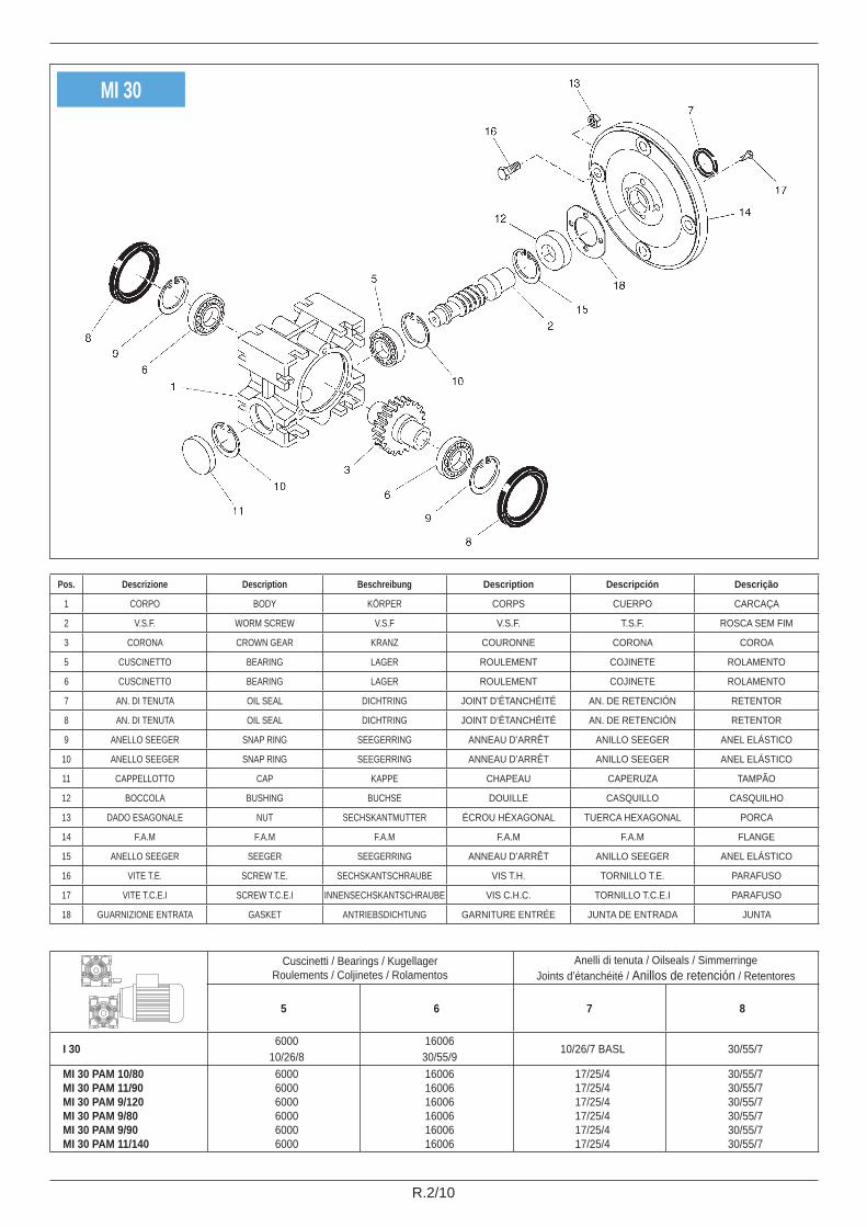
MI 30
Cuscinetti / Bearings / KugellagerRoulements / Coljinetes / Rolamentos
Anelli di tenuta / Oilseals / SimmerringeJoints d’étanchéité / Anillos de retención / Retentores
5 6 7 8
I 30 600010/26/8
1600630/55/9
10/26/7 BASL 30/55/7
MI 30 PAM 10/80MI 30 PAM 11/90MI 30 PAM 9/120MI 30 PAM 9/80MI 30 PAM 9/90MI 30 PAM 11/140
600060006000600060006000
160061600616006160061600616006
17/25/417/25/417/25/417/25/417/25/417/25/4
30/55/730/55/730/55/730/55/730/55/730/55/7
Pos. Descrizione Description Beschreibung Description Descripción Descrição
1 CORPO BODY KÖRPER CORPS CUERPO CARCAÇA
2 V.S.F. WORM SCREW V.S.F V.S.F. T.S.F. ROSCA SEM FIM
3 CORONA CROWN GEAR KRANZ COURONNE CORONA COROA
5 CUSCINETTO BEARING LAGER ROULEMENT COJINETE ROLAMENTO
6 CUSCINETTO BEARING LAGER ROULEMENT COJINETE ROLAMENTO
7 AN. DI TENUTA OIL SEAL DICHTRING JOINT D’ÉTANCHÉITÉ AN. DE RETENCIÓN RETENTOR
8 AN. DI TENUTA OIL SEAL DICHTRING JOINT D’ÉTANCHÉITÉ AN. DE RETENCIÓN RETENTOR
9 ANELLO SEEGER SNAP RING SEEGERRING ANNEAU D’ARRÊT ANILLO SEEGER ANEL ELÁSTICO
10 ANELLO SEEGER SNAP RING SEEGERRING ANNEAU D’ARRÊT ANILLO SEEGER ANEL ELÁSTICO
11 CAPPELLOTTO CAP KAPPE CHAPEAU CAPERUZA TAMPÃO
12 BOCCOLA BUSHING BUCHSE DOUILLE CASQUILLO CASQUILHO
13 DADO ESAGONALE NUT SECHSKANTMUTTER ÉCROU HÉXAGONAL TUERCA HEXAGONAL PORCA
14 F.A.M F.A.M F.A.M F.A.M F.A.M FLANGE
15 ANELLO SEEGER SEEGER SEEGERRING ANNEAU D’ARRÊT ANILLO SEEGER ANEL ELÁSTICO
16 VITE T.E. SCREW T.E. SECHSKANTSCHRAUBE VIS T.H. TORNILLO T.E. PARAFUSO
17 VITE T.C.E.I SCREW T.C.E.I INNENSECHSKANTSCHRAUBE VIS C.H.C. TORNILLO T.C.E.I PARAFUSO
18 GUARNIZIONE ENTRATA GASKET ANTRIEBSDICHTUNG GARNITURE ENTRÉE JUNTA DE ENTRADA JUNTA

R.3/10
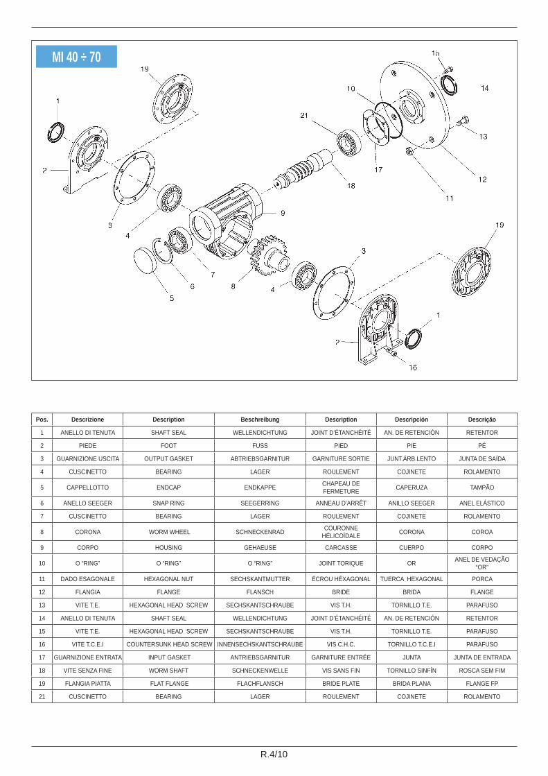
I 40 ÷ 70
Pos. Descrizione Description Beschreibung Description Descripción Descrição
1 ANELLO DI TENUTA SHAFT SEAL WELLENDICHTUNG JOINT D’ÉTANCHÉITÉ AN. DE RETENCIÓN RETENTOR
2 PIEDE FOOT FUSS PIED PIE PÉ
3 GUARNIZIONE USCITA OUTPUT GASKET ABTRIEBSGARNITUR GARNITURE SORTIE JUNT. ÁRB. LENTO JUNTA DE SAÍDA
4 CUSCINETTO BEARING LAGER ROULEMENT COJINETE ROLAMENTO
5 CAPPELLOTTO END CAP ENDKAPPE CHAPEAU DE FERMETURE CAPERUZA TAMPÃO
6 ANELLO SEEGER SNAP RING SEEGERRING ANNEAU D’ARRÊT ANILLO SEEGER ANEL ELÁSTICO
7 CUSCINETTO BEARING LAGER ROULEMENT COJINETE ROLAMENTO
8 CORONA WORM WHEEL SCHNECKENRAD COURONNE HÉLICOÏDALE CORONA COROA
9 CORPO HOUSING GEHAEUSE CARCASSE CUERPO CORPO
14 AN. DI TENUTA SHAFT SEAL WELLENDICHTUNGEN JOINT D’ÉTANCHÉITÉ AN. DE RETENCIÓN RETENTOR
16 VITE T.C.E.I COUNTERSUNK HEAD SCREW INNENSECHSKANTSCHRAUBE VIS C.H.C. TORNILLO T.C.E.I PARAFUSO
18 VITE SENZA FINE WORM SHAFT SCHNECKENWELLE VIS SANS FIN TORNILLO SINFÍN ROSCA SEM FIM
19 FLANGIA PIATTA FLAT FLANGE FLACHFLANSCH BRIDE PLATE BRIDA PLANA FLANGE FP
20 LINGUETTA KEY KEIL LANGUETTE LENGÜETA CHAVETA
21 CUSCINETTO BEARING LAGER ROULEMENT COJINETE ROLAMENTO
R.4/10
Pos. Descrizione Description Beschreibung Description Descripción Descrição
1 ANELLO DI TENUTA SHAFT SEAL WELLENDICHTUNG JOINT D’ÉTANCHÉITÉ AN. DE RETENCIÓN RETENTOR
2 PIEDE FOOT FUSS PIED PIE PÉ
3 GUARNIZIONE USCITA OUTPUT GASKET ABTRIEBSGARNITUR GARNITURE SORTIE JUNT.ÁRB.LENTO JUNTA DE SAÍDA
4 CUSCINETTO BEARING LAGER ROULEMENT COJINETE ROLAMENTO
5 CAPPELLOTTO ENDCAP ENDKAPPE CHAPEAU DE FERMETURE CAPERUZA TAMPÃO
6 ANELLO SEEGER SNAP RING SEEGERRING ANNEAU D’ARRÊT ANILLO SEEGER ANEL ELÁSTICO
7 CUSCINETTO BEARING LAGER ROULEMENT COJINETE ROLAMENTO
8 CORONA WORM WHEEL SCHNECKENRAD COURONNE HÉLICOÏDALE CORONA COROA
9 CORPO HOUSING GEHAEUSE CARCASSE CUERPO CORPO
10 O “RING” O “RING” O “RING” JOINT TORIQUE OR ANEL DE VEDAÇÃO “OR”
11 DADO ESAGONALE HEXAGONAL NUT SECHSKANTMUTTER ÉCROU HÉXAGONAL TUERCA HEXAGONAL PORCA
12 FLANGIA FLANGE FLANSCH BRIDE BRIDA FLANGE
13 VITE T.E. HEXAGONAL HEAD SCREW SECHSKANTSCHRAUBE VIS T.H. TORNILLO T.E. PARAFUSO
14 ANELLO DI TENUTA SHAFT SEAL WELLENDICHTUNG JOINT D’ÉTANCHÉITÉ AN. DE RETENCIÓN RETENTOR
15 VITE T.E. HEXAGONAL HEAD SCREW SECHSKANTSCHRAUBE VIS T.H. TORNILLO T.E. PARAFUSO
16 VITE T.C.E.I COUNTERSUNK HEAD SCREW INNENSECHSKANTSCHRAUBE VIS C.H.C. TORNILLO T.C.E.I PARAFUSO
17 GUARNIZIONE ENTRATA INPUT GASKET ANTRIEBSGARNITUR GARNITURE ENTRÉE JUNTA JUNTA DE ENTRADA
18 VITE SENZA FINE WORM SHAFT SCHNECKENWELLE VIS SANS FIN TORNILLO SINFÍN ROSCA SEM FIM
19 FLANGIA PIATTA FLAT FLANGE FLACHFLANSCH BRIDE PLATE BRIDA PLANA FLANGE FP
21 CUSCINETTO BEARING LAGER ROULEMENT COJINETE ROLAMENTO
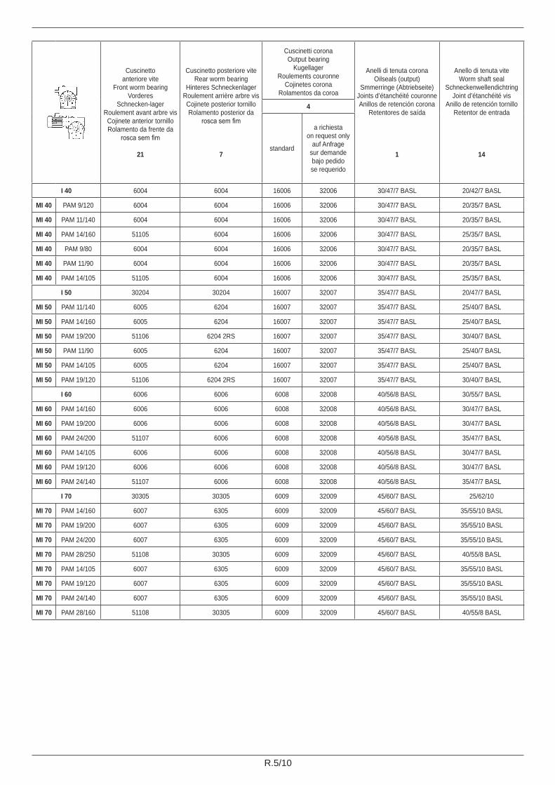
MI 40 ÷ 70
R.5/10
Cuscinettoanteriore vite
Front worm bearingVorderes
Schnecken-lagerRoulement avant arbre visCojinete anterior tornilloRolamento da frente da
rosca sem fim
21
Cuscinetto posteriore viteRear worm bearing
Hinteres SchneckenlagerRoulement arrière arbre visCojinete posterior tornilloRolamento posterior da
rosca sem fim
7
Cuscinetti coronaOutput bearing
KugellagerRoulements couronne
Cojinetes coronaRolamentos da coroa
Anelli di tenuta coronaOilseals (output)
Smmerringe (Abtriebseite)Joints d’étanchéité couronneAnillos de retención corona
Retentores de saída
1
Anello di tenuta viteWorm shaft seal
SchneckenwellendichtringJoint d’étanchéité vis
Anillo de retención tornilloRetentor de entrada
14
4
standard
a richiestaon request only
auf Anfragesur demandebajo pedidose requerido
I 40 6004 6004 16006 32006 30/47/7 BASL 20/42/7 BASL
MI 40 PAM 9/120 6004 6004 16006 32006 30/47/7 BASL 20/35/7 BASL
MI 40 PAM 11/140 6004 6004 16006 32006 30/47/7 BASL 20/35/7 BASL
MI 40 PAM 14/160 51105 6004 16006 32006 30/47/7 BASL 25/35/7 BASL
MI 40 PAM 9/80 6004 6004 16006 32006 30/47/7 BASL 20/35/7 BASL
MI 40 PAM 11/90 6004 6004 16006 32006 30/47/7 BASL 20/35/7 BASL
MI 40 PAM 14/105 51105 6004 16006 32006 30/47/7 BASL 25/35/7 BASL
I 50 30204 30204 16007 32007 35/47/7 BASL 20/47/7 BASL
MI 50 PAM 11/140 6005 6204 16007 32007 35/47/7 BASL 25/40/7 BASL
MI 50 PAM 14/160 6005 6204 16007 32007 35/47/7 BASL 25/40/7 BASL
MI 50 PAM 19/200 51106 6204 2RS 16007 32007 35/47/7 BASL 30/40/7 BASL
MI 50 PAM 11/90 6005 6204 16007 32007 35/47/7 BASL 25/40/7 BASL
MI 50 PAM 14/105 6005 6204 16007 32007 35/47/7 BASL 25/40/7 BASL
MI 50 PAM 19/120 51106 6204 2RS 16007 32007 35/47/7 BASL 30/40/7 BASL
I 60 6006 6006 6008 32008 40/56/8 BASL 30/55/7 BASL
MI 60 PAM 14/160 6006 6006 6008 32008 40/56/8 BASL 30/47/7 BASL
MI 60 PAM 19/200 6006 6006 6008 32008 40/56/8 BASL 30/47/7 BASL
MI 60 PAM 24/200 51107 6006 6008 32008 40/56/8 BASL 35/47/7 BASL
MI 60 PAM 14/105 6006 6006 6008 32008 40/56/8 BASL 30/47/7 BASL
MI 60 PAM 19/120 6006 6006 6008 32008 40/56/8 BASL 30/47/7 BASL
MI 60 PAM 24/140 51107 6006 6008 32008 40/56/8 BASL 35/47/7 BASL
I 70 30305 30305 6009 32009 45/60/7 BASL 25/62/10
MI 70 PAM 14/160 6007 6305 6009 32009 45/60/7 BASL 35/55/10 BASL
MI 70 PAM 19/200 6007 6305 6009 32009 45/60/7 BASL 35/55/10 BASL
MI 70 PAM 24/200 6007 6305 6009 32009 45/60/7 BASL 35/55/10 BASL
MI 70 PAM 28/250 51108 30305 6009 32009 45/60/7 BASL 40/55/8 BASL
MI 70 PAM 14/105 6007 6305 6009 32009 45/60/7 BASL 35/55/10 BASL
MI 70 PAM 19/120 6007 6305 6009 32009 45/60/7 BASL 35/55/10 BASL
MI 70 PAM 24/140 6007 6305 6009 32009 45/60/7 BASL 35/55/10 BASL
MI 70 PAM 28/160 51108 30305 6009 32009 45/60/7 BASL 40/55/8 BASL

R.6/10
I-MI 80 ÷ 175
Pos. Descrizione Description Beschreibung Description Descripción Descrição
1 ANELLO DI TENUTA SHAFT SEAL WELLENDICHTUNG JOINT D’ÉTANCHÉITÉ AN. DE RETENCIÓN RETENTOR
2 PIEDE FOOT FUSS PIED PIE PÉ
3 GUARNIZIONE USCITA OUTPUT GASKET ABTRIEBSGARNITUR GARNITURE SORTIE JUNT.ÁRB.LENTO JUNTA DE SAÍDA
4 CUSCINETTO BEARING LAGER ROULEMENT COJINETE ROLAMENTO
5 CAPPELLOTTO ENDCAP ENDHKAPPE CHAPEAU DE FERMETURE CUBIERTA CERRADA TAMPA FECHADA
6 CUSCINETTO BEARING LAGER ROULEMENT COJINETE ROLAMENTO
7 COPERCHIO APERTO OPEN COVER OFFENER DECKEL COUVERCLE OUVERT CUBIERTA ABIERTA TAMPA ABERTA
8 CORONA WORM WHEEL SCHNECKENRAD COURONNE HÉLICOÏDALE CORONA COROA
9 CORPO HOUSING GEHAEUSE CARCASSE CUERPO CARCAÇA
10 LINGUETTA KEY KEIL LANGUETTE LENGÜETA CHAVETA
11 ANELLO DI TENUTA SHAFT SEAL WELLENDICHTUNG JOINT D’ÉTANCHÉITÉ AN. DE RETENCIÓN RETENTOR
12 VITE T.E. HEXAGONAL HEAD SCREW SECHSKANTSCHRAUBE VIS TÊTE HÉXAGONALE TORNILLO T.E. PARAFUSO
13 VITE T.E. HEXAGONAL HEAD SCREW SECHSKANTSCHRAUBE VIS TÊTE HÉXAGONALE TORNILLO T.E. PARAFUSO
14 VITE SENZA FINE WORM SHAFT SCHNECKENWELLE VIS SANS FIN TORNILLO SINFÍN ROSCA SEM FIM
15 FLANGIA PIATTA FLAT FLANGE FLACHFLANSCH BRIDE PLATE BRIDA PLANA FLANGE FP
16 GUARNIZIONE ENTRATA INPUT GASKET ANTRIEBSGARNITUR GARNITURE ENTRÉE JUNTA JUNTA DE ENTRADA
17 DADO ESAGONALE HEXAGONAL NUT SECHSKANTMUTTER ÉCROU HÉXAGONAL TUERCA HEXAGONAL PORCA
18 FLANGIA FLANGE FLANSCH BRIDE BRIDA FLANGE
19 VITE T.E. HEXAGONAL HEAD SCREW SECHSKANTSCHRAUBE VIS TÊTE HÉXAGONALE TORNILLO T.E. PARAFUSO
20 VITE T.E. HEXAGONAL HEAD SCREW SECHSKANTSCHRAUBE VIS TÊTE HÉXAGONALE TORNILLO T.E. PARAFUSO
21 V.S.F PAM WORM SHAFT PAM SCHNECKENWELLE PAM VIS SANS FIN PAM T.S.F PAM ROSCA SEM FIM PAM

R.7/10
Cuscinetti / Bearings / Kugellager Roulements / Cojinetes / Rolamentos
Anelli di tenuta / Oilseals / SimmerringeJoints d’étanchéité / Anillos de retención /
Retentores
6 6C
4
11 1standard
a richiesta / on request onlyauf Anfrage / sur demandebajo pedido / se requerido
I 80 3030525/62/18.25
3030525/62/18.25
601050/80/16
32010X50/80/20 25/40/7 BASL 50/65/8 BASL
MI 80 32007X35/62/18
3030525/62/18.25
601050/80/16
32010X50/80/20 35/50/7 BASL 50/65/8 BASL
MI 80 PAM 100 6190840/62/12
630525/62/17
601050/80/16
32010X50/80/20 40/55/8 BASL 50/65/8 BASL
I 90 3030630/72/20.75
3030630/72/20.75
601155/90/18
32011X55/90/23 30/6010 55/72/10 BASL
MI 90 3020735/72/18.25
3030630/72/20.75
601155/90/18
32011X55/90/23 35/60/10 55/72/10 BASL
MI 90 PAM 112 32008X40/68/19
3030630/72/20.75
601155/90/18
32011X55/90/23 40/60/10 BASL 55/72/10 BASL
I 110 3030735/80/22.75
3030735/80/22.75
601260/95/18
32012X60/95/23 35/72/10 BASL 60/80/10 BASL
MI 110 3020840/80/19.75
3030735/80/22.75
601260/95/18
32012X60/95/23 40/60/10 BASL 60/80/10 BASL
MI 110 PAM 132 3301050/80/24
3030735/80/22.75
601260/95/18
32012X60/95/23 50/70/10 BASL 60/80/10 BASL
I-MI 130 3220945/85/24.75
3220945/85/24.75
601470/110/20
32014X70/110/25 45/72/10 70/90/10 BASL
MI 130 PAM 132 32011X55/90/23
3220945/85/24.75
601470/110/20
32014X70/110/25 55/80/10 BASL 70/90/10 BASL
I-MI 150 3021155/110/22.75
3021155/110/22.75
621680/140/26
3021680/140/28.25 55/80/10 BASL 80/100/10 BASL
I-MI 175 3021260/110/23.75
3021260/110/23.75
621785/150/28
3021785/150/30.5 60/80/10 BASL 85/110/13 BASL

R.8/10
U 30
MU 30

R.9/10
MU 40 - 110
Pos. Descrizione Description Beschreibung Description Descripción Descrição1 CARCASSA HOUSING GEHAEUSE CARCASSE CARCASA CAIXA2 COPERCHIO LATERALE SIDE COVER SEITLICHER DECKEL COUVERCLE LATÉRALE CUBIERTA LATERAL TAMPA LATERAL
3 CORONA WORMWHEEL SCHNECKENRAD COURONNE HELICOIDALE CORONA COROA
4 VITE SENZA FINE WORM SHAFT SCHNECKENWELLE VIS SANS FIN T.S.F. ROSCA SEM FIM
5 FLANGIA ATTACCO MOTORE
MOTOR CONNECTION FLANGE MOTORFLANSCH BRIDE ACCOUPLEMENT
MOTEUR BRIDA CONEXIÓN MOTOR FLANGE ACOPLAGEM MOTOR
6 DISTANZIALE SPACER DISTANZRING DISTANTIAL DISTANCIADOR ESPAÇADOR7 ANELLO SEEGER SNAP RING SEEGERRING ANNEAU D’ARRÊT ANILLO SEEGER ANEL ELÁSTICO8 BOCCOLA BUSHING BUCHSE DOUILLE CASQUILLO CASQUILHO9 GUARNIZIONE GASKET DICHTUNG GARNITURE JUNTA GUARNICAO10 “O” RING “O” RING “O” RING JOINT TORIQUE “OR” ANEL DE VEDAÇÃO “OR”11 ANELLO DI TENUTA OILSEALS SIMMERRINGE JOINT D’ÉTANCHÉITÉ ANILLO DE RETENCIÓN ANEL RETENTOR12 ANELLO SEEGER SNAP RING SEEGERRING ANNEAU D’ARRÊT ANILLO SEEGER ANEL ELÁSTICO13 CUSCINETTO BEARING LAGER ROULEMENT COJINETE MANCAL14 CUSCINETTO BEARING LAGER ROULEMENT COJINETE MANCAL15 “O” RING “O” RING “O” RING JOINT TORIQUE “OR” ANEL DE VEDAÇÃO “OR”16 CUSCINETTO BEARING LAGER ROULEMENT COJINETE MANCAL17 ANELLO DI TENUTA OILSEALS SIMMERRINGE JOINT D’ÉTANCHÉITÉ ANILLO DE RETENCIÓN ANEL RETENTOR18 VITI SCREWS SCHRAUBEN VIS TORNILLOS ROSCAS19 VITI SCREWS SCHRAUBEN VIS TORNILLOS ROSCAS
20 CAPPELLOTTO END COVER ENDKAPPE COUVERCLE DE FERMETURE CAPERUZA TAMPÃO
21 ANELLO DI TENUTA OILSEALS SIMMERRINGE JOINT D’ÉTANCHÉITÉ ANILLO DE RETENCIÓN ANEL RETENTOR22 ANELLO SEEGER SNAP RING SEEGERRING ANNEAU D’ARRÊT ANILLO SEEGER ANEL ELÁSTICO23 ANELLO SEEGER SNAP RING SEEGERRING ANNEAU D’ARRÊT ANILLO SEEGER ANEL ELÁSTICO24 VITI SCREWS SCHRAUBEN VIS TORNILLOS ROSCAS25 DADI NUTS MUTTERN ECROUS TUERCAS PORCAS26 LINGUETTA TAB LASCHE LANGUETTE LENGUETA LINGUETA27 DISTANZIALE SPACER DISTANZRING DISTANTIAL DISTANCIADOR ESPAÇADOR28 COPERCHIETTO COVER DECKEL COUVERCLE TAPA TAMPO
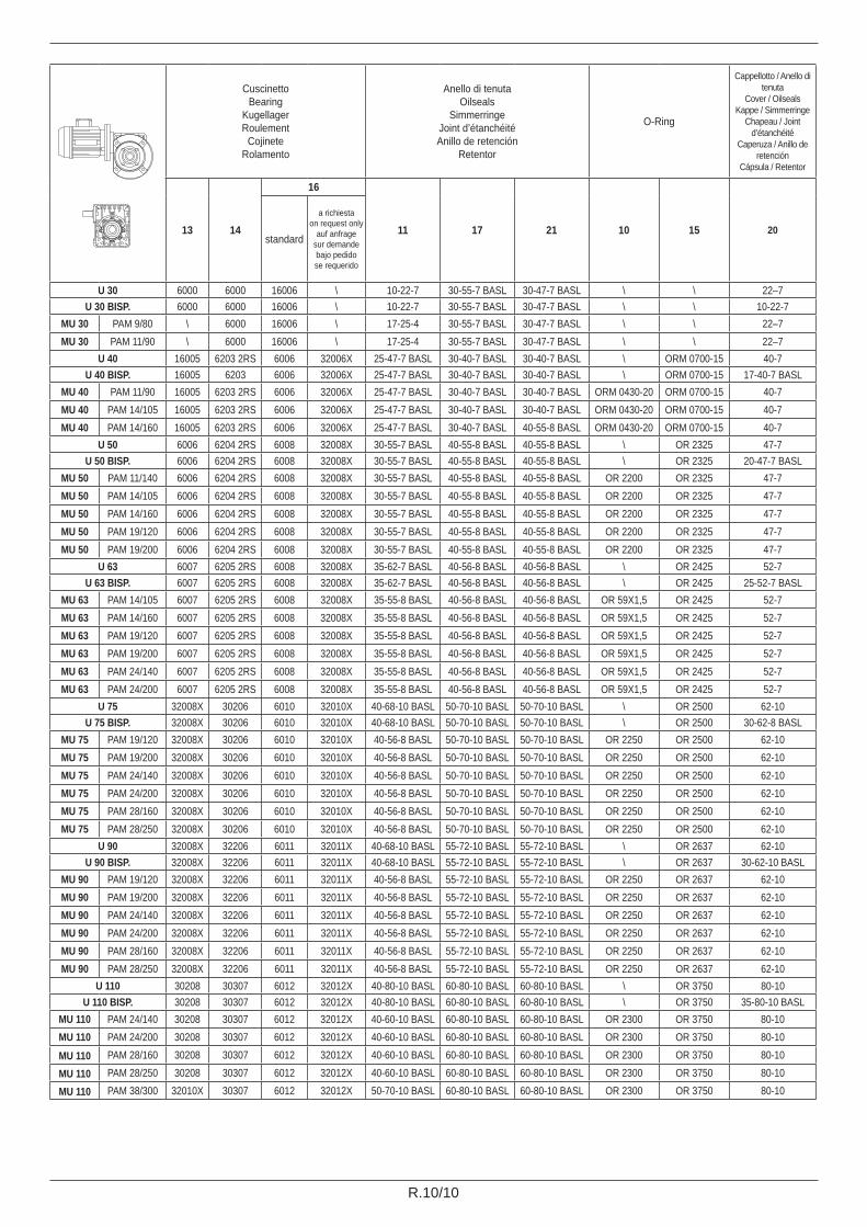
R.10/10
Cuscinetto Bearing
KugellagerRoulement
Cojinete Rolamento
Anello di tenuta Oilseals
SimmerringeJoint d’étanchéité Anillo de retención
Retentor
O-Ring
Cappellotto / Anello di tenuta
Cover / Oilseals Kappe / Simmerringe
Chapeau / Joint d’étanchéité
Caperuza / Anillo de retención
Cápsula / Retentor
13 14
16
11 17 21 10 15 20standard
a richiestaon request only
auf anfragesur demande bajo pedidose requerido
U 30 6000 6000 16006 \ 10-22-7 30-55-7 BASL 30-47-7 BASL \ \ 22–7U 30 BISP. 6000 6000 16006 \ 10-22-7 30-55-7 BASL 30-47-7 BASL \ \ 10-22-7
MU 30 PAM 9/80 \ 6000 16006 \ 17-25-4 30-55-7 BASL 30-47-7 BASL \ \ 22–7MU 30 PAM 11/90 \ 6000 16006 \ 17-25-4 30-55-7 BASL 30-47-7 BASL \ \ 22–7
U 40 16005 6203 2RS 6006 32006X 25-47-7 BASL 30-40-7 BASL 30-40-7 BASL \ ORM 0700-15 40-7U 40 BISP. 16005 6203 6006 32006X 25-47-7 BASL 30-40-7 BASL 30-40-7 BASL \ ORM 0700-15 17-40-7 BASL
MU 40 PAM 11/90 16005 6203 2RS 6006 32006X 25-47-7 BASL 30-40-7 BASL 30-40-7 BASL ORM 0430-20 ORM 0700-15 40-7MU 40 PAM 14/105 16005 6203 2RS 6006 32006X 25-47-7 BASL 30-40-7 BASL 30-40-7 BASL ORM 0430-20 ORM 0700-15 40-7MU 40 PAM 14/160 16005 6203 2RS 6006 32006X 25-47-7 BASL 30-40-7 BASL 40-55-8 BASL ORM 0430-20 ORM 0700-15 40-7
U 50 6006 6204 2RS 6008 32008X 30-55-7 BASL 40-55-8 BASL 40-55-8 BASL \ OR 2325 47-7U 50 BISP. 6006 6204 2RS 6008 32008X 30-55-7 BASL 40-55-8 BASL 40-55-8 BASL \ OR 2325 20-47-7 BASL
MU 50 PAM 11/140 6006 6204 2RS 6008 32008X 30-55-7 BASL 40-55-8 BASL 40-55-8 BASL OR 2200 OR 2325 47-7MU 50 PAM 14/105 6006 6204 2RS 6008 32008X 30-55-7 BASL 40-55-8 BASL 40-55-8 BASL OR 2200 OR 2325 47-7MU 50 PAM 14/160 6006 6204 2RS 6008 32008X 30-55-7 BASL 40-55-8 BASL 40-55-8 BASL OR 2200 OR 2325 47-7MU 50 PAM 19/120 6006 6204 2RS 6008 32008X 30-55-7 BASL 40-55-8 BASL 40-55-8 BASL OR 2200 OR 2325 47-7MU 50 PAM 19/200 6006 6204 2RS 6008 32008X 30-55-7 BASL 40-55-8 BASL 40-55-8 BASL OR 2200 OR 2325 47-7
U 63 6007 6205 2RS 6008 32008X 35-62-7 BASL 40-56-8 BASL 40-56-8 BASL \ OR 2425 52-7U 63 BISP. 6007 6205 2RS 6008 32008X 35-62-7 BASL 40-56-8 BASL 40-56-8 BASL \ OR 2425 25-52-7 BASL
MU 63 PAM 14/105 6007 6205 2RS 6008 32008X 35-55-8 BASL 40-56-8 BASL 40-56-8 BASL OR 59X1,5 OR 2425 52-7MU 63 PAM 14/160 6007 6205 2RS 6008 32008X 35-55-8 BASL 40-56-8 BASL 40-56-8 BASL OR 59X1,5 OR 2425 52-7MU 63 PAM 19/120 6007 6205 2RS 6008 32008X 35-55-8 BASL 40-56-8 BASL 40-56-8 BASL OR 59X1,5 OR 2425 52-7MU 63 PAM 19/200 6007 6205 2RS 6008 32008X 35-55-8 BASL 40-56-8 BASL 40-56-8 BASL OR 59X1,5 OR 2425 52-7MU 63 PAM 24/140 6007 6205 2RS 6008 32008X 35-55-8 BASL 40-56-8 BASL 40-56-8 BASL OR 59X1,5 OR 2425 52-7MU 63 PAM 24/200 6007 6205 2RS 6008 32008X 35-55-8 BASL 40-56-8 BASL 40-56-8 BASL OR 59X1,5 OR 2425 52-7
U 75 32008X 30206 6010 32010X 40-68-10 BASL 50-70-10 BASL 50-70-10 BASL \ OR 2500 62-10U 75 BISP. 32008X 30206 6010 32010X 40-68-10 BASL 50-70-10 BASL 50-70-10 BASL \ OR 2500 30-62-8 BASL
MU 75 PAM 19/120 32008X 30206 6010 32010X 40-56-8 BASL 50-70-10 BASL 50-70-10 BASL OR 2250 OR 2500 62-10MU 75 PAM 19/200 32008X 30206 6010 32010X 40-56-8 BASL 50-70-10 BASL 50-70-10 BASL OR 2250 OR 2500 62-10MU 75 PAM 24/140 32008X 30206 6010 32010X 40-56-8 BASL 50-70-10 BASL 50-70-10 BASL OR 2250 OR 2500 62-10MU 75 PAM 24/200 32008X 30206 6010 32010X 40-56-8 BASL 50-70-10 BASL 50-70-10 BASL OR 2250 OR 2500 62-10MU 75 PAM 28/160 32008X 30206 6010 32010X 40-56-8 BASL 50-70-10 BASL 50-70-10 BASL OR 2250 OR 2500 62-10MU 75 PAM 28/250 32008X 30206 6010 32010X 40-56-8 BASL 50-70-10 BASL 50-70-10 BASL OR 2250 OR 2500 62-10
U 90 32008X 32206 6011 32011X 40-68-10 BASL 55-72-10 BASL 55-72-10 BASL \ OR 2637 62-10U 90 BISP. 32008X 32206 6011 32011X 40-68-10 BASL 55-72-10 BASL 55-72-10 BASL \ OR 2637 30-62-10 BASL
MU 90 PAM 19/120 32008X 32206 6011 32011X 40-56-8 BASL 55-72-10 BASL 55-72-10 BASL OR 2250 OR 2637 62-10MU 90 PAM 19/200 32008X 32206 6011 32011X 40-56-8 BASL 55-72-10 BASL 55-72-10 BASL OR 2250 OR 2637 62-10MU 90 PAM 24/140 32008X 32206 6011 32011X 40-56-8 BASL 55-72-10 BASL 55-72-10 BASL OR 2250 OR 2637 62-10MU 90 PAM 24/200 32008X 32206 6011 32011X 40-56-8 BASL 55-72-10 BASL 55-72-10 BASL OR 2250 OR 2637 62-10MU 90 PAM 28/160 32008X 32206 6011 32011X 40-56-8 BASL 55-72-10 BASL 55-72-10 BASL OR 2250 OR 2637 62-10MU 90 PAM 28/250 32008X 32206 6011 32011X 40-56-8 BASL 55-72-10 BASL 55-72-10 BASL OR 2250 OR 2637 62-10
U 110 30208 30307 6012 32012X 40-80-10 BASL 60-80-10 BASL 60-80-10 BASL \ OR 3750 80-10U 110 BISP. 30208 30307 6012 32012X 40-80-10 BASL 60-80-10 BASL 60-80-10 BASL \ OR 3750 35-80-10 BASL
MU 110 PAM 24/140 30208 30307 6012 32012X 40-60-10 BASL 60-80-10 BASL 60-80-10 BASL OR 2300 OR 3750 80-10MU 110 PAM 24/200 30208 30307 6012 32012X 40-60-10 BASL 60-80-10 BASL 60-80-10 BASL OR 2300 OR 3750 80-10
MU 110 PAM 28/160 30208 30307 6012 32012X 40-60-10 BASL 60-80-10 BASL 60-80-10 BASL OR 2300 OR 3750 80-10
MU 110 PAM 28/250 30208 30307 6012 32012X 40-60-10 BASL 60-80-10 BASL 60-80-10 BASL OR 2300 OR 3750 80-10
MU 110 PAM 38/300 32010X 30307 6012 32012X 50-70-10 BASL 60-80-10 BASL 60-80-10 BASL OR 2300 OR 3750 80-10

MIB5 B51 B53 B52 V1 V3
FFBRFBM
FBML
STANDARD
FP
STANDARD
IB3 V5 B8 V6 B6 B7
A
STANDARD
B
STANDARD
V
STANDARD
U-MUB5 B51 B53
STANDARD
B8
B3
B6 B7
V5 V6
K
L
D
E
G IH
1
2
3
4
5
67
max 0,2-0,3
2
1
I 130 M10I 150 M12I 175 M12
°C
F
B CA

04.2018
ITALIA ITALYSEDE e STABILIMENTO HEADQUARTERSVia G. Di Vittorio, 440053 VALSAMOGGIA Loc. Monteveglio (Bo) - ItalyTel. +39/051/6714811 - Fax. +39/051/6714858E-mail: [email protected] [email protected] [email protected]: www.sitiriduttori.it
RIDUTTORIMOTORIDUTTORIVARIATORI CONTINUIMOTORI ELETTRICI C.A./C.C.GIUNTI ELASTICI
GEARBOXESGEARED MOTORSSPEED VARIATORSA.C./D.C. ELECTRIC MOTORSFLEXIBLE COUPLINGS
SPASOCIETÀ ITALIANA TRASMISSIONI INDUSTRIALI
®
SOCIETÀ ITALIANA TRASMISSIONI INDUSTRIALISPA
TM
MD
U-M
UI-M
I®
CINA CHINAShanghai SITI Power Transmission Co., Ltd. Block A, No.558 Xuan Qiu Rd. Sanzao Industrial Park,Pudong New Area, Shanghai, P.R.China P.C.:201300 Tel: +86-21-68060500 - Fax: +86-21-68122539 E-mail: [email protected]: www.sh-siti.com
POLONIA POLANDSITI-TECH Sp. z o.o.Milejowice, ul. Napêdowa 426-652 Zakrzew POLANDE-mail: [email protected]: www.sititech.pl
ROMANIA ROMANIAS.C. SITI BALKANIA SRLPiatra Craiului, 7 (Zona Ind. La Dibo) - Hala4 Comp.7 - Jud Prahova - RomaniaTel. +40-244434243 - Fax. +40-244434243E-mail: [email protected]: www.sitibalkania.ro
USASITI Power Transmission USA, Inc.37 Ayer Rd, Littleton, MA 01460Tel.: 978-339-4500 - Fax: 978-338-0800E-mail: [email protected]: www.sitipowertransmission.com
WORMGEARBOXES INSTRUCTION AND SPARE PARTS MANUAL
EN
1409
1 - w
ww
.ser
tek.
it