Embed Size (px)
Citation preview

Slag-Refractory Interactions
Brad Nielson, Larry L. Baxter
Date
i

Table of Contents
Table of Contents............................................................................................................... iiList of Figures.................................................................................................................... iiiList of Tables.....................................................................................................................iiiMajor Institutional Contributors........................................................................................1Gasification........................................................................................................................1Slag Composition and Properties.......................................................................................1
Coal...........................................................................................................................1Petcoke......................................................................................................................2Biomass.....................................................................................................................3
Experimental Systems........................................................................................................4Static Systems................................................................................................................5
Sessile Drop Test.......................................................................................................5Crucible Test..............................................................................................................5Immersion/Finger Test..............................................................................................5Induction Furnace Test..............................................................................................6
Dynamic Systems...........................................................................................................6
Rotating Finger Test..................................................................................................6Rotating Slag Test......................................................................................................6
Refractory Wear................................................................................................................7Chemical Corrosion.......................................................................................................7
Physical Wear................................................................................................................7
Spalling......................................................................................................................7Erosion......................................................................................................................8Creep.........................................................................................................................8
Chemical Dissolution..........................................................................................................9Mechanisms..................................................................................................................9
Thermodynamics.......................................................................................................9Transport Limitation..................................................................................................9
Specific Systems..........................................................................................................10
SiO2..........................................................................................................................10Al2O3........................................................................................................................11Cr2O3........................................................................................................................11MgO........................................................................................................................12SiC...........................................................................................................................12
Spalling............................................................................................................................13ii
Mechanisms.....................................................................................................................13Volumetric Expansion..............................................................................................13Volumetric Shrinkage..............................................................................................13Thermal...................................................................................................................14
Specific Systems..........................................................................................................14
Engineered Formulations.................................................................................................15Aurex 95P....................................................................................................................15
Low Cr/No Cr Refractory.............................................................................................15
Refractory designs (spiral vs circular)..........................................................................16
Material Properties............................................................................................................1Models...............................................................................................................................1
Ash Deposition..............................................................................................................1
Slag Interaction.............................................................................................................2
Literature Cited..................................................................................................................3
List of Figures
No table of figures entries found.
List of Tables
No table of figures entries found.
iii

(Repeat Title and Subtitle here but do not format them using Styles or they will appear again in
the Table of Contents)
Major Institutional Contributors
DOE –National Energy Technology Laboratory, Albany, OR
DOE –National Energy Technology Laboratory, Pittsburgh, PA
DOE – Argonne National Laboratory, Argonne, IL
Electric Power Research Institute , Palo Alto, CA
Department of Engineering Materials, University of Sheffield, Sheffield, United Kingdom
Sandia National Laboratories, Livermore, CA
Pacific Northwest National Laboratories, Richland, WA
Cooperative Research Centre for Coal in Sustainable Development, University of
Newcastle, Callaghan, Australia
Advanced Combustion Engineering Research Center, Brigham Young University, Provo,
UT
National Renewable Energy Laboratory, Golden, CO
Gasification
Gasification is a process whereby a carbon feedstock goes through incomplete combustion.
Coal, petcoke, or biomass is reacted with water and oxygen in a reducing environment, at temperatures
greater than 1200 °C and pressures up to 400 psi. These conditions reduce the carbon feedstock into
charcoal, which through a series of reactions is converted into Syngas, which is composed of carbon
4

monoxide, carbon dioxide, and hydrogen as well as traces of methane. Syngas can be burned as fuel, or
separated and used for fuel cells or chemical feedstocks. During gasification impurities in the feedstock
form a molten slag which flows down the walls of the gasification chamber into a quenching tank.
Refractory lines the inside walls of a gasifier, but needs to be replaced frequently due to corrosion and
spalling caused by slag. The cost of replacing refractory is the number one reason gasification is not used
for mainstream energy production.
Slag Composition and Properties
Coal
Coal is the most common carbon feedstock used in gasification, and has been the subject of
much research [1-9]. Coal is a cheap feedstock, and is easily pulverized for gasification. Impurities in coal
vary with the region from where the coal originated, but all coals contain many of the same impurities.
These are oxides of Si and Al, while minor impurities are oxides of Fe, Ca, Mg, and S (see table 1). These
oxides form an acidic slag that is corrosive to the refractory lining. The corrosive behavior of coal slag
causes the composition to change continuously. This occurs by the dissolution of Al2O3 and Cr2O3 into the
slag from the refractory, and removal of FeO from the slag by forming a Fe(Al, Cr) 2O4 spinel layer at the
refractory-slag interface. Changes in the slag composition also cause changes in the slag viscosity, and as
the viscosity increases so does the corrosion of the refractory. [2]
5

Weight PercentMaterial Max. Min. Avg. Std. dev.
SiO2 68.5 7.1 43.6 16.4Al2O3 38.6 4.1 25.2 10.2CaO 69.7 2.1 17.0 11.2MgO 45.1 0.5 5.8 6.6K2O 8.0 0.1 1.2 1.1
Na2O 6.5 0.3 0.9 0.6TiO2 3.7 0.4 1.4 0.8
Table 1: Mineral impurities found in over 300 US coal slag samples [10]
Petcoke
Petcoke, a carbonaceous product from the petroleum cracking process, can also be used as a
source of carbon for gasification. In general petcoke produces less ash than coal, which means less slag.
Petcoke slag is very similar to coal slag, containing all of the same inorganic impurities, with the addition
of Ni and V (see table 2). Corrosion/dissolution from petcoke slag is not significantly different than coal
slag.[11]
Weight PercentMaterial Max. Min. Avg. Std. dev.SiO2 18.9 3.1 14.1 8.7Al2O3 9.4 0.5 4.8 2.8Fe2O3 31.6 1.2 7.2 9.3CaO 11.9 2.0 5.4 3.8MgO 5.1 0.3 1.0 1.6K2O 0.7 0.3 0.5 0.4Na2O 2.3 0.1 0.8 0.8TiO2 0.6 0.2 0.3 0.2NiO 11.4 2.9 8.4 3.2V2O5 79.4 30.2 57.4 19.5Table 2: Mineral impurities found in nine petcoke slag samples [10].
6

Biomass
Biomass is defined as biological material from living or recently living organisms. It comes in
many different forms: agricultural waste, energy crops, industrial waste, municipal waste, etc. Biomass is
a very attractive form of carbon feedstock due low prices and high availabilities, but even more
important is that there is a net zero CO2 emission when burned. If a carbon capture process is used after
gasification, then there will actually be a net negative CO2 emission. The composition of biomass varies
very drastically [12-34], since it is such a broad classification. Most forms of biomass have very high
levels of alkali and alkaline earth metals, particularly Na, K, and Mg, which are volatized by the presence
of chlorine (see table 3). Other inorganic impurities include Ca, Si, P, and S. Biomass slag is similar to coal
slag in the fact that is corrodes and dissolves away the refractory material, but the presence of alkali
metals in combination with chlorine makes it significantly more corrosive. This is a problem with using
biomass as a fuel, it is cheap fuel and readily available, but it eats through refractory liners faster than
coal or petcoke.[17]
Property(Wt%)
MaterialRice Straw Wheat
StrawSwitch Grass
Sugar Cane Trash
Sugar Cane Bagasse
Douglas Fir Wood
% Cl (dry wt biomass)
0.7 2.0 0.1 0.2 0.03 0.01
% Ash (dry wt biomass)
19.5 13.0 9.0 5.0 2.4 0.5
Al2O3 1.4 2.5 4.5 - 17.7 2.8CaO 1.6 4.7 5.6 13.1 4.5 37.1
Fe2O3 0.7 1.0 2.0 1.7 14.1 4.2K2O 11.3 18.3 11.6 13.4 4.2 17.0
MgO 1.9 2.5 3.0 4.3 33 5.9
7

Na2O 1.9 10.5 0.6 0.3 0.8 3.2P2O5 2.7 1.5 4.5 2.3 2.7 1.9SiO2 74.3 35.8 65.2 57.4 46.6 12.3TiO2 0.02 0.2 0.2 - 2.6 0.1SO3 0.8 5.5 0.4 7.3 2.1 11.2
Unknown 3.4 17.6 2.3 0.3 1.4 4.4Table 3: Ash chemistry of some biomass feedstocks [10].
Experimental Systems
Lee et. al. [35] was referenced for each of the following descriptions of experimental systems.
Static Systems
Static slag-refractory experiments are flawed by designed, but still yield some useful
information. The most apparent flaw is that of a non-flowing, static slag. It is a poor model for what
occurs inside a gasifier, yet it is an easy way to observe basic slag-refractory interactions.
Sessile Drop Test
This test is performed by placing a shaped slag sample on a refractory sample and then heating
it to temperature. Once the temperature is reached it is kept constant, until the slag begins to wet and
react with the refractory. The test is used to measure surface and interface energies of the slag and
refractory. The problem with this test is that the slag quickly becomes saturated with reaction products,
as well as the absence of a temperature gradient through the refractory.
Crucible Test
The crucible test is done by first hollowing out a cavity in a refractory brick, followed by filling
the cavity with slag and heating to a fixed temperature for a period of time. This test suffers from the
8

same problems as the sessile drop test, but is popular for testing new refractory samples because many
samples can easily be tested in a short amount of time.
Immersion/Finger Test
The immersion test is done by immersing a refractory sample in a vat of hot slag, for a fixed
amount of time. This technique minimizes the issue of the slag becoming saturated by keeping the ratio
of slag to refractory very high, but still has no temperature gradient.
Induction Furnace Test
In the induction furnace test an induction furnace is lined with refractory to form a crucible,
with is filled with slag and metal (for conduction), and heated to a fixed temperature and a period of
time. The use of an induction furnace creates a temperature gradient, as well as simulating slight slag
flow. This occurs because the less dense slag floats to the top of the crucible, cause a slight swirling
effect. This is by far the best static slag test, but is still far from actual operational conditions.
Dynamic Systems
Dynamic slag-refractory techniques are a far better simulation than static tests, for the simple
reason that the slag moves relative to the refractory. The flow of slag is crucial in removing boundary
layers, and speeding up the active corrosion process. Despite this, dynamic techniques still fall short of
actual conditions. The problem is that no technique to date uses a renewing slag, therefore the slag
becomes saturated and the corrosion processes slows.
Rotating Finger Test
The rotating finger test is very similar to the immersion test the only difference is that the
refractory sample spins around inside the vat of slag. This is a simple test that simulates flow well,
9

allowing for more accurate determination of the speed and depth of slag penetration, as well as
corrosion.
Rotating Slag Test
In the rotating slag test a cylindrical drum is lined with refractory, which is rotated about its
horizontal axis. While the drum is rotating, slag is melted inside with a torch. This creates a temperature
gradient in addition to flowing slag. On top of all of that the drum can periodically be tilted to drain the
slag, so that it can be replaced with fresh slag. This by far the best and most popular technique, which
also allows testing of many refractory samples at once, but it still has a few downfalls. First off the slag
renewal isn’t continuous, secondly the temperature is difficult to keep constant, and finally the results
are very irreproducible.
Refractory Wear
Chemical Corrosion
Chemical corrosion is defined by Brosnan [36] as “refractory wear by loss of thickness and mass
from the exposed face of the refractory as a consequence of chemical attack by a corroding fluid in a
process in which the refractory and the corroding fluid react approaching chemical equilibrium in the
zone of contact between the refractory and the fluid.” This broad definition encompasses a number of
slag-refractory interactions, which include: dissolution, formation of new phases and solid solutions, as
well as precipitation onto the refractory, with dissolution being the most prominent. Corrosion has
been a topic of much research, [36-88] causing it to be a well understood process and therefore very
predictable.
10

Physical Wear
A majority of refractory wear can be attributed to physical wear, most specifically due to the
process of spalling. Other forms of physical wear include erosion, creep, and thermal shock.
Spalling
Spalling is the irregular breaking away of large chunks of refractory material, which occurs when
multiple subsurface cracks come together. Spalling causes rapid and uneven refractory wear, at rates
much faster than by corrosion. The irregularity and randomness of spalling make it very difficult to
model. According to Bennett [89] “Spalling may be initiated by many causes. Slag penetration and
interactions between the slag and the refractory form new phases with different thermal expansion that
could lead to crack formation and stresses. Once slag has penetrated a refractory surface,
density/expansion differences between the penetrated/non-penetrated refractory also exist that could
lead to crack formation and spalling. Spalling may also be influenced by iron compounds that interact in
the slag/refractory, forming spinel or solid solution phases with an expansion behavior different in the
refractory or that may change with the oxidizing/reducing state of the gasifier. Other operational
practices, like depressurization of the gasifier while the hot face is at or near operating temperature,
rapid or uncontrolled gasifier shutdown, oxidizing preheats/shutdowns of the gasifier, gasification vessel
design/construction, refractory creep, or thermal cycling of the gasifier could be additional causes or
contributing factors to hot face spalling.”
Erosion
Erosion is the abrasive removal of refractory material [59, 63, 66, 78, 80, 81, 83, 90-94]. Erosion
causes refractory material to be lost at slow, but constant rate. Eroded refractory has the same
appearance as corroded refractory, with the exception that it doesn’t occur evenly. There are high
11

erosion areas, while most experience very little erosion. Erosion is caused by high velocity particulates in
the fuel/water slurry, which slowly wears down the refractory by the continual flow of the slurry over
the face of the refractory, much like a rock being polished in a stream. The constant flow of slag down
the gasifier walls also causes erosion, but to a lesser extent.
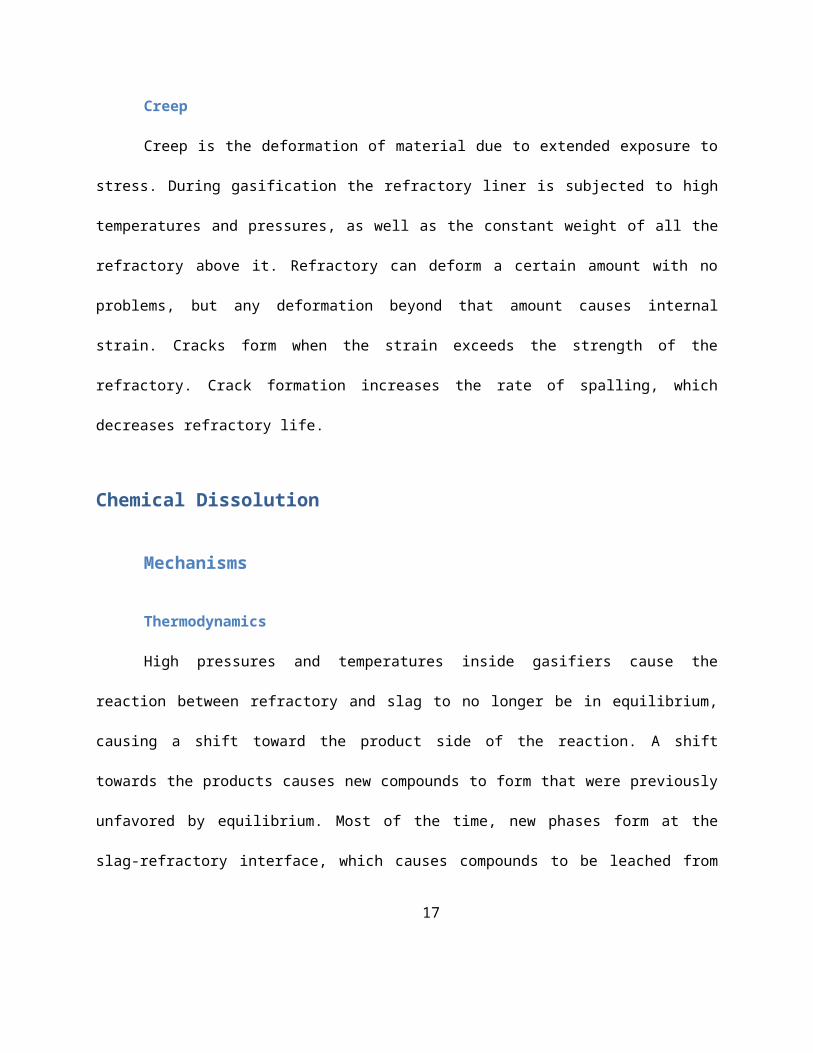
Creep
Creep is the deformation of material due to extended exposure to stress. During gasification the
refractory liner is subjected to high temperatures and pressures, as well as the constant weight of all the
refractory above it. Refractory can deform a certain amount with no problems, but any deformation
beyond that amount causes internal strain. Cracks form when the strain exceeds the strength of the
refractory. Crack formation increases the rate of spalling, which decreases refractory life.
Chemical Dissolution
Mechanisms
Thermodynamics
High pressures and temperatures inside gasifiers cause the reaction between refractory and slag
to no longer be in equilibrium, causing a shift toward the product side of the reaction. A shift towards
the products causes new compounds to form that were previously unfavored by equilibrium. Most of
the time, new phases form at the slag-refractory interface, which causes compounds to be leached from
the refractory as well as the slag. While some new phases limit slag penetration, others do not, but
ultimately all weaken refractory bonding. It is also common for compounds in the refractory to be
soluble in the slag, as well as components in the slag to precipitate onto the refractory. Fortunately this
12

dissolution effect decreases with distance from the hot-face of the refractory. This occurs because of the
temperature gradient in the refractory, which causes there to be different equilibrium conditions from
the hot face to the cold face [95]. Much work has been done to create thermodynamic models to be
able to predict slag-refractory interactions [39, 40, 95-114].
Transport Limitation
Slag can only corrode refractory material so far as it is able to come into contact with it,
therefore if slag-refractory contact can be limited then so will corrosion. Obviously there is no way to
protect the hot-face of the refractory, expect with chemical inertness, but many refractories
compositions form new chemical phases at the slag-refractory interface, which act as a barrier between
the slag and refractory by slowing transport of the slag. Once slag is through the new phase it begins to
penetrate into the refractory, dissolving refractory and/or forming new compounds with the refractory.
Diffusion of dissolved refractory through new phases into the slag is the major factor in the rate of
corrosion [115]. Porosity in refractory increases the rate of corrosion by providing channels for slag to
flow in, allowing deep penetration to be reached quickly [116]. Unfortunately current manufacturing
processes of refractory make it impossible to completely eliminate porosity, but reductions in porosity
limit speed and depth of slag penetration [7, 47, 86, 115, 117-120], translating to increased refractory
life. The only downside in reducing porosity is that the denser the refractory becomes the quicker it
fractures dues to internal strains caused by volumetric expansion.
13

Specific Systems
SiO2
Due to its poor corrosion resistance silica refractory is only used as an insulating layer, where it
is not in direct contact with slag. Silica’s high corrosion rate occurs because it is leached from the
refractory by hydrogen gas, which is a product of gasification. In this leaching process, silica reacts with
hydrogen to form water and SiO, which escapes as a gas. The reaction only proceeds with temperatures
greater than 1200 °C and in the absence of water. In the presence of water this reaction doesn’t occur,
but a different reaction occurs with steam. Steam will dissolve and/or distill silica forming products such
as H2SiO4 [121]. Unfortunately even as insulating layer, silica will still corrode, because hydrogen and
steam will penetrate the hot face and backup refractories through seams and cracks. When the
insulating refractory layer corrodes and becomes thin it causes hot spots to form on the outer shell of
the gasifier.
Al2O3
Alumina refractory has been used for many years, and traditionally has been known as a very
chemically resistant material. In the past few decades its use has declined, but is still a topic of research
[4, 56, 64, 65, 121-125]. Like all refractory systems, corrosion resistance depends on the composition of
the slag. In the absence of FeOx and at temperatures below 1200 °C the corrosion of Alumina is minimal.
This occurs because the ‘low’ temperature and absence of FeO x cause the slag viscosity to be high, and
the saturation of alumina to be low, which is reached quickly because slag already contains a fair
amount of alumina. Iron in the slag causes the viscosity to decrease as well as catalyzing the formation
of a CaAl2Si2O8 phase at the slag-refractory interface. The formation of a new phase slows the slag
14

penetration, but also changes the equilibrium conditions, causing more alumina to dissolve out of the
refractory [125].
Cr2O3
In the mid 70’s to early 80’s refractory research concluded that ≥75% chromia content is
required to withstand extreme gasification conditions [3, 89, 96, 114, 117, 119, 126-149]. When coal
slag and high chromia refractory interact, iron oxide in the slag reacts with chromia to form an iron-
chromium spinel. This essentially removes all the iron oxide from the slag, while the remaining oxides of
calcium, aluminum, and silicon penetrate deep into the refractory, as they don’t react with the chromia
particles. Work done by Kowng [11], suggests that the iron-chromia spinel impedes the diffusion of
alumina from the refractory and iron into the refractory. The constant flow of slag causes the spinel
layer to keep growing. This constant growth of the spinel layer causes volume changes in the refractory,
which results in microcracking, ultimately causing chemical spalling.
The use of petcoke as a feedstock causes different slag-refractory interactions, due to the
presence of vanadium in the slag. The vanadium causes a nonstoichiometric iron-vanadium-chromium-
aluminum solid solution to form, opposed to the iron-chromium spinel that forms when coal is used.
This solid solution accommodates large amounts of iron, vanadium, and aluminum, causing an even
greater volume change than the iron-chromium spinel, resulting in increased chemical spalling [11].
MgO
While not used much anymore, magnesia refractory worked well before the development of
high chromia refractory [56, 85-87, 102, 146, 150-153]. Sintered and fused magnesia refractory
materials exhibit good corrosion resistance. Upon interaction with slag, iron and manganese ions from
the slag will react with the magnesia in the refractory to form magnesiowustite, (Mg, Fe)O. The
15

magnesiowustite layer decreases the depth of slag penetration by depleting the slag of iron, causing it to
be less viscous. Depending on the composition of the slag, magnesiowustite can react with Ca and Si
ions in the slag to form new low melting phases, which are dissolved in the slag. This acts as a form of
indirect dissolution of MgO, meaning that its corrosion resistance is dependent on the carbon feedstock
used [153].
SiC
In the past decade there has been interest in use of SiC refractory [56, 72, 73, 154-159]. SiC
refractory withstands corrosion well, but has fallen short of surpassing the slag resistance of high
chromia refractory. The corrosion of SiC refractory is characterized by several different mechanisms. The
protective layer of SiO2 is dissolved by any CaO in the slag, forming calcium silicate compounds. This is
followed by iron dissolving SiC refractory grains, forming iron silcide compounds. In addition to all of
this, certain slags will dissolve the refractory binder, causing the refractory grains to break away with the
flow of slag [72].
Spalling
Mechanisms
Volumetric Expansion
Williford et. al. [160] define volumetric expansion as “compressive stresses in the plane of the
refractory surface, which lead to sub-surface cracking, and the eventual formation of a ‘blister’
configuration that spalls”. Volumetric expansion occurs when corrosion products are less dense than the
refractory. This decrease in density causes expansion to occur because the same amount of mass now
16
takes up more volume. An expansion causes there to be an increased amount of mass jammed into the
same volume, which causes internal stresses throughout the refractory. As these stresses grow they
eventually overcome the strength of the refractory, which causes cracks to form to relieve the stress. In
time, as these cracks grow and meet up with other cracks it causes large chunks of refractory to break
off, or spall. Volumetric expansion also occurs due to thermal expansion [161].
Volumetric Shrinkage
When volumetric shrinkage occurs it causes tensile stresses in the plane of the refractory.
Tensile stresses occur when volatile species are lost from the refractory matrix through interactions with
slag, which results in an increase in density. Over time these tensile stresses build up, and eventually
cause a system of cracks to form, “resembling a dried up river bed” [160]. These cracks slowly increase
in size and join up with each other, eventually causing large pieces of refractory to break off.
Thermal
Thermal shock is an effect that causes refractory to crack when exposed to rapid temperature
changes. Cracking occurs when a thermal gradient is present in the refractory, causing expansion at
different locations to occur at different rates. When a refractory brick expands at differential rates it
causes internal strain, which eventually overcomes the strength of the refractory, causing the formation
of internal cracks. As cracks expand and new ones form it causes the rate of spalling to increase. The
effects of thermal shock are made worse by low thermal conductivity and high thermal expansion
coefficients. Thermal shock occurs most often during rapid gasifier startups and shutdowns.
17

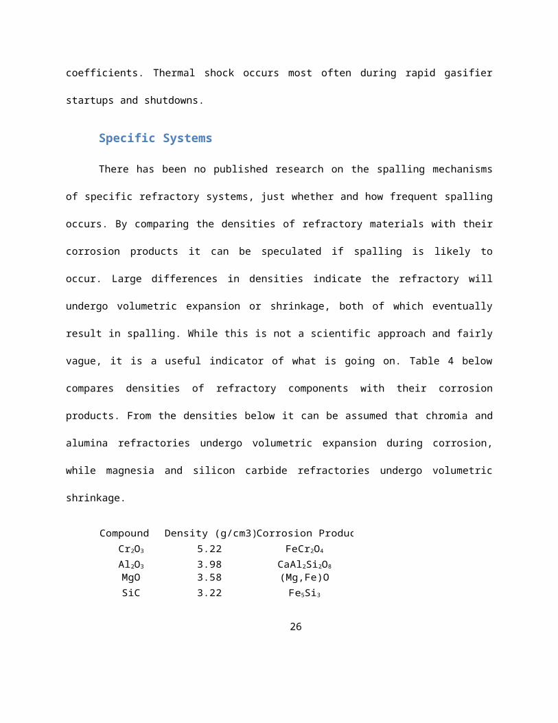
Specific Systems
There has been no published research on the spalling mechanisms of specific refractory systems,
just whether and how frequent spalling occurs. By comparing the densities of refractory materials with
their corrosion products it can be speculated if spalling is likely to occur. Large differences in densities
indicate the refractory will undergo volumetric expansion or shrinkage, both of which eventually result
in spalling. While this is not a scientific approach and fairly vague, it is a useful indicator of what is going
on. Table 4 below compares densities of refractory components with their corrosion products. From the
densities below it can be assumed that chromia and alumina refractories undergo volumetric expansion
during corrosion, while magnesia and silicon carbide refractories undergo volumetric shrinkage.
Compound Density (g/cm3) Corrosion Product Density (g/cm3)
5.22 4.5-4.8
3.98 2.765MgO 3.58 (Mg,Fe)O 3.58-6.0
SiC 3.22 up to 6.48
Cr2O3 FeCr2O4
Al2O3 CaAl2Si2O8
Fe5Si3
Table 4: Densities of refractory components and their corrosion products
Engineered Formulations
Aurex 95P
The National Energy Technology Laboratory in Albany, Oregon has developed and
patented a new high chrome refractory formulation, Aurex 95P, with phosphate additives for the
purpose of extending refractory life by eliminating structural and chemical spalling [11, 162-169].
Laboratory and field test results have shown that this new refractory formulation has improved slag
penetration resistance, improved thermal shock resistance, as well as comparable slag corrosive wear
18

resistance. Laboratory investigations [163] have indicated that possible mechanisms through which
phosphate additives improve the refractory performance are as follows: 1) phosphate additions
decrease porosity, contributing to a decrease in slag penetration; 2) phosphates promote the formation
of a dense Cr2O3-FeO spinel solid solution layer at the refractory/slag interface that inhibits slag
penetration; 3) phosphate additions promote the formation of an immiscible Ca 3(PO4)2 phase in the slag,
increasing slag viscosity and decreasing slag corrosivity; and 4) phosphates promote the formation of
lower melting bond phases that aid in thermal shock resistance. The development of Aurex 95P has
been a huge step forward toward making gasification a viable option for energy production.
Low Cr/No Cr Refractory
In recent years there has been a push for development of low chromium or chromium free
refractory materials [165, 167, 170-173]. The drive for this research has been motivated by: 1) current
high chromium refractories do not meet performance requirements of gasifier users 2) possible long
term health concerns associated with formation of hexavalent chromium 3) the high cost of chromium
4) the difficulty of sintering high chromium materials 5) the possibility of long term supply issues of
chromium [170]. While this is topic of much research, unfortunately there have been no published
findings of successful formulations.
The formation of hexavalent chromium from high chromium refractory is a safety concern
because hexavalent chromium containing compounds are carcinogenic [10, 96, 174]. This concern
originates from the cement and glass industries, in which hexavalent chrome compounds are formed
when high chrome refractories are used. Hexavalent chromium compounds are formed when high
chrome refractory interacts with alkali and alkaline earth metals, in an oxidizing environment. Gasifiers
operate under reducing conditions, under which hexavalent chrome production has yet to be observed,
19

but concern still exists because there may be possible conditions under which it could form during
gasification. Ultimately there isn’t enough information or research done to know whether or not it could
ever be a problem.
Refractory designs (spiral vs circular)
Refractory is almost always installed in a circular pattern around the inside of gasification
chambers, which makes it easy to install but creates problems later on. When refractory bricks undergo
expansion it causes each brick to push against its two neighbors, causing them to push on their
neighbors, ultimately forming a large ‘hoop’ stress all the way around the gasifier. As refractory
continues to expand these ‘hoop’ stresses increase until the stress is great enough that it causes the
refractory to crack and spall, which is the only form of relief. This problem has been identified, and
attempts to compensate for it have been made. Several gasification plants in China have experimented
with installing the refractory liner in a spiral pattern, therefore allowing refractory to shift as expansion
occurs. No results have been published, but initial reports indicate a significant decrease in the rate of
spalling, translating into an increase in refractory life.
20

Material Properties
Weight Percent Rotary Slag Test *3
A 92 4.7 3.3 4.2 12.7 63.1 +0.11 -0.24 +6.5 1.8B 95.1 4.3 4.27 14.8 65.5 +0.64 +0.18 +2.3 3.5C 87 3 6.5 4.07 16.5 66.9 -0.08 -1.98 +2.3 6.0D 94.5 3.2 20.0E 78.1 20 1 14.9 *1= 1550ºC, 50 hr holdF 94 6 4.25 14 125.3 14.6 *2 = 1550ºC, 50 psi, 50 hr holdG 91 6 3 4.18 16 115.3 12.8 *3 = 1667ºC, 5 hrs of slag feed, 2 ½ rpmH 88 6 6 4.14 17 101.0 9.2I 85 6 9 4.12 18 114.0 12.8
I 82 6 12 4.1 20 126.4 21.1 Creep Ratio *5J 61.78 16.24 11.48 6.28 0.79 0.22 3.9 9 202.4 9.9 2 0.586K 80.56 8.26 4.42 3.21 1.22 0.22 3.95 13 123.2 9.9 1 0.417L 87.29 3.46 6.02 0.6 1.38 0.15 4.23 15 118.2 13.2 16 0.837
*4 = 1100 °C - water cooling (cycles)*5 = under 0.2 Mpa, 1500 °C, 30h (%)
Bulk Density (g/cc)
Apparent Porosity
(%)
Reheat Expansion
*1
Creep Deformation
*2C2O3 Al2O3 ZrO2 SiO2 TiO2 Fe2O3 P2O5
CCS (MPa)
CMR (MPa)
-% area change
-mm penetration
Thermal Shock
Resistance *4
Table
5: Properties of some refractory materials21

List of some Refractory Manufactures Allied Mineral Products, Inc. Alsey Refractories Company American Precast Refractories, Inc. ANH Refractories Company B & B Refractories, Inc. BNZ Materials, Inc. Christy Refractories Company, L.L.C. Clayburn Industrial Group Ltd. Cometals Krosaki USA, Inc. LWB Refractories Matrix Refractories Division MINTEQ® INTERNATIONAL INC. Missouri Refractories New Castle Refractories Company
The Nock and Son Company RATH USA Refractarios Peruanos S. A. Resco Products, Inc. Ribbon Technology Corporation Rio Tinto Alcan Specialty Aluminas Riverside Refractories, Inc. Saint-Gobain Ceramic Materials Thermal Ceramics Thermal Ceramics Inc. Unifrax Corporation United Refractories Wahl Refractories, Inc. Whetstone Technology Whitacre Greer Company
Models
Ash Deposition
Ash deposition doesn’t occur during the gasification process because operating temperatures
are higher than the ash fusing temperature, but it is a continual problem in boilers. Inorganic impurities
in coal, petcoke, or biomass are unreactive during combustion and form deposits on the inside of
boilers, which cause problems if allowed to grow to sufficient size. Ash deposits cause reductions in heat
transfer, impedance of gas flow, as well as corrosion and erosion of the inside of boilers. The side effects
of ash deposition result in decreases in boiler efficiency, as well as unplanned shutdowns to replace
damaged refractory or pressure parts. Through the use of ash deposition models [14, 34, 80, 81, 92, 113,
175-209] boiler operators can predict ash deposition rates for their boiler, so that they know how often
ash needs to be cleaned out to be able to prevent shutdowns and run at maximum efficiency.

Slag Interaction
The operating temperatures during gasification are above ash fusion temperatures, therefore all
the inorganic feedstock impurities are turned into a molten slag. As mentioned earlier, slag is very
corrosive and destructive towards the refractory liners used in gasification chambers. Through continual
exposure to slag, refractory wears thin and becomes unable to insulate the exterior walls of the
gasification chamber from the high internal temperatures. As the exterior temperature of the
gasification chamber rises there becomes an increasing risk of the chamber rupturing, causing extremely
hot and corrosive gas to spew out at high velocity. Since frequent visual inspection of refractory liners is
not practical, slag models [30, 35, 51, 52, 95, 98, 100, 101, 103, 105, 108-111, 120, 150, 160, 161, 181,
183, 187, 188, 210-244] have been created to predict the rate of refractory wear. There are many
variables that factor into the rate at which refractory wears, the most important ones being: refractory
composition, refractory position in the gasifier, feedstock composition, temperature, and pressure. Since
there are so many variables involved in predicting refractory wear, it is unsafe for refractory operators
to rely only on their personal experience to know when the refractory liner needs to be replaced.
23

Literature Cited
1. Bakker, W.T., S.L. Darling, and W.C. Coons. REFRACTORY AND COAL SLAG EXPERIENCE IN THE COMBUSTION ENGINEERING GASIFICATION PROCESS DEVELOPMENT UNIT. in Annual Conference on Materials for Coal Conversion and Utilization. 1982. Palo Alto, CA USA.
2. Bakker, W.T., S.L. Darling, and W.C. Coons, Behavior of Coal Slag During Gasification. American Ceramic Society Bulletin, 1983. 62(12): p. 1359-1363.
3. Boow, J., Desirable physical and chemical properties of refractoris resistant to corrosion by coal-ash slags. Journal of the Australian Ceramic Society, 1969. 5(2): p. 45-54.
4. Ferber, M.K. and V.J. Tennery, BEHAVIOR OF TUBULAR CERAMIC HEAT-EXCHANGER MATERIALS IN ACIDIC COAL ASH FROM COAL-OIL-MIXTURE COMBUSTION. American Ceramic Society Bulletin, 1983. 62(2): p. 236-243.
5. He, J.-Q., et al., Slagging characteristics on refractory materials during pulverized-coal combusting. Journal of the China Coal Society, 2009. 34(5): p. 692-696.
6. He, J.-Q., et al., Slagging characteristics of molten ash on corundum during pulverized coal combustion. The Chinese Journal of Process Engineering, 2008. 8(4): p. 756-760.
7. Matyas, J., et al. Slag penetration into refractory lining of slagging coal gasifier. in International Pittsburgh Coal Conference. 2008. Pittsburgh: Pittsburgh Coal Conference, University of Pittsburgh.
8. Nakano, J., et al., Crystallization of Synthetic Coal-Petcoke Slag Mixtures Simulating Those Encountered in Entrained Bed Slagging Gasifiers. Energy & Fuels, 2009. 23: p. 4723-4733.
9. Su, S., J.H. Pohl, and D. Holcombe, Fouling propensities of blended coals in pulverized coal-fired power station boilers. Fuel, 2003. 82(13): p. 1653-1667.
10. Bennett, J.P., et al. Interactions between slag and high chrome oxide refractory liners in air cooled slagging gasifiers. in International Pittsburgh Coal Conference. 2008. Pittsburgh, PA: Pittsburgh Coal Conference, University of Pittsburgh,.
11. Kwong, K.-S., et al., Wear Mechanisms of Chromia Refractories in Slagging Gasifiers. International Journal of Applied Ceramic Technologies, 2007. 4(6): p. 503-513.
12. Arvelakis, S., et al., Effect of leaching on the ash behavior of olive residue during fluidized bed gasification. Biomass & Bioenergy, 2002. 22(1): p. 55-69.
13. Arvelakis, S. and E.G. Koukios, Physicochemical upgrading of agroresidues as feedstocks for energy production via thermochemical conversion methods. Biomass & Bioenergy, 2002. 22(5): p. 331-348.
14. Bakker, R.R., et al. Boiler Performance and Furnace Deposition During a Full Scale Test with Leached Biomass. in 3rd Biomass Conference of the Americas. 1997. Montreal, Ontario, Canada: Elsevier Science Limited
15. Dayton, D.C., R.J. French, and T.A. Milne, DIRECT OBSERVATION OF ALKALI VAPOR RELEASE DURING BIOMASS COMBUSTION AND GASIFICATION .1. APPLICATION OF MOLECULAR-BEAM MASS-SPECTROMETRY TO SWITCHGRASS COMBUSTION. Energy & Fuels, 1995. 9(5): p. 855-865.
16. Dayton, D.C., et al., Release of inorganic constituents from leached biomass during thermal conversion. Energy & Fuels, 1999. 13(4): p. 860-870.
17. Demirbas, A., Combustion of biomass. Energy Sources Part a-Recovery Utilization and Environmental Effects, 2007. 29(6): p. 549-561.
18. Heinzel, T., et al., Investifation of Slagging in Pulverized Fuel Co-combustion of Biomass and Coal at a Pilot-scale test facility. Fuel Processing Technology, 1998. 54: p. 109-125.

19. Jenkins, B.M., et al. Measurements of the Fouling and Slagging Characteristics of Banagrass (Pennisetum purpureum) Following Aqueous Extraction of Inorganic Constituents . in 3rd Biomass Conference of the Americas. 1997. Montreal, Ontario, Canada: Elsevier Science Limited.
20. Jenkins, B.M., et al. Combustion Properties of Biomass. in Engineering Foundation Conference on Industrial and Utility Use of Biomass. 1996. Snowbird, UT.
21. Jenkins, B.M., L.L. Baxter, and T.R. Miles, Combustion properties of biomass. Fuel Processing Technology, 1998. 54(1-3): p. 17-46.
22. Jenkins, B.M., et al., Combustion of residual biosolids from a high solids anaerobic digestion aerobic composting process. Biomass & Bioenergy, 1997. 12(5): p. 367-381.
23. Jensen, P.A., M. Stenholm, and P. Hald, Deposition Investigation in Straw-Fired Boilers. Energy and Fuels, 1997. 11: p. 1048-1055.
24. Miles, T.R. Operating Experience with Ash Deposition in Biomass Combustion Systems. in Biomass Combustion Conference. 1992. Reno, NV.
25. Miles, T.R., et al., Alkali deposits found in biomass power plants: A preliminary investigation of their extent and nature. 1995, United States. p. 135p.
26. Miles, T.R., et al., Boiler deposits from firing biomass fuels. Biomass & Bioenergy, 1996. 10(2-3): p. 125-138.
27. Miles, T.R. and T.R. Miles, Jr. Alkali Deposits in Biomass Power Plant Boilers. in Biomass Power Program. 1993. Washington D.C.
28. Miles, T.R., et al. Alkali Slagging Problems with Biomass Fuels. in First Biomass Conference of the Americas: Energy, Enviroment, Agriculture, and Industry. 1993. Burlington, VT: National Renewable Energy Laboratory.
29. Miller, B. and K. Deonarine, CHEMICAL TREATMENT OF BLACK LIQUOR RECOVERY BOILERS. American Society of Mechanical Engineers, Materials Properties Council - MPC, 1980: p. 7-15.
30. Mueller, C., et al. CFD based ash deposition prediction in a BFB firing mixtures of peat and forest residue. 2003. Jacksonville, FL: American Society of Mechanical Engineers.
31. Pronobis, M., Evaluation of the influence of biomass co-combustion on boiler furnace slagging by means of fusibility correlations. Biomass & Bioenergy, 2005. 28(4): p. 375-383.
32. Vamvuka, D. and D. Zografos, Predicting the behaviour of ash from agricultural wastes during combustion. Fuel, 2004. 83(14-15): p. 2051-2057.
33. Wang, F.-Y., et al., Burning and clinkering properties of black liquor coal water slurry in 0.25 MW furnace. Zhongguo Kuangye Daxue Xuebao/Journal of China University of Mining and Technology, 2004. 33(6): p. 726-730.
34. Yin, C., L.A. Rosendahl, and S.K. Kaer, Grate-firing of biomass for heat and power production. Progress in Energy and Combustion Science, 2008. 34(6): p. 725-754.
35. Lee, W.E. and S. Zhang, Melt corrosion of oxide and oxide-carbon refractories. International Materials Reviews, 1999. 44(3): p. 77-104.
36. Brosnan, D.A., Corrosion of refractories. Mechanical Engineering (Marcel Dekker), 2004. 178(Refractories Handbook): p. 39-77.
37. CORROSION RESISTANT MATERIALS FOR COAL CONVERSION SYSTEMS. 1983. London, Engl: Applied Science Publ, London, Engl.
38. Albert, F.W., Corrosion on refuse-fired boilers: technical economic considerations. VDI-Berichte, 1999. 1484(Korrosion in Kraftwerken): p. 1-34.
39. Allendorf, M.D. and K.E. Spear, Thermodynamic analysis of silica refractory corrosion in glass-melting furnaces. Journal of the Electrochemical Society, 2001. 148(2): p. B59-B67.
25
40. Anon, THERMODYNAMIC PHASE STABILITY DIAGRAMS FOR THE ANALYSIS OF CORROSION REACTIONS IN COAL GASIFICATION/COMBUSTION ATMOSPHERES. Electric Power Research Institute (Report) EPRI FP, 1977(539): p. 107.
41. Aydin, D.R.E., Refractories and priorities. Verre (Paris, France), 2004. 10(5): p. 62-74.42. Bautista-Margulis, R.G., et al., Modeling of volatiles combustion and alkali deposition in a
fluidized bed coal combustor. Chemical Engineering and Technology, 2002. 25(1): p. 83-90.43. Besenicar, S., et al., High temperature corrosion behaviour of various alloys and coatings under
coal gasification conditions. Materials at High Temperatures, 1991. 9(4): p. 193-200.44. Broda, J., K. Kania, and B. Rychlicka, Study of the corrosion resistance of refractories in the
presence of volatile products from decomposition of some glassmaking raw materials. Materialy Ogniotrwale, 1984. 36(4): p. 103-8.
45. Cronau, R.C. and B.E. Wilde, PROCEDURES FOR MINIMIZING CORROSION IN COAL-CHEMICAL PROCESSING FACILITIES. Special Report - United States Army, Cold Regions Research and Engineering Laboratory (Hanover, New Hampshire), 1979: p. 90-1.
46. Cronau, R.C. and B.E. Wilde, PROCEDURES FOR MINIMIZING CORROSION IN COAL-CHEMICAL PROCESSING FACILITIES. Materials Performance, 1980. 19(12): p. 9-13.
47. Fukuda, Y., E. Kida, and T. Morimoto, Materials exposure test results and post-test examination of construction materials used in HYCOL coal gasification pilot plant. Materials at High Temperatures, 1997. 14(2): p. 165-173.
48. Gisondi, A. and G. Grungo, Contribution to the calculation of chemical corrosion resistance of refractories during their industrial use - zonation. C + CA, Ceramurgia + Ceramica Acta, 2006. 36(1): p. 86-95.
49. Hebsur, M.G., BRIEF SURVEY OF DEVELOPMENTAL EFFORTS OF CORROSION/EROSION RESISTANT MATERIALS FOR COAL GASIFICATION. Journal of the Electrochemical Society of India, 1984. 33(1): p. 1-13.
50. Herron, R.H. and C.R. Beechan. Slag corrosion i steel plant refractories. in Ceramic Engineering and Science Proceedings. 1981.
51. Hirata, T., et al., Improvement of the corrosion resistance of alumina-chromia ceramic materials in molten slag. Journal of the European Ceramic Society, 2003. 23(12): p. 2089-2096.
52. Isakov, Z.A., B.M. Lepinskikh, and M.N. Kokoeva, Interaction processes at the solid oxide. Slag melt interface. Fizika i Khimiya Obrabotki Materialov, 1991. 25(6): p. 700-701.
53. Justus, S.M., et al., Post mortem study of Al2O3/SiC/C/MgAl2O4 ceramic lining used in torpedo cars. Ceramics International, 2005. 31(7): p. 897-904.
54. Keiser, J.R. and A.R. Olsen. CORROSION STUDIES IN COAL LIQUEFACTION PLANTS. 1985. Calgary, Alberta, Can: ASM, Metals Park, OH, USA.
55. Keiser, J.R., A.R. Olsen, and R.R. Judkins. CORROSION OF ALLOYS IN DIRECT COAL LIQUEFACTION SYSTEMS. 1983. Washington, DC, USA: AIChE, New York, NY, USA.
56. Kobayashi, H., Corrosion of refractories by soda-based slag for hot metal treatment. Taikabutsu, 1984. 36(313): p. 97-99.
57. Kuestner, D., et al., Corrosion of refractory blocks in the middle regions of the regenerators of oil-fired flat glass melting furnaces - a pilot study. Glastechnische Berichte, 1985. 58(6): p. 155-66.
58. Minchener, A.J., D.M. Lloyd, and J. Stringer. EFFECT OF PROCESS VARIABLES ON HIGH TEMPERATURE CORROSION IN COAL-FIRED FLUIDIZED BED COMBUSTORS. 1983. London, Engl: Applied Science Publ, London, Engl.
26

59. Mitchell, M. and P. Ludi. SEM AND CHEMICAL EVALUATION OF COAL ASH AND RELATED EROSION AND CORROSION FROM SOME WESTERN COALS. 1981. Vail, CO, USA: Inc, San Francisco Press, Calif, USA.
60. Natesan, K., HIGH-TEMPERATURE CORROSION IN COAL GASIFICATION SYSTEMS. Corrosion (Houston), 1985. 41(11): p. 646-655.
61. Ono, T., Chemistry of ceramics: observing phenomena, then finding principles: corrosion of refractories. (1). Silica brick. Seramikkusu, 1980. 15(8): p. 647-52.
62. Parra, R., et al., Analyzing furnace-lining integrity using nodal wear modeling. Jom, 2005. 57(10): p. 29-36.
63. Passalacqua, P., Corrosion, erosion and development of refractories used in ferrous metal foundries. Fonderie Belge, 1980. 50(3): p. 14-23.
64. Poirier, J., et al., Corrosion in high-alumina refractories by Al2O3/CaO slag under thermal cycling conditions, part 1. InterCeram, 2006. 55(4): p. 270-272.
65. Poirier, J., et al., Corrosion in high-alumina refractories by Al2O3/CaO slag under thermal cycling conditions, part 2. InterCeram, 2006. 55(5): p. 348-351.
66. Reid, W.T., et al., THE RELATION OF MINERAL-COMPOSITION TO SLAGGING, FOULING AND EROSION DURING AND AFTER COMBUSTION. Progress in Energy and Combustion Science, 1984. 10(2): p. 159-175.
67. Rigaud, M., P. Nadeau, and Y. Lefebvre, Dynamic method of measuring the chemical corrosion resistance of industrial refractories with regard to refining slags. Phys.-Chim. Sider., C.-R. Congr., 1979: p. 253.
68. Sarpoolaky, H., et al., Influence of grain phase on slag corrosion of low-cement castable refractories. Journal of the American Ceramic Society, 2001. 84(2): p. 426-434.
69. Schendler, W. HIGH TEMPERATURE CORROSION OF MATERIALS FOR STEAM-COAL GASIFICATION UTILIZING NUCLEAR PROCESS HEAT. 1983. London, Engl: Applied Science Publ, London, Engl.
70. Sinha, R.K., High-temperature fireside corrosion and its control by chemical additives. Materials Performance, 1992. 31(4): p. 44-49.
71. Steinmetz, P. and J.J. Rameau, Gas corrosion in the presence of salt deposits. Materials Science & Engineering, A: Structural Materials: Properties, Microstructure and Processing, 1989. A120-121: p. 267-75.
72. Strobel, T.M. and J.P. Hurley, Coal-ash corrosion of monolithic silicon carbide-based refractories. Fuel Processing Technology, 1995. 44(1-3): p. 201-211.
73. Strobel, T.M., et al., Coal slag corrosion and strength degradation of silicon carbide/alumina composites. Ceramic Engineering and Science Proceedings 1994. 15(4): p. 579-586.
74. Tsuchinari, A., T. Hokii, and C. Kanaoka, Corrosion resistance of permeable refractories. Ceramic Transactions, 1993. 31(Porous Materials): p. 263-71.
75. Tsunetsugu, K., et al., Carbon-containing chemically bonded refractories. 1991, (Kawasaki Refractories Co., Ltd., Japan). Application: JP
JP. p. 5 pp.76. van Gijn, G., Physical chemical aspects of the corrosion of refractories II. Silicates Indstriels, 1958.
23: p. 137-139.77. van Gijn, G., Physical-chemical aspects of the corrosion of refractory products. Silicates Indstriels,
1958. 23(63-66).
27

78. Vesely, E.J., Jr. and G.L. Wire. EROSION-CORROSION OF ALLOYS AND REFRACTORIES IN A COAL GASIFICATION ENVIRONMENT. 1983. Washington, DC, USA: AIChE, New York, NY, USA.
79. Wachtman, J., J. B. and S.J. Schneider, MEASUREMENTS AND STANDARDS FOR HIGH TEMPERATURE MATERIALS IN ENERGY CONVERSION AND CLEAN FUEL PRODUCTION. ASTM Standarization News, 1973. 1(8): p. 16-23.
80. Wenglarz, R.A. and R.G. Fox, Jr. Chemical aspects of deposition/corrosion from coal water fuels under gas turbine conditions. 1989. Toronto, Ont, Can: Publ by American Soc of Mechanical Engineers (ASME), New York, NY, USA.
81. Wenglarz, R.A. and R.G. Fox, Jr., Chemical aspects of deposition/corrosion from coal-water fuels under gas turbine conditions. Journal of Engineering for Gas Turbines and Power, Transactions of the ASME, 1990. 112(1): p. 1-8.
82. Wilczewska, T., Some refractory corrosion problems. Materialy Ogniotrwale, 1986. 38(2): p. 41-4.83. Williams, D.C., Y.H. Ko, and T.M. Green, Iron- and manganese oxides: Culprits of refractory
erosion. Modern Casting, 1996. 86(7): p. 22-25.84. Yamaguchi, A., Consideration on improving corrosion-resistance of refractories. Taikabutsu,
1992. 44(4): p. 168-74.85. Yu, Z., et al., Relation between corrosion rate of magnesia refractories by molten slag and
penetration rate of slag into refractories. Journal of the Ceramic Society of Japan, International Edition, 1993. 101(5): p. 521-527.
86. Yu, Z.D., et al., RELATION BETWEEN CORROSION RATE OF MAGNESIA REFRACTORIES BY MOLTEN SLAG AND PENETRATION RATE OF SLAG INTO REFRACTORIES. Nippon Seramikkusu Kyokai Gakujutsu Ronbunshi-Journal of the Ceramic Society of Japan, 1993. 101(5): p. 533-539.
87. Zhang, S. and W.E. Lee, Influence of additives on corrosion resistance and corroded microstructures of MgO-C refractories. Journal of the European Ceramic Society, 2001. 21(13): p. 2393-2405.
88. Ellingson, W.A., K. Natesan, and T. Vojnovich, Materials of Construction. 1984, New York, NY: Plenum Press.
89. Bennett, J.P. and K.-S. Kwong, Refractory Liner Materials Used in Slagging Gasifiers. Refractores Applications and News, 2004. 9(5): p. 20-25.
90. Borzone, L.A., G.E. Klinzing, and W.C. Yang. Pipe and Bend Erosion at High Temperatures. 1988. Pittsburgh, PA: American Society of Mechanical Engineers.
91. Borzone, L.A., G.E. Klinzing, and W.C. Yang, ENERGY-LOSSES AND PARTICLE WALL INTERACTIONS ON ROUGH SURFACES. Powder Technology, 1990. 62(3): p. 277-290.
92. Jakovics, A., et al., Influence of melt flow and temperature on erosion of refractory and deposit formation in aluminium melting furnaces. Energy Conversion and Management, 2002. 43(3): p. 345-352.
93. Tsotridis, G., The contribution of surface tension driven flows in flux line erosion. Journal of Applied Physics, 1997. 81(3): p. 1231-1243.
94. Tsotridis, G. and E.D. Hondros, Modelling of the erosion of refractories by Marangoni flows. Philosophical Transactions of the Royal Society of London Series a-Mathematical Physical and Engineering Sciences, 1998. 356(1739): p. 1013-1014.
95. Lee, W.E., B.B. Argent, and S. Zhang, Complex Phase Equilibria in Refractories Design and Use. Journal of American Ceramic Society, 2002. 85(12): p. 2911-2918.
28

96. Biedenkopf, P., et al., Vaporization and corrosion of refractories in the presence of pressurized pulverized coal combustion slag. Journal of the American Ceramic Society, 2001. 84(7): p. 1445-1452.
97. Coda, B., et al., Slagging behavior of wood ash under entrained-flow gasification conditions. Energy and Fuels 2007. 21(6): p. 3644-3652.
98. Cortes, G.W.K.d.P., Corrosion chemistry of refractory materials by metals and their melted oxides. Part I. Silica refractories. Ceramica, 1983. 29(167): p. 317-323.
99. Cortes, G.W.K.d.P., Chemical corrosion of refractory materials by metals and their melted oxides. Part II - Alumina, calcia, chromia, magnesia and silica refractories. Ceramica (Sao Paulo, Brazil), 1985. 31(189): p. 189-96.
100. Eriksson, G. and A.D. Pelton, CRITICAL-EVALUATION AND OPTIMIZATION OF THE THERMODYNAMIC PROPERTIES AND PHASE-DIAGRAMS OF THE CAO-AL2O3, AL2O3-SIO2, AND CAO-AL2O3-SIO2 SYSTEMS. Metallurgical Transactions B-Process Metallurgy, 1993. 24(5): p. 807-816.
101. Eriksson, G., et al., CRITICAL-EVALUATION AND OPTIMIZATION OF THE THERMODYNAMIC PROPERTIES AND PHASE-DIAGRAMS OF THE MNO-SIO2 CAO-SIO2 SYSTEMS. Canadian Metallurgical Quarterly, 1994. 33(1): p. 13-21.
102. Goto, K., B.B. Argent, and W.E. Lee, Corrosion of MgO-MgAl2O4 spinel refractory bricks by calcium aluminosilicate slag. Journal of the American Ceramic Society, 1997. 80(2): p. 461-471.
103. Harb, J.N., C.L. Munson, and G.H. Richards, USE OF EQUILIBRIUM CALCULATIONS TO PREDICT THE BEHAVIOR OF COAL ASH IN COMBUSTION SYSTEMS. Energy & Fuels, 1993. 7(2): p. 208-214.
104. Jak, E., et al., Thermodynamic modelling of the system Al2O3-SiO2-CaO-FeO-Fe2O3 to predict the flux requirements for coal ash slags. Fuel, 1998. 77(1-2): p. 77-84.
105. Lee, W.E., et al., Correlating phase equilibria with refractories microstructural evolution on firing and in service, in Euro Ceramics Viii, Pts 1-3, H. Mandal and L. Ovecoglu, Editors. 2004, Trans Tech Publications Ltd: Zurich-Uetikon. p. 1723-1726.
106. Lee, W.E., et al. Correlating phase equilibria with refractories microstructural evolution on firing and in service. 2004. Istanbul, Turkey: Trans Tech Publications Ltd, Zurich-Ueticon, CH-8707, Switzerland.
107. Lee, W.E., B.B. Argent, and S. Zhang, Past, present and future studies of slag attack of refractories. Advances in Science and Technology, 2003. 35(Refractories: Tends in Reserach and Applications): p. 3-14.
108. Liu, B., H.E. Garcia, and L. Baxter. A simplified phase equilibrium algorithm used to predict ash/slag behaviors in slagging gasifiers/combustors. in International Pittsburgh Coal Conference. 2008. Pittsburgh, PA: Pittsburgh Coal Conference, University of Pittsburgh.
109. Nutalapati, D., et al., Assessing slagging and fouling during biomass combustion: A thermodynamic approach allowing for alkali/ash reactions. Fuel Processing Technology, 2007. 88(11-12): p. 1044-1052.
110. Skalska, M., Z. Czapka, and W. Zelik, Effect of chemical composition of slags on solubility of refractories in metallurgical units. Prace Komisji Nauk Ceramicznych, Ceramika (Polska Akademia Nauk), 2005. 88(Materialy Ogniotrwale w Metalurgii): p. 25-32.
111. Wilson, J.S. and M.W. Redifer, EQUILIBRIUM COMPOSITION OF SIMULATED COAL COMBUSTION PRODUCTS: RELATIONSHIP TO FIRESIDE CORROSION AND ASH FOULING. American Society of Mechanical Engineers (Paper), 1973(73-WA/CD-6): p. 8.
29

112. Wu, P., G. Eriksson, and A.D. Pelton, OPTIMIZATION OF THE THERMODYNAMIC PROPERTIES AND PHASE-DIAGRAMS OF THE NA2O-SIO2 AND K2O-SIO2 SYSTEMS. Journal of the American Ceramic Society, 1993. 76(8): p. 2059-2064.
113. Zevenhoven-Onderwater, M., et al., The prediction of behaviour of ashes from five different solid fuels in fluidised bed combustion. Fuel, 2000. 79(11): p. 1353-1361.
114. Muan, A. Equilibrium relations with a bearing on refractory corrosion in slagging coal gasifiers . in Symposium for High Temperature Materials Chemistry. 1983. San Francisco, CA: Electrochemical Society
115. Oh, T., et al., SLAG PENETRATION INTO OXIDE REFRACTORIES. American Ceramic Society Bulletin, 1977. 56(7): p. 649-650.
116. Busby, T.S., Porosity and refractory corrosion. Silicates Indstriels, 1958. 23: p. 9-16.117. Nakano, J., et al. Refractory degradation by slag attack in coal gasification. in TMS 2009. San
Francisco, CA: Minerals, Metals & Materials Society.118. Orlova, I.G., et al., BEHAVIOR OF CORUNDUM BRICK IN A PILOT-COMMERCIAL COKE OVEN. Coke
& Chemistry Ussr, 1973(3): p. 17-23.119. Rawers, J., L. Iverson, and K. Collins, Initial stages of coal slag interaction with high chromia
sesquioxide refractories. Journal of Materials Science, 2002. 37(3): p. 531-538.120. Sundaram, S.K., et al., An Integrated Approach to Coal Gasifier Testing, Modeling, and Process
Optimization. Energy & Fuels, 2009. 23: p. 4748-4754.121. Dial, R.E., REFRACTORIES FOR COAL GASIFICATION AND LIQUEFACTION PROCESSES. Industrial
Heating, 1974. 41(11): p. 53-60.122. Dial, R.E., Refractories for coal gasification. Journal of Canadian Ceramic Society, 1974. 43: p. 65-
68.123. Klyucharov, Y.V., et al., Action of slags of varied basicity on spinel-periclase refractories.
Ogneupory i Tekhnicheskaya Keramika, 1977. 18(1-2): p. 104-111.124. Singh, J., D.R. Diercks, and R.B. Poeppel, THERMAL-SHOCK RESISTANCE OF SLAGGING COAL
GASIFIER REFRACTORIES AS EVALUATED BY THE RIBBON TEST. American Ceramic Society Bulletin, 1985. 64(10): p. 1373-1377.
125. Soll-Morris, H., et al., The interaction of spherical Al2O3 particles with molten Al2O3-CaO-FeOx-SiO2 slags. Fuel, 2009. 88(4): p. 670-682.
126. Anon, Corrosion of refractories in a synthetic coal slag. 1986, Electric Power Research Institute, Advanced Power Systems Division.
127. Bakker, W.T., Refractories for present and future electric power plants. Key Engineering Materials, 1993. 88(Microstructure): p. 41-69.
128. Bakker, W.T., et al., Refractory Practice in Slagging Gasifiers. American Ceramic Society Bulletin, 1984. 63(7): p. 870-876.
129. Bandyopadhyay, G., et al., Thermal-shock damage of refractories for application in slagging coal gasifiers. Journal of Materials for Energy Systems, 1983. 4(4): p. 234-239.
130. Bennett, J.P. The wear and corrosion of high chrome oxide linings used in air-cooled slagging coal gasifiers. in Proceedings of the Annual Conference on Fossil Energy Materials. 2008. Pittsburgh, PA: National Energy Technology Laboratory.
131. Bloem, P.J.C., Lining in coal-gasification reactors. Kerma Scientific & Technical Reports, 1990. 8(6): p. 375-381.
132. Bonar, J.A., C.R. Kennedy, and R.B. Swaroop, COAL-ASH SLAG ATTACK AND CORROSION OF REFRACTORIES. American Ceramic Society Bulletin, 1980. 59(4): p. 473-478.
30

133. Guo, Z.Q. and H. Zhang, The optimization of the microstructure and phase assemblage of high chromia refractories. Journal of the European Ceramic Society, 1999. 19(1): p. 113-117.
134. Guo, Z.-Q., B.-Q. Han, and H. Dong, Effect of Coal Slag on the Wear Rate and Microstructure of the ZrO2-bearing Chromia Refractories. Ceramics International, 1997. 23: p. 489-496.
135. Kennedy, C.R., Compatibility of water-cooled refractories with a basic coal-ash slag at 1500C. Journal of Materials for Energy Systems, 1980. 2(2): p. 11-20.
136. Kennedy, C.R. Selection of refractories for slagging coal-conversion systems. in Conference on Materials for Coal Conversion and Utilization. 1980. Gaitherburg, MD.
137. Kennedy, C.R., Compatibility of water-cooled, chromia-containing refractories with a high iron oxide acidic coal-ash slag at 1575 C. Journal of Materials for Energy Systems, 1980. 2(2): p. 11-20.
138. Kennedy, C.R., Compatibility of water-cooled chromia-containing refractories with a high iron oxide acidic coal-ash slag at 1575C. Journal of Materials for Energy Systems, 1981. 3(3): p. 39-47.
139. Kim, H.B. and M.S. Oh, Changes in microstructure of a high chromia refractory due to interaction with infiltrating coal slag in a slagging gasifier environment. Ceramics International, 2008. 34: p. 2107-2116.
140. Maun, A., EQUILIBRIUM RELATIONS IN SYSTEMS CONTAINING CHROMIUM OXIDE, WITH A BEARING ON REFRACTORY CORROSION IN SLAGGING COAL GASIFIERS. High Temperatures - High Pressures, 1981. 14(6): p. 653-660.
141. Nakano, J., et al. The wettability of coal and petcoke slags on 90 wt.% Cr2O3-10 wt.% Al2O3 gasifier refractory liners used in gasification. in International Pittsburgh Coal Conference. 2008. Pittsburgh, PA: Pittsburgh Coal Conference, University of Pittsburgh.
142. Rawers, J., K. Collins, and M. Peck, Oxides reactions with a high-chrome sesquioxide refractory. Journal of Materials Science, 2001. 36(20): p. 4837-4843.
143. Rawers, J., J. Kwong, and J. Bennett, Characterizing coal-gasifier slag-refractory interactions. Materials at High Temperatures, 1999. 16(4): p. 219-222.
144. Schoennahl, J., D. Kuster, and Y. Jeannez, Stake of Refractories for Coal Gasification. Sprechsaal, 1987. 120(4): p. 299-301.
145. Singh, J., Effect of ZrO2 [zirconia] inclusions on fracture properties of MgCr2O4 [magnesium chromite]. Journal of Material Science, 1987. 22(8): p. 2685-2690.
146. Singh, J. and C.R. Kennedy, COMPATIBILITY OF REFRACTORIES WITH SIMULATED MHD ENVIRONMENT CONSISTING OF A MOLTEN-COAL-SLAG/ALKALI-SEED MIXTURE. Journal of Materials for Energy Systems, 1982. 3(4): p. 3-11.
147. Washburn, M.E. Rotating Sample Slag Test for Refractories. in Annual Conference on Materials for Coal COnversion and Utilization. 1982. Gaitherburg, MD, USA.
148. Wu, Y., Y. Liang, and Q. He., Corrosion of Cr2O3-ZrO2 - Al2O3 bricks used in water-coal gasifier. Naihuo Cailiao, 2005. 39(3): p. 220-224.
149. Xu, Y., et al., Slag corrosion mechanism of high chrome bricks used for gasifier. Naihuo Cailiao, 2006. 40(3): p. 173-176.
150. Akkurt, S., Prediction of the slag corrosion of MgO-C ladle refractories by the use of artificial neural networks, in Euro Ceramics Viii, Pts 1-3, H. Mandal and L. Ovecoglu, Editors. 2004, Trans Tech Publications Ltd: Zurich-Uetikon. p. 1727-1730.
151. Chen, Y., G.A. Brooks, and S.A. Nightingale, Slag line dissolution of MgO refractory. Canadian Metallurgical Quarterly, 2005. 44(3): p. 323-329.
31

152. Tao, Z., et al., Reactions of magnesia or magnesia-chrome refractory with molten CaO-SiO2-A12O3-FetO slags. Taikabutsu, 1998. 50(11): p. 573-582.
153. Zhang, S., et al., Penetration and corrosion of magnesia grain by silicate slags. British Ceramic Transactions, 2000. 99(6): p. 248-255.
154. Chan, C.F., B.B. Argent, and W.E. Lee, Prediction of the effect of additives on slag resistance of Al2O3-SiO2-SiC-C bond phases in air. Calphad-Computer Coupling of Phase Diagrams and Thermochemistry, 2003. 27(1): p. 115-125.
155. Okada, T., et al. Development of refractories for gasification-melting furnaces used for Automobile Shredder Residue (ASR). 2006. Orlando, FL: American Ceramic Society.
156. Wells, J., G. Riley, and J. Williamson, Interactions between coal-ash and burner quarls. Part 1: Characteristics of burner refractories and deposits taken from utility boilers. Fuel, 2003. 82(15-17): p. 1859-1865.
157. Wells, J., G. Riley, and J. Williamson, Interactions between coal-ash and burner quarls. Part 2: resistance of different refractory materials to slag attack in a combustion test facility. Fuel, 2003. 82(15-17): p. 1867-1873.
158. Ye, C., et al., Research on slagbonding interactions between coal-ash and SiC refractory in burner quarls. Journal of Engineering Thermophysics, 2007. 28(5): p. 885-887.
159. Yuan, J., et al. Experimental investigation on the effects of CAO on coal-ash slagging on refractory boards. 2009. Guilin, China: IEEE Computer Scoiety.
160. Williford, R.E., K.I. Johnson, and S.K. Sundaram, Modelling of High-Chrome Refractory Spalling in Slagging Coal Gasifers. Ceramics International, 2008. 34: p. 2085-2089.
161. Williford, R.E., et al., Effective Diffusivity and Spalling Models for Slagging Coal Gasifiers. Journal of the American Ceramic Society, 2008. 91(12): p. 4016-4022.
162. Bennett, J., et al., Field trial results of an improved refractory material for slagging gasifiers, in International Pittsburgh Coal Conference. 2006: Pittsburgh, PA, USA.
163. Bennett, J., et al. Results from a sidewall panel field trial of a spall resistant refractory material developed at NETL for slagging gasifiers in Annual Conference on Fossil Energy Materials. 2007. Oak Ridge, TN: Oak Ridge Nathional Laboratory.
164. Dogan, C.P., et al., New Developments in Gasifier Refractories, in Gasification Technologies Conference. 2002: San Francisco, Califronia.
165. Kwong, K.S., et al., Engineered refractories for slagging gasifiers. American Ceramic Society Bulletin, 2006. 85(2): p. 17-20.
166. Kwong, K.-S., et al. Engineered refractories for slagging gasifiers. in Ceramic Transactions. 2006. Maui, HI: John Wiley & Sons, Inc.
167. Kwong, K.-S., et al. The improvement of slagging gasefier refractories. 2006. Orlando, FL: American Ceramic Society.
168. Matyas, J., et al. Slag-refractory interaction in slagging coal gasifiers. in Materials Science Forum. 2008. Les Embiez, France: Trans Tech Publications Ltd.
169. Powell, C.A., et al. An Update on Field Tetst Results for an Engineered Refractory for Slagging Gasifiers. in International Technical Conference on Coal Utilization & Fuel Systems. 2006: Coal Technology Association.
170. Bennett, J., et al. Engineered Refractories for Slagging Coal Gasifiers. in International Technical Conference on Coal Utilization & Fuel Systems. 2005. Washington, D. C.: Coal & Slurry Technology Association.
32

171. Bennett, J.P., et al., Low Chrome/Chrome Free Refractories for Slagging Gasifiers. 2006, DOE/NETL. p. 200-206.
172. Medvedovski, E. and R.E. Chinn. Corrosion resistant refractory ceramics for slagging gasifier environment. in Ceramic Engineering and Science. 2004: American Ceramic Society.
173. Muller, M., K. Hilpert, and L. Singheiser, Corrosion behaviour of chromium-free ceramics for liquid slag removal in Pressurized Pulverized Coal Combustion. Journal of the European Ceramic Society, 2009. 29(13): p. 2721-2726.
174. Lee, Y. and C.L. Nassaralla, Formation of hexavalent chromium by reaction between slag and magnesite-chrome refractory. Metallurgical and Materials Transactions B-Process Metallurgy and Materials Processing Science, 1998. 29(2): p. 405-410.
175. Abbott, M.F., et al. A Modeling Strategy for Correlating Coal Quality to Power Plant Performance and Power Costs. The Impact of Ash Deposition on Coal-Fired Plants. . in Eng. Found. Conf. 1994. Washington D. C.: Taylor & Francis.
176. Abbott, M.F., et al. A Modeling Strategy for Correlating Coal Quality to Power Plant Performance and Power Costs. in Engineering Foundation Conference on The Impact of Ash Deposition on Coal-Fired Plants. 1993. Solihull, England.
177. Akiyama, K., H. Pak, and T. Tada, Evaluation of ash deposition behavior of upgraded brown coal(UBC®) and bituminous coal. R and D: Research and Development Kobe Steel Engineering Reports. 60(1): p. 67-70.
178. Baxter, L.L. effect of Low-NOx Firing on Fireside Performance. in The Economic and Environmental Aspects of Coal Utilization VI. 1995. Santa Barbara, CA.
179. Bryers, R.W., Fireside slagging, fouling, and high-temperature corrosion of heat-transfer surface due to impurities in steam-raising fuels. Progress in Energy and Combustion Science, 1996. 22(1): p. 29-120.
180. Chen, D., L. Tang, and Y. Zhou, Coal ash slag wettability on Cr2O3-Al2O3 -ZrO2 bricks and its penetration behavior. Naihuo Cailiao, 2007. 41(2): p. 85-88.
181. Couch, G., Understanding slagging and fouling in pf combustion. 1994.182. Croquevielle, E.A., Slagging effects of carbon fly ashes on magnesite-chrome refractories. Key
Engineering Materials, 1997: p. 132-136.183. Erickson, T.A., et al., MODELING OF FOULING AND SLAGGING IN COAL-FIRED UTILITY BOILERS.
Fuel Processing Technology, 1995. 44(1-3): p. 155-171.184. Hupa, M. and B.E. Eriksson, Slagging of the furnace walls in pulverized-coal-fired steam boilers.
Kemia - Kemi, 1979. 6(11): p. 607-612.185. Kupka, T., et al., Investigation of ash deposit formation during co-firing of coal with sewage
sludge, saw-dust and refuse derived fuel. Fuel, 2008. 87(12): p. 2824-2837.186. Kweon, S.C., E. Ramer, and A.L. Robinson, Measurement and simulation of ash deposit
microstructure. Energy & Fuels, 2003. 17(5): p. 1311-1323.187. Lee, F.C.C. and F.C. Lockwood, Modelling ash deposition in pulverized coal-fired applications.
Progress in Energy and Combustion Science, 1999. 25(2): p. 117-132.188. Liu, Y.H., et al., Thermomechanical analysis of laboratory ash, combustion ash and deposits from
coal combustion. Fuel Processing Technology, 2007. 88(11-12): p. 1099-1107.189. Mueller, C., et al., Ash deposition prediction in biomass fired fluidised bed boilers - Combination
of CFD and advanced fuel analysis. Progress in Computational Fluid Dynamics, 2003. 3(2-4): p. 112-120.
33

190. Rushdi, A., et al., Mechanistic prediction of ash deposition in a pilot-scale test facility. Fuel, 2005. 84(10): p. 1246-1258.
191. Sarofim, A.F., et al. Mechanisms of Ash and Deposit Formation. The Imapct of Ash Deposition on Coal-Fired Plants. 1994. Washington, D. C.: Taylor & Francis.
192. Skrifvars, B.J., et al., Ash behavior in a CFB boiler during combustion of Salix. Energy & Fuels, 1997. 11(4): p. 843-848.
193. Skrifvars, B.J., et al., The fouling behavior of rice husk ash in fluidized-bed combustion. 1. Fuel characteristics. Energy & Fuels, 2005. 19(4): p. 1503-1511.
194. Skrifvars, B.J., et al., The fouling behavior of rice husk ash in fluidized-bed combustion. 2. Pilot-scale and full-scale measurements. Energy & Fuels, 2005. 19(4): p. 1512-1519.
195. Skrifvars, B.-J., et al. Fireside deposit formation in biomass fired FBC: A comparison between tests performed in three significantly different sized combustors. in International Conference on Fluidized Bed Combustion. 2003. Jacksonville, FL: American Society of Mechanical Engineers.
196. Skrifvars, B.-J., et al. The Abo Akademi database ash behavior measurements in full-scale boilers. in International Conference on Fluidized Bed Combustion. 2005. Toronto, ON, Canada: American Society of Mechanical Engineers.
197. Stinespring, C.D., et al. CHEMICAL EFFECTS OF ENTRAINED PARTICLES IN COAL CONVERSION STREAMS: PREDICTION OF PFBC ALKALI LEVELS. 1983. Washington, PA, USA: US DOE (CONF-8305112), Washington, DC, USA.
198. Teruel, E., et al., Monitoring and prediction of fouling in coal-fired utility boilers using neural networks. Chemical Engineering Science, 2005. 60(18): p. 5035-5048.
199. Vuthaluru, H.B. and T.F. Wall, Ash formation and deposition from a Victorian brown coal - modelling and prevention. Fuel Processing Technology, 1998. 53(3): p. 215-233.
200. Wall, T.F. Mineral Matter Transformations and Ash Deposition in Pulverised Coal Combustion. in International Symposium on Conbustion. 1992. Syndey, Australia: The Combustion Institue.
201. Wall, T.F., et al., THE PROPERTIES AND THERMAL EFFECTS OF ASH DEPOSITS IN COAL-FIRED FURNACES. Progress in Energy and Combustion Science, 1993. 19(6): p. 487-504.
202. Wall, T.F., et al. The properties and thermal effects of ash deposits in coal-fired furnaces: A review. 2004. Callaghan, Australia: Taylor & Frances.
203. Walsh, P.M., et al., DEPOSITION OF BITUMINOUS COAL ASH ON AN ISOLATED HEAT-EXCHANGER TUBE - EFFECTS OF COAL PROPERTIES ON DEPOSIT GROWTH. Progress in Energy and Combustion Science, 1990. 16(4): p. 327-346.
204. Wang, H.F. and J.N. Harb, Modeling of ash deposition in large-scale combustion facilities burning pulverized coal. Progress in Energy and Combustion Science, 1997. 23(3): p. 267-282.
205. Wang, H.F., J. West, and J.N. Harb, Microanalytical characterization of slagging deposits from a pilot-scale combustor. Energy & Fuels, 1999. 13(3): p. 570-578.
206. Wessel, R.A. and C.L. Wagoner. ASH DEPOSITS - INITIATING THE CHANGE FROM EMPIRICISM TO GENERIC ENGINEERING PART 2: INITIAL RESULTS. 1986. Portland, OR: American Society of Mechanical Engineers.
207. Wu, H.W., G. Bryant, and T. Wall, The effect of pressure on ash formation during pulverized coal combustion. Energy & Fuels, 2000. 14(4): p. 745-750.
208. Yuan, H.-Y., et al., Experimental study of slag deposit in the entrained-flow gasifier. Journal of East China University of Science and Technology, 2005. 31(3): p. 393-397.
209. Zbogar, A., et al., Heat transfer in ash deposits: A modelling tool-box. Progress in Energy and Combustion Science, 2005. 31(5-6): p. 371-421.
34

210. Backman, R., et al., Flue gas and dust chemistry in recovery boilers with high levels of chlorine and potassium. Journal of Pulp and Paper Science, 1996. 22(4): p. 199-126.
211. Baxter, L.L., H.E. Garcia, and B. Liu. Slag-Refractory Interactions During Coal and Biomass Combustion and Gasification. in The 35th International Technical Conference on Clean Coal & Fuel Systems. 2010. Clearwater, Florida.
212. Besmann, T.M., Thermochemical modeling of refractory corrosion in slagging coal gasifiers. Calphad: Computer Coupling of Phase Diagrams and Thermochemistry 2008. 32(3): p. 466-469.
213. Boutin, J., K. Konsztowicz, and M. Rigaud. The modeling of pore substructures of refractories by computer image analysis. in Int. Symp. Adv. Refract. Metall. Ind. 1988.
214. Browning, G.J., et al., An empirical method for the prediction of coal ash slag viscosity. Energy & Fuels, 2003. 17(3): p. 731-737.
215. Buhre, B.J.P., et al., Measurement of the viscosity of coal-derived slag using thermomechanical analysis. Energy & Fuels, 2005. 19(3): p. 1078-1083.
216. Chen, E.S. and O. Buyukozturk, MODELING OF LONG-TERM CORROSION BEHAVIOR OF REFRACTORY LININGS IN SLAGGING GASIFIERS. American Ceramic Society Bulletin, 1985. 64(7): p. 995-1000.
217. Chen, E.S. and O. Buyukozturk, THERMOMECHANICAL BEHAVIOR AND DESIGN OF REFRACTORY LININGS FOR SLAGGING GASIFIERS. American Ceramic Society Bulletin, 1985. 64(7): p. 988-994.
218. Gibson, L., et al. Effect of mineral transformation on the surface tension, viscosity, and size fraction of char particles. in International Pittsbugh Coal Conference. 2008. Pittburgh, PA: Pittburgh Coal Conference, University of Pittsburgh.
219. Hupa, M. Predicting slagging and fouling tendency. in VTT Symposium. 1989. Helsinki, Finland: Technical Research Cent of Finland.
220. Johnson, E.K., Non-Newtonian Flow Model for Coal-Ash Slag. Journal of Engineering for Gas Turbines and Power, 1984. 106(4): p. 777-781.
221. Johnson, K.I., et al. Modeling Slag Penetration and Refractory Degradation using the Finite Element Method. in International Pittsbugh Coal Conference. 2008. Pittsburgh, PA: Pittsburgh Coal Confernce, Universtiy of Pittsburgh.
222. Jung, I.H., S.A. Decterov, and A.D. Pelton, Computer applications of thermodynamic databases to inclusion engineering. Isij International, 2004. 44(3): p. 527-536.
223. Jung, I.-H., S.A. Decterov, and A.D. Pelton, Computer applications of thermodynamic databases to inclusion engineering. Isij International, 2004. 44(3): p. 527-536.
224. Liu, B., et al. Modeling Multicomponent Solid-Liquid Phase Equilibrium of Salts and Silicates in Coal Combustion/Conversion Processes. in 5th US Combustion Metter. 2007. San Diego, CA.
225. Liu, H. and T. Kojima, Theoretical study of coal gasification in a 50 ton/day HYCOL entrained flow gasifier. II. Effects of operating conditions and comparison with pilot-scale experiments. Energy & Fuels, 2004. 18(4): p. 913-917.
226. Liu, H. and T. Kojima, Theoretical study of coal gasification in a 50 ton/day HYCOL entrained flow gasifier. I. Effects of coal properties and implications. Energy & Fuels, 2004. 18(4): p. 908-912.
227. Liu, S. and Y. Hao. Numerical study on slag flow in an entrained-flow gasifier. 2008. Seattle, WA: American Society of Mechanical Engineers.
228. Markham, J.R., et al., MEASUREMENT OF RADIATIVE PROPERTIES OF ASH AND SLAG BY FT-IR EMISSION AND REFLECTION SPECTROSCOPY. Journal of Heat Transfer-Transactions of the Asme, 1992. 114(2): p. 458-464.
35

229. Mills, K.C., Estimation of physicochemical properties of coal slags and ashes. ACS Symposium Series, 1986. 301(Miner. Matter Ash Coal): p. 195-214.
230. Mills, K.C. ESTIMATION OF PHYSICOCHEMICAL PROPERTIES OF COAL SLAGS AND ASHES. 1986. Philadelphia, PA, USA: ACS, Washington, DC, USA.
231. Mills, K.C. and J.M. Rhine, THE MEASUREMENT AND ESTIMATION OF THE PHYSICAL-PROPERTIES OF SLAGS FORMED DURING COAL-GASIFICATION .2. PROPERTIES RELEVANT TO HEAT-TRANSFER. Fuel, 1989. 68(7): p. 904-910.
232. Nijeholt, L., et al. The Flow of Liquid Coal-Ash Slag down the Refractory Wall of a Gasifier . 2000. Enschede, Netherlands: Universiteit Twente.
233. Pilli, S.P., et al. Modeling of time varying slag flow in coal gasifiers. in International Pittsburgh Coal Conference. 2008. Pittsburgh, PA: Pittsburgh Coal Conference, Universtity of Pittsburgh.
234. Porracin, P.D., et al., Role of slag foaming in optimization of thermal operation of EAF. Stal, 2005. 4: p. 84-86.
235. Rezaei, H.R., et al., Thermal conductivity of coal ash and slags and models used. Fuel, 2000. 79(13): p. 1697-1710.
236. Richards, G.H., P.N. Slater, and J.N. Harb, SIMULATION OF ASH DEPOSIT GROWTH IN A PULVERIZED COAL-FIRED PILOT-SCALE REACTOR. Energy & Fuels, 1993. 7(6): p. 774-781.
237. Senior, C.L. and S. Srinivasachar, VISCOSITY OF ASH PARTICLES IN COMBUSTION SYSTEMS FOR PREDICTION OF PARTICLE STICKING. Energy & Fuels, 1995. 9(2): p. 277-283.
238. Shiraha, M., et al., Characteristics of slag flow and heat transfer in a coal partial combustor. Nippon Kikai Gakkai Ronbunshu, B Hen, 1991. 57(542): p. 3513-3519.
239. Sun, S., L. Zhang, and S. Jahanshahi, From viscosity and surface tension to marangoni flow in melts. Metallurgical and Materials Tansfactions B, 2003. 34(5): p. 517-523.
240. Suvorov, S.A. and P.V. Plyukhin, Attack of molten slag on refractory. Refractories and Industrial Ceramics, 2005. 46(4): p. 253-255.
241. Van Eyk, P., et al. Studies of the release of sodium from pulverised coal in a flat flame burner and implications for slagging and fouling in boilers and furnaces. 2005. Reno, NV: American Institute of Aeronautics and Astronautics Inc.
242. Wall, T.F., et al., Coal ash fusion temperatures - New characterization techniques, and implications for slagging and fouling. Progress in Energy and Combustion Science, 1998. 24(4): p. 345-353.
243. Wang, X.H., et al., Modeling of a coal-fired slagging combustor: Development of a slag submodel. Combustion and Flame, 2007. 149(3): p. 249-260.
244. Williford, R.E., et al. Models for refractory spalling in coal gasifiers. in International Pittsburgh Coal Conference. 2008. Pittsburgh, PA: Pittsburgh Coal Conference, University of Pittsburgh.
36


![LEACHABILITY OF CHROME FROM MAGNESIA-CHROMITE …€¦ · of chromite and magnesia-chromite refractory bricks with reactive slag as Na 2 O-SiO 2 [1, 2, 5-8]. The dumping of this refractory](https://img.dokumen.tips/doc/110x75/5f4a1dad22395f6b5417be6b/leachability-of-chrome-from-magnesia-chromite-of-chromite-and-magnesia-chromite.jpg)