Embed Size (px)
Citation preview

I INSTITUTE OF AERONAUTICAL ENGINEERING
(Autonomous)
Dundigal, Hyderabad-500043
ELECTRICAL AND ELECTRONICS ENGINEERING
TUTORIAL QUESTION BANK
Course Name : AC MACHINES
Course Code : AEE007
Program : B.Tech
Class : B.Tech IV Semester
Branch : Electrical And Electronics Engineering
Year : 2018 – 2019
Course Coordinator : Mr. K Devender Reddy, Assistant Professor
Course Faculty : Mr. K Devender Reddy, Assistant Professor
Mr. P Mabuhussain, Assistant Professor
I. COURSE OBJECTIVES:
The course should enable the students to:
I Discuss the construction, working and characteristics of three phase induction motor and synchronous
motor.
II Illustrate the equivalent circuit and speed control methods of three phase induction motors.
III Outline the working and parallel operation of alternators.
IV Evaluate synchronous impedance and voltage regulation of synchronous machine.
II. COURSE LEARNING OUTCOMES:
Students, who complete the course, will have demonstrated the ability to do the following:
CAEE007.01 Understand the principle of operation and constructional features of three phase induction
motor
CAEE007.02 Understand production of torque and modes of three phase induction motor operation
CAEE007.03 Understand the different types of torques and torque- slip characteristics
CAEE007.04 Describe no -load and blocked rotor test of three phase induction motor
CAEE007.05 Understand the speed control methods of three phase induction motor
CAEE007.06 Describe circle diagram of three phase induction motor and concept of induction generator
CAEE007.07 Understand the principle of operation and constructional features of synchronous alternator
CAEE007.08 Describe the different methods of armature winding of synchronous alternator and analyze
the phasor diagrams of alternator on no-load and load
CAEE007.09 Describe the different methods for calculating the voltage regulation
CAEE007.10 Understand the concept of Parallel operation and slip test
CAEE007.11 Understand the principle of operation and constructional features of synchronous motor
CAEE007.12 Describe the importance of power, excitation circles and effect of varying different
parameters on synchronous motor performance

CAEE007.13 Understand the concept of constructing V, inverted V curves and synchronous condenser
CAEE007.14 Understand the principle of operation and constructional features of single phase induction
motor and Starting methods for single phase induction motor
CAEE007.15 Describe the torque-speed characteristics of single phase induction motor
CAEE007.16 Apply the concept of electromagnetic and electrostatic fields to solve real time world
applications.
CAEE007.17 Explore the knowledge and skills of employability to succeed in national and international
level competitive examinations.
TUTORIAL QUESTION BANK
UNIT – I
THREE PHASE INDUCTION MOTORS
PART – A (SHORT ANSWER QUESTIONS)
S No QUESTION
Blooms
Taxonomy
Level
Course
Learning
Outcomes
1 Explain the principle of induction motor Understand 1
2 What are the types of induction motors? Remember 1
3 What are the main parts of three-phase induction motor? Remember 1
4 Discuss the importance of slip in an Induction motor. Understand 1
5 Explain the power flow diagram of three phase induction motor? Understand 1
6 What are the advantages of auto transformer starting? Understand 2
7 What are the advantages of slip ring induction motor over squirrel cage
induction motor? Understand 2
8 What is meant by cascade operation? Understand 1
9 Discuss about direct online starting of an induction motor? Understand 2
10 How the changes in supply voltage and frequency affect the performance
of an induction motor? Understand 3
11 Why no-load current of an induction motor is much higher than that of an
equivalent transformer? Understand 1
12 Why the induction generator is often called as asynchronous generator? Understand 2
13 What is the application for Induction generators? Remember 3
PART - B (LONG ANSWER QUESTIONS)
1 Describe the principle operation and construction of Induction motor. Understand 1
2 Discuss the various losses taking place in induction motor and explain the
effect of slip on the Performance of induction machine. Understand 1
3 Derive the torque equation of an induction motor. Mention the condition
for maximum torque. Remember 2
4 Describe how rotating magnetic field is developed in induction motor. Understand 1
5
Discuss the following:
(a) How torque is developed in the rotor of an induction motor?
(b) Why in some induction motors double cages are provided?
Understand 3

6 Why the rotor of a poly phase induction motor can never attain
synchronous speed? Discuss in detail. Understand 3
7 Describe the constructional features of both slip ring and squirrel cage
induction motor. Discuss the merits of one over the other. Understand 1
8 With neat diagram describe the equivalent circuit of 3phase double cage
induction motor. Understand 1
9 Draw the phasor diagram of an Induction motor and explain. Understand 2
10 Derive the expression for rotor power output. Remember 3
PART - C (ANALYTICAL QUESTIONS)
1 The frequency of stator EMF is 50 Hz for an 8-pole induction motor. If the
rotor frequency is 2.5 Hz, calculate the slip and the actual speed of rotor. Understand 2
2
An 8 pole, 3phase alternator is coupled to a prime mover running at 750
rpm. It supplies an induction motor which has a full load speed of 960
rpm. Find the number of poles of induction motor and slip.
Understand 2
3
In case of an 8-pole induction motor the supply frequency was 50 Hz and
the shaft speed was 735 rpm. Compute (i) Synchronous speed (ii) Slip
speed per unit slip (iii) Percentage slip.
Understand 2
4
A 3- φ induction motor is wound for 4 poles and is supplied from 50Hz
system. Calculate i) Synchronous speed ii) Rotor speed, when slip is 4%
iii) Rotor frequency when rotor runs at 60 rpm.
Understand 3
5
The EMF in the stator of an 8 pole induction motor has a frequency of 50
Hz and that in the rotor is 1.5Hz. At what speed the motor is running and
what Isc the slip?
Understand 2
6
An 8-pole, 50 Hz, 3 phase slip ring IM has effective resistance of 0.08 /phase The speed corresponding to maximum torque is 650 rpm. What is the value of resistance to be inserted in rotor circuit to obtain maximum torque at starting?
Understand 2
7
A 4 pole, 400 V, 3phase IM has a standstill rotor EMF of 100 V per
phase. The rotor has resistance of 50 Ώ/ph and standstill reactance of 0.5
Ώ/ph. Calculate the maximum torque & slip at which it occurs. Neglect
stator impedance.
Understand 2
8
The power input to a 500V, 50Hz, 6-pole, 3-phase induction motor
running at 975 rpm is 40 KW. The stator losses are 1KW and the friction
and wind age losses total to 2KW, Calculate i) The slip ii) Rotor copper
loss iii) Shaft power.
Understand 2
9
An 8 pole, 3 phase alternator is coupled to an engine running at 750 rpm.
The alternator supplies power to an induction motor which has a full load
speed of 1425 rpm. Find the percentage slip and the number of poles of
the motor
Understand 1
10
500HP, 30, 440V, 50Hz induction motor has a speed of 950 rpm on full load. The machine has 6 poles. Calculate A. Slip and Speed of rotor field with respect to rotor.
B. Speed of rotor field with respect to stator
C. Complete alternations of rotor voltage per minute.
D. Relative speed between stator field with respect to rotors.
Understand 2
UNIT – II
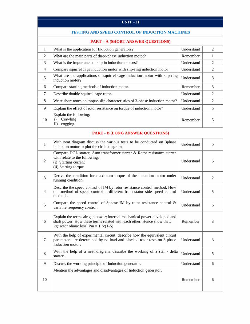
TESTING AND SPEED CONTROL OF INDUCTION MACHINES
PART – A (SHORT ANSWER QUESTIONS)
1 What is the application for Induction generators? Understand 2
2 What are the main parts of three-phase induction motor? Remember 1
3 What is the importance of slip in induction motors? Understand 2
4 Compare squirrel cage induction motor with slip-ring induction motor Understand 2
5 What are the applications of squirrel cage induction motor with slip-ring
induction motor? Understand 3
6 Compare starting methods of induction motor. Remember 3
7 Describe double squirrel cage rotor. Understand 2
8 Write short notes on torque-slip characteristics of 3-phase induction motor? Understand 2
9 Explain the effect of rotor resistance on torque of induction motor? Understand 5
10
Explain the following: i) Crawling
ii) cogging Remember 5
PART - B (LONG ANSWER QUESTIONS)
1 With neat diagram discuss the various tests to be conducted on 3phase
induction motor to plot the circle diagram. Understand 5
2
Compare DOL starter, Auto transformer starter & Rotor resistance starter with relate to the following:
(i) Starting current
(ii) Starting torque
Understand 5
3 Derive the condition for maximum torque of the induction motor under running condition.
Understand 2
4 Describe the speed control of IM by rotor resistance control method. How this method of speed control is different from stator side speed control methods.
Understand 5
5 Compare the speed control of 3phase IM by rotor resistance control &
variable frequency control. Understand 5
6 Explain the terms air gap power; internal mechanical power developed and shaft power. How these terms related with each other. Hence show that:
Pg: rotor ohmic loss: Pm = 1:S:(1-S) Remember 3
7 With the help of experimental circuit, describe how the equivalent circuit parameters are determined by no load and blocked rotor tests on 3 phase Induction motor.
Understand 3
8 With the help of a neat diagram, describe the working of a star - delta starter.
Understand 5
9 Discuss the working principle of Induction generator. Understand 6
10
Mention the advantages and disadvantages of Induction generator.
Remember 6

Part - C (ANALYTICAL Questions)
1
A cage induction motor when started by means of a star-Delta starter takes 180 % of full load current & develops 35 % of full load torque at starting. Calculate the starting current & torque in terms of full load torque when started by means of an auto transformer with 75% tapping.
Understand 3
2
A 3-phase, 400V induction motor has the following test readings: - No-
load:- 400V, 1250W, 9 A Short circuit:- 150V, 4KW,38 A Draw the circle
diagram. If the normal rating is 14.9 KW, find from the circle diagram, the
full load value of current, power factor and slip.
Understand 3
3
A 4 pole, 50 Hz, wound rotor IM has a rotor resistance of 0.56 ph and runs
at 1430 rpm at full load. Calculate the additional resistance per phase to be
inserted in the rotor circuit to lower the speed to 1200 rpm, if the torque
remains constant.
Understand 2
4
Two 50Hz, 3 phase induction motors having six and four poles respectively
are cumulatively cascaded, the 6 pole motor being connected to the main
supply. Determine the frequencies of the rotor currents and the slips
refereed to each stator field if the set has a slip of 2%.
Understand 2
5
A 3 phase, 6 pole 50Hz induction motor when fully loaded, runs with a slip
of 3%. Find the value of resistance necessary in series per phase of the
rotor to reduce the speed by 10%. Assume that the resistance of the rotor
per phase is 0.2 ohm.
Understand 3
6
Two slip ring IMs having 10 & 6 poles respectively are mechanically
coupled.
i. Calculate the possible speed when first motor is supplied from a 50
Hz supply line.
ii. Calculate the ratio of power shared by the two motors.
iii. If the smallest possible speed is to be attained independently by each
machine, calculate the frequency of the voltage to be injected in the
rotor circuit
Understand 3
7
A 6 pole, 50 Hz, 3 phase induction motor is running at 3 percent slip when
delivering full load torque. It has standstill rotor resistance of 0.2 ohm and
reactance of 0.4 ohm per phase. Calculate the speed of the motor if an
additional resistance of 0.6 ohm per phase is inserted in the rotor circuit.
The full load torque remains constant
Understand 2
8
Two 50 Hz, 3 phase Induction motors having six and four poles respectively are cumulatively cascaded, the 6 pole motor being connected to the main supply. Determine the frequency of the rotor currents and the slips referred to each stator field if the set has a slip of 2%.
Understand 3
9
A 50 KVA, 400V, 3 phase, 50 Hz squirrel cage Induction motor has full load slip of 5%. Its standstill impedance is 0.866 ohms per phase. It is started using a tapped auto transformer. If the maximum allowable supply current at the time of starting is 100A, calculate the tap position and the ratio of starting torque to full load.
Understand 3
10
A three-phase delta-connected cage type induction, motor when connected
directly to a 400 V, 50Hz supply, takes a starting current of 100 A, in each
stator phase. Calculate
i) The line current for `direct--on-line' starting.
ii) Line and phase starting currents for star-delta starting Understand 3

UNIT – III
ALTERNATORS
PART – A (SHORT ANSWER QUESTIONS)
1 State different type of synchronous generators used in hydro electrical power station.
Remember 7
2 What are the main parts of synchronous generator? Remember 7
3 Derive the EMF equation of an Alternator. Understand 7
4 What is the speed of a 4 pole 50Hz Synchronous machine? Understand 7
5 Define Synchronous speed. Understand 7
6 How can a DC generator be converted into an alternator? Understand 7
7 Discuss about armature reaction in synchronous generator. Understand 7
8 Define distribution factor. Understand 7
9 Define pitch factor. Understand 8
10 Define winding factor. Understand 8
11
Define the following
a) Short pitch winding
b) Full pitch winding
Understand 8
12
Define the following
a) Concentrated winding
b) Distributed winding
Understand 8
13
Define the following
a) Single layer winding
b) Double layer winding
Understand 8
14 Explain effect of changing the power factor on terminal voltage by keeping
the Load current, Field current and Speed constant Understand 8
15 Draw the equivalent circuit for three phase alternator. Remember 8
14 Define voltage regulation of alternator. Remember 9
15 Discuss the advantages and disadvantages of EMF method. Remember 9
16 Discuss the advantages and disadvantages of MMF method. Understand 9
17 Discuss the advantages and disadvantages of ZPF method. Understand 9
18 Explain about Xd and Xq of salient pole synchronous generator. Understand 10
19 What are the advantages of parallel operation? Understand 10
20 What are the conditions for parallel operation? Understand 10
PART – B (LONG ANSWER QUESTIONS)
1 Explain the working principle and derive EMF equation of an alternator. Understand 7
2 Discuss the procedure for determination of synchronous reactance of an alternator.
Remember 8
3 Draw the load characteristics of synchronous generator and describe the same.
Understand 8
4 Compare integral slot and fractional slot windings Remember 8
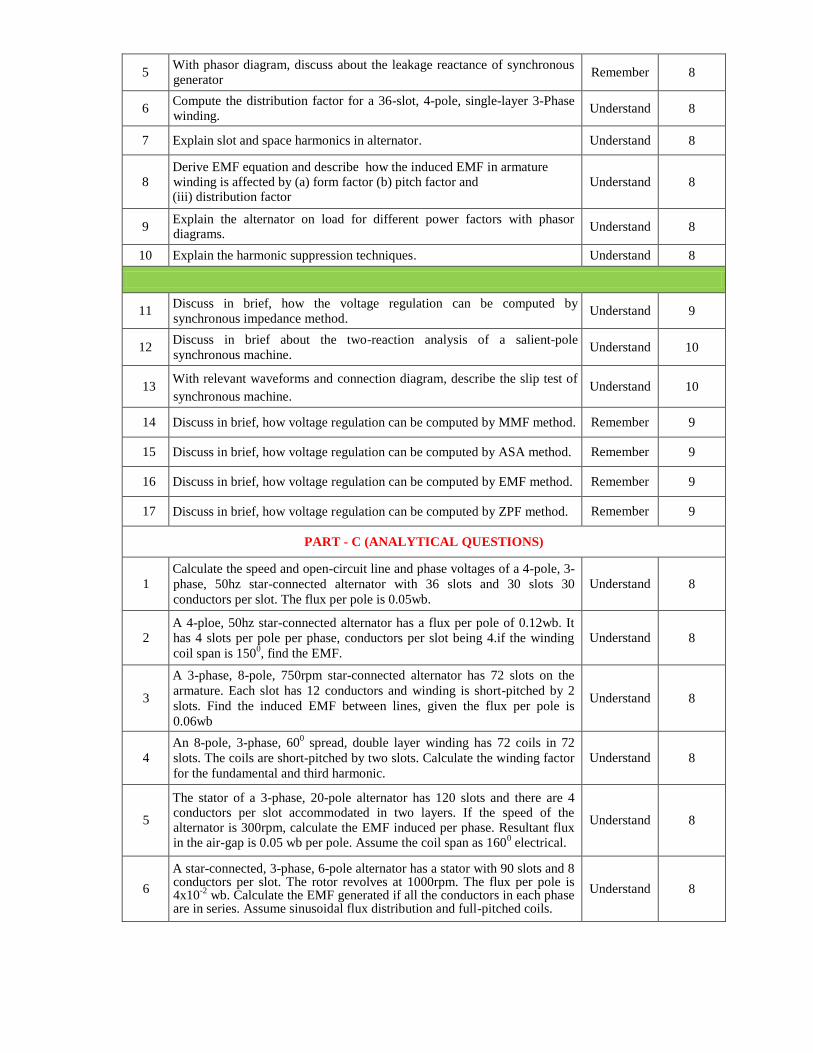
5 With phasor diagram, discuss about the leakage reactance of synchronous generator
Remember 8
6 Compute the distribution factor for a 36-slot, 4-pole, single-layer 3-Phase winding.
Understand 8
7 Explain slot and space harmonics in alternator. Understand 8
8 Derive EMF equation and describe how the induced EMF in armature winding is affected by (a) form factor (b) pitch factor and (iii) distribution factor
Understand 8
9 Explain the alternator on load for different power factors with phasor diagrams.
Understand 8
10 Explain the harmonic suppression techniques. Understand 8
11 Discuss in brief, how the voltage regulation can be computed by
synchronous impedance method. Understand 9
12 Discuss in brief about the two-reaction analysis of a salient-pole
synchronous machine. Understand 10
13 With relevant waveforms and connection diagram, describe the slip test of
synchronous machine. Understand 10
14 Discuss in brief, how voltage regulation can be computed by MMF method. Remember 9
15 Discuss in brief, how voltage regulation can be computed by ASA method. Remember 9
16 Discuss in brief, how voltage regulation can be computed by EMF method. Remember 9
17 Discuss in brief, how voltage regulation can be computed by ZPF method. Remember 9
PART - C (ANALYTICAL QUESTIONS)
1
Calculate the speed and open-circuit line and phase voltages of a 4-pole, 3-
phase, 50hz star-connected alternator with 36 slots and 30 slots 30
conductors per slot. The flux per pole is 0.05wb.
Understand 8
2 A 4-ploe, 50hz star-connected alternator has a flux per pole of 0.12wb. It
has 4 slots per pole per phase, conductors per slot being 4.if the winding
coil span is 1500, find the EMF.
Understand 8
3
A 3-phase, 8-pole, 750rpm star-connected alternator has 72 slots on the
armature. Each slot has 12 conductors and winding is short-pitched by 2
slots. Find the induced EMF between lines, given the flux per pole is
0.06wb
Understand 8
4
An 8-pole, 3-phase, 600 spread, double layer winding has 72 coils in 72
slots. The coils are short-pitched by two slots. Calculate the winding factor
for the fundamental and third harmonic.
Understand 8
5
The stator of a 3-phase, 20-pole alternator has 120 slots and there are 4 conductors per slot accommodated in two layers. If the speed of the alternator is 300rpm, calculate the EMF induced per phase. Resultant flux in the air-gap is 0.05 wb per pole. Assume the coil span as 160
0 electrical.
Understand 8
6
A star-connected, 3-phase, 6-pole alternator has a stator with 90 slots and 8 conductors per slot. The rotor revolves at 1000rpm. The flux per pole is 4x10
-2 wb. Calculate the EMF generated if all the conductors in each phase
are in series. Assume sinusoidal flux distribution and full-pitched coils.
Understand 8

7
A 16 pole, 3-phase alternator has a star-connected winding with 144 slots and 10 conductors per slot. The flux per pole is 0.03wb distributed sinusoidal and the speed is 375 rpm. Find the line voltage, if the coil span is 150
0 elec.
Understand 8
8 A 3-phase, 16-pole alternator has the following data: number of slots=192, conductors per slot=8, coil span 10 slots; speed of alternator=375rpm; flux per pole =55mwb.calculate the phase and line voltage.
Understand 8
9 For a 3-Ф winding with 4 slots per pole phase and with the coin span of 10 slot pitch, calculate the values of the distribution factor and coil span factor.
Understand 8
10 An 8-pole ac generator is running at 750rpm. What is the frequency? At what speed must the generator be run so that frequency shall be 25hz?
Understand 8
11 A 6-ploe, 50hz star-connected alternator has a flux per pole of 0.15wb. It has 6 slots per pole per phase, conductors per slot being 4.if the winding coil span is 150
0, find the EMF.
Understand 8
12
The stator of a 3-phase, 24-pole alternator has 120 slots and there are 4 conductors per slot accommodated in two layers. If the speed of the alternator is 500rpm, calculate the EMF induced per phase. Resultant flux in the air-gap is 0.06 wb per pole. Assume the coil span as 140
0 electrical.
Understand 8
13
A star-connected, 3-phase, 6-pole alternator has a stator with 90 slots and 6 conductors per slot. The rotor revolves at 1200rpm. The flux per pole is 4x10
-3 wb. Calculate the EMF generated if all the conductors in each phase
are in series. Assume sinusoidal flux distribution and full-pitched coils.
Understand 8
14
A 16 pole, 3-phase alternator has a star-connected winding with 144 slots and 8 conductors per slot. The flux per pole is 0.03wb distributed sinusoidal and the speed is 500 rpm. Find the line voltage, if the coil span is 145
0 elec.
Understand 8
15 A 3-phase, 16-pole alternator has the following data: number of slots=192, conductors per slot=6, coil span 10 slots; speed of alternator=475rpm; flux per pole =45mwb.calculate the phase and line voltage.
Understand 8
16
A 3-phase star-connected synchronous generator is rated at 1.4MVA, 11KV. The armature effective resistance and synchronous reactance are 1.2 Ω and 25Ω respectively per phase. Calculate the percentage voltage regulation for a load of 1.4375MVA at (i) 0.8pf lagging and (ii) 0.8 p.f leading. Also find out the p.f at which the regulation becomes zero.
Understand 9
17
A 3-phase, star-connected alternator is rated at 1600kva, 13500v. The armature resistance and synchronous reactance are 1.5 Ω and 30Ω respectively per phase. Calculate the percentage regulation for a load of 1280kw at 0.8leading power factor.
Understand 9
18
From the following test results, determine the regulation of a 2 KV single phase alternator, delivering a current of 100 A at 0.8 p.f. leading test results; full load current of 100 A is produced on short circuit by a field excitation of 2.5 A. An EMF of 500 V is produced on open circuit by the same field current. The armature resistance is 0.8 ohms.
Understand 9
19
A three phase star connected 1000 KVA, 11000 V alternator has rated current of 52.5 A the ac resistance of the winding per phase is 0.45 Ohms. The test results are given below; OC test : field current = 12.5 A, voltage between lines = 422 V. SC test: field current = 12.5 A , line current = 52.5 A determine the full load voltage regulation of the alternator a) 0.8 p.f. lagging b) 0.8 p.f. leading
Understand 9

20
I) A three phase star connected, 5KVA, 400 V, 50 Hz, 4-pole alternator has the following test data at rated speed
If 0.5 1 1.5 2 2.5 3 3.5 4 4.5 5 6 8
Vo
c ph 75
140
173
202
224
270
250
257
260
263
266
271
Exciting current 1 2 3
SC line current 3.6 7.2 10.8
Armature resistance per phase is 2 ohms Draw OC and SC characteristics on a graph paper and then determine unsaturated value of synchronous reactance per phase and in per unit. II) For the same synchronous machine, a) determine percentage voltage regulation at rated load at 0.8 p.f. lag and lead by synchronous impedance method under unsaturated condition. Draw relevant phasor diagrams.
Understand 9
21
A 3-phase star-connected, 1000kva, 2000v, 50hz alternator gave the following open-circuit and short circuit test readings:
Field current(Amp)
10 20 25 30 40 50
Open-circuit voltage(V)
800 1500 1760 2000 235
0 2600
Short-circuit current(Amp)
200 250 300 - - -
Draw the characteristic curves and estimate the full-load percentage regulation at i) 0.8 p.f. lagging and (ii) 0.8 p.f. leading. the armature resistance per phase may be taken as 0.2Ω.use MMF method
Understand 9
22
A 3.5 MVA, slow speed, 3-phase synchronous generator rated at 6.6kv has 62 poles. It’s direct and quadrature axis synchronous reactance as measured by the slip test is 9.6 and 6 Ω respectively. Neglect armature resistance; determine the regulation and excitation emf needed to maintain 6.6kv at the terminals when supplying a load of 2.5MW at 0.8pf lagging. What maximum power can generator supply at the rated terminal voltage, if the field becomes open-circuited?
Understand 9
23
A 10kva, 380v, 50hz, 3-phase, star-connected salient pole alternator has direct axis and quadrature axis reactance of 12Ω and 8Ω respectively. The armature has a resistance of 1Ω per phase. The generator delivers rated load at 0.8pf lagging with the terminal voltage being maintained at rated value. If the load angle is 16.15
0, determine (i) the direct axis and
quadrature axis components of armature current (ii) exciting voltage of the generator.
Understand 9
24
The following data pertains to a 15000 kva,11kv,3-phase,50hz,star-
connected turbo-alternator:
Voc line
(KV) 4.9 8.4 10.1 11.5 12.8 13.3 13.65
Field
AT in
103
10 18 24 30 40 45 50
ZPF full
load
line KV
- 0 - - - 102 -
Determine: (i) armature reaction (ii) armature reactance (iii) synchronous
reactance (iv) percentage regulation for full-load at 0.8 p.f. lagging.
Understand 9

25
A three phase star connected 1200 KVA, 12000 V alternator has rated current of 52.5 A the ac resistance of the winding per phase is 0.45 Ohms. The test results are given below; OC test : field current = 12.56 A, voltage between lines = 532 V. SC test: field current = 12.56 A , line current = 52.55 A determine the full load voltage regulation of the alternator a) 0.8 p.f. lagging b) 0.8 p.f. leading
Understand 9
26
Two identical 2MVA alternators operate in parallel. The governor of first machine is such that the frequency droops uniformly from 50hz on no-load to 47.5 Hz on full-load.the corresponding uniform speed droop of the second machine is 50hz to 48hz. How will they share a load of 3MW?
Understand 10
27
Two identical 3-phase alternators work in parallel and supply a total load of 1600kw at 11000v at a power factor of 0.92. Each machine supplies half the total power. The synchronous reactance of each is 50 ohm per phase and resistance is 2.5 ohm per phase. The field excitation of the first machine is adjusted so that armature current is 50A lagging. Determine the armature current of the second alternator, the power factor at which each is working and generated voltage of the first alternator?
Understand 10
28
A 2000KVA, 3-phase,8-pole alternator runs at 750rpm in parallel with other machines on 6000v bus-bars. Find synchronizing power on full load 0.8 pf lagging per mechanical degree of displacement and the corresponding synchronizing torque. The synchronous reactance is 6 ohms per phase.
Understand 10
29
A 3000KVA, 3-phase, 8-pole alternator runs at 850rpm in parallel with other machines on 8000v bus-bars. Find synchronizing power on full load 0.86 pf lagging per mechanical degree of displacement and the corresponding synchronizing torque. The synchronous reactance is 8 ohms per phase.
Understand 10
30
Two identical 2 MVA alternators operate in parallel. The governor of first machine is such that the frequency drops uniformly from 50 Hz on no-load to 47.5 Hz on full-load. The corresponding uniform speed drop of the second machine is 50 Hz to 48 Hz. How will they share a load of 4 MW?
Understand 10
UNIT – IV
SYNCHRONOUS MOTORS
PART – A (SHORT ANSWER QUESTIONS)
1 What are the main parts of synchronous motor? Remember 11
2 Discuss why synchronous motor has no starting torque. Understand 11
3 What are the uses of damper windings in a synchronous motor? Understand 11
4 Why synchronous motor always runs at synchronous speed? Remember 11
5 What is hunting? Remember 11
6 What are the different methods of starting synchronous motor? Remember 11
7 Why Synchronous motors are not self starting? Explain. Understand 11
8 What is a synchronous condenser? What is the use of synchronous condenser?
Understand 11
9 What are the applications of synchronous motor? Understand 11
10 Explain the suppression methods of hunting in synchronous motor Understand 11
PART – B (LONG ANSWER QUESTIONS)
1 Describe in brief the principle of operation of synchronous motor Understand 11

2 Draw and discuss the phasor diagrams of a 3-phase synchronous motor for lagging, leading and unity power factor conditions. Name all the phasor.
Understand 11
3 What do you mean by constant power circle for synchronous motor? How
it is derived? Remember 12
4 Explain different methods of starting a synchronous motor. Remember 11
5 Derive an expression of mechanical power developed for a synchronous
motor in terms of E & V. Understand 11
6 Mention the various applications of synchronous motor and describe the functions of a damper winding in a synchronous motor
Remember 11
7 Derive the expression for power developed in a synchronous motor, various conditions for maximum power developed.
Understand 11
8 Describe how a synchronous motor can be operated as a synchronous condenser.
Understand 1
9 Find an expression for power in terms of load angle, for a salient pole synchronous motor working at a lagging pf. Armature resistance may be neglected.
Understand 12
10 What are the advantages and disadvantages of the Synchronous motor? Remember 12
11 Explain the power circle diagram of the synchronous motor. Understand 12
PART - C (ANALYTICAL QUESTIONS)
1 A 2.3 kV, 3-phase, star-connected synchronous motor has Zs= (0.2+j2.2) Ω/phase. The motor is operating at 0.5 power factor leading with a line current of 200 A. Determine the generated EMF per phase
Understand 11
2
A 3-phase, 415V, 6-pole, 50hz, star-connected synchronous motor has EMF of 520V (L-L). the stator winding has a synchronous reactance of 2ohms per phase and the motor develops a torque of 220N-m.the motor is operating at 415v,50hz bus (a) calculate the current drawn from the supply and it’s power factor (b) draw the phasor diagram showing all the relevant quantities.
Understand 12
3
A 500V, 6-pole, 3-phase, 50hz, star-connected synchronous motor has a resistance and synchronous reactance of 0.3Ω and 3Ω per phase respectively. The open-circuit voltage is 600v. If the friction and core losses total 1kw,calculate the line current and power factor when the motor output is 100hp.
Understand 11
4
A 50hz, 4-pole, 3-Ф, and star-connected synchronous motor has a synchronous reactance of 12.0Ω/phase and negligible armature resistance. The excitation is such as to give an open-circuit voltage of 13.2kv.the motor is connected to 11.5KV, 50hz supply. What maximum load can the motor supply before losing synchronism? What is the corresponding motor torque, line current and power factor?
Understand 12
5
The excitation of a 415V, 3-phase, and mesh connected synchronous motor is such that the induced EMF is520V.the impedance per phase is (0.5+j4.0) Ω. If the friction and iron losses are constant at 1000watts, calculate the power output, line current, power factor and efficiency for maximum power output?
Understand 11
6
A 75 KW 3phase Y connected, 50hz, 440V cylindrical rotor synchronous motor operates at rated condition with 0.8pf leading. The motor efficiency excluding field and stator losses, is 95% and Xs=2.5Ω calculate (i) mechanical power developed (ii) armature current (iii) back EMF (iv) power angle and (v)max or pull out toque of the motor.
Understand 12

7
A 3 -phase 150kw 2300v 50Hz 1000rpm salient pole synchronous motor
has
Xd=32ohms/ph and Xq=20ohm/ph. Neglecting losses ,calculate the torque
developed by the motor if field excitation is so adjusted as to make the
back EMF twice the applied voltage and α=60°.
Understand 12
8
A 3300v, 1.5 Mw, 3 phase, Y connected synchronous motor has
Xd=4ohm/ph and Xq=3ohm/ph. Neglecting losses, calculate the excitation
EMF when motor supplies rated load at Unity power factor. Calculate the
maximum mechanical power which the motor would develop for this field
excitation.
Understand 12
9
The input to an 11000V, 3 phase star connected synchronous motor is 60A.
The effective resistance and synchronous reactance per phase are
respectively 1 ohm and 30ohms. Find (i) the power supplied to the motor
(ii) mechanical power developed and (iii) induced EMF for a power factor
of 0.8 leading
Understand 13
10
A synchronous motor having 40% reactance and a negligible resistance is
to be operated at rated load at (i) UPF (ii) 0.8 pf lag (iii) 0.8pf lead. What
are the values of induced EMF? Indicate assumptions made if any.
Understand 13
11
A 500V, 6-pole, 3-phase, 50hz, star-connected synchronous motor has a resistance and synchronous reactance of 0.29Ω and 3.5Ω per phase respectively. The open-circuit voltage is 650V. If the friction and core losses total 1kw,calculate the line current and power factor when the motor output is 110HP.
Understand 12
12
A 50hz, 6-pole, 3-Ф, and star-connected synchronous motor has a synchronous reactance of 12.2Ω/phase and negligible armature resistance. The excitation is such as to give an open-circuit voltage of 13.4kv.the motor is connected to 11.9KV, 50hz supply. What maximum load can the motor supply before losing synchronism? What is the corresponding motor torque, line current and power factor?
Understand 12
13
The excitation of a 415v, 3-phase, and mesh connected synchronous motor is such that the induced EMF is520v.the impedance per phase is (0.5+j4.0) Ω. If the friction and iron losses are constant at 1000watts, calculate the power output, line current, power factor and efficiency for maximum power output?
Understand 12
14
A 76 KW 3phase Y- connected, 50Hz, 415V cylindrical rotor synchronous motor operates at rated condition with 0.8pf leading. The motor efficiency excluding field and stator losses, is 96% and Xs=2.55Ωcalculate (i) mechanical power developed (ii) armature current (iii) back EMF (iv) power angle and (v)max or pull out toque of the motor.
Understand 12
UNIT – V
SINGLE PHASE INDUCTION MOTOR
PART - A (SHORT ANSWER QUESTIONS)
1 Compare capacitor start and capacitor run induction motor. Understand 14
2 What is shaded pole motor? Understand 14
3 What is the function of capacitor in a single phase induction motor? Understand 14
4 Why singe phase induction motor has low power factor? Remember 14
5 What is meant by split phase motor? Understand 14
6 Why starting torque in capacitor start induction motor is more than
resistance split phase induction motor? Understand 14
7 What happens when the auxiliary winding of a capacitor motor is
disconnected during running condition? Remember 14
8 What are the advantages and disadvantages of capacitor start induction
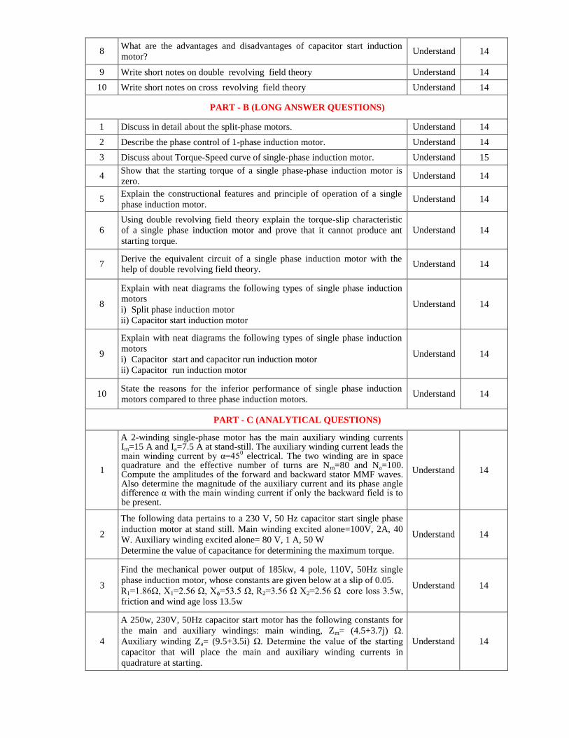
motor? Understand 14
9 Write short notes on double revolving field theory Understand 14
10 Write short notes on cross revolving field theory Understand 14
PART - B (LONG ANSWER QUESTIONS)
1 Discuss in detail about the split-phase motors. Understand 14
2 Describe the phase control of 1-phase induction motor. Understand 14
3 Discuss about Torque-Speed curve of single-phase induction motor. Understand 15
4 Show that the starting torque of a single phase-phase induction motor is
zero. Understand 14
5 Explain the constructional features and principle of operation of a single
phase induction motor. Understand 14
6 Using double revolving field theory explain the torque-slip characteristic
of a single phase induction motor and prove that it cannot produce ant
starting torque.
Understand 14
7 Derive the equivalent circuit of a single phase induction motor with the help of double revolving field theory.
Understand 14
8
Explain with neat diagrams the following types of single phase induction
motors
i) Split phase induction motor
ii) Capacitor start induction motor
Understand 14
9
Explain with neat diagrams the following types of single phase induction
motors
i) Capacitor start and capacitor run induction motor
ii) Capacitor run induction motor
Understand 14
10 State the reasons for the inferior performance of single phase induction
motors compared to three phase induction motors. Understand 14
PART - C (ANALYTICAL QUESTIONS)
1
A 2-winding single-phase motor has the main auxiliary winding currents Im=15 A and Ia=7.5 A at stand-still. The auxiliary winding current leads the main winding current by α=45
0 electrical. The two winding are in space
quadrature and the effective number of turns are Nm=80 and Na=100. Compute the amplitudes of the forward and backward stator MMF waves. Also determine the magnitude of the auxiliary current and its phase angle difference α with the main winding current if only the backward field is to be present.
Understand 14
2
The following data pertains to a 230 V, 50 Hz capacitor start single phase
induction motor at stand still. Main winding excited alone=100V, 2A, 40
W. Auxiliary winding excited alone= 80 V, 1 A, 50 W
Determine the value of capacitance for determining the maximum torque.
Understand 14
3
Find the mechanical power output of 185kw, 4 pole, 110V, 50Hz single
phase induction motor, whose constants are given below at a slip of 0.05.
R1=1.86Ω, X1=2.56 Ω, Xϕ=53.5 Ω, R2=3.56 Ω X2=2.56 Ω core loss 3.5w,
friction and wind age loss 13.5w
Understand 14
4
A 250w, 230V, 50Hz capacitor start motor has the following constants for
the main and auxiliary windings: main winding, Zm= (4.5+3.7j) Ω.
Auxiliary winding Za= (9.5+3.5i) Ω. Determine the value of the starting
capacitor that will place the main and auxiliary winding currents in
quadrature at starting.
Understand 14

Prepared By:
Mr. K Devender Reddy, Assistant Professor
Mr. P Mabuhussain, Assistant Professor
HOD, EEE
5
A single phase induction motor has stator windings in space quadrature
and is supplied with a single phase voltage of 200V at 50Hz. The standstill
impedance of the main winding is (5.2+10.1i) and the auxiliary winding is
(19.7+14.2j). Find the value of capacitance to be inserted in the auxiliary
winding for maximum starting torque.
Understand 14
6 What is the motor torque Tm required to accelerate an initial load of 3*10
-4
kg m2 from f1 = 1500 Hz to f2 = 2500 Hz during 100 ms. The frictional
torque Tf is 0.05 N-m and the step angle is 1.7˚.
Understand 14
7
A 230 V, 4-pole, 50Hz single phase induction motor has the following data
at standstill. Main winding (1.5+j4.0)Ω, starting winding (2.2+j5.5)Ω. For
making the motor develop maximum starting torque, find the value of (i)
resistor (ii) capacitor in series with the starting winding.
Understand 14
8
A 230 V, 380 W, 50 Hz, 4 pole, single phase induction motor gave the
following test results:
No load test: 230 V, 84 W, 2.8 A
Blocked rotor test: 110 V, 460 W, 6.2 A
The stator winding resistance is 4.6 Ω and during the blocked rotor test, the
auxiliary winding is open. Determine the equivalent circuit parameters.
Understand 14
9
A 230 V, 50 Hz, 4 pole, class A, single phase induction motor has the
following parameters at an operating temperature of 630C:
R1m= 2.51Ω, R2m = 7.81Ω, Xm= 150.88Ω, X1m= 4.62Ω, X’2= 4.62Ω
Determine the main winding current and power factor when the motor is
running at a slip of 0.05 at the specified temperature of 630 C.
Understand 14
10
A 125 W, 4 pole, 110 V, 50 Hz single phase induction motor delivers
rated output at a slip of 6%. The total copper loss at full load is 25 Watts.
Calculate the full load efficiency and the rotor copper loss caused by the
backward field. Rotational losses may be assumed to be 25 Watts. Neglect
stator copper loss.
Understand 14