Embed Size (px)
Citation preview

b£
lk-
NASA Technical Memorandum 101724
F-18 High Alpha Research Vehicle Surfacej-
' Pressures: Initial In-Flight Results andCorrelation With Flow Visualization and
Wind-Tunnel Data
David F. Fisher, Daniel W. Banks, and David M. Richwine
(NASA-TM-I01774) F-IB HIGH ALPHA RESEARCH
VEHICLE SURFAC_ PRESSURFS: INITIAL IN-FLIGHT
RESULTS AND CNRRELATION WITH FLOWVISUALIZATIqN ANO WIND-TUNNEL DATA (NASA)
CSCL OIA GJIO_36 p
Nql-lg051
Unclas
0001o35
August 1990
I IASANational Aeronautics and
Space Administration
https://ntrs.nasa.gov/search.jsp?R=19910009738 2018-08-09T16:27:55+00:00Z

.,,,i
i_ _1_
tl
z_
; i
Ii
!i
7
i - i
tl

National Aeronautics andSpace Administration
Ames Research Center
Dryden Flight Research FacilityP.O. Box 273Edwards, California 93523-0273
NASA
ReprytoA.. of: D-ATD/90-144 November 21, 1990
TO:
FROM:
SUBJECT:
Report Recipient
ATD/Acting Chief, Dryden Reports & Presentations Branch
Report Errata
Figure 10(a) (fuselage station 142) of NASA Technical Memorandum 101724 has been
corrected. Please substitute page 6 in the text portion (second column, last two
paragraphs contain revised material) and page 23 in the figures section of the reportwith the enclosed corrections.
r
Marilee S. Morgan
Enclosures
\\
\
: \
\


ERRATA
NASA Technical Memorandum 101724
F-18 High Alpha Research Vehicle Surface Pressures: Initial In-Flight Resultsand Correlation With Flow Visualization and Wind-Tunnel Data
David F. Fisher, Daniel W, Banks, and David M. Richwine
August 1990
Figure 10(a) (fuselage station 142) of NASA Technical Memorandum101724 has been corrected. Please substitute page 6 in the text
portion (second column, last two paragraphs contain revised
material) and substitute page 23 in the figures section of the reportwith the enclosed corrections.


NASA Technical Memorandum 101724
t
F-18 High Alpha Research Vehicle SurfacePressures: Initial In-Flight Results andCorrelation With Flow Visualization andWind-Tunnel Data
David F. FisherNASA Ames Research Center, Dryden Flight Research Facility, Edwards, California
Daniel W. BanksNASA Langley Research Center, Hampton, Virginia
David M. RichwinePRC Systems Services, Edwards, California
1990
National Aeronautics andSpace AdministrationAmes Research Center
Dryden Flight Research FacilityEdwards, California 93523-0273

P _
: IZ--- - Z

F-18 HIGH ALPHA RESEARCH VEHICLE SURFACE PRESSURES:
INITIAL IN-FLIGHT RESULTS AND CORRELATION WITH
FLOW VISUALIZATION AND WIND-TUNNEL DATA
David E Fisher*
• NASA Ames Research Center
Dryden Flight Research Facility
Edwards, CA
Daniel W. Banks*
NASA Langley Research Center
Hampton, VA
David M. Richwine*
PRC Systems Services
Edwards, CA
Abstract
Pressure distributions have been reported at anglesof attack from 10_ to 50° and at Mach 0.23 to 0.60
at five fuselage stations on the forebody and at three
fuselage stations on the leading-edge extensions of the
NASA F-18 high alpha research vehicle (HARV). The
reported results have been correlated with flow visu-
alization results obtained during a previous investiga-tion on the HARV and with test results obtained from
a 6-percent-scale F-18 wind-tunnel model. A general
trend in the data from the forebody was for the maxi-
mum suction pressure peaks to first appear at angle of
attack (a) _., 19° and increase in magnitude as angle of
attack was increased. The general trend of the leading-
edge extension (LEX) pressure distribution was the in-
ward progression of the maximum suction peaks, the
increase in magnitude of the maximum suction pres-
sure peaks up to vortex core breakdown, and then the
decrease and general flattening of the pressure distribu-
tion beyond the LEX primary vortex core breakdown.
No significant effect of Mach number was noted for the
forebody results for the Mach number range reported.
However, at all three LEX orifice stations a substantial
compressibility effect resulted in a significant reduc-
tion in vortex-induced suction pressure as Mach num-
ber increased. The forebody primary and the LEX sec-
ondary vortex separation lines, as identified by the sur-
face flow visualization, correlated well with the end
"AerospaceEngineer.MemberAIAA.Copyright ©1990 by the AmericanInstitute of Aeronauticsand
Astronautics, Inc. No copyright is assertedin the United Statesunder Title 17,U.S.Code. The U.S.Government has aroyalty-freelicense to exercise all rights under the copyright claimed hereinfor Governmental purposes. All other rights are reserved by thecopyright owner.
of pressure recovery, leeward and windward respec-
tively, of the maximum suction pressure peaks. The
flight to wind-tunnel correlations were generally good,
with some exceptions.
Nomenclature
¢7p pressure coefficient
C_ pressure coefficient correspondingto local speed of sound,
CFD computational fluid dynamics
CRT cathode ray tube
d diameter of fuselage forebody, in.
d,,n,_z diameter of fuselage forebody along
major axis, in.
drain diameter of fuselage forebody along
minor axis, in.
electronic counter measures
fuselage station, in. (nose apex at59.82 in.)
high alpha research vehicle
High Alpha Technology Program
leading-edge extension
laminar separation bubble
length of aircraft from nose apex to
engine exhaust plane, 54.4 ft
free-stream Mach number
mean aerodynamic chord, 11.525 ft
pulse code modulation
ECM
ES.
HARV
HATP
LEX
LSB
g
M_
m.a.c.
PCM

PROM
R
Re_
$2
8
y
A
g
0
programmed read only memory
reattachrnent line location
Reynolds number based on mean
aerodynamic chord
Reynolds number based on diameter
Reynolds number based on local
maximum fuselage diameter, corrected
for angle of attack using the method ofRef. 17
primary separation line location
secondary separation line location
tertiary separation line location
local span distance from LEX fuselage
junction to LEX leading edge, in.
distance from nose apex along longitudinalaxis of aircraft, ft
distance along LEX local semispan, in.
aircraft angle of attack, deg, fight wingtipangle-of-attack vane corrected for
upwash and boom bending
angle of attack used in the determination
of Re,t, (at ES. 70, 85, and 107,
a' = t_ - 5.6 ° because the nosecone
is depressed from the horizon 5.6°;
at ES. 142 and 184, d = a)
aircraft angle of sideslip, deg, average of
left- and right-wingtip sideslip vanes
corrected for angle of attack
differential
ratio for specific heats of air, 1.4
forebody cross-section circumferential
angle, deg, (0 ° is bottom centedine,positive is clockwise as seen from a
front view, 0" to 360 °)
Introduction
In recent years, more emphasis has been placed on
expanding the envelope of fighter aircraft to include
controlled flight at high angle of attack. Fighters such
as the F-18 and F-16 aircraft utilize leading-edge ex-
tensions (LEXs) or wing body strakes which provideadditional lift because of the vortical flow these de-
vices develop at moderate-to-high angles of attack.l
However, the prediction and control of this vortical
flow and the mutual interactions of the vortices are not
well understood. The combined effect of the LEX or
2
wing body strake vortices, as well as the forebody vor-
tices on the vehicle aerodynamics, must be considered
to avoid any adverse stability and control and other
problems such as buffet.
Understanding the vortical flow interactions on
scale models in wind tunnels can be difficult. Experi-mental tests in wind tunnels with different scale mod-
els have provided conflicting results, even with tests
conducted at the same Reynolds number. 2 In such sub-
scale model tests, the interaction of the forebody and
LEX vortices on 6- and 7-percent scale F-18 mod-
els typically resulted in apparent lateral stability for
all angles of attack, including stall and poststall re-
gions. However, airplane flight data and wind-tunnel
test results for the large-scale (16 percent) model, at
low Reynolds numbers, indicated a region of lateral in-
stability near maximum iift. This apparent scale effect
still has not been resolved. Understanding such scale
effects is essential for the successful design of future
fighters intended to operate at high angles of attack.
Currently NASA is conducting a High Alpha Tech-
nology Program (HATP) to increase the understand-
ing, improve prediction techniques, provide design
guidelines, and investigate new concepts for vortex
control on advanced, highly maneuverable aircraft at
high angles of attack. This program utilizes the F-18
configuration as a validation and demonstration ap-
proach. It consists of wind-tunnel tests of subscale 3-4
and full-scale models and components; calibration for
computational fluid dynamics (CFD) codes, 5-9 pi-
loted simulations, and full-scale flight testing. ]°-16
(Also: Fisher, D.E, Curry, R.E., Del Frate, J.H., and
Richwine, D.M., paper to be published in the serial
Flow Visualization V, and Fisher, David F., Del Frate,
John H., and Richwine, David M., NASA Technical
Memorandum, to be published.)
As part of this program, extensive pressure distri-bution and fl0wvisualizafion shidies lmve been con-
ducted on _e NASA F-18 high alpha research ve-
hicle (HARV) at the Ames Research Center, Dryden
Flight Research Facility. Surface and off-surface flow
visualization results (obtained in-flight on the NASA
F-18 HARV, highlighting the extensive vortical three-dimensional separated flow on the aircraft at angles of
attack up to 55 °) have been reported in Refs. 10-15.
In this paper, results from pressure measurements on
the forebody and the leading-edge extensions (LEX)
are reported from both stabilized and dynamic flight
conditions, at Mach 0.23 to 0.60, and at Reynolds num-
|

hers up to 25 × 106 based on wing mean aerody-
namic chord (m.a.c.). Also presented arc correlations
with previously obtained results from flow visualiza-
tion and from wind-tunnel pressure measurements onsubscale models.
Vehicle Description
The NASA HARV (Fig. 1) is a single-place prepro-
duction F-18 aircraft built by the McDonnell Douglas
(St. Louis, Missouri) and Northrop (Newbury Park,
California) corporations. It is powered by two GE
(General Electric, Lynn, Massachusetts) F404-GE-400
afierbuming turbofan engines. The aircraft features a
midwing with leading- and trailing-edge flaps which
operate on a schedule that is a function of angle of at-tack and Mach number. For free-stream Mach num-
ber (Moo) < 0.76 and angle of attack (o0 > 26 °,
the leading-edge flap is down 34 ° (maximum), and the
trailing-edge flap is at tY'. Leading-edge extensions are
mounted on each side of the fuselage from the wing
roots to just forward of the windscreen. The aircrafthas twin vertical stabilizers canted out 20° from the
vertical and differential all-moving horizontal tails.
The NASA F-18 HARV, with the current flight con-
trol computers and control laws (8.3.3 programmed
read only memory (PROM) se0, is flown by NASA pi-
lots in the fighter escort configuration without stores.
The aircraft carries no missiles and the wingtip
Sidewinder missile launch racks have been replaced
with special camera pods and wingtip airdata booms.
The flight test noseboom has been removed from the
aircraft and a NASA flush airdata system 16 has been
installed. The aircraft has an unrestricted angle-of-
attack flight envelope in this configuration, with the
center of gravity between 17 percent and 25 percent
m.a.c., as defined by the Naval Air Training and Oper-
ating Procedures Standardization (NATOPS) manual.
Experiment Description
Pressure measurements were made on both the
forebody and the LEXs of the F-18 HARV at se-
lected fuselage locations. These fuselage locations
correspond with orifice locations on both the 6- and
16-percent scale models.
Five rings of static pressure orifices were in-
stalled on the fuselage forward of the canopy as
shown in Fig. 2. At the first 2 rows, fuselage sta-
tion (F.S.) 70 (ratio of length from apex to fuselage
length (x,/g) = 0.015) and ES. 85 (x/g. = 0.038), 30
static pressure orifices were equally spaced about the
nosecone. Two extra orifices were located at the fore-
body cross-section circumferential angle (0) = 90 °
and 270 ° (0° is bottom centerline, positive is clock-
wise as seen from a front view, 0 ° to 360°). At
the last 3 rows, ES. 107 (x/g = 0.071), F.S. 142
(x/e = 0.126), and ES. 184 (x/g = 0.190) 64 orifices
were spaced about the fuselage at each location with
orifices more closely spaced (every 3°) on the upper
surface where larger pressure gradients were expected.
At ES. 184, two large vents for the gun hay were lo-
cated on the lower portion of the fuselage and no ori-rices were installed there.
Both the left and right LEXs were instrumented
with three rows of pressure orifices located at F.S. 253
(x/e = 0.295), ES. 296 (x/e = 0.361), and F.S. 357
(x/e = 0.454). Approximately 13 to 20 orifices were
installed at each station on the upper surface of eachLEX and 4 to 5 at each station on the lower surface,
respectively. The orifices were located with the clos-
est spacing near the leading edge. A total of 384 sur-
face static pressure measurements were made on the
fuselage and LEXs.
A cross section of the orifice stations and the ori-
entation of the orifices is given in Fig. 3. The view
is looking aft on the aircraft with the bottom fuselage
centerline at 0 ° and the top centerline fuselage at 180 °.
The first three fuselage stations were circular in crosssection and were canted forward 5.6 ° to coincide with
the depression of the nosecone centerline. At ES. 142
and ES. 184, the fuselage cross section became some-
what elliptical with the major axis in the vertical plane.
The ratio of the major to minor axis was 1.10 and 1.35
for F.S. 142 and E S. 184, respectively. At the LEX sta-
tions, y/8 = 0.0 is defined as the LEX fuselage junction
while _/8 = 1.0 is the leading edge of the LEX, + 1.0
for the left-LEX leading edge and - 1.0 for the right-
LEX leading edge.
Several protrusions and discontinuities on the fuse-
lage should be noted. The nosecone was generally
smooth and free of discontinuities, with the nosecone-
fuselage junction at F.S. 128.5. Two small elliptical-
shaped electronic counter measures (ECM) antenna
covers, Fig. 4(a), were located on the sides of the fuse-
lage centered at F.S. 134, 0 = 85° and 275 ° and were
approximately 9.5 in. long, 4 in. wide and protruded
approximately 1.7 in. Located on the upper surface,
between F.S. 128.5 and ES. 188 and between 0 ,,_
138 ° and 165 °, were doors covering the in-flight refu-
eling probe. While these doors were nominally flush,
there were gaps and small protrusions present. Two

small production angle-of-attack vanes were installedat ES. 165, one at 0 ,.o 700 and the other at 0 ,-, 290 °.
Two aircraft production pitot-static probes, Fig. 4(a),
were located on the lower fuselage at ES. 164 to
ES. 177 and 0 = 35° and 325 °. On this preproduction
aircraft, the gun port exits normally located on the up-
per centerline near E S. 122, were replaced by a fairing
without ports. Of the protrusions noted, the ECM an-
tenna covers and the production pitot-static probes had
the greatest effect on the pressure distributions, as will
be shown later. The LEX, Fig. 4(b), was virtually free
of significant protrusions forward of the orifice rows.
Instrumentation
Each orifice on the forebody was connected to
temperature-controlled electronic scanning pressure
modules with 6 ft of 0.062-in. id pneumatic tubing.
On the LEXs, the tubing for each orifice was matched
in length at each orifice row but varied from 2 1/2 to
3 1/2 ft at the three stations. It was previously deter-
mined that 8 ft of 0.062-in. flexible tubing would have
a pneumatic lag of approximately 10 msec at an alti-
tude of 20,000 fi.t6 Reference pressure for the mod-
ules was supplied through l/4-in, tubing to a refer-
ence pressure tank with an internal volume of 50 in 3
located in the forebody, vented to the radome com-
partment, and monitored by a high-resolution absolute
pressure transducer. The pressure transducer within
each module was scanned sequentially 25 times/sec
by a 10-bit pulse code modulation (PCM) data sys-
tem. In-flight zero differential pressure readings were
taken before each test point and were used during post-flight data reduction to correct the data for calibra-
tion offsets. On the forebody, 4-216 lb/ft 2 differen-
tial range transducers were used while 4-720 lb/ft 2
differential range transducers were used on the LEXs.
Accuracy for the forebody pressure measurements
is estimated to be 1 lb/ft 2 and 3.5 lb/ft 2 for the
LEX measurements.: z: 2: : :
Airspeed, altitude, angle of attack, and angle of
sideslip greater than 4-20 °. Free-stream Mach num-
ber, altitude, and dynamic pressure were determined
using calibrated data from the swiveling probe on the
left wingboom. Aircraft angle of attack was mea-
sured by using a vane on the right wingboom and
corrected for upwash and boom bending. Angle of
sideslip was determined as the average of the left- and
right-wingboom sideslip vane measurement corrected
for angle of attack. From unpublished data, it is esti-
mated that angie of attack and angle of sideslip were
accurate to 4-0.5 ° for angles of attack up to 400, and
4-1 ° for angles of attack up to 50 °. It is also estimated
that Moo is accurate to +0.005 at ot = 50 °, and 4-0.003
for angles of attack below 30 ° .
The data from the above measurements, as well as
the standard aircraft control positions, inertial system,
and accelerometer parameters were transmitted to a
ground station. These critical parameters were moni-
tored by engineers and technicians in real time on strip
charts, cathode ray tube (CRT) displays, and pressure
distribution plots.
Flight Test Conditions
Data were obtained in both quasi-stabilized l- 9
flight maneuvers, as well as windup turns and spi-
ral dives. Data were obtained at nominal altitudes of
20,000 and 45,000 ft. At the higher angles of attack,
constant altitude could not be maintained during the
l-g maneuvers and data were obtained in a descent.
During the windup turns and spiral dives the maneu-vers were much more transient. In the first case the
Mach number decreased rapidly. In the second case the
altitude decreased rapidly. As mentioned previously in
the Instrumentation section, the frequency response of
the pressure system was less than 10 msec and little
lag was introduced. Time segments of 0.4-sec dura-
tion were used for data analysis purposes, with approx-
imately 10 time-points averaged.
Results and Discussion
sideslip were measured using airspeed booms mounted Forebody Resultson specially designed wingtip photo pods as shown : :
in Fig. 5. On the right wingtip, Fig. 5(a), a standard
NACA noseboom 18 was installed with the tip mounted
7.3 ft forward of the wingtip leading edge. On the left
wingtip a swiveling probe, Fig. 5(b), was similarly lo-
cated. The swiveling probe was designed with four
vanes to align the probe head with the local airstream.
The probe could align with the airstream for aircraft
angles of attack from -100 to +500 and angles of
The forebody pressure distribution results are pre-sented as pressure coefficients as a function of circum-
ferential angle, (0) for each of the five forebody sta-
tions. The effect of angle of attack and Mach num-ber, as well as the correlation with flow visualiza-
tion and wind-tunnel test results, are presented in the
following sections.
4
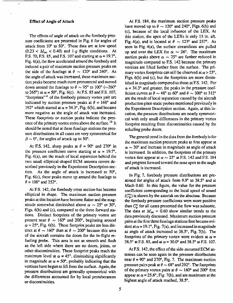
Effectof Angleof Attack
The effects of angle of attack on the forebody pres-
sure coefficients are presented in Fig. 6 for angles of
attack from 10° to 50 °. These data are at low speed
(0.23 < Moo < 0.40) and 1-g flight conditions. At
F.S. 70, F.S. 85, and ES. 107 and starting at c_= 19.7 °,
Fig. 6(a), the flow accelerated around the forebody and
induced a pair of maximum suction pressure peaks on
the side of the fuselage at 0 ,,_ 120 ° and 240 °. As
the angle of attack was increased, these maximum suc-
tion peaks became much more pronounced and moved
down around the fuselage to O _ 95 ° to 100O (,-,260 °
to 265 °) at ot = 50 °, Fig. 6(c). At F.S. 85 and F.S. 107,
"footprints" 4 of the forebody primary vortex pair are
indicated by suction pressure peaks at 0 = 168 ° and
192 ° which started at c_= 34.3 °, Fig. 6(b), and becarne
more negative as the angle of attack was increased.
These footprints or suction peaks indicate the pres-
ence of the primary vortex cores above the surface. 19 It
should be noted that at these fuselage stations the pres-
sure distributions in all cases are very symmetrical for
,,_ 0°, for angles of attack up to 50 °.
At F.S. 142, sharp peaks at 8 = 90 ° and 270 ° in
the pressure coefficient curve starting at ot = 19.7 °,
Fig. 6(a), are the result of local separation behind the
two small elliptical-shaped ECM antenna covers de-
scribed previously in the Experiment Description sec-
tion. As the angle of attack is increased to 50%
Fig. 6(c), these peaks move up around the fuselage to8 = 108 ° and 252 °.
At F.S. 142, the forebody cross section has become
elliptical in shape. The maximum suction pressure
peaks at this location have become flatter and the mag-
nitude somewhat diminished above a ,-., 25 ° or 30 °,
Figs. 6(b) and (c), compared to the three forward sta-
tions. Distinct footprints of the primary vortex are
present near 0 --, 160 ° and 200 °, beginning around
ot = 25 °, Fig. 6(b). These footprint peaks are less dis-tinct at 0 ,,_ 160 ° than at 0 ,_ 200 ° because this area
of the aircraft contains the doors for the in-flight re-
fueling probe. This area is not as smooth and flush
as the left side where there are no doors, joints, or
other discontinuities. These footprint peaks reach the
maximum level at ot = 45 °, diminishing significantly
in magnitude at a = 50 °, probably indicating that the
vortices have begun to lift from the surface. Again, the
pressure distributions are generally symmetrical with
the differences accounted for by local protuberancesor discontinuities.
At F.S. 184, the maximum suction pressure peaks
have moved up to 0 ,,., 120 ° and 240 °, Figs. 6(b) and
(c), because of the local influence of the LEX. At
this station, the apex of the LEXs is only 13 in. aft,
Fig. 4(a), and is located at 0 ,-_ 123 ° and 237 °. As
seen in Fig. 4(a), the surface streamlines are pulled
up and over the LEX for a ,_, 26 °. The maximum
suction peaks above oe ,,_ 25 ° are further reduced in
magnitude compared to ES. 142 because the primary
vortices are lifted further from the surface. The pri-
mary vortex footprints can still be observed at o_> 25 °,
Figs. 6(b) and (c), but the footprints are more dimin-
ished in magnitude compared to those at F.S. 142. For
= 34.3 ° and greater, the peaks in the pressure coef-ficient curves at 0 ,,_ 48 ° to 60 ° and 0 ,-_ 300 ° to 312 °
are the result of local separation caused by the aircraft
production pitot-static probes mentioned previously in
the Experiment Description section. Again, at this lo-
cation, the pressure distributions are nearly symmetri-
cal with only small differences in the primary vortex
footprint resulting from discontinuities caused by the
refueling probe doors.
The general trend in the data from the forebody is for
the maximum suction pressure peaks to first appear at
a ,-_ 20 ° and increase in magnitude as angle of attack
is increased. In addition, the footprints of the primary
vortex first appear at a ,,_ 25 ° at F.S. 142 and F.S. 184
and progress forward toward the nose apex as the angleof attack is increased.
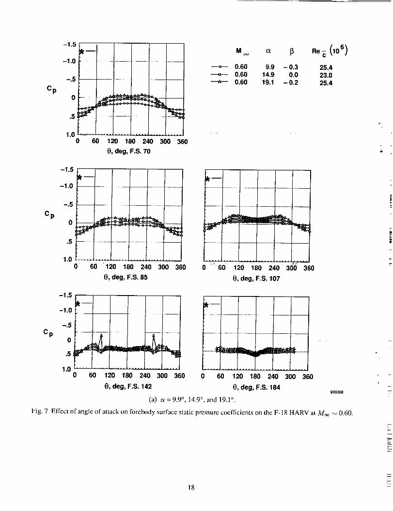
In Fig. 7, forebody pressure distributions are pre-
sented for angles of attack from 9.9 ° to 38.5 ° and at
Mach 0.60. In this figure, the value for the pressure
coefficient corresponding to the local speed of sound
(C_) is shown by the asterisk on the abscissa. Becausethe forebody pressure coefficients were more positive
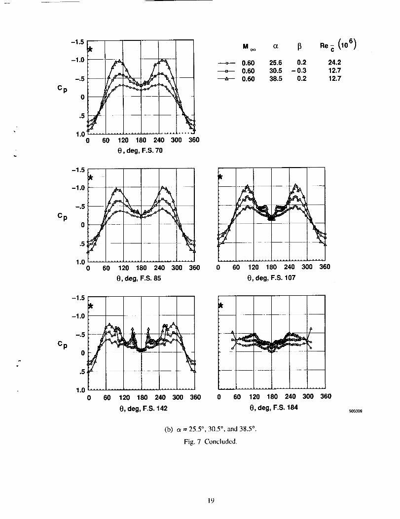
than U_ for all cases presented the flow was subsonic.The data at Moo = 0.60 show similar trends to the
data previously discussed. Maximum suction pressure
pairs at the first three fuselage stations first became evi-
dent at cx= 19.1 °, Fig. 7(a), and increased in magnitude
as angle of attack increased to 38.5 °, Fig. 7(b). The
footprints of the primary vortex were evident at ¢_ =38.5 ° at F.S. 85, and at a = 30.0 ° and 38.5 ° at ES. 107.
At KS. 142, the effect of the side-mounted ECM an-
tennas can be seen again in the pressure distributions
near 0 - 90 ° and 270 °, Fig. 7. The maximum suction
pressure pairs peak at 0 _-, 68 ° and 292 °. The footprints
of the primary vortex pairs at 0 ,-, 160 ° and 200 ° first
appear at ot = 25.6 °, Fig. 7(b), and are maximum at the
highest angle of attack reached, 38.5 ° .

The magnitude of the pressure distributions at
F.S. 184, Fig. 7, are generally flatter and at or below
the magnitude of those at F.S. 142. The effect of the
production pitot-static probes can be seen again at t_ =
38.5 ° and at 0 = 48 ° and 312 °, Fig. 7(b).
Effect of Mach Number
Figure 8 shows the data for all five orifice stations
on the fuselage for Mach 0.26 to 0.60 for cv ,-, 31°.
Only a very smaU effect of Mach number is noted at
the fuselage locations for the Mach number range re-
ported. At the first four stations, the Moo = 0.60 data
are slightly more negative than the data at Moo -- 0.26.
At F.S. 184 the data at Moo = 0.26 are slightly more
negative.
Also given in Fig. 8 are the effective Reynolds num-
bers based on local maximum fuselage diameter cor-
rected for angle of attack (Red,) 17. Reynolds num-
bers based on diameter (Red) are commonly used to
describe the flow about cylinders. Reynolds numbers
based on diameter (Red) < 2 x 10⁵ are generally con-sidered subcritical where the flow is laminar and lam-
inar separation occurs. At Red between 2 x 10⁵ and
4 x 10⁵, the flow is critical and laminar separation is
followed by turbulent reattachment enclosing a bub-
ble. Reynolds numbers based on diamter (Red) greater
than 4 x 10⁵ are supercritical or hypercritical where
transition moves forward, eventually to the vicinity of
the forward stagnation point. In Fig. 8, all data are in
the supercritical Reynolds number range or higher for
cylinders. At this Reynolds number range, a limited
amount of data for cylinders in cross flow in Ref. 17
would predict a significant Mach number effect which
was definitely not observed in the flight data shown in
Fig. 8.
Correlation of Forebody Pressure Distributionswith Flow Visualization Data
Surface flow visualization using the emitted fluid
technique was previously obtained on the F-18
HARV. 12-14 Selected results are presented in Fig. 9
for angles of attack of 30 ° and 47 ° . Noted in the fig-
ures are the primary vortex separation lines (ocl), see-
ondary vortex separation lines (5'2), reattachment lines
(R), and laminar separation bubbles (LSBs), as deter-
mined by surface flow visualization. Also shown in
Fig. 9(a) is a schematic of the flow about the forebody.
In Fig. 10 these results are correlated with forebody
flight pressure distributions at a = 30.0 ° and 48.1 °.
The surface flow visualization and the forebody pres-
sure measurements were obtained on separate flights.
Some variation in the results can therefore be expected
because of slightly different test conditions and test
techniques.
At F.S. 70, (Fig. 10(a)) for a ,,_ 30 ° and at ES. 70,
ES. 85, and F.S. 107 (Fig. 10(b)) for ot ,,_ 47 °, LSBswere identified in the surface flow visualization. TM
Laminar separation bubbles are more closely identi-
fied with the critical Reynolds number range (2 x 10⁵
< _Rea < 4 x 10⁵) than the supercriticaI range (4 x 10⁵
<Rea<6 x 10⁶). 17 AtES. 107,Fig. 10(b),theLSBs
located by the surface flow visualization at 0 = 113 °
and 247 ° , correlate well with the kinks in the pressuredistribution at 0 = 108 ° to 114 ° and 0 = 246* to 252 °.
This is consistent with the discussion in Ref. 20 where
the kink or flattening in the pressure distribution was
correlated with an LSB for a tangent-ogive cylinder.
Laminar separation bubble kinks in the pressure dis-tribution are also noted for the data at ot = 30 ° at
ES. 107, Fig. 10(a), though laminar separation bub-
bles were only noted in the surface flow visualization
near ES. 70. Unfortunately, the orifices at ES. 70 and
ES. 85 were not dense enough to define the kinks in
the pressure distributions as a result of the LSBs. Thekinks on the windward side of the maximum suction
pressure peaks at ES. 107 for 0 = 84 ° to 90 ° and 0 =
270 ° to 276 ° are not explained at this time. No devia-tions in the surface streamlines were detected in the
flow visualization at these cjreumferential locations.
The discontinuities of the nosecone±fuseiage junction
precluded any laminar flow on the forebody beyond
ES. 128.5. The peaks in the pressure distributions for
ES. 142 at 0 --, 95 ° and 265 ° (Fig. 10(a)) are caused
by the ECM antenna covers as noted earlier.
The primary separation lines (Sl) as identified by
the surface flow visualization in Fig. 9, occurred at the
end of pressure recovery on the leeward side of the
forebody. This can be seen in Fig. 10(a) at ES. 142
and ES. 184 and in Fig. 10(b) at ES. 85 to ES. 184.
This also agrees weU with the data of Refs. 19 and 20
for a cone and an ogive. The secondary vortex separa-
tion line (5'2) occurs slightly outboard of the footprints
of the primary vortex pairs. This occurs at F.S. 142
and ES. 184 as shown in Fig. 10(a) and at ES. 107 to
ES. 184 as shown in Fig. 10(b).

ComparisonwithWind-Tunne/TestResults.
Forebody pressure distribution test results from a 6-
percent-scale F-I 8 wind-tunnel model 4 are correlated
with flight data at t_ ,,_30* at Moo --, 0.30 and 0.60 and
at o_= 50 °, Moo "," 0.20 in Fig. 11. Wind-tunnel data
were available at only three forebody fuselage stations,
F.S. 107, 142, and 184.
In Fig. ll(a), flight and wind-tunnel data are pre-
sented for o_ = 30.0 ° and Moo "_ 0.30. At these con-
diti0ns the comparisons are good, with the exception
being at ES. 142 where the wind-tunnel data do not
indicate the footprints of the primary vortex pair at
0 ,_ 160 ° and 200 °. At ES. 107, there appears to be
a kink in the wind-tunnel pressure distribution caused
by an LSB at 0 ,-_ 120 ° to 132 °, which is slightly more
leeward than the flight values. The model and flight
Reynolds numbers (Re,t) for all three stations are all
in the supercritical range even though the flight values
are almost an order of magnitude greater. The ECMantenna-covers were not simulated on the model and
hence the peaks near 0 = 90 ° and 270 ° do not appearin the wind-tunnel data at ES. 142.
At ot _ 30° and Moo = 0.60, Fig. 11(b), there were
only fair comparisons between flight and wind-tunnel
test results. At these conditions, the wind-tunnel
maximum suction pressure peaks were approximately
zXG'_,= 0.1 below the flight values. The kinks in the
pressure distributions caused by the LSB at F.S. 107
again are present and slightly offset. In addition, the
primary vortex footprints at ES. 142 again were notevident in the wind-tunnel data.
Results from flight and wind-tunnel tests at tu =
50.0* and Moo ,-, 0.23 are presented in Fig. 1l(c). At
these conditions the comparison of the results is mixed.
:The m_el Reynolds numbers (Rea,) in this case are
critical, whereas the flight values are supercritical. The
footprints of the primary vortex are evident for both
the flight and wind-tunnel data. At ES. 107, the wind-
tunnel maximum suction pressure coefficients are ap-
proximately 0.2 below the flight values, however, the
location of the LSBs and the pressure distributions at
the primary vortex footprints agree well. At ES. 142
the data at the maximum suction pressure peaks com-
pare well but the comparison is not as good at the pri-
mary vortex footprints. At ES. 184, there appears to
be an asymmetry in the wind-tunnel pressure distribu-
tion that does not appear in the flight data.
Leading-Edge Extension Results
Examples of the off-surface flow visualization ob-tained on the F-18 HARV from Ref. 15 are shown in
Fig. 12. As can be seen, the flow over the F-18 LEX
at high angles of attack is dominated by strong vorti-
cal flow. The vortical flow begins at approximately 10.
angle of attack and as the angle of attack increases, the
vortex core breakdown point moves forward toward
the LEX apex, as shown in the figure.
Effect of Angle of Attack
The effect of angle of attack on the LEX surface
static pressure coefficients is presented in Fig. 13 for
angles of attack from 10° to 50° at the low speed, 1-
9 flight conditions. Pressure coefficients are plotted
from the LEX as a function of LEX span (I//a) as de-
fined previously in Fig. 3. As the aircraft angle of at-
tack increases from 10.0 ° to 25.8 °, Fig. 13(a) and (b),
the LEX maximum suction pressure peaks increase
in magnitude and move inboard. Note the change
in scale for pressure coefficient for the data from the
forebody data. The maximum suction pressures are
much greater on the LEX than shown on the forebody.
At ES. 357, a ,-, 30 ° and above, (Fig. 13(19) and (c))the effect of the LEX vortex core breakdown on the
pressure distribution can be seen. At ot = 30°, vortex
core breakdown occurs very near ES. 357 and moves
forward as angle of attack is increased. This causes
a marked decrease in the maximum suction pressure
peaks and a flattening of the pressure distributions at
a _> 30*. Similar trends are noted at ES. 296 and
ES. 253 for c_ = 39.3 ° and 45.4 °, respectively. At the
highest angles of attack, Fig. 13(c), the flow becomes
less symmetrical, particularly at ES. 253.
The pressure distributions from the leading-edge ex-
tensions at Moo = 0.60 are presented in Fig. 14. The
trends described for the data atMoo -,_ 0.30 (Fig. 13)
hold for the data at the higher Mach numbers. That
is, the inward progression of the maximum suction
peaks, the increase in magnitude oftbe maximum suc-
tion pressure peaks up to vortex core breakdown, and
then the decrease and general flattening of the pres-
sure distribution beyond the LEX primary vortex core
breakdown. Also shown in Figsl 13 and 14 is the value
for C_ as marked by the asterisk on the abscissa. Su-personic flow is noted on the LEX for angles of attack
of approximately 19° and greater.
7
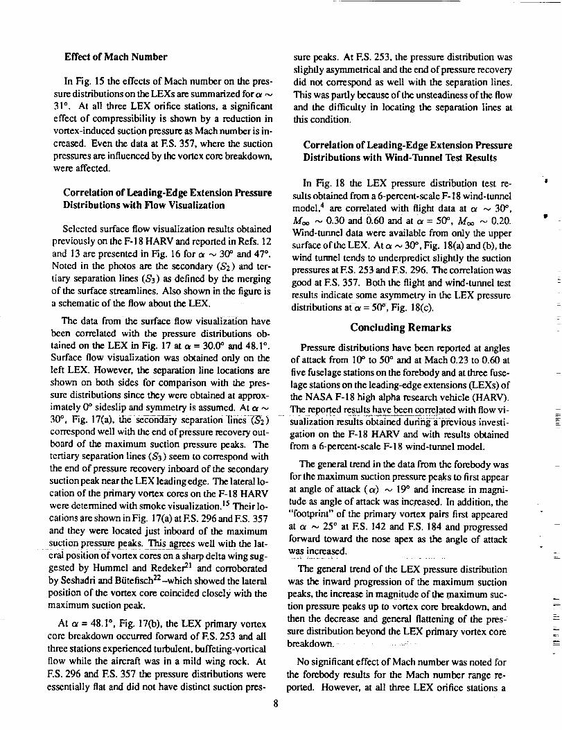
Effect of Mach Number
In Fig. 15 the effects of Mach number on the pres-
sure distributions on the LEXs are summarized for a ,,_
31 °. At all three LEX orifice stations, a significant
effect of compressibility is shown by a reduction in
vortex-induced suction pressure as Mach number is in-
creased. Even the data at ES. 357, where the suction
pressures are influenced by the vortex core breakdown,were affected.
Correlation of Leading-Edge Extension PressureDistributions with Flow Visualization
Selected surface flow visualization results obtained
previously on the F- 18 HARV and reported in Refs. 12
and 13 are presented in Fig. 16 for ot -,_ 30 ° and 47 °.
Noted in the photos are the secondary ($2) and ter-
tiary separation lines ($3) as defined by the merging
of the surface streamlines. Also shown in the figure isa schematic of the flow about the LEX.
The data from the surface flow visualization have
been correlated with the pressure distributions ob-
tained on the LEX in Fig. 17 at o_= 30.0 ° and 48.1 °.
Surface flow visualization was obtained only on the
left LEX. However, the separation line locations are
shown on both sides for comparison with the pres-
sure distributions since they were obtained at approx-
sure peaks. At F.S. 253, the pressure distribution was
slightly asymmetrical and the end of pressure recovery
did not correspond as well with the separation lines.
This was partly because of the unsteadiness of the flow
and the difficulty in locating the separation lines atthis condition.
Correlation of Leading-Edge Extension PressureDistributions with Wind-Tunnel Test Results
In Fig. 18 the LEX pressure distribution test re-
suits obtained from a 6-percent-scale F- 18 wind-tunnel
model, 4 are correlated with fl!ght data at o_ ,,_ 30 °,Moo ,'_ 0.30 and 0.60 and at oc = 51Y', Moo ,-_ 0.20.
Wind-tunnel data were available from only the upper
surface of the LEX. At ot -,_30 °, Fig. 18(a) and (b), the
wind tunnel tends to underpredict slightly the suction
pressures at ES. 253 and ES. 296. The correlation was
good at F.S. 357. Both the flighi and Wind-tunnel test
results indicate some asymmetry in the LEX pressure
distributions afo_ = 50% Fig. 18(c).
Concluding Remarks
Pressure distributions have been reported at anglesof attack from lff' to 50 ° and at Mach 0.23 to 0.60 at
five fuselage stations on the forebody and at three fuse-
lage stations on the leading-edge extensions (LEXs) of
the NASA F-18 high alpha research vehicle (HARV).imately 0 ° sideslip and symmetry is assumed. At a ,,_ The reported results have been correlated with flow vi-
30 °, Fig. 17(a), the secondary separation lines (,5'2) sualizati0nresultsobtainedduringa previous investl-
correspond well with the end of pressure recovery out- gation on the F-18 HARV and with results obtainedboard of the maximum suction pressure peaks. The
tertiary separation lines (S3) seem to correspond with
the end of pressure recovery inboard of the secondary
suction peak near the LEX leading edge. The lateral lo-
cation of the primary vortex cores on the F-18 HARVwere determined with smoke visualization. 15Their lo-
cations are shown in Fig. 17(a) at ES. 296 and ES. 357
and they were located just inboard of the maximum
suction pressure peaks. This agrees well with the lat-
eral position of vortex cores on a sharp delta wing sug-gested by Hummel and Redeker 21 and corroborated
by Seshadri and Btitefisch22-which showed the lateral
position of the vortex core coincided closely with the
maximum suction peak.
At o_= 48.1 °, Fig. 17(b), the LEX primary vortexcore breakdown occurred forward of ES. 253 and all
three stations experienced turbulent, buffeting-vortical
flow while the aircraft was in a mild wing rock. At
ES. 296 and ES. 357 the pressure distributions were
essentially flat and did not have distinct suction pres-
from a 6'percent-scale F-18 wind-tunnel model.
The general trend in the data from the forebody was
for the maximum suction pressure peaks to first appear
at angle of attack (a) ,-_ 19° and increase in magni-
tude as angle of attack was increased. In addition, the
"footprint" of the primary vortex pairs first appeared
at ot _ 256 at ES. i42 and ES. 184 and progressed
forward toward the nose apex as the angle of attackwas increased.
The general trend of the LEX pressure distribution
was the inward progression of the maximum suction
peaks, the increase in magnitude of _ maximum suc-
tion pressure peaks up to vortex core breakdown, and
then the decrease and general flattening of the pres-
sure distribution beyond the LEX primary vortex corebreakdo_.
No significant effect of Mach number was noted for
the forebody results for the Mach number range re-
ported. However, at all three LEX orifice stations a
8
|
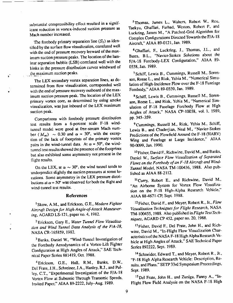
substantial compressibility effect resulted in a signif-
icant reduction in vortex-induced suction pressure asMach number increased.
The forebody primary separation line (S'1) as iden-
tified by the surface flow visualization, correlated well
with the end of pressure recovery leeward of the max-
imum suction pressure peaks. The location of the lam-
inar separation bubble (LSB) correlated well with the
kinks in the pressure distribution curves windward of
the maximum suction peaks.
The LEX secondary vortex separation lines, as de-
termined from flow visualization, corresponded well
with the end of pressure recovery outboard of the max-
imum suction pressure peak. The location of the LEX
primary vortex core, as determined by using smoke
visualization, was just inboard of the LEX maximum
suction peak.
Comparisons with forebody pressure distribution
test results from a 6-percent scale F-18 wind-
tunnel model were good at free-stream Mach num-
ber (Moo) ,-_ 0.30 and o_ = 30 °, with the excep-
tion of the lack of footprints of the primary vortex
pairs in the wind-tunnel data. At ot = 50 °, the wind-
tunnel test results showed the presence of the footprints
but also exhibited some asymmetry not present in the
flight results.
On the LEX, at oe ,-_ 300, the wind tunnel tends to
underpredict slightly the suction pressures at some lo-
cations. Some asymmetry in the LEX pressure distri-
butions at o_= 50 ° was observed for both the flight andwind-tunnel test results.
References
1Skow, A.M., and Erickson, G.E., Modern Fighter
Aircraft Design for High-Angle-of-Attack Maneuver-
ing, AGARD LS-121, paper no. 4, 1982.
2Erickson, Gary E., Water Tunnel Flow Visualiza-
tion and Wind Tunnel Data Analysis of the F/A-18,NASA CR- 165859, 1982.
3 Banks, Daniel W., "Wind-Tunnel Investigation of
the Forebody Aerodynamics of a Vortex-Lift Fighter
Configuration at High Angles of Attack," SAE Tech-
nical Paper Series 881419, Oct. 1988.
4Erickson, G.E., Hall, R.M., Banks, D.W.,
Del Frate, J.H., Schreiner, J.A., Hanley, R.J., and Pul-
ley, C.T., "Experimental Investigation of the F/A-18
Vortex Flow at Subsonic Through Transonic Speeds,
Inyited Paper," AIAA 89-2222, July-Aug. 1989.
5Thomas, James L., Waiters, Robert W., Reu,
Taekyu, Ghaffari, Farhad, Weston, Robert P., and
Luckring, James M., "A Patched-Grid Algorithm for
Complex Configurations Directed Towards the F/A- 18
Aircraft," AIAA 89-012I, Jan. 1989.
6Ghaffari, E, Luckring, J., Thomas, J.L., and
Bates, B.L., "Navier-Stokes Solutions about the
F/A-18 Forebody-LEX Configuration," AIAA 89-
0338, Jan. 1989.
7 Schiff, Lewis B., Cummings, Russell M., Soren-
son, Reese L., and Rizk, Yehia M., "Numerical Simu-
lation of High-Incidence Flow over the F-18 Fuselage
Forebody," AIAA 89-0339, Jan. 1989.
SSchiff, Lewis B., Cummings, Russell M., Soren-
son, Reese L., and Rizk, Yehia M., "Numerical Sim-
ulation of F-18 Fuselage Forebody Flow at High
Angles of Attack," NASA CP-10038, vol. 1, 1989,
pp. 345-359.
9 Cummings, Russell M., Rizk, Yehia M., Schiff,
Lewis B., and Chaderjian, Neal M., "Navier-Stokes
Predictions of the Flowfield Around the F- 18 (HARV)
Wing and Fuselage at Large Incidence," AIAA
90-0099, Jan. 1990.
t° Fisher, David F., Richwine, David M., and Banks,
Daniel W., Surface Flow Visualization of Separated
Flows on the Forebody of an F-18 Aircraft and Wind-
Tunnel Model, NASA TM-100436, 1988. Also pub-lished as AIAA 88-2112.
l l Curry, Robert E., and Richwine, David M.,
"An Airborne System for Vortex Flow Visualiza-
tion on the F-18 High-Alpha Research Vehicle,"
AIAA 88-4671-CP, Sept. 1988.
12Fisher, David F., and Meyer, Robert R., Jr., Flow
Visualization Techniques for Flight Research, NASA
TM- 100455, 1988. Also published in Flight Test Tech-
niques, AGARD CP 452, paper no. 20, 1988.
t_Fisher, David F., Del Frate, John H., and Rich-
wine, David M., "In-Flight Flow Visualization Char-
acteristics of the NASA F- 18 High Alpha Research Ve-
hicle at High Angles of Attack," SAE Technical Paper
Series 892222, Sept. 1989.
14Schneider, Edward T., and Meyer, Robert R., Jr.,
"F-18 High Alpha Research Vehicle: Description, Re-
suits, and Plans," SETP 33rd Symposium Proceedings,
Sept. 1989.
15Del Frate, John H., and Zuniga, Fanny A., "In-
Flight Flow Field Analysis on the NASA F-18 High
9

AlphaResearchVehicleWithComparisonstoGroundFacilityData,"AIAA-90-0231,1990.
16Whitmore,StephenA., Moes, Timothy R., and
Larson, Terry J., Preliminary Results From a Sub-
sonic High Angle-of-Attack Flush Airdata Sensing
(HI-FADS) System: Design, Calibration, and Flight
Test Evaluation, NASA TM- 101713, 1990.
17polhamus, Edward C., A Review of Some
Reynolds Number Effects Related to Bodies at High
Angles of Attack, NASA CR-3809, 1984.
lSRichardson, Norman R., and Pearson, Albin
O., Wind-Tunnel Calibrations of a Combined Pitot-
Static Tube, Vane-Type Flow-Direction Transmitter,
and Stagnation-Temperature Element at Mach Num-
bers From 0.60 to 2.87, NASA TN D-122, 1959.
19peake, D.J., Fisher, D.F., and McRae, D.S.,
"Flight, Wind Tunnel, and Numerical Experiments
with a Slender Cone at Incidence," AIAA .lournal,
vol. 20, no. 10, Oct. 1982, p. 1338.
2oHall, Robert M., "Influence of Reynolds Number
on Forebody Side Forces for 3.5-Diameter Tangent-
Ogive Bodies," AIAA-87-2274, Aug. 1987.
21Hummel, D., and Redeker, G., Eaperimental
Determination of Bound Vortex Lines and Flow in
the Vicinity of the Trailing Edge of a Slender Delta
Wing, NASA Technical Translation, NASA TT F-15,
012, 1973.
22Seshadri, S.N., and Btitefisch, Karl-Aloys, "Eval-
uation of LDA 3-Component Velocity Data on a 65°
Delta Wing at M = 0.85 and First Results of an Anal-
ysis," DFVLR-FB 89-19, Mar. 1989.
"W
Fig. 1 F- 18 HARV
EC89 0096-214
10
ORIGINAL PAGE IS
OF POOR QUALrl"Y

Nose static
pressure rin
LEX pressureorifices
F.S. 70 (x/_ = 0.015) : :
F.S. 85 (x/_ = 0.038)
F.S. 107 (xL_ = 0.071)
F.S. 142 (x/,_ = 0.126)
F.S. 184 (x/_ = 0.190)
F.S. 253 (x/,_ =
F.S. 296 (x/,e = 0.361
F.S. 357 (x/_ = 0.454)
Fig. 2 Forc_)dy and LEX pressure measuremenl stations.
900298
11

180° F.S. 184
d max = 49.30 in.
°o'o;='n90° _ 270 ° s = 28.97 in.
-y <v--_ _y
0o180° F.S. 142
39.25 in. Wd max =
90° _ 270°
F.S, 296 ....
0o180 °
90° (_ 270°
0o
0
180°
270o
0o
F.S. 107 -Y
d max = 29.82 In. _s_d min = 29.80 in.
F.S. 85
d = 20.42 in.
180 ° F.S. 70
900.0 270 ° d = 11.07 in.
0 ° 900299
(a) Forcbody circumfcrcnlial angle.
•...-_ y
_ y .,_--
F.S. 253s = 14.84 in.
--_y
W(b) LEX spanwise position.
9OO300
Fig. 3 Cross sections of pressure measurement stations and orifice orientation, looking aft.
12
t

ORIGINAL PAGE
BLACK AND WHITE PHOTOP_RAPk
(a) Forcbxxly locations.
(b) LEX locations.
Fig. 4 Locations of protusions near pressure measurement stations.
13 ORIGINAL PAGE IS
OF POOR QUALITY

__9 12.719 In. --_
.281 In. _ I
_'' --- ' __-I--I-_I-_-P--, _ ,- o
_-- 7.906ln.-__ II _Angle-of-attackvane I n._
Static-pressure orifices ill \ 6.781 i 6.781 in._
•opv,ew l-- 23.094 in. >I I I
= 32.625 In.
Upper su_
_71,-_--_-, ___.:-t27.250 in. >
Angle-of-sideslip vane
Side view L_J_ 8.750 in.
(a) Drawing of NACA airdata probe, right winglip.
Flear view
9OO303
Probe body
24.4 in.
Alignment fins\
Gimbal --_\
Gooseneck-15 °
Angle-of-attack vane
(b) Pholo of swiveling-hcad airdala probe, lcft wingtip.
Fig. 5 Airdata probes mountcd on F-I 8 HARV wingtips.
14
ORIGINAL PAGE IS
OF POOR QUALITY
z

-.5
0.o-o-o-_ _-o-o..o_
Moo c_ 13 Re_ (10 6)
0.37 10.0 0.1 15.00.32 15.2 0.1 12.70.30 19.7 -0.1 11.5
=0 ..............................
0 60 120 180 240 300 360
O, deg, F.S. 70
-.5
Cp 0
.50 60 120 180 240 300 360
O, deg, F.S. 85
I
0 60 120 180 240 300 360
O, deg, F.S. 107
-.5
Cp 0
.50 60 120 180 240 300 360
e, deg, F.S. 142
0 60 120 180 240 300 360
e, deg, F.S. 1849OO305
(a) o_= 10.0 °, 15.2 °, and 19.7°; Moo _ 0.35.
Fig. 6 Effect of angle of attack on forcbody surface static prcssure cocfficienLs on thc F-18 IIARV at low speed.
15

-1.0
-.5
Cp 0
.5
1.00 60 120 180 240
O, deg, F.S. 70
300 360
Moo (x _ Re_ (10 6)
0.25 25.8 0.0 10.80.26 30.0 - 0.1 10.30.23 34.3 0.3 9.1
-1.0
Cp 0
60 120 180 240 300 360
e, deg, F.S. 85
....... . ........ =., ...........
0 60 120 180 240 300 360
e, deg, F.S. 107
-1.0
Cp 0
.5 _
1_0 i ............... _==_ .......... • ..........
0 60 120 180 240 300 360 0 60
O, deg, F.S. 142
(b) _ = 25.8 °, 30.0 °, and 34.3°; M_ _ 0.25.
120 180 240 300 360
0, deg, F.S. 184900306
Fig. 6 Continucd.
16

Cp
-2.0
-1.5
-1.0
--.5
0
.5
1.00
r /i............
60 120 180 240 300 360
G, deg, F.S. 70
M (X
---.o--- 0.25 39.3 - 0.1--"0-- 0.23 45.4 0.0
0.23 50.0 0.0
Re_ (10 6 )
8.36.96.6
Cp
-1.5
Cp ,
.:/ -°0 .... • ........................... J ...........
0 60 120 180 240 300 360 0 60 120 180 240 300 360
O, deg, F.S. 142 O, deg, F.S. 184
(c) ot = 39.3 °, 45.4 °, and 50.0°; M_ ,'_ 0.25.
Fig. 6 Concludcd.
9003O7
17
Cp
-1.5
-1.0
-.5
0
I
.5] -_
1.00 60 120 180 240 300 360
0, deg, F.S. 70
Moo (x [3
--o-- 0.60 9.9 - 0.3---o-- 0.60 14.9 0.0
0.60 19.1 -0.2
Re_ (10 6 )
25.423.025.4
Cp
-1.0
-.5
0
.5 --
1.0 ............................0 60 120 180 240 300 360-
e, deg, F.S. 85
d _=-_-_ _-r : -- -----#-
......... J .........
0 60 120 180 240 300 360
e, deg, F.S. 107
Cp
-1.5k--
-1.0
-.5
1.060 120 180 240 300 360
0, deg, F.S. 142
m
0 60 120 180 240 300 360
G, deg, F.S. 184
(a) oL= 9.9 °, 14.9 °, and 19.1 °
90O308
Fig. 7 Effect ofangle of attack on forcbody surface slatic pressure coefficients on the F-I 8 HARV at Moo '--, 0.60.
18
-1.5=k
lOCp 0
• i !.0 ..... i .......... , ................
0 60 120 180 240 300 360
e, deg, F.S. 70
Cp
-1.5
-1.0
w.5
0
.5
k
I
L
.0 ..... J _" ........ i ...............
0 60 120 180 240 300 360
e, deg, F.S. 85
Moo 0_ _ Re_ (10 6 )
---o-- 0.60 25.6 0.2 24.20.60 30.5 -0.3 12.70.60 38.5 0.2 12.7
0 60 120 180 240 300 360
O, deg, F.S. 107
-1.5
-1.0
--.5
Cp
k i
A I
1.0 ..................................0 60 120 180 2_ 300 360
e, deg, F.S. 142
_c
t'
..... L ..........................
0 60 120 180 240 300 360
O, deg, F.S. 184900309
(b) c_= 25.5 °, 30.5 °, and 38.5 °.
Fig. 7 Concluded.
19

-1.0
-.5
Cp 0
.5
1.00
"oo0.60 30.5 - 0.3 12.70.50 30.8 - 0.6 10.70.40 31.0 - 1.7 8.80.26 30.0 - 0.1 10.3
Values of Re d. (10 6)
o;6o0.500.4O0.26
60 120 180 240 300 360
oo F.S. 70 F.S. 85 F.S. 107 F.S. 142 F.S. 184
1.78 3.28 4.79 5.44 6.841.50 2.77 4.04 4.59 5.721.21 2.23 3.25 3.77 4.801.47 2.71 3.96 4.41 5.62
e, deg, F.S. 70
-1.0
Cp 0 /
1.0 ..................0 60 120 180 240 300 361
e, deg, F.S. 85
-1.0
0 60 120 180 240 300 360
e, deg, F.S. 107
Cp 0
"5 i ............... k
0 60 120 180 240 300 360 0 60 120 180 240 300 360
e, deg, F.S. 142 e, deg, F.S. 184900310
Fig. 8 Effect of Math number on forclx)dy surface stalic pressure coefficients on the F-18 HARV, o__ 31 °.
2O

(a) c_,-_ 30 °.
Fig. 9 Surface flow visualization on F- 18 HARV forebody.
Reattachment, R
iiii_Secondary vortex_i-J_!Ji-j!separation line, S 2 .....
(b) 1/4 view, c_ _ 47 °.
Fig. 9 Continued.
21
ORIGINAL PAGE IS
OF POOR QUALITY

(c) Closcup of nosecone, o_,-_ 47 °.
Fig. 9 Concluded.
ORIGINAL PAGE ISOF POOR QOALITY
22

-1.0
-.5
Cp 0
.5
1.00
..... I ..... ! ..... I ..... I ..... I .....
60 120 180 240 300 360
8, deg, F.S. 70
Moo (x
---0-- 0.26 30.0 - 0.1
Re_ (10 6 )
10.3
Values of Re d- (10 6)
F.S. 70 F.S. 85 F.S. 107 F.S. 142 F.S. 184
1.47 2.70 3.94 4.47 5.62
-1.0
-.5
Cp 0
.5
1.00
-1.0
..... ! ..... ! ..... i ..... I ..... i .....
..... | ..... | ..... | ..... ! ..... ! .....
60 120 180 240 300 360
0, deg, F.S. 85
..... i ..... ! ..... ! • ' "'_=; I ..... I .....
0.... I ..... l ..... I ..... i .... llillli
60 120 180 240 300 360
e, deg, F.S. 107
Cp
-.5
0
.5 ..... I • , . . , [ ..... l ..... I • i i I_]LJ t=J.
0 60 120 180 240 300 360
6, deg, F.S. 142
$1_1 I I I I_S1
$2_ R _ S2..... I ..... I ..... I ..... I...llllllll
0 60 120 180 240 300 360
e, deg, F.S. 184
9O0314
(a) _ = 30.0°; M_ = 0.26.
Fig. 10 Comparison of forebody surface static pressure coefficients with flow visualization results on theF-18 HARV.
23

-2.0
-1.5
-1.0
Cp -.5
0
.5
1.00 60 120 180 240 300 360
0, deg, F.S. 70
M oo (_ I_ Re _ (10 6)
•--o--. 0.23 48.1 0.0 6.9
Values of Re d, (10 6)
F.S. 70 F.S. 85 F.S. 107 F.S. 142 F.S. 184
0.68 1.26 1.84 2.29 2.87
-2.0 ..... _..............................
-1.5
-1.0
Cp -.5
0
.5
1.0 ...................................0 60 120 180 240300 360
e, deg, F.S. 85
0 60 120 180 240 300 360
e, deg, F.S. 107
Cp
-1.5
-1.0
--.5
0
.5
1.00
..... q ..... i ..... • ..... , ..... , .....
( $2_ L_$2
60 120 180 240 300 360
0, deg, F.S. 142
II II
s-/Is2-] s21
0 60 120 180 240 300 360
O, deg, F.S. 184
Co) ot =48.1°; Moo = 0.23.
Fig. 10 Concluded.
900315
24

- 1.0
m.5
Cp
vo'u-o,.%(lO_) . _ _ .._(lO6)F.S. 107 F.S. 142 F.8.184 1 O Model 0.30 30.0 0.0 1.40
Model 0.,54 0.61 0.76 _ Flight 0.26 30.0-0.1 10.3
Flght 3.94 4.47 5.62
' \o�.5 - .......................................... _;• ..... "
0 60 120 180 240 300 360 0 60 120 180 240 300 360 0 60 120 180 240 300 360
8, deg, F.S. 107 0, deg, F.S. 142 0, deg, F.S. 184900316
(a) o_= 3010°i M= ~ 0.30.
- 1.0
_,5
P0
Values of Red.(106 _
F.S. 107 F.S. 142 F.S. 1_11
0.73
Model 0.51 0.58 8.83F ght 4.81 5.44
0 Model 0.60 30.0 0.0 1.33
Right 0.60 30.5 -0.3 12.7
,- /..,\i •
0 60 120 180 240 300 360 0 60 120 180 240 300 360 0 60 120 180 240 300 360
0, deg, F.S. 107 8, deg, F.S. 142 8, deg, F.S. 184900317
(b) o_ ,-, 30°; Moo = 0.60.
- 2.0
Values of Re d.(10 5 )
F.S. 107 F.S. 142 F.S, 184 1
Model 0.25 0.31 0.39
F ght 1.72 2.15 2.70
.=, _, p .._(10_)O Model 0.20 50.0 0.0 0.96
Flight 0.23 50.0 0.0 8.6
- 1.5 -_
-1.o /"_ r "
t
.5,,/
1.0 ...............0 60 120 180 240 300 360
0, deg, F.S. 107
0 60 120 180 240 300"360 0 60 120 180 240 300 360
8, deg, F.S. 142 e, deg, F.S. 184900318
(c) o_ = 50.0°; Moo _, 0.20.
Fig. 11 Comparison of flight- and wind-tunnel-measured surface static pressure coefficients on the F-18 HARV
forebody.
25

ORIGINAE PAGE
BLACK AND WHITE PHOTOGRAPH
(a) . = 20.0* and/9 = (7.
(b) o_= 29.8 ° and/9 = 0.2".
(c) o_= 42.5 ° and/9 = 0.8*
Fig. 12 W'mgtip view of smoke flow visualization on F-18 HARV LEX.
26
ORIGINAL PAGE IS
OF POOR QUALITY'

_ 13.._(lO_)0.37 10.0 0.1 15.0
0.32 15.2 0.1 12.7
0.30 19.7 -0.1 11.5
Solid symbols - lower surface
-1 -.6 -.2 .2 .6 1 -1 -.6 -.2 .2 .6 1 -1 -.6 -.2 .2 .6 1
y/s, F.S. 253 y/s, F.S. 296 y/s, F.S. 35790O319
(a) o_= 10.0 °, 15.2 °, and 19.7% Moo _ 0.35.
-4
cp _-1
1-1 -.6 -.2 .2 .6
y/s, F.S. 253
(b)
0.25 25.8 0.0 10.8
0.26 30.0 -0.1 10.3
0.23 34.3 0.3 9.1
Solid symbols - lower surface
-1 -.6 -.2 .2 .6 1 -1 -.6 -.2 .2 .6 1
y/s, F.S. 296 y/s, F.S. 357900320
oe = 25.8 °, 30.0", and 34.3°; Moo -,_ 0.25.
-4
- _ _ .._ (1o6)0.25 39.3 -0.1 8.3
0.23 45.4 0.0 5.9
0.23 50.0 0.0 6.6
Solid symbols - lower surface
Cp _ g
0
1-1 o.6 -.2 .2 .6 1
y/s, F.S. 253
-1 -.6 -.2 .2 .6 1 -1
y/s, F.S. 296
Fig. 13
-.6 -.2 .2 .6 1
y/s, F.S. 357900321
(c) o_= 39.4 °, 45.4 °, and 50.0°; Moo "- 0.25.
Effect of angle of attack on LEX surface static pressure coefficients on the F-18 HARV at low speed.
27

-2
1 ""
-1 -.6 -.2 .2 .6 1 -1 -.6 -.2 .2 .6 1
y/s, F.S. 253 y/s, F.S. 296
(a) a = 9.9 °, 14.9 °, and 19.1 °.
'_ p _,_0o_)---e-- 0.60 9.g - 0,3 25.4
---e--- 0.60 14.g 0.0 23.0
0.60 Ig.1 -0.2 25.4
Solid symbols - lower surface
"b,,,_ _ 4 n, _ _,a
-1 -.6 -.2 .2 .6 1
y/s, F.S. 357900322
-3
C p -1
0 • '
a,..,.,._.-..-.-. ,a z,_ :Z:::_ i_lp _S===l z .=_11=_1,1
-1 -.6 -.2 .2 .6 1 -1 -.6 -.2 .2 .6 I -1
y/s, F.S. 253 y/s, F.S. 296
(b) ol = 25.6 °, 30.5% and 38.5 °.
_ p _z(,o _)0.60 25.6 0.2 24.2
0.60 30.5 - 0.3 12.7
---b-- 0.60 38.5 0.2 12.7
Solid symbols - lower surface
',%,,.../
-.6 -.2 .2 .6 1
y/s, F.S. 357900323
Fig. 14 Effect of angle of attack on LEX surface static pressure coefficients on the F-18 HARV at M_ _ 0.60.
-3
-2
Cp -I
0
1-I -.6 -.2 .2 .6 1
. _ _ .._(,0_0.60 30.5 -0.3 12.7
0.50 30.8 - 0.6 10.7
..... 0.40 31,0 - 1.7 8.8
0.26 30.0 - 0.1 10.3
Solid symbols - lower surface
_-_ "_-- _ _ r • I_ _II_ _ _ Ir._ _
-I -,6 -,2 .2 ,6 1 -I -,6 -,2 .2 .6 1
y/s, F.S. 253 y/s, F.S. 296 y/s, F.S. 357 900324
Fig. 15 Effect of Mach number on LEX surface static pressure coefficients on the F-18 HARV at ot _ 31.0%
28

ORIGINAL PAGE
13LACK AND WHITE PHOTOGRAPH
(a) _ ,-,, 30 °.
F.S. 357
(b) _ _ 47 °.
Fig. 16 Surface flow visualizalion on left LEX of F- 18 HARV.
29
ORIGINAL PAGE IS
OF POOR QUALITY

Cp
-4
-3
-2
-1
0
. . . , - , . , - . . , - . . , - . .
5 3 S3-d
-1 -.6 -.2 .2 .6 1
y/s, F.S. 253
-1
.. _ _ .._(_o6)o_ ._ -ol _o_8olld m/mbols - lower 8urfJ_e
Vortex positions abovo LEX Vortex positions above LEX
_ (R.,.15) _ _ (R.,.15) _
. . . , . . o • . L_ L_ L. • L . .
-.6 -.2 .2 .6y/s, F.S. 296
' ...... • ....... J ....... • ....... • .......
-1 -.6 -.2 .2 .6y/s, F.S. 357
9OO327
(a) oe = 30.0°; Mao = 0.26.
Cp
.4 - • - 0 - • - , - • - • - - - o - - -
lt s. ..j-1 -.6 -.2 .2 .6 1
y/s, F.S. 253
.** _ 13.._(10_)0.23 48.1 0.0 6.9
Solk_ |ymbol| - lower 8urbce
. . . , . . . , • . . . . , . , - . .
-.6 -.2 .2 .6 -1 -.6 -.2 .2
y/s, F.S. 296 y/s, F.S. 357
II II
D.:, ::I.6
9OO328
(b) _=48.1°; Moo = 0.23.
Fig. 17 Comparison of LEX surface static pressure coefficients with flow visualization results on the F-] 8 HARV.
30

Cp
-3
-2
-1
0
1-1 -.6 -.2 .2 .6 1
y/s, F.S. 253
0 Model
FIIgM
- - - Lower surface
1 -1-1 -.6 -.2 .2 .6y/s, F.S. 296
(a) c_ = 30.0°; Moo _ 0.30.
_ _ ,._(lo 6)0.3O 30.0 0.0 1.40
0.26 30.0 - 0.1 10.3
.e \¢ -
-.6 -.2 .2 .6 1
y/s, F.S. 357
Cp
-3
•e"_, e'_o .. • e'_o,
_ _ ,._(lg ")o .ado, gig 300 0.0 1_
- - - Flight 0.60 30.5 - 0.3 12.7
- - - Lower surface
eeoee ¸
• i
0 ...........
1-1 -.6 -.2 .2 .6 1 -1 -.6 -.2 .2 .6 1 -1 -.6 -.2 .2 .6 1
y/s, F.S. 253 y/s, F.S. 296 y/s, F.S. 357900330
(b) o_ _ 30°; Moo = 0.60.
-3
C p -1
_ .._ (,oe)50.0 0.0 0.96
50.0 0.0 6.6
0 Model 0.20
-- Flight 0.23
- - - Lower surface
0 .....
1 - - ""-°- ""-1 -.6 -.2 .2 .6 1 -1 -.6 -.2 .2 .6 1 -1 -.6 -.2 .2 .6 1
y/s, F.S. 253 y/s, F.S. 296 y/s, F.S. 357900331
(c) _ = 50.0°; Moo ,_ 0.23.
ml ee
Fig. 18 Comparison of flight- and wind-tunncl-mcasurcd LEX surface static prcssure cocfficients on thc F-18.
31
ORiGIN._,L PAGE IS
OF POO_ _)tJALITY

Na_o_dAoron"u_ _md
_paoe Admin_,ti_on
1. ReportNo.NASA TM-101724
4. TitleandSubtitle
Report Documentation Page
2. GovernmentAccessionNo. 3. Reclpient'sCatalog No.
5, ReportDate
F-18 High Alpha Research Vehicle Surface Pressures: Initial
In-Flight Results and Correlation With Flow Visualization andWind-Tunnel Data
7. Author(s)David F. Fisher (Ames Research Center, Dryden Flight Research Facility,
Edwards, California)
Daniel W. Banks (Langley Research Center, Hampton, Virginia) David M.
Richwine (PRC Systems Services, Edwards, California)
9. PerformingOrganization Name and Address
NASA Ames Research Center
Dryden Flight Research FacilityP.O. Box 273, Edwards, California 93523-0273
12.Sponsoring AgencyName andAddress
National Aeronautics and Space Administration
Washington, DC 20546-3191
August 1990
6. PerformingOrganization Code
8. PerformingOrganization Report No.
H-1633
10.Work Unit No.
RTOP 505-60-21
11. Contractor Grant No.
13.Type of Reportand PeriodCoveredTechnical Memorandum
14.Sponsoring AgencyCode
15.SupplementaryNotes
Prepared as AIAA 90-3018 for presentation at the AIAA 8th Applied Aerodynamics Conference, Portland, Oregon,
August 20-22, 1990.
16.Abstract
Pressure distributions measured on the forebody and the leading-edge extensions (LEXs) of the NASA F-IS high alpha
research vehicle (HARV) have been reported at i0 ° to 50 ° angle of attack and at Mach 0.20 to 0.60. The results have been
correlated with HARV flow visualization and 6-percent scale F- 18 wind-tunnel-model test results. The general trend in the data
from the forebody was for the maximum suction pressure peaks to first appear at angle of attack (_) ~ 19° and increase in
magnitude with angle of attack. The LEX pressure distribution general trend was the inward progression and increase in
magnitude of the maximum suction peaks up to vortex core breakdown and then the decrease and general flattening of thepressure distribution beyond that. No significant effect of Mach number was noted for the forebody results. However, asubstantial compressibility effect on the LEXs resulted in a significant reduction in vortex-induced suction pressure as Mach
number increased. The forebody primary and the LEX secondary vortex separation lines, from surface flow visualization,
correlated well with the end of pressure recovery, leeward and windward, respectively, of the maximum suction pressure peaks.
The flight to wind-tunnel correlations were generally good with some exceptions.
17. Key Words (Suggested by Author(s))
F-18; Flow visualization; High angle of attack; Laminar
separation bubble; Pressure distribution;
Separation; Vortex flow
18.DistributionStatement
Unclassified-Unlimited
Subject category 02
19. Security Classif.(ofthisreport)Unclassified
20. Security Classif.(of this page)Unclassified
2t. No.of Pages34
22. Price
A03
_ASAFORM 1626 OCTSS Forsale by theNationalTechnicalInformationService,Springfield,Virginia 22161-2171