Embed Size (px)
Citation preview

I
I II cms mswxc Ewscw es comms es rm:6
uomws nw suse num TO vmmxcu LOADS6
bv
Kenneth Woodrow Cegan
Thesis submitted to the Graduate Faculty of the
Virginia Polytechnic Institute
in candidaey fer the degree ofU
msrna or scxmcsm
Aacmwscauun smoxxmeame
APPRGVEM APPROVED:/_ I
gv VVVV y " Te VtAugust, 1961
Blacksburg, Virginia
I

/F‘>‘b“¢/AL
LCOMTEMTS {
Page
I, Introduction,,,,,,,,,•••,•,,,,,,,,,,••,,,•,,,,,,,•, 4II, Preceeding Tneses,,,,,,,,,,,,,,,,,,,,,,,,,,,,,,,,,, 5
III, Derivatio of Plate Formu1as,•,,,,,,,,,,,,,,,,,,,,, 7
IV, Prellmlnary Considerations in Analytical So1utlon,, 15V, The Redistribution of Stresses,,,,,,,,,.,,,,,,,,,,, 14VI, Review of Westergaard's Artic1e,,,,,,,,,,,,,,,,,,,, 16
VII, Review ot T1moshenko*s Method,,,,,,,,,,,,,.,,,,,,,, 16
VIII, Comparison of Resulte,,,,,,,•,,,,,•,,•,,,,,,,,,,,,, 20
IX, 29X, Acknow1edgements,,,,,•,,,,,,,,,,,,,,,,,,,,,,,,,,,,, 52
XI, Literature Clted,,,,,,•,,,,,•,,,,,,,,,,,,,,,,,,,,,, 55
FIGURESPage
{1, Plan of Slab, Shoing Load Points and Location of I
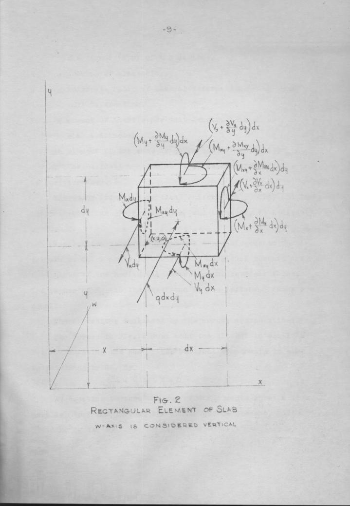
{ Strain Roeettes,,,,,,,,,,,,,,,,,,,,,,,,,,,,,•,,,,,,,,, 62, Rectangular Element of S1ab,,,,,,,,,,,,,,,,,,,,,,,,•,, 9
{ 5, Single Panel of S1ab,,,,,,,•,,,,,,,,,,,,,•,•,,,,,,,,,, 19 {4, Conditions of Loading Around Pane1,,,,,,,,,,,,,,,,,,,,195,
Theoretical Moment Coefficiente along Edge,,,,,,,,,,,, 216, Theoretical Moment Ccefficients across Edge,,,,,,,,,,, 227, Theoretlcal Moment Coefflcients across Center Line,,,, 22
L I

Page
8. Theoretieal Moent Coefflcienta along Center Line••• 23
9. Left Dlagram: Theoretieal Moment CoefficientsQCPOSS D18; @01181
Right Dlagram: Tneoretleal Moment Coefficlente
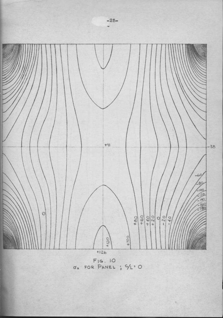
10, for Panel; C/L ; O..••••••••••„„.••••••••..••••••„ 25
ll, for Panel; C/L = 0•lO••„..••.••„•„•„•..•.•„„...••• ZG12, far Panel; Experimental Reeulte••.•„.•„•„„••••„••. 27

N "'N
I, INTRODUCTION
The ever-increasing scarcity sf many structural mater-
ials accentuates the need of contlnuing investigations into
the true interaction of stresses in all the components of a
structnral frame, These investigations can save materials,
· both by recognizing the part played by structural elements
hitherto disregarded as being too complex to consider, and
by the resultant reduction of safety factors employed by
the building trades, At the same time lt must be realized
that, for reasons of economy, designers and engineers are
not likely to spend large sums of money for the complex
analyses now·necessary to determine these stress interactions,
when the cost of such analyses cannot be offset by approxi-
mately equal savings in the cost of structural materials,
For these reasons it is desirable tht methods of analysis,
which consider the importance of all the structural compon-
ents of a frame, can be presented to the architect and the
N engineer in such forms trat the analyses can be performed
with reasonable rapidity by the regular members of the design
staff, NOne of the important structural elements which is large-
Nly disregarded in present design procedure is the floor slsb,
both continuous and dlscentinuous, Thß floor slab at present
is generally designed by considering a typlcal strip in floors
N

-5-
which span in one direction. Slabs which span in both direc-
tions have their design rigidly controlle by coe specifica—
tions, which are based on empirical formulas. Little or no
attention is directed to the interaction of etresses between
the slabs, the beams, and the columns. It is the purpose of
this thesis to continue the investigation, begun by E. L.
Miller} of a square slab welded to four columns; comparing
Miller's experimental results with the results of analytical
solutions by N, J. Neilson and H. M, Westergaard, Later
formulas for analytical solutions by S. Timoshenko will also
be presented. It is hoped that the work done in this thesis
f will provide part of s usable basis for further experimentalwork by the Virginia Polytechic Institute's Department of
Architecture.
II• PRECEEDING THESES
Miller's thesis dealt with the loading of a square steel
plate supported on round columns, and with the measurement of
strains produced by the loading. Tha columns were welded to
the plate and were simply supported in countersunk holes at
their lower ends. Results were recorded from readings taken
from SR-4 strain rosettes place at the corners of squares,
i L/6 an a side, in one quadrant of the plate (Fig. l). Four
SR-4 strain gages, ninety degreee apart, were affixed to the 1
top of the adjacent column. The plate was divided into N
1
1
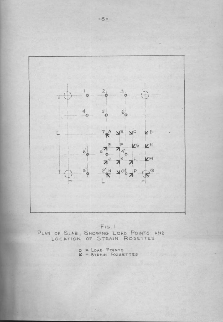

ä -7-> squares, L/4 on a side, and loads of soo0# were applied in
eymmetrical pairs at the corners of the squares; except that
a single sooo# load was applied at the intersection of the
main diagonals, and no loads were applied over the columns
(Fig. l). The readings obtained from these loadlngs were
euperlmposed to obtain approximately the same conditions as
would be ohtained from a uniform load of approxlmately
655psf• An ovcrhang was left on all sides of thß plate.
Unfortunately, no etrain measurements were made on this over-
hang, so its influence on the stresses in the plate, and on
the moments in the column cannot he studied.
In addition to the experimental work done hy Miller and
the data recorded by him, a valuable thesis was presented by
R, J. Kolker? listing a large amount of the literature pub-
lished on the design and analysis of slabs and plates, and
reviewing briefly the literature which was listed. Refer-
ence has been made repeatedly to Kolker's thesis in select-
'
ing articles whlch.bear on the topic of the present thesis.III. DERIVATIOH OF PLATE FORMULASThe derivationa of the plate formulas Vary somewhat
among different authors, but the results are in general
accordance with one another. The derlvatlon presented here 7
follows approximately that of H. M. Westergaardé Qu

-8-
Preliminary considerations used in the derivation are:
(l) the material is homogeneous and isotropic through-
out ,
(2) stress varies linearly with strain,
(5) the neutral axis is a plane (a warped plane during
deflection) at all times half the thickness of the plate be-
neath the upper surface,
(4) the plate is medium thick, 1.6. not so thick that
an appreciahle part of the energy of deformation is contri-
buted hy the vertical stresses, and not so thin that an aggre-
ciable part of the energy is contributed by the plate’s stret-
ching•
The following notations will be used:
x,y ; horizontal rectangular coordinates•
} w g vertical deflectio, positive downward,
I VX • vertical shear per unit length in section perpendi-
cular to x at point (x,y)•I
i Vj g same in section perpendicular to y•
Mx , bending moment per unit length in sectionperpendi-I
cular to x at point (x,y); positive whencausingI
conpression at top and tension at hottom• I
My z same in sectio perpendicular to y,
Mxy = torsional moment per unit length.in sections perpen- Idicular to xy plane at point (x,y); positive when it I
causee shortenings at too along the diagonal through I

I
the corner (x,y) of the element•
E • modulus of elasticity•
v g Poieson's ratio of lateral deformation to lengitud-~
inal deformation•I = moment ot inertia per unit length; 1/12 hä when h is
slab thicknese•An eleent of the slab is taken with<iimensions dx, dy,
and h. The deflection at point (xn?) is measured by w, which
is positive downward•
·The leads are: the vertical uniform load, qdxdy and the
internal vertical sheare, moments, and torsions, as indicatedby Fig, 2•
The vertical ehears and moments are analogoue to verti-
cal anears and momente in beams• The toreional moments arereeultants of the horizontal ehears in the vertical faces•The values of Mxy in the lower and in the left-hand faces are
I
equal.The directione indicated by the arrows are positive•
I The forces in Fig, 2 must hold the element in equili-
I brium. Equating the sum of the vertical components to zero
I and dividing by dx, dy(11Byequating to zero the sum of the momente about a line
parallel to y and through the center of the element, andI dividing by dx, dy
I
I «

I( -13.-
V„ (2)similarly, + ö>< — V' ° (5)
Differentiating (2) and (3) with respect to x and y,
respectively, endl eubetitluting in (1)(4)
Since equations (1) to (4) are equations of equilihriam
only, they do not consider the elastic properties of the
plate• If the elaetic deformetions are considered it is
seen that any type of deformetion can he resolved into (a)
bending in the 1: direction, (b) bending in the y direction,
and/or (c) torsion in the xy-directions• The amounts of
deformation in (a) and (b) are measured by the carvetzxree
..§%_and-§$,_ respectively, just as i$1Nbeas¤s$wa;·1d in (c) hy
the rate of change of the slope ~· é·é··?Q=— äé-äil = ·From the theory of beams, a bending moment Mx, acting
alone, prodnces the curvatures ·· in the x·-direction,
-· ·§$;=-v%—äL in the y•-direction, end no twist, The torsienalcouples prodnce a twist -· which may be determined by
introducing temporarily another system of coordinates,
x',y', making angles of 45° with the system of x,y, The
couples, Mxy, are replaced by an equivalent combination of
ocmples coneieting of the bending moments MX' ; Mxy in the (
x*•direction and My' e •- Mx? in the y*-direction. These (
I
I

-12-
bending; moments produce the curvaturee
8x** El El , $7** E1in terms of which the twiat may be expressed by the trans-
Z T 7- Vformation formale. ·· gs-g-Y = + = •The derivation of the traneformatien Formula follows
from the relationehips2:* g xcoeo(+ y eine
y' ; •·XSl1'lO( + y cogo _
where on • the angle between the two sets of ooordin„ates•
In this case coso • sine; 1/Q . Then.8v;- @1--1- -. äh-E
8x ex' >( 87* ex 8x* Y‘ VE-
8_ 8~¤_¤ 8 <8w>8>«' 8 8w3ev(evÖx'_1_ 8 '_ _[__
but §§‘ Yi , 8’%"Yi”l l-TZ Vi
E-whicheqaals the transformation formale. above when both sidee
of the equation are multipliec?. by minus cme•
I Taking the general case where M , " , and M are allX **1v xypresent, the resultant deformatiohe are—§-”';x~·-
- l°h—-;v-.)~!*-1-«3¤’· EI (5) «P
67* EI__ &ZVJ (Ü
äiä? ElJ)
Solving; (5), (GF), end (7) forcthe moments give,, Ö w w ‘
M·=°<¤-v‘)< 'ä?@“v*7=} (8), uN

MV (9)-..3. - 3%:Mu ‘(1+v> Y) ‘ 119)
If the values of (8), (9) and (10) are substituted in
equation (4) the Lagrange equation for the flexure of plates
results. This is the general ”plate equat1on" used by the
majority of authors on the subject,ä°'w 94,,, 3%) _ 1—v’·dat +Z8>8·ä{‘-Jr ä)/"* ‘ EI
Ct · (ll)
In the solution of the Lagrange equation, Poisson's
ratio is generally taken as zero and thß solution is convert-
ed by
1W = M +‘1/M V‘ = VV ‘ ” (12)w =(•·v‘)w
There ls as yet no general solutio of equation (11).
marcus4 gave a reasonably accurate solution for several
cases, which involved, however, the solution of a number
of simultaneous equations• For some cases Sir Richard
Southwel1's Relaxation methodß is applicable. In all cases
'
a minimum of two boundary conditions is required for a solu-mon. 1g IV. PRELIMINARY CONSIDNRATIONS IN ANALYTICAL SOLUTION M
In attempting an analytical solution of the slab under 1discussion, the following conditions must be recognized:
(1) the plate is rlgidly perpendlcular to the column at the
11

-14-
V polnts of connection, l-e- at the welds, (2) the plate is
free to deflect vertically at all polnts, except at the
columns, (5) the columns are hlnged at the base and rlgldly
supported at the plate-
The dlfflculty wlth the slab under conslderatlon ls the
selection of two satlsfactory boundary conditions which can
be applied in a workable fashion to the Lagrange equation-
A reasonable approach to the problem may be found, however,
ln a solution by H- M- Westergaard, whlch will be dlscussed
later-
V, THE REDISTRIBUTION OF STRESSES
One of the principal reasons a purely elastlc approach
to plate problems falls to give solutions exactly corres-
pondlng to experimental results ls the phenomena of stress
redlstrlbution. Under very llght loads stresses tend to occur
as the theory of elastlclty predicts, but as the load ln-
creascs regions of high stress fall to increase proportion-
I ally. Instead, other areas of somewhat lower stress patterns
tend to absorb more than their proportional share of streeses-
A dlscusslon by Westergaard on this subject considers the
example of a rectangular lnterlor panel supported on beams- I
A uniform load was considered applied over the whole slab-
With small loads the panel behaved as predlcted by elastlc
theory and the stresses at thd center of the long sldes were =

-16-i the greatest in the panel. As thß load was increased the
stresses at the center of the longest sides failed to in-
crease proportionally es the deformations, while the stresses
at the corners increased more than proportlonally. In other
words, the corner had galned in stiffness while the center
of the long side had lost, Secondary and tertiary redistri-
butlons occurred toward the center of the panel and finally
from the longer span to the shorter. This redistribution is
probably the result of local stresses exceedlng the yleld
point. In effect, it allows critical design coefficients to
be reduce below theoretical coefficients. An example of th6 -
magnitude of this redlstribution is metioned by Neumark:"Calculstions reported by Westergaardß for tests by Bach andGrafö on slabs subjeoted to uniform loads, indicated comput-
ed stresses in the reinforcemcnt at failure from 1.05 to
1.57 of the yield point of the rcinforclng steel..."7
The plate dlscussed in this thesis would have large
negative momente at the columns, if the columns were rigld,
l and would have a smaller positive moment near the center.
Even though the oolumns are elastlc, they are stiff and would
theoretlcally behave nearly the same. Redistribution will
produce greater moments along the edges of the plate than
predicted; greater moments at the center of the plate than 7
predicted; and lesser negative moments at the corners of the t
plate than predicted.
u
Ä

Ä
Ä·l6-
VI, REVIEW OF WESTERGAARD'85 ARTICLE
The most common occurence of the flat plate rigidly
connected to columns is in the so-called "flat slab” construc-
tion, where a whole floor system is supported on a series of
columns with no connecting girders, This system is generally
construoted in reinforced concrete and is rigidly limited by
the American Concrete Inatitute's code requirements in its
ratio of distanees between columns, H• M, Westergaard uses
this system for his analysis, and chooses the theoretical
example of an interior panel of an infinitely large flat slah,
The panel selected is square, homogeneous, and has Poisson*s
ratio uf zero, The columns an which it is supported are
assumed to he infinitely stiff and the slab is assumed to be
horizontal at all points along the edge of the column capitals,
and horizontal at all points along the panel edaes. There is
no limitation placed on the deflection between columns, except
timt it be small as compared to the overall panel size, i,e•
Ä not a skin—type construction•AÄ
Westergaard based his investigation on certain results
reportsd by N, J, Heilsona in his analysis of plates by the
method of difference equations, Neilson analyzed a square
interior slah, point-supported, and uniformly loaded, He Ä
divided the panel into square sections, 0,lL on a side,andused
the deflections at the corners of each square as hisÄ
¤

I-17-
variables. Westergaard lmproved on Nlelson's results by
drawing a smooth curve through the values obtalned at the
corners of the squares.
Westergaard used the point supported slab "as a substl-
tute structure which temporarlly replaces the slab supported
on columns capltals, and which ls made to act llke the orlgl-
nal slab, that is, have the same deflections and moments at
all points outstde the clrcles marked by the edges of the
column capltals..."9 He accompllshed this by using "ring
1oads" over the column capltals, l.e. unlformly distributed
upward loads along the capltal*s olrcumference and an equal
downward load at the center of the capital. In addition he
added a ”unlformly distributed bendlng moment applied at the
edge of the whole slab,”10 and comblned the whole wlth the
uniform load and the point reactions.
In order to determine the lntenslty of the rlng loads,
and to make the proper addition to the point-supported
moments, Westergaard solved the Lagrange equatlon, (1) for
V the case of the ring load by using a deuble·inflnite series.
I
Westergaard presents hls results for ratlos of column
I capltals to length of side ranglng from 0.15 to 0.30. He
presents also approxlmate formulas for mment coefflcients
at strategic points based on ratlos of 0.15 to 0.50. To Ifind the results for a ratio of 0.10 it was necessary to inter- Ipolate, using the approximate formulas and the curves for
r
Inun¤nnn¤nn-an-nn------..................__________________________gg ,

g -1a.l
reference,
· Curves of<S«based on Weetergaard's interpretation of
Nellson's results for capital to length ratio of zero are
presented later, along wlth curves of o„ for capital to
y length ratio of 0,10, These curves are compred with those
obtained for <irfrom hlller's experimental results, It was
necessary to assume that the dlagonals were stress trajec-
tories in order to obtaln some of the values of 6,, Thls
assumptlo seemed logical in view of the symmetry of the
square plate,
VII, REVIEW OF TIM0SHENK0'S1l METHGD
S, Timoshenko approaches the same problem of the inter-
ior panel of an inflnitely large slab through the use of an
infinlte series, However, it hs been found in the depart-
ment of Applied hechanlcs at V,P,I, that reasonable accuracy
could be obtalned in thß case of the homogeneous plate by
the use of only the first term in the series,
n Timoshenko's equations will be stated here, although no
l
effort will be made to follow his derivatlons, The assump-
tions he makes are ln accord with those of Westergaard, The
equations are somewhat laborious, but their solution can be
obtained with the use of any good mathematlcal handbook and
a rudimentary knowledge of partlal derlvatives, No mathema-,
tles beyond ealculus should be necessary,
l
l

-19-
Tha first case considered ls that of the panels support-
ed on columns of zero cross···section-·
al area, Axes are taken as shown in I-•-—ö ——•{
IFiggaäif Axe"? ‘?,Ö$P L„ I)
W‘ 58**D \l~ ub?) _{ÄÖÜ „„‘;z‘I;,,-ins
vvvx—'·· . . ·r.-..- Iaa 1IaehaaYY)3b|I1Yl€Ä•„'L°dH"\qmL _‘ Y
._”„)°»1 — ÖL‘^'-3 —„ — Fig. 3M,„"‘LP\b>«‘* J Ö? My°’U\$y‘*
‘)B>«'·) Single Panel of Slabl az 3- „. P ‘ #4.-
wherew g deflection in vertical direction
q ;·, intensity of loading1) g Poi‘seon'e ratio
h • thickness of plate
D g IIA WD gt
P O"’^ = in- °P P P PAs the columns take on a
I
finite cross··sectional area, the
I momente at the supports cease to
be infinitely large. Timoehenko
states that in a square panel the I*d-4Fig. 4
monents in a radial direction be- Conditions of Loading;4 around Panelcome approximately zero along a

-20-
circle of radius c s 9.22a (Fig. 5). so that the plate
around the column and inside the circle is virtually a
simply supported plate. The conditions of loading are as
shown in Fig. 4.
The maximum stresses in the section are obtained from
theformulaswhere
k can be determined accurately enough by considering
a radial strip as a beam with end conditions and loading the
same as in the actual plate.
VIII. COMPARISON OF RESULTS
Figures 5 · 9 show the curves for moment coefficiente
given by Westergaard for values of C/L g O, and for Poisson's
ratio of zero, They also show the interpolated curves for
G/L s 9.10 and Poisson's ratio equal zero. These curves were
used to obtain the contours for the theoretical values of .
A11 of the moment coefficients are to be multlplied by qL2 to
obtain values of unit moments.
Figures 10 — 11 are stress contours for dg derived from
the values shown in Fig. 5 — 9. Final values were obtained
by use of formula 12. The values of og ¤ O on the upper and
lower boundaries occur at points approximately .22L from the
corners, This confirms, for one point at least, Timoshenko's
statement that the radial moments practically vanish in a
1


-28»
circle of radius .22L from the corners in a square slab. The
contours for the positive values of gg are somewhat similarfer values of C/L s 0 and C/L ; 0.10. The center stress forC/L « 0 is 1-91 kai; for C/L • 0.10 it is 1 88 kai.
In Fig. ll, there was some doubt as to the pattern of
the contours around the columns. It would bc difficult, by
use of Timoshenko's formula, to accurately plot this region,
since the rapid changes in stress would require the solution
for a large number of closely spaced points. The pattern
selected was chosen because it allowed probable symmetry about
the boundaries and because it would allow reasonably smooth
stress curves through any section.
In arriving at the stresscs to he used for tie experi-
mental, uniformly loaded plate, stresses for various combi-
nations of cencentrated loads were added algebraically. This
gave values, at a number of points, beyund the yield limit of
the plate. Since these values are only summations, they do
not mean the plate has been overstressed. The same thing is
true for the analytical solutions, although obviously the
infinite stress at the eorners ef the plate with C/L g 0 1
cannot exist. The fact that the stresses increase so rapid- Fly at tte corners of Une Plates used in the theoreticel }solution, suggests that the corners will quickly reach the
yield point and redistribution of the stresses will begin. '1 In the experimental plate, the shifting of the zero <
r
1
Ä
11 429..
1moment values (and consequently the zero stress curve) toward
the columns is analogous to the shitting of the points of
centratlexure toward the supports in a fixed-ended beam whose
supports have been relaxed. This analcgy is intensitied by
the increase in positive moment (stress) at the center of the
slab, and the decrease in negative moment toward the columns•
IX• CONCLUSIONS
In trying to approach, analytically, the results ot thß
1 tests on the experimental plate, the case of an interior
panel ot an infinitely large slab was used, This case pro-
duced solutiens of greater negative stresses at the columns
end lesser positive stresses at the center, than th experi-
1 mental results. If an analogy is drawn between the slab
supported on its welded columns and a single span bent, the
relationship between th experimetal results and the analy-
tical results is similar to the relationship between the beam
ot the elastic bent and the beam ef one with infinitely stift
1 columns. If this thesis is tc be used as part of a basis for
further exploration into tte interacticn ot slabs and columns,
it is suggested that the plate-bent analogy be carried further,
Just es the momet values in the beam ot the elastic bent lie
between the values found by censidering infinitely stift
y columns and columns with ne stitfhess, so will the moment
values in the slab lie between the cases of the interior panel
1u

-30-
of am infinitely large slab epd a single panel himged at the
four corners. It is therefore suggested txt am amalyticalsolution based on a single panel himged at the four coruere
would produce a limit for the positive momeuts at the center
of the plate.
Because of the probable redistribution of stresses, itwould appear to be cvercautious to assume that the large
negative momeuts at the columns, resulting from the analyti-
cal solution, actually occur• Certeimly the results of the
experimental solution indicate they dc ¤et• If the plate-
heut analogy could be carried further it would seem that
the maximum negative moment, for the imterior panel of the
infinite slab, should be two times tue value of the maximum
positive moment at the center of the pa¤6l• It is d0ubt·
ful, however, that thx plate-heut analogy can be carried üuis
far with any degree of accux·acy• A more satisfactory limit,
until further experimetal data can be gethered, would seem
to be a negative moment at the column equal in magnitude to
® thß positive moment at the center of a single panel support-
, ed an hingas at the oov¤ers• pIn a single span Beam the moment
curve retaims the same shape regsrdless of the degree of
fixity of tme supports, The total difference between th
maximum negative moment amd the maximum positive moment is
„ VLZ/8 is also the value for tue moment at the center cf a
simply supported beam• Therefore a beam designed for this
uI 1— J

l
..::1- I
moment value, would be designed for the maximum moment value
possible under a uniform load only. Thß idea of the moment
curve having the same shape at all times in a plate would not
be correct, of course, in theory, ine case of thö pin-
supported center panel considered in this thesis goes from a
finite moment value at the center to an infinitely large
negative moment value at lhß supports, The case of a hing-
supported single panel would go from a positive moment value
at the center to zero at the supports, Hevertueless, in
practice, it is probable the moment curves along the diago-
nals will be similar for the various kinds of supports, and
that the maximum positive moment in the hinge—supported
single panel will be the maximum condition of moment exist-
I ing•
In view of the large negative moments found at the
columns it would be highly desirable to secure a more accur-
ate strain msasurement than tht recordd by the use of a
Vsingle SR-4 strain rosette placed over the center of a column.
Admittedly the size of the rosette itself makes this diffi-
cult, However, the placing of two rosettes along the peri-
meter of the column; one with the diagonal gage tangent to
tee perimeter, and one with all three gages crossing the
perimeter at about their mid-points; would appear to be a
more accurate method of cbtaining the critical strain values
than the method previously used. An alternative method would

-32-
be tc obtain readings in a fashion similar to those obtain—
ed in tue plate discussed in this thesis, and then to apply
a stress coat to the whole plate. This would give critical
quantitative results at the points where the gages were locat-
ed, and a good idea of wie qualitative stress patterns at
points between the gages•
X. ACKNOWLEDGEMENTS
Grateful acknowledgement is extended to Professor
J, F, Poulton of the Architectural Department for his
patience and helpfulness as thesis advisor; to Professor
C, H, Cowgill, Head cf the Architectural Department for his
cooperation in making Mais thesis possible; to Dr, V, G,
Szebehely and Professor D. H. Pletta of the Applied Mechanics
Department for their technical assistance; to J, V, Sutton
and E. L. Miller of the Architectural Department for their
cooperation weich greatly speeded the work of this thesis;
i
aand to Mrs. K. W• Gogan for her valuable assistance in the
l
preparation of this tt¤sis•
LI
LLII

XI. LITERATURE CITED
1. Miller, E. L., The Effect of Floor Slabs, with or with-out Spandrels, on the Moment in Columns Due to Vertical
or Lateral Leads, proposed Thesis, Virginia Polytechnic
Institute, 1951. —2. Kolker, R. J., A Bibliography Concerned with the Effect
of Floor Slabs, wdth and without Spandrsls on the Momentsin Calamus Due to Vertical or Lateral Leads, Thesis,Virginia Polytechnic Institute, June, 1951.
5. Westergaard, H. M. and Slater, W, A., Moments andStresses in Slabs, Proceedings of the American Concrete
Institute, Vol. 17, 1921, pp 415-558.
4. Marcus, H., Die Theorie Elastischer Gewebe und ihreAnwedung auf die Berechnung biegsamer Platten, (Julius
lSpringer, 1925).
5, Marshall, M. T., The Application of Relaxation Methdisto Free1y·Supported Flat Slabs, Engineering, Vol. 170,
Sept. 1950, pp 259-242.
6. Bach, C. and Graf, O., Versuche mit allseitig auflis-
genden, quadratischen und rcchteckigen Eisenbetonplatten, gDeutscher Ausschuss fur Eisenbeton, No. 50, 1915.
7. Newmariz, N. M., Wmt Do We Emow about Concrete Slabs,f
Civil Engineering, Vol. 10, Jan. • Dec. 1940, p. 558,1. 13-23. gh

-54.
8. Neilson, M. J., Bestemmelse af Spaendinaer 1 Plater red
Anvendelse af Differenslieninger, 1920.
9. Wasteraaard, H. M. and Slater, W. A., Moments and Stress-
es in Slabs, Proceedings of the American Conerete Insti-
tute, Vol. 17, 1921, pp 415-568. P 442, 1. 13-17,
19. Weeteraaard, B. M. and Slater, W. A., Moments end Stress-
es in Slabs, Proceedings of the American Concrete Insti-
tute, Vol. 17, 1921, pp 415-558. P 442, 1. 27-28.
11. Timoshenko, S., Theory of Pletes and Shells, McGraw-Hill
Book Company, New York 1940.
I
.4