Embed Size (px)
Citation preview
OPERATION MANUAL
I-HUB Opto-Stacker & TranScend Destacker
I-HUBTranScend
www.atxnetworks.comwww.atx.com
DISCONTINUED

Products or features contained herein may be covered by one or more U.S. or foreign patents. Other non-ATX product and company names in this manual are the property of their respective companies.
Although every effort has been taken to ensure the accuracy of this document it may be necessary, without notice, to make amendments or correct omissions. Specifications subject to change without notice.
I-HUB Opto-Stacker & TranScend Destacker – Operation Manual iiiATX Confidential & Proprietary
TABLE OF CONTENTS
1. SCOPE . . . . . . . . . . . . . . . . . . . . . . . . . . . . . . . . . . . . . . . . . . . . . . . . . . . . . . . . . . . . . . 1-1
2. PRODUCT INTRODUCTION . . . . . . . . . . . . . . . . . . . . . . . . . . . . . . . . . . . . . . . . . . . . . 2-1
2.1 Specifications . . . . . . . . . . . . . . . . . . . . . . . . . . . . . . . . . . . . . . . . . . . . . . . . . . . . 2-1
3. DESCRIPTION OF MODULE OPERATION . . . . . . . . . . . . . . . . . . . . . . . . . . . . . . . . . 3-1
3.1 I-HUB Opto-Stacker . . . . . . . . . . . . . . . . . . . . . . . . . . . . . . . . . . . . . . . . . . . . . . . . . .3-13.2 TranScend Destacker . . . . . . . . . . . . . . . . . . . . . . . . . . . . . . . . . . . . . . . . . . . . . . 3-13.3 Considerations . . . . . . . . . . . . . . . . . . . . . . . . . . . . . . . . . . . . . . . . . . . . . . . . . . . 3-2
4. LEVEL SET-UP . . . . . . . . . . . . . . . . . . . . . . . . . . . . . . . . . . . . . . . . . . . . . . . . . . . . . . . 4-1
4.1 Opto-Stacker . . . . . . . . . . . . . . . . . . . . . . . . . . . . . . . . . . . . . . . . . . . . . . . . . . . . . 4-14.2 Destacker . . . . . . . . . . . . . . . . . . . . . . . . . . . . . . . . . . . . . . . . . . . . . . . . . . . . . . . 4-1
5. SERVICE & SUPPORT . . . . . . . . . . . . . . . . . . . . . . . . . . . . . . . . . . . . . . . . . . . . . . . . . . 5-1
5.1 Contact ATX Networks . . . . . . . . . . . . . . . . . . . . . . . . . . . . . . . . . . . . . . . . . . . . . 5-15.2 Warranty Information . . . . . . . . . . . . . . . . . . . . . . . . . . . . . . . . . . . . . . . . . . . . . . 5-1

iv I-HUB Opto-Stacker & TranScend Destacker – Operation ManualATX Confidential & Proprietary
This page intentionally left blank.
SCOPE
I-HUB Opto-Stacker & TranScend Destacker – Operation Manual 1-1ATX Confidential & Proprietary
SCOPE
1. ScopeThis document describes the set-up of the IHUB-OPSTKM1 and IHUB-OPSTKM2 modules in an RFoG application.
CHAPTER 1:

SCOPE
1-2 I-HUB Opto-Stacker & TranScend Destacker – Operation ManualATX Confidential & Proprietary
This page intentionally left blank.
CHAPTER 1:
PRODUCT INTRODUCTION
I-HUB Opto-Stacker & TranScend Destacker – Operation Manual 2-1ATX Confidential & Proprietary
PRODUCT INTRODUCTION
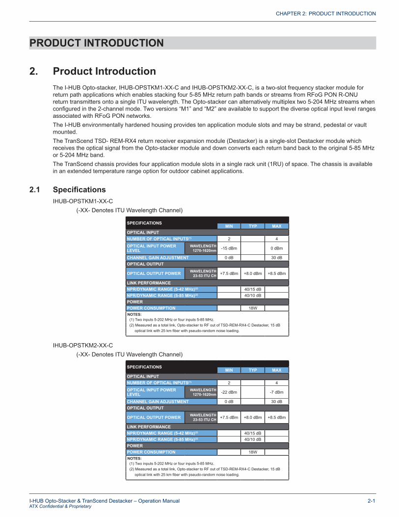
2. Product Introduction The I-HUB Opto-stacker, IHUB-OPSTKM1-XX-C and IHUB-OPSTKM2-XX-C, is a two-slot frequency stacker module for return path applications which enables stacking four 5-85 MHz return path bands or streams from RFoG PON R-ONU return transmitters onto a single ITU wavelength. The Opto-stacker can alternatively multiplex two 5-204 MHz streams when configured in the 2-channel mode. Two versions “M1” and “M2” are available to support the diverse optical input level ranges associated with RFoG PON networks. The I-HUB environmentally hardened housing provides ten application module slots and may be strand, pedestal or vault mounted. The TranScend TSD- REM-RX4 return receiver expansion module (Destacker) is a single-slot Destacker module which receives the optical signal from the Opto-stacker module and down converts each return band back to the original 5-85 MHz or 5-204 MHz band.The TranScend chassis provides four application module slots in a single rack unit (1RU) of space. The chassis is available in an extended temperature range option for outdoor cabinet applications.
2.1 Specifications IHUB-OPSTKM1-XX-C (-XX- Denotes ITU Wavelength Channel)
IHUB-OPSTKM2-XX-C (-XX- Denotes ITU Wavelength Channel)
CHAPTER 2:
SPECIFICATIONSMIN TYP MAX
OPTICAL INPUTNUMBER OF OPTICAL INPUTS(1) 2 4
OPTICAL INPUT POWER LEVEL
WAVELENGTH 1270-1620nm -15 dBm 0 dBm
CHANNEL GAIN ADJUSTMENT 0 dB 30 dBOPTICAL OUTPUT
OPTICAL OUTPUT POWER WAVELENGTH 23-53 ITU CH +7.5 dBm +8.0 dBm +8.5 dBm
LINK PERFORMANCENPR/DYNAMIC RANGE (5-42 MHz)(2) 40/15 dBNPR/DYNAMIC RANGE (5-85 MHz)(2) 40/10 dBPOWERPOWER CONSUMPTION 18W NOTES: (1) Two inputs 5-202 MHz or four inputs 5-85 MHz. (2) Measured as a total link, Opto-stacker to RF out of TSD-REM-RX4-C Destacker, 15 dB optical link with 25 km fiber with pseudo-random noise loading.
SPECIFICATIONSMIN TYP MAX
OPTICAL INPUTNUMBER OF OPTICAL INPUTS(1) 2 4
OPTICAL INPUT POWER LEVEL
WAVELENGTH 1270-1620nm -22 dBm -7 dBm
CHANNEL GAIN ADJUSTMENT 0 dB 30 dBOPTICAL OUTPUT
OPTICAL OUTPUT POWER WAVELENGTH 23-53 ITU CH +7.5 dBm +8.0 dBm +8.5 dBm
LINK PERFORMANCENPR/DYNAMIC RANGE (5-42 MHz)(2) 40/15 dBNPR/DYNAMIC RANGE (5-85 MHz)(2) 40/10 dBPOWERPOWER CONSUMPTION 18W NOTES: (1) Two inputs 5-202 MHz or four inputs 5-85 MHz. (2) Measured as a total link, Opto-stacker to RF out of TSD-REM-RX4-C Destacker, 15 dB optical link with 25 km fiber with pseudo-random noise loading.

PRODUCT INTRODUCTION
2-2 I-HUB Opto-Stacker & TranScend Destacker – Operation ManualATX Confidential & Proprietary
CHAPTER 2:
This page intentionally left blank.

DESCRIPTION OF MODULE OPERATION
I-HUB Opto-Stacker & TranScend Destacker – Operation Manual 3-1ATX Confidential & Proprietary
DESCRIPTION OF MODULE OPERATION
3. Description of Module Operation
3.1 I-HUB Opto-StackerThe I-HUB Opto-stacker module has four optical input ports. Ports one through four are utilized when the RF stream bandpass is between 5-85 MHz and ports one and three are utilized for 5-204 MHz operation. At the input of each port is an optical receiver specified to accept optical signals between 1270-1610nm with an optical level between -12 to +3 dBm (model “M”). Following each receiver is an RF attenuator which is adjusted automatically (in AGC mode) by a microcontroller to attenuate for any difference in optical input level between each input port to ensure each band is set to the same RF level before each return band is upconverted to a higher frequency band. Since RFoG R-ONUs transmit in burst mode, an optical signal is not always present at the input of the Opto-stacker thus the module should be set to MGC mode and not AGC mode.
Each RF band signal is upconverted and all upconverted bands, four 5-85 MHz or two 5-204 MHz bands, are combined. A pilot tone is injected with the return bands to provide a reference signal for the headend TranScend Destacker module to provide a constant link gain control for the recovered RF stream. The Opto-stacker also connects to the I-HUB Controller module FSK signal collecting the I-HUB configuration and status signals which is accessed at the connected TranScend chassis. The RF signal is then modulated onto an ITU optical wavelength for transmission to the TranScend Destacker module.
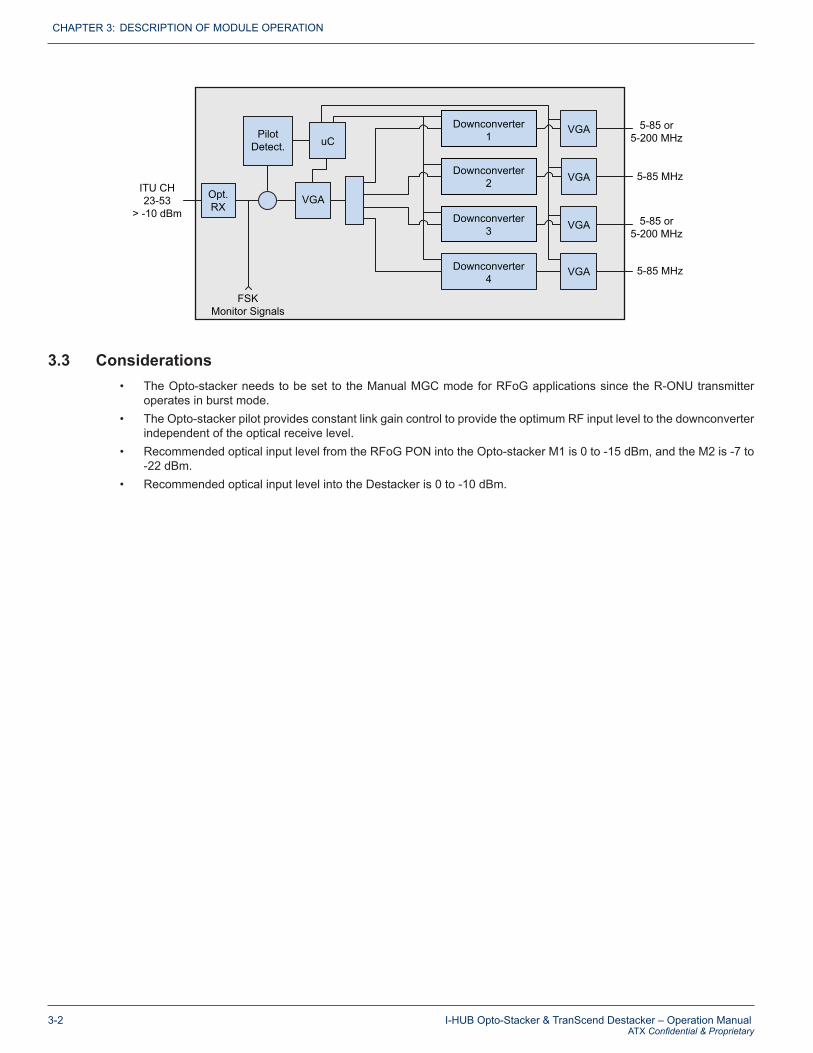
3.2 TranScend DestackerThe incoming optical signal from the Opto-stacker carries the frequency stacked return bands (four 5-85 or two 5-204 MHz) as well as a Pilot Carrier. After the optical receiver, a variable gain amplifier is controlled by the Opto-stacker Pilot Carrier providing a constant RF level independent of the optical receive level. Next are the downconverter mixers which recover the two or four return bands back to the original 5-85 or 5-204 MHz bands. Each band is amplified by the output VGAs which also allows for individual adjustment of each output RF signal.
CHAPTER 3:
1270-1620nm“M” = +3 to -12 dBm“M1” = 0 to -15 dBm“M2” = -7 to -22 dBm
Opt.RX 1
Opt.RX 2
Opt.RX 3
Opt.RX 4
5-85 or 5-200 MHz
5-85 or 5-200 MHz
5-85 MHz
5-85 MHz
RFAtten.
RFAtten.
RFAtten.
RFAtten.
Upconverter1
Upconverter2
Upconverter3
Upconverter4 uC
Pilot
ITUTX
FSKMonitor Signals
ITU CH23-53
+8 dBm
DESCRIPTION OF MODULE OPERATION
3-2 I-HUB Opto-Stacker & TranScend Destacker – Operation ManualATX Confidential & Proprietary
3.3 Considerations • The Opto-stacker needs to be set to the Manual MGC mode for RFoG applications since the R-ONU transmitter
operates in burst mode.• The Opto-stacker pilot provides constant link gain control to provide the optimum RF input level to the downconverter
independent of the optical receive level.• Recommended optical input level from the RFoG PON into the Opto-stacker M1 is 0 to -15 dBm, and the M2 is -7 to
-22 dBm.• Recommended optical input level into the Destacker is 0 to -10 dBm.
CHAPTER 3:
ITU CH23-53
> -10 dBm
Opt.RX
PilotDetect. uC
VGA
FSKMonitor Signals
Downconverter1
Downconverter2
Downconverter3
Downconverter4
VGA
VGA
VGA
VGA
5-85 or 5-200 MHz
5-85 or 5-200 MHz
5-85 MHz
5-85 MHz
LEVEL SET-UP
I-HUB Opto-Stacker & TranScend Destacker – Operation Manual 4-1ATX Confidential & Proprietary
LEVEL SET-UP
4. Level Set-up
4.1 Opto-Stacker• Insert a CW carrier at a micro node located on the PONs that are connected to each port of the Opto-stacker and set
to the recommended level. • Connect the fibers to the Opto-stacker input ports, ports one through four for 5-85 MHz or ports one and three for
5-204 MHz.
• Connect the I-HUB hand-held display unit into the I-HUB DSUB -15 connector. (Refer to ATX’s I-HUB Chassis Operation Manual for configuration utilizing the hand-held Controller)
• After selecting the desired Opto-stacker from the chassis slot which it is populated in, select the “Setup Menu”. • Choose “Sel Chnl” and select the desired channel 1 through 4.• Toggle down to the “Mode Setting Menu”. Press the “right” or “left” button to select “AGC” and press “Select”.• Toggle down to “Save” and press the “right” or “left” button to choose “Yes” and press “Select” to save your selection. • With the unit in AGC mode, note the RF Attn (dB) setting. • Return to the “Mode Setting Menu” and set the channel in MGC mode and adjust the RF Attn (dB) to the value noted
from the AGC mode.• Save the RF Attn value. • Be certain to leave the channel in the MGC mode.• Repeat the process on the remaining channels or ports.
4.2 Destacker• Connect the fiber from the Opto-stacker into the Destacker input port. (Optical level should be 0 to -10 dBm)• On the front panel of the TranScend chassis adjust Attn (dB) to desired RF output on each port of the Destacker
module. The recommended maximum output level is +40 dBmV. (Refer to Tech Note – TranScend User Interface)
CHAPTER 4:

LEVEL SET-UP
4-2 I-HUB Opto-Stacker & TranScend Destacker – Operation ManualATX Confidential & Proprietary
This page intentionally left blank.
CHAPTER 4:
SERVICE & SUPPORT
I-HUB Opto-Stacker & TranScend Destacker – Operation Manual 5-1ATX Confidential & Proprietary
SERVICE & SUPPORT
5. Service & Support
5.1 Contact ATX NetworksPlease contact ATX Technical Support for assistance with any ATX products.
TECHNICAL SUPPORTTel: 289.204.7800 – press 1Toll-Free: 866.YOUR.ATX (866.968.7289) USA & Canada onlyEmail: [email protected]
SALES ASSISTANCETel: 289.204.7800 – press 2Toll-Free: 866.YOUR.ATX (866.968.7289) USA & Canada onlyEmail: [email protected]
FOR HELP WITH AN EXISTING ORDERTel: 289.204.7800 – press 3Toll-Free: 866.YOUR.ATX (866.968.7289) USA & Canada onlyEmail: [email protected]: www.atx.com
5.2 Warranty InformationAll of ATX Networks’ products have a 1-year warranty that covers manufacturer’s defects or failures.
CHAPTER 5:

ISO9001:15
REGISTERED
www.atx.com
Rev. 02/20 (ANW1204)
ATX NetworksTel: 289.204.7800 | Toll-Free: 866.YOUR.ATX (866.968.7289) | [email protected]
© 2020 by ATX Networks Corp. and its affiliates (collectively “ATX Networks Corp.”). All rights reserved. This material may not be published, broadcast, rewritten, or redistributed. Information in this document is subject to change without notice.