Embed Size (px)
Citation preview

T67STEERING SYSTEM
Installation and maintenance manual
ULTRAFLEXPARTNER
RIT
AL
IAN
O
(Dr./Dis./Des. n° 12884/c 06/05/2015)
FR
AN
ÇA
ISE
NG
LIS
H

Dear Customer,
We would like to thank you for choosing an ULTR AFLEX product.
ULTRAFLEX has been a leader in steering systems for pleasure and professional boats for many years.ULTR AFLEX production is since ever synonimous of reliability and safety.
All ULTR AFLEX products are designed and manufactured to ensure the best performance.To ensure your safety and to maintain a high quality level, ULTR AFLEX products are guaranteed only ifthey are used with original spare parts.
ULTRAFLEX and UFLEX Quality Management Systems are certified CISQ-IQNet by the Italian ShippingRegistry (RINA), in conformity with the UNI EN ISO 9001:2008 rule. ULTRAFLEX certification No. 6669/02/S(former 420/96). UFLEX certification No. 8875/03/S.
The quality management system involves all the company resources and processes starting from thedesign, in order to:- ensure product quality to the customer;- maintain and improve the quality standards constantly;- pursue a continuous process improvement to meet the market needs and to increase the customer
satisfaction
ULTRAFLEX Environmental Management System is certified CISQ-IQNet by the Italian Shipping Registry(RINA), in conformity with the UNI EN ISO 14001 rule. ULTRAFLEX certification No. EMS-1282/S.
Products for pleasure boats are constantly tested to check their conformity with the 2013/53/EU.
ULTRAFLEX S.p.A.
ULTRAFLEX
16015 Casella (Genova) Italia - Via Crose, 2
"ULTRAFLEX has over 80 years of experience in the marine industry and is a world leader in the productionof mechanical, hydraulic and electronic steering systems, control boxes and steering wheels for anykind of pleasure, fishing or commercial boats.The key factors which explain the increasing success of our products all over the world are the reliabilityof our products and the before and after sale service, the quality of the company organization and of thehuman resources and the continuous spending in research and development".
EN
GL
ISH

T67 STEERING SYSTEM - page 3 of 43
Installation and maintenance manualULTRAFLEX
EN
GL
ISH
SECTION 1 - PRODUCT DESCRIPTION1.1 DESCRIPTION OF THE PRODUCT AND WARNINGS FOR THE CORRECT USE................................................61.2 DIMENSIONS..................................................................................................................................6
TABLE OF CONTENTS
SECTION 2 - TRANSPORT2.1 GENERAL WARNINGS.............................................................................................................................82.2 PACKAGING CONTENTS...........................................................................................................................8
SECTION 5 - MAINTENANCE5.1 ROUTINE MAINTENANCE.................................................................................................................145.2 EXTRAORDINARY MAINTENANCE.....................................................................................................14
SECTION 3 - INSTALLATION3.1 NECESSARY TOOLS.................................................................................................................................93.2 HELM POSITIONING..................................................................................................................93,3 CONNECTION OF THE SINGLE CABLE TO THE HELM...............................................................................11
SECTION 4 - SAFETY WARNINGS4.1 SAFETY RULES DURING INSTALLATION AND USE.. ... .......................................................134.2 CLOTHING.....................................................................................................................................13
SECTION 6 - DISMANTLING6.1 DISMANTLING..........................................................................................................................14
!
MANUAL USE AND SYMBOLS USED................................................................................................................4INTRODUCTION......................................................................................................................................5WARRANTY... .. .. .. .. ... .. .. .. ... .. .. .. ... .. .. .. .. ... .. .. .. ... .. .. .. ... .. .. .. .. ... .. .. .. ... .. .. .. .. ... .. .. .. ... .. .. .. ... .. .. .. .. ... .. .. .. .5

Installation and maintenance manualULTRAFLEX
page 4 of 43 - T67 STEERING SYSTEM
EN
GL
ISH
In this manual the following symbols are used to ensure the user safety and to guarantee the correctoperation of the product:
MANUAL USE AND SYMBOLS USEDTHE INSTALLATION AND MAINTENANCE MANUAL is the document given with the product from its sale to itsreplacement and discharge. The manual is an important part of the product itself.It is necessary to read carefully the manual, before ANY ACTIVITY involving the product, handling andunloading included.
STERN
BOW
STARBOARD PORTThe symbols aside indicate all the operationswhich must be carried out by qualified or skilledstaff, in order to avoid hazards.
DANGER Immediate hazards which CAUSE severe personal injury or death.
WARNING
CAUTION
The symbol aside indicates all the operations which must be carried outby qualified or skilled staff, in order to avoid hazards.We recommend training the staff in charge of the product installationand checking their knowledge.
NOTICE Important information for the correct installation and for maintenance, thatdoes not cause any damage.
Denotes that a hazard exists which can result in injury or death if properprecautions are not taken.
Denotes a reminder of safety practices or directs attention to unsafepractices which could result in personal injury or damage to the craft orcomponents or to the environment.

T67 STEERING SYSTEM - page 5 of 43
Installation and maintenance manualULTRAFLEX
EN
GL
ISH
WARRANTY
TECHNICAL ASSISTANCE SERVICE
INTRODUCTION
UFLEX S.r.l.Via Milite Ignoto,8A16012 Busalla (GE)-ItalyPh: +39.010.962.0239 (Italy)Ph: +39.010.962.0244 (Abroad)Fax: +39.010.962.0333Email: [email protected]
North - South - Central America:U F LE X USA6442 Parkland DriveSarasota, FL 34243Ph: +1.941.351.2628Fax: +1.941.360.9171Email: [email protected]
This installation and maintenance manual represents an important part of the product and must be availableto the people in charge of its use and maintenance.The user must know the content of this manual.ULTRAFLEX declines all responsibility for possible mistakes in this manual due to printing errors.Apart from the essential features of the described product, ULTRAFLEX reserves the right to make thosemodifications, such as descriptions, details and illustrations, that are considered to be suitable for itsimprovement, or for design or sales requirements, at any moment and without being obliged to update thispublication.ALL RIGHTS ARE RESERVED. Publishing rights, trademarks, part numbers and pictures of ULTRAFLEX productsincluded in this manual are ULTRAFLEX property.Great care has been taken in collecting and checking the documentation contained in this manual tomake it as complete and comprehensible as possible. Nothing contained in this manual can be interpretedas warranty either expressed or implied - including, not in a restricted way, the suitability warranty for anyspecial purpose. Nothing contained in this manual can be interpreted as a modification or confirmation ofthe terms of any purchase contract.
To ensure the correct product and component operation, the product must be installed by qualified staff.In case of part damage or malfunction, please contact the qualified staff or our Technical AssistanceService.
WARNING
ULTRAFLEX guarantees that its products are well designed and free from manufacturing and material defects,for a period of two years from the date of manufacturing.For the products which are installed and used on working or commercial boats the warranty is limited toone year from the date of manufacturing.If during this period the product proves to be defective due to improper materials and/or manufacture, themanufacturer will repair or replace the defective parts free of charge.Direct or indirect damage is not covered by this warranty. In particular the company is not responsible and thiswarranty will not cover the damage resulting from incorrect installation or use of the product (except forreplacement or repair of defective parts according to the conditions and terms above).This warranty does not cover the products installed on race boats or boats used in competitions.The descriptions and illustrations contained in this manual should be used as general reference only.For any further information please contact our Technical Assistance Service.ULTRAFLEX steering system components are marked according to the Directive 2013/53/EU.We remind you that only marked steering systems must be used on the boats marked .
Installation and maintenance manualULTRAFLEX
page 6 of 43 - T67 STEERING SYSTEM
EN
GL
ISH
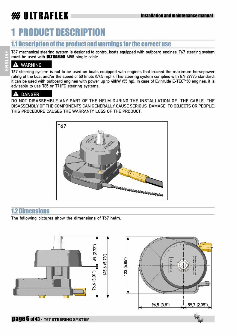
1.2 Dimensions
1 PRODUCT DESCRIPTION1.1 Description of the product and warnings for the correct useT67 mechanical steering system is designed to control boats equipped with outboard engines. T67 steering systemmust be used with ULTRAFLEX M58 single cable.
T67 steering system is not to be used on boats equipped with engines that exceed the maximum horsepowerrating of the boat and/or the speed of 50 knots (57.5 mph). This steering system complies with EN 29775 standard:it can be used with outboard engines with power up to 40kW (55 hp). In case of Evinrude E-TECTM50 engines. it isadvisable to use T85 or T71FC steering systems.
DO NOT DISASSEMBLE ANY PART OF THE HELM DURING THE INSTALLATION OF THE CABLE. THEDISASSEMBLY OF THE COMPONENTS CAN GENERALLY CAUSE SERIOUS DAMAGE TO OBJECTS OR PEOPLE.THIS PROCEDURE CAUSES THE WARRANTY LOSS OF THE PRODUCT.
The following pictures show the dimensions of T67 helm.
WARNING
DANGER
145,
6 (5
.73"
)
76,6
(3.
01")
69 (2
.72"
)
123
(4.8
5")
96,5 (3.8") 59,7 (2.35")
T67

T67 STEERING SYSTEM - page 7 of 43
Installation and maintenance manualULTRAFLEX
EN
GL
ISH
The following pictures show the required minimum dimensions for the assembly of T67 helm with M58single cable.

Installation and maintenance manualULTRAFLEX
page 8 of 43 - T67 STEERING SYSTEM
EN
GL
ISH
The packaging must be disposed of according to the existing laws.
2.1 General warnings2 TRANSPORTThe product weight with its packaging is 2.5 kg (5.5 pounds); therefore, it can be manually handled.
2.2 Packaging contentsBefore using the equipment check that the product has not been damaged during transport or storage.Also make sure that all the standard components are in the packaging (see list). In case of damage, notifythe claim to the forwarder and inform the supplier.
WARNINGThe staff in charge of handling must wear protective gloves and safety shoes.
CAUTION
Contents of the helm packagings:
CT67
A
B
H
ED
F
G
I
L
REF T67A 1 helmB 1 bracketC 1 mounting bezelD 4 washers 6.5x12E 8 nuts M6F 4 screws M6x35G 1 screw M10x50H 2 self-threading screwsI 1 washerL 1 ring
T67 STEERING SYSTEM - page 9 of 43
Installation and maintenance manualULTRAFLEX
EN
GL
ISH
3 INSTALLATION3.1 Necessary tools
Phillipsscrewdriver
2 Open endwrenches
10mm [0,395”]
Drill
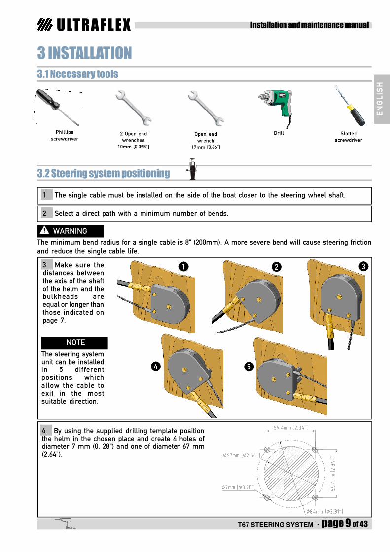
3.2 Steering system positioning
1 The single cable must be installed on the side of the boat closer to the steering wheel shaft.
2 Select a direct path with a minimum number of bends.
The minimum bend radius for a single cable is 8" (200mm). A more severe bend will cause steering frictionand reduce the single cable life.
WARNING
Open endwrench
17mm [0,66”]
Slottedscrewdriver
4 By using the supplied drilling template positionthe helm in the chosen place and create 4 holes ofdiameter 7 mm (0, 28") and one of diameter 67 mm(2,64").
3 Make sure thedistances betweenthe axis of the shaftof the helm and thebulkheads areequal or longer thanthose indicated onpage 7.
The steering systemunit can be installedin 5 differentpositions whichallow the cable toexit in the mostsuitable direction.
NOTE
1 2 3
4 5

Installation and maintenance manualULTRAFLEX
page 10 of 43 - T67 STEERING SYSTEM
EN
GL
ISH
5 Tighten the bracket (1) to the dashboard usingfour screws M6x35 (hexagonal head) (2), fourwashers (3) and four self stopping nuts M6 (4) withtorque of 6 Nm (53 lbs in).
6 Insert the helm shaft from the back side ofthe dashboard through the hole of the mountingbracket. The helm can be fixed in 5 differentpositions (every 45°).The right position will bedetermined by the mounting side of the singlecable. Place the helm in the selected positionand align the holes for mounting. Tighten the helmto the bracket with four M6 self-locking nuts (5)with torque of 6 Nm (53 lbs in).
1
2
3
4
5
7 Insert the ring (6) on the helm bezelconsidering that the adjusting screw (7) must bealigned with the mounting bezel hole (8).
8 Insert the mounting bezel (8) and bringing incontact with the dashboard (9).Fix the mounting bezel (8) to the dashboard (9)by means of two self-threading screws (10).
FRICTION ADJUSTMENTHOLE POSITION
6
7
8
10
9

T67 STEERING SYSTEM - page 11 of 43
Installation and maintenance manualULTRAFLEX
EN
GL
ISH
3.3 Single cable connection to the steering system
1 Determine the correct entry position of the single cable into the helm according to the propersteering system.
2 Remove protective tube (16) from cableULTRAFLEX M58 but preserve it (see picture 4) andkeep it clean. Insert the helical cable into thehelm.
3 Turn the steering wheel so as to pull thecable into the helm, making the cable sheath end(17) touch the nut (18).
PUSH OR PULL TURNING DIRECTIONS
17
9 Insert the steering wheel (11) on the helmshaft (12) aligning the recess of the hub with thekey (13) of the shaft.Insert the washer (14) and screw the M10 screw(15) on the hub of the steering wheel, with torqueof 35-40Nm (310-354 lbs in).
13
11
14
15
12
Do not use a steering wheel with diameter wider than 380 mm (15").
WARNING
18
16

Installation and maintenance manualULTRAFLEX
page 12 of 43 - T67 STEERING SYSTEM
EN
GL
ISH
4 Turn the helm nut (18) to screw the cablesheath end (17) until it touches it. Then insert theprotective tube (16) removed before (see pic. 2)and place it on the cable coming from the helmuntil the the helm tube is covered.
6 Make sure the direction of the steering wheel rotation corresponds to the boat direction.
This control must be carried out before the boat is operated in the water.
WARNING
1817
5 Fix the cable sheath every 2 m (6'). The sheathmust not be fixed to the electric wires.Bulkhead openings require a minimum 38mm(1 1/2) hole diameter.
Make sure the single cable sheath does not enter in contact with cutting edges that could damage it.
DANGER
DANGER
During the single cable assembly on the helm, prevent any dust orforeign material from coming in contact with cable end and the helmitself.
7 To modify the sensitivity of the steering wheelit is possible to adjust the friction positioned onthe hub. By means of a slotted screwdriver (X),act on the screw (7) through the mounting bezelhole.
X
7
16
2m2m

T67 STEERING SYSTEM - page 13 of 43
Installation and maintenance manualULTRAFLEX
EN
GL
ISH
4 SAFETY WARNINGSThis section shows the safety rules which must be followed for the correct equipment operation.We recommend reading carefully this section and also the other manuals supplied with the steering systemcomponents.
4.1 Safety rules during installation and useOBSERVE STRICTLY the following safety rules:ULTRAFLEX declines all responsibility in case the user does not follow these rules and it is not responsible fornegligence while using the system.
- DO NOT PUT YOUR HANDS BETWEEN MOVING PARTS.- Do not disable the safety devices.- Do not modify or add devices to the system, without ULTRAFLEX written authorisation or technical
intervention which will prove the modification in the report.- Do not use this equipment for a purpose different from the one it has been designed for, which is
specified in the installation and maintenance manual.- Do not let unskilled staff perform the installation.
DANGER
WARNING- During installation, keep the system clean, to prevent any foreign body to damage it. Even the smallest
object could cause permanent but not immediately perceivable damages.- Avoid cable bends 200 mm (8")- Avoid contact of cables with sharpened edges- Avoid contact with sources of heat.
During installation, inspection or maintenance,IT IS STRICTLY FORBIDDEN to wear necklaces, bracelets or clothes which could get caught in the movingparts.
4.2 ClothingWARNING

Installation and maintenance manualULTRAFLEX
page 14 of 43 - T67 STEERING SYSTEM
EN
GL
ISH
5.1 Ordinary maintenance5 MAINTENANCE
Poor installation and maintenance may result in loss of steering and cause property damage and/or perso-nal injury. Maintenance requirements change according to climate, frequency and the use. Inspections arenecessary at least every year and must be carried out by specialized marine technicians.Carry out the following maintenance operations:- Periodically wash with water and soap the single cable removing any salt deposit.- Every month check and if necessary tighten all the nuts fastening the system.
WARNING
DANGERRelease or separation of one of the fasteners can cause failure of steering system resultingin property damage, injury or death.- Periodically check the absence of corrosion on the metal parts of the cable end fittings and of abrasions
on the conduit.- Replace the damage parts that could compromise the steering system integrity.
Technical Support
For any information or for assistance with unusual applications please contact our technical support staff(See paragraph "Introduction").
5.2 Extraordinary maintenance
6 DISMANTLING6.1 DismantlingWhen for any reason, the system is put out of service, it is necessary to follow some rules in order torespect the environment.Conduits, pipelines, plastic or non-metallic components must be disassembled and disposed of separately.


![Danz6n No - Berkner Orchestra...£ F ~r I f £ f Cfl r-Nr I F ~ - 1 1 - I I f JJ . .I-z.__ 2 Danzon No 2 (R. 04-01) Contrabajos (Double Bass) 011] . plZZ ~= F t F F I E. F. E I F t](https://img.dokumen.tips/doc/110x75/60d9dd9b0d1d481c7d34cad6/danz6n-no-berkner-orchestra-f-r-i-f-f-cfl-r-nr-i-f-1-1-i-i-f.jpg)