Embed Size (px)
Citation preview
I ;I"
Vapor Emission Control In Vapor Degreasing and Defluxing Equipment
Robert B. Ramsey, Jr. Senior Technical Service Consultant E. I. Du Pont De Nemours and Company
INTRODUCTION
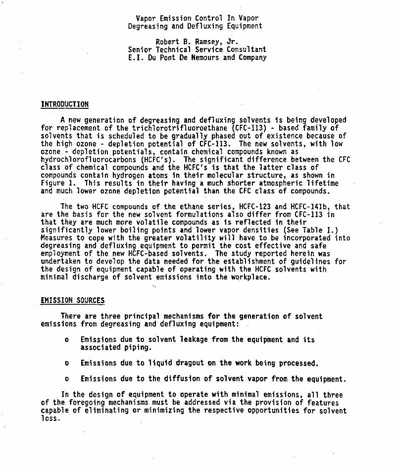
A new generation of degreasing and defluxing solvents is being developed for replacement of the trichlorotrifluoroethane (CFC-113) - based family of solvents that is scheduled to be gradually phased out of existence because of the high ozone - depletion potential of CFC-113. The new solvents, with low ozone - depl et ion potenti a1 s, contain chemi cal compounds known as hydrochlorofluorocarbons (HCFC's). The significant difference between the CFC class o f chemical compounds and the HCFC's i s that the latter class of compounds contain hydrogen atoms in their molecular structure, as shown in Figure 1. This results in their having a much shorter atmospheric lifetime and much lower ozone depletion potential than the CFC class of compounds.
are the basis for the new solvent formulations also differ from CFC-113 in that they are much more volatile compounds as is reflected in their significantly lower boiling points and lower vapor densities (See Table I.) Measures to cope with the greater volatility will have to be incorporated into degreasing and defluxing equipment to permit the cost effective and safe employment of the new HCFC-based solvents. The study reported herein was undertaken to develop the data needed for the establishment o f guidelines for the design of equipment capable of operating with the HCFC solvents with minimal discharge of solvent emissions into the workplace.
The two HCFC compounds o f the ethane series, HCFC-123 and HCFC-l4lb, that
EMISSION SOURCES
There are three principal mechanisms for the generation o f solvent emissions from degreasing and defluxing equipment:
o Emissions due to solvent leakage from the equipment and its associated piping.
Emissions due to liquid dragout on the work being processed.
Emissions due to the diffusion of solvent vapor from the equipment.
In the design of equipment to operate with minimal emissions, all three
o
o
of the foregoing mechanisms must be addressed via the provision of features capable of eliminating or minimizing the respective opportunities for solvent 1 oss.

' i ' .
CONTROL OF EMISSIONS DUE TO LEAKAGE
b u i l d i n g the cleaning u n i t , and of the at tent ion pa id t o i t s subsequent maintenance. However, there are some design parameters t h a t need t o be considered t o minimize leakage losses:
w i t h the employed solvent. is avai lable from the solvent suppliers (Refs. 1, 2 and 3).
from materials t h a t a r e chemically compatible w i t h t he employed solvent. Type 304 and Type 316 s t a in l e s s s t e e l s are the preferred materials of construction f o r t he fabricat ion of degreasers and defluxers f o r employment w i t h the HCFC solvents. Copper and brass may be acceptable materials f o r valves and p ip ing i n degreasers i f they a re compatible w i t h the metal working soils being removed from the work. They should n o t be used f o r process piping i n defluxing equipment, since the copper may dissolve and redeposit across c i r c u i t s .
Leakage losses a re primarily a ref lect ion of the workmanship p u t i n t o
o Seals and Gaskets - Seals and gaskets must be chemically compatible Information on this subject has been developed and
o Materials of Construction - The equipment a lso should be fabricated
o Pipinq - Past experience has shown t h a t i t is d i f f i c u l t t o obtain good leak - f r e e joints i n threaded s ta in less s t ee l p ip ing . Welded o r soldered j o i n t p ip ing , w i t h flanged connections f o r removal of accessories (pumps, f i l t e r s , dryers, etc.) is the recommended construction t o minimize leakage problems i n equipment employing the HCfC solvents.
CONTROL OF EMISSIONS DUE TO ORAGOUT
Solvent dragout is , i n large p a r t , a function o f the geometry of the p a r t being cleaned, but i t a l so can be, i n large par t , a ref lect ion of the care, or lack of care, taken i n handling and conveying the work item through the cl ean i ng process.
Dragout can be minimized by paying careful a t tent ion t o the design of work baskets and work fixtures and t o methods of racking or orienting the work f o r cleaning t o provide f o r minimum entrapment and maximum drainage of solvent during the cleaning process. Baskets processing a random f i l l of a mu1 t i p 1 i c i t y of par t s having cupping charac te r i s t ics should be rotated dur ing cleaning t o f a c i l i t a t e l i q u i d drainage.
The movement of t he workload through the degreaser o r defluxer should be carefu l ly controlled t o avoid excessive disturbance o f the vapor/air interface during work inser t ion and withdrawal. Adequate residence time a l so i s needed 5n t he vapor zone a f t e r cleaning t o obtain good l i q u i d drainage and temperature equi l ibrat ion of the work w i t h the solvent vapor. The recommended maximum speed f o r work entry and removal from degreasers and defluxers is 10 ~ m ( R e f s . 4 and 5)
from the use of programmable work t ransporters t o convey work through top- entry type degreasers and defluxers. The attainment of the minimal levels of
Past work (Refs. 6 and 7 ) has demonstrated the benefits t o be derived
. .
emissions needed for cost e f fec t ive and safe operation of equipment con ta in ing the HCFC solvents w i l l require t h a t programmable work t ransporters be an integral component of top entry machines.
I t i s t o be noted t h a t following temperature equi l ibra t ion w i t h the vapor, and w i t h t he cessation of v i s ib l e condensation, t he work being processed is s t i l l wet w i t h a film of l i q u i d . A t this equilibrium condition, solvent evaporation from the work and solvent condensation on the work a re occurring a t equivalent ra tes . When the work is withdrawn from the degreaser o r defluxer, this film of l i q u i d evaporates and the resu l t ing vapor is emitted t o t h e atmosphere.
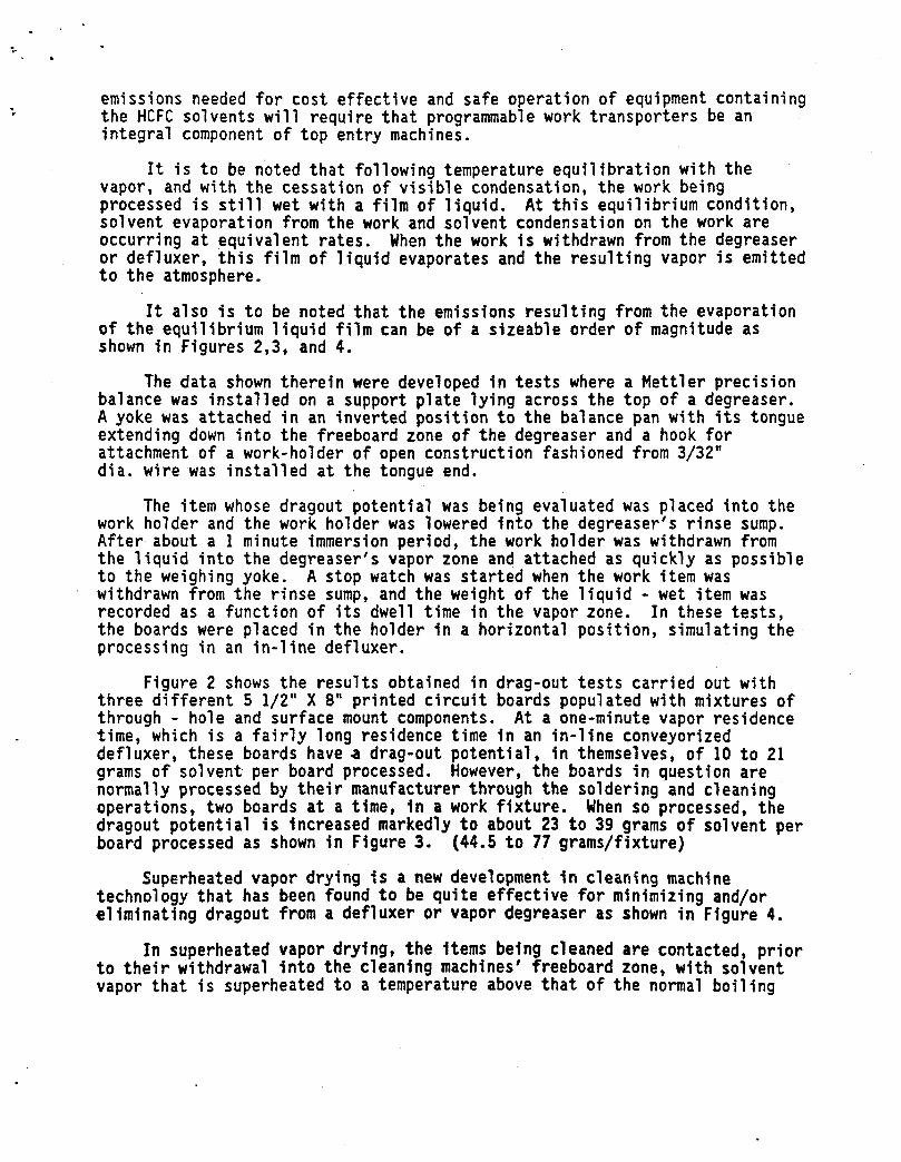
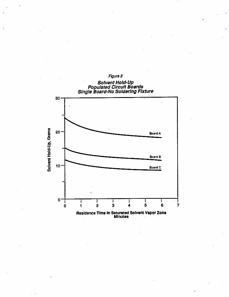
I t a l so i s t o be noted t h a t the emissions resu l t ing from the evaporation o f t h e equilibrium l i q u i d film can be of a s izeable order of magnitude as shown i n Figures 2,3, and 4.
The data shown there in were developed i n tests where a Mettler precision balance was in s t a l l ed on a support p l a t e lying across the top of a degreaser. A yoke was attached i n an inverted posit ion t o the balance pan w i t h i t s tongue extending down i n t o the freeboard zone of t he degreaser and a hook f o r attachment of a work-holder of open construction fashioned from 3/32" d i a . wire was in s t a l l ed a t the tongue end.
The item whose dragout potential was being evaluated was placed in to the work ho lde r and the work holder was lowered in to the degreaser's r i n se sump. After about a 1 minute immersion period, the work holder was withdrawn from the l i q u i d i n t o the degreaser's vapor zone and attached as quickly as possible t o the weighing yoke. withdrawn from the r in se sump, and the weight of the l i q u i d - wet item was recorded as a function of i t s dwell time i n t he vapor zone. t he boards were placed i n the holder i n a horizontal posit ion, simulating the processing i n an in-line defluxer.
A s top watch was s t a r t ed when the work item was
In these tests,
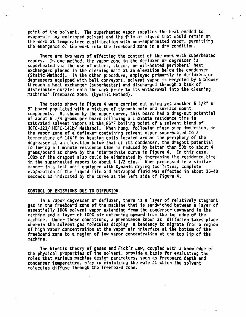
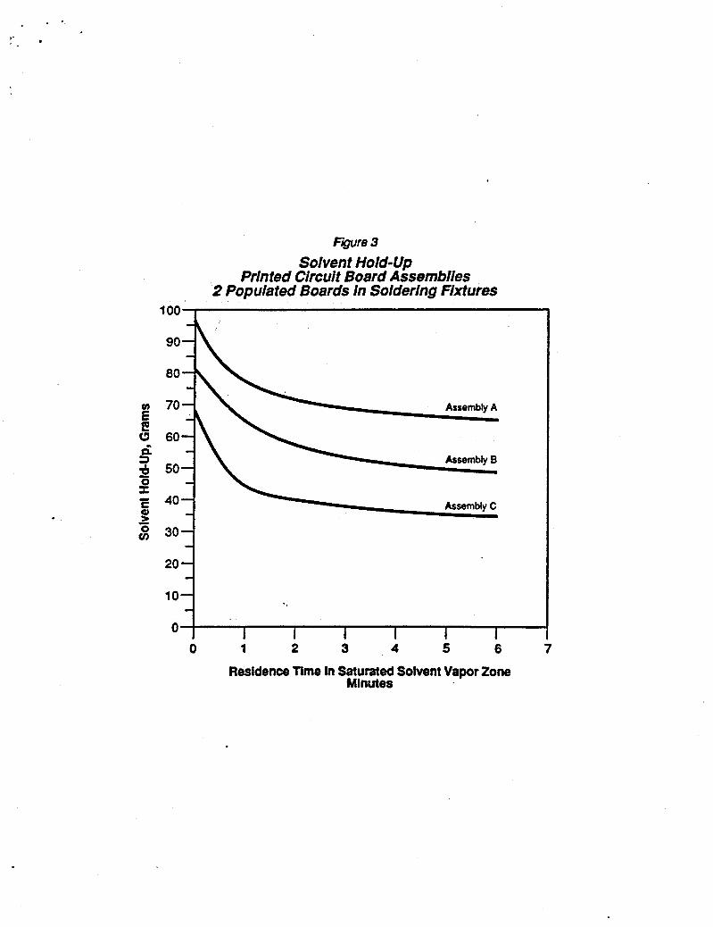
Figure 2 shows the r e s u l t s obtained i n drag-out t e s t s carr ied out w i t h th ree d i f f e ren t 5 1/2" X 8" printed c i r c u i t boards populated w i t h mixtures of through - hole and surface mount components. A t a one-minute vapor residence time, which is a f a i r l y long residence time i n an in- l ine conveyorized defluxer, these boards have a drag-out po ten t ia l , i n themselves, of 10 t o 21 grams o f solvent per board processed. However, the boards i n question a re normally processed by their manufacturer through the soldering and cleaning operations, two boards a t a time, i n a work f ix ture . When so processed, the dragout potent ia l is increased markedly t o about 23 t o 39 grams of solvent per board processed a s shown i n Figure 3. (44.5 t o 77 grams/fixture)
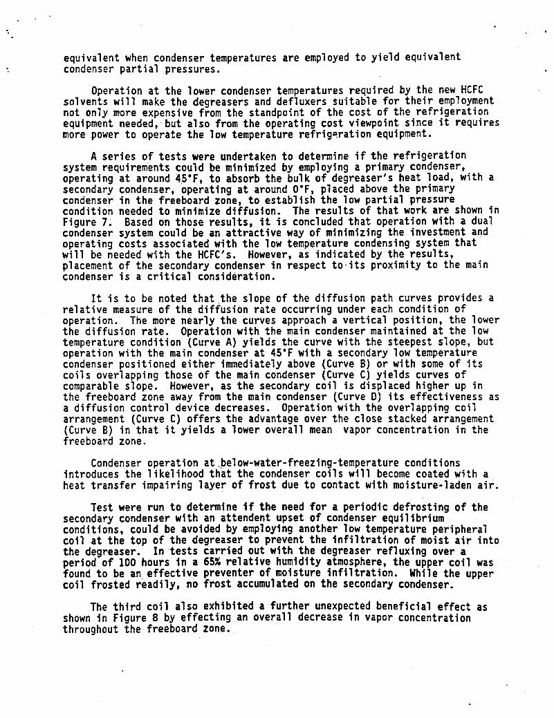
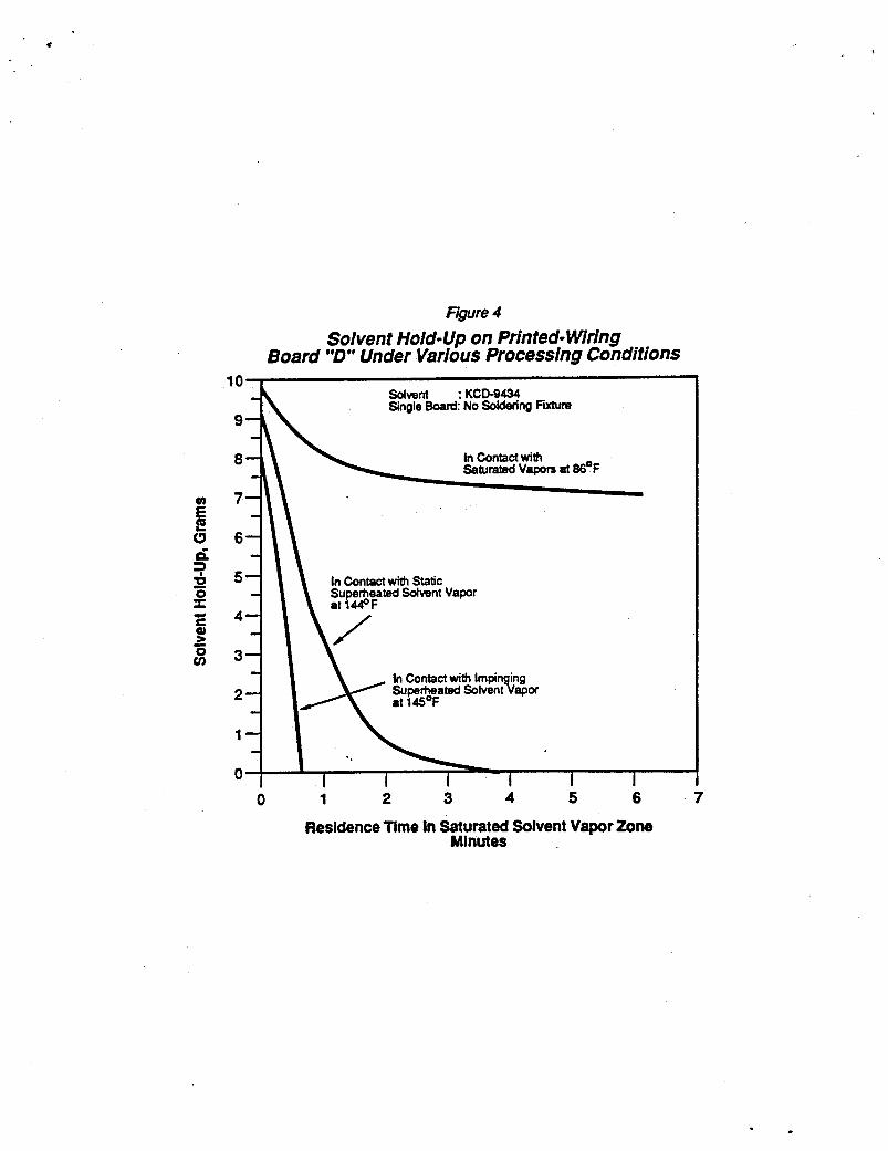
Superheated vapor drying i s a new development i n cleaning machine technology t h a t has been found t o be qui te e f fec t ive f o r minimizing and/or e l iminat ing dragout from a defluxer or vapor degreaser as shown i n Figure 4.
In superheated vapor drying, the items being cleaned a re contacted, p r io r t o t h e i r withdrawal i n t o the cleaning machines' freeboard zone, w i t h solvent vapor t h a t i s superheated t o a temperature above t h a t o f the normal b o i l i n g
p o i n t of the solvent. evaporate any entrapped solvent and the film of l i q u i d t h a t would remain on the work a t temperature equi l ibrat ion w i t h non-superheated vapor, permitting the emergence o f the work in to the freeboard zone i n a dry condition.
vapors. superheated v ia the use o f water-, steam-, o r oil-heated peripheral heat exchangers placed i n the cleaning u n i t a t an elevation below the condenser ( S t a t i c Method). degreasers equipped w i t h be l t conveyors, solvent vapor is recycled by a blower through a heat exchanger (superheater) and discharged through a bank of d i s t r i b u t o r nozzles onto the work pr ior t o i t s withdrawal i n t o the cleaning machines' freeboard zone. (Dynamic Method).
The t e s t s shown i n Figure 4 were carr ied out using yet another 5 112" x 8" board populated w i t h a mixture of through-hole and surface mount components. As shown by the upper curve, this board had a drag-out potential of about 8 1/4 grams per board following a 1 minute residence time i n saturated solvent vapors a t the 86'F boiling point of a solvent blend o f HCFC-123/ HCFC-l4lb/ Methanol. When hung, following r in se sump immersion, i n the vapor zone of a defluxer containing solvent vapor superheated t o a temperature o f 144'F by heating c o i l s located around the periphery of the degreaser a t an elevation below t ha t of its condenser, the dragout potential following a 1 minute residence time is reduced by be t t e r than 50% t o about 4 grams/board a s shown by the intermediate curve i n Figure 4 . In this case, 100% of the dragout a l so could be eliminated by increasing the residence time i n t he superheated vapors t o about 4 1/2 mins. When processed i n a s imilar manner i n a t e s t u n i t equipped w i t h Dynamic drying f a c i l i t i e s , complete evaporation of t he 1iquid.f i lm and entrapped f l u i d was effected i n about 35-40 seconds a s indicated by the curve a t the l e f t s ide of Figure 4.
The superheated vapor supplies the heat needed t o
There a r e two ways of effecting the contact of the work w i t h superheated In one method, the vapor zone i n the defluxer o r degreaser is
In the other procedure, employed primarily i n defluxers o r
CONTROL OF EMISSIONS DUE TO DIFFUSION
In a vapor degreaser o r defluxer, there is a l aye r of r e l a t ive ly stagnant gas i n t he freeboard zone o f the machine t h a t is sandwiched between a layer of e s sen t i a l ly 100% solvent vapor extending from the condenser downward i n the machine and a layer of 100% a i r extending upward from the top edge o f the machine. Under these conditions, a phenomenon known as diffusion takes place wherein the solvent gas molecules display a tendency t o migrate from a region of high vapor concentration a t the vapor a i r in te r face a t the bottom of the freeboard zone t o a region o f low vapor concentration a t the top l i p of the machi ne.
The kinetlc theory of gases and Fick's law, coupled w i t h a knowledge of the physlcal propert ies o f the solvent, provide a basis f o r evaluating the ro l e s t h a t various machine design parameters, such a s freeboard depth and condenser temperature, play i n minimizing the r a t e a t which the solvent molecules diffuse through the freeboard zone.

.. In the case of vapor degreasing equipment, the system geometry and the confined nature of the stagnant gas layer permit the use of a one dimensional diffusional equation. The rate of diffusion (N) in the vertical direction then is proportional to the diffusion coefficient or diffusivity (Dg) of the vapor/air mixtures being evaluated mu1 tip1 ied by the vapor concentration gradient (u) along the diffusion path divided by the length of the diffusion
path (L) or DG ("c) (Equation 1) A L
N{ .(al)- L
The diffusion coefficient (Dg) i s a function of the molecular properties of air and the diffusing gas and it can be predicted accurately (Ref. 8) by the following Wilke and Lee modification (Ref. 9) of the Hirschfelder, Bird and Spotz equation (Ref. 10):
(Equation 2)
where: T = absolute temperature, 'K M i = molecular w t of diffusing gas Me = molecular wt of air = 28.966 (Ref.11)
P = absolute pressure, atm. r = collision diameter, angstroms Id = collision integral for diffusion
- 1 + 1 ) x 10 -4 (Equation 3) M1 M2
and B = (10.7-2.46
A comparison of the calc<ulated diffusivities of the new HCFC compounds with that of CFC - 113 i s shown in Table SI. The diffusivities of the HCFC compounds are of the order of 9 to 16% greater than that of CFC-113. Therefore, unless some corrective action is taken to cope with the higher diffusitivity, one could expect to encounter diffusional losses in the operation of degreasers employing the HCFC's that would be signficantly higher than those of a similar unit employing CFC-113. However, by reference back to Equation 1, it is apparent that the increased diffusivity of the HCFC's can be offset by a compensating increase in the length of diffusion path; i.e, the freeboard depth o f the degreaser.
The effects associated with the concentration gradient term in Equation 1 can be evaluated by use of an Integrated form of the equation which yields the fol 1 owing re1 at i onshi p :

. -
(Equation 4)
where: XFO - Concentration of diffusing gas at
the start of the diffusion path, mol fraction.
XFL - Concentration of diffusing gas at the end o f t h e diffusion path, mol fraction
The atmosphere at the top plane o f the degreaser will contain a few parts per million of,solvent vapor, but for all practical considerations XFL can be assumed, in the analysis of diffusion loss, to be essentially equal to zero. The concentration of the diffusing gas at the start of the diffusion path, XFO, is dependent upon the condenser temperature and, by Daltons Law, can be shown to be equal to Po/Pt where:
Po - Vapor pressure o f the diffusing gas at the condenser temperature and
Pt = total pressure, which in case o f a degreaser or defluxer = 14.696 PSIA (1 atm)
With the substitution of the foregoing values into Equation 4:
(Equation 5)
Equation 5 indicates that operation with different solvents can be carried out at equivalent concentration gradients by selecting condenser tenperatures that yield the same partial pressure at the start of the diffusion path. Therefore, Equation 5 can be used to establish the maximum condenser temperature that can be employed with the HCFC solvents to maintain a driving force potential for diffusion that is no greater than that now encountered with CFC-113. The results of an analysis of this nature are shown in Table I11 where are listed the condenser temperatures needed with the candidate HCFC solvents to yield the same partial pressure of 3.02 PSIA that i s encountered with CFC-113 at a condenser temperature of 45.F.
Based on Equation 1 and the foregoing analysis of its elements, it can be seen that, to control the diffusional emissions, degreasers or defluxers which employ the new solvents containing HCFC-123 and HCFC-141b will need to be

equipped w i t h deeper freeboards and have provisions for operation a t subs tan t ia l ly lower condenser temperatures than a re now employed i n equipment f o r use w i t h CFC-113.
Following the theoret ical analysis of factors involved i n the control o f diffusional emissions, an experimental program was i n i t i a t e d t o va l ida te t h e theoret ical conclusions. This work was carr ied out us ing a 12' wide x 36" long, tuo-sump, open-top vapor degreaser. concentration p r o f i l e i n the freeboard zone was determined under various conditions o f condenser operation and freeboard depth v i a gas samples taken by means of evacuated cy1 inders equipped w i t h cap i l la ry sampling tubes. The sampling tubes were positioned a t various elevations throughout the freeboard zone from about the bottom plane of the condenser co i l t o the top edge of t he degreaser. These samples were analyzed by gas chromatography f o r the i r a i r -solvent vapor content, and the results were compared w i t h the values predicted by the following equation derived from mathematical transformation of Equation 1: /
In this t e s t work, the vapor
(Equation 6)
where: XFz = Vapor concentration a t any point z
distance along a diffusion path o f t o t a l length L
and XFO = - PO 14.696, where
Po = solvent vapor pressure a t condenser mean temperature, PSIA.
Only limited quant i t ies of HCFC-123 and HCFC-141b were avai lable a t t he time of experimental work ini . t iat ion. physical propert ies qu i te s imi la r t o those o f the HCFC's as shown i n Table IV. Because of these s imi l a r i t i e s , it is a good surrogate f o r the HCFC's i n degreaser t es t work and was so used t o expedite the experimental work.
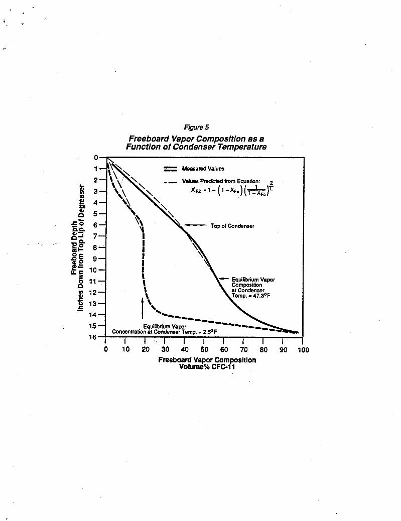
Figure 5 i l l u s t r a t e s t he r o l e t h a t the condenser temperature plays i n es tabl ishing a concentration gradient i n the freeboard zone of a degreaser. I t will be noted t h a t there is an inf lect ion point i n the depth versus composition curves and t h a t the inf lect ion point corresponds t o the vapor composition equivalent t o Po/Pt. T h i s inflection point occurs a t an elevation i n the freeboard zone t h a t is between the so-called vapor/air in te r face a t the lower condenser coils and t h e top surface of t he condenser.
CFC-11 has a boiling point and other
Figure 6 i s a confirmation of the va l id i ty of Equation 5. As predicted by Equation 5, the vapor concentration gradients along the diffusion paths (from the inf lec t ion points t o the top of the degreaser) a r e e s sen t i a l ly
I '
equivalent when condenser temperatures are employed to yield equivalent condenser parti a1 pressures.
solvents will make the degreasers and defluxers suitable for their employment not only more expensive from the standpoint of the cost of the refrigeration equipment needed, but also from the operating cost viewpoint since it requires more power to operate the low temperature refrigeration equipment.
A series of tests were undertaken to determine if the refrigeration system requirements could be minimized by employing a primary condenser, operating at around 45*F, to absorb the bulk of degreaser's heat load, with a secondary condenser, operating at around O'F, placed above the primary condenser in the freeboard zone, to establish the low partial pressure condition needed to minimize diffusion. The results of that work are shown in Figure 7. Based on those results, it is concluded that operation with a dual condenser system could be an attractive way of minimizing the investment and operating costs associated with the low temperature condensing system that will be needed with the HCFC's. However, as indicated by the results, placement of the secondary condenser in respect to-its proximity to the main condenser is a critical consideration.
Operation at the lower condenser temperatures required by the new HCFC
It is to be noted that the slope of the diffusion path curves provides a relative measure of the diffusion rate occurring under each condition of operation. The more nearly the curves approach a vertical position, the lower the diffusion rate. Operation with the main condenser maintained at the low temperature condition (Curve A) yields the curve with the steepest slope, but operation with the main condenser at 45'F with a secondary low temperature condenser positioned either immediately above (Curve 8) or with some of its coils overlapping those of the main condenser (Curve C) yields curves of comparable slope. However, as the secondary coil is displaced higher up in the freeboard zone away from the main condenser (Curve D) its effectiveness as a diffusion control device decreases. Operation with the overlapping coil arrangement (Curve C) offers the advantage over the close stacked arrangement (Curve B) in that it yields a lower overall mean vapor concentration in the freeboard zone.
introduces the likelihood that the condenser coils will become coated with a heat transfer impairing layer of frost due to contact with moisture-laden air.
Condenser operation at .below-water-freezing-temperature conditions
Test were run to determine if the need for a periodic defrosting of the secondary condenser with an attendent upset o f condenser equil i brium conditions, could be avoided by employing another low temperature peripheral coil at the top of the degreaser to prevent the infiltration of moist air into the degreaser. period of 100 hours in a 65% relative humidity atmosphere, the upper coil was found to be an effective preventer Of moisture infiltration. While the upper coil frosted readily, no frost accumulated on the secondary condenser.
In tests carried out with the degreaser refluxing over a
The third coil also exhibited a further unexpected beneficial effect as shown in Figure 8 by effecting an overall decrease in vapor concentration throughout the freeboard zone.

SUMMARY
The higher cost and physical properties of the HCFC-123 and HCFC-14lb family of solvents mandate that vapor degreasing and defluxing equipment for their employment be designed and constructed with a view of minimizing solvent emissions into the work place. The three major sources of solvent emissions have been identified and ways to eliminate or minimize the emissions from an equipment design standpoint have been developed. At the present time, the recommended emission control measures are being incorporated into new equipment that is now or soon will be available from three major equipment manufacturers. This equipment also is suitable for use with the CFC-113 solvents until the new alternative solvents are commercialized, and can be extremely effective at reducing CFC-113 usage far below current levels.
ACKNOWLEDGEMENT
following persons in the execution of this study: The author would like to acknowledge the invaluable assistance of the
o Richard L. Stewart for his help in equipment preparation, modification, and operation, and in data collection.
o Walter Dignan, Stewart Bricker and Helen Hammond for their help in performing the many gas chromatographic analyses.
o John Mobley, Detrex Technical Center, for his assistance in carrying out some of the solvent dragout tests.
o Bonnie Shaw for her help in manuscript preparation. 1
REFERENCES
1. Tech Brief TB-DP-E1 : KCD-9434 Cleaning Agent. - DuPont Company El ectroni c Dept .
2. Technical Bulletin FST-ST : KCD-9450 Cleaning Agent - DuPont Company Chemicals and Pigments Pept.
3. Bulletin - "Introducing our New Generation of Environmentally Improved Solvents - Genesol@ 2010 Solvent" - Allied Signal Inc.
4. Technical Bulletin FS-30 A : Cleaning System Design - DuPont Company FreonQ Products Division.
5. Elyse Burstein, "A Step By Step Guide to Controlling Solvent Emissions," Metal Finishing, August 1986, Pages 15-16.
6. Robert 1. Pol hamus, 'Solvent Conservation and Emission Reduction from Open - Top Solvent Cleaning Systems," Proceedings of the International Conference on CFC and Hal on A1 ternat i ves , Washington, D.C., Oct 10-11, 1989.
7 . Elyse Burstein, "Automation: The Competitive Edge," Products Finishing, March 1990, Pages 86-89.
8. Perry, Chilton, and Kirkpatrick, Chemical Engineers Handbook, McGraw-Hill Book Co.
9. Wilkie and Lee, Ind. Eng. Chem. 47, 1253 (1955)
10. Hirschfelder, Bird and Spotz, Trans. Am. SOC. Mech. Engineers, 7 l , 921 (1949).
11. Tables of Thermal Properties o f Gases, National Bureau of Standards Ci rcul ar 564
.
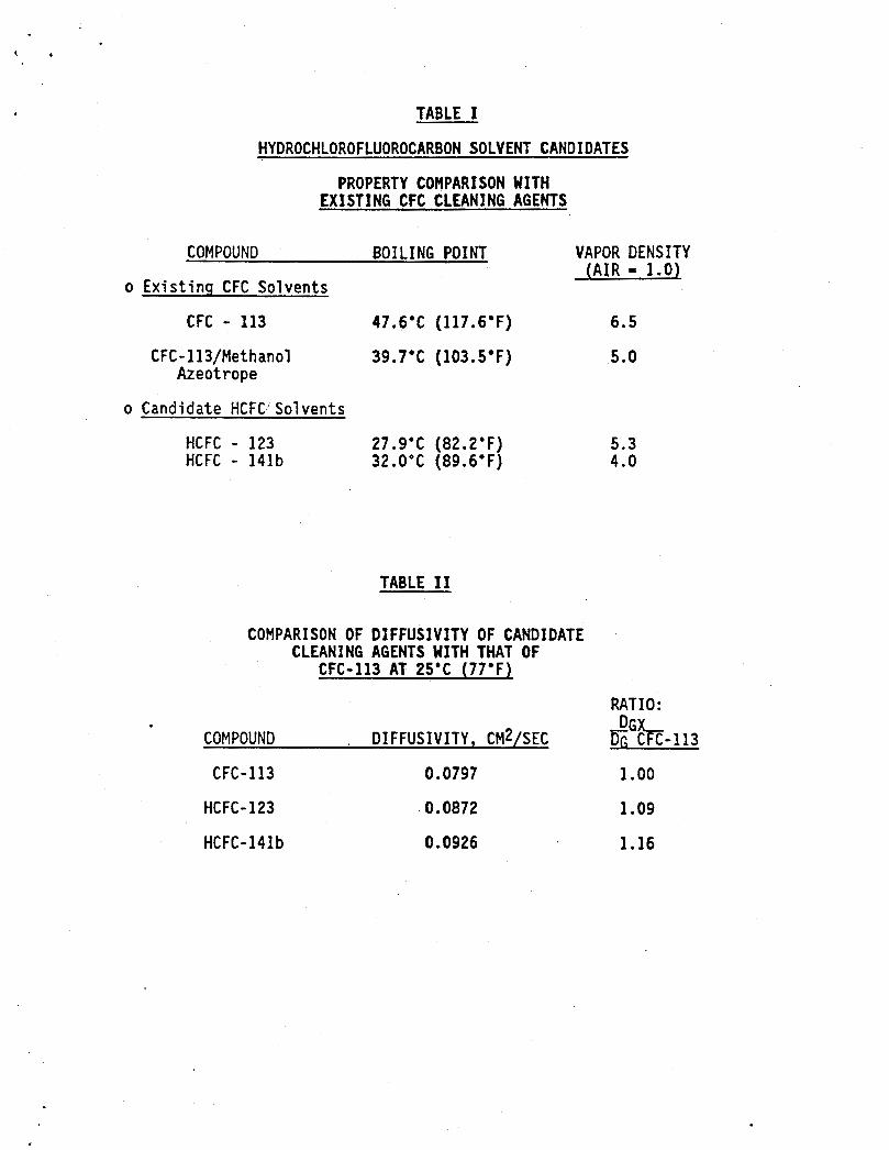
TABLE I
HYDROCHLOROFLUOROCARBON SOLVENT CANDIDATES
PROPERTY COMPARISON WITH EXISTING CFC CLEANING AGENTS
COMPOUND BOILING POINT VAPOR DENSITY ( A I R = 1.0)
o Existing CFC Solvents
CFC - 113 47.6.C (117.6.F) 6.5
CFC - 1 13/Met h an01 39.7.C (103.5.F) 5.0 Azeotrope
o Candidate HCFC! Solvents
HCFC - 123 27.9.C (82.2.F) 5.3 HCFC - 141b 32.0'C (89.6.F) 4.0
TABLE 11
COMPARISON OF DJFFUSIVITY OF CANDIDATE CLEANING AGENTS WITH THAT OF
CFC-113 AT 25'C (77'Fl
RATIO: - D G L
. DIFFUSIVITY, CM2/SEC Dc CFC-113 COMPOUND
CFC-113 0.0797 1 .oo HCFC- 123 0.0872 1.09
HCFC-14lb 0 . 0926 1.16

TABLE 111
CONDENSER TEMPERATURES REQUIRED TO YIELD EQUIVALENT VAPOR
PARTIAL PRESSURES
COMPOUND
CFC-113
CFC-11
HCFC-123
HCFC-141b
PROPERTY
CONDENSER TEMP E RATURE
CONDENSER VAPOR PARTIAL PRESSURE
( 7.2'C) 45'F 3.02 PSIA
(-14.4'C) 6'F 3.02 PSIA
(- 9'C) 15.8'F 3.02 PSIA
(- 6'C) 21.2.F 2.99 PSIA
TABLE I V
PHYSICAL PROPERTY COMPARISON
CFC-11 VS. HCFC-123 AND HCFC-14lb
CFC-11 HCFC-123 HCFC-141b
Chemical Formul a CCl3 F CF3CHC12 CH3C12 F
1 atm. Boiliqg Point,'C 23.8 27.9 32.0 , ' F 74.9 82.2 89.6
Mol ecul ar W t . 137.37 152.9 116.95
Vapor Density (Air ~1.0) 4.7 5.3 4.0
Latent Heat, BTU/1 b. 77.5 74.9 . 95.9
Specific Heat Liquid, 0.21 0.24 0.28
Liquid Viscosity 8 25'C, 0.415 0.449 0.409
BTU/(lb.)('f)
Centipoise

\
F$ure 1
Chemical Structure
CI F I I
F- C - C -CI I 1
CI F
CFC-113
F CI I 1
F - C - C - H I I F CI.
HCFC - 123
H CI I I
H-C-C-F I 1 H CI,
HCFC - 141b
E" E (3 d g 0 I E
0 v)
L
r"
30 -
20 -
10-
0-
Fgure 2
Solvent Hold- Up Po ulated Circuit Boards
Single E oard-No Soldering Fixture
\ .
Board A
Board B c
0 1 2 3 4 5 6
Residence Time In Saturated Solvent Vapor Zone Minutes
Feure 3
Solvent Hold- Up Prhted Circuit Board Assemblies
2 Populated Boards in Soldering Fixtures
90
80:: Assembly A 704 \
401 Assembly C
30
10
0 1 2 3 4 5 6 7 Residence Tlme In Saturated Solvent Vapor Zone
Minutes
i! E Q d ? I! 0 I S Q) * 0 UJ
U
-
0 1 2 3 4 5 6 7
Residence Time In Saturated Solvent Vapor Zone Minutes
1
EQlIfe 4
Solvent Hold-Up on Printed- Wring Board “D** Under Various Processing Conditions
i Y
Fgure 5 Freeboard Vapor Composition as a
Function of Condenser Temperature
1- Top of Condenser
12 "4 15 16
1 I \
[ i .-- Equilibrium Vapor
Concentration at Condenser Temp. I 2.9F I 1 ' * I
0 10 20 30 40 50 60 70 80 90 100 Freeboard Vapor Composttlon
Volume% CFC-11
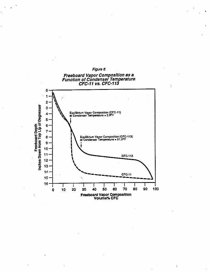
Figure 6
Freeboard Vapor Composition as a Function of Condenser Temperature
CFC-I 1 VS. CFC*113 0 1
1 A - 15 - 16 I 1 1 1 I I 1 1 1
0 i o io io do 50 60 70 ao 90 l o o Freeboard Vapor Composition
Volume% CFC

b - . *. U
Fqure 7
Freeboard Gas Composition Profile at Various Condenser Arrangements
A Main CondenserOnly Av. Temperature = 1.2OF
B M i n Condenser - Av. Temp. - 45.9 F mth Seoondary Condenser [Av. femp. =-O.eOF) e t e d mediately Above Marn Condenser
C & i n Condenser - Av. Temp. - 47.60 F w~th Semndary Condenser ~ A V . Temp: = PF) OVedaPPing
op Coils in Main Condenser
28 1 0 10 20 30 40 50 60 70 80 90 100
Freeboard Vapor Composition Volume% CFC-11

A PrimaryCondenserOniy Av. Temp. = 47.5 F
28 - 30 I I 1 I 1 I I 1 I

DuPont Electronics DuPont Company Barley Mill Plaza P.O. Box 80030 Wilmington. DE 19880-0030
PFC POLICY
1. Du Pont will only market, except in extraordinary cases, the PFC directly.
2. Du Pont will only market PFC-containing solvents for those current, non-frivolous CFC-113 applications where there is no other reasonable alternative and that application is either non-emissive or can be readily converted to an HFC product when available.
3. Du Pont will require that users of PFC products employ adequate technology to contain them during use (Minimum of Triple Guard or equivalent in cleaning equipment, Super heated vapors if liquid drag out is or could be substantial, and Carbon absorption if the product is used in such a manner that it cannot be contained and will evaporate into the air).
4. Du Pont will require that customers recycle or safely destroy PFC products subsequent to use.
5 . Du Pont will provide a recycle and reclamation service for PFC users.
6 . Du Pont will terminate marketing of PFC solvents for potentially emissive uses when an HFC or other suitable replacement is available and in no case beyond 5 years.
7 . Du Pont will qualify and routinely audit all PFC solvent customers to ascertain that they meet these guidelines.
c
9/4/92
ET 69 3C