Embed Size (px)
Citation preview
GW-1
GLASSES, WINDOW SYSTEM & MIRRORS
I BODY
CONTENTS
C
D
E
F
G
H
J
K
L
M
SECTION GWA
B
GW
Revision: March 2006 2007 Quest
PRECAUTIONS .......................................................... 4Precautions for Supplemental Restraint System (SRS) “AIR BAG” and “SEAT BELT PRE-TEN-SIONER” .................................................................. 4Handling for Adhesive and Primer ........................... 4
PREPARATION ........................................................... 5Special Service Tool ................................................. 5Commercial Service Tool ......................................... 5
SQUEAK AND RATTLE TROUBLE DIAGNOSES ..... 6Work Flow ................................................................ 6
CUSTOMER INTERVIEW ..................................... 6DUPLICATE THE NOISE AND TEST DRIVE ....... 7CHECK RELATED SERVICE BULLETINS ........... 7LOCATE THE NOISE AND IDENTIFY THE ROOT CAUSE ...................................................... 7REPAIR THE CAUSE ........................................... 7CONFIRM THE REPAIR ....................................... 8
Generic Squeak and Rattle Troubleshooting ........... 8INSTRUMENT PANEL .......................................... 8CENTER CONSOLE ............................................. 8DOORS ................................................................. 8TRUNK .................................................................. 9SUNROOF/HEADLINER ....................................... 9OVERHEAD CONSOLE (FRONT AND REAR) ..... 9SEATS ................................................................... 9UNDERHOOD ....................................................... 9
Diagnostic Worksheet ............................................ 10WINDSHIELD GLASS .............................................. 12
Removal and Installation ........................................ 12REMOVAL ........................................................... 12INSTALLATION ................................................... 12
REAR WINDOW GLASS AND MOLDING ............... 14Removal and Installation ........................................ 14
REMOVAL ........................................................... 14INSTALLATION ................................................... 14
SKYVIEW ROOF ...................................................... 16Removal and Installation ........................................ 16
REMOVAL ........................................................... 16INSTALLATION ................................................... 16
POWER WINDOW SYSTEM .................................... 18
Component Parts and Harness Connector Location ... 18System Description ................................................. 18
MANUAL OPERATION ........................................ 19AUTO OPERATION ............................................. 20POWER WINDOW SERIAL LINK ....................... 20POWER WINDOW LOCK ................................... 21RETAINED POWER OPERATION ...................... 21ANTI-PINCH SYSTEM ........................................ 21POWER WINDOW CONTROL BY THE FRONT DOOR LOCK ASSEMBLY LH (KEY CYLINDER SWITCH) ............................................................. 21
CAN Communication System Description .............. 21Schematic (Without Rear Power Vent Windows) ... 22Wiring Diagram — WINDOW — (Without Rear Power Vent Windows) ............................................ 23Main Power Window and Door Lock/Unlock Switch (Without Rear Power Vent Windows) Harness Con-nector Terminal Layout ........................................... 26Terminal and Reference Value for Main Power Win-dow and Door Lock/Unlock Switch (Without Rear Power Vent Windows) ............................................ 26Power Window and Door Lock/Unlock Switch RH (Without Rear Power Vent Windows) Harness Con-nector Terminal Layout ........................................... 27Terminal and Reference Value for Power Window and Door Lock/ Unlock Switch RH (Without Rear Power Vent Windows) ............................................ 27Terminal and Reference Value for BCM (Without Rear Power Vent Windows) .................................... 28Schematic (With Rear Power Vent Windows) ........ 29Wiring Diagram — WINDOW — (With Rear Power Vent Windows) ........................................................ 30Main Power Window and Door Lock/Unlock Switch (With Rear Power Vent Windows) Harness Con-nector Terminal Layout ........................................... 34Terminal and Reference Value for Main Power Win-dow and Door Lock/Unlock Switch (With Rear Power Vent Windows) ............................................ 34Power Window and Door Lock/Unlock Switch RH (With Rear Power Vent Windows) Harness Con-

GW-2Revision: March 2006 2007 Quest
nector Terminal Layout ........................................... 35Terminal and Reference Value for Power Window and Door Lock/Unlock Switch RH (With Rear Power Vent Windows) ........................................................ 35Terminal and Reference Value for BCM (With Rear Power Vent Windows) ............................................ 36Work Flow ............................................................... 37CONSULT-II Function (BCM) .................................. 37
CONSULT-II START PROCEDURE .................... 37ACTIVE TEST ..................................................... 37WORK SUPPORT ............................................... 37DATA MONITOR .................................................. 37
Symptom Chart (Without Rear Power Vent Win-dows) ...................................................................... 38Symptom Chart (With Rear Power Vent Windows) ... 39BCM Power Supply and Ground Circuit Check ...... 39Main Power Window and Door Lock/Unlock Switch Power Supply Circuit Check (Without Rear Power Vent Windows) ........................................................ 40Main Power Window and Door Lock/Unlock Switch Power Supply Circuit Check (With Rear Power Vent Windows) ................................................................ 41Power Window and Door Lock/Unlock Switch RH Power Supply and Ground Circuit Check ............... 42Front Power Window Motor LH Circuit Check ........ 44Front Power Window Motor RH Circuit Check (With-out Rear Power Vent Windows) .............................. 44Front Power Window Motor RH Circuit Check (With Rear Power Vent Windows) .................................... 45Limit Switch Circuit Check Front LH (Without Rear Power Vent Windows) ............................................ 46Limit Switch Circuit Check Front LH (With Rear Power Vent Windows) ............................................ 48Limit Switch Circuit Check Front RH (Without Rear Power Vent Windows) ............................................ 51Limit Switch Circuit Check Front RH (With Rear Power Vent Windows) ............................................ 53Encoder Circuit Check Front LH (Without Rear Power Vent Windows) ............................................ 56Encoder Circuit Check Front LH (With Rear Power Vent Windows) ........................................................ 58Encoder Circuit Check Front RH (Without Rear Power Vent Windows) ............................................ 61Encoder Circuit Check Front RH (With Rear Power Vent Windows) ........................................................ 63Door Switch Check ................................................. 66Front Door Lock Assembly LH (Key Cylinder Switch) Check (Without Rear Power Vent Windows) .......... 67Front Door Lock Assembly LH (Key Cylinder Switch) Check (With Rear Power Vent Windows) ............... 69Power Window Serial Link Check Front LH and RH (Without Rear Power Vent Windows) ..................... 71Power Window Serial Link Check Front LH and RH (With Rear Power Vent Windows) .......................... 73Rear Power Vent Window Motor LH Circuit Check ... 75Rear Power Vent Window Motor RH Circuit Check ... 76
FRONT DOOR GLASS AND REGULATOR .............77Removal and Installation .........................................77
FRONT DOOR GLASS ........................................77INSTALLATION ...................................................78FRONT DOOR GLASS REGULATOR .................79INSPECTION AFTER REMOVAL ........................79INSTALLATION ...................................................79DISASSEMBLY ....................................................79ASSEMBLY ..........................................................79FITTING INSPECTION AND SETTING AFTER INSTALLATION ....................................................79SETTING OF LIMIT SWITCH ..............................80
SLIDE DOOR GLASS ...............................................81Removal and Installation .........................................81
REMOVAL ............................................................81INSTALLATION ....................................................81
SIDE WINDOW GLASS ............................................83Removal and Installation (without Rear Power Vent Windows) ................................................................83
REMOVAL ............................................................83INSTALLATION ....................................................83
Removal and Installation (with Rear Power Vent Windows) ................................................................84
REMOVAL ............................................................84INSTALLATION ....................................................84
INSIDE MIRROR .......................................................85Wiring Diagram — I/MIRR — .................................85Removal and Installation .........................................86
REMOVAL ............................................................86INSTALLATION ....................................................86
REAR WINDOW DEFOGGER ..................................87Component Parts and Harness Connector Location ...87System Description .................................................87CAN Communication System Description ..............88Schematic ...............................................................89Wiring Diagram — DEF — ......................................90Terminal and Reference Value for BCM ..................93Terminal and Reference Value for IPDM E/R ..........93Work Flow ...............................................................93CONSULT-II Function (BCM) ..................................93
CONSULT-II START PROCEDURE .....................93DATA MONITOR ..................................................93ACTIVE TEST ......................................................93
Trouble Diagnoses Symptom Chart ........................93BCM Power Supply and Ground Circuit Check ......94Rear Window Defogger Switch Circuit Check .........95Rear Window Defogger Power Supply Circuit Check ......................................................................96Rear Window Defogger Circuit Check ....................98Door Mirror Defogger Power Supply Circuit Check ...99Door Mirror LH Defogger Circuit Check ................100Door Mirror RH Defogger Circuit Check ...............101Rear Window Defogger Signal Check ..................102Filament Check .....................................................103Filament Repair .....................................................103
REPAIR EQUIPMENT .......................................103REPAIRING PROCEDURE ...............................104
DOOR MIRROR .......................................................105Automatic Drive Positioner Reverse Tilt Mirror .....105

GW-3
C
D
E
F
G
H
J
K
L
M
A
B
GW
Revision: March 2006 2007 Quest
Wiring Diagram — MIRROR — ........................... 106Door Mirror Assembly .......................................... 107
REMOVAL AND INSTALLATION ...................... 107
REMOVAL ......................................................... 107Door Mirror Glass ................................................. 107
REMOVAL AND INSTALLATION ...................... 107INSTALLATION ................................................. 108

GW-4
PRECAUTIONS
Revision: March 2006 2007 Quest
PRECAUTIONS PFP:00001
Precautions for Supplemental Restraint System (SRS) “AIR BAG” and “SEAT BELT PRE-TENSIONER” EIS007H8
The Supplemental Restraint System such as “AIR BAG” and “SEAT BELT PRE-TENSIONER”, used alongwith a front seat belt, helps to reduce the risk or severity of injury to the driver and front passenger for certaintypes of collision. This system includes seat belt switch inputs and dual stage front air bag modules. The SRSsystem uses the seat belt switches to determine the front air bag deployment, and may only deploy one frontair bag, depending on the severity of a collision and whether the front occupants are belted or unbelted.Information necessary to service the system safely is included in the SRS and SB section of this Service Man-ual.WARNING:� To avoid rendering the SRS inoperative, which could increase the risk of personal injury or death
in the event of a collision which would result in air bag inflation, all maintenance must be per-formed by an authorized NISSAN/INFINITI dealer.
� Improper maintenance, including incorrect removal and installation of the SRS, can lead to per-sonal injury caused by unintentional activation of the system. For removal of Spiral Cable and AirBag Module, see the SRS section.
� Do not use electrical test equipment on any circuit related to the SRS unless instructed to in thisService Manual. SRS wiring harnesses can be identified by yellow and/or orange harnesses orharness connectors.
Handling for Adhesive and Primer EIS007H9
� Do not use an adhesive which is past its usable date. Shelf life of this product is limited to six months afterthe date of manufacture. Carefully adhere to the expiration or manufacture date printed on the box.
� Keep primers and adhesive in a cool, dry place. Ideally, they should be stored in a refrigerator.� Open the seal of the primer and adhesive just before application. Discard the remainder.� Before application, be sure to shake the primer container to stir the contents. If any floating material is
found, do not use it.� If any primer or adhesive contacts the skin, wipe it off with gasoline or equivalent and wash the skin with
soap.� When using primer and adhesive, always observe the precautions in the instruction manual.

PREPARATION
GW-5
C
D
E
F
G
H
J
K
L
M
A
B
GW
Revision: March 2006 2007 Quest
PREPARATION PFP:00002
Special Service Tool EIS007HB
The actual shapes of Kent-Moore tools may differ from those of special service tools illustrated here.
Commercial Service Tool EIS007HC
Tool number(Kent-Moore No.)Tool name
Description
—(J-39570)Chassis ear
Locating the noise
—(J-43980)NISSAN Squeak and Rat-tle Kit
Repairing the cause of noise
SIIA0993E
SIIA0994E
(Kent-Moore No.)Tool name
Description
(J-39565)Engine ear
Locating the noise
( – )Suction lifter
Holding the door glass
SIIA0995E
LIIA1991E

GW-6
SQUEAK AND RATTLE TROUBLE DIAGNOSES
Revision: March 2006 2007 Quest
SQUEAK AND RATTLE TROUBLE DIAGNOSES PFP:00000
Work Flow EIS007HD
CUSTOMER INTERVIEWInterview the customer if possible, to determine the conditions that exist when the noise occurs. Use the Diag-nostic Worksheet during the interview to document the facts and conditions when the noise occurs and anycustomer's comments; refer to GW-10, "Diagnostic Worksheet" . This information is necessary to duplicate theconditions that exist when the noise occurs.� The customer may not be able to provide a detailed description or the location of the noise. Attempt to
obtain all the facts and conditions that exist when the noise occurs (or does not occur).� If there is more than one noise in the vehicle, be sure to diagnose and repair the noise that the customer
is concerned about. This can be accomplished by test driving the vehicle with the customer. � After identifying the type of noise, isolate the noise in terms of its characteristics. The noise characteristics
are provided so the customer, service adviser and technician are all speaking the same language whendefining the noise.
� Squeak —(Like tennis shoes on a clean floor)Squeak characteristics include the light contact/fast movement/brought on by road conditions/hard sur-faces = higher pitch noise/softer surfaces = lower pitch noises/edge to surface = chirping.
� Creak—(Like walking on an old wooden floor)Creak characteristics include firm contact/slow movement/twisting with a rotational movement/pitchdependent on materials/often brought on by activity.
� Rattle—(Like shaking a baby rattle)Rattle characteristics include the fast repeated contact/vibration or similar movement/loose parts/missingclip or fastener/incorrect clearance.
� Knock —(Like a knock on a door)Knock characteristics include hollow sounding/sometimes repeating/often brought on by driver action.
� Tick—(Like a clock second hand)Tick characteristics include gentle contacting of light materials/loose components/can be caused by driveraction or road conditions.
� Thump—(Heavy, muffled knock noise)Thump characteristics include softer knock/dead sound often brought on by activity.
� Buzz—(Like a bumble bee)Buzz characteristics include high frequency rattle/firm contact.
� Often the degree of acceptable noise level will vary depending upon the person. A noise that you mayjudge as acceptable may be very irritating to the customer.
� Weather conditions, especially humidity and temperature, may have a great effect on noise level.
SBT842

SQUEAK AND RATTLE TROUBLE DIAGNOSES
GW-7
C
D
E
F
G
H
J
K
L
M
A
B
GW
Revision: March 2006 2007 Quest
DUPLICATE THE NOISE AND TEST DRIVEIf possible, drive the vehicle with the customer until the noise is duplicated. Note any additional information onthe Diagnostic Worksheet regarding the conditions or location of the noise. This information can be used toduplicate the same conditions when you confirm the repair.If the noise can be duplicated easily during the test drive, to help identify the source of the noise, try to dupli-cate the noise with the vehicle stopped by doing one or all of the following:1) Close a door.2) Tap or push/pull around the area where the noise appears to be coming from.3) Rev the engine.4) Use a floor jack to recreate vehicle “twist”.5) At idle, apply engine load (electrical load, half-clutch on M/T model, drive position on A/T model).6) Raise the vehicle on a hoist and hit a tire with a rubber hammer.� Drive the vehicle and attempt to duplicate the conditions the customer states exist when the noise occurs.� If it is difficult to duplicate the noise, drive the vehicle slowly on an undulating or rough road to stress the
vehicle body.
CHECK RELATED SERVICE BULLETINSAfter verifying the customer concern or symptom, check ASIST for Technical Service Bulletins (TSBs) relatedto that concern or symptom.If a TSB relates to the symptom, follow the procedure to repair the noise.
LOCATE THE NOISE AND IDENTIFY THE ROOT CAUSE1. Narrow down the noise to a general area.To help pinpoint the source of the noise, use a listening tool
(Chassis Ear: J-39570, Engine Ear: J-39565 and mechanic's stethoscope).2. Narrow down the noise to a more specific area and identify the cause of the noise by:� removing the components in the area that you suspect the noise is coming from.
Do not use too much force when removing clips and fasteners, otherwise clips and fasteners can be bro-ken or lost during the repair, resulting in the creation of new noise.
� tapping or pushing/pulling the component that you suspect is causing the noise.Do not tap or push/pull the component with excessive force, otherwise the noise will be eliminated onlytemporarily.
� feeling for a vibration with your hand by touching the component(s) that you suspect is (are) causing thenoise.
� placing a piece of paper between components that you suspect are causing the noise.� looking for loose components and contact marks.
Refer to GW-8, "Generic Squeak and Rattle Troubleshooting" .
REPAIR THE CAUSE � If the cause is a loose component, tighten the component securely.� If the cause is insufficient clearance between components:– separate components by repositioning or loosening and retightening the component, if possible.– insulate components with a suitable insulator such as urethane pads, foam blocks, felt cloth tape or ure-
thane tape. A NISSAN Squeak and Rattle Kit (J-43980) is available through your authorized NISSANParts Department.
CAUTION:Do not use excessive force as many components are constructed of plastic and may be damaged.Always check with the Parts Department for the latest parts information.The following materials are contained in the NISSAN Squeak and Rattle Kit (J-43980). Each item can beordered separately as needed.URETHANE PADS [1.5 mm (0.059 in) thick]Insulates connectors, harness, etc.76268-9E005: 100×135 mm (3.94×5.31 in)/76884-71L01: 60×85 mm (2.36×3.35 in)/76884-71L02: 15×25mm (0.59×0.98 in)INSULATOR (Foam blocks)Insulates components from contact. Can be used to fill space behind a panel.73982-9E000: 45 mm (1.77 in) thick, 50×50 mm (1.97×1.97 in)/73982-50Y00: 10 mm (0.39 in) thick,50×50 mm (1.97×1.97 in)INSULATOR (Light foam block)

GW-8
SQUEAK AND RATTLE TROUBLE DIAGNOSES
Revision: March 2006 2007 Quest
80845-71L00: 30 mm (1.18 in) thick, 30×50 mm (1.18×1.97 in)FELT CLOTH TAPEUsed to insulate where movement does not occur. Ideal for instrument panel applications.68370-4B000: 15×25 mm (0.59×0.98 in) pad/68239-13E00: 5 mm (0.20 in) wide tape roll. The following mate-rials not found in the kit can also be used to repair squeaks and rattles.UHMW (TEFLON) TAPE Insulates where slight movement is present. Ideal for instrument panel applications.SILICONE GREASEUsed instead of UHMW tape that will be visible or not fit.Note: Will only last a few months.SILICONE SPRAYUse when grease cannot be applied.DUCT TAPEUse to eliminate movement.
CONFIRM THE REPAIRConfirm that the cause of a noise is repaired by test driving the vehicle. Operate the vehicle under the sameconditions as when the noise originally occurred. Refer to the notes on the Diagnostic Worksheet.
Generic Squeak and Rattle Troubleshooting EIS007HE
Refer to Table of Contents for specific component removal and installation information.
INSTRUMENT PANELMost incidents are caused by contact and movement between:1. The cluster lid A and instrument panel2. Acrylic lens and combination meter housing3. Instrument panel to front pillar garnish4. Instrument panel to windshield5. Instrument panel mounting pins6. Wiring harnesses behind the combination meter 7. A/C defroster duct and duct jointThese incidents can usually be located by tapping or moving the components to duplicate the noise or bypressing on the components while driving to stop the noise. Most of these incidents can be repaired by apply-ing felt cloth tape or silicone spray (in hard to reach areas). Urethane pads can be used to insulate wiring har-ness.CAUTION:Do not use silicone spray to isolate a squeak or rattle. If you saturate the area with silicone, you willnot be able to recheck the repair.
CENTER CONSOLEComponents to pay attention to include:1. Shifter assembly cover to finisher2. A/C control unit and cluster lid C3. Wiring harnesses behind audio and A/C control unitThe instrument panel repair and isolation procedures also apply to the center console.
DOORSPay attention to the:1. Finisher and inner panel making a slapping noise2. Inside handle escutcheon to door finisher3. Wiring harnesses tapping 4. Door striker out of alignment causing a popping noise on starts and stopsTapping or moving the components or pressing on them while driving to duplicate the conditions can isolatemany of these incidents. You can usually insulate the areas with felt cloth tape or insulator foam blocks fromthe NISSAN Squeak and Rattle Kit (J-43980) to repair the noise.

SQUEAK AND RATTLE TROUBLE DIAGNOSES
GW-9
C
D
E
F
G
H
J
K
L
M
A
B
GW
Revision: March 2006 2007 Quest
TRUNKTrunk noises are often caused by a loose jack or loose items put into the trunk by the owner.In addition look for:1. Trunk lid bumpers out of adjustment2. Trunk lid striker out of adjustment 3. The trunk lid torsion bars knocking together4. A loose license plate or bracketMost of these incidents can be repaired by adjusting, securing or insulating the item(s) or component(s) caus-ing the noise.
SUNROOF/HEADLINERNoises in the sunroof/headliner area can often be traced to one of the following:1. Sunroof lid, rail, linkage or seals making a rattle or light knocking noise2. Sun visor shaft shaking in the holder3. Front or rear windshield touching headliner and squeaking Again, pressing on the components to stop the noise while duplicating the conditions can isolate most of theseincidents. Repairs usually consist of insulating with felt cloth tape.
OVERHEAD CONSOLE (FRONT AND REAR)Overhead console noises are often caused by the console panel clips not being engaged correctly. Most ofthese incidents are repaired by pushing up on the console at the clip locations until the clips engage.In addition look for:1. Loose harness or harness connectors.2. Front console map/reading lamp lense loose.3. Loose screws at console attachment points.
SEATSWhen isolating seat noise it's important to note the position the seat is in and the load placed on the seat whenthe noise is present. These conditions should be duplicated when verifying and isolating the cause of thenoise.Cause of seat noise include: 1. Headrest rods and holder 2. A squeak between the seat pad cushion and frame 3. The rear seatback lock and bracket These noises can be isolated by moving or pressing on the suspected components while duplicating the con-ditions under which the noise occurs. Most of these incidents can be repaired by repositioning the componentor applying urethane tape to the contact area.
UNDERHOODSome interior noise may be caused by components under the hood or on the engine wall. The noise is thentransmitted into the passenger compartment.Causes of transmitted underhood noise include:1. Any component mounted to the engine wall2. Components that pass through the engine wall3. Engine wall mounts and connectors4. Loose radiator mounting pins5. Hood bumpers out of adjustment 6. Hood striker out of adjustmentThese noises can be difficult to isolate since they cannot be reached from the interior of the vehicle. The bestmethod is to secure, move or insulate one component at a time and test drive the vehicle. Also, engine RPMor load can be changed to isolate the noise. Repairs can usually be made by moving, adjusting, securing, orinsulating the component causing the noise.

GW-10
SQUEAK AND RATTLE TROUBLE DIAGNOSES
Revision: March 2006 2007 Quest
Diagnostic Worksheet EIS007HF
LAIA0071E

SQUEAK AND RATTLE TROUBLE DIAGNOSES
GW-11
C
D
E
F
G
H
J
K
L
M
A
B
GW
Revision: March 2006 2007 Quest
LAIA0072E

GW-12
WINDSHIELD GLASS
Revision: March 2006 2007 Quest
WINDSHIELD GLASS PFP:72712
Removal and Installation EIS007HG
REMOVAL1. Remove inside mirror. Refer to GW-86, "Removal and Installation" .2. Partially remove the headliner (front edge). Refer to EI-41, "HEADLINING" .3. Remove cowl top cover. Refer to EI-19, "Removal and Installation" .4. Apply protective tape around the windshield glass to protect the painted surface from damage.� Remove glass using piano wire or power cutting tool and an inflatable pump bag.� If the windshield glass is to be reused, mark the body and the glass with mating marks.WARNING:When cutting the glass from the vehicle, always wear safety glasses and heavy gloves to help preventglass splinters from entering your eyes or cutting your hands.CAUTION:� When a windshield glass is to be reused, do not use a cutting knife or power cutting tool.� Be careful not to scratch the glass when removing.� Do set or stand glass on its edge. Small chips may develop into cracks.
INSTALLATIONInstallation is in the reverse order of removal.� Use a genuine NISSAN Urethane Adhesive Kit (if available) or equivalent and follow the instructions fur-
nished with it.� While the urethane adhesive is curing, open a door window. This will prevent the glass from being forced
out by passenger compartment air pressure when a door is closed.
LIIA0652E
PIIA0186E

WINDSHIELD GLASS
GW-13
C
D
E
F
G
H
J
K
L
M
A
B
GW
Revision: March 2006 2007 Quest
� The molding must be installed securely so that it is in position and leaves no gap.� Inform the customer that the vehicle should remain stationary until the urethane adhesive has completely
cured (preferably 24 hours). Curing time varies with temperature and humidity.WARNING:� Keep heat and open flames away as primers and adhesive are flammable.� The materials contained in the kit are harmful if swallowed, and may irritate skin and eyes. Avoid
contact with the skin and eyes.� Use in an open, well ventilated location. Avoid breathing the vapors. They can be harmful if
inhaled. If affected by vapor inhalation, immediately move to an area with fresh air.� Driving the vehicle before the urethane adhesive has completely cured may affect the perfor-
mance of the windshield in case of an accident.CAUTION:� Do not use an adhesive which is past its usable term. Shelf life of this product is limited to six
months after the date of manufacture. Carefully adhere to the expiration or manufacture dateprinted on the box.
� Keep primers and adhesive in a cool, dry place. Ideally, they should be stored in a refrigerator.� Do not leave primers or adhesive cartridge unattended with their caps open or off.� The vehicle should not be driven for at least 24 hours or until the urethane adhesive has com-
pletely cured. Curing time varies depending on temperature and humidities. The curing time willincrease under lower temperatures and lower humidities.
Repairing Water Leaks for WindshieldLeaks can be repaired without removing and reinstalling glass.If water is leaking between the urethane adhesive material and body or glass, determine the extent of leakage. This can be done by applying water to the windshield area while pushing glass outward.To stop the leak, apply primer (if necessary) and then urethane adhesive to the leak point.
LIIA0850E

GW-14
REAR WINDOW GLASS AND MOLDING
Revision: March 2006 2007 Quest
REAR WINDOW GLASS AND MOLDING PFP:79712
Removal and Installation EIS007HH
REMOVAL1. Remove the rear wiper arm and motor. Refer to EI-33, "BODY SIDE TRIM" .2. Remove the connectors and grounds for the rear window defogger.� Remove glass using piano wire or power cutting tool and an
inflatable pump bag.� If the rear window glass is to be reused, mark the body and the
glass with mating marks.WARNING:When cutting the glass from the vehicle, always wear safetyglasses and heavy gloves to help prevent glass splinters fromentering your eyes or cutting your hands.CAUTION:� When a windshield glass is to be reused, do not use a cut-
ting knife or power cutting tool. � Be careful not to scratch the glass when removing.� Do not set or stand the glass on its edge. Small chips may develop into cracks.
INSTALLATIONInstallation is in the reverse order of removal.� Use a genuine NISSAN Urethane Adhesive Kit (if available) or equivalent and follow the instructions fur-
nished with it.� While the urethane adhesive is curing, open a door window. This will prevent the glass from being forced
out by passenger compartment air pressure when a door is closed.� The molding must be installed securely so that it is in position and leaves no gap.
1. Foam dam 2. Back door window glass 3. Bond
4. Back door outer panel
LIIA1562E
SBF034B

REAR WINDOW GLASS AND MOLDING
GW-15
C
D
E
F
G
H
J
K
L
M
A
B
GW
Revision: March 2006 2007 Quest
� Check gap along bottom to confirm that glass does not contact sheet metal.� Inform the customer that the vehicle should remain stationary until the urethane adhesive has completely
cured (preferably 24 hours). Curing time varies with temperature and humidity.WARNING:� Keep heat and open flames away as primers and adhesive are flammable.� The materials contained in the kit are harmful if swallowed, and may irritate skin and eyes. Avoid
contact with the skin and eyes.� Use in an open, well ventilated location. Avoid breathing the vapors. They can be harmful if
inhaled. If affected by vapor inhalation, immediately move to an area with fresh air.� Driving the vehicle before the urethane adhesive has completely cured may affect the perfor-
mance of the windshield in case of an accident.CAUTION:� Do not use an adhesive which is past its usable term. Shelf life of this product is limited to six
months after the date of manufacture. Carefully adhere to the expiration or manufacture dateprinted on the box.
� Keep primers and adhesive in a cool, dry place. Ideally, they should be stored in a refrigerator.� Do not leave primers or adhesive cartridge unattended with their caps open or off.� The vehicle should not be driven for at least 24 hours or until the urethane adhesive has com-
pletely cured. Curing time varies depending on temperature and humidity. The curing time willincrease under lower temperatures and lower humidities.
Repairing Water leaks for Rear Window GlassLeaks can be repaired without removing or reinstalling glass.If water is leaking between urethane adhesive material and body or glass, determine the extent of leakage.This can be done by applying water to the rear window area while pushing glass outward.To stop leak, apply primer (if necessary) and then urethane adhesive to the leak point.

GW-16
SKYVIEW ROOF
Revision: March 2006 2007 Quest
SKYVIEW ROOF PFP:79700
Removal and Installation EIS007HI
REMOVAL1. Remove the headliner. Refer to EI-41, "HEADLINING" .2. Apply protective tape around the skyview roof glass to protect the painted surface from damage.3. Remove glass using piano wire or power cutting tool and an inflatable pump bag.WARNING:When cutting the glass from the vehicle, always wear safety glasses and heavy gloves to help preventglass splinters from entering your eyes or cutting your hands.CAUTION:� When a skyview roof glass is to be reused, do not use a cutting knife or power cutting tool.� Be careful not to scratch the glass when removing.� Do not set or stand the glass on its edge. Small chips may develop into cracks.
INSTALLATIONInstallation is in the reverse order of removal.� Use a genuine NISSAN Urethane Adhesive Kit (if available) or equivalent and follow the instructions fur-
nished with it.� While the urethane adhesive is curing, open a window. This will prevent the glass from being forced out by
passenger compartment air pressure when a door is closed.� The rubber seal must be installed securely so that it is in position and leaves no gap.� Inform customer that the vehicle should remain stationary until the urethane adhesive has completely
cured (preferably 24 hours). Curing time varies with temperature and humidity.
LIIA0851E

SKYVIEW ROOF
GW-17
C
D
E
F
G
H
J
K
L
M
A
B
GW
Revision: March 2006 2007 Quest
WARNING:� Keep heat and open flames away as primers and adhesives are flammable.� The materials contained in the kit are harmful if swallowed, and may irritate skin and eyes. Avoid
contact with the skin and eyes.� Use in an open, well ventilated location. Avoid breathing the vapors. They can be harmful if
inhaled. if affected by vapor inhalation, immediately move to area with fresh air.� Driving the vehicle before urethane adhesive has completely cured may affect the performance of
the skyview roof in case of an accident.CAUTION:� Do not use an adhesive which is past its usable term. Shelf life of this product is limited to six
months after the date of manufacture. Carefully adhere to the expiration or manufacture dateprinted on the box.
� Keep primers and adhesives in a cool dry place. ideally they should be stored in a refrigerator.� Do not leave primers and adhesive cartridge unattended with their caps off.� The vehicle should not be driven for at least 24 hours or until the urethane adhesive has com-
pletely cured. Curing time depends on temperature and humidity. The curing time will increaseunder lower temperature and lower humidities.
Repairing Water Leaks for Skyview Roof GlassLeaks can be repaired without removing and reinstalling glass.If water is leaking between the urethane adhesive material and body or glass, determine the extent of leakage.This can be done by applying water to the glass area while pushing glass outward.To stop the leak, apply primer (if necessary) and then urethane adhesive to the leak point.

GW-18
POWER WINDOW SYSTEM
Revision: March 2006 2007 Quest
POWER WINDOW SYSTEM PFP:25401
Component Parts and Harness Connector Location EIS007HJ
System Description EIS007HK
Power is supplied at all times� from 50A fusible link (letter j , located in the fuse and fusible link box)� to BCM terminal 70� through BCM terminal 69� to main power window and door lock/unlock switch terminal 1 (without rear power vent windows) or 19
(with rear power vent windows)� to power window and door lock/unlock switch RH terminal 10.With ignition switch in ON or START position, power is supplied� through 10A fuse [No.16, located in the fuse block (J/B)]� to BCM terminal 38� through BCM terminal 68� to main power window and door lock/unlock switch terminal 10.With ignition switch in ACC or ON position, power is supplied
1. A. Rear power vent window motor LH B52, RH B147B. Condenser-3 B65, -4 B68 (view with rear finishers removed)
2. A. A-pillar LHB. BCM M18, M19, M20 (view with instrument panel removed)
3. A. Main power window and door lock/unlock switch D7, D8Power window and door lock/unlock switch RH D105B. Front door switch LH B8, RH B108C. Front door lock assembly LH (key cylinder switch) D14
4. Front power window motor LH D9, RH D104 (view with door finisher removed)
LIIA2453E

POWER WINDOW SYSTEM
GW-19
C
D
E
F
G
H
J
K
L
M
A
B
GW
Revision: March 2006 2007 Quest
� through 10A fuse [No. 4, located in the fuse block (J/B)]� to BCM terminal 11.Ground is supplied� to BCM terminal 67� to front door lock assembly LH (key cylinder switch) terminal 5� to main power window and door lock/unlock switch terminal 15 (without rear power vent windows) or 17
(with rear power vent windows)� to power window and door lock/unlock switch RH terminal 11� through body grounds M57, M61 and M79.
MANUAL OPERATIONFront Door LHWINDOW UPWhen the front LH switch in the main power window and door lock/unlock switch is pressed in the up position,power is supplied� through main power window and door lock/unlock switch terminal 8� to front power window motor LH terminal 2.Ground is supplied� through main power window and door lock/unlock switch terminal 11� to front power window motor LH terminal 1.Then, the motor raises the window until the switch is released.WINDOW DOWNWhen the front LH switch in the main power window and door lock/unlock switch is pressed in the down posi-tion, power is supplied� through main power window and door lock/unlock switch terminal 11� to front power window motor LH terminal 1.Ground is supplied� through main power window and door lock/unlock switch terminal 8� to front power window motor LH terminal 2.Then, the motor lowers the window until the switch is released.
Front Door RH POWER WINDOW AND DOOR LOCK/UNLOCK SWITCH RH OPERATIONWINDOW UPWhen the power window and door lock/unlock switch RH is pressed in the up position, power is supplied� through power window and door lock/unlock switch RH terminal 8� to front power window motor RH terminal 2.Ground is supplied� through power window and door lock/unlock switch RH terminal 9� to front power window motor RH terminal 1.Then, the motor raises the window until the switch is released.WINDOW DOWN When the power window and door lock/unlock switch RH is pressed in the down position, power is supplied� through power window and door lock/unlock switch RH terminal 9� to front power window motor RH terminal 1.Ground is supplied� through power window and door lock/unlock switch RH terminal 8� to front power window motor RH terminal 2.Then, the motor lowers the window until the switch is released.MAIN POWER WINDOW AND DOOR LOCK/UNLOCK SWITCH OPERATIONPower window serial link signal is sent� though main power window and door lock/unlock switch terminal 12 (without rear power vent windows) or
14 (with rear power vent windows)

GW-20
POWER WINDOW SYSTEM
Revision: March 2006 2007 Quest
� to power window and door lock/unlock switch RH terminal 16.The operation of power window after receiving the signal is the same as operating the power window withpower window and door lock/unlock switch RH.VENT WINDOW CLOSE (WITH REAR POWER VENT WINDOWS)When the main power window and door lock/unlock switch (rear LH) is pressed in the close position, power issupplied� through main power window and door lock/unlock switch terminal 1� to rear power vent window motor LH terminal 1.Ground is supplied� through main power window and door lock/unlock switch terminal 3� to rear power vent window motor LH terminal 2.Then, the motor closes the window until the switch is released.When the main power window and door lock/unlock switch (rear RH) is pressed in the close position, power issupplied� through main power window and door lock/unlock switch terminal 7� to rear power vent window motor RH terminal 1.Ground is supplied� through main power window and door lock/unlock switch terminal 5� to rear power window motor RH terminal 2.Then, the motor closes the window until the switch is released.VENT WINDOW OPEN (WITH REAR POWER VENT WINDOWS)When the main power window and door lock/unlock switch (rear LH) is pressed in the open position, power issupplied� through main power window and door lock/unlock switch terminal 3� to rear power vent window motor LH terminal 2.Ground is supplied� through main power window and door lock/unlock switch terminal 1� to rear power vent window motor LH terminal 1.Then, the motor opens the window until the switch is released.When the main power window and door lock/unlock switch (rear RH) is pressed in the open position, power issupplied� through main power window and door lock/unlock switch terminal 5� to rear power vent window motor RH terminal 2.Ground is supplied� through main power window and door lock/unlock switch terminal 7� to rear power vent window motor RH terminal 1.Then, the motor opens the window until the switch is released.
AUTO OPERATIONThe AUTO feature allows the front window LH or RH (driver) or front window RH (passenger) to open or closewithout holding the window switch in the down or up position.
POWER WINDOW SERIAL LINKMain power window and door lock/unlock switch, power window and door lock/unlock switch RH, and BCMtransmit and receive the signal by power window serial link and BUS signal.The following signals are transmitted from BCM to main power window and door lock/unlock switch and powerwindow and door lock/unlock switch RH� Front door window RH operation signal� Power window control by front door lock assembly (key cylinder switch) signal� Power window lock signal� Keyless power window down signal� Retained power operation signal

POWER WINDOW SYSTEM
GW-21
C
D
E
F
G
H
J
K
L
M
A
B
GW
Revision: March 2006 2007 Quest
POWER WINDOW LOCKThe power window lock is designed to lock operation of all windows except for front door window LH.When in the lock position, the power window lock signal is transmitted to power window and door lock/unlockswitch RH by power window serial link. This prevents the power window motor from operating.
RETAINED POWER OPERATIONWhen the ignition switch is turned to the OFF position from ON or START position, power is supplied for 45seconds� to main power window and door lock/unlock switch terminal 10� from BCM terminal 68.When power and ground are supplied, the BCM continues to be energized, and the power window can beoperated.The retained power operation is canceled when the front LH or front RH door is opened.Retained power operation period can be changed by CONSULT-II. Refer to GW-37, "CONSULT-II Function(BCM)" .
ANTI-PINCH SYSTEMMain power window and door lock/unlock switch and power window and door lock/unlock switch RH monitorthe power window motor operation and the power window position (full closed or other) for front LH and frontRH power window by the signals from encoder and limit switch in front power window motor LH and RH.When main power window and door lock/unlock switch or power window and door lock/unlock switch RHdetects interruption during the following close operations� automatic close operation when ignition switch is in the ON position� automatic close operation during retained power operationMain power window and door lock/unlock switch or power window and door lock/unlock switch RH controlseach front power window motor for open and the power window will be lowered.
POWER WINDOW CONTROL BY THE FRONT DOOR LOCK ASSEMBLY LH (KEY CYLINDER SWITCH)When ignition switch is OFF, front power window LH and RH can be opened or closed by turning the front doorlock assembly LH (key cylinder switch) to the UNLOCK/LOCK position for more than 1 second.� Front power windows can be opened as the front door lock assembly LH (key cylinder switch) is kept fully
turned to the UNLOCK position.� Front power windows can be closed as the front door lock assembly LH (key cylinder switch) is kept fully
turned to the LOCK position.� While performing open/close operation for the windows, power window is stopped when the front door
lock assembly LH (key cylinder switch) is placed in the NEUTRAL position. � When the ignition switch is turned ON while the power window opening operation is performed, the power
window opening stops.
CAN Communication System Description EIS007HL
Refer to LAN-4, "SYSTEM DESCRIPTION" .

GW-22
POWER WINDOW SYSTEM
Revision: March 2006 2007 Quest
Schematic (Without Rear Power Vent Windows) EIS007HM
WIWA1774E

POWER WINDOW SYSTEM
GW-23
C
D
E
F
G
H
J
K
L
M
A
B
GW
Revision: March 2006 2007 Quest
Wiring Diagram — WINDOW — (Without Rear Power Vent Windows) EIS007HN
WIWA1775E

GW-24
POWER WINDOW SYSTEM
Revision: March 2006 2007 Quest
WIWA1776E
POWER WINDOW SYSTEM
GW-25
C
D
E
F
G
H
J
K
L
M
A
B
GW
Revision: March 2006 2007 Quest
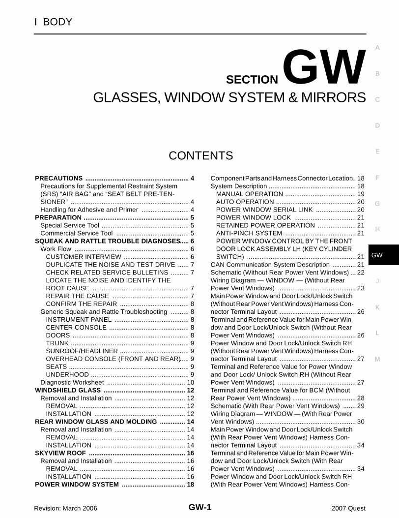
WIWA1777E

GW-26
POWER WINDOW SYSTEM
Revision: March 2006 2007 Quest
Main Power Window and Door Lock/Unlock Switch (Without Rear Power Vent Windows) Harness Connector Terminal Layout EIS0099T
Terminal and Reference Value for Main Power Window and Door Lock/Unlock Switch (Without Rear Power Vent Windows) EIS007HO
LIIA2454E
Terminal Wire Color Item ConditionVoltage (V)(Approx.)
1 W/R Battery power supply — Battery voltage
5 G/R Encoder power supplyIgnition switch ON or power win-dow timer operates
10
6 LFront door lock assembly LH (key cylinder switch) lock signal
Key position(Neutral → Locked)
5 → 0
7 RFront door lock assembly LH (key cylinder switch) unlock signal
Key position (Neutral → Unlocked)
5 → 0
8 G/RFront power window motor LH UP signal
Front power window motor LH is operated UP
Battery voltage
9 G/W Limit switch signal
Front door window LH is between fully-open and just before fully-closed position (ON)
0
Front door window LH is between just before fully-closed position and fully-closed position (OFF)
5
10 W/L RAP signal
Ignition switch ON Battery voltage
Within 45 second after ignition switch is turned to OFF
Battery voltage
More than 45 second after igni-tion switch is turned to OFF
0
Front door LH or RH open or power window timer operates
0
11 G/WFront power window motor LH DOWN signal
Front power window motor LH is operated DOWN
Battery voltage
12 Y Power window serial linkIgnition switch ON or power win-dow timer operates
PIIA2344J
POWER WINDOW SYSTEM
GW-27
C
D
E
F
G
H
J
K
L
M
A
B
GW
Revision: March 2006 2007 Quest
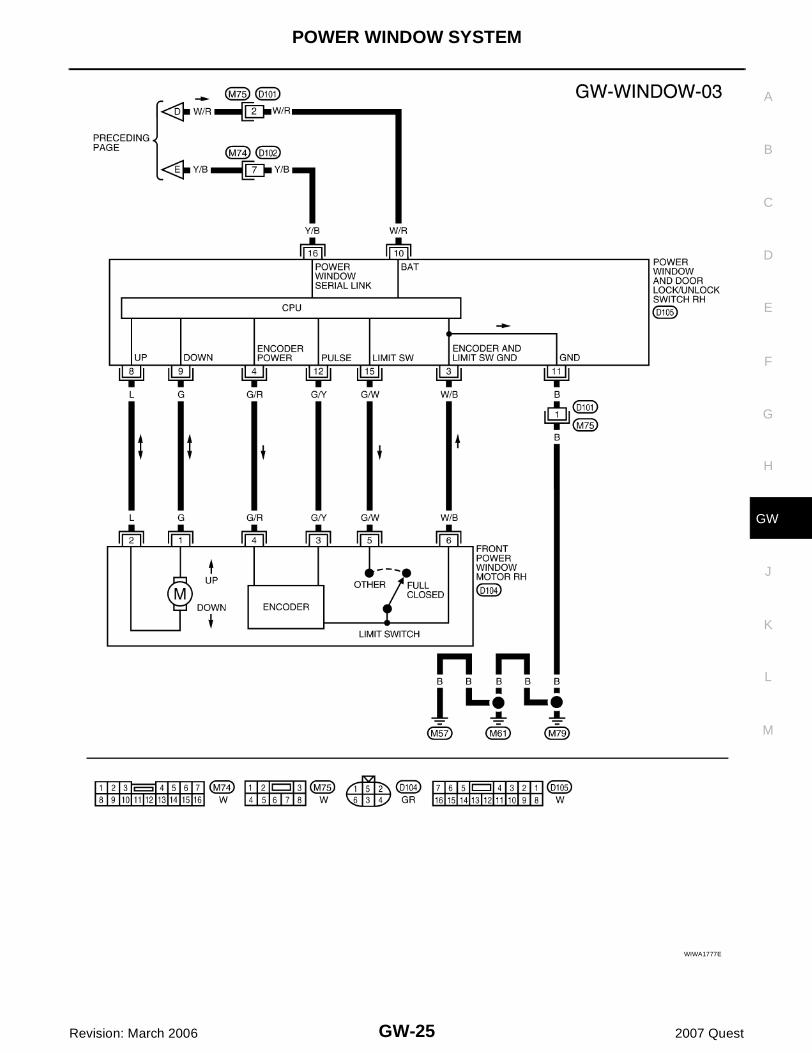
Power Window and Door Lock/Unlock Switch RH (Without Rear Power Vent Windows) Harness Connector Terminal Layout EIS0099U
Terminal and Reference Value for Power Window and Door Lock/ Unlock Switch RH (Without Rear Power Vent Windows) EIS007HP
13 G/Y Encoder pulse signalFront power window motor LH operates
14 W/B Limit switch and encoder ground — 0
15 B Ground — 0
Terminal Wire Color Item ConditionVoltage (V)(Approx.)
OCC3383D
LIIA2454E
TerminalWire Color
Item ConditionVoltage (V)(Approx.)
3 W/B Limit switch and encoder ground — 0
4 G/R Encoder power supplyIgnition switch ON or power window timer operates
10
8 LFront power window motor RHUP signal
Front power window motor RH is operated UP
Battery voltage
9 GFront power window motor RHDOWN signal
Front power window motor RH is operated DOWN
Battery voltage
10 W/R Battery power supply — Battery voltage
11 B Ground — 0
12 G/Y Encoder pulse signalFront power window motor RH operates
OCC3383D

GW-28
POWER WINDOW SYSTEM
Revision: March 2006 2007 Quest
Terminal and Reference Value for BCM (Without Rear Power Vent Windows) EIS007HQ
Refer to BCS-12, "Terminals and Reference Values for BCM" .
15 G/W Limit switch signal
Front door window RH is between fully-open and just before fully-closed position (ON)
0
Front door window RH is between just before fully-closed position and fully-closed position (OFF)
5
16 Y/B Power window serial linkIgnition switch ON or power window timer operates
TerminalWire Color
Item ConditionVoltage (V)(Approx.)
PIIA2344J

POWER WINDOW SYSTEM
GW-29
C
D
E
F
G
H
J
K
L
M
A
B
GW
Revision: March 2006 2007 Quest
Schematic (With Rear Power Vent Windows) EIS007HR
WIWA1778E

GW-30
POWER WINDOW SYSTEM
Revision: March 2006 2007 Quest
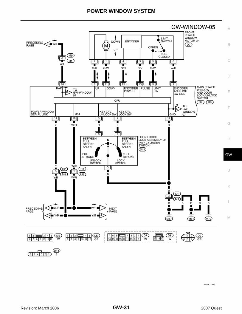
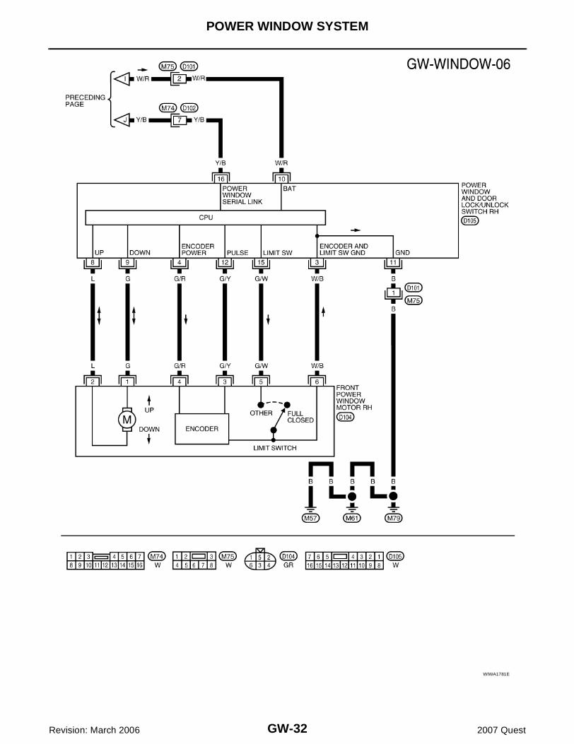
Wiring Diagram — WINDOW — (With Rear Power Vent Windows) EIS007HS
WIWA1779E
POWER WINDOW SYSTEM
GW-31
C
D
E
F
G
H
J
K
L
M
A
B
GW
Revision: March 2006 2007 Quest
WIWA1780E
GW-32
POWER WINDOW SYSTEM
Revision: March 2006 2007 Quest
WIWA1781E

POWER WINDOW SYSTEM
GW-33
C
D
E
F
G
H
J
K
L
M
A
B
GW
Revision: March 2006 2007 Quest
WIWA1782E

GW-34
POWER WINDOW SYSTEM
Revision: March 2006 2007 Quest
Main Power Window and Door Lock/Unlock Switch (With Rear Power Vent Win-dows) Harness Connector Terminal Layout EIS0099V
Terminal and Reference Value for Main Power Window and Door Lock/Unlock Switch (With Rear Power Vent Windows) EIS007HT
LIIA2455E
Terminal Wire Color Item ConditionVoltage (V)(Approx.)
1 R/YRear power vent window LH CLOSE signal
Rear LH switch in main power window and door lock/unlock switch is operated CLOSE
Battery voltage
2 W/B Limit switch and encoder ground — 0
3 R/BRear power vent window LH OPEN signal
Rear LH switch inmain power window and door lock/unlock switch is operatedOPEN
Battery voltage
4 LFront door lock assembly LH (key cylinder switch) lock signal
Key position(Neutral → Locked)
5 → 0
5 L/YRear power window vent OPEN signal
Rear RH switch in main power window and door lock/unlock switch is operatedOPEN
Battery voltage
6 RFront door lock assembly LH (key cylinder switch) unlock signal
Key position(Neutral → Unlocked)
5 → 0
7 RRear power window RHCLOSE signal
Rear RH switch in main power window and door lock/unlock switch is operated CLOSE
Battery voltage
8 G/RFront power window motor LH UP signal
Front power window motor LH is operated UP
Battery voltage
9 G/W Limit switch signal
Front door window LH is between fully-open and just before fully-closed position (ON)
0
Front door window LH is between just before fully-closed position and fully-closed position (OFF)
5
10 W/L RAP signal
Ignition switch ON Battery voltage
Within 45 seconds after ignition switch is turned to OFF
Battery voltage
More than 45 seconds after igni-tion switch is turned to OFF
0
Front door LH or RH open or power window timer operates
0
11 G/WFront power window motor LH DOWN signal
Front power window motor LH is operated DOWN
Battery voltage

POWER WINDOW SYSTEM
GW-35
C
D
E
F
G
H
J
K
L
M
A
B
GW
Revision: March 2006 2007 Quest
Power Window and Door Lock/Unlock Switch RH (With Rear Power Vent Win-dows) Harness Connector Terminal Layout EIS0099W
Terminal and Reference Value for Power Window and Door Lock/Unlock Switch RH (With Rear Power Vent Windows) EIS007HU
13 G/Y Encoder pulse signalFront power window motor LH operates
14 Y Power window serial linkIgnition switch ON or power win-dow timer operates
15 G/R Encoder power supplyIgnition switch ON or power win-dow timer operates
10
17 B Ground — 0
19 W/R Battery power supply — Battery voltage
Terminal Wire Color Item ConditionVoltage (V)(Approx.)
OCC3383D
PIIA2344J
LIIA2454E
Terminal Wire Color Item ConditionVoltage (V)(Approx.)
3 W/B Limit switch and encoder ground — 0
4 G/R Encoder power supplyIgnition switch ON or power win-dow timer operates
10
8 LFront power window motor RH UP signal
Front power window motor RH is operated UP
Battery voltage
9 GFront power window motor RH DOWN signal
Front power window motor RH is operated DOWN
Battery voltage
10 W/R Battery power supply — Battery voltage
11 B Ground — 0
12 G/Y Encoder pulse signalFront power window motor RH operates
OCC3383D

GW-36
POWER WINDOW SYSTEM
Revision: March 2006 2007 Quest
Terminal and Reference Value for BCM (With Rear Power Vent Windows) EIS007HV
Refer to BCS-12, "Terminals and Reference Values for BCM" .
15 G/W Limit switch signal
Front door window RH is between fully-open and just before fully-closed position (ON)
0
Front door window RH is between just before fully-closed position and fully-closed position (OFF)
5
16 Y/B Power window serial linkIgnition switch is ON or power window timer operating
Terminal Wire Color Item ConditionVoltage (V)(Approx.)
PIIA2344J
POWER WINDOW SYSTEM
GW-37
C
D
E
F
G
H
J
K
L
M
A
B
GW
Revision: March 2006 2007 Quest
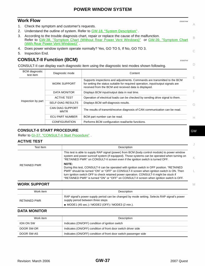
Work Flow EIS007HW
1. Check the symptom and customer's requests.2. Understand the outline of system. Refer to GW-18, "System Description" .3. According to the trouble diagnosis chart, repair or replace the cause of the malfunction.
Refer to GW-38, "Symptom Chart (Without Rear Power Vent Windows)" or GW-39, "Symptom Chart(With Rear Power Vent Windows)" .
4. Does power window system operate normally? Yes, GO TO 5, If No, GO TO 3.5. Inspection End.
CONSULT-II Function (BCM) EIS007HX
CONSULT-II can display each diagnostic item using the diagnostic test modes shown following.
CONSULT-II START PROCEDURERefer to GI-37, "CONSULT-II Start Procedure" .
ACTIVE TEST
WORK SUPPORT
DATA MONITOR
BCM diagnostic test item
Diagnostic mode Content
Inspection by part
WORK SUPPORTSupports inspections and adjustments. Commands are transmitted to the BCM for setting the status suitable for required operation, input/output signals are received from the BCM and received data is displayed.
DATA MONITOR Displays BCM input/output data in real time.
ACTIVE TEST Operation of electrical loads can be checked by sending drive signal to them.
SELF-DIAG RESULTS Displays BCM self-diagnosis results.
CAN DIAG SUPPORT MNTR
The results of transmit/receive diagnosis of CAN communication can be read.
ECU PART NUMBER BCM part number can be read.
CONFIGURATION Performs BCM configuration read/write functions.
Test Item Description
RETAINED PWR
This test is able to supply RAP signal (power) from BCM (body control module) to power window system and power sunroof system (if equipped). Those systems can be operated when turning on “RETAINED PWR” on CONSULT-II screen even if the ignition switch is turned OFF.
NOTE:During this test, CONSULT-II can be operated with ignition switch in OFF position. “RETAINED PWR” should be turned “ON” or “OFF” on CONSULT-II screen when ignition switch is ON. Then turn ignition switch OFF to check retained power operation. CONSULT-II might be stuck if “RETAINED PWR” is turned “ON” or “OFF” on CONSULT-II screen when ignition switch is OFF.
Work item Description
RETAINED PWRRAP signal’s power supply period can be changed by mode setting. Selects RAP signal’s power supply period between three steps
� MODE1 (45 sec.) / MODE2 (OFF) / MODE3 (2 min.).
Work item Description
IGN ON SW Indicates (ON/OFF) condition of ignition switch
DOOR SW-DR Indicates (ON/OFF) condition of front door switch driver side
DOOR SW-AS Indicates (ON/OFF) condition of front door switch passenger side

GW-38
POWER WINDOW SYSTEM
Revision: March 2006 2007 Quest
Symptom Chart (Without Rear Power Vent Windows) EIS007HY
� Check that other systems using the signal of the following systems operate normally.
Symptom Repair order Refer to page
None of the power windows can be operated using any switch
1. BCM power supply and ground circuit check BCS-15
2. Main power window and door lock/unlock supply and ground circuit check
GW-40
3. Power window serial link check GW-71
Front power window LH alone does not operate
1. Front power window motor LH circuit check GW-44
2. Replace main power window and door lock/unlock switch
EI-30
Front power window RH alone does not operate
1. Power window and door lock/unlock switch RH power and ground circuit check
GW-42
2. Power window serial link check GW-71
3. Front power window motor RH circuit check GW-44
4. Replace BCM BCS-25
Anti-pinch system does not operate normally (front LH)
1. Door window sliding part malfunction
� A foreign material adheres to window glass or glass run rubber.
� Glass run rubber wear or deformation.
� Sash is tilted too much, or not enough.
—
2. Limit switch adjusting GW-80
3. Limit switch circuit check LH GW-46
4. Encoder circuit check LH GW-56
Anti-pinch system does not operate normally (front RH)
1. Door window sliding part malfunction
� A foreign material adheres to window glass or glass run rubber.
� Glass run rubber wear or deformation.
� Sash is tilted too much, or not enough.
—
2. Limit switch adjusting GW-80
3. Limit switch circuit check RH GW-51
4. Encoder circuit check RH GW-61
Power window retained power operation does not operate properly
1. Check the retained power operation mode setting.
GW-37
2. Door switch check GW-66
3. Replace BCM. BCS-25
Front power windows do not operate by front door lock assembly LH (key cylinder switch)
1. Front door lock assembly LH (key cylinder switch) check
GW-67
2. Replace main power window and door lock/unlock switch
EI-30
Power window lock switch does not function 1. Power window lock switch circuit check GW-71

POWER WINDOW SYSTEM
GW-39
C
D
E
F
G
H
J
K
L
M
A
B
GW
Revision: March 2006 2007 Quest
Symptom Chart (With Rear Power Vent Windows) EIS007HZ
� Check that other systems using the signal of the following systems operate normally.
BCM Power Supply and Ground Circuit Check EIS007I0
Refer to BCS-15, "BCM Power Supply and Ground Circuit Check" .
Symptom Repair order Refer to page
None of the power windows can be operated using any switch
1. BCM power supply and ground circuit check BCS-15
2. Main power window and door lock/unlock supply and ground circuit check
GW-41
3. Power window serial link check GW-71
Front power window LH alone does not operate
1. Front power window motor LH circuit check GW-44
2. Replace main power window and door lock/unlock switch
EI-30
Front power window RH alone does not operate
1. Power window and door lock/unlock switch RH power and ground circuit check
GW-42
2. Power window serial link check GW-73
3. Front power window motor RH circuit check GW-44
4. Replace BCM BCS-25
Rear power vent window LH alone does not operate1. Rear power vent window motor LH circuit check
GW-75
Rear power vent window RH alone does not operate1. Rear power vent window motor RH circuit check
GW-76
Anti-pinch system does not operate normally (front LH)
1. Door window sliding part malfunction
� A foreign material adheres to window glass or glass run rubber.
� Glass run rubber wear or deformation.
� Sash is tilted too much, or not enough.
—
2. Limit switch adjusting GW-80
3. Limit switch circuit check LH GW-48
4. Encoder circuit check LH GW-56
Anti-pinch system does not operate normally (front RH)
1. Door window sliding part malfunction
� A foreign material adheres to window glass or glass run rubber.
� Glass run rubber wear or deformation.
� Sash is tilted too much, or not enough.
—
2. Limit switch adjusting GW-80
3. Limit switch circuit check RH GW-51
4. Encoder circuit check RH GW-61
Power window retained power operation does not operate properly
1. Check the retained power operation mode setting.
GW-37
2. Door switch check GW-66
3. Replace BCM. BCS-25
Front power windows do not operate by front door lock assembly LH (key cylinder switch)
1.Front door lock assembly LH (key cylinder switch) check
GW-69
2. Replace main power window and door lock/unlock switch
EI-30
Power window lock switch does not function 1. Power window lock switch circuit check GW-73

GW-40
POWER WINDOW SYSTEM
Revision: March 2006 2007 Quest
Main Power Window and Door Lock/Unlock Switch Power Supply Circuit Check (Without Rear Power Vent Windows) EIS007I1
1. CHECK POWER SUPPLY CIRCUIT
1. Turn ignition switch ON.2. Check voltage between main power window and door lock/
unlock switch connector D7 terminals 1, 10 and ground.
OK or NGOK >> GO TO 2.NG >> Repair or replace harness.
2. CHECK GROUND CIRCUIT
1. Turn ignition switch OFF.2. Disconnect main power window and door lock/unlock switch.3. Check continuity between main power window and door lock/
unlock switch connector D7 terminal 15 and ground.
OK or NGOK >> GO TO 3.NG >> Repair or replace harness.
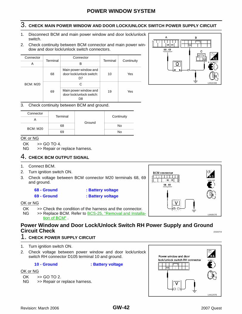
3. CHECK MAIN POWER WINDOW AND DOOR LOCK/UNLOCK SWITCH POWER SUPPLY CIRCUIT
1. Disconnect BCM and main power window and door lock/unlockswitch.
2. Check continuity between BCM connector and main power win-dow and door lock/unlock switch connector.
3. Check continuity between BCM and ground.
OK or NGOK >> GO TO 4.NG >> Repair or replace harness.
10 - Ground : Battery voltage
1 - Ground : Battery voltage
LIIA2312E
15 - Ground : Continuity should exist.
LIIA0604E
ConnectorTerminal
ConnectorTerminal Continuity
A B
BCM: M2068 Main power window and
door lock/unlock switch: D7
10 Yes
69 1 Yes
ConnectorTerminal
Ground
ContinuityA
BCM: M2068 No
69 No
LIIA2363E

POWER WINDOW SYSTEM
GW-41
C
D
E
F
G
H
J
K
L
M
A
B
GW
Revision: March 2006 2007 Quest
4. CHECK BCM OUTPUT SIGNAL
1. Connect BCM. 2. Turn ignition switch ON.3. Check voltage between BCM connector M20 terminals 68, 69
and ground.
OK or NGOK >> Check the condition of the harness and the connector.NG >> Replace BCM. Refer to BCS-25, "Removal and Installa-
tion of BCM" .
Main Power Window and Door Lock/Unlock Switch Power Supply Circuit Check (With Rear Power Vent Windows) EIS007I2
1. CHECK POWER SUPPLY CIRCUIT
1. Turn ignition switch ON.2. Check voltage between main power window and door lock/
unlock switch connector D7 terminal 10, D8 terminal 19 andground.
OK or NGOK >> GO TO 2.NG >> Repair or replace harness.
2. CHECK GROUND CIRCUIT
1. Turn ignition switch OFF.2. Disconnect main power window and door lock/unlock switch.3. Check continuity between main power window and door lock/
unlock switch connector D8 terminal 17 and ground.
OK or NGOK >> GO TO 3.NG >> Repair or replace harness.
68 - Ground : Battery voltage
69 - Ground : Battery voltage
LIIA0917E
10 - Ground : Battery voltage
19 - Ground : Battery voltage
LIIA2297E
17 - Ground : Continuity should exist.
LIIA0392E
GW-42
POWER WINDOW SYSTEM
Revision: March 2006 2007 Quest
3. CHECK MAIN POWER WINDOW AND DOOR LOCK/UNLOCK SWITCH POWER SUPPLY CIRCUIT
1. Disconnect BCM and main power window and door lock/unlockswitch.
2. Check continuity between BCM connector and main power win-dow and door lock/unlock switch connectors.
3. Check continuity between BCM and ground.
OK or NGOK >> GO TO 4.NG >> Repair or replace harness.
4. CHECK BCM OUTPUT SIGNAL
1. Connect BCM. 2. Turn ignition switch ON.3. Check voltage between BCM connector M20 terminals 68, 69
and ground.
OK or NGOK >> Check the condition of the harness and the connector.NG >> Replace BCM. Refer to BCS-25, "Removal and Installa-
tion of BCM" .
Power Window and Door Lock/Unlock Switch RH Power Supply and Ground Circuit Check EIS007I3
1. CHECK POWER SUPPLY CIRCUIT
1. Turn ignition switch ON.2. Check voltage between power window and door lock/unlock
switch RH connector D105 terminal 10 and ground.
OK or NGOK >> GO TO 2.NG >> Repair or replace harness.
ConnectorTerminal
ConnectorTerminal Continuity
A B
BCM: M20
68Main power window and door lock/unlock switch:
D710 Yes
69
C
19 YesMain power window and door lock/unlock switch:
D8
ConnectorTerminal
Ground
ContinuityA
BCM: M2068 No
69 No
LIIA2215E
68 - Ground : Battery voltage
69 - Ground : Battery voltage
LIIA0917E
10 - Ground : Battery voltage
LIIA1257E
POWER WINDOW SYSTEM
GW-43
C
D
E
F
G
H
J
K
L
M
A
B
GW
Revision: March 2006 2007 Quest
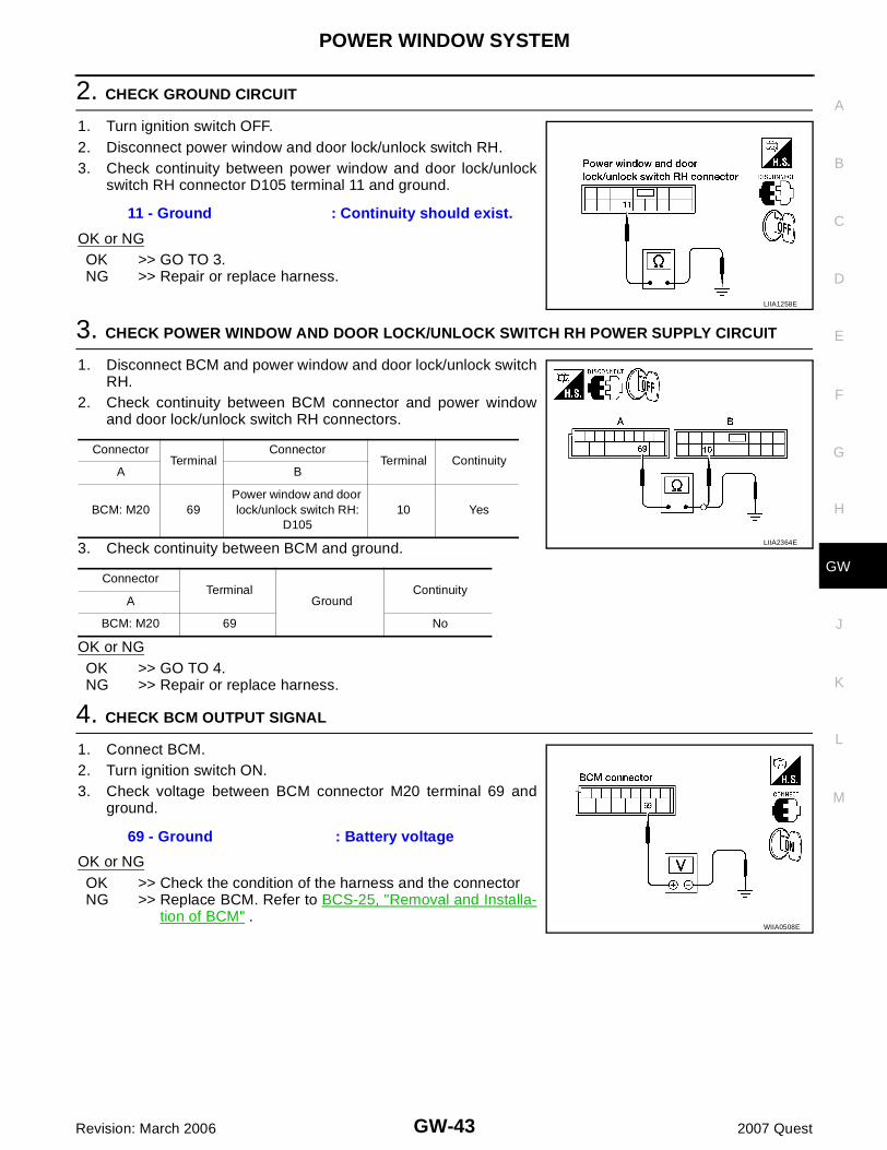
2. CHECK GROUND CIRCUIT
1. Turn ignition switch OFF.2. Disconnect power window and door lock/unlock switch RH.3. Check continuity between power window and door lock/unlock
switch RH connector D105 terminal 11 and ground.
OK or NGOK >> GO TO 3.NG >> Repair or replace harness.
3. CHECK POWER WINDOW AND DOOR LOCK/UNLOCK SWITCH RH POWER SUPPLY CIRCUIT
1. Disconnect BCM and power window and door lock/unlock switchRH.
2. Check continuity between BCM connector and power windowand door lock/unlock switch RH connectors.
3. Check continuity between BCM and ground.
OK or NGOK >> GO TO 4.NG >> Repair or replace harness.
4. CHECK BCM OUTPUT SIGNAL
1. Connect BCM.2. Turn ignition switch ON.3. Check voltage between BCM connector M20 terminal 69 and
ground.
OK or NGOK >> Check the condition of the harness and the connectorNG >> Replace BCM. Refer to BCS-25, "Removal and Installa-
tion of BCM" .
11 - Ground : Continuity should exist.
LIIA1258E
ConnectorTerminal
ConnectorTerminal Continuity
A B
BCM: M20 69Power window and door lock/unlock switch RH:
D10510 Yes
ConnectorTerminal
GroundContinuity
A
BCM: M20 69 No
LIIA2364E
69 - Ground : Battery voltage
WIIA0508E

GW-44
POWER WINDOW SYSTEM
Revision: March 2006 2007 Quest
Front Power Window Motor LH Circuit Check EIS007I4
1. CHECK MAIN POWER WINDOW AND DOOR LOCK/UNLOCK SWITCH OUTPUT SIGNAL
1. Turn ignition switch ON.2. Check voltage between main power window and door lock/
unlock switch connector D7 terminals 8, 11 and ground.
OK or NGOK >> GO TO 2.NG >> Replace main power window and door lock/unlock switch. Refer to EI-30, "FRONT DOOR" .
2. CHECK POWER WINDOW MOTOR CIRCUIT
1. Turn ignition switch OFF.2. Disconnect main power window and door lock/unlock switch and
front power window motor LH.3. Check continuity between main power window and door lock/
unlock switch connector D7 terminals 8, 11 and front power win-dow motor LH connector D9 terminals 1, 2.
OK or NGOK >> Replace front power window motor LH. Refer to GW-77,
"Removal and Installation" .NG >> Repair or replace harness.
Front Power Window Motor RH Circuit Check (Without Rear Power Vent Win-dows) EIS007I5
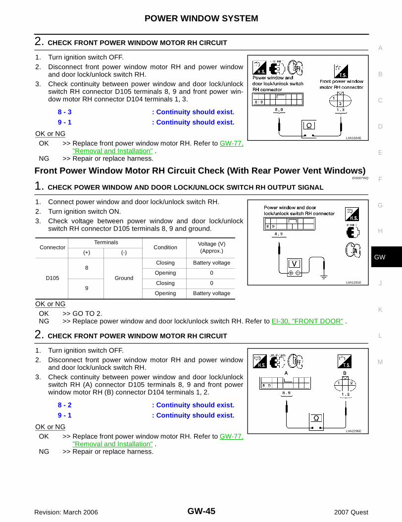
1. CHECK POWER WINDOW AND DOOR LOCK/UNLOCK SWITCH RH OUTPUT SIGNAL
1. Connect power window and door lock/unlock switch RH.2. Turn ignition switch ON.3. Check voltage between power window and door lock/unlock
switch RH connector D105 terminals 8, 9 and ground.
OK or NGOK >> GO TO 2.NG >> Replace power window and door lock/unlock switch RH. Refer to EI-30, "FRONT DOOR" .
ConnectorTerminals
ConditionVoltage (V)(Approx.)(+) (-)
D7
8
Ground
Closing Battery voltage
Opening 0
11Closing 0
Opening Battery voltage LIIA0317E
8 - 2 : Continuity should exist.
11 - 1 : Continuity should exist.
LIIA1260E
ConnectorTerminals
ConditionVoltage (V)(Approx.)(+) (-)
D105
8
Ground
Closing Battery voltage
Opening 0
9Closing 0
Opening Battery voltage
LIIA1261E
POWER WINDOW SYSTEM
GW-45
C
D
E
F
G
H
J
K
L
M
A
B
GW
Revision: March 2006 2007 Quest
2. CHECK FRONT POWER WINDOW MOTOR RH CIRCUIT
1. Turn ignition switch OFF.2. Disconnect front power window motor RH and power window
and door lock/unlock switch RH.3. Check continuity between power window and door lock/unlock
switch RH connector D105 terminals 8, 9 and front power win-dow motor RH connector D104 terminals 1, 3.
OK or NGOK >> Replace front power window motor RH. Refer to GW-77,
"Removal and Installation" .NG >> Repair or replace harness.
Front Power Window Motor RH Circuit Check (With Rear Power Vent Windows)EIS007WQ
1. CHECK POWER WINDOW AND DOOR LOCK/UNLOCK SWITCH RH OUTPUT SIGNAL
1. Connect power window and door lock/unlock switch RH.2. Turn ignition switch ON.3. Check voltage between power window and door lock/unlock
switch RH connector D105 terminals 8, 9 and ground.
OK or NGOK >> GO TO 2.NG >> Replace power window and door lock/unlock switch RH. Refer to EI-30, "FRONT DOOR" .
2. CHECK FRONT POWER WINDOW MOTOR RH CIRCUIT
1. Turn ignition switch OFF.2. Disconnect front power window motor RH and power window
and door lock/unlock switch RH.3. Check continuity between power window and door lock/unlock
switch RH (A) connector D105 terminals 8, 9 and front powerwindow motor RH (B) connector D104 terminals 1, 2.
OK or NGOK >> Replace front power window motor RH. Refer to GW-77,
"Removal and Installation" .NG >> Repair or replace harness.
8 - 3 : Continuity should exist.
9 - 1 : Continuity should exist.
LIIA1664E
ConnectorTerminals
ConditionVoltage (V)(Approx.)(+) (-)
D105
8
Ground
Closing Battery voltage
Opening 0
9Closing 0
Opening Battery voltage
LIIA1261E
8 - 2 : Continuity should exist.
9 - 1 : Continuity should exist.
LIIA2296E
GW-46
POWER WINDOW SYSTEM
Revision: March 2006 2007 Quest
Limit Switch Circuit Check Front LH (Without Rear Power Vent Windows) EIS007I6
1. CHECK MAIN POWER WINDOW AND DOOR LOCK/UNLOCK SWITCH LIMIT SIGNAL
1. Turn ignition switch ON.2. Check voltage between main power window and door lock/
unlock switch connector D7 terminal 9 and ground.
OK or NGOK >> Limit switch circuit is OK.NG >> GO TO 2.
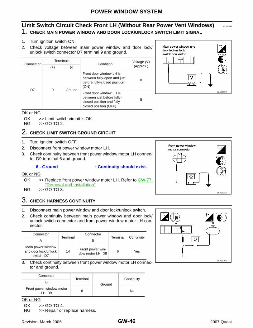
2. CHECK LIMIT SWITCH GROUND CIRCUIT
1. Turn ignition switch OFF.2. Disconnect front power window motor LH.3. Check continuity between front power window motor LH connec-
tor D9 terminal 6 and ground.
OK or NGOK >> Replace front power window motor LH. Refer to GW-77,
"Removal and Installation" .NG >> GO TO 3.
3. CHECK HARNESS CONTINUITY
1. Disconnect main power window and door lock/unlock switch.2. Check continuity between main power window and door lock/
unlock switch connector and front power window motor LH con-nector.
3. Check continuity between front power window motor LH connec-tor and ground.
OK or NGOK >> GO TO 4.NG >> Repair or replace harness.
ConnectorTerminals
Condition Voltage (V)(Approx.)(+) (-)
D7 9 Ground
Front door window LH is between fully-open and just before fully-closed position (ON)
0
Front door window LH is between just before fully-closed position and fully-closed position (OFF)
5
LIIA0339E
6 - Ground : Continuity should exist.
LIIA0923E
ConnectorTerminal
ConnectorTerminal Continuity
A B
Main power window and door lock/unlock
switch: D714
Front power win-dow motor LH: D9
6 Yes
ConnectorTerminal
Ground
ContinuityB
Front power window motor LH: D9
6 No
LIIA2276E

POWER WINDOW SYSTEM
GW-47
C
D
E
F
G
H
J
K
L
M
A
B
GW
Revision: March 2006 2007 Quest
4. CHECK HARNESS CONTINUITY
1. Check continuity between main power window and door lock/unlock switch connector and front power window motor LH con-nector.
2. Check continuity between front power window motor LH connec-tor and ground.
OK or NGOK >> GO TO 5.NG >> Repair or replace harness.
5. CHECK LIMIT SWITCH GROUND
Check continuity between main power window and door lock/unlockswitch connector and ground.
OK or NGOK >> GO TO 7.NG >> GO TO 6.
6. CHECK MAIN POWER WINDOW AND DOOR LOCK/UNLOCK SWITCH GROUND CIRCUIT
Check continuity between main power window and door lock/unlockswitch connector D7 terminal 15 and ground.
OK or NGOK >> Replace main power window and door lock/unlock
switch. Refer to EI-30, "FRONT DOOR" .NG >> Repair or replace harness.
ConnectorTerminal
ConnectorTerminal Continuity
A B
Main power window and door lock/unlock
switch: D79
Front power window motor
LH: D95 Yes
ConnectorTerminal
Ground
ContinuityB
Front power window motor LH: D9
5 No
LIIA2277E
Connector Terminal
Ground
Continuity
Main power window door lock/unlock switch: D7
14 Yes
LIIA2278E
15 - Ground : Continuity should exist.
LIIA0604E
GW-48
POWER WINDOW SYSTEM
Revision: March 2006 2007 Quest
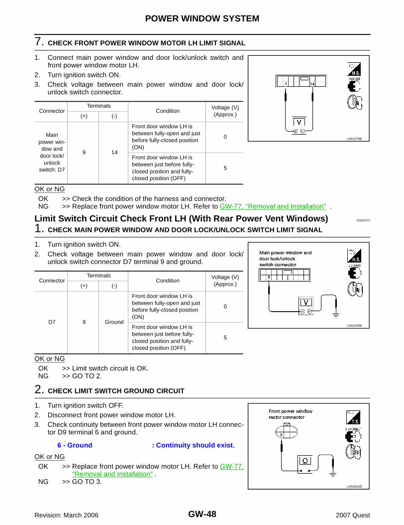
7. CHECK FRONT POWER WINDOW MOTOR LH LIMIT SIGNAL
1. Connect main power window and door lock/unlock switch andfront power window motor LH.
2. Turn ignition switch ON.3. Check voltage between main power window and door lock/
unlock switch connector.
OK or NGOK >> Check the condition of the harness and connector.NG >> Replace front power window motor LH. Refer to GW-77, "Removal and Installation" .
Limit Switch Circuit Check Front LH (With Rear Power Vent Windows) EIS007I7
1. CHECK MAIN POWER WINDOW AND DOOR LOCK/UNLOCK SWITCH LIMIT SIGNAL
1. Turn ignition switch ON.2. Check voltage between main power window and door lock/
unlock switch connector D7 terminal 9 and ground.
OK or NGOK >> Limit switch circuit is OK.NG >> GO TO 2.
2. CHECK LIMIT SWITCH GROUND CIRCUIT
1. Turn ignition switch OFF.2. Disconnect front power window motor LH.3. Check continuity between front power window motor LH connec-
tor D9 terminal 6 and ground.
OK or NGOK >> Replace front power window motor LH. Refer to GW-77,
"Removal and Installation" .NG >> GO TO 3.
ConnectorTerminals
Condition Voltage (V)(Approx.)(+) (-)
Main power win-dow and
door lock/unlock
switch: D7
9 14
Front door window LH is between fully-open and just before fully-closed position (ON)
0
Front door window LH is between just before fully-closed position and fully-closed position (OFF)
5
LIIA2279E
ConnectorTerminals
Condition Voltage (V)(Approx.)(+) (-)
D7 9 Ground
Front door window LH is between fully-open and just before fully-closed position (ON)
0
Front door window LH is between just before fully-closed position and fully-closed position (OFF)
5
LIIA0339E
6 - Ground : Continuity should exist.
LIIA0923E

POWER WINDOW SYSTEM
GW-49
C
D
E
F
G
H
J
K
L
M
A
B
GW
Revision: March 2006 2007 Quest
3. CHECK HARNESS CONTINUITY
1. Disconnect main power window and door lock/unlock switch.2. Check continuity between main power window and door lock/
unlock switch connector and front power window motor LH con-nector.
3. Check continuity between front power window motor LH connec-tor and ground.
OK or NGOK >> GO TO 4.NG >> Repair or replace harness.
4. CHECK HARNESS CONTINUITY
1. Check continuity between main power window and door lock/unlock switch connector and front power window motor LH con-nector.
2. Check continuity between front power window motor LH connec-tor and ground.
OK or NGOK >> GO TO 5.NG >> Repair or replace harness.
ConnectorTerminal
ConnectorTerminal Continuity
A B
Main power window and door lock/unlock
switch: D72
Front power win-dow motor LH: D9
6 Yes
ConnectorTerminal
Ground
ContinuityB
Front power window motor LH: D9
6 No
LIIA2222E
ConnectorTerminal
ConnectorTerminal Continuity
A B
Main power window and door lock/unlock
switch: D79
Front power window motor
LH: D95 Yes
ConnectorTerminal
Ground
ContinuityB
Front power window motor LH: D9
5 No
LIIA2277E

GW-50
POWER WINDOW SYSTEM
Revision: March 2006 2007 Quest
5. CHECK LIMIT SWITCH GROUND
Check continuity between main power window and door lock/unlockswitch connector and ground.
OK or NGOK >> GO TO 7.NG >> GO TO 6.
6. CHECK MAIN POWER WINDOW AND DOOR LOCK/UNLOCK SWITCH GROUND CIRCUIT
Check continuity between main power window and door lock/unlockswitch connector D8 terminal 17 and ground.
OK or NGOK >> Replace main power window and door lock/unlock
switch. Refer to EI-30, "FRONT DOOR" .NG >> Repair or replace harness.
7. CHECK FRONT POWER WINDOW MOTOR LH LIMIT SIGNAL
1. Connect main power window and door lock/unlock switch andfront power window motor LH.
2. Turn ignition switch ON.3. Check voltage between main power window and door lock/
unlock switch connector.
OK or NGOK >> Check the condition of the harness and connector.NG >> Replace front power window motor LH. Refer to GW-77, "Removal and Installation" .
Connector Terminal
Ground
Continuity
Main power window door lock/unlock switch: D7
2 Yes
LIIA2224E
17 - Ground : Continuity should exist.
LIIA1253E
ConnectorTerminals
Condition Voltage (V)(Approx.)(+) (-)
Main power win-dow and
door lock/unlock
switch: D7
9 2
Front door window LH is between fully-open and just before fully-closed position (ON)
0
Front door window LH is between just before fully-closed position and fully-closed position (OFF)
5
LIIA2225E

POWER WINDOW SYSTEM
GW-51
C
D
E
F
G
H
J
K
L
M
A
B
GW
Revision: March 2006 2007 Quest
Limit Switch Circuit Check Front RH (Without Rear Power Vent Windows) EIS007I8
1. CHECK POWER WINDOW AND DOOR LOCK/UNLOCK SWITCH RH LIMIT SIGNAL
1. Turn ignition switch ON.2. Check voltage between power window motor RH connector
D105 terminal 15 and ground.
OK or NGOK >> Limit switch circuit is OK.NG >> GO TO 2.
2. CHECK LIMIT SWITCH GROUND CIRCUIT
1. Turn ignition switch OFF.2. Disconnect front power window motor RH.3. Check continuity between front power window motor RH con-
nector D104 terminal 4 and ground.
OK or NGOK >> Replace front power window motor RH. Refer to GW-77,
"Removal and Installation" .NG >> GO TO 3.
3. CHECK HARNESS CONTINUITY
1. Disconnect power window and door lock/unlock switch RH.2. Check continuity between power window and door lock/unlock
switch RH connector and front power window motor RH connec-tor.
3. Check continuity between front power window motor RH con-nector and ground.
OK or NGOK >> GO TO 4.NG >> Repair or replace harness.
ConnectorTerminals
Condition Voltage (V)(Approx.)(+) (-)
D105 15 Ground
Front door window RH is between fully-open and just before fully-closed position (ON)
0
Front door window RH is between just before fully-closed position and fully-closed position (OFF)
5
LIIA1263E
4 - Ground : Continuity should exist.
LIIA2280E
ConnectorTerminal
ConnectorTerminal Continuity
A B
Power window and door lock/unlock switch RH: D105
3Front power win-dow motor RH:
D1044 Yes
ConnectorTerminal
Ground
ContinuityB
Front power window motor RH: D104
4 No
LIIA2281E

GW-52
POWER WINDOW SYSTEM
Revision: March 2006 2007 Quest
4. CHECK HARNESS CONTINUITY
1. Check continuity between power window and door lock/unlockswitch RH connector and front power window motor RH connec-tor.
2. Check continuity between front power window motor RH con-nector and ground.
OK or NGOK >> GO TO 5.NG >> Repair or replace harness.
5. CHECK LIMIT SWITCH GROUND
Check continuity between power window and door lock/unlockswitch RH connector and ground.
OK or NGOK >> GO TO 7.NG >> GO TO 6.
6. CHECK POWER WINDOW AND DOOR LOCK/UNLOCK SWITCH RH GROUND CIRCUIT
Check continuity between power window and door lock/unlockswitch RH connector D105 terminal 11 and ground.
OK or NGOK >> Replace power window and door lock/unlock switch RH.
Refer to EI-30, "FRONT DOOR" .NG >> Repair or replace harness.
ConnectorTerminal
ConnectorTerminal Continuity
A B
Power window and door lock/unlock switch RH: D105
15Front power
window motor RH: D104
2 Yes
ConnectorTerminal
Ground
ContinuityB
Front power window motor RH: D104
2 No
LIIA2282E
Connector Terminal
Ground
Continuity
Power window door lock/unlock switch RH: D105
3 Yes
LIIA2283E
11 - Ground : Continuity should exist.
LIIA1258E

POWER WINDOW SYSTEM
GW-53
C
D
E
F
G
H
J
K
L
M
A
B
GW
Revision: March 2006 2007 Quest
7. CHECK FRONT POWER WINDOW MOTOR RH LIMIT SIGNAL
1. Connect power window and door lock/unlock switch RH andfront power window motor RH.
2. Turn ignition switch ON.3. Check voltage between power window and door lock/unlock
switch RH connector.
OK or NGOK >> Check the condition of the harness and connector.NG >> Replace front power window motor RH. Refer to GW-77, "Removal and Installation" .
Limit Switch Circuit Check Front RH (With Rear Power Vent Windows) EIS007WR
1. CHECK POWER WINDOW AND DOOR LOCK/UNLOCK SWITCH RH LIMIT SIGNAL
1. Turn ignition switch ON.2. Check voltage between power window motor RH connector
D105 terminal 15 and ground.
OK or NGOK >> Limit switch circuit is OK.NG >> GO TO 2.
2. CHECK LIMIT SWITCH GROUND CIRCUIT
1. Turn ignition switch OFF.2. Disconnect front power window motor RH.3. Check continuity between front power window motor RH con-
nector D104 terminal 6 and ground.
OK or NGOK >> Replace front power window motor RH. Refer to GW-77,
"Removal and Installation" .NG >> GO TO 3.
ConnectorTerminals
Condition Voltage (V)(Approx.)(+) (-)
Power window
and door lock/
unlock switch RH:
D105
15 3
Front door window RH is between fully-open and just before fully-closed position (ON)
0
Front door window RH is between just before fully-closed position and fully-closed position (OFF)
5
LIIA2284E
ConnectorTerminals
Condition Voltage (V)(Approx.)(+) (-)
D105 15 Ground
Front door window RH is between fully-open and just before fully-closed position (ON)
0
Front door window RH is between just before fully-closed position and fully-closed position (OFF)
5
LIIA1263E
6 - Ground : Continuity should exist.
LIIA0923E
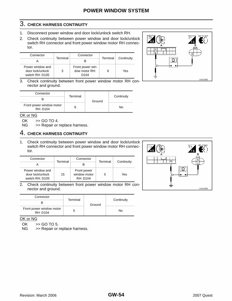
GW-54
POWER WINDOW SYSTEM
Revision: March 2006 2007 Quest
3. CHECK HARNESS CONTINUITY
1. Disconnect power window and door lock/unlock switch RH.2. Check continuity between power window and door lock/unlock
switch RH connector and front power window motor RH connec-tor.
3. Check continuity between front power window motor RH con-nector and ground.
OK or NGOK >> GO TO 4.NG >> Repair or replace harness.
4. CHECK HARNESS CONTINUITY
1. Check continuity between power window and door lock/unlockswitch RH connector and front power window motor RH connec-tor.
2. Check continuity between front power window motor RH con-nector and ground.
OK or NGOK >> GO TO 5.NG >> Repair or replace harness.
ConnectorTerminal
ConnectorTerminal Continuity
A B
Power window and door lock/unlock switch RH: D105
3Front power win-dow motor RH:
D1046 Yes
ConnectorTerminal
Ground
ContinuityB
Front power window motor RH: D104
6 No
LIIA2285E
ConnectorTerminal
ConnectorTerminal Continuity
A B
Power window and door lock/unlock switch RH: D105
15Front power
window motor RH: D104
5 Yes
ConnectorTerminal
Ground
ContinuityB
Front power window motor RH: D104
5 No
LIIA2286E

POWER WINDOW SYSTEM
GW-55
C
D
E
F
G
H
J
K
L
M
A
B
GW
Revision: March 2006 2007 Quest
5. CHECK LIMIT SWITCH GROUND
Check continuity between power window and door lock/unlockswitch RH connector and ground.
OK or NGOK >> GO TO 7.NG >> GO TO 6.
6. CHECK POWER WINDOW AND DOOR LOCK/UNLOCK SWITCH RH GROUND CIRCUIT
Check continuity between power window and door lock/unlockswitch RH connector D105 terminal 11 and ground.
OK or NGOK >> Replace power window and door lock/unlock switch RH.
Refer to EI-30, "FRONT DOOR" .NG >> Repair or replace harness.
7. CHECK FRONT POWER WINDOW MOTOR RH LIMIT SIGNAL
1. Connect power window and door lock/unlock switch RH andfront power window motor RH.
2. Turn ignition switch ON.3. Check voltage between power window and door lock/unlock
switch RH connector.
OK or NGOK >> Check the condition of the harness and connector.NG >> Replace front power window motor RH. Refer to GW-77, "Removal and Installation" .
Connector Terminal
Ground
Continuity
Power window door lock/unlock switch RH: D105
3 Yes
LIIA2283E
11 - Ground : Continuity should exist.
LIIA1258E
ConnectorTerminals
Condition Voltage (V)(Approx.)(+) (-)
Power window
and door lock/
unlock switch RH:
D105
15 3
Front door window RH is between fully-open and just before fully-closed position (ON)
0
Front door window RH is between just before fully-closed position and fully-closed position (OFF)
5
LIIA2284E

GW-56
POWER WINDOW SYSTEM
Revision: March 2006 2007 Quest
Encoder Circuit Check Front LH (Without Rear Power Vent Windows) EIS007I9
1. CHECK FRONT POWER WINDOW MOTOR LH POWER SUPPLY
1. Turn ignition switch OFF.2. Disconnect front power window motor LH.3. Turn ignition switch ON.4. Check voltage between front power window motor LH connector
D9 terminal 4 and ground.
OK or NGOK >> GO TO 3.NG >> GO TO 2.
2. CHECK HARNESS CONTINUITY
1. Turn ignition switch OFF.2. Disconnect main power window and door lock/unlock switch.3. Check continuity between front power window motor LH connec-
tor and main power window and door lock/unlock switch connec-tor.
4. Check continuity between front power window motor LH connector and ground.
OK or NGOK >> Replace main power window and door lock/unlock switch. Refer to EI-30, "FRONT DOOR" .NG >> Repair or replace harness.
3. CHECK ENCODER GROUND
1. Turn ignition switch OFF.2. Disconnect front power window motor LH.3. Check continuity between front power window motor LH connec-
tor D9 terminal 6 and ground.
OK or NGOK >> GO TO 5.NG >> GO TO 4.
4 - Ground : Approx. 10V
LIIA2299E
ConnectorTerminal
ConnectorTerminal Continuity
A B
Main power window and door lock/unlock
switch: D75
Front power win-dow motor LH:
D94 Yes
ConnectorTerminal
Ground
ContinuityB
Front power window motor LH: D9
4 No
LIIA2287E
6 - Ground : Continuity should exist.
LIIA0923E

POWER WINDOW SYSTEM
GW-57
C
D
E
F
G
H
J
K
L
M
A
B
GW
Revision: March 2006 2007 Quest
4. CHECK ENCODER GROUND CIRCUIT
1. Disconnect main power window and door lock/unlock switch.2. Check continuity between front power window motor LH connec-
tor D9 terminal 6 and main power window and door lock/unlockswitch connector D7 terminal 14.
OK or NGOK >> Replace main power window and door lock/unlock
switch. Refer to EI-30, "FRONT DOOR" .NG >> Repair or replace harness.
5. CHECK ENCODER SIGNAL
1. Connect front power window motor LH.2. Turn ignition switch ON.3. Check the signal between main power window and door lock/
unlock switch connector and ground with oscilloscope.
OK or NGOK >> Replace main power window and door lock/unlock switch. Refer to EI-30, "FRONT DOOR" .NG >> GO TO 6.
6 - 14 : Continuity should exist.
LIIA1158E
Connec-tor
TerminalsCondition Signal
(+) (-)
D7 13 Ground OpeningLIIA0364E
OCC3383D

GW-58
POWER WINDOW SYSTEM
Revision: March 2006 2007 Quest
6. CHECK ENCODER CIRCUIT
1. Turn ignition switch OFF.2. Disconnect front power window motor LH and main power win-
dow and door lock/unlock switch.3. Check continuity between front power window motor LH connec-
tor and main power window and door lock/unlock switch connec-tor.
4. Check continuity between front power window motor LH connector and ground.
OK or NGOK >> Replace front power window motor LH. Refer to GW-77, "Removal and Installation" .NG >> Repair or replace harness.
Encoder Circuit Check Front LH (With Rear Power Vent Windows) EIS007IA
1. CHECK FRONT POWER WINDOW MOTOR LH POWER SUPPLY
1. Turn ignition switch OFF.2. Disconnect front power window motor LH.3. Turn ignition switch ON.4. Check voltage between front power window motor LH connector
D9 terminal 4 and ground.
OK or NGOK >> GO TO 3.NG >> GO TO 2.
ConnectorTerminal
ConnectorTerminal Continuity
A B
Main power win-dow and door lock/unlock switch: D7
13Front power win-dow motor LH:
D93 Yes
ConnectorTerminal
Ground
ContinuityB
Front power window motor LH: D9
3 No
LIIA2210E
4 - Ground : Approx. 10V
LIIA2299E

POWER WINDOW SYSTEM
GW-59
C
D
E
F
G
H
J
K
L
M
A
B
GW
Revision: March 2006 2007 Quest
2. CHECK HARNESS CONTINUITY
1. Turn ignition switch OFF.2. Disconnect main power window and door lock/unlock switch.3. Check continuity between front power window motor LH connec-
tor and main power window and door lock/unlock switch connec-tor.
4. Check continuity between front power window motor LH connector and ground.
OK or NGOK >> Replace main power window and door lock/unlock switch. Refer to EI-30, "FRONT DOOR" .NG >> Repair or replace harness.
3. CHECK ENCODER GROUND
1. Turn ignition switch OFF.2. Disconnect front power window motor LH.3. Check continuity between front power window motor LH connec-
tor D9 terminal 6 and ground.
OK or NGOK >> GO TO 5.NG >> GO TO 4.
4. CHECK ENCODER GROUND CIRCUIT
1. Disconnect main power window and door lock/unlock switch.2. Check continuity between front power window motor LH connec-
tor D9 terminal 6 and main power window and door lock/unlockswitch connector D7 terminal 2.
OK or NGOK >> Replace main power window and door lock/unlock
switch. Refer to EI-30, "FRONT DOOR" .NG >> Repair or replace harness.
ConnectorTerminal
ConnectorTerminal Continuity
A B
Main power window and door lock/unlock
switch: D715
Front power win-dow motor LH:
D94 Yes
ConnectorTerminal
Ground
ContinuityB
Front power window motor LH: D9
4 No
LIIA2289E
6 - Ground : Continuity should exist.
LIIA0923E
6 - 2 : Continuity should exist.
WIIA0511E

GW-60
POWER WINDOW SYSTEM
Revision: March 2006 2007 Quest
5. CHECK ENCODER SIGNAL
1. Connect front power window motor LH.2. Turn ignition switch ON.3. Check the signal between main power window and door lock/
unlock switch connector and ground with oscilloscope.
OK or NGOK >> Replace main power window and door lock/unlock switch. Refer to EI-30, "FRONT DOOR" .NG >> GO TO 6.
6. CHECK ENCODER CIRCUIT
1. Turn ignition switch OFF.2. Disconnect front power window motor LH and main power win-
dow and door lock/unlock switch.3. Check continuity between front power window motor LH connec-
tor and main power window and door lock/unlock switch connec-tor.
4. Check continuity between front power window motor LH connector and ground.
OK or NGOK >> Replace front power window motor LH. Refer to GW-77, "Removal and Installation" .NG >> Repair or replace harness.
Connec-tor
TerminalsCondition Signal
(+) (-)
D7 13 Ground OpeningLIIA0364E
OCC3383D
ConnectorTerminal
ConnectorTerminal Continuity
A B
Main power win-dow and door lock/unlock switch: D7
13Front power win-dow motor LH:
D93 Yes
ConnectorTerminal
Ground
ContinuityB
Front power window motor LH: D9
3 No
LIIA2210E

POWER WINDOW SYSTEM
GW-61
C
D
E
F
G
H
J
K
L
M
A
B
GW
Revision: March 2006 2007 Quest
Encoder Circuit Check Front RH (Without Rear Power Vent Windows) EIS007IB
1. CHECK FRONT POWER WINDOW MOTOR RH POWER SUPPLY
1. Turn ignition switch OFF.2. Disconnect front power window motor RH.3. Turn ignition switch ON.4. Check voltage between front power window motor RH connector
D104 terminal 6 and ground.
OK or NGOK >> GO TO 3.NG >> GO TO 2.
2. CHECK HARNESS CONTINUITY
1. Turn ignition switch OFF.2. Disconnect power window and door lock/unlock switch RH.3. Check continuity between front power window motor RH con-
nector and power window and door lock/unlock switch RH con-nector.
4. Check continuity between front power window motor LH connector and ground.
OK or NGOK >> Replace main power window and door lock/unlock switch. Refer to EI-30, "FRONT DOOR" .NG >> Repair or replace harness.
3. CHECK ENCODER GROUND
1. Turn ignition switch OFF.2. Check continuity between front power window motor RH con-
nector D104 terminal 4 and ground.
OK or NGOK >> GO TO 5.NG >> GO TO 4.
6 - Ground : Approx. 10V
LIIA2314E
ConnectorTerminal
ConnectorTerminal Continuity
A B
Power window and door lock/unlock switch RH: D105
4Front power win-dow motor RH:
D1046 Yes
ConnectorTerminal
Ground
ContinuityB
Front power window motor RH: D104
6 No
LIIA2291E
4 - Ground : Continuity should exist.
LIIA2280E

GW-62
POWER WINDOW SYSTEM
Revision: March 2006 2007 Quest
4. CHECK ENCODER GROUND CIRCUIT
1. Disconnect power window and door lock/unlock switch RH.2. Check continuity between power window and door lock/unlock
switch RH (A) connector D105 terminal 14 and front power win-dow motor RH (B) connector D104 terminal 6.
OK or NGOK >> Replace power window and door lock/unlock switch RH.
Refer to EI-30, "FRONT DOOR" .NG >> Repair or replace harness.
5. CHECK ENCODER SIGNAL
1. Connect front power window motor RH.2. Turn ignition switch ON.3. Check the signal between power window and door lock/unlock
switch RH connector and ground with oscilloscope.
OK or NGOK >> Replace power window and door lock/unlock switch RH. Refer to EI-30, "FRONT DOOR" .NG >> GO TO 6.
6 - 14 : Continuity should exist.
LIIA2292E
Connec-tor
TerminalsCondition Signal
(+) (-)
D105 12 Ground OpeningLIIA1267E
OCC3383D

POWER WINDOW SYSTEM
GW-63
C
D
E
F
G
H
J
K
L
M
A
B
GW
Revision: March 2006 2007 Quest
6. CHECK ENCODER CIRCUIT
1. Turn ignition switch OFF.2. Disconnect front power window motor RH and power window
and door lock/unlock switch RH.3. Check continuity between front power window motor RH con-
nector and power window and door lock/unlock switch RH con-nector.
4. Check continuity between front power window motor LH connector and ground.
OK or NGOK >> Replace front power window motor RH. Refer to GW-77, "Removal and Installation" .NG >> Repair or replace harness.
Encoder Circuit Check Front RH (With Rear Power Vent Windows) EIS007WS
1. CHECK FRONT POWER WINDOW MOTOR RH POWER SUPPLY
1. Turn ignition switch OFF.2. Disconnect front power window motor RH.3. Turn ignition switch ON.4. Check voltage between front power window motor RH connector
D104 terminal 4 and ground.
OK or NGOK >> GO TO 3.NG >> GO TO 2.
ConnectorTerminal
ConnectorTerminal Continuity
A B
Power window and door lock/unlock switch RH: D105
12Front power win-dow motor RH:
D1045 Yes
ConnectorTerminal
Ground
ContinuityB
Front power window motor RH: D104
5 No
LIIA2293E
4 - Ground : Approx. 10V
LIIA2290E

GW-64
POWER WINDOW SYSTEM
Revision: March 2006 2007 Quest
2. CHECK HARNESS CONTINUITY
1. Turn ignition switch OFF.2. Disconnect power window and door lock/unlock switch RH.3. Check continuity between front power window motor RH con-
nector and power window and door lock/unlock switch RH con-nector.
4. Check continuity between front power window motor LH connector and ground.
OK or NGOK >> Replace main power window and door lock/unlock switch. Refer to EI-30, "FRONT DOOR" .NG >> Repair or replace harness.
3. CHECK ENCODER GROUND
1. Turn ignition switch OFF.2. Disconnect front power window motor RH.3. Check continuity between front power window motor RH con-
nector D104 terminal 6 and ground.
OK or NGOK >> GO TO 5.NG >> GO TO 4.
4. CHECK ENCODER GROUND CIRCUIT
1. Disconnect power window and door lock/unlock switch RH.2. Check continuity between front power window motor RH con-
nector D104 terminal 6 and power window and door lock/unlockswitch RH connector D105 terminal 3.
OK or NGOK >> Replace power window and door lock/unlock switch RH.
Refer to EI-30, "FRONT DOOR" .NG >> Repair or replace harness.
ConnectorTerminal
ConnectorTerminal Continuity
A B
Power window and door lock/unlock switch RH: D105
4Front power win-dow motor RH:
D1044 Yes
ConnectorTerminal
Ground
ContinuityB
Front power window motor RH: D104
4 No
LIIA2294E
6 - Ground : Continuity should exist.
LIIA0923E
6 - 3 : Continuity should exist.
LIIA1264E
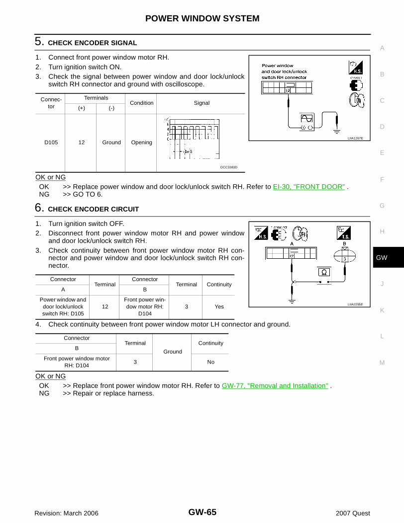
POWER WINDOW SYSTEM
GW-65
C
D
E
F
G
H
J
K
L
M
A
B
GW
Revision: March 2006 2007 Quest
5. CHECK ENCODER SIGNAL
1. Connect front power window motor RH.2. Turn ignition switch ON.3. Check the signal between power window and door lock/unlock
switch RH connector and ground with oscilloscope.
OK or NGOK >> Replace power window and door lock/unlock switch RH. Refer to EI-30, "FRONT DOOR" .NG >> GO TO 6.
6. CHECK ENCODER CIRCUIT
1. Turn ignition switch OFF.2. Disconnect front power window motor RH and power window
and door lock/unlock switch RH.3. Check continuity between front power window motor RH con-
nector and power window and door lock/unlock switch RH con-nector.
4. Check continuity between front power window motor LH connector and ground.
OK or NGOK >> Replace front power window motor RH. Refer to GW-77, "Removal and Installation" .NG >> Repair or replace harness.
Connec-tor
TerminalsCondition Signal
(+) (-)
D105 12 Ground OpeningLIIA1267E
OCC3383D
ConnectorTerminal
ConnectorTerminal Continuity
A B
Power window and door lock/unlock switch RH: D105
12Front power win-dow motor RH:
D1043 Yes
ConnectorTerminal
Ground
ContinuityB
Front power window motor RH: D104
3 No
LIIA2295E

GW-66
POWER WINDOW SYSTEM
Revision: March 2006 2007 Quest
Door Switch Check EIS007IC
1. CHECK FRONT DOOR SWITCH INPUT SIGNAL
With CONSULT-IICheck front door switches (“DOOR SW-DR” and “DOOR SW-AS”) in“DATA MONITOR” mode with CONSULT-II.
Without CONSULT-IICheck voltage between BCM connector and ground.
OK or NGOK >> Front door switch is OK.NG >> GO TO 2.
2. CHECK DOOR SWITCH CIRCUIT
1. Turn ignition switch OFF.2. Disconnect front door switch LH or RH and BCM.3. Check continuity between front door switch LH or RH and BCM.
4. Check continuity between front door switch LH or RH andground.
OK or NGOK >> GO TO 3.NG >> Repair or replace harness.
Monitor item Condition
DOOR SW-DROPEN: ON
CLOSE: OFF
DOOR SW-ASOPEN: ON
CLOSE: OFF
PIIA2464E
Item ConnectorTerminals
ConditionVoltage (V)(Approx.)(+) (-)
Front RH M18 12
Ground
OPEN 0
CLOSE Battery voltage
Front LH M19 47OPEN 0
CLOSE Battery voltage
WIIA0515E
ConnectorTerminal
ConnectorTerminal Continuity
A B
BCM: M18 12Front door switch
RH: B1081 Yes
BCM: M19 47Front door switch
LH: B81 Yes
ConnectorTerminal
Ground
ContinuityA
Front door switch LH: B8
1 No
Front door switch RH: B108
1 No
WIIA1126E

POWER WINDOW SYSTEM
GW-67
C
D
E
F
G
H
J
K
L
M
A
B
GW
Revision: March 2006 2007 Quest
3. CHECK DOOR SWITCH
Check continuity between each front door switch terminal 1 andbody ground part of front door switch.
OK or NGOK >> Further inspection is necessary. Refer to symptom
chart.NG >> Replace malfunctioning front door switch.
Front Door Lock Assembly LH (Key Cylinder Switch) Check (Without Rear Power Vent Windows) EIS007ID
1. CHECK DOOR KEY CYLINDER SWITCH INPUT SIGNAL
With CONSULT-II� Check front door lock assembly LH (key cylinder switch) (“KEY
CYL LK-SW”) in “DATA MONITOR” mode for “POWER DOORLOCK SYSTEM” with CONSULT-II. Refer to GW-37, "DATAMONITOR" .
� Check front door lock assembly LH (key cylinder switch) (“KEYCYL UN-SW”) in “DATA MONITOR” mode for “POWER DOORLOCK SYSTEM” with CONSULT-II. Refer to GW-37, "DATAMONITOR" .
Without CONSULT-IICheck voltage between main power window and door lock/unlockswitch connector and ground.
OK or NGOK >> Further inspection is necessary. Refer to symptom
chart.NG >> GO TO 2.
Terminal Door switch Continuity
1Body ground part
of front door switch
Pushed No
Released Yes
WIIA0782E
“KEY CYL LK-SW” should be “ON” when key inserted in door key cylinder is turned to lock.
LIIA0047E
“KEY CYL UN-SW” should be “ON” when key inserted in door key cylinder is turned to unlock.
LIIA0050E
ConnectorTerminals
Key position Voltage (V) (Approx.)(+) (-)
D7
7
Ground
Neutral/Unlock 5
Unlock 0
6Neutral/Lock 5
Lock 0
LIIA1161E

GW-68
POWER WINDOW SYSTEM
Revision: March 2006 2007 Quest
2. CHECK FRONT DOOR LOCK ASSEMBLY LH (KEY CYLINDER SWITCH) CIRCUIT
1. Turn ignition switch OFF.2. Disconnect main power window and door lock/unlock switch and
front door lock assembly LH (key cylinder switch).3. Check continuity between main power window and door lock/
unlock switch connector D7 terminals 6, 7 and front door lockassembly LH (key cylinder switch) connector D14 terminals 1, 6.
OK or NGOK >> GO TO 3.NG >> Repair or replace harness.
3. CHECK FRONT DOOR LOCK ASSEMBLY LH (KEY CYLINDER SWITCH) GROUND
Check continuity between front door lock assembly LH (key cylinderswitch) connector D14 terminal 5 and ground.
OK or NGOK >> GO TO 4.NG >> Repair or replace harness.
4. CHECK FRONT DOOR LOCK ASSEMBLY LH (KEY CYLINDER SWITCH)
Check continuity between front door lock assembly LH (key cylinderswitch) terminals 1, 6 and 5.
OK or NGOK >> Further inspection is necessary. Refer to symptom
chart.NG >> Replace front door lock assembly LH (key cylinder switch). Refer to BL-190, "Removal and Instal-
lation" .
7 - 6 : Continuity should exist.
6 - 1 : Continuity should exist.
LIIA1602E
5 - Ground : Continuity should exist.
LIIA1572E
Terminals Key position Continuity
6
5
Neutral/Lock No
Unlock Yes
1Neutral/Unlock No
Lock Yes
LIIA1573E

POWER WINDOW SYSTEM
GW-69
C
D
E
F
G
H
J
K
L
M
A
B
GW
Revision: March 2006 2007 Quest
Front Door Lock Assembly LH (Key Cylinder Switch) Check (With Rear Power Vent Windows) EIS007IE
1. CHECK DOOR KEY CYLINDER SWITCH INPUT SIGNAL
With CONSULT-II� Check front door lock assembly LH (key cylinder switch) (“KEY
CYL LK-SW”) in “DATA MONITOR” mode for “POWER DOORLOCK SYSTEM” with CONSULT-II. Refer to GW-37, "DATAMONITOR" .
� Check front door lock assembly LH (key cylinder switch) (“KEYCYL UN-SW”) in “DATA MONITOR” mode for “POWER DOORLOCK SYSTEM” with CONSULT-II. Refer to GW-37, "DATAMONITOR" .
Without CONSULT-IICheck voltage between main power window and door lock/unlockswitch connector and ground.
OK or NGOK >> Further inspection is necessary. Refer to symptom
chart.NG >> GO TO 2.
“KEY CYL LK-SW” should be “ON” when key inserted in door key cylinder is turned to lock.
LIIA0047E
“KEY CYL UN-SW” should be “ON” when key inserted in door key cylinder is turned to unlock.
LIIA0050E
ConnectorTerminals
Key position Voltage (V) (Approx.)(+) (-)
D7
6
Ground
Neutral/Lock 5
Lock 0
4Neutral/Unlock 5
Unlock 0
LIIA1269E

GW-70
POWER WINDOW SYSTEM
Revision: March 2006 2007 Quest
2. CHECK FRONT DOOR LOCK ASSEMBLY LH (KEY CYLINDER SWITCH) CIRCUIT
1. Turn ignition switch OFF.2. Disconnect main power window and door lock/unlock switch and
front door lock assembly LH (key cylinder switch).3. Check continuity between main power window and door lock/
unlock switch connector D7 terminals 4, 6 and front door lockassembly LH (key cylinder switch) connector D14 terminals 1, 6.
OK or NGOK >> GO TO 3.NG >> Repair or replace harness.
3. CHECK FRONT DOOR LOCK ASSEMBLY LH (KEY CYLINDER SWITCH) GROUND
Check continuity between front door lock assembly LH (key cylinderswitch) connector D14 terminal 5 and ground.
OK or NGOK >> GO TO 4.NG >> Repair or replace harness.
4. CHECK FRONT DOOR LOCK ASSEMBLY LH (KEY CYLINDER SWITCH)
Check continuity between front door lock assembly LH (key cylinderswitch) terminals 1, 6 and 5.
OK or NGOK >> Further inspection is necessary. Refer to symptom
chart.NG >> Replace front door lock assembly LH (key cylinder switch). Refer to BL-190, "Removal and Instal-
lation" .
6 - 6 : Continuity should exist.
4 - 1 : Continuity should exist.
LIIA1571E
5 - Ground : Continuity should exist.
LIIA1572E
Terminals Key position Continuity
6
5
Neutral/Lock No
Unlock Yes
1Neutral/Unlock No
Lock Yes
LIIA1573E

POWER WINDOW SYSTEM
GW-71
C
D
E
F
G
H
J
K
L
M
A
B
GW
Revision: March 2006 2007 Quest
Power Window Serial Link Check Front LH and RH (Without Rear Power Vent Windows) EIS007IF
1. CHECK BUS OUTPUT SIGNAL
With CONSULT-IICheck door lock and unlock switch (“LOCK SW DR/AS”, “UNLK SWDR/AS”) in DATA MONITOR mode for “MULTI REMOTE ENT” withCONSULT-II. Refer to BL-62, "Data Monitor" .� When door lock and unlock switch is turned to LOCK
� When door lock and unlock switch is turned to UNLOCK
Without CONSULT-II1. Remove key from ignition switch, and close front door LH and
RH.2. Check the signal between BCM connector and ground with
oscilloscope when door lock and unlock switch (front LH andfront RH) is turned to “LOCK” or “UNLOCK”.
3. Make sure signals which are shown in the figure below can bedetected during 10 seconds just after door lock and unlockswitch (front LH and front RH) is turned to “LOCK” or“UNLOCK”.
OK or NGOK >> GO TO 2.NG >> GO TO 3.
2. CHECK BCM BUS SIGNAL
Check power window serial link (“POWER WINDOW DOWN”) in“ACTIVE TEST” mode for "MULTI REMOTE ENT" with CONSULT-II.Refer to BL-62, "Active Test" .When “ACTIVE TEST” is executed, is the front power window LHand RH lowered?OK or NGOK >> Further inspection is necessary. Refer to symptom
chart.NG >> Replace BCM. Refer to BCS-25, "Removal and Installa-
tion of BCM" .
LOCK SW DR/AS : ON
UNLK SW DR/AS : ON
LIIA0172E
ConnectorTerminals
Signal(+) (-)
M18 22 Ground
LIIA0391E
PIIA1297E
PIIA3080E

GW-72
POWER WINDOW SYSTEM
Revision: March 2006 2007 Quest
3. CHECK POWER WINDOW SWITCH GROUND
1. Turn ignition switch OFF.2. Disconnect main power window and door lock/unlock switch and
power window and door lock/unlock switch RH.3. Check continuity between main power window and door lock/
unlock switch connector D7 terminal 15 and ground.
4. Check continuity between power window and door lock/unlockswitch RH connector D105 terminal 11 and ground.
OK or NGOK >> GO TO 4.NG >> Repair or replace harness.
4. CHECK POWER WINDOW SERIAL LINK CIRCUIT
1. Disconnect BCM.2. Check continuity between BCM connector M18 terminal 22 and
main power window and door lock/unlock switch connector D7terminal 12.
3. Check continuity between BCM connector M18 terminal 22 andpower window and door lock/unlock switch RH connector D105terminal 16.
OK or NGOK >> Replace main power window and door lock/unlock
switch or power window and door lock/unlock switchRH. Refer to EI-30, "Removal and Installation" .
NG >> Repair or replace harness.
15 - Ground : Continuity should exist.
LIIA0604E
11 - Ground : Continuity should exist.
LIIA1270E
22 - 12 : Continuity should exist.
LIIA0649E
22 - 16 : Continuity should exist.
LIIA1271E

POWER WINDOW SYSTEM
GW-73
C
D
E
F
G
H
J
K
L
M
A
B
GW
Revision: March 2006 2007 Quest
Power Window Serial Link Check Front LH and RH (With Rear Power Vent Win-dows) EIS007IG
1. CHECK BUS SIGNAL
With CONSULT-IICheck door lock and unlock switch (“LOCK SW DR/AS”, “UNLK SWDR/AS”) in DATA MONITOR mode for “MULTI REMOTE ENT” withCONSULT-II. Refer to BL-62, "Data Monitor" .� When door lock and unlock switch is turned to LOCK
� When door lock and unlock switch is turned to UNLOCK
Without CONSULT-II1. Remove key from ignition switch, and close front door LH and
RH.2. Check the signal between BCM connector and ground with
oscilloscope when door lock and unlock switch (front LH andfront RH) is turned to “LOCK” or “UNLOCK”.
3. Make sure signals which are shown in the figure below can bedetected during 10 seconds just after door lock and unlockswitch (front LH and front RH) is turned to “LOCK” or“UNLOCK”.
OK or NGOK >> GO TO 2.NG >> GO TO 3.
2. CHECK BCM BUS OUTPUT SIGNAL
Check power window serial link (“POWER WINDOW DOWN”) in“ACTIVE TEST” mode for "MULTI REMOTE ENT" with CONSULT-II.Refer to BL-62, "Active Test" .When “ACTIVE TEST” is executed, is the front power window LHand RH lowered?OK or NGOK >> Further inspection is necessary. Refer to symptom
chart.NG >> Replace BCM. Refer to BCS-25, "Removal and Installa-
tion of BCM" .
LOCK SW DR/AS : ON
UNLK SW DR/AS : ON
LIIA0172E
ConnectorTerminals
Signal(+) (-)
M18 22 Ground
LIIA0391E
PIIA1297E
PIIA3080E
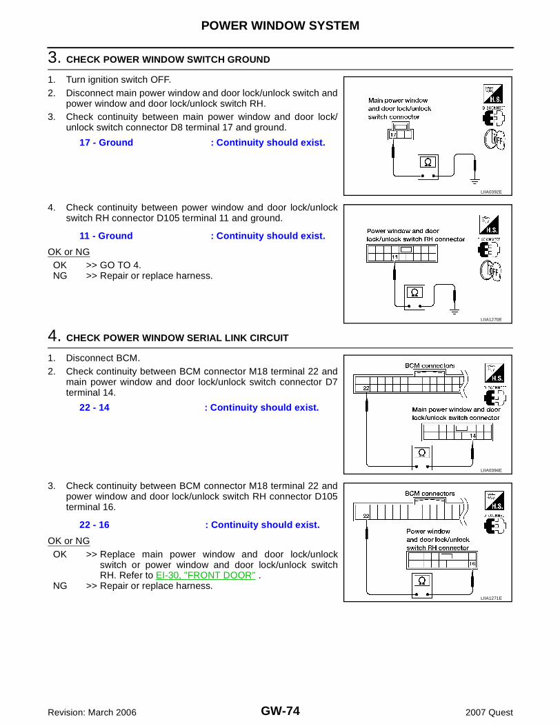
GW-74
POWER WINDOW SYSTEM
Revision: March 2006 2007 Quest
3. CHECK POWER WINDOW SWITCH GROUND
1. Turn ignition switch OFF.2. Disconnect main power window and door lock/unlock switch and
power window and door lock/unlock switch RH.3. Check continuity between main power window and door lock/
unlock switch connector D8 terminal 17 and ground.
4. Check continuity between power window and door lock/unlockswitch RH connector D105 terminal 11 and ground.
OK or NGOK >> GO TO 4.NG >> Repair or replace harness.
4. CHECK POWER WINDOW SERIAL LINK CIRCUIT
1. Disconnect BCM.2. Check continuity between BCM connector M18 terminal 22 and
main power window and door lock/unlock switch connector D7terminal 14.
3. Check continuity between BCM connector M18 terminal 22 andpower window and door lock/unlock switch RH connector D105terminal 16.
OK or NGOK >> Replace main power window and door lock/unlock
switch or power window and door lock/unlock switchRH. Refer to EI-30, "FRONT DOOR" .
NG >> Repair or replace harness.
17 - Ground : Continuity should exist.
LIIA0392E
11 - Ground : Continuity should exist.
LIIA1270E
22 - 14 : Continuity should exist.
LIIA0394E
22 - 16 : Continuity should exist.
LIIA1271E
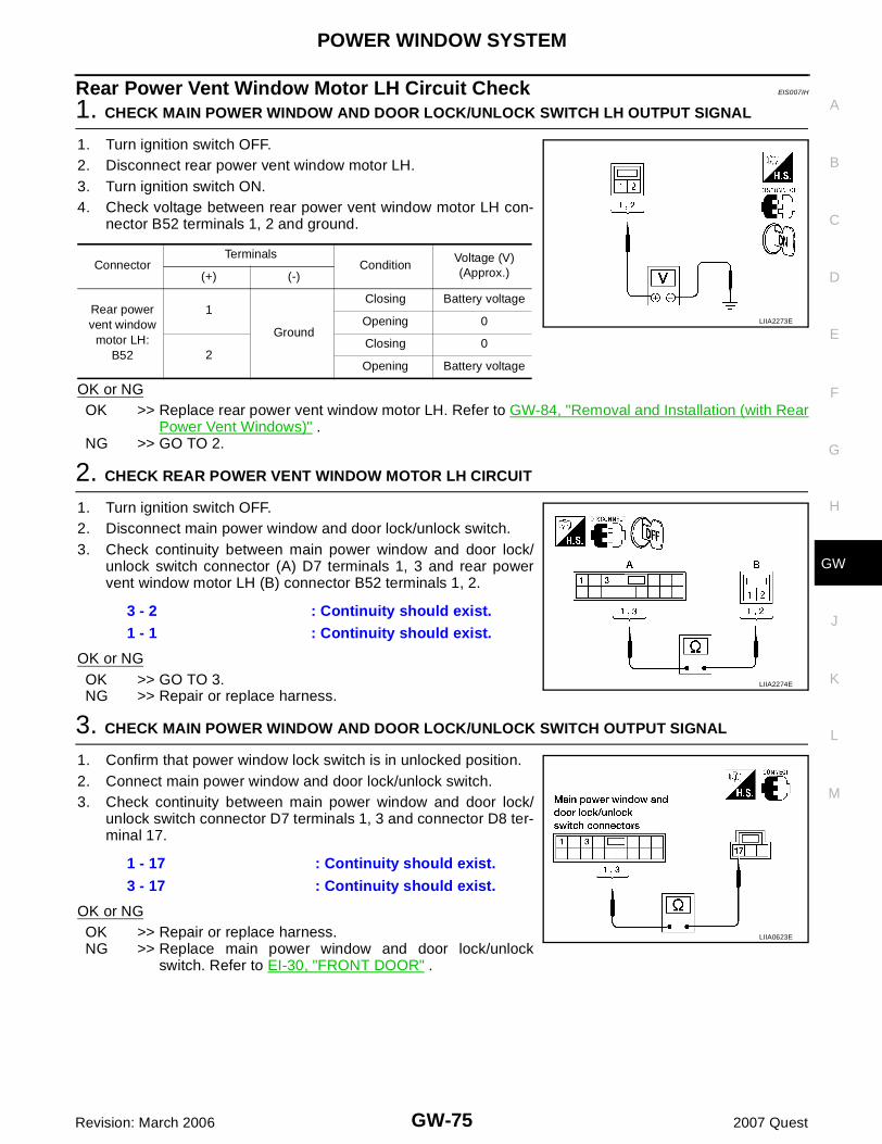
POWER WINDOW SYSTEM
GW-75
C
D
E
F
G
H
J
K
L
M
A
B
GW
Revision: March 2006 2007 Quest
Rear Power Vent Window Motor LH Circuit Check EIS007IH
1. CHECK MAIN POWER WINDOW AND DOOR LOCK/UNLOCK SWITCH LH OUTPUT SIGNAL
1. Turn ignition switch OFF.2. Disconnect rear power vent window motor LH.3. Turn ignition switch ON.4. Check voltage between rear power vent window motor LH con-
nector B52 terminals 1, 2 and ground.
OK or NGOK >> Replace rear power vent window motor LH. Refer to GW-84, "Removal and Installation (with Rear
Power Vent Windows)" .NG >> GO TO 2.
2. CHECK REAR POWER VENT WINDOW MOTOR LH CIRCUIT
1. Turn ignition switch OFF.2. Disconnect main power window and door lock/unlock switch.3. Check continuity between main power window and door lock/
unlock switch connector (A) D7 terminals 1, 3 and rear powervent window motor LH (B) connector B52 terminals 1, 2.
OK or NGOK >> GO TO 3.NG >> Repair or replace harness.
3. CHECK MAIN POWER WINDOW AND DOOR LOCK/UNLOCK SWITCH OUTPUT SIGNAL
1. Confirm that power window lock switch is in unlocked position.2. Connect main power window and door lock/unlock switch.3. Check continuity between main power window and door lock/
unlock switch connector D7 terminals 1, 3 and connector D8 ter-minal 17.
OK or NGOK >> Repair or replace harness.NG >> Replace main power window and door lock/unlock
switch. Refer to EI-30, "FRONT DOOR" .
ConnectorTerminals
ConditionVoltage (V)(Approx.)(+) (-)
Rear power vent window
motor LH: B52
1
Ground
Closing Battery voltage
Opening 0
2Closing 0
Opening Battery voltage
LIIA2273E
3 - 2 : Continuity should exist.
1 - 1 : Continuity should exist.
LIIA2274E
1 - 17 : Continuity should exist.
3 - 17 : Continuity should exist.
LIIA0623E
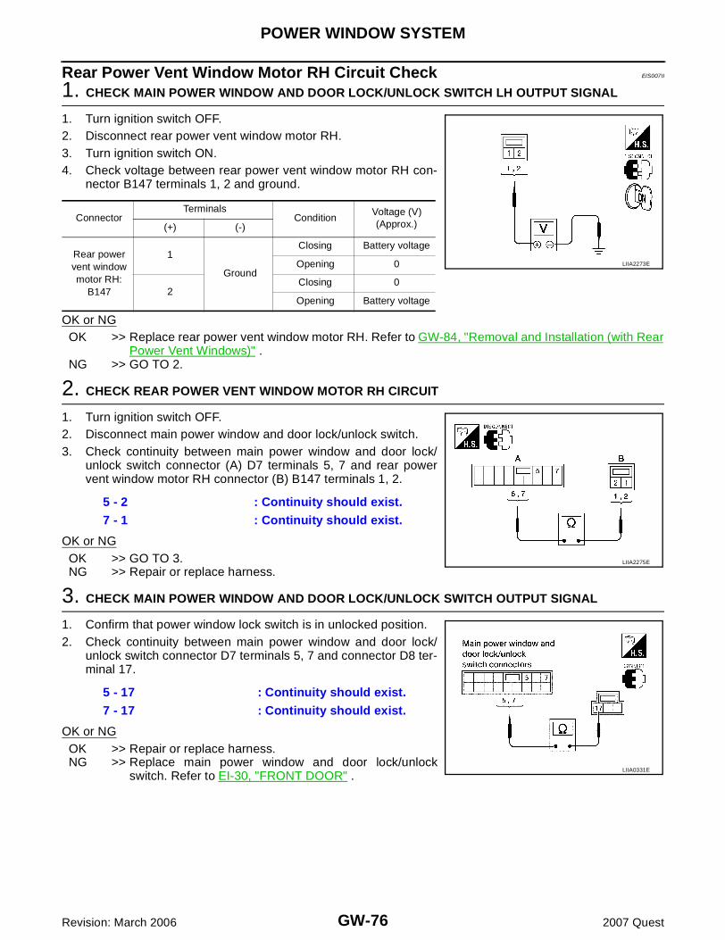
GW-76
POWER WINDOW SYSTEM
Revision: March 2006 2007 Quest
Rear Power Vent Window Motor RH Circuit Check EIS007II
1. CHECK MAIN POWER WINDOW AND DOOR LOCK/UNLOCK SWITCH LH OUTPUT SIGNAL
1. Turn ignition switch OFF.2. Disconnect rear power vent window motor RH.3. Turn ignition switch ON.4. Check voltage between rear power vent window motor RH con-
nector B147 terminals 1, 2 and ground.
OK or NGOK >> Replace rear power vent window motor RH. Refer to GW-84, "Removal and Installation (with Rear
Power Vent Windows)" .NG >> GO TO 2.
2. CHECK REAR POWER VENT WINDOW MOTOR RH CIRCUIT
1. Turn ignition switch OFF.2. Disconnect main power window and door lock/unlock switch.3. Check continuity between main power window and door lock/
unlock switch connector (A) D7 terminals 5, 7 and rear powervent window motor RH connector (B) B147 terminals 1, 2.
OK or NGOK >> GO TO 3.NG >> Repair or replace harness.
3. CHECK MAIN POWER WINDOW AND DOOR LOCK/UNLOCK SWITCH OUTPUT SIGNAL
1. Confirm that power window lock switch is in unlocked position.2. Check continuity between main power window and door lock/
unlock switch connector D7 terminals 5, 7 and connector D8 ter-minal 17.
OK or NGOK >> Repair or replace harness.NG >> Replace main power window and door lock/unlock
switch. Refer to EI-30, "FRONT DOOR" .
ConnectorTerminals
ConditionVoltage (V)(Approx.)(+) (-)
Rear power vent window motor RH:
B147
1
Ground
Closing Battery voltage
Opening 0
2 Closing 0
Opening Battery voltage
LIIA2273E
5 - 2 : Continuity should exist.
7 - 1 : Continuity should exist.
LIIA2275E
5 - 17 : Continuity should exist.
7 - 17 : Continuity should exist.
LIIA0331E

FRONT DOOR GLASS AND REGULATOR
GW-77
C
D
E
F
G
H
J
K
L
M
A
B
GW
Revision: March 2006 2007 Quest
FRONT DOOR GLASS AND REGULATOR PFP:80300
Removal and Installation EIS007IJ
FRONT DOOR GLASS Removal1. Remove the front door speaker. Refer to AV-88, "FRONT DOOR SPEAKER" .2. Remove the hole cover over rear glass bolt.3. Connect the battery negative cable.4. Temporarily reconnect the power window switch to the door harness.5. Operate the power window main switch to raise/lower the door glass until the door glass bolts can be
seen.6. Disconnect the battery negative cable.7. Remove the inside seal.8. Remove the door glass bolts.9. While holding the door window, raise it at the rear end to pull the
glass out of the sash toward the outside of the door.
WIIA0793E
1. Door glass run 2. Door glass regulator nuts 3. Regulator motor
LIIA1687E
GW-78
FRONT DOOR GLASS AND REGULATOR
Revision: March 2006 2007 Quest
INSTALLATIONInstallation is in the reverse order of removal.

FRONT DOOR GLASS AND REGULATOR
GW-79
C
D
E
F
G
H
J
K
L
M
A
B
GW
Revision: March 2006 2007 Quest
FRONT DOOR GLASS REGULATORRemoval1. Remove the front door speaker. Refer to AV-88, "FRONT DOOR SPEAKER" .2. Remove the hole cover over rear glass bolt.3. Connect the battery negative cable.4. Temporarily reconnect the power window switch to the door harness.5. Operate the power window main switch to raise/lower the door glass until the door glass bolts can be
seen.6. Disconnect the battery negative cable.7. Remove the door glass bolts.8. Raise the door glass up into the door frame/channel and hold in
place with a suitable tool (A).
9. Disconnect the harness connector for the regulator assembly.10. Remove the regulator nuts, and remove the regulator assembly.
INSPECTION AFTER REMOVALCheck the regulator assembly for the following items. If a malfunction is detected, replace or grease it.� Wire wear� Regulator deformationThe arrows in the figure show the application points of the bodygrease.
INSTALLATIONInstallation is in the reverse order of removal.Refer to GW-79, "FITTING INSPECTION AND SETTING AFTERINSTALLATION" .
DISASSEMBLY 1. Remove the regulator motor bolts.2. Remove the regulator motor from the regulator assembly.
ASSEMBLYAssembly is in the reverse order of disassembly.
FITTING INSPECTION AND SETTING AFTER INSTALLATION� Check that the glass is securely fit into the glass run groove.
WIIA0767E
LIIA0670E
Door glass bolts : 6.1 N·m (0.62 kg-m, 54 in-lb)
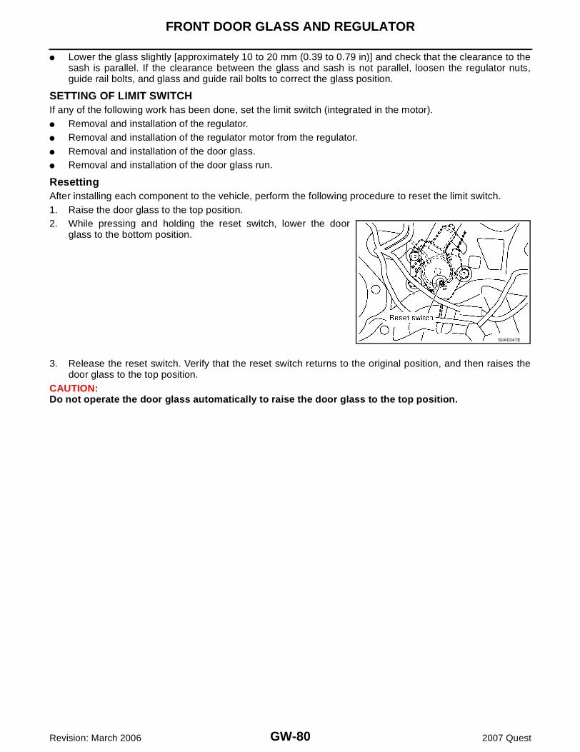
GW-80
FRONT DOOR GLASS AND REGULATOR
Revision: March 2006 2007 Quest
� Lower the glass slightly [approximately 10 to 20 mm (0.39 to 0.79 in)] and check that the clearance to thesash is parallel. If the clearance between the glass and sash is not parallel, loosen the regulator nuts,guide rail bolts, and glass and guide rail bolts to correct the glass position.
SETTING OF LIMIT SWITCHIf any of the following work has been done, set the limit switch (integrated in the motor).� Removal and installation of the regulator.� Removal and installation of the regulator motor from the regulator.� Removal and installation of the door glass.� Removal and installation of the door glass run.
ResettingAfter installing each component to the vehicle, perform the following procedure to reset the limit switch.1. Raise the door glass to the top position.2. While pressing and holding the reset switch, lower the door
glass to the bottom position.
3. Release the reset switch. Verify that the reset switch returns to the original position, and then raises thedoor glass to the top position.
CAUTION:Do not operate the door glass automatically to raise the door glass to the top position.
SIIA0347E

SLIDE DOOR GLASS
GW-81
C
D
E
F
G
H
J
K
L
M
A
B
GW
Revision: March 2006 2007 Quest
SLIDE DOOR GLASS PFP:82300
Removal and Installation EIS007IK
REMOVAL1. Apply protective tape around the slide door glass to protect the painted surface from damage.2. Remove glass using piano wire or power cutting tool and an inflatable pump bag.WARNING:When cutting the glass from the vehicle, always wear safety glasses and heavy gloves to help preventglass splinters from entering your eyes or cutting your hands.CAUTION:� When a slide door glass is to be reused, do not use a cutting knife or power cutting tool.� Be careful not to scratch the glass when removing.� Do not set or stand the glass on its edge. Small chips may develop into cracks.
INSTALLATIONInstallation is in the reverse order of removal.� Use a genuine NISSAN Urethane Adhesive Kit (if available) or equivalent and follow the instructions fur-
nished with it.� While the urethane adhesive is curing, open a window. This will prevent the glass from being forced out by
passenger compartment air pressure when a door is closed.� The rubber seal must be installed securely so that it is in position and leaves no gap.� Inform customer that the vehicle should remain stationary until the urethane adhesive has completely
cured (preferably 24 hours). Curing time varies with temperature and humidity.WARNING:� Keep heat and open flames away as primers and adhesives are flammable.
LIIA0673E

GW-82
SLIDE DOOR GLASS
Revision: March 2006 2007 Quest
� The materials contained in the kit are harmful if swallowed, and may irritate skin and eyes. Avoidcontact with the skin and eyes.
� Use in an open, well ventilated location. Avoid breathing the vapors. They can be harmful ifinhaled. if affected by vapor inhalation, immediately move to area with fresh air.
� Driving the vehicle before urethane adhesive has completely cured may affect the performance ofthe slide door glass in case of an accident.
CAUTION:� Do not use an adhesive which is past its usable term. Shelf life of this product is limited to six
months after the date of manufacture. Carefully adhere to the expiration or manufacture dateprinted on the box.
� Keep primers and adhesives in a cool dry place. ideally they should be stored in a refrigerator.� Do not leave primers and adhesive cartridge unattended with their caps off.� The vehicle should not be driven for at least 24 hours or until the urethane adhesive has com-
pletely cured. Curing time depends on temperature and humidity. The curing time will increaseunder lower temperature and lower humidities.
Repairing Water Leaks for Slide Door GlassLeaks can be repaired without removing and reinstalling glass.If water is leaking between the urethane adhesive material and body or glass, determine the extent of leakage.This can be done by applying water to the glass area while pushing glass outward.To stop the leak, apply primer (if necessary) and then urethane adhesive to the leak point.

SIDE WINDOW GLASS
GW-83
C
D
E
F
G
H
J
K
L
M
A
B
GW
Revision: March 2006 2007 Quest
SIDE WINDOW GLASS PFP:83300
Removal and Installation (without Rear Power Vent Windows) EIS007IL
REMOVAL1. Remove the rear pillar upper finisher. Refer to EI-33, "BODY SIDE TRIM" .2. Remove the rear side window latch bolts.3. Disconnect the antenna.4. Remove the side window front bolts and glass.
CAUTION:� Be careful not to scratch the glass when removing.� Do set or stand glass on its edge. Small chips may develop into cracks.
INSTALLATION1. Install the glass from outside to insure that it is even with the top and bottom of the opening. Tighten side
window front bolts to the specified torque.2. Install rear side window latch bolts.3. Connect the antenna.4. Install rear pillar upper finisher. Refer to EI-33, "BODY SIDE TRIM" .
WBIA0751E

GW-84
SIDE WINDOW GLASS
Revision: March 2006 2007 Quest
Removal and Installation (with Rear Power Vent Windows) EIS007IM
REMOVAL1. Remove the rear pillar upper finisher. Refer to EI-33, "BODY SIDE TRIM" .2. Disconnect the antenna.3. Disconnect the rear side window motor harness.4. Remove the rear side window motor bolts.5. Remove the side window front bolts and glass.
CAUTION:� Be careful not to scratch the glass when removing.� Do set or stand glass on its edge. Small chips may develop into cracks.
INSTALLATION1. Install the glass from outside to insure that it is even with the top and bottom of the opening. Tighten side
window front bolts to the specified torque.2. Install rear side window motor bolts.3. Connect the rear side window motor harness.4. Connect the antenna.5. Install rear pillar upper finisher. Refer to EI-33, "BODY SIDE TRIM" .
WBIA0751E
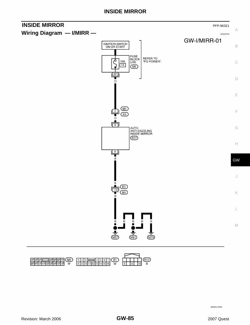
INSIDE MIRROR
GW-85
C
D
E
F
G
H
J
K
L
M
A
B
GW
Revision: March 2006 2007 Quest
INSIDE MIRROR PFP:96321
Wiring Diagram — I/MIRR — EIS007IN
WIWA1783E

GW-86
INSIDE MIRROR
Revision: March 2006 2007 Quest
Removal and Installation EIS007IO
REMOVAL1. Remove inside mirror finisher.2. Remove inside mirror screw.3. Slide the mirror upward to remove.4. Disconnect the connector.
INSTALLATIONInstallation is in the reverse order of removal.
LIIA0277E
1. Inside mirror 2. Inside mirror finisher

REAR WINDOW DEFOGGER
GW-87
C
D
E
F
G
H
J
K
L
M
A
B
GW
Revision: March 2006 2007 Quest
REAR WINDOW DEFOGGER PFP:25350
Component Parts and Harness Connector Location EIS007IP
System Description EIS007IQ
The rear window defogger system is controlled by BCM (body control module) and IPDM E/R (intelligentpower distribution module engine room). The rear window defogger operates only for approximately 15 minutes. Power is supplied at all times� through 20A fuses (No. 32 and 37, located in the IPDM E/R) � to rear window defogger relay terminals 3 and 6� through 50A fusible link (letter j , located in the fuse and fusible link box)� to BCM terminal 70.With the ignition switch turned to ON or START position, power is supplied� through 10A fuse [No.12, located in the fuse block (J/B)]� to rear window defogger relay terminal 1� through 10A fuse [No.16, located in the fuse block (J/B)]
1. A. Hood openerB. Rear window defogger relay B4
2. IPDM E/R E119, E121, E124 3. A. A-pillar LHB. BCM M18, M19 (view with instru-ment panel removed)
4. Door mirror LH (door mirror defog-ger) D13Door mirror RH (door mirror defog-ger) D113
5. Rear window defogger D504 (view of back door LH with back door upper finishers removed)
6. Rear window defogger ground con-nector D515 (view of back door RH with back door upper finishers removed)
7. Front air control M49, M50 (with automatic air conditioner)
8. Front air control M49, M50 (with manual air conditioner)
LIIA2456E

GW-88
REAR WINDOW DEFOGGER
Revision: March 2006 2007 Quest
� to BCM terminal 38� through 10A fuse [No. 2, located in the fuse block (J/B)]� to front air control terminal 15.Ground is supplied � to BCM terminal 67 � to front air control terminal 36� through body grounds M57, M61 and M79� to IPDM E/R terminals 38 and 60� through body grounds E9, E15 and E24. When front air control (rear window defogger switch) is turned to ON, ground is supplied � to BCM terminal 9� through front air control terminal 16 � through front air control terminal 36� through body grounds M57, M61 and M79.Then rear window defogger switch is illuminated.Then BCM recognizes that rear window defogger switch is turned to ON. Then it sends rear window defogger switch signals to IPDM E/R and display control unit (with color display) viaCAN communication (CAN-H, CAN-L).When IPDM E/R receives rear window defogger switch signals, ground is supplied� to rear window defogger relay terminal 2� through IPDM E/R terminal 52� through IPDM E/R terminal 60� through body grounds E9, E15 and E24. Then rear window defogger relay is energized. With power and ground supplied, rear window defogger filaments heat and defog the rear window.When rear window defogger relay is turned to ON (with door mirror defogger), power is supplied� through rear window defogger relay terminal 5� through fuse block (J/B) terminal 2Q� through 10A fuse [No. 8, located in the fuse block (J/B)]� through fuse block (J/B) terminal 5N� to door mirror defogger (LH and RH) terminal 6.Door mirror defogger (LH and RH) terminal 5 is grounded through body grounds M57, M61 and M79.With power and ground supplied, door mirror defogger filaments heat and defog the mirror.
CAN Communication System Description EIS007IR
Refer to LAN-4, "SYSTEM DESCRIPTION" .

REAR WINDOW DEFOGGER
GW-89
C
D
E
F
G
H
J
K
L
M
A
B
GW
Revision: March 2006 2007 Quest
Schematic EIS007IS
WIWA1784E

GW-90
REAR WINDOW DEFOGGER
Revision: March 2006 2007 Quest
Wiring Diagram — DEF — EIS007IT
WIWA1785E

REAR WINDOW DEFOGGER
GW-91
C
D
E
F
G
H
J
K
L
M
A
B
GW
Revision: March 2006 2007 Quest
WIWA1786E

GW-92
REAR WINDOW DEFOGGER
Revision: March 2006 2007 Quest
WIWA1787E

REAR WINDOW DEFOGGER
GW-93
C
D
E
F
G
H
J
K
L
M
A
B
GW
Revision: March 2006 2007 Quest
Terminal and Reference Value for BCM EIS007IU
Refer to BCS-12, "Terminals and Reference Values for BCM" .
Terminal and Reference Value for IPDM E/R EIS007IV
Refer to PG-27, "Terminals and Reference Values for IPDM E/R" .
Work Flow EIS007IW
1. Check the symptom and customer's requests.2. Understand the outline of system. Refer to GW-87, "System Description" .3. According to the trouble diagnosis chart, repair or replace the cause of the malfunction. Refer to GW-93,
"Trouble Diagnoses Symptom Chart" .4. Does rear window defogger operate normally? YES: GO TO 5, NO: GO TO 3.5. Inspection End.
CONSULT-II Function (BCM) EIS007IX
CONSULT-II can display each diagnostic item using the diagnostic test modes shown following.
CONSULT-II START PROCEDURERefer to GI-37, "CONSULT-II Start Procedure" .
DATA MONITORDisplay Item List
ACTIVE TESTDisplay Item List
Trouble Diagnoses Symptom Chart EIS007IY
� Make sure other systems using the signal of the following systems operate normally.
BCM diagnostic test item
Diagnostic mode Content
Inspection by part
WORK SUPPORTSupports inspections and adjustments. Commands are transmitted to the BCM for setting the status suitable for required operation, input/output signals are received from the BCM and received data is displayed.
DATA MONITOR Displays BCM input/output data in real time.
ACTIVE TEST Operation of electrical loads can be checked by sending drive signal to them.
SELF-DIAG RESULTS Displays BCM self-diagnosis results.
CAN DIAG SUPPORT MNTR
The results of transmit/receive diagnosis of CAN communication can be read.
ECU PART NUMBER BCM part number can be read.
CONFIGURATION Performs BCM configuration read/write functions.
Monitor item “Operation” Content
REAR DEF SW “ON/OFF”Displays “Press (ON)/others (OFF)” status determined with the rear window defogger switch.
IGN ON SW “ON/OFF” Displays “IGN (ON)/OFF” status determined with the ignition switch signal.
Test item Content
REAR WINDOW DEFOGGER Gives a drive signal to the rear window defogger to activate it.

GW-94
REAR WINDOW DEFOGGER
Revision: March 2006 2007 Quest
BCM Power Supply and Ground Circuit Check EIS007IZ
Refer to BCS-15, "BCM Power Supply and Ground Circuit Check" .
Symptom Diagnoses/Service procedure Refer to page
Rear window defogger and door mirror defoggers do not operate. (With door mirror defogger)
1. BCM power supply and ground circuit check BCS-15
2. IPDM E/R auto active test check PG-23
3. Rear window defogger switch circuit check GW-95
4. Rear window defogger power supply circuit check GW-96
5. Replace IPDM E/R PG-33
Rear window defogger does not operate. (Without door mirror defogger)
1. BCM power supply and ground circuit check BCS-15
2. IPDM E/R auto active test check PG-23
3. Rear window defogger switch circuit check GW-95
4. Rear window defogger power supply circuit check GW-96
5. Rear window defogger circuit check GW-98
6. Filament check GW-103
7. Replace IPDM E/R PG-33
Rear window defogger does not operate but both door mir-ror defoggers operate. (With door mirror defogger)
1. Rear window defogger circuit check GW-98
2. Filament check GW-103
Both door mirror defoggers do not operate but rear window defogger operates. (With door mirror defogger)
1. Door mirror defogger power supply circuit check GW-99
Door mirror LH defogger does not operate. 1. Door mirror LH defogger circuit check GW-100
Door mirror RH defogger does not operate. 1. Door mirror RH defogger circuit check GW-101
Rear window defogger switch does not light, and rear win-dow defogger is not displayed on the color display (if equipped), but rear window defogger operates.
1. Rear window defogger signal check GW-102

REAR WINDOW DEFOGGER
GW-95
C
D
E
F
G
H
J
K
L
M
A
B
GW
Revision: March 2006 2007 Quest
Rear Window Defogger Switch Circuit Check EIS007J0
1. CHECK REAR WINDOW DEFOGGER SWITCH OPERATION
With CONSULT-IICheck (“REAR DEF SW”, “IGN ON SW”) in DATA MONITOR modewith CONSULT-II.
Without CONSULT-II1. Turn ignition switch ON.2. Check voltage between BCM connector ground.
OK or NGOK >> Rear window defogger switch check is OK.NG >> GO TO 2.
2. CHECK REAR WINDOW DEFOGGER SWITCH CIRCUIT HARNESS CONTINUITY
1. Turn ignition switch OFF.2. Disconnect BCM and front air control.3. Check continuity between BCM connector M18 (A) terminal 9
and front air control connector M49 (B) terminal 16.
4. Check continuity between BCM connector M18 terminal 9 andground
OK or NGOK >> GO TO 3.NG >> Repair or replace harness.
When rear window defogger switch is turned to ON
REAR DEF SW: ON
When ignition switch is turned to ON
IGN ON SW: ON
PIIA2373E
ConnectorTerminals
ConditionVoltage (V)(Approx.)(+) (-)
M18 9 Ground
Rear window defogger switch is pressed.
0
Rear window defogger switch is OFF.
5
LIIA0402E
9 - 16 : Continuity should exist.
9 - Ground : Continuity should not exist.LIIA2459E

GW-96
REAR WINDOW DEFOGGER
Revision: March 2006 2007 Quest
3. CHECK BCM OUTPUT SIGNAL
1. Connect BCM.2. Turn ignition switch ON.3. Check voltage between BCM connector M18 terminal 9 and
ground.
OK or NGOK >> Replace front air control. Refer to ATC-160, "CONTROL
UNIT" .NG >> Replace BCM. Refer to BCS-25, "Removal and Installa-
tion of BCM" .
Rear Window Defogger Power Supply Circuit Check EIS007J1
1. CHECK FUSES
Check if any of the following fuses in fuse block (J/B) and IPDM E/R are blown.
OK or NGOK >> GO TO 2.NG >> If fuse is blown, be sure to eliminate cause of malfunction before installing new fuse, refer to PG-
4, "POWER SUPPLY ROUTING CIRCUIT" .
2. CHECK REAR WINDOW DEFOGGER RELAY POWER SUPPLY CIRCUIT
1. Turn ignition switch OFF.2. Disconnect rear window defogger relay.3. Turn ignition switch ON.4. Check voltage between rear window defogger relay connector
and ground.
OK or NGOK >> GO TO 3.NG >> Repair or replace harness.
9 - Ground : Approx. 5V
LIIA0402E
COMPONENT PARTS TERMINAL NO. (SIGNAL) AMPERE FUSE NO.
Fuse block (J/B) 2T (Ignition power supply) 10A 12
IPDM E/R5 (Battery power supply) 20A 32
6 (Battery power supply) 20A 37
ConnectorTerminals Voltage (V)
(Approx.)(+) (-)
B4
1
Ground Battery voltage3
6
PIIA4233E
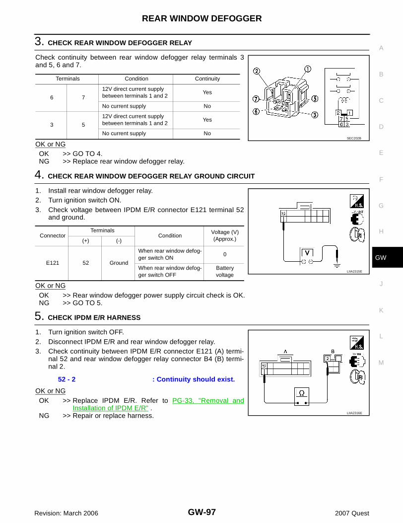
REAR WINDOW DEFOGGER
GW-97
C
D
E
F
G
H
J
K
L
M
A
B
GW
Revision: March 2006 2007 Quest
3. CHECK REAR WINDOW DEFOGGER RELAY
Check continuity between rear window defogger relay terminals 3and 5, 6 and 7.
OK or NGOK >> GO TO 4.NG >> Replace rear window defogger relay.
4. CHECK REAR WINDOW DEFOGGER RELAY GROUND CIRCUIT
1. Install rear window defogger relay.2. Turn ignition switch ON.3. Check voltage between IPDM E/R connector E121 terminal 52
and ground.
OK or NGOK >> Rear window defogger power supply circuit check is OK.NG >> GO TO 5.
5. CHECK IPDM E/R HARNESS
1. Turn ignition switch OFF.2. Disconnect IPDM E/R and rear window defogger relay.3. Check continuity between IPDM E/R connector E121 (A) termi-
nal 52 and rear window defogger relay connector B4 (B) termi-nal 2.
OK or NGOK >> Replace IPDM E/R. Refer to PG-33, "Removal and
Installation of IPDM E/R" .NG >> Repair or replace harness.
Terminals Condition Continuity
6 7
12V direct current supply between terminals 1 and 2
Yes
No current supply No
3 5
12V direct current supply between terminals 1 and 2
Yes
No current supply NoSEC202B
ConnectorTerminals
ConditionVoltage (V)(Approx.)(+) (-)
E121 52 Ground
When rear window defog-ger switch ON
0
When rear window defog-ger switch OFF
Battery voltage
LIIA2315E
52 - 2 : Continuity should exist.
LIIA2316E
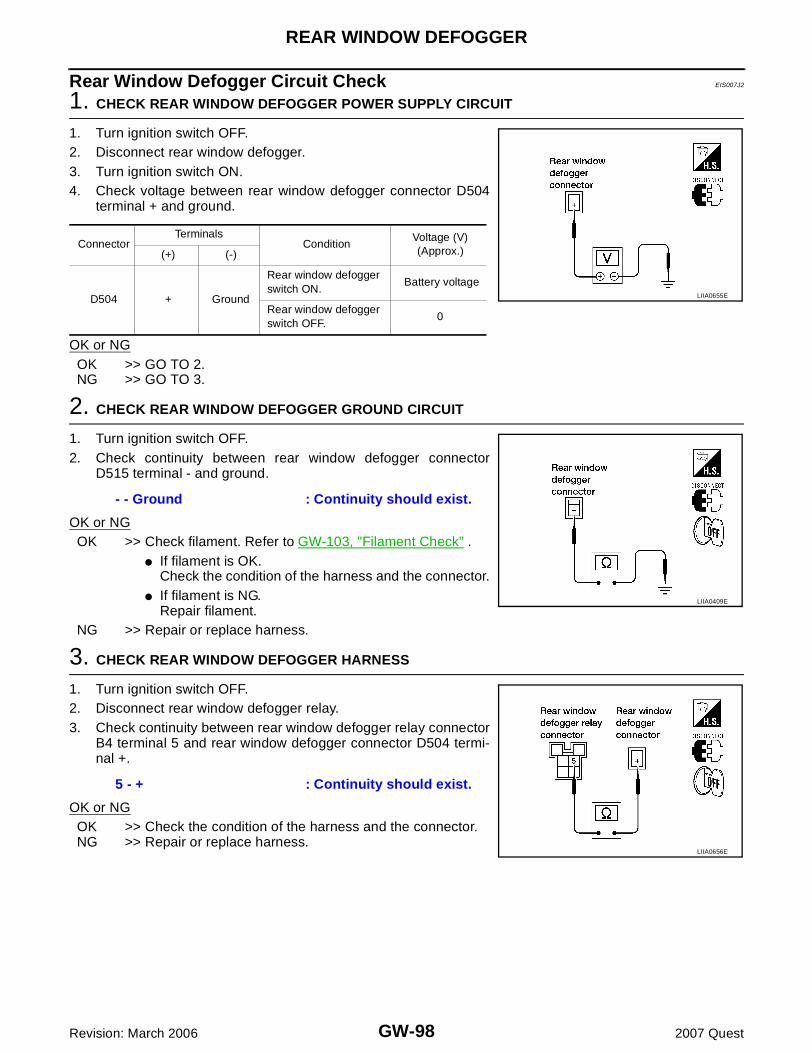
GW-98
REAR WINDOW DEFOGGER
Revision: March 2006 2007 Quest
Rear Window Defogger Circuit Check EIS007J2
1. CHECK REAR WINDOW DEFOGGER POWER SUPPLY CIRCUIT
1. Turn ignition switch OFF.2. Disconnect rear window defogger.3. Turn ignition switch ON.4. Check voltage between rear window defogger connector D504
terminal + and ground.
OK or NGOK >> GO TO 2.NG >> GO TO 3.
2. CHECK REAR WINDOW DEFOGGER GROUND CIRCUIT
1. Turn ignition switch OFF.2. Check continuity between rear window defogger connector
D515 terminal - and ground.
OK or NGOK >> Check filament. Refer to GW-103, "Filament Check" .
� If filament is OK.Check the condition of the harness and the connector.
� If filament is NG.Repair filament.
NG >> Repair or replace harness.
3. CHECK REAR WINDOW DEFOGGER HARNESS
1. Turn ignition switch OFF.2. Disconnect rear window defogger relay.3. Check continuity between rear window defogger relay connector
B4 terminal 5 and rear window defogger connector D504 termi-nal +.
OK or NGOK >> Check the condition of the harness and the connector.NG >> Repair or replace harness.
ConnectorTerminals
ConditionVoltage (V)(Approx.)(+) (-)
D504 + Ground
Rear window defogger switch ON.
Battery voltage
Rear window defogger switch OFF.
0
LIIA0655E
- - Ground : Continuity should exist.
LIIA0409E
5 - + : Continuity should exist.
LIIA0656E

REAR WINDOW DEFOGGER
GW-99
C
D
E
F
G
H
J
K
L
M
A
B
GW
Revision: March 2006 2007 Quest
Door Mirror Defogger Power Supply Circuit Check EIS007J3
1. CHECK FUSE
Check if the following fuse in fuse block (J/B) is blown.
OK or NGOK >> GO TO 2.NG >> If fuse is blown, be sure to eliminate cause of malfunction before installing new fuse. Refer to PG-
4, "POWER SUPPLY ROUTING CIRCUIT" .
2. CHECK DOOR MIRROR DEFOGGER POWER SUPPLY CIRCUIT 1
1. Turn ignition switch ON.2. Check voltage between fuse block (J/B) connector and ground.
OK or NGOK >> GO TO 3.NG >> Repair or replace harness.
3. CHECK DOOR MIRROR DEFOGGER POWER SUPPLY CIRCUIT 2
Check voltage between fuse block (J/B) connector and ground.
OK or NGOK >> GO TO 4. NG >> Replace fuse block (J/B).
4. CHECK DOOR MIRROR DEFOGGER CIRCUIT
1. Turn ignition switch OFF.2. Disconnect fuse block (J/B) and door mirror LH or RH.3. Check continuity between fuse block (J/B) connector M3 termi-
nal 5N and door mirror connector D13 (LH) or D113 (RH) termi-nal 6.
OK or NGOK >> GO TO 5.NG >> Repair or replace harness.
COMPONENT PARTS TERMINAL NO. (SIGNAL) AMPERE FUSE NO.
Fuse block (J/B) 5N (Battery power supply) 10A 8
ConnectorTerminals
ConditionVoltage (V)(Approx.)(+) (-)
E30 2Q Ground
Rear window defogger switch ON
Battery voltage
Rear window defogger switch OFF
0
LIIA0411E
ConnectorTerminals
ConditionVoltage (V)(Approx.)(+) (-)
M3 5N Ground
Rear window defogger switch ON
Battery voltage
Rear window defogger switch OFF
0
LIIA0412E
5N - 6 : Continuity should exist.
LIIA0657E

GW-100
REAR WINDOW DEFOGGER
Revision: March 2006 2007 Quest
5. CHECK DOOR MIRROR DEFOGGER GROUND CIRCUIT
Check continuity between each door mirror connector D13 (LH) orD113 (RH) terminal 5 and ground.
OK or NGOK >> GO TO 6.NG >> Repair or replace harness.
6. CHECK DOOR MIRROR DEFOGGER
Check continuity between each door mirror terminals 5 and 6.
OK or NGOK >> Repair or replace harness.NG >> Replace malfunctioning door mirror LH or RH. Refer to
GW-107, "Door Mirror Assembly" .
Door Mirror LH Defogger Circuit Check EIS007J4
1. CHECK DOOR MIRROR DEFOGGER POWER SUPPLY CIRCUIT
1. Turn ignition switch OFF.2. Disconnect door mirror LH. 3. Turn ignition switch ON.4. Check voltage between door mirror LH connector and ground.
OK or NGOK >> GO TO 2.NG >> Repair or replace harness.
5 - Ground : Continuity should exist.
LIIA0658E
6 - 5 : Continuity should exist.
LIIA2457E
ConnectorTerminals
ConditionVoltage (V)(Approx.)(+) (-)
D13 6 Ground
Rear window defogger switch ON
Battery voltage
Rear window defogger switch OFF
0LIIA2212E

REAR WINDOW DEFOGGER
GW-101
C
D
E
F
G
H
J
K
L
M
A
B
GW
Revision: March 2006 2007 Quest
2. CHECK DOOR MIRROR DEFOGGER GROUND CIRCUIT
1. Turn ignition switch OFF.2. Check continuity between door mirror LH connector D13 termi-
nal 5 and ground.
OK or NGOK >> GO TO 3.NG >> Repair or replace harness.
3. CHECK DOOR MIRROR DEFOGGER
Check continuity between door mirror LH terminals 5 and 6.
OK or NGOK >> Repair or replace harness.NG >> Replace door mirror LH. Refer to GW-107, "Door Mirror
Assembly" .
Door Mirror RH Defogger Circuit Check EIS007J5
1. CHECK DOOR MIRROR DEFOGGER POWER SUPPLY CIRCUIT
1. Turn ignition switch OFF.2. Disconnect door mirror RH.3. Turn ignition switch ON.4. Check voltage between door mirror RH connector and ground.
OK or NGOK >> GO TO 2.NG >> Repair or replace harness.
5 - Ground : Continuity should exist.
LIIA0658E
6 - 5 : Continuity should exist.
LIIA2457E
ConnectorTerminals
ConditionVoltage (V)(Approx.)(+) (-)
D113 6 Ground
Rear window defogger switch ON
Battery voltage
Rear window defogger switch OFF
0LIIA2212E

GW-102
REAR WINDOW DEFOGGER
Revision: March 2006 2007 Quest
2. CHECK DOOR MIRROR DEFOGGER GROUND CIRCUIT
1. Turn ignition switch OFF.2. Check continuity between door mirror RH connector D113 termi-
nal 5 and ground.
OK or NGOK >> GO TO 3.NG >> Repair or replace harness.
3. CHECK DOOR MIRROR DEFOGGER
Check continuity between each door mirror RH connector D113 ter-minals 5 and 6.
OK or NGOK >> Repair or replace harness.NG >> Replace door mirror RH. Refer to GW-107, "Door Mirror
Assembly" .
Rear Window Defogger Signal Check EIS007J6
1. CHECK AV COMMUNICATION LINE
AV communication line check is executed. Refer to AV-165, "CAN Communication Line Check (With ColorDisplay)" .
OK or NGOK >> GO TO 2.NG >> Replace display control unit. Refer to AV-169, "DISPLAY CONTROL UNIT" .
2. CHECK CAN COMMUNICATION LINE
CAN communication line check is executed. Refer to AV-165, "CAN Communication Line Check (With ColorDisplay)" .OK or NG
OK >> Check the condition of the harness and the connector.NG >> In addition, it is necessary to check CAN communication line. Refer to AV-165, "CAN Communica-
tion Line Check (With Color Display)" .
5 - Ground : Continuity should exist.
LIIA0658E
6 - 5 : Continuity should exist.
LIIA2457E
Is rear window defogger displayed on the display?

REAR WINDOW DEFOGGER
GW-103
C
D
E
F
G
H
J
K
L
M
A
B
GW
Revision: March 2006 2007 Quest
Filament Check EIS007J7
1. When measuring voltage, wrap tin foil around the top of the neg-ative probe. Then press the foil against the wire with your finger.
2. Attach probe circuit tester (in Volt range) to middle portion ofeach filament.
3. If a filament is burned out, circuit tester registers 0 or batteryvoltage.
4. To locate burned out point, move probe to left and right along fil-ament. Test needle will swing abruptly when probe passes thepoint.
Filament Repair EIS007J8
REPAIR EQUIPMENT� Conductive silver composition (DuPont No. 4817 or equivalent)� Ruler 30 cm (11.8 in) long� Drawing pen� Heat gun� Alcohol� Cloth
SEL122R
SEL263
SEL265

GW-104
REAR WINDOW DEFOGGER
Revision: March 2006 2007 Quest
REPAIRING PROCEDURE1. Wipe broken heat wire and its surrounding area clean with a
cloth dampened in alcohol.2. Apply a small amount of conductive silver composition to tip of
drawing pen.Shake silver composition container before use.
3. Place ruler on glass along broken line. Deposit conductive silvercomposition on break with drawing pen. Slightly overlap existingheat wire on both sides [preferably 5 mm (0.20 in)] of the break.
4. After repair has been completed, check repaired wire for conti-nuity. This check should be conducted 10 minutes after silvercomposition is deposited.Do not touch repaired area while test is being conducted.
5. Apply a constant stream of hot air directly to the repaired areafor approximately 20 minutes with a heat gun. A minimum dis-tance of 3 cm (1.2 in) should be kept between repaired area andhot air outlet.If a heat gun is not available, let the repaired area dry for 24hours.
PIIA0215E
SEL012D
SEL013D

DOOR MIRROR
GW-105
C
D
E
F
G
H
J
K
L
M
A
B
GW
Revision: March 2006 2007 Quest
DOOR MIRROR PFP:96301
Automatic Drive Positioner Reverse Tilt Mirror EIS007J9
Automatic drive positioner reverse tilt mirror. Refer to SE-11, "AUTOMATIC DRIVE POSITIONER" .

GW-106
DOOR MIRROR
Revision: March 2006 2007 Quest
Wiring Diagram — MIRROR — EIS007JA
WIWA1788E
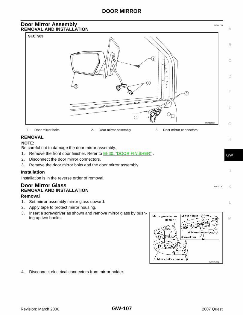
DOOR MIRROR
GW-107
C
D
E
F
G
H
J
K
L
M
A
B
GW
Revision: March 2006 2007 Quest
Door Mirror Assembly EIS007JB
REMOVAL AND INSTALLATION
REMOVAL NOTE:Be careful not to damage the door mirror assembly.1. Remove the front door finisher. Refer to EI-30, "DOOR FINISHER" .2. Disconnect the door mirror connectors.3. Remove the door mirror bolts and the door mirror assembly.
InstallationInstallation is in the reverse order of removal.
Door Mirror Glass EIS007JC
REMOVAL AND INSTALLATIONRemoval1. Set mirror assembly mirror glass upward.2. Apply tape to protect mirror housing.3. Insert a screwdriver as shown and remove mirror glass by push-
ing up two hooks.
4. Disconnect electrical connectors from mirror holder.
WIIA0790E
1. Door mirror bolts 2. Door mirror assembly 3. Door mirror connectors
WIIA0160E
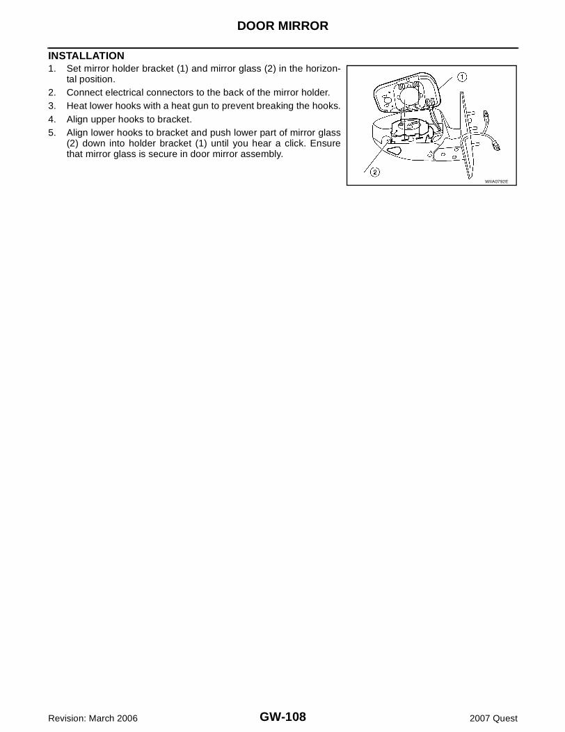
GW-108
DOOR MIRROR
Revision: March 2006 2007 Quest
INSTALLATION1. Set mirror holder bracket (1) and mirror glass (2) in the horizon-
tal position.2. Connect electrical connectors to the back of the mirror holder.3. Heat lower hooks with a heat gun to prevent breaking the hooks.4. Align upper hooks to bracket.5. Align lower hooks to bracket and push lower part of mirror glass
(2) down into holder bracket (1) until you hear a click. Ensurethat mirror glass is secure in door mirror assembly.
WIIA0792E