Embed Size (px)
Citation preview

REPORT ON PBASE I GEOLOGY, S O I L GEOCHEMISTRY SURVEY,
INDUCED POLARIZATION SURVEY AND DIAMOND DRILLING
EMMA PROPERTY (Emma, Emma 1 to 22, Su 1 to 3 C l a i m s ) Victoria, Nanaimo Mining Divisions
NTS 92F/2, 4g010'N Lat., 124O35'W Long.
for AU RESOURCES LTD.
February 29, 1988
G.R. C o p e , B . S c .
VOLUME 3 OF 4 -

Appendix VIa
IP EQUIPMENT SPECIFICATIONS

' Induced T
I -t ' Polarization I
T Receiver
DESCRIPTION The Huntec M-4 is a microprocessor based receiver for time and frequency domain IP and complex resistivity measurement. It i s
Easy to operate. One switch starts a measurement, of up to 29 quantities simultaneously. The optional Cassette DataLogger records them all in seconds. Calibration, gain setting and SP buckout are all automatic.
Reliable. Using advanced digital signal processing tech- niques, the M-4 delivers consistently accurate data even in noisy, highly conductive areas. For mechanical reliability i t i s packaged in a rugged aluminum case for backpack or hand carrying.
Versatile. The operator may adjust delay and integration times, operating frequency and other measurement parameters, to adapt to a wide range of survey conditions and requirements. An independent reference channel facilitates drillhole and underground work, and guarantees transmitter-receiver syn- chronization in high-noise conditions.
Highly accurate. With a frequency bandwidth of 100 Hz and noise-cancelling digital signal stacking, the M-4 delivers very precise results. The details are summarized in a table overleaf.
Sensitive. The same features that make the M-4 accurate allow detection of very weak signals. The Huntec receiver requires lower transmitter power than any other, for a given set of operating conditions. Automatic correction for drifts in self- potential and gain allow long stacking times for significant signal-to-noise improvements.
Intelligent. Under the control of a powerful 16-bit micro- processor, the M-4 calibrates and tests itself between measure- ments. Coded error messages, flashed onto ihe display, inform the operator of any malfunction.
The M-4 Receiver is complemented by Huntec's new M-4 transmitters, which offer precisely timed constant-current out- put and both time and frequency domain waveforms, compati-
ble with the receiver's accuracy and multi-mode measurement capabilities. The RL-2 Reference Isolator connects any IP trans- mitter to the receiver's reference channel. The GeoDataBase field computer reads, stores and processes data from M-4 cas- settes. Contact Huntec for more information on the benefits offered by the M-4 product line.
FEATURES
Time and Frequency domain IP and Complex Resistivity operation
Simultaneous Time domain and Complex Resistivity measurement Automatic calibration
gain setting SP cancellation fault diagnosis filter tuning
Independent reference channel for drillhole and under- ground work 33 quantities, displayable on large 3% digit low-temperature liquid-crystal readout Analogue meter for source resistance measurement lo9 ohms differential input resistance 8 hours continuous operation with replaceable, recharge- able nickel-cadmium battery pack (2 supplied) Optional Cassette DataLogger fits inside case, has read-after- write error checking. Up to 350 stations per tape. Conveniently packaged for backpacking or hand carrying 100 Hz bandwidth, fine time-resolution Advanced digital signal stacking Delivers reliable, accurate data in noisy, highly conductive areas.

SPKIFICATIONS
Inputs Signal Chnnel
Range: 5 x l o - ' to 10 volts. Automatic ranging. Overload indication
Resistance: Greater than 10' ohms differential Bandwidth: 100 Hz SP Cancellation: - 5 to + 5 volts (automatic) Protection: Low-leakage diode clamps, gas dis-
charge surge arrestors, replaceable fuses.
Reference Channel
Level: 500 mV minimum, 10 volts peak max- imum, overload .indication
Resistance: 2 x 10' ohms differential Controls and Functions
Operating Controls
Keypad: 16 keys, calculator format, function associated with each key.
Reference Registers: Keypad may be used to store up to ten 3 '/2
digit numeric values with floating decim- al point, to represent station number, line number, operator, time, date, weather, transmitter current, etc. for recording on cassette.
Programming Controls
Sub-panel: All programming controls are on a co- vered sub-panel, not accessible during normal operation.
Thumbwheel Switches: Select delay time to in milliseconds,
chargeability window tp in milliseconds; operating frequency; PFE frequency ratio.
Displayable Quantities
Time domain: Primary voltage; self-potential; charge- ability (total or each of 10 windows of equal width); phases of odd harmonics 3 to 15; amplitudes of odd harmonics 1 to 15; cycle count; repeating display of polarization potential and total chargeability.
Freq.domain: Primary amplitude; Percent Frequency Effect; self-potential; cycle count.
Complex Phases of odd harmonics 3 to 15; ampli- Resistivity: tudes of odd harmonics 1 to 15; fun-
damental phase (with ref. input); cycle count.
Any mode: Battery voltage, Frequency error.
Outputs
Displays
Digital Display: 3% digit, low-temperature liquid crystal display. Indicates measurement results and diagnostic error messages.
Analogue Meter: Ohms scale for source resistance; also gives qualitative indication of signal-to- noise ratio.
Cassette DataLogger (Optional)
Description: Accommodated within M-4 chassis. If not acquired with receiver, may be retro- fitted by user at any time. Two recording modes:
Partial: All sub-panel settings, measurement re- sults, and contents of reference registers are recorded (2 seconds recording time).
Full: As in partial mode, but also recorded is one cycle of averaged signal waveform (28 seconds recording time). If external
reference is used, one cycle of reference waveform is also recorded (60 seconds recording time). Extra memory and soh- ware available to average and store the reference waveform for advanced offline resistivity computation.
Format: ANSI/ECMA/ISO standard for saturation recording: 80 bytes/record, all data re- corded in ASCII code.
Verification: Read-after-write data verification (auto- matic)
Mechanical
M-4 Receiver with battery pack: 45 cm x 33 cm x 14 cm, 10.0 kg M-4 Receiver with battery pack and Cassette DataLogger: Dimensions as above, 1 1.0 kg Replaceable Battery pack: 33 cm x 1 1 cm x 4.5 cm, 3 kg
Environmental
Temperature: Operation: - 20°C to + 55°C Storage: - 40'C to + 70°C
Humidity: Moisture-proof, operable in light drizzle. Altitude: - 1,525 rn to +7,775 m Shock,Vibration: Suitable for transport in bush vehicles.
OUTPUT ACCURACY AND SENSITIVITY
rn~lliradtanr volls 41% wln woods %
2 rndli. 1% )OH2 ,ad,a I.C BOHr
t 1% t 1% O.I%(II O.'%l'l lull urk
1) Frequency domain mode:at harmonic frequencies up to 15 Hz, increases to not more than 5 milliradians at 80 Hz.
Time domain mode:at harmonic frequencies up to 7.5 Hz, increases to not more than 5 milliradians at 30 Hz.
2) of total OFF time 3) Full scale defined as 100% PFE. Cassette Data: recorded in ASCII, 9 digits with decimal point fixed for four decimal digits. Display Data: 3% digits, iloating decimal point Resolution of averaged waveform limited by N O converter to one part or 4096 x (square root of cycle count). Resolution of reference waveform (not averaged) limited by available memory to one part in 256. Additional memory and averaging software available as option.
CHARGEABILITY WINDOWS

DESCRIPTION The HUNTEC M-4 2.5 kW Induced Polarization transmitter is designed for time domain, frequency domain (PFE) and complex resistivity applications. The unit converts primary 400 Hz ac power from
1 an engine-alternator set to a regulated dc output current, set by the operator. Current regulation eliminates output waveform distortion due to elec- i trode polarization effects. It i s achieved in the trans- mitter by varying the alternator field currents. The transmitter is equipped with dummy loads to smooth 1 out generator load variations.
1 FEATURES I Solid-state switching for long life and precise timing.
Open circuit during the "off" time ensures no counter current flow. 1 Resistance measurement for load matching. Precision crystal controlled timing. Failsafe operation protects against short-circuit and overvoltage. Automatic regulation of output current eliminates errors due to changing polarization potential and
1 load resistance.
M-4 SERIES
Induced Polarizatior Resistivity 2.5 kW I ransm ltter
N Transmitter
A) Power input: 96 - 144 V line to line 3 phase 400 Hz (from Huntec generator set)
B) Output: Voltage: 150 - 2200 V dc in 8 steps Current: 0.2 - 7 A regulated* *
C) Current regulation: Less than kO.l% change for & lo% load change
D) Output frequency: 0.0625 Hz to 1 Hz (time domain, complex resistivity) 0.0625 Hz to 4 Hz (frequency domain) selectable from front panel An additional range of frequencies be- tween 0.78 and 5.0 Hz i s available and can be selected by an internal switch.
E ) Frequency accuracy: 250 ppm -30°C to + 60°C
F) Output duty cycle: 0.5 to 0.9375 in increments of 0.0625 Tonl(Ton+To~) (time domainj
0.9375 (complex resistivity) 0.75 (frequency domain)
GI Output current meter: Two ranges: 0-5 A and 0-1 0 A
HI Ground resistance meter: Two ranges: 0-10 kQ and 0-100 kR
I) Input voltage meter: 0-1 50 V 1) Dummy load: Two levels: 500 W and 1 .i5 kW K) Temperature range: -34°C to + 50°C 1) Size: 53cmx43cmx29cm M) Weight: 26 kg
*'Smaller currents are obtainable, but outside the current regulation range the transmitter voltage is regulated, not the current.

SPECIFICATIONS
M-4 2.5 kW Engine Driven Alternator Output: 120 V ac 400 Hz 3.5 kVA maximum Engine: 6 kW air cooled, single cylinder four
cycle piston engine wtth manual start Fuel: Regular grade r i i n e , tank capacity
3.8 L to give 4 h uration Alternator: Delta connected heavy duty automobile
type, belt driven, air cooled Construction: Tubular protective carrying frame with
resiliently mounted engine and alternator
Size: 51cmx48cmx76cm
Weight (dry): 61 kg

Appendix VIb
NOTES ON IP/RESISTIVITY

NOTES ON IP/RESISTIVITY SURVEYS
Genera l
Induced P o l a r i z a t i o n ( I P ) / r e s i s t i v i t y su rveys a r e commonly conducted i n
t h e time domain and f requency domain, and less f r e q u e n t l y , as s p e c t r a l o r
complex r e s i s t i v i t y measurements. There a r e a v a r i e t y of g e o m e t r i c a l
a r r a y s t h a t can be employed.
The p r e s e n t su rvey employed time-domain measurements us ing t h e d ipo le -
d i p o l e a r r a y . Measurements were made w i t h t h e Huntec Mk I V r e c e i v e r and
2.5 kw t r a n s m i t t e r .
The f o l l o w i n g d i s c u s s i o n sets o u t i n some d e t a i l t h e p r i n c i p l e s and pro-
c e d u r e s of t h e IP method a s r e l a t e d t o t h e p r e s e n t survey.
Time Domain Hethod
As shown i n F i g u r e 1, i n t h e time domain a modi f i ed , square-wave c u r r e n t
c o n s i s t i n g of " o n / o f f / o n / o f f " c y c l e s of e q u a l d u r a t i o n i s t r a n s m i t t e d
i n t o t h e ground through a p a i r of e l e c t r o d e s ( c u r r e n t d i p o l e ) . The
p r imary (Vp) and secondary (V,) v o l t a g e s genera ted i n t h e ground a r e
measured a t a n o t h e r p a i r of e l e c t r o d e s ( p o t e n t i a l d i p o l e ) . The primary
v o l t a g e , measured d u r i n g t h e "on" c u r r e n t c y c l e s , i s a f u n c t i o n of t h e
e l e c t r i c a l r e s i s t i v i t y of t h e ground. The secondary v o l t a g e , measured
d u r i n g " o f f " c u r r e n t c y c l e s , is t h e IP e f f e c t which r e f l e c t s t h e amount
o f p o l a r i z a b l e m i n e r a l s , such a s m e t a l l i c s u l p h i d e s , g r a p h i t e , e t c . , i n
t h e ground.
The a p p a r e n t r e s i s t i v i t y of t h e ground i s n o t d i r e c t l y measured, b u t i s
o b t a i n e d by a mathemat ica l formula u t i l i z i n g t h e primary v o l t a g e v a l u e ,
t h e c u r r e n t ou tpu t from t h e t r a n s m i t t e r a t t h e same i n s t a n t and a geo-
m e t r i c a l c o n s t a n t dependent on t h e a r r a y type being used:


where: a = apparent resistivity in ohm-meters
Vp = primary voltage (volts)
I = transmitted current (amps)
a = electrode spacing in meters
F = geometrical factor depending on the electrode array used.
The Huntec Mk IV system measures the secondary voltage or IP effect at 10
time intervals of equal width. The width of the time window (Tp) and the
length of the delay (Td) between the start of an "off" cycle and the
beginning of the IP measurement are adjustable to suit the conditions of
the survey. In the present survey, these were set at 100 msec and 100
msec, respectively, and the IP effect was recorded for each of five
individual time windows (MI, M3, Mg, M7 and Mg) and for the
total decay voltage (MT). The secondary voltage divided by the primary
voltage yields the parameter chargeability in milliseconds.
The decay curve constructed from the ten chargeability observations is
generally in the form of an exponential decay curve. It frequently can
be split into two portions - an early fast decay portion and a later slow decay portion. The fast decay portion is generally due to inductive
effects, while the later slow decay predominantly reflects true polariza-
tion effects. In theory chargeability is the value of the slow decay
extrapolated backwards to the instant of transmitter shut-off.
Survey Arrays
A number of different arrays are available for carrying out IP measure-
ments. The ones generally used in mineral exploration are the dipole-
dipole, pole-dipole and the gradient array, shown graphically in Figure
2, and described further below.
(1) Dipole-Dipole Array
This array is one of the most commonly used arrays in IP and is the

only one used with time-domain, frequency-domain and spectral sur-
veys.
The system employs four moving electrodes with a layout as shown in
Figure 2. The two current electrodes Cl and C2 and the two
potential or measuring electrodes PI and P2 have the same separ-
ation, called the 'a' spacing. The interval between the current and
potential pair is generally some fixed multiple 'n' of this 'a'
spacing. Measurements with the dipole-dipole array are plotted at
the mid-point of the array.
As the 'n' value is increased, (i.e., as the current and ,potential
dipoles are moved farther and farther apart), this has the effect of
increasing the depth of exploration. While this is typically quoted
as being one half of the total array length, actual depth of explor-
ation is strongly dependent on the distribution of resistivity in
the ground and is often much less than half the array length, par-
ticularly if conductive overburden is present.
Advantages
1. The system has low inductive coupling because the current
wires and reading wires can be kept separated.
2 . Anomalies are symmetrical.
3. Sensitivity and resolution are good where 'a' and 'n' are
chosen appropriately relative to the target dimensions and
depth.
Disadvantages
1. Operations can be slow since all four electrodes are moved
along the survey line.

DIPOLE - D I P O L E
St at ion Location
POLE - DIPOLE
Station Location
GRADIENT
Station Location
A,B = extent of survey
I.P ARRAYS Figure 2

2. E l e c t r i c a l c o n t a c t can be e s p e c i a l l y d i f f i c u l t i n a r e a s
w i t h h i g h l y r e s i s t i v e s u r f i c i a l m a t e r i a l s , such as d r y
sand , pe rmaf ros t o r exposed bedrock.
3 . Primary (Vp) and secondary (Vs) v o l t a g e s a r e lower t h a n
w i t h o t h e r a r r a y s which can cause measurement d i f f i c u l t i e s
and l a c k of p e n e t r a t i o n i n a r e a s of h igh s u r f a c e conduc-
t i v i t y .
( 2 ) Pole-Dipole Array
The po le -d ipo le ( o r t h r e e e l e c t r o d e ) a r r a y i s f r e q u e n t l y used , most
o f t e n i n t h e time-domain.
E l e c t r o d e s C1 and PI-P2 move a long t h e survey l i n e . While
C2, t h e remote c u r r e n t e l e c t r o d e , can be anywhere i n t h e area
prov ided i t is a t a l a r g e d i s t a n c e from t h e s t a t i o n being measured
( I n h i g h l y conduc t ive ground t h e a c t u a l l o c a t i o n of C2 may be
c r i t i c a l as c u r r e n t pa ths may be a d v e r s e l y d i s t o r t e d ) . The separa -
t i o n between C 1 and P1P2 c a n be i n c r e a s e d , u s u a l l y a t i n t e g r a l
i n t e r v a l s , t o ach ieve vary ing d e p t h s of e x p l o r a t i o n . Read ings a r e
p l o t t e d i n s e v e r a l conven t ions between t h e p o t e n t i a l d i p o l e and t h e
a c t i v e (moving) c u r r e n t e l e c t r o d e .
Advantages
1. F a s t e r than t h e double-dipole a r r a y s i n c e only t h r e e e lec -
t r o d e s a r e moved.
2 . I n a r e a s of bad c o n t a c t , i .e . d r y , f r o z e n o r o u t c r o p a r e a s ,
i t is e a s i e r t o u s e t h a n d ipo le -d ipo le s i n c e o n l y one
c u r r e n t e l e c t r o d e h a s t o be moved.
3 . B e t t e r dep th of e x p l o r a t i o n t h a n t h e double-dipole a r r a y .
4 . F a i r l y s e n s i t i v e and f a i r l y good r e s o l u t i o n .

Disadvantages
1. Yie lds asymmetrical anomalies wi th t h e anomaly peak seldom
d i r e c t l y over t he p o l a r i z a b l e source. The anomaly shape is
dependent on t h e d i r e c t i o n of C2.
2. More wi re is needed because of the a r r a y length; t h i s l e ads
t o l o g i s t i c a l problems (moose, r a b b i t s , e t c . ) .
3. EM coupl ing i s h igher than wi th the d ipo le -d ipole a r r ay .
Grad ien t Array
I n t h e g rad i en t a r r ay , normally only run i n t he time domain, two
c u r r e n t e l e c t r o d e s a r e placed a l a r g e , f i xed d i s t a n c e ' D l a p a r t .
The p o t e n t i a l e l ec t rode p a i r a r e he ld a t a cons t an t s e p a r a t i o n ' a '
and move along survey l i n e s p a r a l l e l t o t he l i n e jo in ing C 1 and
C2. The s e p a r a t i o n between PI and P2 i s not r i g i d l y s p e c i f i e d
b u t should not be g r e a t e r than D/10. Grea te r r e s o l u t i o n i s a t t a i n e d
w i t h a s h o r t e r ' a ' spac ing , but a t t he c o s t of lower primary and
secondary vo l tages .
Gene ra l l y , survey coverage is r e s t r i c t e d t o an a r ea comprising the
middle 113 of ClC2. The measurement is p l o t t e d a t t h e midpoint
of t h e p o t e n t i a l dipole .
Advantages
1. Depth of exp lo ra t i on i s good w h i l s t r e t a i n i n g h igh resolu-
t i o n f o r small bodies; l e a s t s u s c e p t i b l e t o t h e masking
e f f e c t of conductive overburden.
2. Product ion is f a s t s i nce only two e l e c t r o d e s a r e moved; two
o r more r ece ive r s can be used s imultaneously.
3. Less hazardous s i n c e cu r r en t e l e c t r o d e s a r e not handled i n
moving s t a t i o n s .

4. Leas t a f f e c t e d by topographic v a r i a t i o n s .
5 . Useful i n a r ea s of high r e s i s t i v i t y o r i n f rozen t e r r a i n ,
s i n c e f i xed c u r r e n t e l e c t r o d e s can be loca ted where elec-
t r i c a l con tac t is good, o r c a r e f u l l y b u i l t to ach ieve good
contac t .
6 . Can i n d i c a t e d ip of simple t a r g e t s .
Disadvantages
1. Not p r a c t i c a l where long p r o f i l e s a r e des i red o r where
survey l i n e s a r e a long way a p a r t .
2 . Low V p and Vs make the method d i f f i c u l t t o imposs ib le
i n a r e a s of high conduct iv i ty .
3 . High induc t ive e f f e c t i s c r ea t ed by l a r g e cu r r en t d ipo l e .
4 . Narrow conductive bodies i n conducting environment can
sometimes produce f a l s e r e s i s t i v i t y highs.
5 . Not r e a d i l y amenable t o d e t a i l e d i n t e r p r e t a t i o n a s t o depth
of source.
The r e l a t i v e performance of t he d i f f e r e n t a r r a y s i n terms of va r ious
survey and t a r g e t parameters i s summarized i n Table 1.
P r e s e n t a t i o n
Induced Polarization/resistivity d a t a taken wi th a multi-spaced
d ipole -d ipole a r r a y a r e gene ra l l y p l o t t e d a s pseudosect i ons w i t h
each measurement p lo t t ed a t t he i n t e r s e c t i o n of a 45" d iagonal drawn
from the c e n t e r of the t r ansmi t t i ng and r ece iv ing d ipo l e s f o r each
va lue of the s epa ra t i on , as seen i n F igu re 3 . P l o t t i n g i n t h i s man-
n e r b u i l d s up a v e r t i c a l s e c t i o n of d a t a po in ts . The term pseudo-

. . . . . . . . . . . . .
n a 3 . . . . . . a n . . . . . . . . . . .
PLOTTING POINT FOR ELECTRODES AS SHOWN
DIPOLE DIPOLE ARRAY
. . . . . . . . . . . . . . . . . . . .
POINT FOR ELKTROOES AS SHOWN PLOTTING POINT FOR RESPECTIVELY
POLE DIPOLE ARRAY
F i g u r e 3
PLOTTING POINTS FOR VARIOUS ARRAYS
BASE LINE
PI CI A T 3 AND 7

TABLE 1
Summary of Array Performance
Dipole- Pole-
Characteristic dipole dipole
Magnitude of response B A
Dip of source C C
Overburden penetration B A
Recugnition of overburden irregularities A B
Freedom from interference of overburden irregularities B
Horizontal resolution and location B
Depth of Detection B A
Depth: Interpretability A B
Freedom from inductive coupling, layered earth A
Freedom from inductive coupling, finite inhomo- genet ies A
Gradient
C
A
A
s e c t i o n i s used because t he p lo t ted depth does not r ep re sen t t h e
a c t u a l depth of e x p l o r a t i o n f o r t ha t measurement. This a c t u a l dep th
depends on the e l e c t r i c a l p r o p e r t i e s of the ground.
The d a t a presented i n the pseudosect ions i s t y p i c a l l y contoured a t
semi-logarithmic i n t e r v a l s . . . 1 . O , 1.5, 2.0, 3 . O , 5 .O, 7.5, 10.0
... r a t h e r than a t l i n e a r i n t e r v a l s because of t he l a r g e range i n
t h e recorded da ta .
Data taken with a multi-spaced pole-dipole a r r a y a r e a l s o t y p i c a l l y
p l o t t e d i n pseudosect ion form, with the a c t i v e (moving) c u r r e n t
e l e c t r o d e and t h e midpoint of the p o t e n t i a l d i p o l e u t i l i z e d t o form
t h e 45" diagonals .
Note t h a t da t a taken wi th s e v e r a l d i f f e r e n t d i p o l e lengths may be
combined and p l o t t e d a s a composite pseudosect ion, thereby display-
i n g both shallow and deep anomalies s imultaneously. Where overlapp-
i n g d a t a po in t s a r e less than f u l l y c o n s i s t e n t , contouring (and
i n t e r p r e t a t i o n ) favours the va lues taken with the s h o r t e r d ipo l e .
For the g rad i en t a r r ay , r e s i s t i v i t y and c h a r g e a b i l i t y va lues a r e
. p l o t t e d a s p r o f i l e s a t t he mid-point of the p o t e n t i a l dipoh, as
shown i n F igure 2.
I n t e r p r e t a t i o n
Mult i-spaced dipole-dipole ( o r pole-dip0 l e ) d a t a enable d e l i n e a t i o n
of the l o c a t i o n , depth and p rope r t i e s of a r e s i s t i v i t y o r charge-
a b i l i t y anomaly. J u s t a s t h e pseudosection p l o t is not a t r u e depth
s e c t i o n , i t is a l s o important t o bear i n mind t h a t the va lues recor-
ded and p l o t t e d a r e apparen t r e s i s t i v i t y and c h a r g e a b i l i t y , which
a r e t he a c t u a l r e s i s t i v i t y and cha rgeab i l i t y of t he ground only i f
t h e e a r t h i s homogeneous. I n the a l l - impor tan t cases of narrow
and/or deep t a r g e t s , the recorded (apparent) va lues may bear only a
s l i g h t i n d i c a t i o n of the i n t r i n s i c values of t he t a rge t . It i s a

c r i t i c a l p a r t of the i n t e r p r e t i v e process t o e s t ima te t he i n t r i n s i c
r e s i s t i v i t y and c h a r g e a b i l i t y of the c a u s a t i v e sources from t h e
appa ren t va lues , i n a d d i t i o n t o determining t h e geometry and loca-
t i o n of t he source.
With the g r a d i e n t a r r ay , i n t e r p r e t a b i l i t y a s t o depth and i n t r i n s i c
p r o p e r t i e s i s reduced, a l though r epea t surveys with s e v e r a l d i f f e r
e n t d i p o l e l eng ths can give some q u a l i t a t i v e i n d i c a t i o n of depth.
Add i t i ona l Remarks
The d e t e c t a b i l i t y of a conductive and/or p o l a r i z a b l e body wi th IP i s
a func t ion of i t s s i z e and i n t r i n s i c e l e c t r i c a l p rope r t i e s vis-a-vis
t h e s i z e and type of e l e c t r o d e a r ray . Hence, t a r g e t s t h a t a r e very
s m a l l o r deep ( r e l a t i v e t o t he s c a l e of t he e l ec t rode a r r ay ) may be
unde t ec t ab l e . Consequently, mu l t i p l e coverage with s e v e r a l d i f f e r
e n t a r r a y s may be required t o de f ine shal low, narrow sources and t o
d e t e c t l a r g e r t a r g e t s a t depth.
S i n c e IP and r e s i s t i v i t y a r e techniques t h a t r e f l e c t t he averaged
response of a volume of rock, r e s o l u t i o n i s a func t ion of the a r r a y
t ype and s i z e . Typica l ly , wi th the dipole-dipole a r ray , two conduc-
t o r s o r two po la r i zab l e sources separa ted by- less than a &pule
l e n g t h cannot be resolved a s i nd iv idua l responses .
Geologic sources t h a t y i e l d low r e s i s t i v i t i e s a r e f a i r l y numerous
and include: connected zones of su lphides and graphi te ; c l a y s and
o t h e r water-saturated unconsol idated ma te r i a l s ; i n t e n s e hydrothermal
a l t e r a t i o n ; and f a u l t gouge.
Sources of I P anomalies are more r e s t r i c t e d . They include: most
m e t a l l i c su lphides , g r a p h i t e , some oxides and to a l e s s e r e x t e n t ,
c l a y s and z e o l i t e s . Under favourable cond i t i ons , t a r g e t s o r forma-
t i o n s conta in ing a few t e n t h s of a per cen t su lphides a r e de tec ta -
b l e .

F i n a l l y , p o l a r i z a b l e t a r g e t s t ha t a r e very h ighly r e s i s t i v e o r very
conduct ive may y i e l d n i l o r n e g l i g i b l e I P responses. I n t h e former
case , no c u r r e n t can flow through t h e rock mass. I n t h e la t ter
case , t he conductor a c t s a s a dead s h o r t , so t h a t v i r t u a l l y no
secondary decay vol tage is observed.
Desp i t e the complexity of survey procedures and i n t e r p r e t a t i o n , IP
has demonstrated e x c e l l e n t e f f e c t i v e n e s s i n exp lo ra t ion f o r va r ious
types of sulphide-bearing o r e depos i t s i n t he 30 yea r s s i n c e i t s
o r i g i n a l implementation. More r ecen t ly , fol lowing the d iscovery of
t h e Hemlo gold depos i t s , increas ing use has been made of IP i n
e x p l o r a t i o n f o r gold.

Appendix VII
FIGURICS 12 TO 15
IP/RESISTIVITY PLAN MAPS

L E G E N D


Appendix VIII
FIGURES 16 TO 21
IP/RESISTIVITY PSEUDOSECTIONS


L E G E N D
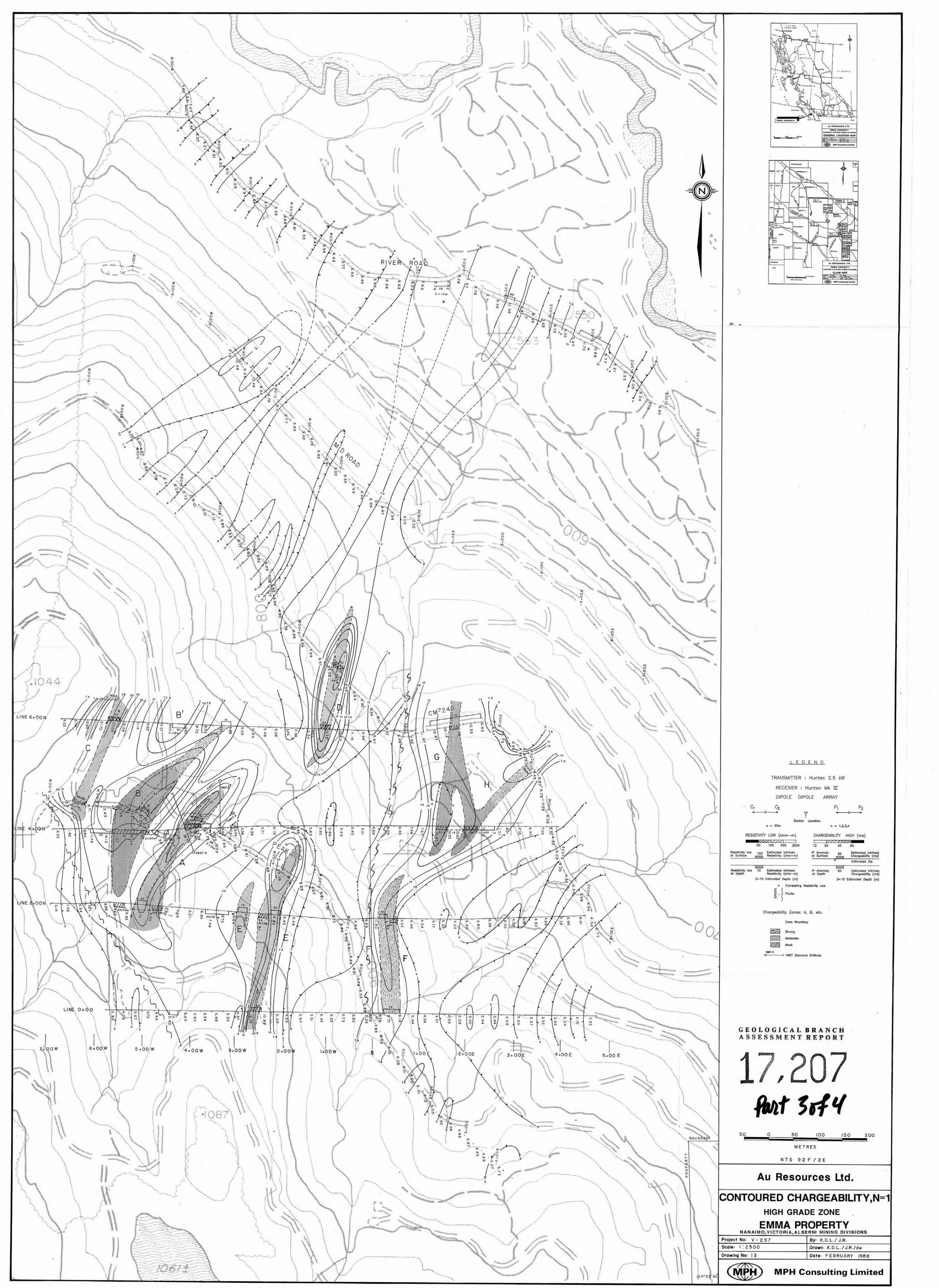
TRANSMITTER : Huntec 2.5 kW CONTACT
RECEIVER : Huntec Mk E
DIPOLE DIPOLE ARRAY
R P P R R E N T OHM-M R E S I S T I V I T Y Station Location
a = 25m n = 1,2,3,4
RESlSTlVlN LOW (ohm-m) CHARGEABILITY HIGH (ms)
/ / / I 1 I l / / / x ~ 20 100 500 2000 12 25 40 60
Resistivity low 00 Estimated Intrinsic 1P Anomaly 50 Estimated Intrinsic at Surface Is;wa Resistivity (ohm-m) at Surface Chargeability (ms)
f Estimated Dip
Resistivity low 70 Estimated Intrinsic 1P Anomaly 50 Estimated Intrinsic at Depth Resistivity (ohm-m) at Depth Chargeability (ms)
Z- 10 Estimated Depth (m) Z- 10 Estimated Depth (m)
* Correlating Resistivity Low I
f Fault
0 50 100
met res
AU RESOURCES LTD.
INDUCED POLARIZATION SURVEY RDS8
PEAK LAKE ZONE-EMMA PROPERTY T O T R L C H R R G E R B I L I T Y M T l M S E C l
e t 'I' \
MPH Consulting Limited
![ASSESSMENT GEOLOGICAL REPORT ON [AIRPHOTO FRACTURE …aris.empr.gov.bc.ca/ARISReports/11832.pdf · assessment geological report on [airphoto fracture density analysis] on the perk](https://img.dokumen.tips/doc/110x75/5accbba17f8b9a93268cd027/assessment-geological-report-on-airphoto-fracture-arisemprgovbccaarisreports11832pdfassessment.jpg)