Embed Size (px)
Citation preview

Novel functionalized and patterned
surfaces for cardiovascular applications
Dissertation
zur Erlangung des Grades
des Doktors der Ingenieurwissenschaften
der Naturwissenschaftlich-Technischen Fakultät
der Universität des Saarlandes
von
Romain Schieber
Saarbrücken, 2017


Tag des Kolloquiums: .......................
Dekan: .......................
Berichterstatter: .......................
………………..
………………..
Vorsitz: ………………..
Akad. Mitarbeiter: ………………..
10 November 2017
Prof. Dr. Guido Kickelbick
Prof. Dr.-Ing. Frank Mücklich
Priv.-Doz. Dr.-Ing. Guido Falk
Prof. Dr. José María Manero Planella
Dr. Marta Pegueroles Neyra
Prof. Dr. Javier Fernández Gongáles


I
Acknowledgments
Acknowledgements come first in the PhD thesis and, paradoxically, it is usually
the very last part we write. Why is that? In my case, it is because I was scared…
Obviously this task force us to remember all the people who helped and
brightened up the (long) 5 years PhD journey… Then, writing acknowledgments
is about realizing: all the beautiful persons I met, all the magic and intense
moments we shared, all the scientific terrific mountains we projected to climb and
were the firsts to summit. So I was scared to fully realize how unique was my
PhD… at the moment it ends…
In the first place, I would like to thank my supervisor Marta Pegueroles. I started
the PhD as a student and I leave it as a team-worker with so many scientific,
organizational, and above all, relational skills. Marta, this transformation is the
result of your professionalism and implication, thank you so much. In addition, I
thank you for your peaceful and comprehensive behavior during all the PhD. You
were my climbing rope and you made the mountains seem not that terrific ;-)
I would like to thank Prof. Maria Pau Ginebra and Prof. Xavier Gil for believing I
could be a good PhD student, for finding a way I could incorporate their BBT team
and for giving us the best conditions to investigate.
I had the chance to be part of the DocMASE programme and so I had a second
university in Saarbrucken. I would like to thank Prof. Dr. Ing. Frank Mücklich for
giving me the opportunity to work in his institute and for supervising this work. I
also thank Flavio, the coordinator of the DocMASE programme. That’s a huge
work and responsibility which you manage perfectly and with dedication. I will
always remember when I came to Saarbrucken for the first time without knowing
a word of German… You picked me up at the airport, brought me to the room you
booked for me, helped me to go through all the administrative tasks and
introduced me to your group of friends. One can’t expect more the first day in a
new country… So Flavio, thank you for your friendship!
Flavio is in the category of people who make your life easier through their
professionalism and their proactivity. In UPC I met many people in this category.
Txell and Noelia are the masters in this field. Thank you so much for being there

II
and finding a solution to every problem I had during my PhD. In this category are
included Montse, Trifon and Kim… Thank you to the three of you for finding time
in your crazy schedules, helping all the times I needed it and also for doing it with
enthusiasm and smiles. An unexpected person here is Maria-Angeles, she is not
a scientist but I can assure you that with her happiness, positiveness and her
energy she contributed significantly to our good research… So thank you so
much Maria-Angeles.
Writing these acknowledgments the word HELP is going through my mind again
and again… and I fully realize how lucky I was to grow with all this friendly
workmates who always helped and transmitted there tricks and knowledges…
Thanks to you I got the “climbing” techniques to go through the tricky sections of
the mountains. Thank you Montse, for asking always about my progress and
making me feel I did a great job. Thank you Cris, for your plasma and PLLA
expertise. Thank you Daniel, for helping during my first congress in Granada.
Thank you Cris, for your smile and your help even after 7 months of pregnancy.
Thank you Jordi, for answering with patience to all my silly biological questions.
Thank you to the enterprise-team (Miquel, Monica and Sergi) for transmitting
always good vibes. Thank you Joan Josep, for rescuing me from the deepest
crevasse I fell during PhD… the famous humid AFM crevasse! Thank you Carles
Boludo, for inspiring me, you are my scientific hero and on top of that, you always
find time to answer my technical or personal questions.
You don’t climb a mountain without some friends to share the experience or the
doubts with… In my case these close friends are so many that they got a team
named: Pollitos&Pollitas I thank all of you for creating and being part of the
Jungle Speed lunch therapy group… Most of the time you made me live this
experience so happily, and the rest of the time you helped me to see the
glass half-full. Thanks Erica, for sharing the same life balance. Thanks Erik for
introducing me most of the Barcelona social places I know. Thanks Mire for being
my PhD confident and for our summer library sessions. Thanks Robi for
discovering the PhD experience side-by-side, even if you did everything faster.
Thanks Quentin for your sarcastic vision of life and for all your administrative
tricks. Thanks Yas for your father attitude with me at the beginning. Thanks Gius
for being such an altruistic friend hidden behind this strange guy who preferred
to wash his desk than meeting me properly. Thanks Dani for being indulgent with

III
my disastrous birthday mistake. Thanks Dani2 for making me feel president, even
if it is only president of the Gluten-free PhD student association. Thanks Jose for
this unforgettable night in Stockholm. Thanks Nati for being my PhD mother
during my first PhD steps. Thanks Jing for your curiosity, your unique humor and
your inspiring progress in Spanish (I finally admit your Spanish is better than my
English ;-). Thanks Miquel for your little craziness we all would like to have and
for sharing all your “interesting” stories. Thanks Berni for becoming a true friend
in only 6 months and thanks for this little moment at the end of the Chrismas
Party. Thanks Newsha for your little craziness we all would like to have and
sharing all your “interesting” stories (it seems you fit with Miquel ;-).
Apart from the Pollitos&Pollitas team I had the pleasure to meet other beautiful
PhD students. Sara thank you so much for being the sun everywhere you go. Ana
I never met someone so generous, thanks for your always good words. Judit I
will always remember our first congress, how lost we were then and how big the
PhD seemed to us. David I remember that day when I wasn’t sure if it was
appropriate to send you my CV. I did it and as answer you convince me to join
the BBT and moreover, you convince the BBT to accept me. I will never thank
you enough for the opportunity you gave me that day. I learnt a lot with you.
Together with Yas you were my PhD fathers. Both of you made me a more
confident and tolerant person, I hope one day I could help you as much as you
helped me. Prya thank you for your contagious big smile. Mary thanks you for all
the experimental tricks you gave me and our mutual help friendship, it was really
useful for me.
The PhD and Marta gave me also the chance to transmit my experience and
knowledge to master students: Joe, Marc, Daniel, Isa, Yago y Helena. Thanks to
all of them for their works. Thanks Daniel for your implication and rigor, you will
be a high-level researcher. Thanks Isa for your enthusiasm to work with us, even
if we were not that lucky with the results. Thanks Yago for making the 3D stent
challenge possible with your own style and thank you for believing in Kim
deadlines ;-)
I was less time in Saarbrucken but there I had also the chance to meet beautiful
persons. Thanks Michael for guiding my research in my first stay and for all your
teaching on laser stuff. Thanks Shiqi for your unique friendship, for receiving me
at your place, for your Chinese food and for your laugh. Thanks Fede for being
IV
one of these persons who always ask how is everything going and try to find a
way to help. Our friendship and your help made my stays in Saarbrucken a nice
experience. Thanks Isabella for your funny vision of work and life. Thanks Seba
for helping and for our sport discussions.
I would also like to thanks all my friends, who obviously contributed to my PhD in
their own way. Particularly, I would like to thanks the ones living in Barcelona,
who suffered sometimes my changing mood. Thank you Miguelito, for always
being there to help me to escape from the PhD obsession. Thank you Vero and
Marc, for understanding the difference between a “PhD thesis by papers” and a
“PhD thesis by book” - or at least for trying to understand it
Every climber would tell you that a good technique is not enough to be a strong
climber… In other words “control is nothing without power”… And where does the
power come from? It is time to talk about my family… My mother did, do and will
do everything I need and at the same time she supports every decision I take…
I can’t thank you enough Mamoon! On the contrary, my father, has sometimes
difficulties to understand my strange and non-conformist decisions… but
eventually he always accepts it and even contributes to the success of my crazy
challenges… Le Pap thank you so much for all your unlimited support. Next
comes my brother Victor… or Vic… or Vicou... or also we like to call him the
perfect brother… because he always takes care of us… even if he is my little
brother… even if sometimes it could be too much: at the end of my first PhD year,
2013, I told him that I started to write my first scientific paper, since then every
time we talk I had the same question “Did you publish your first paper?”…
Fortunately I finally published this paper… in 2017. Thanks Vicou for all your
interest and support in all my projects. I do have another brother, Louis. He is not
as perfect as Vicou… He is more about chaos and surprise… But nobody can
ask more questions and enter dipper in your mind than he. His curiosity and his
interest in his relatives life are inspiring and make you feel your insignificant life
or your little project are so valuable and useful. Thanks Loulou for your complicity
and for being my talisman.
As you have seen, all the way up to that terrific scientific mountains I have been
very lucky to meet so many beautiful people, to believe in the robustness of my
rope, to learn the technique from my colleagues, to be rescued by experts, to
share the experience with my friends, to use my natural power… But without my

V
climbing partner I would probably not have summited these huge mountains… or
even worst… Carmencita, she is the one on the other side of the rope since 10
years now and I feel so confident since then that I never untied my knot… I feel
so confident since then that I decided to climb mountains that seemed
unreachable before… the ones who met me before can attest that at that time my
English and my Spanish sucked, I didn’t want to live outside France, I had no
professional ambition and even less the intention to do PhD… So Carmen, for
being at my side, for inspiring me, for supporting me in all my projects and for
making me a better person I thank you infinitely. I love you.

VI

VII
Short Abstract
English
Nowadays, cardiovascular diseases are mainly treated by implantation of a
metallic or polymeric mesh, called stent, which maintains the artery widely open.
This technique shows very good clinical results, however, it exists non-negligible
cases of in-stent restenosis (ISR) and late stent thrombosis (LST) during the first
year after stent implantation. These complications are mainly due to a delayed
recovery of the endothelium after stent implantation, which also involves smooth
muscle cells (SMCs) over-proliferation and platelet aggregation. Surface
nano-topography, biofunctionalization or chemical features may be applied to
increase endothelial cells (ECs) adhesion and/or migration, and to control platelet
agglomeration.
The overall aim of this thesis was to obtain novel modified surfaces for stents
implants with the ability to induce accelerated reendothelialization and controlled
platelet aggregation in order to avoid ISR and LST. On CoCr alloy, as the gold
standard material for bare metal stents (BMSs), two different strategies were
evaluated, generation of linear patterns by direct laser interference patterning
(DLIP) and, immobilization of biomolecules. Cellular studies provided evidence
of the potential of DLIP topographies and YIGSR biofunctionalization to foster
endothelialization without enhancement of platelet adhesion, which will be of high
importance when designing new stents. On poly(L-lactic acid) (PLLA), as a
material for bioresorbable stents (BRSs), endothelialization was enhanced by
surface functionalization with plasma treatment and cutinase enzyme hydrolysis.
German Heutzutage werden vaskuläre Erkrankungen hauptsächlich durch Implantation
eines metallischen oder polymeren Netzes, genannt Stent, behandelt, welcher
vormals verengte Arterien weit geöffnet hält. Diese Technik zeigt bereits sehr
gute klinische Ergebnisse. Allerdings existieren auch nicht zu vernachlässigende

VIII
Fälle von In-Stent Restenose (ISR) und späten Stentthrombosen (LST) im ersten
Jahr nach Implantation des Stents. Diese Komplikationen entstehen
hauptsächlich aufgrund einer verzögerten Erholung der Endothele nach
Einsetzen des Stents, sowie durch übermäßiges Wachstums der vaskulären
glatten Muskelzellen (SMCs) und einer Thrombozytenaggregation.
Das Gesamtziel dieser Arbeit war es, neuartige modifizierte Oberflächen für
Stentimplantate zu entwickeln, die die Reendothelialisierung beschleunigen und
eine Thrombozytenaggregation verringern, um ISR und LST vorzubeugen. Auf
einer CoCr-Legierung, dem Gold-Standard-Material für unbeschichtete
Metallstents (BMSs), wurden zwei unterschiedliche Strategien verfolgt; einerseits
die Erzeugung linearer Muster durch direkte Laserinterferenzstrukturierung
(DLIP) und Immobilisierung von Biomolekülen. Zellstudien belegen das Potential
von DLIP-Topographien und YIGSR-Biofunktionalisierung, um die
Endothelialisierung ohne Erhöhung der Thrombozytenadhäsion zu fördern, was
von großer Bedeutung bei der Entwicklung neuer Stents sein wird. Auf Poly (L-
Milchsäure) (PLLA) als Material für bioresorbierbare Stents (BRSs) wurde die
Endothelialisierung durch Oberflächenfunktionalisierung mit einer
Plasmabehandlung und mit Cutinase-Enzym-Hydrolyse verbessert.

IX

X
Abstract
Nowadays, cardiovascular diseases are mainly treated by implantation of a
metallic or polymeric mesh, called stent, which maintains the artery widely open.
This technique shows very good clinical results, however, it exists non-negligible
cases of in-stent restenosis (ISR) and late stent thrombosis (LST) during the first
year after stent implantation. These complications are mainly due to a delayed
recovery of the endothelium after stent implantation, which also involves smooth
muscle cells (SMCs) over-proliferation and platelets aggregation. Stent surface
modification to modulate a specific cell lineage response has not been
comprehensively explored. In particular, surface nano-topography,
biofunctionalization or chemical features may be applied to increase endothelial
cells (ECs) adhesion and/or migration, and to control platelet agglomeration.
The overall aim of this thesis was to obtain novel modified surfaces for stents
implants with the ability to induce accelerated reendothelialization and controlled
platelet aggregation in order to avoid ISR and LST. On CoCr alloy, as the gold
standard material for bare metal stents (BMSs), two different strategies were
evaluated, generation of linear patterns by direct laser interference patterning
(DLIP) and, immobilization of biomolecules. On poly(L-lactic acid) (PLLA), as a
material for bioresorbable stents (BRSs), endothelialization was enhanced by
surface functionalization with NaOH etching, plasma treatment and cutinase
enzyme hydrolysis.
CoCr alloy surfaces were successfully modified with a linear pattern of different
periodicities and depths. Afterwards, Arg-Gly-Asp (RGD) and
Tyr-Ile-Gly-Ser-Arg (YIGSR) peptides were covalently immobilized to the
surfaces through silanization. Early ECs adhesion was improved on the
peptide-functionalized surfaces, especially for YIGSR compared to RGD.
High-depth nano-patterned surfaces generated ECs alignment within the
topographical lines and enhanced ECs migration. Noteworthy, the combined use
of both strategies, topography and biofunctionalization, synergistically
accelerated the ECs migration and proliferation. Also, platelet adhesion and
aggregation decreased in all patterned surfaces compared to smooth CoCr

XI
probably due to changes in wettability and oxide layer characteristics. Cellular
studies provided evidence of the potential of DLIP topographies and YIGSR
biofunctionalization to foster endothelialization without enhancement of platelet
adhesion, which will be of high importance when designing new stents.
Concerning polymeric biodegradable materials, PLLA films were obtained by
solvent-casting in chloroform and, oxygen plasma, NaOH solution or cutinase
enzyme treatments were used to functionalize the PLLA films and create surface
hydroxyl and carboxyl groups without compromising biocompatibility. A higher
amount of functional groups and an improved ECs adhesion was observed by
oxygen plasma and cutinase enzyme hydrolysis compared to NaOH etching.
Plasma or cutinase enzyme functionalized PLLA films presented a degradation
rate similar to a peripheral commercial stent. Finally, 3D-printed PLLA BRSs were
obtained by solvent-cast direct write technique. Consequently, the combined use
of the solvent-cast direct write technique and plasma or enzyme functionalization
holds a great potential to fabricate 3D-printed PLLA BRSs with the capacity to
accelerate the surface endothelialization.
Overall, the present thesis offers a comprehensive view of the effectiveness of
modifying CoCr alloys and PLLA films with specific topographies or
functionalization strategies to enhance surface endothelialization while
preventing restenosis and thrombosis.

XII
Zusammenfassung
Heutzutage werden vaskuläre Erkrankungen hauptsächlich durch Implantation
eines metallischen oder polymeren Netzes, genannt Stent, behandelt, welcher
vormals verengte Arterien weit geöffnet hält. Diese Technik zeigt bereits sehr
gute klinische Ergebnisse. Allerdings existieren auch nicht zu vernachlässigende
Fälle von In-Stent Restenose (ISR) und späten Stentthrombosen (LST) im ersten
Jahr nach Implantation des Stents. Diese Komplikationen entstehen
hauptsächlich aufgrund einer verzögerten Erholung der Endothele nach
Einsetzen des Stents, sowie durch übermäßiges Wachstums der vaskulären
glatten Muskelzellen (SMCs) und einer Thrombozytenaggregation.
Modifikationen der Stent-Oberfläche, um die Interaktion mit spezifischen Zellypen
zu kontrollieren, sind noch nicht umfassend erforscht. Insbesondere können
Oberflächen-Nano-Topographie, Biofunktionalisierung oder chemische
Modifizierungen angewendet werden, um die Adhäsion und / oder Migration der
Endothelzellen (ECs) zu erhöhen und die Agglomeration von Blutplättchen
niedrig zu halten.
Das Gesamtziel dieser Arbeit war es, neuartige modifizierte Oberflächen für
Stentimplantate zu entwickeln, die die Reendothelialisierung beschleunigen und
eine Thrombozytenaggregation verringern, um ISR und LST vorzubeugen. Auf
einer CoCr-Legierung, dem Gold-Standard-Material für unbeschichtete
Metallstents (BMSs), wurden zwei unterschiedliche Strategien verfolgt; einerseits
die Erzeugung linearer Muster durch direkte Laserinterferenzstrukturierung
(DLIP) und Immobilisierung von Biomolekülen. Auf Poly (L-Milchsäure) (PLLA)
als Material für bioresorbierbare Stents (BRSs) wurde die Endothelialisierung
durch Oberflächenfunktionalisierung mit NaOH-Ätzen, mit einer
Plasmabehandlung und mit Cutinase-Enzym-Hydrolyse verbessert.
Zum anderen wurden Oberflächen einer CoCr-Legierung erfolgreich mit einem
Linien-Muster unterschiedlicher Periodizität und Tiefe modifiziert. Anschließend
wurden Arg-Gly-Asp (RGD) und Tyr-lle-Gly-Ser-Arg (YIGSR) Peptide durch
Silanisierung kovalent an den Oberflächen immobilisiert. Die frühe ECs-Adhäsion
wurde auf den Peptid-funktionalisierten Oberflächen verbessert, insbesondere

XIII
für YIGSR im Vergleich zu RGD. Nanostrukturierte Oberflächen mit großer Tiefe
erzeugten eine ECs-Ausrichtung innerhalb der topographischen Linien und
förderten die EC-Migration und -Proliferation. Bemerkenswerterweise wurden
diese synergetisch durch Kombination der zwei Strategien, Topographie und
Biofunktionalisierung, beschleunigt. Auch die Thrombozytenadhäsion und –
aggregation sanken in allen strukturierten Oberflächen verglichen mit glattem
CoCr, möglicherweise auf Grund von Veränderungen der Benetzbarkeit und der
Oxidschichteigenschaften. Zellstudien belegen das Potential von DLIP-
Topographien und YIGSR-Biofunktionalisierung, um die Endothelialisierung
ohne Erhöhung der Thrombozytenadhäsion zu fördern, was von großer
Bedeutung bei der Entwicklung neuer Stents sein wird.
In Bezug auf polymere biologisch abbaubaren Materialien wurden PLLA-
Schichten durch Solvent-Casting in Chloroform hergestellt. Sauerstoffplasma,
NaOh-Lösemittel oder Cutinase-Enzym-Behandlungen wurden genutzt, um die
PLLA-Schichten zu funktionalisieren und Oberflächen-Hydroxylgruppen und -
Carboxylgruppen herzustellen, ohne die Biokompatibilität zu beeinträchtigen. Im
Vergleich zu NaOH-Ätzen wurden durch Sauerstoffplasma und durch Cutinase-
Enzym-Hydrolyse eine höhere Anzahl an funktionellen Gruppen und eine
verbesserte ECs-Adhäsion festgestellt. Plasma- oder Cutinase-Enzym-
funktionalisierte PLLA-Schichten zeigten eine ähnliche Degradation wie ein
peripher, kommerzieller Stent. Abschließend wurden 3D-gedruckte PLLA-BRSs
durch Solvent-Cast Direct Writing hergestellt. Folglich bietet die Kombination aus
Solvent-Cast Direct Writing und Plasma- oder Enzymfunktionalisierung ein
großes Potenzial, 3D-gedruckte PLLA-BRSs mit beschleunigter
Oberflächenendothelialisierung herzustellen.
Insgesamt bietet die vorliegende Arbeit einen umfassenden Überblick über die
Effektivität der Modifizierung von CoCr-Legierung und PLLA-Filmen mit
spezifischen Topographien oder Funktionalisierungsstrategien zur Verbesserung
der Oberflächenendothelialisierung bei gleichzeitiger Vermeidung von
Restenose und Thrombose.

XIV
Resumen
Actualmente las enfermedades cardiovasculares están principalmente tratadas
por implantación de una malla metálica o polimérica, llamada stent, que mantiene
la arteria abierta. Esta técnica presenta muy buenos resultados clínicos, sin
embargo, existen casos de reestenosis intra-stent (ISR) y trombosis tardia del
stent (LST) durante el año que sigue la implantación. Estas complicaciones están
principalmente debidas a una reparación demasiado lenta del endotelio después
de la implantación del stent; que también implica una sobre-proliferación de
células musculares lisas y una agregación de plaquetas. La modificación de la
superficie del stent para generar una respuesta celular específica no ha sido
explorada en profundidad. Particularmente, nano-topografía, biofuncionalización
o modificaciones químicas pueden ser aplicadas para incrementar la adhesión y
la migración de las células endoteliales (ECs), y para controlar la aglomeración
de las plaquetas.
El objetivo global de esta tesis es de obtener nuevas superficies modificadas
para stent implantes con la habilidad de inducir una endotelización acelerada y
de controlar la agregación de plaquetas. Sobre CoCr, material de referencia para
los stent metálicos desnudos (BMSs), dos estrategias diferentes fueron
evaluadas, la creación de patrones lineales por la técnica Direct Laser
Interference Patterning (DLIP) y, la inmovilización de biomoléculas. Sobre acido
L-poliláctico (PLLA), como material para stent biodegradables (BRSs), la
endotelización fue activada por funcionalización de la superficie vía tratamientos
con NaOH, plasma o enzima cutinasa.
Patrones lineales de diferentes periodicidades y profundidades fueron obtenidos
sobre superficies de CoCr. Después, los péptidos Arg-Gly-Asp (RGD) y
Tyr-Ile-Gly-Ser-Arg (YIGSR) fueron enganchados covalentemente por
silanización sobre les superficies de CoCr lisas y con patrones. La adhesión de
ECs aumento sobre las superficies funcionalizadas, especialmente con el
péptido YIGSR comparado con el RGD. Las superficies con patrones profundos
generaron un alineamiento de las ECs con la dirección de las líneas del patrón y
aceleraron la migración de esas mismas células. Además, el uso combinado de
XV
esas dos estrategias, topografía y biofuncionalización, acelero sinérgicamente la
migración y la proliferación de las ECs. Por fin, la adhesión y la agregación de
plaquetas disminuyo sobre todas las superficies con patrones comparado con
las superficies de CoCr lisas, efecto causado por los cambios de la capa de óxido
introducido por la técnica DLIP. Los estudios celulares demuestran el potencial
de las topografías DLIP y de la biofuncionalización para mejorar la endotelización
sin aumentar la adhesión de plaquetas, lo que puede ser interesante a la hora
de diseñar nuevos stents.
En cuanto a los stent biodegradables, películas de PLLA fueron obtenidas por la
técnica de solvent-casting y, plasma de oxígeno, solución de NaOH o enzima
cutinasa fueron utilizados para funcionalizar esas películas de PLLA y, así crear
grupos hidroxilos y carboxilos en superficie sin comprometer la
biocompatibilidad. Plasma de oxígeno y enzyma cutinasa generaron más grupos
funcionales y mejoraron más la adhesión de ECs comparado con el tratamiento
de NaOH. Además, las superficies de PLLA modificadas por plasma o enzima
presentaron una degradación similar a la degradación de un stent comercial.
Finalmente, BRSs de PLLA fueron obtenidos por impresión 3D vía la técnica de
solvent-cast direct write. Consecuentemente, el uso combinado de esa técnica y
de la funcionalización por plasma o enzima presenta un gran potencial para
fabricar BRSs de PLLA impreso en 3D con la capacidad de acelerar la
endotelización de la superficie.
En conclusión, esta tesis demuestra la efectividad de modificar las superficies de
CoCr o PLLA con topografías específicas o con estrategias de funcionalización
para mejorar la endotelización y paralelamente reducir los riesgos de trombosis
y reestenosis.

XVI

XVII
Publication and other contributions
Publication
R. Schieber, F. Lasserre, M. Hans, M. Fernández-yagüe, M. Díaz-ricart, G. Escolar,
M. Ginebra, F. Mücklich, M. Pegueroles, Direct Laser Interference Patterning of CoCr
Alloy Surfaces to Control Endothelial Cell and Platelet Response for Cardiovascular
Applications, Adv. Healthc. Mater. (2017). doi:10.1002/adhm.201700327.
Conference contributions
R. Schieber, S. Raymond, F. Mücklich, M. Pegueroles, 3D printed bioresorbable stents
by solvent-cast direct-write technique, 2th Annual Conference European Society for
Biomaterials, 4th – 7th September 2017, Athens (Greece) – Oral presentation.
R. Schieber, D. Moreno, C. Mas Moruno, F.J. Gil, F. Mücklich, M. Pegueroles,
Biofunctionalization of patterned PLLA surfaces with RGD, REDV and YIGSR peptides to
promote endothelial cells adhesion and migration, 2016 TERMIS-EU Conference, 28th
June – 1st July 2016, Uppsala (Sweden) – Poster presentation.
R. Schieber, D. Moreno, C. Mas Moruno, F.J. Gil, F. Mücklich, M. Pegueroles,
Biofunctionalization of patterned PLLA surfaces with cell adhesive peptides to promote
endothelial cells adhesion, XXXVIII Congreso de la Sociedad Ibérica de Biomecánica y
Biomateriales, 6th – 8th November 2015, Barcelona (Spain) – Poster presentation.
D. Moreno, R. Schieber, F.J. Gil, M. Pegueroles, Functionalization of patterned PLLA
surfaces with cell adhesive peptides to promote endothelial cells adhesion and
migration, I Seminar of Nanosurfaces: Advanced Processing and Characterization – II
International Seminar on Biomaterials, Biomechanics and Regenerative Medicine,
16th - 18th September 2015, Medellin (Colombia) – Poster presentation.

XVIII
R. Schieber, D. Moreno, C. Mas Moruno, M. Hans, M. Díaz-ricart, G. Escolar, F.J. Gil, F.
Mücklich, M. Pegueroles, Surface endothelialization and non-thrombogenic strategies
for cardiovascular applications, 8th EEIGM International Conference on Advanced
Materials Research, 11th – 13th June 2015, Valencia (Spain) – Oral presentation.
R. Schieber, M. Fernández-Yagüe, M. Hans, M. Díaz-ricart, G. Escolar, F.J. Gil, F. Mücklich,
M. Pegueroles, Endothelization and thrombogenicity response of CoCr alloy nano depth
patterns for cardiovascular stents, 26th Annual Conference European Society for
Biomaterials, 31st august – 3rd september 2014, Liverpool (United Kingdom) – Poster
presentation.
R. Schieber, M. Fernández-Yagüe, M. Hans, F.J. Gil, F. Mücklich, M. Pegueroles,
Patterned CoCr alloy by Laser Interference Surface Structuring for cardiovascular
applications, XIII Congreso Nacional de Materiales, 18th – 20th June 2014, Barcelona
(Spain) – Oral presentation.
R. Schieber, M. Hans, M. Fernández-Yagüe, F.J. Gil, F. Mücklich, M. Pegueroles, Laser
interference surface structuring of CoCr alloy to endothelize cardiovascular stents, XXXVI
Congreso de la Sociedad Iberica de Biomecenica y Biomateriales (SIBB), 25th – 27th
october 2013, Granada (Spain) – Oral presentation.
Scholarship
Pre-doctoral grant Erasmus Mundus Joint Doctorates – European Joint Doctoral
Programme in Materials Science and Engineering (DocMASE), European Comission
from European Union. October 2012 – September 2016.

XIX
Curriculum Vitae
SCHIEBER Romain Born in Paris, France, February 1985
Academic Qualifications
Oct.2012-present PhD double degree. First university: Biomaterials, Biomechanics and Tissue Engineering (BBT), Universitat Politècnica de Catalunya, Barcelona, Spain. Second University: Chair of Functional Materials, Saarland University, Saarbrücken, Germany. Fellowship funded by ERASMUS MUNDUS DocMASE Program
2004-2011 Combined Bachelor and Master degree, a 5-year studies in engineering in the Materials Science Department at the National Institute of Applied Science (INSA). High level sport section (7 years of studies instead of 5 years to allow an intense sport practice).
2010-2011 Last year of INSA in an exchange program in the engineering school of the Universidad Nacional de La Plata (UNLP), Argentine.
2004 A-levels with summa cum laude, majors in Maths, Physics, Chemistry and Biology at the Tivoli High School, France.
Professional Experience
2012 Investigation engineer at Electricité de France (E.D.F.). Subject: Aging of high-voltage direct current cables.
Abril-September2011 Industrial Internship, Research Assistant for Safran in the Laboratoire des Composites ThermoStructuraux (LCTS), Bordeaux, France
Aug.2010-Mars2011 Laboratory Internship in Laboratorio de Aeronáutica de la Universidad de La Plata, Argentina.

XX

XXI
Table of Contents
Chapter I: Introduction ........................................................................................... 1
1. Endothelialization ................................................................................................. 2
1.1. Definition ...................................................................................................... 2
1.2. Artery structure ............................................................................................ 2
1.3. Cardiovascular diseases ................................................................................ 3
1.4. Stents ............................................................................................................ 4
1.4.1. Stent properties ........................................................................................ 6
1.4.2. Stent evolution ......................................................................................... 7
1.4.3. Stent next generation ............................................................................... 8
2. Biomaterials for stents ....................................................................................... 10
2.1. Cobalt-chromium (CoCr) alloy for stents fabrication ...................................... 10
2.1.1. Metals for stents ..................................................................................... 10
2.1.2. CoCr alloys .............................................................................................. 11
2.2. Poly(L-lactic acid) (PLLA) for stents fabrication .......................................... 11
2.2.1. Biodegradable materials for stents ........................................................ 11
2.2.2. PLLA ........................................................................................................ 16
3. Surface modification ........................................................................................... 17
3.1. Topography ................................................................................................. 18
3.1.1. Cell response to topography .................................................................. 18
3.1.2. Direct Laser Interference Patterning (DLIP) ........................................... 19
3.2. Chemistry .................................................................................................... 20
3.3. Biofunctionalization .................................................................................... 22
3.3.1. Cell response to biofunctionalization ..................................................... 23
3.3.2. Design of biofunctional molecules ......................................................... 26
3.3.3. Immobilization strategies ....................................................................... 27
4. 3D printing for stent fabrication ......................................................................... 29
References ...................................................................................................................... 31
Chapter II: Aims and scope of the work ........................................................ 47

XXII
Chapter III: Direct Laser Interference Patterning of CoCr Alloy
Surfaces to Control Endothelial Cell and Platelet Response for
Cardiovascular Applications ............................................................................... 51
1. Introduction ........................................................................................................ 52
2. Materials and methods ...................................................................................... 52
2.1. Materials ..................................................................................................... 52
2.2. DLIP technique ............................................................................................ 53
2.3. Physico-chemical characterization ............................................................. 54
2.3.1. Surface topography ................................................................................ 54
2.3.2. Chemical characterization ...................................................................... 55
2.3.3. Surface wettability .................................................................................. 56
2.4. Biological characterization ......................................................................... 56
2.4.1. Blood perfusion assay ............................................................................. 56
2.4.2. Cell adhesion .......................................................................................... 57
2.4.3. Cell migration.......................................................................................... 58
2.5. Statistical analysis ....................................................................................... 59
3. Results and discussion ........................................................................................ 59
3.1. Physico-chemical characterization ............................................................. 59
3.1.1. Surface topography ................................................................................ 59
3.1.2. Chemical characterization ...................................................................... 63
3.1.3. Surface wettability .................................................................................. 67
3.2. Biological characterization ......................................................................... 68
3.2.1. Platelet adhesion and aggregation ......................................................... 68
3.2.2. Cell adhesion .......................................................................................... 71
3.2.3. Cell migration.......................................................................................... 73
4. Conclusions ......................................................................................................... 75
References ...................................................................................................................... 76

XXIII
Chapter IV: Synergistic effect of surface biofunctionalization and
nanopatterning of CoCr alloy for cardiovascular applications:
endothelial cell adhesion, migration and proliferation ......................... 83
1. Introduction ........................................................................................................ 84
2. Materials and methods ...................................................................................... 84
2.1. CoCr alloy surfaces ..................................................................................... 84
2.2. DLIP technique ............................................................................................ 85
2.3. Functionalization of CoCr surfaces ............................................................. 87
2.3.1. Solid-phase peptide synthesis ................................................................ 87
2.3.2. Protocol of immobilization ..................................................................... 87
2.4. Physico-chemical characterization of the patterned surfaces ................... 88
2.5. Physico-chemical characterization of the biofunctionalized surfaces ....... 89
2.6. Biological characterization ......................................................................... 90
2.6.1. Endothelial cells ...................................................................................... 90
2.6.2. Cell adhesion .......................................................................................... 90
2.6.3. Wound healing migration study ............................................................. 91
2.6.4. Cells proliferation ................................................................................... 91
2.7. Statistical analysis ....................................................................................... 92
3. Results and discussion ........................................................................................ 92
3.1. Fabrication of linear patterned CoCr and surface characterization ........... 92
3.2. Biofunctionalization of CoCr and surface characterization ........................ 96
3.1. HUVECs adhesion and alignment ............................................................. 101
3.2. HUVECs migration .................................................................................... 104
3.3. HUVECs proliferation ................................................................................ 105
4. Conclusions ....................................................................................................... 107
References .................................................................................................................... 108

XXIV
Chapter V: Solvent-cast poly(L-lactic acid) surfaces functionalized by
sodium hydroxide etching, oxygen plasma or cutinase enzyme
hydrolysis for 3D-printed bioresorbable stent fabrication ................. 115
1. Introduction ...................................................................................................... 116
2. Materials and methods .................................................................................... 117
2.1. Materials ................................................................................................... 117
2.2. PLLA films by solvent casting .................................................................... 117
2.3. PLLA films surface activation .................................................................... 118
2.4. PLLA films characterization ...................................................................... 118
2.5. Surface characterization ........................................................................... 120
2.6. PLLA films degradation ............................................................................. 121
2.7. HUVECs adhesion ..................................................................................... 121
2.8. 3D-printed BRS obtained by solvent-cast direct write technique ............ 122
2.9. Statistical analysis ..................................................................................... 122
3. Results and discussion ...................................................................................... 122
3.1. PLLA film properties ................................................................................. 123
3.2. Surface characterization ........................................................................... 125
3.3. Degradation of PLLA films ........................................................................ 128
3.4. HUVECs adhesion ..................................................................................... 131
3.5. BRS obtained by solvent-cast direct write technique .............................. 133
3. Conclusions ....................................................................................................... 133
References .................................................................................................................... 135
Chapter VI: General conclusions .................................................................... 141

XXV

XXVI

XXVII
Glossary of terms
BMS bare metal stent
BRS bioresorbable stent
CoCr cobalt-chromium
CPTES 3-chloropropyltriethoxysilane
DES drug eluting stent
DLIP direct laser interference patterning
E Young’s modulus
EC endothelial cell
FDA food and drug administration
FIM first-in-human study
HUVEC human umbilical vein endothelial cell
IRS in-stent restenosis
LST late stent thrombosis
NaOH sodium hydroxide
PLLA poly(L-lactic acid)
RGD (Arg-Gly-Asp)
SMC smooth muscle cell
UTS ultimate tensile strength
YIGSR (Tyr-Ile-Gly-Ser-Arg)

XXVIII

Chapter I: Introduction
0
Table of Contents
Chapter I: Introduction ..................................................................................................... 1
1. Endothelialization ................................................................................................. 2
1.1. Definition ...................................................................................................... 2
1.2. Artery structure ............................................................................................ 2
1.3. Cardiovascular diseases ................................................................................ 3
1.4. Stents ............................................................................................................ 4
1.4.1. Stent properties ........................................................................................ 6
1.4.2. Stent evolution ......................................................................................... 7
1.4.3. Stent next generation ............................................................................... 8
2. Biomaterials for stents ....................................................................................... 10
2.1. Cobalt-chromium (CoCr) alloy for stents fabrication ...................................... 10
2.1.1. Metals for stents ..................................................................................... 10
2.1.2. CoCr alloys .............................................................................................. 11
2.2. Poly(L-lactic acid) (PLLA) for stents fabrication .......................................... 11
2.2.1. Biodegradable materials for stents ........................................................ 11
2.2.2. PLLA ........................................................................................................ 15
3. Surface modification ........................................................................................... 16
3.1. Topography ................................................................................................. 17
3.1.1. Cell response to topography .................................................................. 17
3.1.2. Direct Laser Interference Patterning (DLIP) ........................................... 18
3.2. Chemistry .................................................................................................... 20
3.3. Biofunctionalization .................................................................................... 21
3.3.1. Cell response to biofunctionalization ..................................................... 22
3.3.2. Design of biofunctional molecules ......................................................... 26
3.3.3. Immobilization strategies ....................................................................... 27
4. 3D printing for stent fabrication ......................................................................... 29
References ...................................................................................................................... 31

Chapter I: Introduction
1
Chapter I: Introduction
Cardiovascular diseases is one of the leading causes of mortality and morbidity
in the world 1. According to the World Health Organization (WHO), 17.3 million
people died from cardiovascular related diseases in 2008, and this number is
projected to rise to an estimated 23.6 million by 2030 2. Age and bad habits like
smoking, sedentary lifestyles, or fat diet are a major factor in cardiovascular
problems.
Cardiac events like heart attack or cerebrovascular accidents are mainly caused
by the formation of an artherosclerotic plaque in the artery wall which eventually
blocks the blood flow preventing the delivery of oxygen and nutrients to the body.
The main cardiovascular disease is atherosclerosis, which consists in an
accumulation of lipids and cholesterol in the artery wall leading to a reduction of
the artery inner section, also called stenosis. The evolution and rupture of the
atherosclerotic plaque and the endothelium leads to the formation of thrombus,
also called thrombosis.
Nowadays, cardiovascular diseases are mainly treated by implantation of a
metallic or polymeric mesh, called stent, which maintains the artery widely open 3.
This technique shows very good clinical results however, it exists non-negligible
cases of in-stent restenosis (ISR) and late stent thrombosis (LST) during the first
year after stent implantation 4. These complications are mainly due to a delayed
endothelium reconstruction after removal of the endothelium during stent
implantation which also involves SMC over-proliferation and a platelet
aggregation. The cardiovascular research is focused in improving stents by
optimizing stent characteristics: design, material, drug delivery, surface
coatings… However, few studies have been done on stent surface modification
in order to modulate a specific cell lineage response.
The overall aim of this thesis was to obtain novel modified surfaces for stents
implants with the ability to induce accelerated reendothelization and controlled

Chapter I: Introduction
2
platelet aggregation in order to avoid ISR and LST. In the present introduction,
the scientific context is explained, as well as the medical problem, the stent
solution, the stent biomaterials and the possible surface modifications to reach
the presented aim.
1. Endothelialization
1.1. Definition
Endothelialization is the formation of endothelial tissue. A healthy endothelium,
the inner layer of the artery in contact with blood, is composed of a monolayer of
endothelial cells (ECs) and it has antithrombogenic properties, among others.
Consequently, endothelialization is an extremely important process expected to
occur as soon as possible when the endothelium is damaged.
1.2. Artery structure
Arteries are blood vessels that carry oxygenated blood away from the heart to
supply the body with oxygen. The native artery is an extremely complex
multi-layered tissue composed of many proteins and cell types, each playing a
crucial role in the mechanical and biological behavior of the structure. An artery
is composed of three major layers as seen on Figure I.1:
• Tunica intima or Endothelium, is the innermost layer of the vessel wall
and it contains elastic and connective tissue. A monolayer of endothelial
cells is in contact with the hollow internal cavity in which the blood flows,
the lumen. As the cellular interface between the circulating blood and the
vessel wall, the endothelium main function is to avoid blood coagulation
through the production of molecules with antithrombotic properties,
including nitric oxide, prostacyclin, tissue plasminogen activator,
thrombomodulin, heparin-like molecules, and tissue factor pathway
inhibitor 5. Moreover, the healthy endothelium permeability is also crucial
to provide a barrier between the artery lumen and surrounding tissue, to
keep the blood inside the artery and, at the same time, allows the
exchange of nutrients with the interior of the tunica media 6,7.
• Tunica media, is composed of elastic tissue and several layers of smooth
muscle cells (SMCs) in a matrix of collagen types I and III, elastin and
proteoglycans. In the largest arteries, as the aorta, the amount of elastic

Chapter I: Introduction
3
tissue is very considerable. The muscle fiber cells are arranged in 5 to
7 layers of circular and longitudinal SMCs of about 50 μm length 8,9.
• Tunica adventitia or Tunica externa, is the most external layer
composed of connective tissue with fibroblasts, microvascular networks
and randomly arranged collagen type I 10,11.
Figure I.1: Schematic views of the functional artery with its three major layers: endothelium, tunica media and tunica externa.
1.3. Cardiovascular diseases
Cardiovascular diseases are mostly caused by atherosclerosis, which is a
physiologic phenomenon beginning at the embryonic stage and evolving with
arteries ageing. This disease is related to genetic predisposition and lifestyle.
Adhesion of circulating monocytes to the surface of the endothelium appears to
be an early event in the development of atherosclerotic lesions. Next, they
insinuate through the endothelium and are transformed into macrophages, which
ingest lipids and form fatty deposits 12. Meanwhile, a number of molecular factors,
like platelet adhesion, generate proliferation of SMCs in the intima. Monocytes,
lipids, platelets, SMCs, and fibrous connective tissues form an inflammatory
plaque called atheroma (Figure I.2). Finally, atherosclerosis can generate two
main complications:

Chapter I: Introduction
4
Stenosis, which is the long-term evolution of atherosclerosis due to a slow
growth of the atheroma plaque leading to final obstruction of the artery.
Thrombosis, which is a quick and acute complication corresponding to the
rupture of the endothelium and/or the atheroma plaque. This rupture exposes
the collagen of tunica intima connective tissues to the bloodstream 13. On
contact with collagen, platelets become activated. Platelet activation induce
several thrombogenic event like platelet adhesion and aggregation 14. Finally,
a thrombus is formed which can obstruct the artery or detach and obstruct
another vessel.
Figure I.2: Schematic representation of a portion of artery in a healthy state, with atherosclerosis disease progress at different stages, resulting in stenosis and/or thrombosis.
1.4. Stents
In the 70’ coronary diseases were healed by Coronary Bypass Graft Surgery
consisting in removing the occluded section of the artery and replacing it with a
healthy conduct by performing a coronary bypass. But this open chest surgery is
an invasive method which is therefore heavy and complicated. Also, as it requires
the chest wall to be cracked open, it can easily lead to infections.
The advent of percutaneous transluminal coronary angioplasty in 1977
provided a fundamental change in the treatment of coronary artery diseases 1.
Angioplasty is the technique of mechanically widening narrowed or obstructed
arteries. Percutaneous surgery, also called “non-invasive” surgery means that
the surgery is done through the skin instead of doing open chest surgery. It
consists in doing a small incision in the patient’s skin at the level of an artery.

Chapter I: Introduction
5
Then a catheter is inserted through the incision in the vascular system. These
catheters are hollow flexible tubes for insertion into a body vessel to distend a
passageway for other medical tools. Unlike the traditional open heart surgery, the
heart does not need to be arrested during the procedure.
Non-invasive surgery has been used since 40 years with the first human coronary
balloon angioplasty performed intra-operatively in 1977 by Gruentzig, Myler and
Hanna in San Francisco 1. It consisted in the enlargement of the stenosed
coronary artery thanks to a balloon inflated in the atherosclerosed artery
portion (Figure I.3).
Rapidly the coronary balloon angioplasty will be replaced by the use of coronary
stent. Stent are mesh implanted in the diseased arteries to hold it open to a
predetermined diameter (Figure I.3). In 1982, appeared the first patent, by Hans
Wallsten, concerning a self-expandable metallic braided stent called Wallstent
(Boston Scientific, United States) 15. The first implantation of the Wallstent in
human coronary position is done by J. Puel in 1986 15.
Figure I.3: Non-invasive coronary surgery on a stenosed artery: angioplasty on the left and stent implantation on the right.
Vascular stents represent today one of the main application of percutaneous
technology. Its popularity arises due to its less invasive nature (compared to
surgical alternatives) and its better clinical outcome (compared to balloon
angioplasty) 16,17. The use of stents for all applications has dramatically increased

Chapter I: Introduction
6
since their approval by the United States Food and Drug Administration (FDA) in
1994, largely as a result of therapeutic and technological advances. In 2010, in
the United States, an estimated of 492 000 patients underwent percutaneous
transluminal coronary angioplasty in the United States and the stent market reach
$5 billion per year 18.
1.4.1. Stent properties
Endovascular stents are expandable meshes that range from 6 to 60 mm in
length and from 2 to 10 mm in diameter, most commonly made from stainless
steel, chromium-cobalt alloy, the nickel-titanium alloy Nitinol, although tantalum
19, platinum 19, plastic 20, and biodegradable materials 21,22 have also been used.
In a compressed state the stent is mounted on a catheter and threaded through
the vascular tree to a site of narrowing. The stent is next enlarged in diameter
approximately 50%, either by a spring-like recoil into their naturally expanded
shape (e.g. Nitinol) or by plastic deformation under the influence of a cylindrical
balloon inflated within the stent to 8-20 atmospheres of pressure. Once the
catheter is withdrawn the stent is left within the artery.
As the stent’s main function is to compress the atheroma, stent should present
high mechanical properties as high Young’s modulus (E) or high ultimate tensile
strength (UTS) (Table I.1). As for all implant, stent materials should be
biocompatible and corrosion resistant in body conditions.
Table I.1: Stent required characteristics and associated biomaterials properties. E: Young modulus; UTS: Ultimate tensile strength
Stent necessary properties
Description Associated
biomaterials properties
High scaffolding Ability to provide strong mechanical support
to the vessel wall High E
High expansion ratio The material should undergo sufficient
expansion and conform to the vessel wall High UTS
Excellent corrosion resistance
Ability to prevent corrosion induced by formation of oxide films
No prejudicial corrosion in body conditions
Good biocompatibility
Material must be biocompatible so as to not elicit an adverse reaction from the body
Low % of complications in the clinical studies
Thrombo-resistivity
The material should be blood compatible and not encourage platelet adhesion and
deposition
Low % of thrombosis in the clinical studies
Inexpensive to manufacture
The material should be cost-effective to purchase
Cheap and easy-to process

Chapter I: Introduction
7
1.4.2. Stent evolution
1.4.2.1. Bare metal stent (BMS)
BMS, which is an expandable tube of metallic mesh, was introduced in 1986.
BMS provides a mechanical scaffold to widely open the narrowed artery, to
prevent artery elastic recoil and negative remodeling. However, besides crushing
the atheroma plaque, stent deployment destroys partially and disrupts the
endothelium 23, triggering an over-exposure of collagen, SMCs, fibronectin and
laminin to the blood flow; and consequently generating a cascade of
thrombogenic events allowing the platelets to aggregate. This is the initial point
of the thrombus formation, creating a wall injury that presents clot formation
where the macrophages get attracted due to the metallic foreign surface. Finally,
it occurs an uncontrolled proliferation and migration of SMCs to the intima leading
to the re-narrowing of arteries called in-stent restenosis (ISR) 19,24,25. As a
consequence of this cascade of biological events, it can be observed early
thrombosis, 1 to 3 % the 10 first days 15 and mostly ISR during the first year after
stent implantation 3 (Figure I.4). However, when compared with balloon
angioplasty, BMS significantly reduces the ISR rate from 50 %
to 20 – 30 % 3,16,21.
1.4.2.2. Drug Eluting Stent (DES)
In addition to acting as a vascular scaffold, stents soon evolved to become drug
delivery systems in the form of DES. DESs are composed of a metallic stent
covered by a polymer which contains a pharmacologic agent. They allow a local
drug release to the artery wall. These drugs include anti-inflammatory,
anti-proliferative and anti-migratory agents. The goal of DES technology is to
minimize vascular inflammation and SMCs proliferation, in order to reduce ISR.
Early trials of different DESs demonstrated markedly reduced rates of ISR from
20 – 30 % to 5 – 10 % 26–29, heralding the DES revolution that followed. Although
DESs reduce ISR, the liberation of anti-proliferative drugs also induce a delayed
reendothelialization and, consequently, increased the risk of LST occurring more
than one year after stent implantation 30–32. Some studies, identified a rate of late
stent thrombosis (LST) as high as 9.4% 33. Consequently, continuation of
dual-anti-platelet therapy is required for one or more years after DES placement.

Chapter I: Introduction
8
1.4.2.3. Bioresorbable Stent (BRS)
The interest of a BRS is to have a temporary stent that bioabsorbs with time
allowing the vessel to recover its natural shape and function. BRS are an
alternative for the currently-used permanent cardiovascular stents as it has been
shown that the effect of stents is temporary and limited to a period of 6 to 12
months after intervention during which arterial remodeling and healing occur 34.
The advantages of BRS in front of DES are the stent fully degradation in 12 to 24
months, among others:
A reduction in adverse events such as LST 35,36.
The return of vessel vasomotion, adaptive shear stress, late luminal
enlargement, and late expansive remodeling 37.
A reduction in bleeding complications and consequently no requirement
for long-term dual antiplatelet therapy.
Elimination of the concern that some patients have of having an implant in
their bodies for the rest of their lives 38.
It’s worth mentioning that actual research on BRS is developing stents with a
polymeric coating containing pharmacologic agents.
Figure I.4: Complications after stent implantation. (a) Section of artery just after stent implantation. (b) ISR due to stent implantation. (c) Different stages of stent thrombosis.
1.4.3. Stent next generation
BMS, DES and BRS main characteristics are summarized in Figure I.5. Fully
biodegradable stent seems to be the ideal compromise to, first, induce the artery

Chapter I: Introduction
9
to recover its structure and functionality and, secondly, to avoid ISR or LST
generated by the presence of permanent BMS or DES. However, BRS are very
new devices and the Food and Drug Administration (FDA) waited to July 2016 to
approve the first BRS for coronary artery, the Absorb GT1 (Abbott,
United States). At April 2017 Abbot restricted the use of Absorb GT1 in Europe
due to some cardiac events related to the implantation of this BRS. Moreover, in
tortuous section of the artery, there is higher mechanical stress due to blood flow
modification. In these portions of arteries it would be risky to use BRS due to its
mechanical properties deterioration with biodegradation. Thus, permanent stent
will continue being implanted for several years or decades. Generally, BMSs
have a higher incidence of ISR whereas DESs have a higher frequency of LST.
Then, the surgeon select one of the two according to the cardiovascular disease
specificity. In conclusion, we believe that in the short and medium term no one
will be discarded, stent implantation will be done with BMS, DES or BRS
according to the medical cases.
Figure I.5: Stent generations and its mains characteristics. Modified from 39.

Chapter I: Introduction
10
2. Biomaterials for stents
2.1. Cobalt-chromium (CoCr) alloy for stents fabrication
2.1.1. Metals for stents
As the main objective of the BMS was to counter the negative effects of the
balloon angioplasty, it should address properties such as rigidity for maintenance
of dilatation and resistance to elastic recoil, elasticity or plasticity for expansion,
corrosion resistance, radiopacity and radial strength 15.
Therefore, from the viewpoint of mechanical properties, it is natural that stents
are made of metals. The metallic materials most currently used for coronary
stents are 316L stainless steel (SS), cobalt chromium (CoCr) alloys and
titanium alloys 40–42.
Stainless Steel
SS is a steel alloy with a minimum of 12-13 mass % of Cr. The main reason for
the use of SSs is the good balance between strength (E ≈ 193 GPa) and
elongation, which facilitates the manufacture of the stent, the plasticity for the
balloon expansion, and the maintenance of geometry to resist the elastic recoil
of blood vessels. Most metal stents are made of austenitic SS 316L. SSs do not
corrode in an oxygen-containing atmosphere, but they corrode locally and
sometimes form pits in chloride solutions as found in some body fluids. Type
316L SS shows pitting and crevice corrosion when implanted in the human body
43,44.
Nickel-titanium alloy (Nitinol)
The nickel-titanium (NiTi) alloy, also known as Nitinol, is a metal alloy with an
approximately equiatomic composition of titanium (Ti) and nickel (Ni)
(49-51 mol % of Ni) and shows unique mechanical properties such as shape
memory, and superelasticity. Shape memory effect gives NiTi the ability to be
deformed at one temperature, and then return to its original shape when being
heated to its transformation temperature. Superelasticity occurs at specific
temperature and allows the material to recover to its original shape after an
apparent plastic deformation as soon as the stress is removed. Because of these
unique properties, the NiTi alloy is used to fabricate guide wires, stents,
orthodontic arch wires, and endodontic reamers, among others. The SMART

Chapter I: Introduction
11
stent (Cordis, United States) and Radius stent (SciMED Live System,
United States) are examples of NiTi BMSs currently used. However, the NiTi alloy
usually exhibits crevice corrosion and pitting, and it corrodes during service in
aortic endografts, where pitting and craters are observed on the alloy 45.
2.1.2. CoCr alloys
CoCr alloys show high strength, toughness, castability, corrosion resistance, and
wear resistance. CoCr alloy was initially used as a cast alloy because working it
is difficult due to its high hardness. The Wallstent, is made of Elgiloy, a
40Co-20Cr-15Ni-7Mo-Mn alloy that was developed as a heat-resistant alloy. For
biomedical use, cast Co–Cr–Mo alloys, commonly known as Vitallium alloys
family, resist pitting and crevice corrosion. Because of the carbide in its structure,
CoCr alloys have excellent wear resistance and are used for sliding parts of
artificial joints.
Wrought CoCr alloys, which are used for stents, were designed to avoid cast
defects in cast CoCr alloys. The strength and elongation of wrought CoCr alloys,
which increase with heat treatment and cold working, are as high as those of SS.
The corrosion resistance of the wrought CoCr alloy is lower than that of cast CoCr
alloy, but higher than that of SS. Therefore, wrought CoCr alloy is used for guide
wires, clips, orthodontic arch wires, and catheters.
Mainly, for the corrosion resistance properties, it has been decided to select CoCr
alloy ASTM F90 to study metallic surface modification for cardiovascular
applications. This alloy is a wrought 51Co-20Cr-15W-10Ni alloy for surgical
implant applications. It has a Young’s modulus of 210 GPa and a unique ability
to resist corrosion in very severe environments 46–48.
2.2. Poly(L-lactic acid) (PLLA) for stents fabrication
2.2.1. Biodegradable materials for stents
DESs are made of a metallic core, generally CoCr alloy, stainless steel or Nitinol,
covered by a polymeric coating containing drugs. Permanent polymer were used
for the first DES generation 21,49–51. Next, biodegradables polymers coating were
developed to reduce the long-term risks associated with the presence of a
permanent polymer 16. These materials offer the attractive combination of
controlled drug elution in parallel with biodegradation of the polymer into inert

Chapter I: Introduction
12
monomers. Table I.2 shows DESs biodegradable materials used as coating, its
mechanical properties and its observed clinical advantages and disadvantages.
Few biodegradable polymers have been used for DESs coating:
poly(lactic acid) (PLA), poly(lactic-co-glycolic acid) (PLGA),
polycaprolactone (PLC) and polyvinylpyrrolidone (PVP). Among them, only DESs
with a PLA have been approved by the European Union (EU) with a Conformité
Européenne marquage (CE mark). All the other DESs are under First-In-Man
(FIM) or recent clinical studies.
The polymers use for the SIMPLE II coating, a copolymer of PLC and PVP,
induced non satisfactory clinical results and cannot be use for BRS because of
its low mechanicals properties. The copolymers used for the Supralimus and
Infinium coating was synthesized especially for this application and its properties
are confidential.
All the PLA coating show better clinical results than BMSs, including few LST and
a better endothelial recovery. Finally, PLA have the highest mechanical
properties, suggesting it could be also the best candidate for BRSs.

Table I.2: Mechanical properties and clinical results of biodegradable polymers used as coatings for DESs. PLC: polycaprolactone; PVP: polyvinylpyrrolidone; PLGA: poly(lactic-co-glycolic acid); PLA: poly(lactic acid); E: Youngs modulus; UTS: ultimate tensile strength; Tg: glass-transition temperature; FIM: first-in-man study; late loss: reduction of the lumen diameter in the 6 months after stent implantation.
DESs Polymers State of investigation Clinical advantages Clinical disadvantages Mechanical properties Ref.
Simple II PLC / PVP FIM ; not approved Average rate of in-stent
angiographic restenosis and average
late loss
PLC properties:
E = 30-200 MPa;
UTS = 20-40 MPa
Tg = -61ºC
3,52
Nevo stent PLGA Recent clinical studies;
not approved
Satisfactory binary ISR rates and
in-stent late loss
E = 1-4 GPa;
UTS = 41,4-55,2 MPa
53,54
Biomatrix stent PLA CE mark Few LST events; near complete
endothelial recovery (>95%)
UTS= 15-150MPa;
E = 2,7-4,14 GPa
53,55
NOBORI PLA CE mark Significantly better endothelial
recovery than BMSs
UTS= 15-150MPa;
E = 2,7-4,14 GPa
53,56
Axxess PLA CE mark At 6-month follow-up, in-stent
late loss was 0.09 mm
80% and 42% of patients,
respectively, required 2 or 3
additional stents to cover the lesion
UTS= 15-150MPa;
E = 2,7-4,14 GPa
53,57
XTENT PLA CE mark CoCr structure; modular design
made up of multiple 6-mm
segments that were interdigitated
UTS= 15-150MPa;
E = 2,7-4,14 GPa
53,57
JACTAX PLA Recent clinical studies;
not approved
UTS= 15-150MPa;
E = 2,7-4,14 GPa
53,57
Supralimus and
Infinnium stent Copolymer
(confidential)
FIM ; not approved Rate of in-stent angiographic
restenosis of 0.0%; low late loss
50,53,58
Synergy stent PLGA Recent clinical studies;
not approved
target lesion failure at 30 days E = 1-4 GPa;
UTS = 41,4-55,2 MPa
53,57

Table I.3: Mechanical and degradation properties and clinical results of biodegradable polymers used for BRSs. PLLA: poly(L-lactic acid); PDLLA: poly(D,L-lactic acid); E: Young’s modulus; UTS: ultimate tensile strength; FIM: first-in-man study; late loss: reduction of the lumen diameter in the 6 months after stent implantation; MACE: major adverse cardiac events; TLR: target lesion revascularization.
BRSs Polymers Stat of investigation Clinical advantages Clinical disadvantages Properties Ref.
IGAKI-
TAMAI
stent
PLLA Long human studies
(more than 10 years);
CE mark for
peripheral arteries
since 2007
Non-drug eluting (PLLA without
drug); a low complication rate;
survival rates free from death, cardiac
death, MACE, and TLR were 89%,
98%, 60%, and 76%, respectively.
Concern has arisen about
the ability to apply heat, to
self-expand the stent,
without causing possible
necrosis of the artery wall.
UTS= 15-150MPa;
E = 2,7-4,14 GPa;
Degradable in 18-24 month.
53,57,59
Paclitaxel
-eluting
PLLA
PLLA Non-human studies;
not approved
reduced proliferation and stenosis after
vascular intervention
UTS= 15-150MPa;
E = 2,7-4,14 GPa
53,60
ABSORB
GT1
PLLA (and a
PDLLA coating
with evrolimus
inside)
CE mark for coronary
arteries since 2011;
FDA approval in
2016
reduced in-stent late loss and a low
MACE rate of 4.4%; few acute vessel
recoil; no LST has been observed out
to 3 years follow-up
UTS= 15-150MPa;
E = 2,7-4,14 GPa
Degradable in 24 month;
radial support during 3 months
35,36,53
REVA
stent
Tyrosine
polycarbonate
FIM; not approved Improve acute recoil; minimal vessel
shrinkage at follow-up
Mechanical failure led to a
higher than anticipated rate
of target lesion
revascularization
Radio opaque; degradable in
36 month; radial force
comparable to a BMS
61,62
IDEAL
BDS
Poly(anhydride
ester) (salicylic
acid)
FIM; not approved Successful results in pig coronary
arteries; in human trials, absence of
acute or chronic recoil; reduction in
inflammation compared to BMS.
Insufficient neointimal
inhibition due to inadequate
drug dosing and very quick
elution of Sirolimus.
Degradable in 12 months;
radial strength greater than
BMS; resistant to gamma
radiation
19,63

Chapter I: Introduction
15
Table I.3 shows developed BRS, being all of them approved or under clinical trial.
Tyrosine polycarbonate, used for the REVA stent, got correct FIM study results.
However, it presents mechanicals failure associated with a too long polymer
degradation and too recent studies. For these reasons it is preferable not to use
tyrosine polycarbonate.
Poly(anhydride ester) (salicylic acid), used for the IDEAL BRS, shows successful
results in human trials, particularly an absence of acute or chronic recoil and a
reduce inflammation compared to BMSs have been reported. This is the result of
its high radial strength and its appropriate degradation rate. Also, the presence
of salicylic acid in the polymer backbone permit to release drug without
introducing drug inside the polymer. Insufficient neointimal inhibition is the only
defect of this biodegradable polymer.
2.2.2. PLLA
PLLA and poly(D-lactic acid) (PDLA) are two different stereosisomers of PLA. For
BRSs, PLLA has been chosen mainly for its higher crystallinity (about 37%) and,
therefore, its higher mechanical properties (E = 3 GPa and UTS = 15-150 MPa;
Table I.4).
A semi-crystalline polymer (PLLA) is obtained from L-lactide.The special interest
on PLLA to fabricate BRS is probably due to the fact that it is the biodegradable
polymer with the highest mechanical properties 64. Also, among all biodegradable
polymers, it has the slowest degradation rate 65, and, when obtained with a high
molecular weight, it has been shown to take up to 5 years to be completely
resorbed in vivo 66,67. PLA undergoes thermal degradation at temperatures
above 200ºC mainly by hydrolysis, however, lactide reformation, oxidative main
chain scission, and inter- or intra-molecular transesterification reactions also
occur 68. PLA degradation is dependent on time, temperature, low-molecular-
weight impurities, and catalyst concentration 68. Also, PLLA used for BRSs have
shown satisfactory clinical results, like particularly few major adverse cardiac
events (MACE) and few thrombosis complication. Among them, the ABSORB
GT1 is approved by the UE and the FDA for coronary arteries.
To conclude, PLLA has already been used in many DESs and BRSs, it has all
the mechanical and degradation properties necessary for the application and, it
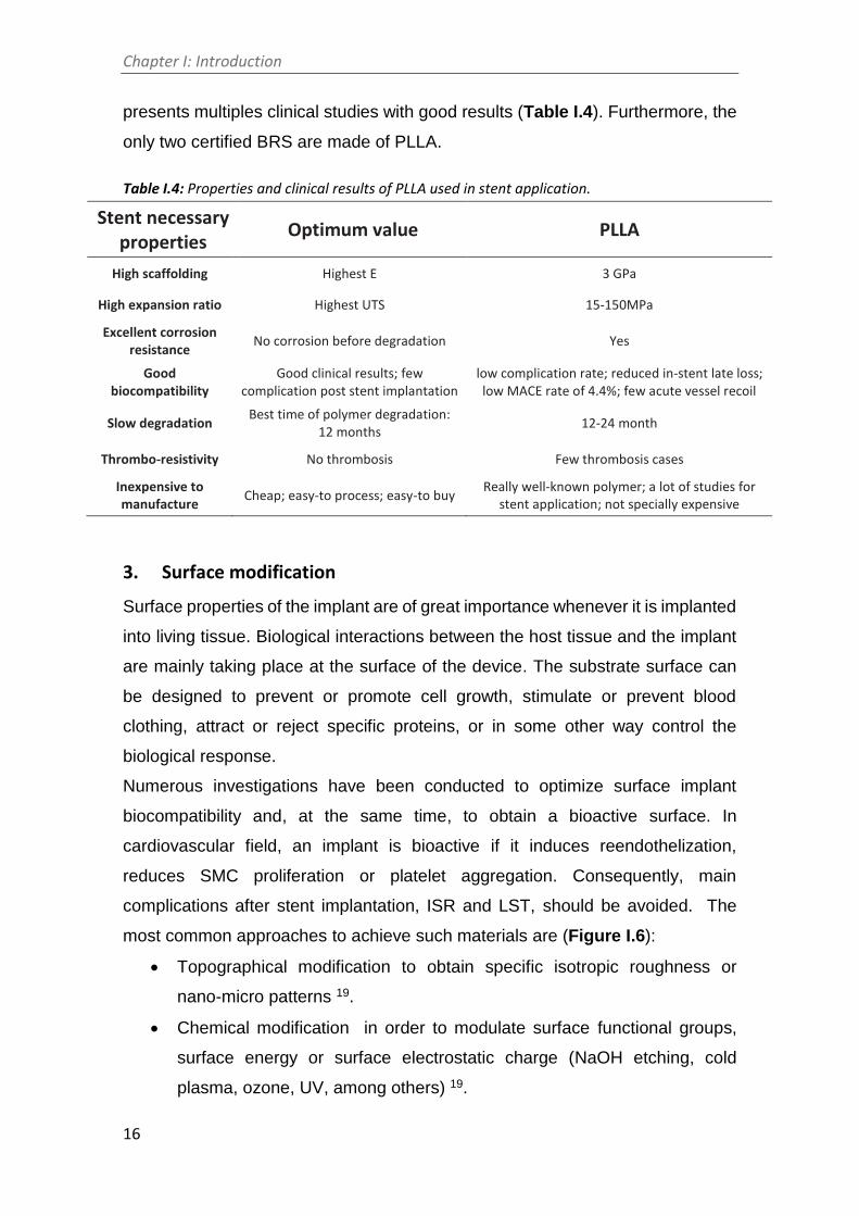
Chapter I: Introduction
16
presents multiples clinical studies with good results (Table I.4). Furthermore, the
only two certified BRS are made of PLLA.
Table I.4: Properties and clinical results of PLLA used in stent application.
Stent necessary properties
Optimum value PLLA
High scaffolding Highest E 3 GPa
High expansion ratio Highest UTS 15-150MPa
Excellent corrosion resistance
No corrosion before degradation Yes
Good biocompatibility
Good clinical results; few complication post stent implantation
low complication rate; reduced in-stent late loss; low MACE rate of 4.4%; few acute vessel recoil
Slow degradation Best time of polymer degradation:
12 months 12-24 month
Thrombo-resistivity No thrombosis Few thrombosis cases
Inexpensive to manufacture
Cheap; easy-to process; easy-to buy Really well-known polymer; a lot of studies for
stent application; not specially expensive
3. Surface modification
Surface properties of the implant are of great importance whenever it is implanted
into living tissue. Biological interactions between the host tissue and the implant
are mainly taking place at the surface of the device. The substrate surface can
be designed to prevent or promote cell growth, stimulate or prevent blood
clothing, attract or reject specific proteins, or in some other way control the
biological response.
Numerous investigations have been conducted to optimize surface implant
biocompatibility and, at the same time, to obtain a bioactive surface. In
cardiovascular field, an implant is bioactive if it induces reendothelization,
reduces SMC proliferation or platelet aggregation. Consequently, main
complications after stent implantation, ISR and LST, should be avoided. The
most common approaches to achieve such materials are (Figure I.6):
Topographical modification to obtain specific isotropic roughness or
nano-micro patterns 19.
Chemical modification in order to modulate surface functional groups,
surface energy or surface electrostatic charge (NaOH etching, cold
plasma, ozone, UV, among others) 19.

Chapter I: Introduction
17
Biofunctionalization of surface by immobilization of specific biomolecules
which facilitates or activates a cascade of biological events and,
eventually regenerates or replaces functioning tissue 69.
Figure I.6: Examples of various physical, chemical, and biofunctionalization techniques to enhance hemocompatibility. Biofunctionalized surfaces interact with cell surface receptors, which are integrins. Whereas physiochemical modification can influence cell-material interactions through charge, topography, and attractive/repulsive forces due to hydrophobic and hydrophilic interactions 69.
3.1. Topography
3.1.1. Cell response to topography
Surface roughness and texture of implants is known to influence biological
response. Topography on the micro- and nano-metric scale is an important
physical property, which influences protein adsorption, platelet adhesion,
thrombogenicity, and cell behaviour. Originally, studies have suggested that a
rough surface is more prone to thrombogenicity 70–72 and thus, surface treatments
were essential to obtain a contamination-free and smooth surface for stent
material applications. To obtain such stent surfaces various surface treatments
are used, including mechanical polishing, electropolishing, ultrasonic cleaning,
chemical etching and degreasing, as well as low-pressure plasma etching 73.
Electropolishing possesses several compelling advantages that render it the
most popular surface treatment method for polishing stents surfaces 74.
Nowadays, the literature presents rather conflicting information about the exact
role of topographical manipulation to platelet response, with a study reporting no

Chapter I: Introduction
18
significant differences between platelet activation on smooth or nanoscale
topographical surfaces 75. Other studies have shown that specific low roughness
surfaces or nano-depth pattern can induce an antithrombogenic effect. For
example, Chen et al. 76 showed that nano-micro patterned surfaces of TiO2
presented lower platelet adhesion than on flat surfaces indicating that platelet
activation may be dependent on the dimension of surface features as well as their
aspect ratio. Certain nanostructured materials can have inherent
antithrombogenic properties. If, in addition, high aspect ratio features are
incorporated in their design then, platelet contact will be mainly limited to the tips
of the nanopillars (or ‘hilltops’) and therefore, activation could be minimized 77,78.
Meanwhile, several studies observed the behaviour of ECs on different
substrates with different patterning structures such as grooves, pillars, pits and
ridges at the nano- and micro-meter range 79–82. Numerous in vitro work
demonstrated the importance of grooves on alignment of ECs promoting parallel
migration, especially under low and normal stress conditions 79–82. Biela et al. 80
showed that 10 µm width grooves induced ECs alignment and directed migration
on silicon Si. Whereas, another study demonstrated a preferential orientation and
elongation of ECs on anisotropically ordered ridges larger than 800 nm on a
polyurethane substrate 81. Thus, it is no real consensus on determining which
topographical features influence a certain cell lineage adhesion.
3.1.2. Direct Laser Interference Patterning (DLIP)
A range of physical techniques are actually applied to modify the surface
topography of vascular graft materials: metallographic grinding, plasma etching,
photolithographic etching, UV lithography, among others 50,83,84. Most of the
employed processing techniques involve multiple preparation procedures
incorporating coating and/or patterning steps. On the contrary, the Direct Laser
Interference Patterning (DLIP) technique requires one single processing step
and can be applied to a wide range of materials 85. The principle is based on the
unique intensity pattern generated by interfering laser beams (Figure I.7), which
show periodicities from the submicron range up to 50 µm. By photothermal
interaction with the irradiated surfaces, the periodic patterns translate to the
actual spacing factor of the afterwards topographically and/or chemically
structured surface.

Chapter I: Introduction
19
Figure I.7: Direct Laser Interference Patterning (DLIP) technique: (a) Beam configuration and
principle of DLIP for a two beams set-up; (b) The calculated intensity distribution in case of two
equal, interfering beams shows a line-like pattern with cos2(α) profile 86.
Also, DLIP presents the possibility to obtain depth pattern lower than 20 nm which
have never been elaborated for cardiovascular application. Finally, this technique
has never been used in the cardiovascular field. Therefore, this PhD thesis
proposes to use DLIP technique on CoCr alloy in order to obtain nano-micro
patterned structure. To promote endothelial cells alignment and migration, lineal
pattern will be design (Figure I.8). In addition, to study the influence of pattern
depth on platelet adhesion, different pattern-depth will be fabricated.
Figure I.8: Schematic representation of CoCr surfaces modification by DLIP technique and the expected effect on ECs and platelets response.

Chapter I: Introduction
20
3.2. Chemistry
Chemical methods are based on chemical reactions occurring at the surface of
the material producing modifications of the chemical composition, structure,
and/or stoichiometry of native materials surface.
Modifying surface topography, as described in the previous section, influences
also important chemical properties. For instance, rougher topography increases
surface electrostatic charge and surface energy. Both properties have a strong
impact on the interactions of the material with the surrounding biological system.
That is the reason why all the techniques introduced in the previous section have
been also used to modify surface chemical composition, and eventually to create
chemical patterns 86.
Other approaches to increase surface energy and hydrophilicity that produced
promising in vitro and in vivo outcomes have been recently developed, such as
cold plasma treatment 87–89 (Figure I.9), ultraviolet irradiation 90, sodium
hydroxide (NaOH) etching 91,92 or ozone irradiation 93.
Figure I.9: Scheme of polymer surface functionalization by plasma processes using air as gas for plasma generation 105.

Chapter I: Introduction
21
For metallic alloys, chemical etching consists in the immersion of the samples
into different acid (e.g. HCl, H2SO4, HNO3 and HF) 94 or alkaline (e.g. NaOH) 8,95
chemical solutions. Depending on the chemical solution, the modified material
can exhibit different reactivity. Thus, it is possible to induce the formation of a
protecting layer by passivation or the dissolution and the flattening of surface
defects. CoCr alloy reacts with alkaline solutions improving the formation of – OH
groups on the CoCr surface due to the high pH solution.
Also, enzymatic treatments have been proposed and successfully used for the
surface modification of natural and synthetic polymers 96,97. For polyesters, such
as PLLA, the hydrolysis of the ester bond by applying cutinase enzymes generate
new hydroxyl and carboxyl groups onto the surface, which have been used to
direct drug loading 98, to create superhydrophobic surfaces 99 or to bind serum
albumin in order to increase biocompatibility 96. Different activation treatments
work differently onto PLLA surfaces, while NaOH treatment is an aggressive
non-selective hydrolysis that generates etching 100,101, oxygen plasma acts more
superficially (< 1 µm) and according to treatment conditions generates unspecific
functionalization, hydrolysis and eventually etching 102,103 and, cutinase enzyme
allows a selective hydrolysis of the ester bonds of the outermost surface layers
of the polymer generating only hydroxyl and carboxyl groups 100,104.
3.3. Biofunctionalization
The described methods to modify surface properties of implants do not change
intrinsic bioinert chemical characteristics of the surfaces and, hence, are limited
in improving their biological response. The strategies that aim on modifying the
biochemical nature of the surface in order to create specific interactions with
specific cells can be more promising and are introduced in the following sections.
Biofunctionalization of surfaces is a strategic research field, which relies on the
use of biology tools to create biomimetic surfaces to incorporate biologically
active molecules to generate specific responses 106.
The success of an implant relies on the establishment of strong and long lasting
biochemical and mechanical interactions between the biomaterial and the
surrounding endothelial tissue. The initial adhesion events of ECs on bioactive
surfaces involve two distinct steps. An initial phase, where cells rapidly attach to
the materials via physicochemical interactions (i.e. electrostatic forces,

Chapter I: Introduction
22
hydrophobic interactions, hydrogen bonds, and van der Wall forces). And a
second adhesive phase, in which cell adhesive proteins interact with each other
and promote signal transduction and activation of long-term adhesion processes
including cell proliferation and differentiation 107.
Integrins represent the most prominent family of cell adhesion receptors, and
have crucial roles in cellular processes that require cell attachment or growth of
tissue. In particular, integrins mediate cell-cell contacts and cell adhesion to
proteins of the extracellular matrix (ECM) 108,109. ECs express cell-surface
integrins such as β1 108,110,111, which have the capacity to recognize and bind to
ECM proteins. ECs ECM is composed of collagen 1, laminin, heparin and fibrin
112. Modification of implant materials with biomolecules derived from ECM
components represents thus, an attractive concept for biomaterial scientists to
promote integrin-mediated binding of ECs and improve reendothelization. In the
next sections, this approach will be described.
3.3.1. Cell response to biofunctionalization
Early studies investigated the use of natural, full-length ECM proteins to coat
implant surfaces. These investigations included the use of collagen, heparin 113–
116, laminin 117 and fibrin 118. Although this approach was proven to be successful
to enhance cell adhesion on the functionalized surfaces, the use of proteins bears
several disadvantages that precluded their widespread use and application. In
the first place, proteins are enzymatically unstable and long-term functionality
within the body would not be possible. In addition, protein production is usually
performed in other organisms, and therefore its use in humans is associated with
an increased risk of infections and adverse immune responses. Also, proteins are
costly to produce in large amounts and their manipulation, modification and
characterization for surface coating purposes is a demanding task. Last but not
least, the conformation of the protein and/or the orientation of the bioactive motifs
might be influenced by the physicochemical properties of the surface resulting in
non-favorable presentations to support cell adhesion 119,120.
Most of these drawbacks may be overcomed by using short ECM-derived
peptides that contain the cell adhesive motifs, usually of only a few amino acids,
present in the natural proteins (Figure I.10). Linear peptides are readily available
using current solid phase peptide synthesis methodologies, and can be produced

Chapter I: Introduction
23
in large quantities at a very low cost. They are easily characterized and
functionalized for coating purposes. Moreover, due to lower steric requirements,
they could be immobilized with higher density on solid supports compared to
native ECM proteins. They are also much less sensitive to pH and temperature
changes than full-length proteins. Finally, short linear peptides are not
immunogenic and their use is exempt from infection risks.
The RGD sequence (Arg-Gly-Asp) represents by far the most extensively
studied cell adhesion motif used to functionalize surfaces and implant materials
in order to stimulate cell attachment and adhesion, enhance cell migration and
influence cell proliferation and differentiation 119. Since its discovery in 1984 as
the minimal cell binding sequence in fibronectin 121, this tripeptide has also been
identified in many other ECM proteins with cell adhesive properties. Thus,
besides fibronectin, the RGD sequence was detected in fibrinogen, collagen type
I, vitronectin, von Willebrand factor, osteopontin, laminin, tenascin and
thrombospondin 122–124. Of the 24 known integrins, 8 receptor subtypes have
been described to recognize and bind the RGD motif: αvβ1, αvβ3, αvβ5, αvβ6, αvβ8,
α5β1, α8β1 and αIIbβ3 108,109. As said before, ECs are known to express β1 integrins.
Thus, it seems plausible that functionalization of surfaces with short RGD motifs
might help to promote EC adhesion and reendothelization. The literature is full of
examples of enhanced EC adhesion on matrices coated with short RGD peptides
69,125,126. However, due to the presence of RGD receptors in most integrins, RGD
motif binds with most integrins. Consequently, ECs adhesion to RGD is not
specific and it is probable that RGD motif induces SMCs adhesion and platelets
adhesion.
Various ECM peptide sequences, which have been determined to influence
specifically EC behavior, have been isolated and grafted on materials to enhance
biological properties, for example, Arg-Glu-Asp-Val (REDV),
Pro-His-Ser-Arg-Asn (PHSRN) and Gly-Arg-Gly-Asp-Ser-Pro (GRGDSP) from
fibronectin, laminin-derived recognition sequences, Ile-Lys-Leu-Leu-Ile (IKLLI),
Ile-Lys-Val-Ala-Val (IKVAV), Leu-Arg-Glu (LRE), Pro-Asp-Ser-Gly-Arg (PDSGR),
and Tyr-Ile-Gly-Ser-Arg (YIGSR), and collagen type I derived sequence,
Asp-Gly-Glu-Ala (DGEA). In particular, the laminin-derived peptide sequence
YIGSR has demonstrated improved EC attachment, spreading and resistance to
shear stress 127–129. Recently, Taite et al. incorporated polyethylene glycol (PEG)

Chapter I: Introduction
24
and the YIGSR peptide into the backbone of polyurethane to improve the long-
term patency of polyurethane vascular grafts 130. The incorporation of PEG
reduced platelet adhesion in vitro. Additionally, the incorporation of YIGSR
peptide encouraged EC adhesion and SMCs did not adhere to YIGSR-containing
polyurethane.

Chapter I: Introduction
25
Figure I.10: Strategies to biofunctionalize material surfaces with biomolecules. A) Adsorption of naturally occurring ECM proteins. These proteins contain cell adhesive motifs such as the RGD sequence; B) Immobilization of cell adhesive linear peptides, i.e. RGD peptides; C) Combination of linear peptides that synergize or act via distinct cell adhesive mechanisms; D) Use of peptides that bear multiple bioactive sequences in a controlled fashion; E) Multiple copies of the same epitope, e.g. multiple antigenic peptides (MAPs) of RGD peptides, may be used to increase cell adhesion; F) Engineered protein fragments presenting synergy domains required for selective cell adhesion, e.g. RGD and PHSRN direct α5β1-mediated adhesion; G) Immobilization of cyclic RGD peptides highly active and selective for integrins expressed by osteoblasts; H) Coating of surfaces with RGD peptidomimetic designed to be highly specific and stable to enzymatic degradation 131.

Chapter I: Introduction
26
3.3.2. Design of biofunctional molecules
The binding of the bioactive molecule to the metallic surface represents a critical
step in the process of biofunctionalization. Thus, even peptide sequences with
high cell adhesive potential may fail to promote cellular attachment if the
immobilization of the biomolecules to the materials surface, and their
presentation to cell‐surface receptors, are not optimal.
The design of the biomolecule is a critical step to successfully immobilize it to the
biomaterials surface. The main parts of a biomolecule and the desired
characteristics of the surface for an optimal immobilization are the following
(Figure I.11):
1) The implant material: as we have previously mentioned the biological
performance of a material strongly depends on its bulk and surface properties. In
particular, the chemistry of the surface will determine the type of binding of the
biomolecule to the material.
2) The anchor is commonly a chemical group that allows a strong and selective
binding of the peptide sequence to the surface. It is crucial that such attachment
is long‐lasting and stable through all the process of implantation (e.g. stable to
sterilization). In regard to the chemistry of the surface, distinct anchors might be
used. For instance, thiols bind to gold and titanium/titanium oxide with high
affinity; phosphonates to titanium/titanium oxide; and isothiocyanates to amino
groups 119. Furthermore, surfaces may be functionalized with crosslinker
molecules bearing specific functional chemical groups, thereby allowing a wide
range of chemoselective reactions to attach molecules to the surface 119.
3) A key element in a coating system usually underestimated is the spacer. This
linker unit provides the required distance between the peptide motif and the
surface material, in order to optimally present the bioactive sequence to
cell-surface receptors. Taking as example RGD peptides, it has been reported
that a minimum spacer is necessary to ensure a correct accessibility of the RGD
sequence to the integrins and achieve cell adhesion 132,133. Chemical groups
commonly used include aminohexanoic acid and polyethylene glycol (PEG).
Choosing the right spacer, might be a difficult task, since not only the length but
also other physicochemical properties need to be carefully considered. For
instance, PEG chains offer an antifouling behavior that is useful to avoid non-
specific protein adsorption, and to confer antimicrobial properties to the surface

Chapter I: Introduction
27
134; nonetheless, PEG‐based spacers are highly flexible and their use might result
in bent conformations not accessible for the cells.
4) Bioactive sequences useful to control the desired cell response.
Figure I.11: Examples of designed biofunctional molecules. Green: anchoring sequence (Lys-Lys). Red: spacer units (Ahx-Ahx-Ahx). Blue: functional sequences (A: Arg-Gly-Asp-Ser and B: Tyr-Ile-Gly-Ser-Arg).
3.3.3. Immobilization strategies
There are three major strategies to biofunctionalize biomaterial surfaces: physical
adsorption, physical entrapment or immobilization, and covalent attachment 135.
Here, we will shortly focus only on the processes of physisorption and covalent
binding.
The process of physical adsorption, also known as physisorption, relies on
the establishment of non-covalent interactions between the biomolecule and the
surface. These interactions, which include hydrophobic and electrostatic
interactions, van der Waal forces and hydrogen bonds, are weak but altogether
may result in effective adsorption of biomolecules on a surface. The success of
physical adsorption is therefore based on the physicochemical properties of the
biomolecule and the surface properties (chemistry and energy) of the material.
Although this approach is simple and fast, and has been widely used to
immobilize proteins on the surface it is based on weak interactions, and therefore,
the stability of the biological coating might be compromised at longterm and be

Chapter I: Introduction
28
not optimal for clinical applications. Moreover, the adsorption of proteins into a
surface takes place in a nonspecific manner and may result an unfavourable
adsorption (i.e. adhesive sequences not accessible) thereby displaying reduced
adhesive activities.
The covalent immobilization of biomolecules onto surface materials offers an
alternative which brings an improved stability to the biomaterial coating. Covalent
immobilization is often used with short adhesive peptides which typically do not
physisorb efficiently to metal surfaces, since they lack the minimum number of
chemical groups to establish stable noncovalent interactions. Some authors refer
to covalent immobilization as chemisorption, meaning that strong chemical
bonds, ionic or covalent, bind stronlgy the surface and the biomolecule. To avoid
that such irreversibly immobilization modifies the chemical structure of the active
sequence, with concomitant loss of biological activity, the use of the appropriate
anchors to bind covalently and selectively with the chemical groups of the
surface, is highly recommended. These interesting and controlled characteristics
makes covalent bonding as a preferred strategy over physical adsorption to
immobilize biomolecules on metallic surfaces.
Figure I.12: Examples of immobilization methods of cell adhesive peptides on CoCr alloy: physical adsorption and, covalent bonding through NaOH activation and CPTES silanization. Adapted from 8.

Chapter I: Introduction
29
4. 3D printing for stent fabrication
Stephen Nigro, president of HP Inc.'s 3D printer business, said ‘we're on the cusp
of the Fourth Industrial Revolution’. This thesis also propose to evaluate the
interest of the use of solvent-cast direct writing technique to obtain 3D-printed
biodegradable stents.
3D printing world is offering the possibility to obtain fully customized products.
For this reason, biomaterials scientists are focusing their efforts on finding ways
to use the different 3D printing technologies to obtain implants with a
personalized shape to the treated patient. The idea is to acquire a 3D image of
the damaged living tissue of the patient, to use this image to design the implant
3D-shape and finally to fabricate a customized implant by 3D technologies. The
most outstanding part of this solution being that the time between imaging
acquisition and device implantation could be reduced to 2 days. Moreover, the
stents can be also personalized to patient’s drugs needs.
Due to the particularly complex cylindrical shape and low infill percentage of
stents, few studies have been conducted to obtain 3D-printed stent. Particularly,
no cardiovascular stent has been obtained by 3D printing due to the extremely
low stent wire diameter (< 120 µm) and the use of other techniques.
Although traditional 3D printing based on selective laser sintering (SLS),
stereolithography (SAS) and fused deposition modeling (FDM) can provide a fast,
reproducible and precise approach to generate biomaterials, these techniques
would be probably too complex to adapt to obtain cardiovascular stent. On the
other hand, 3D direct ink writing (DIW) techniques permit to print tridimensional
biomaterials under milder conditions, without the need of high temperatures or
invasive photopolymerization processes.
DIW is an additive fabrication technique that includes all the 3D printing
processes where an ink is extruded through a nozzle and plotted layer by layer
in 3 dimensions 136,137. The ideal rheological behavior should present a gel-like
consistency with a viscosity low enough to allow flowing through the nozzle when
extruded 137. Moreover, the paste must have a pseudoplastic behavior in order to
rapidly increase its viscosity once deposited providing a self-supporting structure
138. Finally, the obtained structures should also resist the subsequent hardening
steps or curing processes 139.

Chapter I: Introduction
30
This technique has already been used with PLLA to obtain very complex shape
with wire diameter inferior to 100 µm 140 (Figure I.13). For these reasons, we
decided to adapt this technique to print a cylindrical stent on a rotating mandrel.
Figure I.13: Different microstructures manufactured by 3D direct ink writing by Guo et al. 140. (a) Top and side view virtual images of the programmed DIW fabrication of the square spiral. (b) Top and side view SEM images of an actual PLA square spiral. (c) Inclined top view SEM image of a PLA circular spiral. (d) Representative optical image of a PLA scaffold composed of nine layers. (e) Inclined top view SEM image of PLA 9-layer scaffold. (f) SEM image of a PLA cup.

Chapter I: Introduction
31
References
(1) Simard, T.; Hibbert, B.; Ramirez, F. D.; Froeschl, M.; Chen, Y.-X.; O’Brien, E. R. The
Evolution of Coronary Stents: A Brief Review. Can. J. Cardiol. 2014, 30 (1), 35–45.
(2) Mendis, S.; Pekka, P.; Norrving, B. Global Atlas on Cardiovascular Disease
Prevention and Control. 2011, 155.
(3) Garg, S.; Serruys, P. W. Coronary Stents: Current Status. J. Am. Coll. Cardiol. 2010,
56 (10 Suppl), S1-42.
(4) Nakamura, K.; Keating, J. H.; Edelman, E. R. Pathology of Endovascular Stents.
Interv. Cardiol. Clin. 2016.
(5) Otsuka, F.; Finn, A. V.; Yazdani, S. K.; Nakano, M.; Kolodgie, F. D.; Virmani, R. The
Importance of the Endothelium in Atherothrombosis and Coronary Stenting. Nat.
Rev. Cardiol. 2012, 9 (8), 439–453.
(6) Newby, A. Molecular Mechanisms in Intimal Hyperplasia. J. Pathol. 2000, 190 (3),
300–309.
(7) Kipshidze, N.; Dangas, G.; Tsapenko, M.; Moses, J.; Leon, M. B.; Kutryk, M.;
Serruys, P. Role of the Endothelium in Modulating Neointimal Formation:
Vasculoprotective Approaches to Attenuate Restenosis after Percutaneous
Coronary Interventions. J. Am. Coll. Cardiol. 2004, 44 (4), 733–739.
(8) Castellanos, M. I.; Mas-Moruno, C.; Grau, A.; Serra-Picamal, X.; Trepat, X.;
Albericio, F.; Joner, M.; Manero, J. M.; Pegueroles, M. Functionalization of CoCr
Surfaces with Cell Adhesive Peptides to Promote HUVECs Adhesion and
Proliferation. Appl. Surf. Sci. 2016, 393, 82–92.
(9) Thakar, R. G.; Cheng, Q.; Patel, S.; Chu, J.; Nasir, M.; Liepmann, D.; Komvopoulos,
K.; Li, S. Cell-Shape Regulation of Smooth Muscle Cell Proliferation. Biophysj 2009,
96 (8), 3423–3432.
(10) Ross, R. The Smooth Muscle Cell. II. Growth of Smooth Muscle in Culture and
Formation of Elastic Fibers. J. Cell Biol. 1971, 50 (1), 172–186.
(11) Sartore, S.; Chiavegato, a.; Faggin, E.; Franch, R.; Puato, M.; Ausoni, S.; Pauletto,
P. Contribution of Adventitial Fibroblasts to Neointima Formation and Vascular
Remodeling: From Innocent Bystander to Active Participant. Circ. Res. 2001, 89
Chapter I: Introduction
32
(12), 1111–1121.
(12) Ghattas, A.; Griffiths, H. R.; Devitt, A.; Lip, G. Y. H.; Shantsila, E. Monocytes in
Coronary Artery Disease and Atherosclerosis: Where Are We Now? J. Am. Coll.
Cardiol. 2013, 62 (17), 1541–1551.
(13) Cooley, B. C. Collagen-Induced Thrombosis in Murine Arteries and Veins. Thromb.
Res. 2013, 131 (1), 49–54.
(14) Li, S.; Li, X.; Li, J.; Deng, X.; Li, Y.; Cong, Y. Experimental Arterial Thrombosis
Regulated by Androgen and Its Receptor via Modulation of Platelet Activation.
Thromb. Res. 2007, 121 (1), 127–134.
(15) Hanawa, T. Materials for Metallic Stents. J. Artif. Organs 2009, 12 (2), 73–79.
(16) Serruys P.W., et al. A Comparison of Balloon-Expandable-Stent Implantation with
Balloon Angliplasty in Patients with Coronary Artery Desease. N. Engl. J. Med.
1994, 331, 490–495.
(17) Höher, M.; Wöhrle, J.; Grebe, O. C.; Kochs, M.; Osterhues, H. H.; Hombach, V.;
Buchwald, A. B. A Randomized Trial of Elective Stenting after Balloon
Recanalization of Chronic Total Occlusions. J. Am. Coll. Cardiol. 1999, 34 (3), 722–
729.
(18) Go, A. S.; Mozaffarian, D.; Roger, V. L.; Benjamin, E. J.; Berry, J. D.; Borden, W. B.;
Bravata, D. M.; Dai, S.; Ford, E. S.; Fox, C. S.; Franco, S.; Fullerton, H. J.; Gillespie,
C.; Hailpern, S. M.; Heit, J. a; Howard, V. J.; Huffman, M. D.; Kissela, B. M.; Kittner,
S. J.; Lackland, D. T.; Lichtman, J. H.; Lisabeth, L. D.; Magid, D.; Marcus, G. M.;
Marelli, A.; Matchar, D. B.; McGuire, D. K.; Mohler, E. R.; Moy, C. S.; Mussolino,
M. E.; Nichol, G.; Paynter, N. P.; Schreiner, P. J.; Sorlie, P. D.; Stein, J.; Turan, T. N.;
Virani, S. S.; Wong, N. D.; Woo, D.; Turner, M. B. Heart Disease and Stroke
Statistics--2013 Update: A Report from the American Heart Association.
Circulation 2013, 127 (1), 6–245.
(19) Nazneen, F.; Herzog, G.; Arrigan, D. W. M.; Caplice, N.; Benvenuto, P.; Galvin, P.;
Thompson, M. Surface Chemical and Physical Modification in Stent Technology
for the Treatment of Coronary Artery Disease. J. Biomed. Mater. Res. B. Appl.
Biomater. 2012, 100B (7), 1989–2014.
(20) Holmes, D.; Camrud, A. Polymeric Stenting in the Porcine Coronary Artery Model:
Differential Outcome of Exogenous Fibrin Sleeves versus Polyurethane-Coated

Chapter I: Introduction
33
Stents. J. Am. Coll. Cardiol. 1994, 24 (August), 525–531.
(21) van der Giessen, W. J.; Lincoff, a M.; Schwartz, R. S.; van Beusekom, H. M.;
Serruys, P. W.; Holmes, D. R.; Ellis, S. G.; Topol, E. J. Marked Inflammatory
Sequelae to Implantation of Biodegradable and Nonbiodegradable Polymers in
Porcine Coronary Arteries. Circulation 1996, 94 (7), 1690–1697.
(22) Busch, R.; Strohbach, A.; Rethfeldt, S.; Walz, S.; Busch, M.; Petersen, S.; Felix, S.;
Sternberg, K. New Stent Surface Materials: The Impact of Polymer-Dependent
Interactions of Human Endothelial Cells, Smooth Muscle Cells, and Platelets. Acta
Biomater. 2014, 10 (2), 688–700.
(23) Grewe, P. H.; Deneke, T.; Machraoui, a; Barmeyer, J.; Müller, K. M. Acute and
Chronic Tissue Response to Coronary Stent Implantation: Pathologic Findings in
Human Specimen. J. Am. Coll. Cardiol. 2000, 35 (1), 157–163.
(24) Li, S.; Henry, J. J. D. Nonthrombogenic Approaches to Cardiovascular
Bioengineering. Annu. Rev. Biomed. Eng. 2011, 13, 451–475.
(25) Verheul, H. M. W.; Pinedo, H. M. Possible Molecular Mechanisms Involved in the
Toxicity of Angiogenesis Inhibition. Nat. Rev. Cancer 2007, 7 (6), 475–485.
(26) Sigwart, U.; Urban, P.; Golf, S.; Kaufmann, U.; Imbert, C.; Fischer, a.;
Kappenberger, L. Emergency Stenting for Acute Occlusion after Coronary Balloon
Angioplasty. Circulation 1988, 78 (5), 1121–1127.
(27) Carrié, D.; Elbaz, M.; Andrieu, M.; Cantié, P.; Fourcade, J.; Puel, J. Ten-Year Clinical
and Angiographic Follow-up of Coronary Wallstent. Am. J. Cardiol. 2000, 85 (1),
95–98, A8.
(28) Morice M.C., Serruys P.W., and al. A Randomized Comparison of a Sirolimus-
Eluting Stent with a Standard Stent for Coronary Revascularization. N. Engl. J.
Med. 2002, 346 (23), 1773–1780.
(29) Moses, J.; Leon, M. Sirolimus-Eluting Stents versus Standard Stents in Patients
with Stenosis in a Native Coronary Artery. N. Engl. J. Med. 2003, 349, 1315–1323.
(30) Serruys, P. W.; Daemen, J. Are Drug-Eluting Stents Associated with a Higher Rate
of Late Thrombosis than Bare Metal Stents? Late Stent Thrombosis: A Nuisance
in Both Bare Metal and Drug-Eluting Stents. Circulation 2007, 115 (11), 1433–9;
discussion 1439.
(31) McFadden, E. P.; Stabile, E.; Regar, E.; Cheneau, E.; Ong, A. T. L.; Kinnaird, T.;

Chapter I: Introduction
34
Suddath, W. O.; Weissman, N. J.; Torguson, R.; Kent, K. M.; Pichard, A. D.; Satler,
L. F.; Waksman, R.; Serruys, P. W. Late Thrombosis in Drug-Eluting Coronary
Stents after Discontinuation of Antiplatelet Therapy. Lancet 2004, 364 (9444),
1519–1521.
(32) Ong, A. T. L.; McFadden, E. P.; Regar, E.; de Jaegere, P. P. T.; van Domburg, R. T.;
Serruys, P. W. Late Angiographic Stent Thrombosis (LAST) Events with Drug-
Eluting Stents. J. Am. Coll. Cardiol. 2005, 45 (12), 2088–2092.
(33) Serruys, P. W.; Onuma, Y.; Garg, S.; Vranckx, P.; De Bruyne, B.; Morice, M.-C.;
Colombo, A.; Macaya, C.; Richardt, G.; Fajadet, J.; Hamm, C.; Schuijer, M.;
Rademaker, T.; Wittebols, K.; Stoll, H. P. 5-Year Clinical Outcomes of the ARTS II
(Arterial Revascularization Therapies Study II) of the Sirolimus-Eluting Stent in the
Treatment of Patients with Multivessel de Novo Coronary Artery Lesions. J. Am.
Coll. Cardiol. 2010, 55 (11), 1093–1101.
(34) Moravej, M.; Mantovani, D. Biodegradable Metals for Cardiovascular Stent
Application: Interests and New Opportunities. Int. J. Mol. Sci. 2011, 12 (7), 4250–
4270.
(35) Tanimoto, S.; Serruys, P. W.; Thuesen, L.; Dudek, D.; de Bruyne, B.; Chevalier, B.;
Ormiston, J. a. Comparison of in Vivo Acute Stent Recoil between the
Bioabsorbable Everolimus-Eluting Coronary Stent and the Everolimus-Eluting
Cobalt Chromium Coronary Stent: Insights from the ABSORB and SPIRIT Trials.
Catheter. Cardiovasc. Interv. 2007, 70 (4), 515–523.
(36) Ormiston, J. a; Webster, M. W. I.; Armstrong, G. First-in-Human Implantation of a
Fully Bioabsorbable Drug-Eluting Stent: The BVS Poly-L-Lactic Acid Everolimus-
Eluting Coronary Stent. Catheter. Cardiovasc. Interv. 2007, 69 (1), 128–131.
(37) Serruys, P. W.; Ormiston, J. a; Onuma, Y.; Regar, E.; Gonzalo, N.; Garcia-Garcia, H.
M.; Nieman, K.; Bruining, N.; Dorange, C.; Miquel-Hébert, K.; Veldhof, S.; Webster,
M.; Thuesen, L.; Dudek, D. A Bioabsorbable Everolimus-Eluting Coronary Stent
System (ABSORB): 2-Year Outcomes and Results from Multiple Imaging Methods.
Lancet 2009, 373 (9667), 897–910.
(38) Ormiston, J. a; Serruys, P. W. S. Bioabsorbable Coronary Stents. Circ. Cardiovasc.
Interv. 2009, 2 (3), 255–260.
(39) Castellanos, M. I. Functionalized CoCr Alloy Surfaces with Cell Adhesive Molecules

Chapter I: Introduction
35
to Improve Endothelialization, 2017.
(40) Hanawa, T. Biofunctionalization of Titanium for Dental Implant. Jpn. Dent. Sci.
Rev. 2010, 46 (2), 93–101.
(41) Niinomi, M. Metallic Biomaterials. J. Artif. Organs 2008, 11 (3), 105–110.
(42) Lim, I. A. L. Biocompatibility of Stent Materials. 2004, 11, 33–37.
(43) Akazawa, T.; Minami, S.; Takahashi, K.; Kotani, T.; Hanawa, T.; Moriya, H.
Corrosion of Spinal Implants Retrieved from Patients with Scoliosis. J. Orthop. Sci.
2005, 10 (2), 200–205.
(44) Tomizawa, Y.; Hanawa, T.; Kuroda, D.; Nishida, H.; Endo, M. Corrosion of Stainless
Steel Sternal Wire after Long-Term Implantation. J. Artif. Organs 2006, 9 (1), 61–
66.
(45) Heintz, C.; Riepe, G.; Birken, L.; Kaiser, E.; Chakfé, N.; Morlock, M.; Delling, G.;
Imig, H. Corroded Nitinol Wires in Explanted Aortic Endografts: An Important
Mechanism of Failure? J. Endovasc. Ther. 2001, 8 (3), 248–253.
(46) Poncin, P.; Proft, J. Stent Tubing: Understanding the Desired Attributes. Proc. ASM
Conf. Mater. Process. Med. Devices 2003, No. September, 253–259.
(47) Nef, H. M.; Möllmann, H.; Weber, M.; Auch-Schwelk, W.; Bonzel, T.; Varelas, J.;
Nordt, T. K.; Schofer, J.; Minden, H. H.; Stumpf, J.; Schneider, S.; Elsässer, A.;
Hamm, C. W. Cobalt-Chrome MULTI-LINK VISIONTM-Stent Implantation in
Diabetics and Complex Lesions: Results from the DaVinci-Registry. Clin. Res.
Cardiol. 2009, 98 (11), 731–737.
(48) Khatibi, G.; Lederer, M.; Betzwar Kotas, A.; Frotscher, M.; Krause, A.; Poehlmann,
S. High-Cycle Fatigue Behavior of Thin-Walled CoCr Tubes. Int. J. Fatigue 2015, 80,
103–112.
(49) Aróstegui, a.; Nazábal, J. Critical Inter-Particle Distance Dependence and Super-
Toughness in Poly(butylene Terephthalate)/grafted Poly(ethylene-Octene)
Copolymer Blends by Means of Polyarylate Addition. Polymer (Guildf). 2003, 44
(18), 5227–5237.
(50) Li, Y.; Thouas, G. a; Chen, Q.-Z. Biodegradable Soft Elastomers:
Synthesis/properties of Materials and Fabrication of Scaffolds. RSC Adv. 2012, 2
(22), 8229–8242.
(51) Kraitzer, A.; Kloog, Y.; Zilberman, M. Approaches for Prevention of Restenosis. J.

Chapter I: Introduction
36
Biomed. Mater. Res. B. Appl. Biomater. 2008, 85 (2), 583–603.
(52) Park, H.; Seo, J.; Lee, H.-Y.; Kim, H.-W.; Wall, I. B.; Gong, M.-S.; Knowles, J. C.
Synthesis of Elastic Biodegradable Polyesters of Ethylene Glycol and Butylene
Glycol from Sebacic Acid. Acta Biomater. 2012, 8 (8), 2911–2918.
(53) Van de Velde, K.; Kiekens, P. Biopolymers: Overview of Several Properties and
Consequences on Their Applications. Polym. Test. 2002, 21 (4), 433–442.
(54) Serruys, P. W.; Sianos, G.; Abizaid, A.; Aoki, J.; den Heijer, P.; Bonnier, H.; Smits,
P.; McClean, D.; Verheye, S.; Belardi, J.; Condado, J.; Pieper, M.; Gambone, L.;
Bressers, M.; Symons, J.; Sousa, E.; Litvack, F. The Effect of Variable Dose and
Release Kinetics on Neointimal Hyperplasia Using a Novel Paclitaxel-Eluting Stent
Platform: The Paclitaxel In-Stent Controlled Elution Study (PISCES). J. Am. Coll.
Cardiol. 2005, 46 (2), 253–260.
(55) Barlis, P.; Regar, E.; Serruys, P. W.; Dimopoulos, K.; van der Giessen, W. J.; van
Geuns, R.-J. M.; Ferrante, G.; Wandel, S.; Windecker, S.; van Es, G.-A.; Eerdmans,
P.; Jüni, P.; di Mario, C. An Optical Coherence Tomography Study of a
Biodegradable vs. Durable Polymer-Coated Limus-Eluting Stent: A LEADERS Trial
Sub-Study. Eur. Heart J. 2010, 31 (2), 165–176.
(56) Hamilos, M. I.; Ostojic, M.; Beleslin, B.; Sagic, D.; Mangovski, L.; Stojkovic, S.;
Nedeljkovic, M.; Orlic, D.; Milosavljevic, B.; Topic, D.; Karanovic, N.; Wijns, W.
Differential Effects of Drug-Eluting Stents on Local Endothelium-Dependent
Coronary Vasomotion. J. Am. Coll. Cardiol. 2008, 51 (22), 2123–2129.
(57) Garg, S.; Serruys, P. W. Coronary Stents: Looking Forward. J. Am. Coll. Cardiol.
2010, 56 (10 Suppl), 43–78.
(58) Lemos, P. a; Moulin, B.; Perin, M. a; Oliveira, L. a R. R.; Arruda, J. A.; Lima, V. C.;
Lima, A. a G.; Caramori, P. R. a; Medeiros, C. R.; Barbosa, M. R.; Brito, F. S.; Ribeiro,
E. E.; Martinez, E. E. Randomized Evaluation of Two Drug-Eluting Stents with
Identical Metallic Platform and Biodegradable Polymer but Different Agents
(Paclitaxel or Sirolimus) Compared against Bare Stents: 1-Year Results of the
PAINT Trial. Catheter. Cardiovasc. Interv. 2009, 74 (5), 665–673.
(59) Douek, P. C.; Correa, R.; Neville, R.; Unger, E. F.; Shou, M.; Banai, S.; Ferrans, V. J.;
Epstein, S. E.; Leon, M. B.; Bonner, R. F. Dose-Dependent Smooth Muscle Cell
Proliferation Induced by Thermal Injury with Pulsed Infrared Lasers. Circulation

Chapter I: Introduction
37
1992, 86 (4), 1249–1256.
(60) Vogt, F.; Stein, A.; Rettemeier, G.; Krott, N.; Hoffmann, R.; vom Dahl, J.;
Bosserhoff, A.-K.; Michaeli, W.; Hanrath, P.; Weber, C.; Blindt, R. Long-Term
Assessment of a Novel Biodegradable Paclitaxel-Eluting Coronary Polylactide
Stent. Eur. Heart J. 2004, 25 (15), 1330–1340.
(61) Matsumoto, D.; Shinke, T.; Geva, S.; Chronos, N.; Jabara, R. Stent Degradation of
Novel Fully Bioabsorbable Salicylate-Based Sirolimus-Eluting Stent Evaluated By
Oct in Pig Coronary Artery. J. Am. Coll. Cardiol. 2010, 55 (10), A217.E2058.
(62) POLLMAN, M. J. Engineering a Bioresorbable Stent: REVA Programme Update.
EuroIntervention 5.
(63) Jabara, R.; Chronos, N.; Robinson, K. Novel Bioabsorbable Salicylate-Based
Polymer as a Drug-Eluting Stent Coating. Catheter. Cardiovasc. Interv. 2008, 72
(2), 186–194.
(64) Garlotta, D. A Literature Review of Poly ( Lactic Acid ). 2002, 9 (2).
(65) Ulery, B. D.; Nair, L. S.; Laurencin, C. T. Biomedical Applications of Biodegradable
Polymers. 2011, 49 (12), 832–864.
(66) Xu, H. H. K.; Weir, M. D.; Simon, C. G. Injectable and Strong Nano-Apatite Scaffolds
for Cell/Growth Factor Delivery and Bone Regeneration. Dent. Mater. 2008, 24
(9), 1212–1222.
(67) Hyon, S.; Jamshidi, K.; Ikada, Y. Synthesis of Polylactides with Different Molecular
Weights. Biomaterials 1997, 18 (22), 1503–1508.
(68) Jamshidi, K.; Hyon, S. H.; Ikada, Y. Thermal Characterization of Polylactides.
Polymer (Guildf). 1988, 29 (April), 2229–2234.
(69) de Mel, A.; Jell, G.; Stevens, M. M.; Seifalian, A. M. Biofunctionalization of
Biomaterials for Accelerated in Situ Endothelialization: A Review.
Biomacromolecules 2008, 9 (11), 2969–2979.
(70) Milleret, V.; Hefti, T.; Hall, H.; Vogel, V.; Eberli, D. Influence of the Fiber Diameter
and Surface Roughness of Electrospun Vascular Grafts on Blood Activation. Acta
Biomater. 2012, 8 (12), 4349–4356.
(71) Park, J. Y.; Gemmell, C. H.; Davies, J. E. Platelet Interactions with Titanium:
Modulation of Platelet Activity by Surface Topography. Biomaterials 2001, 22
(19), 2671–2682.

Chapter I: Introduction
38
(72) Hecker, J. F.; Scandrett, L. A. Roughness and Thrombogenicity of the Outer
Surfaces of Intravascular Catheters. J. Biomed. Mater. Res. 1985, 19 (4), 381–395.
(73) Trigwell, S.; Hayden, R. D.; Nelson, K. F.; Selvaduray, G. Effects of Surface
Treatment on the Surface Chemistry of NiTi Alloy for Biomedical Applications.
1998, 489 (February), 483–489.
(74) Eliaz, N.; Nissan, O. Innovative Processes for Electropolishing of Medical Devices
Made of Stainless Steels. 2007, 7 (9).
(75) Dalby, M. J.; Marshall, G. E.; Johnstone, H. J. H.; Affrossman, S.; Riehle, M. O.
Interactions of Human Blood and Tissue Cell Types with 95-Nm-High
Nanotopography. IEEE Trans. Nanobioscience 2002, 1 (1), 18–23.
(76) Chong, D. S. T.; Lindsey, B.; Dalby, M. J.; Gadegaard, N.; Seifalian, a M.; Hamilton,
G. Luminal Surface Engineering, “Micro and Nanopatterning”: Potential for Self
Endothelialising Vascular Grafts? Eur. J. Vasc. Endovasc. Surg. 2014, 47 (5), 566–
576.
(77) Koh, L. B.; Rodriguez, I.; Venkatraman, S. S. The Effect of Topography of Polymer
Surfaces on Platelet Adhesion. Biomaterials 2010, 31 (7), 1533–1545.
(78) Chen, L.; Han, D.; Jiang, L. On Improving Blood Compatibility: From Bioinspired to
Synthetic Design and Fabrication of Biointerfacial Topography at Micro/nano
Scales. Colloids Surf. B. Biointerfaces 2011, 85 (1), 2–7.
(79) Zorlutuna, P.; Rong, Z.; Vadgama, P.; Hasirci, V. Influence of Nanopatterns on
Endothelial Cell Adhesion: Enhanced Cell Retention under Shear Stress. Acta
Biomater. 2009, 5 (7), 2451–2459.
(80) Biela, S. a; Su, Y.; Spatz, J. P.; Kemkemer, R. Different Sensitivity of Human
Endothelial Cells, Smooth Muscle Cells and Fibroblasts to Topography in the
Nano-Micro Range. Acta Biomater. 2009, 5 (7), 2460–2466.
(81) Liliensiek, S. J.; Wood, J. a; Yong, J.; Auerbach, R.; Nealey, P. F.; Murphy, C. J.
Modulation of Human Vascular Endothelial Cell Behaviors by Nanotopographic
Cues. Biomaterials 2010, 31 (20), 5418–5426.
(82) Morgan, J. T.; Wood, J. a; Shah, N. M.; Hughbanks, M. L.; Russell, P.; Barakat, A. I.;
Murphy, C. J. Integration of Basal Topographic Cues and Apical Shear Stress in
Vascular Endothelial Cells. Biomaterials 2012, 33 (16), 4126–4135.
(83) Guillem-Marti, J.; Delgado, L.; Godoy-Gallardo, M.; Pegueroles, M.; Herrero, M.;
Chapter I: Introduction
39
Gil, F. J. Fibroblast Adhesion and Activation onto Micro-Machined Titanium
Surfaces. Clin. Oral Implants Res. 2013, 24 (7), 770–780.
(84) Lu, J.; Rao, M. P.; MacDonald, N. C.; Khang, D.; Webster, T. J. Improved Endothelial
Cell Adhesion and Proliferation on Patterned Titanium Surfaces with Rationally
Designed, Micrometer to Nanometer Features. Acta Biomater. 2008, 4 (1), 192–
201.
(85) Mucklich, F.; Lasagni, A.; Daniel, C. Laser Interference Metallurgy – Using
Interference as a Tool for Micro/nano Structuring. Int. J. Mater. Res 2006, 97,
1337–1344.
(86) Hans, M.; Müller, F.; Grandthyll, S.; Hüfner, S.; Mücklich, F. Applied Surface
Science Anisotropic Wetting of Copper Alloys Induced by One-Step Laser Micro-
Patterning. 2012, 263, 416–422.
(87) Chu, P. K.; Chen, J. Y.; Wang, L. P.; Huang, N. Plasma-Surface Modification of
Biomaterials. 2002, 36, 143–206.
(88) Siow, K. S.; Britcher, L.; Kumar, S.; Griesser, H. J. Plasma Methods for the
Generation of Chemically Reactive Surfaces for Biomolecule Immobilization and
Cell Colonization - A Review. Plasma Process. Polym. 2006, 3 (6–7), 392–418.
(89) Jordá-Vilaplana, a.; Fombuena, V.; García-García, D.; Samper, M. D.; Sánchez-
Nácher, L. Surface Modification of Polylactic Acid (PLA) by Air Atmospheric Plasma
Treatment. Eur. Polym. J. 2014, 58, 23–33.
(90) Att, W.; Hori, N.; Iwasa, F.; Yamada, M.; Ueno, T.; Ogawa, T. The Effect of UV-
Photofunctionalization on the Time-Related Bioactivity of Titanium and
Chromium-Cobalt Alloys. Biomaterials 2009, 30 (26), 4268–4276.
(91) Miller, D. C.; Thapa, A.; Haberstroh, K. M.; Webster, T. J. Endothelial and Vascular
Smooth Muscle Cell Function on Poly(lactic-Co-Glycolic Acid) with Nano-
Structured Surface Features. Biomaterials 2004, 25 (1), 53–61.
(92) Serrano, M. C.; Portolés, M. T.; Vallet-Regí, M.; Izquierdo, I.; Galletti, L.; Comas, J.
V.; Pagani, R. Vascular Endothelial and Smooth Muscle Cell Culture on NaOH-
Treated Poly(epsilon-Caprolactone) Films: A Preliminary Study for Vascular Graft
Development. Macromol. Biosci. 2005, 5 (5), 415–423.
(93) Koo, G.-H.; Jang, J. Surface Modification of Poly(lactic Acid) by UV/Ozone
Irradiation. Fibers Polym. 2009, 9 (6), 674–678.

Chapter I: Introduction
40
(94) Zinger, O.; Anselme, K.; Denzer, A.; Habersetzer, P.; Wieland, M.; Jeanfils, J.;
Hardouin, P.; Landolt, D. Time-Dependent Morphology and Adhesion of
Osteoblastic Cells on Titanium Model Surfaces Featuring Scale-Resolved
Topography. Biomaterials 2004, 25 (14), 2695–2711.
(95) Castellanos, M. I.; Zenses, A.-S.; Grau, A.; Rodríguez-Cabello, J. C.; Gil, F. J.;
Manero, J. M.; Pegueroles, M. Biofunctionalization of REDV Elastin-like
Recombinamers Improves Endothelialization on CoCr Alloy Surfaces for
Cardiovascular Applications. Colloids Surfaces B Biointerfaces 2015, 127, 22–32.
(96) Nyanhongo, G. S.; Rodríguez, R. D.; Prasetyo, E. N.; Caparrós, C.; Ribeiro, C.;
Sencadas, V.; Lanceros-Mendez, S.; Acero, E. H.; Guebitz, G. M. Bioactive Albumin
Functionalized Polylactic Acid Membranes for Improved Biocompatibility. React.
Funct. Polym. 2013, 73 (10), 1399–1404.
(97) Pellis, A.; Herrero Acero, E.; Ferrario, V.; Ribitsch, D.; Guebitz, G. M.; Gardossi, L.
The Closure of the Cycle: Enzymatic Synthesis and Functionalization of Bio-Based
Polyesters. Trends Biotechnol. 2016, 34 (4), 316–328.
(98) Pellis, A.; Silvestrini, L.; Scaini, D.; Coburn, J. M.; Kaplan, D. L.; Herrero, E.; Guebitz,
G. M. Enzyme-Catalyzed Functionalization of Poly ( L-Lactic Acid ) for Drug
Delivery Applications. Process Biochem. 2016, 1–20.
(99) Ortner, A.; Pellis, A.; Gamerith, C.; Orcal Yebra, A.; Scaini, D.; Kaluzna, I.; Mink, D.;
de Wildeman, S.; Herrero Acero, E.; Guebitz, G. M. Superhydrophobic
Functionalization of Cutinase Activated Poly(lactic Acid) Surfaces. Green Chem.
2017.
(100) Doi, Y.; Steinbüchel, A. Polyesters III, Applications and Commercial Products
(Biopolymers, Vol. 4); 2002.
(101) Tsuji, H.; Ikada, Y. Properties and Morphology of Poly ( L -Lactide ). II . Hydrolysis
in Alkaline Solution. J. Polym. Sci. Part A-Polymer Chem. 1997, 36, 59–66.
(102) Shishoo, R. Plasma Treatment - Industrial Applications and Its Impact on the C &
L Industry. J. Coat. Fabr. 1996, 26, 26–35.
(103) Rasal, R. M.; Janorkar, A. V; Hirt, D. E. Progress in Polymer Science Poly ( Lactic
Acid ) Modifications. Prog. Polym. Sci. 2010, 35 (3), 338–356.
(104) Pellis, A.; Acero, E. H.; Weber, H.; Obersriebnig, M.; Breinbauer, R.; Srebotnik, E.;
Guebitz, G. M. Biocatalyzed Approach for the Surface Functionalization of poly(L-

Chapter I: Introduction
41
Lactic Acid) Films Using Hydrolytic Enzymes. Biotechnol. J. 2015, 10 (11), 1739–
1749.
(105) Labay, C. TREATMENT OF TEXTILE SURFACES BY PLASMA TECHNOLOGY FOR
BIOMEDICAL APPLICATIONS, 2014.
(106) Bohner, M.; Lemaitre, J. Can Bioactivity Be Tested in Vitro with SBF Solution?
Biomaterials 2009, 30 (12), 2175–2179.
(107) Siebers, M. C.; ter Brugge, P. J.; Walboomers, X. F.; Jansen, J. a. Integrins as Linker
Proteins between Osteoblasts and Bone Replacing Materials. A Critical Review.
Biomaterials 2005, 26 (2), 137–146.
(108) Hynes, R. O. Integrins : Bidirectional , Allosteric Signaling Machines In Their Roles
as Major Adhesion Receptors , Integrins. 2002, 110 (Table 1), 673–687.
(109) Humphries, J. D.; Byron, A.; Humphries, M. J. Integrin Ligands at a Glance. J. Cell
Sci. 2006, 119, 3901–3903.
(110) Short, S. M.; Talbott, G. a; Juliano, R. L. Integrin-Mediated Signaling Events in
Human Endothelial Cells. Mol. Biol. Cell 1998, 9 (8), 1969–1980.
(111) Collo, G.; Pepper, M. S. Endothelial Cell Integrin alpha5beta1 Expression Is
Modulated by Cytokines and during Migration in Vitro. J. Cell Sci. 1999, 112, 569–
578.
(112) Davis, G. E.; Senger, D. R. Endothelial Extracellular Matrix: Biosynthesis,
Remodeling, and Functions during Vascular Morphogenesis and Neovessel
Stabilization. Circ. Res. 2005, 97 (11), 1093–1107.
(113) Broggini, N.; Tosatti, S.; Ferguson, S. J.; Schuler, M.; Textor, M.; Bornstein, M. M.;
Bosshardt, D. D.; Buser, D. Evaluation of Chemically Modified SLA Implants
(modSLA) Biofunctionalized with Integrin (RGD)- and Heparin (KRSR)-Binding
Peptides. J. Biomed. Mater. Res. A 2012, 100 (3), 703–711.
(114) Go, D. H.; Joung, Y. K.; Park, S. Y.; Park, Y. D.; Park, K. D. Heparin-Conjugated Star-
Shaped PLA for Improved Biocompatibility. J. Biomed. Mater. Res. A 2008, 86 (3),
842–848.
(115) Ahn, Y. K.; Jeong, M. H.; Kim, J. W.; Kim, S. H.; Cho, J. H.; Cho, J. G.; Park, C. S.;
Juhng, S. W.; Park, J. C.; Kang, J. C. Preventive Effects of the Heparin-Coated Stent
on Restenosis in the Porcine Model. Catheter. Cardiovasc. Interv. 1999, 48 (3),
324–330.

Chapter I: Introduction
42
(116) De Scheerder, I.; Wang, K.; Wilczek, K.; Meuleman, D.; Van Amsterdam, R.; Vogel,
G.; Piessens, J.; Van de Werf, F. Experimental Study of Thrombogenicity and
Foreign Body Reaction Induced by Heparin-Coated Coronary Stents. Circulation
1997, 95 (6), 1549–1553.
(117) Hynd, M. R.; Frampton, J. P.; Dowell-Mesfin, N.; Turner, J. N.; Shain, W. Directed
Cell Growth on Protein-Functionalized Hydrogel Surfaces. J. Neurosci. Methods
2007, 162 (1–2), 255–263.
(118) McKenna, C. J.; Camrud, a R.; Sangiorgi, G.; Kwon, H. M.; Edwards, W. D.; Holmes,
D. R.; Schwartz, R. S. Fibrin-Film Stenting in a Porcine Coronary Injury Model:
Efficacy and Safety Compared with Uncoated Stents. J. Am. Coll. Cardiol. 1998, 31
(6), 1434–1438.
(119) Hersel, U.; Dahmen, C.; Kessler, H. RGD Modified Polymers: Biomaterials for
Stimulated Cell Adhesion and beyond. Biomaterials 2003, 24 (24), 4385–4415.
(120) Aparicio, C.; Gil, F. J.; Planell, J. A.; Engel, E. Human-Osteoblast Proliferation and
Differentiation on Grit-Blasted and Bioactive Titanium for Dental Applications. J.
Mater. Sci. Mater. Med. 2002, 13 (12), 1105–1111.
(121) Pierschbacher, M. D.; Ruoslahti, E. Variants of the Cell Recognition Site of
Fibronectin That Retain Attachment-Promoting Activity. Proc. Natl. Acad. Sci. U.
S. A. 1984, 81 (19), 5985–5988.
(122) Plow, E. F.; Pierschbacher, M. D.; Ruoslahti, E.; Marguerie, G. a; Ginsberg, M. H.
The Effect of Arg-Gly-Asp-Containing Peptides on Fibrinogen and von Willebrand
Factor Binding to Platelets. Proc. Natl. Acad. Sci. U. S. A. 1985, 82 (23), 8057–8061.
(123) Friedlander, D. R.; Hoffman, S.; Edelman, G. M. Functional Mapping of Cytotactin:
Proteolytic Fragments Active in Cell-Substrate Adhesion. J. Cell Biol. 1988, 107 (6
Pt 1), 2329–2340.
(124) Receptors, I. Cell Attachment to Thrombospondin : The Role of. 1988, 107 (6).
(125) Zheng, W.; Wang, Z.; Song, L.; Zhao, Q.; Zhang, J.; Li, D.; Wang, S.; Han, J.; Zheng,
X.-L.; Yang, Z.; Kong, D. Endothelialization and Patency of RGD-Functionalized
Vascular Grafts in a Rabbit Carotid Artery Model. Biomaterials 2012, 33 (10),
2880–2891.
(126) Hoesli, C. a; Garnier, A.; Juneau, P.-M.; Chevallier, P.; Duchesne, C.; Laroche, G. A
Fluorophore-Tagged RGD Peptide to Control Endothelial Cell Adhesion to

Chapter I: Introduction
43
Micropatterned Surfaces. Biomaterials 2014, 35 (3), 879–890.
(127) Jun, H.-W.; West, J. Development of a YIGSR-Peptide-Modified Polyurethaneurea
to Enhance Endothelialization. J. Biomater. Sci. Polym. Ed. 2004, 15 (1), 73–94.
(128) Jun, H.-W.; West, J. L. Endothelialization of Microporous YIGSR/PEG-Modified
Polyurethaneurea. Tissue Eng. 2005, 11 (7–8), 1133–1140.
(129) Jun, H.-W.; West, J. L. Modification of Polyurethaneurea with PEG and YIGSR
Peptide to Enhance Endothelialization without Platelet Adhesion. J. Biomed.
Mater. Res. B. Appl. Biomater. 2005, 72 (1), 131–139.
(130) Taite, L. J.; Yang, P.; Jun, H.; West, J. L. Nitric Oxide-Releasing Polyurethane – PEG
Copolymer Containing the YIGSR Peptide Promotes Endothelialization With
Decreased Platelet Adhesion. 2007, 25–29.
(131) Moruno, C. M.-; Espanol, M.; Montufar, E. B.; Mestres, G.; Aparicio, C.; Gil, F. J.;
Ginebra, M. P. BIOMATERIALS SURFACE SCIENCE. Bioactive Ceramic and Metallic
Surfaces for Bone Engineering; Wiley Online Library, 2013.
(132) Kantlehner, M.; Finsinger, D.; Meyer, J.; Schaffner, P.; Jonczyk, A.; Diefenbach, B.;
Nies, B.; Kessler, H. Selective RGD-Mediated Adhesion of Osteoblasts at Surfaces
of Implants. Angew. Chemie Int. Ed. 1999, 38 (4), 560–562.
(133) Mas-Moruno, C.; Dorfner, P. M.; Manzenrieder, F.; Neubauer, S.; Reuning, U.;
Burgkart, R.; Kessler, H. Behavior of Primary Human Osteoblasts on Trimmed and
Sandblasted Ti6Al4V Surfaces Functionalized with Integrin αvβ3-Selective Cyclic
RGD Peptides. J. Biomed. Mater. Res. A 2013, 101 (1), 87–97.
(134) Banerjee, I.; Pangule, R. C.; Kane, R. S. Antifouling Coatings: Recent Developments
in the Design of Surfaces That Prevent Fouling by Proteins, Bacteria, and Marine
Organisms. Adv. Mater. 2011, 23 (6), 690–718.
(135) Hirano, Y.; Mooney, D. J. Peptide and Protein Presenting Materials for Tissue
Engineering. Adv. Mater. 2004, 16 (1), 17–25.
(136) Lewis, J. A.; Smay, J. E.; Stuecker, J.; Cesarano, J. Direct Ink Writing of Three-
Dimensional Ceramic Structures. J. Am. Ceram. Soc. 2006, 89 (12), 3599–3609.
(137) Smay, J. E.; Cesarano, J.; Lewis, J. a; Iii, J. C. Colloidal Inks for Directed Assembly
of 3-D Periodic Structures Colloidal Inks for Directed Assembly of 3-D Periodic
Structures. East 2002, 18 (June), 5429–5437.
(138) Franco, J.; Hunger, P.; Launey, M. E.; Tomsia, A. P.; Saiz, E. Direct Write Assembly

Chapter I: Introduction
44
of Calcium Phosphate Scaffolds Using a Water-Based Hydrogel. Acta Biomater.
2010, 6 (1), 218–228.
(139) Lode, A.; Meissner, K.; Luo, Y.; Sonntag, F.; Glorius, S.; Nies, B.; Vater, C.; Despang,
F.; Hanke, T.; Gelinsky, M. Fabrication of Porous Scaffolds by Three-Dimensional
Plotting of a Pasty Calcium Phosphate Bone Cement under Mild Conditions. J.
Tissue Eng. Regen. Med. 2010, 4 (8), 682–693.
(140) Guo, S. Z.; Gosselin, F.; Guerin, N.; Lanouette, A. M.; Heuzey, M. C.; Therriault, D.
Solvent-Cast Three-Dimensional Printing of Multifunctional Microsystems. Small
2013, 9 (24), 4118–4122.

Chapter I: Introduction
45

Chapter II: Aims and scope of the work
46
Table of Contents
Chapter II: Aims and scope of the work ......................................................................... 47
Chapter II: Aims and scope of the work
47
Chapter II: Aims and scope of the work
Stenting is the most commonly performed procedure for the treatment of coronary
atherosclerotic lesions and, according to medical diagnostic, BMSs, DESs or
BRSs will be implanted. Both bare-metal CoCr and polymeric PLLA stents are
widely used thanks to their excellent biocompatibility and optimal mechanical and
corrosion properties. However, serious clinical complications remain, such ISR
and LST, mainly due to delayed and poor reendothelialization of the surface.
Surface modification is an excellent strategy to improve stent clinical results by
enhancing endothelialization. Within this context, the global aim of this PhD thesis
is to investigate new strategies of CoCr alloy and PLLA surface modification in
order to control ECs and platelet response, and consequently, reduce ISR and
LST rates after stent implantation. We believe that nano- and micro- patterning,
biofunctionalization and chemical functionalization of stent surface could be
potential strategies to induce an accelerated reendothelization of the stents. To
that end, it will be studied different surface modification strategies on flat CoCr
samples and on PLLA films. Moreover, the feasibility to fabricate BRSs by 3D
printing will be also considered. The thesis has been divided into the three
following strategies.
Strategy 1: Design of different linear patterns using DLIP technique on CoCr
alloy for cardiovascular applications and study their effect on ECs and platelets
response. The following subgoals were considered:
Fabrication of nano-micro patterned CoCr alloy surfaces with DLIP
technique. Creation of linear patterned CoCr surfaces with different
periodicities and depths. Characterization of the topographical, chemical
and physical properties of the obtained surfaces.
Biological characterization of the patterned CoCr surfaces. Study of
the ECs and platelets adhesion response.
Chapter II: Aims and scope of the work
48
Strategy 2: Modification of CoCr alloy surfaces with a combination of linear
patterning obtained by DLIP technique and biofunctionalization with RGD and
YIGSR peptides to study the effect of both treatments in ECs adhesion, migration
and proliferation. The following subgoals were considered:
Biofunctionalization of flat CoCr surfaces. Activation and
biofunctionalization with RGD and YIGSR by covalent bonding through
silanization. Characterization of the topographical, chemical and physical
properties of the obtained surfaces.
Biological characterization of the biofunctionalized CoCr surfaces.
Study of the ECs adhesion, proliferation and migration response.
Biofunctionalization of patterned CoCr surfaces. Activation and
biofunctionalizion of the DLIP patterned CoCr surfaces with RGD and
YIGSR by covalent bonding through silanization.
Biological characterization of the biofunctionalized and patterned.
Study of the ECs adhesion, proliferation and migration response.
Strategy 3: Elaboration of solvent-casted PLLA functionalized surfaces to
enhance ECs adhesion and to assess the use of this process and biomaterial to
fabricate 3D-printed BRS.
The following subgoals were considered:
Fabrication of PLLA films by solvent casting with enhanced
mechanical properties. Optimization of the composition and the thermal
treatments to fabricate PLLA films by solvent casting with mechanical and
degradation properties comparable to actual BRSs. Characterization of
the chemical, physical, mechanical and degradation properties.
Functionalization of PLLA surface. Optimization and generation of
carboxyl groups on PLLA surface by oxygen plasma, NaOH etching and
cutinase enzyme hydrolysis. Characterization of the chemical, physical
and degradation properties.
Biological characterization of the functionalized PLLA surfaces.
Study of the ECs adhesion response.
Fabrication of PLLA BRSs by 3D printing. Feasibility assessment of the
fabrication of PLLA BRSs by the solvent-cast direct writes technique.

Chapter II: Aims and scope of the work
49

Chapter III
50
Table of Contents
Chapter III: Direct Laser Interference Patterning of CoCr Alloy Surfaces to Control
Endothelial Cell and Platelet Response for Cardiovascular Applications ....................... 51
1. Introduction ........................................................................................................ 52
2. Materials and methods ...................................................................................... 52
2.1. Materials ..................................................................................................... 52
2.2. DLIP technique ............................................................................................ 53
2.3. Physico-chemical characterization ............................................................. 54
2.3.1. Surface topography ................................................................................ 54
2.3.2. Chemical characterization ...................................................................... 55
2.3.3. Surface wettability .................................................................................. 56
2.4. Biological characterization ......................................................................... 56
2.4.1. Blood perfusion assay ............................................................................. 56
2.4.2. Cell adhesion .......................................................................................... 57
2.4.3. Cell migration.......................................................................................... 58
2.5. Statistical analysis ....................................................................................... 59
3. Results and discussion ........................................................................................ 59
3.1. Physico-chemical characterization ............................................................. 59
3.1.1. Surface topography ................................................................................ 59
3.1.2. Chemical characterization ...................................................................... 63
3.1.3. Surface wettability .................................................................................. 67
3.2. Biological characterization ......................................................................... 68
3.2.1. Platelet adhesion and aggregation ......................................................... 68
3.2.2. Cell adhesion .......................................................................................... 70
3.2.3. Cell migration.......................................................................................... 73
4. Conclusions ......................................................................................................... 74
References ...................................................................................................................... 76

Chapter III
51
Chapter III: Direct Laser Interference Patterning of CoCr Alloy Surfaces to Control Endothelial Cell and Platelet Response for Cardiovascular Applications

Chapter III
52
1. Introduction
DLIP is a one-step technique that offers the possibility to obtain
nano- depth (< 40 nm) patterns 1. Patterns are generated by the interaction of
multiple laser beams onto the sample’s surface. In the case of metals,
photothermal interaction is the responsible for the pattern formation. This results
in the production of precise and distinct topographical and/or chemical surface
patterns. DLIP has already shown promising results by inducing cells spreading
and alignment on various biomaterials 2,3. We hypothesize that DLIP could be a
useful strategy to produce modified stents that would promote faster endothelium
recovery without increasing thrombus formation.
The aim of this work is to obtain different linear patterns using DLIP on CoCr
alloy for cardiovascular applications and study their effect on ECs and platelets
response. Different pattern periodicities were designed according to ECs
dimensions when adhering to metallic surfaces 4–7. Moreover, two different
pattern depths were produced to evaluate their effect on platelet adhesion. The
properties of modified CoCr surfaces were thoroughly characterized and EC and
platelet response were examined in vitro.
2. Materials and methods
2.1. Materials
CoCr discs of 10 mm diameter and 2 mm thick were obtained from a cylindrical
bar of CoCr alloy ASTM F90 (51 % Co, 20% Cr, 15% W,10% Ni, 3% Fe)
(Technalloy, Spain), abraded with silicon carbide grinding papers (P240, P600,
P1200, P2500 and P4000 from Neuertek S.A., Spain) and finally polished with
suspensions of 1 μm and 0.05 μm alumina in distilled water (Buehler, Germany),
until achieving smooth mirror-like surfaces (Ra < 10 nm). All polished samples
were ultrasonically cleaned with cyclohexane, isopropanol, ethanol,
Milli-Q® water and acetone for 5 min. Finally, samples were dried with nitrogen.
Human umbilical vein endothelial cells (HUVECs) (Lonza Group Ltd.,
Switzerland) were grown in EC basal medium (EBM®) supplemented with
4% (v/v) fetal bovine serum (FBS), 0.1% (v/v) gentamicin sulphate amphotericin
(GA-1000), 0.4% (v/v) recombinant human fibroblast growth factor (rhFGF),
0.1% (v/v) recombinant human epidermal growth factor (rhEGF), 0.1% (v/v)

Chapter III
53
ascorbic acid, 0.1% (v/v) vascular endothelial growth factor (VEGF), 0.1% (v/v)
recombinant Long R insulin (R3-IGF-1) and 0.04% (v/v) hydrocortisone (EBM
and all supplements were obtained from Lonza). Cells were maintained at 37°C,
in a humidified atmosphere containing 5% (v/v) CO2. The culture medium was
changed every 2 days. Cell culture was performed in Nunc cell flasks
(Thermo Fisher Scientific, USA) in completed medium. Upon reaching 70%
confluence, cells were detached by trypsin/EDTA (Sigma-Aldrich), centrifuged
and subcultured into a new flask or re-suspended in a serum-free medium and
used for cell assays. All experiments were conducted using HUVECs at passages
4 to 8 8,9.
Whole blood samples were obtained from three healthy volunteers who had not
taken any drugs affecting platelet function in the previous 10 days and minimally
anticoagulated with citrate/phosphate/dextrose solution at a final citrate
concentration of 19 mM (100 mM sodium citrate, 16 mM citric acid, 18 mM sodium
hydrogen phosphate and 130 mM dextrose).
2.2. DLIP technique
A Nd:YAG laser (Spectra Physics Quanta-Ray PRO 290, Germany) with a
fundamental wavelength of 1064 nm was used to modify the CoCr surfaces
topography. Samples were structured at λ = 355 nm (third harmonic generation)
in order to increase the energy absorbed by the CoCr surface. Repetition rate
and pulse duration of the laser were 10 Hz and 10 ns. A mechanical shutter
(Uniblitz Electronic, USA) was used for pulse number adjustment and a Solo 2
laser power & energy meter (Gentec-eo, Canada) was placed on the laser beam
trajectory to control and measure the power, from which fluency was calculated.
A beam splitter was used to split the primary laser beam into two sub-beams.
Three mirrors were used in different positions to make the 2 laser beams interfere
on the sample surface with different angles (Figure III.1). Interfering two coherent
beams results in a line-like interference pattern with a periodicity P related to the
angle 2α between the two beams through the equation: P = λ / (2 ∗ sin(α)). A
1×1 mm2 quadratic mask was placed just before the sample in order to use only
the central part of the laser spot. The complete sample surface was structured
with multiple, adjacent spots of 1×1 mm2. The laser treatment was performed at

Chapter III
54
normal atmospheric conditions using a single laser pulse. Further details of the
experimental setup have already been published elsewhere 10.
Patterns with four different periodicities 3 µm (3), 10 µm (10), 20 µm (20) and
32 µm (32) were generated by modifying the angle. Also, laser fluency was varied
to induce differences in the structure depth. Fluencies inferior to 1 J/cm2 were
applied to generate low depth structures < 40 nm (L-pattern) and fluencies
superior to 1.65 J/cm2 were used to obtain high depth structures > 600 nm
(H-pattern). Thus, eight different surfaces with linear patterns were obtained: 3L,
10L, 20L, 32L, 3H, 10H, 20H and 32H.
Figure III.1: Fabrication steps of patterned CoCr surfaces by DLIP: 1) Configuration of the experimental DLIP setup; 2) Schema of the interference of the two laser beams onto CoCr flat surfaces; 3) Front- and top-view of the modified CoCr surfaces and simulation of the expected ECs adhesion orientation following the patterning.
2.3. Physico-chemical characterization
2.3.1. Surface topography
Surface morphology of the samples was analyzed by scanning electron
microscopy (SEM) with a Zeiss Neon40 FE-SEM microscope (Carl Zeiss NTS

Chapter III
55
GmbH, Germany) with an acceleration voltage of 5 kV and at a working distance
of 6 mm. For each series, fifteen images from three different samples were
obtained at 5000x magnification.
Topography was evaluated with white light interferometry (WLI) (Optical
interferometer VeecoWyko 9300NT, Veeco Instruments, USA) in vertical
scanning interferometry mode (VSI) at 100x magnification. Data analysis was
performed with Wyko Vision 4.10 software (Veeco Instruments). Curvature and
tilt were eliminated from every surface analysis with a Gaussian filter. Different
parameters were quantified: periodicity (P); depth (D); aspect ratio P/D,
roughness parameter Sa-micro (the arithmetic average height at a micro scale) and
percentage of resolified surface.
Also, nano-roughness of CoCr samples were analyzed by atomic force
microscopy (AFM) (Dimension 3100, Veeco Digital Instruments, Bruker,
Germany). Height and amplitude images were recorded simultaneously in
tapping-mode in air using a silicon Tap150al-G cantilever (NanoWorld Group,
Neuchâtel, Switzerland) at a scan rate of 1 Hz. Peaks and valleys areas of
1x1 µm2 were analysed for CTR and patterned CoCr surfaces to obtain Sa-nano-peak
and Sa-nano-valley, respectively.
2.3.2. Chemical characterization
The chemical composition of CoCr surfaces before and after the topographical
modification was analysed by X-ray photoelectron spectroscopy (XPS) (SPECS
Surface NanoAnalysis GmbH, Berlin, Germany). The XPS spectra were obtained
using an Mg anode XR50 operating at 150W and a Phoibos 150 MCD-9 detector
to record high resolution spectra at a pressure below 7.5 × 10⁻⁹ mbar. The
elements present on the surface were evaluated by low-resolution survey
spectra, whereas high-resolution of some elements (C 1s, O 1s, Cr 2p, Co 2p)
were recorded with detector pass energy fixed at 25 eV with 0.1 eV step at a
pressure below 7.5 × 10⁻⁹ mbar. Casa XPS software (Version 2.3.16, Casa
Software Ltd., Teignmouth, UK) was used to do fitting, peak integration of spectra
and peaks deconvolution. Binding energies were referred to the C 1s signal at
284.8 eV.
To determine metallic oxide layer thickness, TEM lamellae for CTR, 10L and
10H samples were prepared with the aid of a dual beam workstation, consisting

Chapter III
56
of a focused ion beam (FIB, Carl Zeiss NTS GmbH, Germany) used for site-
specific milling, and a SEM to image the samples. For TEM lamellae preparation,
a Platinum-band (Pt) was deposited in-situ on the surface, first by electron and
then by ion beam. The Pt-band aims to protect the surface during the ion milling
steps, thereby ensuring the preservation of the original condition of the surfaces.
The TEM investigations were carried out using a Jeol JEM 2010 at 200kV.
Raman spectra were recorded with a Renishaw Qontor invia Raman
microscope (Renishaw plc,Gloucestershire, UK) at 532 nm and 2400 l.mm-1 grid.
A 100x magnifying microscope objective was used. For CTR, 3L and 3H eleven
Raman spectra were taken along a line perpendicular to the laser patterning with
a distance of 1 µm between each spot. In order to remove the background the
remove background tool of Crystal Sleuth software was applied to all the spectra.
2.3.3. Surface wettability
Static contact angle was measured by sessile drop method with the
video-based system Contact AngleSystem OCA15plus (Dataphysics, Germany).
Drops were generated with a micrometric syringe and deposited on the substrate
surface. Milli-Q® water contact angle was measured on modified CoCr surfaces
following the perpendicular (Ɵxeq) and parallel (Ɵyeq) directions to the patterns.
For each condition, it was measured 20-25 drops of 3 µl each and the contact
angle values were obtained after applying Laplace-Young fitting of the drop
profile with SCA 20 software (Dataphysics). Since the samples were not smooth,
Wenzel equation was applied to obtain the intrinsic contact angle ():
cos(eq)=r*cos() where r is the index area:
real surface area / projected surface area. Finally, the difference between the
parallel and the perpendicular contact angle was calculated as Δ = |x - y|, as
a parameter to quantify the surface anisotropy.
2.4. Biological characterization
2.4.1. Blood perfusion assay
Platelet adhesion studies were carried out using a flat chamber perfusion
system 11–13, where two samples can be tested in parallel. CoCr samples of ≈170
µm thickness were prepared for each perfusion and patterned CoCr surfaces
were aligned with the blood flow. Blood from 3 volunteer donors, was circulating
Chapter III
57
through the perfusion chamber at a shear rate of 800 s-1 during 5 min at 37ºC 13.
After perfusion, samples were rinsed thrice with 0.15 M PBS. To stain the
platelets by fluorescence, adherent platelets were fixed with 2.5% glutaraldehyde
in 0.15 M PBS at 4ºC during 24 h. Then, blocking step was performed with a
solution of 1 % BSA (w/v) in PBS for 15 min at room temperature (RT) with orbital
agitation at 100 rpm. Primary antibody monoclonal mouse anti-human CD36
(1:2000) (Clone 185-1G2, Lifespan, Biosciences, USA) was incubated in 1 %
BSA (w/v) in PBS for 1 h. Samples were washed thrice with PBS during 5 min
and then, the surfaces were incubated with secondary antibody donkey anti-
mouse IgG- AF 594 (1:500) in 1 % BSA (w/v) in PBS for 1 h in dark. Finally,
samples were washed with PBS and Milli-Q® water and mounted on microscope
slides with Prolong Gold Antifade reagent (Thermo Fisher Scientific, USA).
Surfaces were examined by AF7000 fluorescence microscopy (Leica). Images at
10 X magnification from the entire sample surface were acquired and analysed
with FIJI Image J software by measuring the percentage of the surface covered
with platelets and the average size of the aggregates. Finally, platelets were fixed
with glutaraldehyde (G400-4, Sigma-Aldrich) and dehydrated through immersion
in different solutions of ethanol in order to observe platelet aggregates with more
details by scanning electron microscopy (SEM) with a Zeiss Neon40 FE-SEM
microscope (Carl Zeiss NTS GmbH, Germany). For each sample, five images
were taken at a working distance of 6 mm and a potential of 5 kV.
2.4.2. Cell adhesion
Cell adhesion assay was performed by seeding HUVEC at a density of 5 x 10⁴
cells/disk with serum-free medium and cellular analyses were carried out at 12 h
after cell seeding. The different CoCr samples were previously sterilised in
ethanol 70% during 15 min at RT. Polished CoCr was used as a control.
To quantify the density of adhered HUVECs the release of lactate
dehydrogenase (LDH) enzyme was measured at the specified culture time. For
that purpose, cells were lysed with 350 μl/disk of mammalian protein extraction
reagent (M-PER) (Thermo Fisher Scientific, USA) and the activity of LDH was
measured by means of a conventional colorimetric assay (Cytotoxicity Detection
Kit, Roche Diagnostics, Mannheim, Germany). The reduction in tetrazolium salts
into formazan dye, an enzymatic reaction coupled to LDH activity, was measured

Chapter III
58
spectrophotometrically at 490 nm using the microplate reader Infinite M200 PRO
(Tecan Group Ltd., Switzerland). A calibration curve with decreasing number of
cells was performed to express the obtained absorbance results as cell number.
To characterize HUVECs alignment and spreading, staining of nuclei and actin
fibers was performed by immunofluorescence. Briefly, adhered cells were fixed
with 4% (w/v) paraformaldehyde (PFA) for 30 min and permeabilized with 0.05%
(w/v) Triton X-100 in PBS at room temperature for 20 min and washed with 20
mM glycine in PBS (×3). Samples were blocked with 1% BSA (w/v) in PBS for 30
min. Next, cells were dark incubated with phalloidin-rhodamine (1:300; Invitrogen,
USA) for one hour. After, samples were washed with 20 mM glycine in PBS (×3)
and nuclei were counterstained with DAPI (1:1000; Invitrogen) in dark during
2 min. Finally, samples were mounted in Mowiol 4−88 (Sigma-Aldrich) on
microscope slides before visualizing in an AF7000 fluorescence microscope
(Leica, Germany). Images at 10 X magnification from the entire sample surface
were stitched and cell spreading and morphology was determined by measuring
three different characteristics: cells mean area, cells aspect ratio (maximum ratio
of length and width of a bounding rectangle for the cell) and percentage of aligned
cells (percentage of cells with an angle inferior to 30 % between the cell
orientation and the pattern lines) using FIJI ImageJ software 14. Once analyzed,
CoCr samples were ultrasonically cleaned in PBS and adhered cells were fixed
with glutaraldehyde (G400-4, Sigma-Aldrich) and dehydrated through immersion
in different solutions of ethanol in order to observe in more in detail the cells
shape by SEM. For each sample, five images were taken at a working distance
of 6 mm and a potential of 5 kV.
2.4.3. Cell migration
To evaluate the process of wound healing and cell migration onto CTR, 10L and
10H CoCr surfaces, HUVECs were stained with the cell membrane fluorescent
linker PKH67 (PKH67-GL, Sigma-Aldrich) 24 h prior to wound healing assays.
Before cell culture, CoCr samples were sterilized in ethanol 70% for 20 min at RT.
The wound healing processes were reproduced by placing an Ibidi culture-insert
(Ibidi, Germany) on top of each sample. On the patterned surfaces the Ibidi insert
was placed in order to have the gap perpendicular to the patterns lines. Thus, a
suspension of 20 000 labelled cells/disk were placed at both chambers of the

Chapter III
59
insert with complete medium, and incubated for 24 h until reaching a confluent
HUVEC adhesion. After, the insert was removed creating a cell-free gap of 500
µm ± 50 µm. The surfaces were cleaned twice with PBS to remove non-adhered
cells and thus, filled with complete medium. HUVEC cell migration was recorded
using a fluorescence stereomicroscope (Leica MZ16F, Leica microsystems,
Germany) combined with the camera DFC 300 FX (Leica Microsystems). Gap
images were acquired for all the samples at 0 h and 48 h. The non-covered area
for each CoCr disk was calculated with FIJI Image J software and the percentage
of gap recovery was calculated for each series.
2.5. Statistical analysis
The experimental data collected in this chapter are reported as
mean ± standard deviation. A one-way analysis of variance (ANOVA) was used
to determine the statistical significance of difference at p<0.05 (Minitab 16.2.2
Statistical Software, Minitab Inc.). Unless previously specified, all
physicochemical characterization and cell culture experiments were performed
with n=3 samples for each specimen group for each assay used in this study. In
addition, each experiment was repeated at least twice.
3. Results and discussion
3.1. Physico-chemical characterization
3.1.1. Surface topography
For the first time, CoCr surfaces were modified creating controlled patterns of
different widths and depths by DLIP technique as observed by SEM (Figure III.2)
and analysed by white light interferometry (WLI) (Figure III.3 and Table III.1).
Modifying laser beams incident angle and fluency allowed to obtain four different
periodicities 3 µm (3), 10 µm (10), 20 µm (20) and 32 µm (32) and two different
depths: low depth structures < 40 nm (L-pattern) and high depth structures
> 600 nm (H-pattern). Thus, eight different surfaces with linear patterns were
obtained: 3L, 10L, 20L, 32L, 3H, 10H, 20H and 32H. In order to minimize platelet
adhesion and aggregation, L-pattern surfaces were designed to have a very low
depth and roughness while H-pattern series were intended to enhance HUVECs
alignment and adhesion. As reported by other authors, when the surface

Chapter III
60
roughness is sufficiently low, it is expected that platelets do not sense roughness
and do not adhere to these substrates 15,16. In contrast, H-patterned surfaces are
considerably rougher than CTR and L-pattern series and its depth is higher than
600 nm which was expected to control ECs adhesion 17,18.
Generally, the modified surfaces present a linear pattern except for 32L which
shows linear circular waves. As expected, H-pattern series present higher depths
compared to L-pattern and peaks and valleys are well defined and homogeneous;
whereas L-pattern series present less defined structures than H-pattern.
To understand the generation of peaks by DLIP technique onto CoCr surfaces,
Figure III.3 shows the cross-section WLI profile of surfaces 32H and 32L as an
example that can be translated to the others surface patterns. The profile of 32H
surfaces presents one valley in front of the constructive interference and one
single peak in front of the destructive interference. H-pattern surfaces present
only a peak for each periodicity, as confirmed by SEM and WLI, and the overall
surface is composed of melted CoCr. On the other hand, L-pattern series are
composed of a small valley at the constructive interferences area, accompanied
by small peaks at both sides of this valley, and a non-modified and non-melted
flat area at the destructive interference areas.
Figure III.2: SEM images of plain CoCr (CTR) and the different patterned structures obtained by DLIP. Scale bar = 10 µm.

Chapter III
61
Figure III.3: WLI cross-section profiles superposition of 32H (A) and 32L (B) surfaces: i) initial surface (dot line); ii) final patterned surface (light grey); iii) estimated non-modified CoCr (dark grey). Constructive interferences are indicated with arrows.
Table III.1 summarizes the analysed parameters of the different surfaces with
WLI and AFM technique. For L-pattern, it has been used a low laser fluency,
between 0.81 and 0.93 J/cm2, whereas, for H-patterns it was necessary a higher
fluency between 1.65 and 5 J/cm2. WLI confirmed the modification of CoCr
surfaces to be very reproducible for each of the generated periodicities (3, 10, 20
and 32 µm). As expected, the different series show extreme depths ranging from
5.6 to 34.1 µm for L-pattern surfaces and from 636.8 to 997.8 µm for H-pattern.
These depth differences on L- and H-patterns lead to a very different aspect ratio
P/D around 800 and 20, respectively. Concerning Sa-micro parameter, L-pattern
surfaces show a roughness slightly higher to CTR and H-pattern presented, at
least, values of Sa-micro 20 times higher than CTR. On the contrary, Sa-nano-peak and
Sa-nano-valley obtained from AFM images (Figure III.4 and Table III.1) on all
patterned surfaces presented no statistical differences compared to Sa-nano on
CTR, indicating that DLIP technique did not modify the nano-roughness at peaks
or valleys of the studied surfaces.

Chapter III
62
Figure III.4: AFM analysis of 20L and 20H surfaces to characterize the patterns topographical properties. AFM amplitude images of 20L and 20H surfaces. Scale bar = 10 μm. Black squares 1, 2, 3 and 4 represent the studied 1x1 µm areas to obtain Sa-nano-peak(10L), Sa-nano-valley(10L), Sa-nano-peak(10L), Sa-nano-valley(10L), respectively.
The analysis of the percentage of resolidified surface indicates that L-patterns
have between 64 and 68%, while, H-patterns present values higher than 97%.
Specifically, 3H and 10H surfaces have 100% of resolidified surface and 20H and
32H, only present, respectively, 3 and 2% of non-modified surface. DLIP
technique applied to metals generates melting of the surface layer at the
constructive interference and the molten metal flows to the destructive
interference zone due to the surface tension gradient induced by the difference
of temperatures 19,20. If the applied fluency is enough, two consecutive
constructive interferences can melt enough material to form a single peak
between them and consequently, cover the entire surface with molten and
resolidified material. According to SEM images and WLI profiles, this is the
process that occurred with the H-patterned series. Indeed, these structures
presented a clear single-peak pattern associated with a surface almost fully
covered by resolidified metal. On the other hand, as observed by SEM images
and WLI profile, the low fluency used for the L-surface series generated lower
metal melting fronts, which did not join in a single peak. Then, two peaks were
obtained as a result from two consecutive constructive interferences and less
than 68% of the surface was covered by resolidified metal.

Chapter III
63
Table III.1: Surface topography and wettability parameters of CTR and patterned CoCr surfaces measured by WLI, AFM and contact angle. Different columns correspond to: Laser fluency, periodicity (P), depth ( D), aspect ratio ( P/ D), arithmetic roughness average (Sa-micro, Sa-nano-peak, Sa-nano-valley), percentage of resolidified surface, intrinsic contact angle perpendicular to pattern direction (ϴx), intrinsic contact angle parallel to pattern (ϴy) and Δϴ = |ϴx - ϴy|.
Surface topography Wettability
Surfaces
Laser
Fluency
P D Aspect Ratio
P/D
Sa-micro Sa-nano-peak Sa-nano-valley Resolidified
surface
ϴx ϴy Δϴ
J/cm2 µm nm - nm nm nm % ⁰ ⁰ ⁰
CTR - - - - 7.4 ± 5.3 0.63 ± 0.32
-
0 70.3 ± 3.0 0.0
Low
3L 0.91 3.4 ± 0.1 5.6 ± 0.7 614.3 27.4 ± 6,3 0.60 ± 0.17 0.67 ± 0.25 68 ± 9 80.2 ± 3.8 78.9 ± 6.1 1.3
10L 0.81 10.0 ± 0.1 30.1 ± 9.3 330.8 28.2 ± 12.5 0.70 ± 0.33 0.50 ± 0.15 65 ± 7 78.5 ± 8.8 79.4 ± 9.3 0.9
20L 0.93 19.5 ± 0.1 25.8 ± 9.6 757.5 15.8 ± 1.1 0.57 ± 0.20 0.68 ± 0.22 64 ± 6 81.1 ± 4.6 81.3 ± 3.6 0.2
32L 0.93 32.5 ± 0.3 34.1 ± 11.0 925.3 33.4 ± 11.9 0.69 ± 0.15 0.63 ± 0.20 68 ± 11 80.4 ± 6.9 79.8 ± 6.4 0.6
Hig
h
3H 1.65 3.4 ± 0.0 636.8 ± 132.3 5.4 174.9 ± 28.0 0.72 ± 0.21 0.51 ± 0.14 100 ± 0 80.1 ± 5.0 76.7 ± 8.8 3.4
10H 2.42 10.0 ± 0.1 733.6 ± 104.6 13.4 299.8 ± 35.9 0.68 ± 0.21 0.69 ± 0.19 100 ±0 93.0 ± 7.0 82.6 ± 6.1 10.4
20H 3.21 19.5 ± 0.1 963.0 ± 109.2 20.3 279.0 ± 31.6 0.62 ± 0.27 0.67 ± 0.19 97 ± 2 93.7 ± 4.5 84.6 ± 5.4 9.1
32H 5.00 32.4 ± 0.4 997.8 ± 124.8 32.5 264.9 ± 65.7 0.55 ± 0.18 0.58 ± 0.15 98 ± 2 99.4 ± 6.8 88.8 ± 7.1 10.6
3.1.2. Chemical characterization
Surface chemical composition of the studied CoCr surfaces is shown in Table
III.2. XPS analysis revealed the presence of Co 2p, Cr 2p, C 1s and O 1s. The
atomic percentage of C 1s increased while O 1s decreased for patterned surfaces
compared to CTR. The relatively high percentage of C 1s detected in all studied
surfaces was associated with the presence of organic contaminants from the air.
All patterned surfaces present higher content in Co 2p compared to CTR,
whereas, Cr 2p element increased only for L-pattern and 3H. The relationship
between the two principal elements was measured by the ratio Co/Cr, which
increased from 0.37, for CTR up to 2.02 in the case of 32H. This increase of the
Co/Cr ratio was correlated to the laser fluency used to obtain the patterned
surfaces. Indeed for the surfaces patterned with the lowest fluency (0.91 J/cm2)
Co/Cr ratio increased up to two times compared to CTR (i.e. 0.8 and 0.4 for 10L
and CTR respectively) and up to five times (2.0 for 32H) for the surfaces
patterned with the highest fluency (5 J/cm2). This higher amount of Co found at
the surface could be explained by the higher diffusivity of Co compared to Cr at
high temperatures generated by DLIP 21.

Chapter III
64
Table III.2: Analysis of the atomic composition percentage at the CTR and patterned surfaces by XPS. Values of O 1s, C 1s, Co 2p, Cr 2p and ratio between Co/Cr and metallic/oxide fraction for Co 2p (Co/CoxOy) and Cr 2p (Cr/Cr2O3) obtained from the deconvolution of Co 2p and Cr 2p peaks. CoxCy corresponds to CoO or Co3O4 oxides.
Surfaces Elemental composition (atomic %)
Co/Cr Co/CoxOy Cr/Cr2O3 O 1s C 1s Co 2p Cr 2p
CTR 52.4 36.5 3.0 8.1 0.4 1.09 0.09
Low
3L 25.2 51.4 9.3 14.1 0.7 0.29 0.05
10L 24.9 49.9 11.6 13.7 0.8 0.27 0.06
20L 35.1 46.8 7.6 10.5 0.7 0.25 0.07
32L 24.9 51.4 13.2 10.5 1.3 0.15 0.05
Hig
h
3H 26.3 53.4 9.1 11.3 0.8 0.17 0.04
10H 52.8 39.4 4.5 3.3 1.4 0.00 0.00
20H 44.0 45.9 6.1 4.0 1.5 0.00 0.00
32H 33.9 52.0 9.5 4.7 2.0 0.00 0.00
The deconvolution of the high-resolution Co 2p and Cr 2p peaks has been
applied for all the samples. The ratios between the metallic fraction and the oxide
fraction for Co and Cr elements, Co/CoxOy and Cr/Cr2O3 can be visualized in
Table III.2. CoxOy corresponds to CoO or Co3O4 oxides, which have equal energy
binding peaks at 779.7 eV 22,23. Figure III.5 shows the comparison between the
deconvolution of the Co 2p peak of CTR, 20L and 20H. When determining
changes in the ratio Co/CoxOy, XPS showed an increase of this parameter
depending on the used laser fluency. XPS analyses a 10 nm layer of the material,
and therefore the Co/CoxOy ratio of 1.09 observed for the CTR sample means
that there is approximately the same amount of metallic cobalt and cobalt. For
10H, 20H and 32H the ratio was 0 meaning that the oxide layer of these surfaces
was thicker than 10 nm. Finally, on L-pattern surfaces, an intermediate situation
was found with Co/CoxOy ratio around 0.2, suggesting that L-series had an oxide
layer thicker than CTR and thinner than H-pattern surfaces. Similar tendencies
were obtained with Cr 2p . Indeed, Cr/Cr2O3 decrease on L-patterns and 3H
compared to CTR and on 10H, 20H and 32H the ratio is null.

Chapter III
65
Figure III.5: High-resolution spectra of Co 2p for CTR, 20L and 20H surfaces obtained by XPS. Dashed lines represent the deconvoluted peaks.
Transmission electron microscope (TEM) lamellae were prepared from CTR, 10L
and 10H samples to characterize the oxide layer thickness (Figure III.6). CTR
presented a homogeneous oxide layer of 2.1 nm thickness. After DLIP technique,
oxide layer thickness increased slightly on 10L, between 3.1 and 3.9 nm, and,
more significantly on 10H, > 11.4 nm. Both 10L and 10H surfaces, did not present
differences between peaks and valleys of the topography, suggesting that the
oxidation consequence of DLIP technique was homogeneous.
Figure III.6: TEM investigation of the oxide layer modification during laser structuring of CoCr alloy. High magnification of oxide layer thickness for CTR, 10L and 10H surfaces. The upper part of the images correspond to the CoCr alloy, the black layer correspond to the Pt-band and the bright layer in-between is the oxide layer.

Chapter III
66
Raman spectrum profiles were obtained for CTR, 3L and 3H series, by performing
the analysis perpendicularly to patterns direction in order to have information
about peaks and valleys oxide layer properties (Figure III.7). Generally, the
analyzed spectrums presented the following peaks: Co3O4 at around 190, 470,
510 and 670 cm-1 24,25 and Cr2O3 at 250, 510 and 540 cm-1 26,27. Differences on
the intensity of the peaks were detected between the different series. As
expected, CTR Raman spectrums presented sharp Co3O4 and Cr2O3 peaks
indicating that these oxides were crystalline. On 3L and 3H surfaces a significant
reduction or disappearance of the previous peaks was observed. As XPS and
TEM indicated an increase of the oxide layer thickness on patterned surfaces
compared to CTR, the reason for such peaks intensity decrease could be
associated with a partial transformation of the crystalline Co3O4 and Cr2O3 oxide
layer to a thicker amorphous oxide layer. As the sample surface is submitted to
extremely high temperatures for a short period of time during DLIP 28, it was
reasonable to observe amorphous oxide layer on L- and H-pattern surface. Both
surfaces, 3L and 3H, did not present significant differences of the Raman spectra
between peaks and valleys, confirming the homogeneity of the oxide layer
composition all over the surfaces.
Figure III.7: Raman spectra measurements results for the CTR (red), 3L (black) and 3H (blue) samples. For all studied conditions, each line corresponds to a Raman spectrum taken along a line perpendicular to the laser patterning with a distance of 1 µm between each spot.

Chapter III
67
3.1.3. Surface wettability
The sessile drop method was used to measure the static contact angle of
distilled water (Milli-Q®, Merck Millipore, USA) onto patterned CoCr at two
orientations, perpendicular and parallel to the patterns lines. Then, the Wenzel
equation was used to calculate the intrinsic contact angles of the different
surfaces with a surface area index r of 1.0 for CTR and L-patterns and of 1.1 for
H-patterns. Table III.1 shows the results obtained for both directions and the
difference between these two angles.
As observed, CTR surfaces have a contact angle of 70.3 ± 3.0º whereas, all
patterned surfaces are more hydrophobic and show values ranging from 76.7º up
to 99.4º in both directions. The contact angle increased as the pattern periodicity
and depth increased. A previous study demonstrated that a titanium amorphous
oxide surface had a more hydrophobic behavior than its respective crystalline
oxide structure 29. In accordance, the hydrophobic effect of CoCr surfaces
modified by DLIP technique was a consequence of the generation of an
amorphous oxide layer.
Δ, as an indicator of heterogeneity, is null for CTR and very low for L-pattern
series; while for H-pattern it is > 3.4º and particularly 10H, 20H and 32H have a
significantly higher x than y indicating anisotropic wettability on H-pattern.
This effect was visually confirmed through the optical microscopy images
(Figure III.8). Indeed, on 32L the water droplet is perfectly circular whereas on
10H the drop shows an oval shape depending on the direction of the pattern. The
enlarged image of a deposited drop on 10H showed that peaks blocked the water
deposition when it was perpendicular to the pattern lines, resulting in oval drop
geometry. This anisotropic wettability on laser modified samples was already
reported by other authors with Cu and Ti substrates 20,30, suggesting that DLIP
topographical patterns induced, in general, an anisotropic wettability on metals
which could influence protein adsorption 31 and, indeed, cell spreading.
Figure III.8: Optical microscope images of the deposition of a distilled water drop on 32L and 10H surfaces and an enlarged rotated image of deposited drop on 10H.

Chapter III
68
These results prove that DLIP technique allows obtaining surface modification
onto metals with very different characteristics. Both, L- and H-pattern surfaces,
presented surface modifications such as changes in the oxide chemical
composition, a partial transformation of the structure from a crystalline to a thicker
amorphous oxide layer and an increased hydrophobicity. Overall, H-pattern
series presented a controlled topographical pattern while L-pattern surfaces had
negligible topographical modifications. In fact, L-pattern surfaces can be used as
a model of chemical surface modifications without topographic changes for DLIP
studies, when it is desired to study separately the effect of chemical properties
and topography. In this study, it helped to understand the biological response of
HUVECs and platelets on DLIP modified surfaces.
3.2. Biological characterization
3.2.1. Platelet adhesion and aggregation
To evaluate platelet adhesion and aggregate size, all surfaces were placed into
a flat perfusion chamber circulating donor’s blood at a shear rate of 800 s-1 during
5 minutes. Attached platelets were visualized by fluorescent labeling the
membrane and also, after dehydration, with SEM (Figure III.9). As it is well
known, roughness increases platelet adhesion and aggregation 16,32,33. Thus, it
was expected to observe a higher platelet adhesion on DLIP surfaces, particularly
on H-pattern. Surprisingly, both H- and L- pattern surfaces presented a
statistically significant lower area covered by platelets and lower platelet
aggregation size than CTR, irrespective of pattern periodicity. Indeed, CTR
showed 33.0 ± 3.7 % of the area covered by platelets whereas all patterned
surfaces obtained values lower than 17.4 ± 6.6 %. All patterned CoCr surfaces
showed platelets aggregates size lower than 96.7 ± 19.1 μm2 compared to CTR,
200.6 ± 33.3 μm2. This behavior was confirmed by SEM images (Figure III.9C)
where it is observed that platelet aggregates were bigger on CTR than on 10L
and 10H, respectively. This behavior was a consequence of chemical or/and
topographical surface modifications induced by DLIP onto both, L- and H-
patterned surfaces. As DLIP induced negligible topographical modifications, at
the nano- and micro-scales, on L-pattern series compared to CTR, topographical
modifications cannot explain the reduced platelet adhesion. This was confirmed

Chapter III
69
Figure III.9: Platelet adhesion study on CTR and DLIP patterned surfaces by circulating donor’s
blood flow during 5 minutes in a flat perfusion chamber at shear rate of 800 s-1. (A) % of the area
occupied by platelets and platelet aggregates size measured by fluorescent microscopy. Images
were analysed with FIJI software. Columns with different letters belong to statistically different
groups (p-value < 0.05). (B) Fluorescence microscopy images of adhered platelets on CTR and
patterned surfaces. Bar = 75 μm. (C) SEM images of platelet aggregates on CTR, 10L and 10H
surfaces. Black arrows indicate platelet aggregates. Bar = 10 μm.

Chapter III
70
by SEM images where platelets adhered randomly on peaks and valleys on all
patterned surfaces. Consequently, chemical modifications on L- and H-pattern
surfaces, in particular changes in oxide layer properties and increased wettability
were probably the reasons for such reduction. This was in agreement with
previous studies that demonstrated a lower platelet adhesion when the oxide
layer thickness increased 34,35 as occurred for patterned surfaces compared to
CTR. Oxide layer modifications modulate proteins adsorption onto the biomaterial
surface, i.e. fibrinogen and kininogen adsorption and determine platelet adhesion
34,36. Also, other studies suggested that titanium amorphous oxide could improve
blood compatibility or reduce the activation of the clotting cascade compared to
a more crystalline metallic oxide 37,38. Moreover, it was described that for surfaces
with a wettability range between 60-100⁰, platelets adhered preferentially on
surfaces with a contact angle around 60⁰ than onto surfaces with 100⁰ wettability
39–41 . This was the behavior of CTR, with a contact angle of 70º compared to
patterned series with a higher hydrophobicity, 80-100º. Consequently, the
transformation of a CoCr alloy crystalline oxide layer to a thicker amorphous oxide
layer and the associated increased hydrophobicity could explain the decrease of
platelet adhesion and aggregation onto patterned CoCr surfaces compared to
non-modified and smooth surfaces.
3.2.2. Cell adhesion
To characterize the effect of the different DLIP nano-patterned CoCr surfaces
on HUVECs adhesion, the number and spreading of adhered HUVECs after
overnight incubation was studied by quantifying the LDH activity (Figure III.10A)
and by immunofluorescence (Figure III.10B and 10C). Cell number and cell area
showed no significant differences between all the different surface conditions.
Thus, DLIP technique did not affect cell adhesion, confirming the published
results of Raimbault et al. 30 on laser modified surfaces. The fact that DLIP
technique did not modify the nano-roughness of the surface and, consequently,
did not affect protein adsorption could explain the similar adhesion and spreading
of HUVEC on the patterned surfaces compared to plain ones. On the other hand,
cell aspect ratio was clearly affected by the depth of the patterning. H-patterned
surfaces increased HUVECs elongation since a significantly higher aspect

Chapter III
71
Figure III.10: HUVECs adhesion and spreading of CTR and patterned CoCr surfaces after 12h of cell culture. (A) Cell number quantified by means of LDH enzymatic assay. Columns with different letters belong to statistically different groups (p-value < 0.05). (B) Cells mean area, cells aspect ratio and % of aligned cells obtained by fluorescent microscopy. Images were analysed with FIJI software. Columns with different letters belong to statistically different groups (p-value < 0.05). (C) F-actin immunostaining of HUVECs on CTR and patterned CoCr surfaces. Black arrow indicates patterns direction. Scale bar = 100 μm.
ratio (≥ 2.6 ± 0.5) was obtained compared to CTR (1.9 ± 0.2), whereas, L-
structures showed no significant differences compared to CTR. Cell elongation is
related with the number of HUVECs aligned onto the patterns lines finding a

Chapter III
72
percentage ≥ 67.2 % for H-pattern series and < 36.0 % for CTR and L-pattern.
Cells were considered aligned if the angle between the pattern and the cell
preferred direction was less than 30º. Fluorescence images for all conditions
confirmed the differences in aspect ratio and number of aligned cells on
H-pattern, whereas, L-pattern surfaces presented values similar to CTR. Thus,
despite changes in chemical properties on L-pattern surfaces generated by DLIP,
no changes were detected in cell adhesion, spreading and alignment compared
to CTR. Consequently, the elongation and alignment of HUVECs observed on
H-pattern was attributed to the topographical pattern and to the associated
anisotropic wettability. Biela et al. 4 reported similar conclusions showing in
particular a higher cell elongation only on linear patterns deeper than 100 nm.
Also, Dalby et al. demonstrated that cell filopodias can sense topography and act
as a trigger for cells alignment onto patterned surfaces with depths down to 50
nm 42. However, the origin of cells alignment on linear patterned surfaces remains
controversial and Fujita et al. associated this cell behavior to a faster retraction
of cell protrusions perpendicular to pattern direction compared to parallel ones 43.
Also, SEM images (Figure III.11) showed HUVECs adhered randomly onto
peaks and valleys of L- and H-pattern surfaces.
Figure III.11: HUVECs adhesion and spreading on CoCr surfaces after 12h of incubation. SEM images of HUVECs on 10L and 10H surfaces. Scale bar = 40 μm. Upper images are secondary electron images, whereas lower images were obtained in backscatter electron mode.

Chapter III
73
3.2.3. Cell migration
Cell migration was evaluated for CTR, 10L and 10H surfaces through the injury
coverage ratio, which was defined as the percentage of injury area covered by
HUVEC’s after 48 h (Figure III.12).
Figure III.12: HUVECs migration on CTR, 10L and 10H surfaces at 0 h and 48 h timepoints. The percentage indicates the percentage of the respective initial injury area covered by HUVECs at 48 h. Initial gap width = 500 ± 50 µm. Scale bar = 400 µm.
After 48 h, it was detected significant differences in the migration of HUVECs onto
studied surfaces. CTR and 10L series obtained similar values of cell migration
with 42 % and 40 %, respectively, suggesting that L-pattern did not have any
Chapter III
74
effect on HUVECs migration. This result is in agreement with HUVECs adhesion
assay where L-pattern surfaces did not have influence on HUVECs adhesion,
elongation and alignment due to the negligible micro-roughness of the surface.
On the contrary, 10H presented a value of 98% of recovery, indicating an
accelerated HUVECs migration due to the pattern topography which enhances
HUVECs alignment. Many studies have demonstrated that elongation and
alignment of ECs are generally associated with a faster cell migration 4,44–46.
Consequently, CoCr H-pattern surfaces seem to be a promising surface to
enhance ECs migration from the healthy artery at the extremities of the stent and
a possible candidate to recover a functional endothelium.
To conclude, H-pattern series presented, on one side, topographic patterning,
which induces HUVECs elongation, alignment and migration; and, on the other
side, chemical modification, which generates low platelet adhesion and
aggregation. Consequently, H-pattern CoCr surfaces obtained by DLIP technique
could be used as a promising stent surface with a faster artery
reendothelialization associated with a reduced platelet aggregation.
4. Conclusions
In this work, we reported a reliable and flexible one-step protocol to,
simultaneously, produce a linear pattern and modify the oxide layer properties
onto metallic surfaces with the capacity to influence ECs adhesion, alignment and
migration as well as platelet adhesion and agglomeration. The DLIP technique
allowed us to obtain topographical patterned CoCr surfaces with different
periodicities and depths by modifying laser fluency. As a consequence of the very
high temperature generated during DLIP, the initial crystalline oxide layer was
modified to a thicker amorphous oxide layer more hydrophobic. The L-pattern
series presented negligible topographical modification whereas the H-pattern
series presented significant topographical pattern. While the L-pattern series did
not show a significant effect on HUVECs response, H-pattern series induced
HUVECs elongation, alignment and migration due to the topographical pattern.
All patterned surfaces reduced platelet adhesion compared to plain CoCr
surfaces which indicated that oxide layer structure transformation affected
surface thrombogenicity. DLIP H-pattern series with an adequate combination of

Chapter III
75
topographic and chemical features can influence ECs and platelets response and
could be a promising approach to accelerate endothelium recovery and avoid
surface thrombosis.

Chapter III
76
References
(1) Roitero, E.; Lasserre, F.; Anglada, M.; Mücklich, F.; Jiménez-Piqué, E. A Parametric
Study of Laser Interference Surface Patterning of Dental Zirconia: Effects of Laser
Parameters on Topography and Surface Quality. Dent. Mater. 2016, 10–14.
(2) Günther, D.; Scharnweber, D.; Hess, R.; Wolf-Brandstetter, C.; Grosse Holthaus,
M.; Lasagni, A. F. 1 – High Precision Patterning of Biomaterials Using the Direct
Laser Interference Patterning Technology. In Laser Surface Modification of
Biomaterials; 2016; pp 3–33.
(3) Fayou Yu, Frank Mucklich, Ping Li, Hao Shen, S. M.; Claus-Michael Lehr, and U. B.
In Vitro Cell Response to a Polymer Surface Micropatterned by Laser Interference
Lithography. Biomacromolecules 2005, 6, 1160–1167.
(4) Biela, S. a; Su, Y.; Spatz, J. P.; Kemkemer, R. Different Sensitivity of Human
Endothelial Cells, Smooth Muscle Cells and Fibroblasts to Topography in the
Nano-Micro Range. Acta Biomater. 2009, 5 (7), 2460–2466.
(5) Palmaz, J. C.; Benson, A.; Sprague, E. A. Influence of Surface Topography on
Endothelialization of Intravascular Metallic Material. J. Vasc. Interv. Radiol. 1999,
10 (4), 439–444.
(6) Castellanos, M. I.; Mas-Moruno, C.; Grau, A.; Serra-Picamal, X.; Trepat, X.;
Albericio, F.; Joner, M.; Manero, J. M.; Pegueroles, M. Functionalization of CoCr
Surfaces with Cell Adhesive Peptides to Promote HUVECs Adhesion and
Proliferation. Appl. Surf. Sci. 2016, 393, 82–92.
(7) Liu, H.; Pan, C.; Zhou, S.; Li, J.; Huang, N.; Dong, L. Improving Hemocompatibility
and Accelerating Endothelialization of Vascular Stents by a Copper-Titanium Film.
Mater. Sci. Eng. C 2016, 69, 1175–1182.
(8) Heng, B. C.; Bezerra, P. P.; Meng, Q. R.; Chin, D. W.-L.; Koh, L. B.; Li, H.; Zhang, H.;
Preiser, P. R.; Boey, F. Y.-C.; Venkatraman, S. S. Adhesion, Proliferation, and Gene
Expression Profile of Human Umbilical Vein Endothelial Cells Cultured on
Bilayered Polyelectrolyte Coatings Composed of Glycosaminoglycans.
Biointerphases 2010, 5 (3), 53–62.
(9) Andukuri, A.; Minor, W. P.; Kushwaha, M.; Anderson, J. M.; Jun, H.-W. Effect of

Chapter III
77
Endothelium Mimicking Self-Assembled Nanomatrices on Cell Adhesion and
Spreading of Human Endothelial Cells and Smooth Muscle Cells. Nanomedicine
2010, 6 (2), 289–297.
(10) Mucklich, F.; Lasagni, A.; Daniel, C. Laser Interference Metallurgy – Using
Interference as a Tool for Micro/nano Structuring. Int. J. Mater. Res 2006, 97,
1337–1344.
(11) Muggli, R.; Baumgartner, H. R.; Tschopp, T. B. Automated Microdensitometry and
Protein Assays as a Measure for Platelet Adhesion and Aggregation on Collagen-
Coated Slides under Controlled Flow Conditions. J. Lab. Clin. Med. 1980.
(12) Sakariassen, K. S.; Aarts, P. A.; de Groot, P. G.; Houdijk, W. P.; Sixma, J. J. A
Perfusion Chamber Developed to Investigate Platelet Interaction in Flowing Blood
with Human Vessel Wall Cells, Their Extracellular Matrix, and Purified
Components. J. Lab. Clin. Med. 1983, 102 (4), 522–535.
(13) Arderiu, G.; Díaz-Ricart, M.; Buckley, B.; Escolar, G.; Ordinas, A.; Arderiu; G; Diaz-
Ricart; M; B. Primary Arrest of Circulating Platelets on Collagen Involves
Phosphorylation of Syk, Cortactin and Focal Adhesion Kinase: Studies under Flow
Conditions. Biochem. J. 2002, 364 (Pt 1), 65–71.
(14) Schindelin, J.; Arganda-Carreras, I.; Frise, E.; Kaynig, V.; Longair, M.; Pietzsch, T.;
Preibisch, S.; Rueden, C.; Saalfeld, S.; Schmid, B.; Tinevez, J.-Y. J.-Y.; White, D. J.;
Hartenstein, V.; Eliceiri, K.; Tomancak, P.; Cardona, A.; Liceiri, K.; Tomancak, P.;
A., C. Fiji: An Open Source Platform for Biological Image Analysis. Nat. Methods
2012, 9 (7), 676–682.
(15) Park, J. Y.; Gemmell, C. H.; Davies, J. E. Platelet Interactions with Titanium:
Modulation of Platelet Activity by Surface Topography. Biomaterials 2001, 22
(19), 2671–2682.
(16) Hecker, J. F.; Scandrett, L. A. Roughness and Thrombogenicity of the Outer
Surfaces of Intravascular Catheters. J. Biomed. Mater. Res. 1985, 19 (4), 381–395.
(17) Pries, a R.; Secomb, T. W.; Gaehtgens, P. The Endothelial Surface Layer. Pflugers
Arch. 2000, 440 (5), 653–666.
(18) Kuwahara, M.; Sugimoto, M.; Tsuji, S.; Matsui, H.; Mizuno, T.; Miyata, S.;
Yoshioka, A. Platelet Shape Changes and Adhesion under High Shear Flow.
Arterioscler. Thromb. Vasc. Biol. 2002, 22 (2), 329–334.

Chapter III
78
(19) von Allmen, M.; Blatter, A. Laser-Beam Interactions with Materials. Physical
Principles and Applications, Springer S.; 1995.
(20) Hans, M.; Müller, F.; Grandthyll, S.; Hüfner, S.; Mücklich, F. Applied Surface
Science Anisotropic Wetting of Copper Alloys Induced by One-Step Laser Micro-
Patterning. 2012, 263, 416–422.
(21) Fowler, D. E.; Rogozik, J.; David E. Fowler and Juergen Rogozik. Oxidation of a
Cobalt Chromium Alloy: An X-Ray Photoemission Spectroscopy Study. J. Vac. Sci.
Technol. A 1988, 6 (3), 928.
(22) Hagelin-Weaver, H. A. E.; Hoflund, G. B.; Minahan, D. M.; Salaita, G. N. Electron
Energy Loss Spectroscopic Investigation of Co Metal, CoO, and Co3O4 before and
after Ar+ Bombardment. Appl. Surf. Sci. 2004, 235 (4), 420–448.
(23) Tan, Y. L.; Gao, Q. M.; Yang, C. X.; Yang, K.; Tian, W. Q.; Zhu, L. H. One-Dimensional
Porous Nanofibers of Co3O4 on the Carbon Matrix from Human Hair with
Superior Lithium Ion Storage Performance. Sci Rep 2015, 5 (February), 15–17.
(24) Jiang, J.; Li, L. Synthesis of Sphere-like Co3O4 Nanocrystals via a Simple Polyol
Route. Mater. Lett. 2007, 61 (27), 4894–4896.
(25) Jakubek, T.; Kaspera, W.; Legutko, P.; Stelmachowski, P.; Kotarba, A. Surface
versus Bulk Alkali Promotion of Cobalt-Oxide Catalyst in Soot Oxidation. Catal.
Commun. 2015, 71 (August), 37–41.
(26) Sousa, P. M.; Silvestre, A. J.; Popovici, N.; Conde, O. Morphological and Structural
Characterization of CrO 2 / Cr 2 O 3 Films Grown by Laser-CVD. 2005, 247, 423–
428.
(27) Shim, S.-H.; Duffy, T. S.; Jeanloz, R.; Yoo, C.-S.; Iota, V. Raman Spectroscopy and
X-Ray Diffraction of Phase Transitions in Cr2O3 to 61 GPa. Phys. Rev. B 2004, 69
(14), 144107.
(28) Lasagni, a.; Mücklich, F. FEM Simulation of Periodical Local Heating Caused by
Laser Interference Metallurgy. J. Mater. Process. Technol. 2009, 209 (1), 202–209.
(29) Kern, T.; Yang, Y.; Glover, R.; Ong, J. L. Effect of Heat-Treated Titanium Surfaces
on Protein Adsorption and Osteoblast Precursor Cell Initial Attachment. Implant
Dent. 2005, 14 (1), 70–76.
(30) Raimbault, O.; Benayoun, S.; Anselme, K.; Mauclair, C.; Bourgade, T.; Kietzig, A.
M.; Girard-Lauriault, P. L.; Valette, S.; Donnet, C. The Effects of Femtosecond

Chapter III
79
Laser-Textured Ti-6Al-4V on Wettability and Cell Response. Mater. Sci. Eng. C
2016, 69, 311–320.
(31) Pegueroles, M.; Aparicio, C.; Bosio, M.; Engel, E.; Gil, F. J.; Planell, J. A.; Altankov,
G. Spatial Organization of Osteoblast Fibronectin Matrix on Titanium Surfaces:
Effects of Roughness, Chemical Heterogeneity and Surface Energy. Acta
Biomater. 2010, 6 (1), 291–301.
(32) Milleret, V.; Hefti, T.; Hall, H.; Vogel, V.; Eberli, D. Influence of the Fiber Diameter
and Surface Roughness of Electrospun Vascular Grafts on Blood Activation. Acta
Biomater. 2012, 8 (12), 4349–4356.
(33) Hecker, J. F.; Edwards, R. O. Effects of Roughness on the Thrombogenicity of a
Plastic. J. Biomed. Mater. Res. 1981, 15 (1), 1–7.
(34) Milleret, V.; Ziogas, A.; Buzzi, S.; Heuberger, R.; Zucker, A.; Ehrbar, M. Effect of
Oxide Layer Modification of CoCr Stent Alloys on Blood Activation and Endothelial
Behavior. J. Biomed. Mater. Res. - Part B Appl. Biomater. 2015, 103 (3), 629–640.
(35) Huang, N.; Chen, Y. R.; Luo, J. M.; Yi, J.; Lu, R.; Xiao, J.; Xue, Z. N.; Liu, X. H. In Vitro
Investigation of Blood Compatibility of Ti with Oxide Layers of Rutile Structure. J
Biomater Appl 1994, 8 (4), 404–412.
(36) Milleret, V.; Buzzi, S.; Gehrig, P.; Ziogas, A.; Grossmann, J.; Schilcher, K.;
Zinkernagel, A. S.; Zucker, A.; Ehrbar, M. Protein Adsorption Steers Blood Contact
Activation on Engineered Cobalt Chromium Alloy Oxide Layers. Acta Biomater.
2015, 24, 343–351.
(37) Nan, H.; Ping, Y.; Xuan, C.; Yongxang, L.; Xiaolan, Z.; Guangjun, C.; Zihong, Z.; Feng,
Z.; Yuanru, C.; Xianghuai, L.; Tingfei, X. Blood Compatibility of Amorphous
Titanium Oxide Films Synthesized by Ion Beam Enhanced Deposition. 1998, 19,
771–776.
(38) Maitz, M. F.; Tsyganov, I.; Pham, M.-T.; Wieser, E. Blood Compatibility of Titanium
Oxides with Various Crystal Structure and Element Doping. J Biomater Appl 2003,
17 (4), 303–320.
(39) Takemoto, S.; Yamamoto, T.; Tsuru, K.; Hayakawa, S.; Osaka, A.; Takashima, S.
Platelet Adhesion on Titanium Oxide Gels: Effect of Surface Oxidation.
Biomaterials 2004, 25 (17), 3485–3492.
(40) Chen, L.; Liu, M.; Bai, H.; Chen, P.; Xia, F.; Han, D. Antiplatelet and Thermally

Chapter III
80
Responsive Poly ( N -Isopropylacrylamide ) Surface with Nanoscale. 2009, No. 18,
10467–10472.
(41) Sun, T.; Tan, H.; Han, D.; Fu, Q.; Jiang, L. No Platelet Can Adhere-Largely Improved
Blood Compatibility on Nanostructured Superhydrophobic Surfaces. Small 2005,
1 (10), 959–963.
(42) Dalby, M. J.; Gadegaard, N.; Riehle, M. O.; Wilkinson, C. D. W.; Curtis, A. S. G.
Investigating Filopodia Sensing Using Arrays of Defined Nano-Pits down to 35 Nm
Diameter in Size. Int. J. Biochem. Cell Biol. 2004, 36 (10), 2015–2025.
(43) Fujita, S.; Ohshima, M.; Iwata, H. Time-Lapse Observation of Cell Alignment on
Nanogrooved Patterns. J. R. Soc. Interface 2009, 6 (Suppl 3), S269-77.
(44) Song, K. H.; Kwon, K. W.; Song, S.; Suh, K.-Y.; Doh, J. Dynamics of T Cells on
Endothelial Layers Aligned by Nanostructured Surfaces. Biomaterials 2012, 33 (7),
2007–2015.
(45) Teichmann, J.; Morgenstern, A.; Seebach, J.; Schnittler, H.-J.; Werner, C.; Pompe,
T. The Control of Endothelial Cell Adhesion and Migration by Shear Stress and
Matrix-Substrate Anchorage. Biomaterials 2012, 33 (7), 1959–1969.
(46) Bouta, E. M.; McCarthy, C. W.; Keim, A.; Wang, H. B.; Gilbert, R. J.; Goldman, J.
Biomaterial Guides for Lymphatic Endothelial Cell Alignment and Migration. Acta
Biomater. 2011, 7 (3), 1104–1113.

Chapter III
81

Chapter IV
82
Table of Contents
Chapter IV: Synergistic effect of surface biofunctionalization and nanopatterning of CoCr
alloy for cardiovascular applications: endothelial cell adhesion, migration and
proliferation .................................................................................................................... 83
1. Introduction ........................................................................................................ 84
2. Materials and methods ...................................................................................... 85
2.1. CoCr alloy surfaces ..................................................................................... 85
2.2. DLIP technique ............................................................................................ 85
2.3. Functionalization of CoCr surfaces ............................................................. 85
2.3.1. Solid-phase peptide synthesis ................................................................ 85
2.3.2. Protocol of immobilization ..................................................................... 87
2.4. Physico-chemical characterization of the patterned surfaces ................... 87
2.5. Physico-chemical characterization of the biofunctionalized surfaces ....... 88
2.6. Biological characterization ......................................................................... 90
2.6.1. Endothelial cells ...................................................................................... 90
2.6.2. Cell adhesion .......................................................................................... 90
2.6.3. Wound healing migration study ............................................................. 90
2.6.4. Cells proliferation ................................................................................... 91
2.7. Statistical analysis ....................................................................................... 91
3. Results and discussion ........................................................................................ 91
3.1. Fabrication of linear patterned CoCr and surface characterization ........... 91
3.2. Biofunctionalization of CoCr and surface characterization ........................ 95
3.1. HUVECs adhesion and alignment ............................................................. 101
3.2. HUVECs migration .................................................................................... 103
3.3. HUVECs proliferation ................................................................................ 104
4. Conclusions ....................................................................................................... 106
References .................................................................................................................... 107

Chapter IV
83
Chapter IV: Synergistic effect of surface biofunctionalization and nanopatterning of CoCr alloy for cardiovascular applications: endothelial cell adhesion, migration and proliferation
Chapter IV
84
1. Introduction
At the artery, endothelialization is mainly achieved through ECs migration from
the healthy endothelium situated at both extremities of the stent. Different
approaches have tried to modify the stent topography with a linear patterning in
order to mimic the orientation of ECs at the coronary artery lumen 1–5. A large
number of techniques have been applied to modify the surface topography of
cardiovascular implants: metallographic grinding, plasma etching,
photolithographic etching, and UV lithography, among others 6–9. However, most
of the mentioned processing techniques involve multiple steps of preparation
and, sometimes, including coatings steps. On the contrary, direct laser
interference patterning (DLIP) requires only one single processing step and it can
be applied to a wide range of materials 10. In Chapter III, we demonstrated that
600 nm depth linear patterns obtained by DLIP on CoCr alloy surfaces induced
the alignment and migration of ECs. Moreover, by modifying the chemical
properties of these surfaces, DLIP technique induced a beneficial reduction of
platelet adhesion.
Within this context, the aim of this chapter is to modify CoCr alloy surfaces with
a combination of linear patterning obtained by DLIP and bio-functionalization with
RGD and YIGSR peptides to study the synergistic effect of both treatments in
ECs adhesion, migration and proliferation. Linear patterned CoCr surfaces were
characterized topographically by atomic force microscopy (AFM) and
electrochemical assays were applied to determine the corrosion resistance
properties. RGD and YIGSR peptides were covalently immobilized by silanization
and the obtained coating characterized by Fourier transform infrared
spectroscopy (FTIR), X-ray photoelectron microscopy (XPS), AFM and
fluorescence microscopy. Finally, the effect of surface modifications on the
biological response was evaluated by ECs adhesion, migration and proliferation
on the patterned and biofunctionalized surfaces.
Chapter IV
85
2. Materials and methods
2.1. CoCr alloy surfaces
CoCr alloy ASTM F90 was polished and cleaned as explained in Chapter III
section 2.1. to obtain smooth mirror-like surfaces (Ra < 10 nm).
2.2. DLIP technique
A Nd:YAG laser was used to modify the CoCr surfaces topography in conditions
similar to Chapter III section 2.2. As a difference, the angle 2α between the two
laser beams was fixe. As a result, the laser beams interfere onto the sample
surface and generate a line-like interference pattern with a fixe periodicity (P) of
10 µm (Figure IV.1). Laser fluency was varied to generate different pattern
depths (D). A 0.81 J.cm-2 fluence was used to obtain low depth pattern (coded
as 10L with D < 100 nm) and a 2.42 J.cm-2 fluence was used to obtain high depth
pattern (coded as 10H with D > 700 nm). FLAT samples referred to polished and
non-patterned ones.
2.3. Functionalization of CoCr surfaces
2.3.1. Solid-phase peptide synthesis
The linear peptides RGDS and YIGSR were synthesized in solid-phase following
the Fmoc/tBu strategy using Fmoc-Rink amide 4-methylbenzhydrylamine (MBHA
resin) as solid support (300 mg, loading of 1.0 mmol/g), according to previously
reported methods 11. The two functional sequences were synthesized containing
three 6-aminohexanoic acid (Ahx) units as spacer system and two lysines (Lys),
which served as anchors (Figure IV.1A). Moreover, the two peptides were
synthesized with an additional 5(6)-carboxyfluorescein (CF) at their N-termini for
characterization with fluorescence microscopy. The peptides were purified by
semi-preparative HPLC (Waters, Milford, MA, USA) (XBridge C18 column, 19 x
150 mm, 5 μm) and characterized by analytical HPLC (Waters) (XBridge C18
column, 4.6 x 100 mm, 3.5 μm) and MALDI-TOF Voyager DE RP spectrometer
(Applied Biosystems, Foster City, CA, USA). The characterization of the purified
peptides is shown in Table IV.1. All chemicals required for the synthesis,
including resins, Fmoc-L-amino acids and coupling reagents, were obtained from
Iris Biotech GmbH (Germany) and Sigma-Aldrich (USA).

Chapter IV
86
Figure IV.1: (A) Chemical structure of RGD and YIGSR peptides. Green: anchoring sequence (Lys-Lys); Red: spacer units (Ahx-Ahx-Ahx); Blue: functional sequences (Arg-Gly-Asp-Ser and Tyr-Ile-Gly-Ser-Arg) (B) Scheme of the DLIP and biofunctionalization steps to obtain the different patterned and/or biofunctionalized CoCr surfaces (FLAT: polished CoCr; 10L: low depth linear patterned CoCr surfaces; 10H: high depth linear patterned CoCr surfaces; FLAT-CPTES, 10L-CPTES and 10H-CPTES: FLAT, 10L and 10H followed by CPTES silanization; FLAT-RGD, 10L-RGD and 10H-RGD: FLAT, 10L and 10H followed by CPTES silanization and biofunctionalization with RGD; FLAT-YIGSR, 10L-YIGSR and 10H-YIGSR: FLAT, 10L and 10H followed by CPTES silanization and biofunctionalization with YIGSR).

Chapter IV
87
Table IV.1: RGD, RGD-CF, YIGSR and YIGSR-CF peptides sequences, retention time (tR), purity and molecular masse (m/z) obtained by analytical HPLC and MALDI-TOF.
Code Sequence tR
(min)a Purity (%)a
Calculated m/z
Experimental m/zd
[M+H]+
RGD Lys-Lys-(Ahx)3-Ser-Asp-Gly-Arg-OH 2.955b 93 1069.66 1069.68
RGD CF Lys-Lys-(Ahx)3-Ser-Asp-Gly-Arg-CF 4.345b 98 1385.70 1385.66
YIGSR Lys-Lys-(Ahx)3-Arg-Ser-Gly-Ile-Tyr-OH 5.228c 98 1230.78 1230.75
YIGSR CF Lys-Lys-(Ahx)3-Arg-Ser-Gly-Ile-Tyr-CF 5.503c 99 1546.82 1546.80 a) Retention time (tR) and purity were calculated by analytical HPLC using a reversed-phase XBridge BEH130 C-18 column (4.6 mm x 100 mm, 3.5 µm) (Waters, Milford, MA, USA) and a photodiode array detector (Waters 2998). b) Linear gradient: 0 to 60 % MeCN over 8 min; flow: 1.0 mL/min. c) Linear gradient: 5 to 100 % MeCN over 8 min; flow: 1.0 mL/min. d) Mass spectra were recorded on a MALDI-TOF Voyager DE RP spectrometer (Applied Biosystems, Foster City, CA,USA).
2.3.2. Protocol of immobilization
The peptides were covalently immobilized on the CoCr surfaces through a three-
step strategy consisting of activation, silanization and peptide immobilization
(Figure IV.1B).
First, surfaces were activated with 5 M NaOH solution during 2 h at room
temperature (RT) under ultrasonication to generate hydroxyl groups. Treated
samples were then cleaned twice in distilled water under ultrasonication for
30 min. Afterwards, activated samples were silanized in 10 ml solution of 0.5 M
3-chloropropyltriethoxysilane (CPTES) (Sigma-Aldrich) and 0.05 M
N,N-diisopropylethylamine (DIEA) in anhydrous toluene at 90 °C for 1 h under
nitrogen atmosphere and vigorous stirring. Silanized samples were ultrasonically
rinsed in cyclohexane, isopropanol, Milli-Q distilled water and acetone for 15 min
each, and finally dried with nitrogen. Silanized samples were coded as
FLAT-CPTES, 10L-CPTES and 10H-CPTES. Finally, silanized samples were
immersed overnight in 100 µM peptide solutions (samples coded as FLAT-RGD,
10L-RGD, 10H-RGD, FLAT-YIGSR, 10L-YIGSR and 10H-YIGSR) in phosphate-
buffered saline (PBS) with a pH 10.0 at RT and washed three times with distilled
water.
2.4. Physico-chemical characterization of the patterned surfaces
Surface morphology and roughness of CoCr samples were analyzed by atomic
force microscopy (AFM) (Dimension 3100, Veeco Digital Instruments, Bruker,

Chapter IV
88
Germany). Topographic, error signal mode, and phases images were recorded
simultaneously in tapping-mode in air using a silicon Tap150al-G cantilever
(NanoWorld Group, Neuchâtel, Switzerland) at a scan rate of 1 Hz. Five areas of
50x50 µm2 were analyzed for FLAT, 10L and 10H CoCr surfaces. Obtained
images were studied by WSxM software 12. The topographical profile as well as
the root mean square roughness (Rq) were obtained from topographic images:
Rq-micro from areas of 50x50 µm2 and Rq-nano from areas of 1x1 µm2.
To evaluate the effect of surface modification with the DLIP technique on the
corrosion of CoCr alloy surfaces, electrochemical characterization was performed
with a potentiostat PARSTAT 2273 (Princeton Applied Research, USA) with a
Faraday cage. Measurements were controlled with the software PowerSuite
Electrochemical (Princeton Applied Research). A saturated calomel electrode
(SCE, Koslow Scientific Company, USA) was used as reference electrode and a
Hank’s balanced salt solution (Sigma-Aldrich) was used as electrolyte solution.
Open circuit potential assays were done following the standard ISO 10993-15 13
in order to determine the corrosion potential of patterned CoCr surfaces.
Degradation products of FLAT and patterned CoCr samples were evaluated after
immersion in the Hank's balanced salt solution at 37 ºC during seven days.
Released ions to the medium were measured by mass spectroscopy ICP-MS
(Agilent 7500CE, USA) as indicated by the standard ISO 10993-15.
A streaming potential instrument (Surpass Electrokinetic Analyzer, Anton Paar,
Austria) with an adjustable gap cell was used to obtain the zeta-potential of FLAT,
10L and 10H surfaces. Measurements were performed with a 1 mM KCl solution
as electrolyte and the pressure ramp run up to a maximum pressure of 400 mbar.
The initial electrolyte solution was adjusted to pH 9.0 using 0.1 M KOH solution
and titrated by adding 0.1 M HCl down to pH 3.0. The isoelectric point (IEP) and
the surface charge at pH 7.4 were obtained using the VisioLab software (Anton
Paar).
2.5. Physico-chemical characterization of the biofunctionalized surfaces
Silanized and biofunctionalized CoCr surfaces were chemically characterized
with attenuated total reflectance Fourier transform infrared (ATR-FTIR)
spectroscopy using a Nicolet 6700 FTIR spectrometer (Thermo Fisher Scientific,
USA) combined with the ATR Smart Saga furnished with a diamond crystal.
Sampling area was set to a 1 mm diameter circle, scan resolution was 0.482 cm-1

Chapter IV
89
and each sample analysis was the result of the average of 512 scans. All samples
spectra were analysed with OMNIC 8 software (Thermo Fisher Scientific).
To characterize the silane and peptides layers, FLAT and biofunctionalized CoCr
surfaces were analyzed by AFM. AFM conditions were similar to the previously
described at Chapter IV section 2.4. Only the scanning velocity and area were
changed to 0.5 Hz and 2x2 µm2, respectively. Topographical profile and
roughness Rq-nano were obtained from height images. Phase images were used
to extract the phases distribution and calculate the percentage of area covered
by non-metallic substances.
X-ray photoelectron spectroscopy (XPS) was used to analyse chemical
composition of CoCr surfaces before and after functionalization. Measurements
were performed with a SPECS Surface Nano Analysis GmbH (Berlin, Germany)
equipped with a Mg anode X50 source operating at 150 W and a Phoibos 150
MCD-9 detector. The elements present on the surface were evaluated by
low-resolution survey spectra, whereas high-resolution of some elements (C 1s,
O 1s, Cr 2p, Co 2p, N 1s and Cl 2p) were measured with a pass energy of 25 eV
at 0.1 eV steps at a pressure below 7.5 × 10⁻⁹ mbar. All binding energies were
referred to the C1s signal at 284.8 eV. Casa XPS software (Version 2.3.16, Casa
Software Ltd., Teignmouth, UK) was used to do fitting and peak integration of
spectra.
The stability of the peptide layer toward sterilization and ultrasonication
treatments was analysed by fluorescence. To this end, samples were
functionalized with fluorescent peptides RGD-CF and YIGSR-CF, and
subsequently subjected to either sterilization by gamma radiation (AragoGamma,
Spain) using a 25 kGy dose (samples FLAT-RGD-RG and FLAT-YIGSR-RG) or
ultrasonication during 1h in PBS (samples FLAT-RGD-US and FLAT-YIGSR-
US). Then, the fluorescent immobilized peptides before and after stability
treatments were extracted with 500 µl of 0.2 M NaOH during 2 h at RT 14. The
fluorescence of the extracted solution was measured with a
spectrofluorophotometer (Infinite M200 PRO NanoQuant Microplate reader,
Tecan, Switzerland) at 492 nm excitation and 517 nm emission wavelengths. The
quantity of attached peptides was determined by comparison with a standard
curve, which was prepared under identical conditions with peptides concentration
ranging from 0 up to 1000 ngml-1.
Chapter IV
90
2.6. Biological characterization
2.6.1. Endothelial cells
Cellular experiments were conducted using HUVECs in the exact same
conditions as in Chapter III (section 2.1.). All cellular studies were done using
triplicates and repeated at least in two independent assays to ensure
reproducibility.
2.6.2. Cell adhesion
Previous to cell adhesion assay, CoCr samples were sterilised in ethanol 70% for
20 min at RT. Next, samples were placed in 48-well plates and 30,000 cells/disk
were seeded and allowed to attach in serum free medium. Samples were
incubated overnight at 37 °C and rinsed thrice with PBS to remove non-adherent
cells. To characterize the number and spreading of adhered HUVECs, nuclei and
actin fibers were stained by immunofluorescence following the protocol explained
in Chapter III section 2.4.2. Cell number and morphology parameters were
studied by FIJI software 15 obtaining the cell number, cell mean area, and
percentage of aligned cells for each surface. Cells were considered aligned if the
angle between the long axis and the pattern was < 30°. Once analysed, CoCr
samples were ultrasonically cleaned in PBS and adhered cells were fixed with
glutaraldehyde (G400-4, Sigma-Aldrich) and dehydrated through immersion in
different solutions of ethanol in order to observe in more detail the cells shape by
field emission scanning electron microscopy (FE-SEM) with a Zeiss Neon40 FE-
SEM microscope (Carl Zeiss NTS GmbH, Germany). For each sample, five
images were taken at a working distance of 6 mm and a potential of 5 kV.
2.6.3. Wound healing migration study
To evaluate the process of wound healing and cell migration onto patterned and
functionalized CoCr surfaces, HUVECs were stained with the cell membrane
fluorescent linker PKH67 (PKH67-GL, Sigma-Aldrich) 24 h prior to wound healing
assays. Before cell culture, CoCr samples were sterilized in ethanol 70% for 20
min at RT. The wound healing processes were reproduced by placing an Ibidi
culture-insert (Ibidi, Germany) on top of each sample. On the patterned surfaces
the Ibidi insert was placed keeping the gap perpendicular to the patterns lines.
Thus, a suspension of 20,000 labeled cells were placed at both chambers of the
insert with complete medium, and incubated for 24 h until reaching a confluent

Chapter IV
91
HUVEC adhesion. After, the insert was removed creating a cell-free gap of
500 ± 50 µm. The surfaces were cleaned twice with PBS to remove non-adhered
cells and then, filled with serum free medium. HUVEC cell migration was recorded
using a fluorescence stereomicroscope (Leica MZ16F, Leica microsystems,
Germany) combined with the camera DFC 300 FX (Leica Microsystems). Gap
images were acquired for all the samples at 0 h and 24 h. The non-covered area
for each CoCr disk was calculated with FIJI software and the percentage of
recovery was calculated for each series.
2.6.4. Cells proliferation
To study the proliferation of cells on the substrates, 10,000 HUVECs/well were
plated on samples in serum-free medium and incubated as previously described
for cell adhesion assays. 4 h post seeding, medium was aspired and replaced
with complete medium. After 2, 5, and 8 days of incubation, cell number was
evaluated with the Alamar Blue assay (Invitrogen Life Technologies, Merelbeke,
Belgium). Briefly, Alamar Blue-containing medium (10% (v/v)) was added for 2 h,
and fluorescence of the dye was quantified according to the manufacturer
instructions with a multimode microplate reader (Infinite M200 PRO, Tecan
GroupLtd., Männedorf, Switzerland).
2.7. Statistical analysis
Statistical significance between means was analyzed by ANOVA test followed by
post-hoc pair-wise comparison using Tukey’s test at p ≤ 0.05 (Minitab 16.2.2
Statistical Software, Minitab Inc.). All experiments data presented in this study
are given as mean value ± standard deviations.
3. Results and discussion
3.1. Fabrication of linear patterned CoCr and surface characterization
CoCr surfaces were topographically modified by DLIP technique. Linear patterns
with a periodicity of 10 µm were obtained. Its size was slightly smaller than ECs
nucleus, in order to induce ECs elongation and migration following the pattern
direction. Figure IV.2 and Table IV.2 summarize the measured topographical
parameters directly measured by AFM.
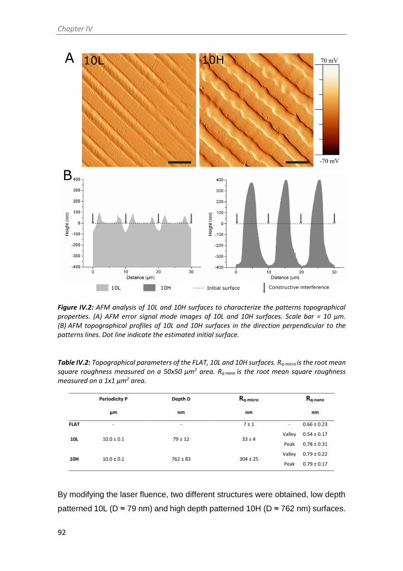
Chapter IV
92
Figure IV.2: AFM analysis of 10L and 10H surfaces to characterize the patterns topographical properties. (A) AFM error signal mode images of 10L and 10H surfaces. Scale bar = 10 μm. (B) AFM topographical profiles of 10L and 10H surfaces in the direction perpendicular to the patterns lines. Dot line indicate the estimated initial surface.
Table IV.2: Topographical parameters of the FLAT, 10L and 10H surfaces. Rq-micro is the root mean square roughness measured on a 50x50 µm2 area. Rq-nano is the root mean square roughness measured on a 1x1 µm2 area.
Periodicity P Depth D Rq-micro Rq-nano
µm nm nm nm
FLAT - - 7 ± 1 - 0.66 ± 0.23
10L 10.0 ± 0.1 79 ± 12 33 ± 4 Valley 0.54 ± 0.17
Peak 0.78 ± 0.31
10H 10.0 ± 0.1 762 ± 83 304 ± 25 Valley 0.79 ± 0.22
Peak 0.79 ± 0.17
By modifying the laser fluence, two different structures were obtained, low depth
patterned 10L (D ≈ 79 nm) and high depth patterned 10H (D ≈ 762 nm) surfaces.

Chapter IV
93
As expected, the topographical modifications increased the micro-roughness,
Rq-micro, of non-modified surfaces (FLAT) from 7.4 ± 1.3 nm up to 33.2 ± 3.7 nm
for 10L surfaces and 303.6 ± 24.9 nm for 10H series. However, nano-roughness
of FLAT samples and patterned surfaces, either at peaks or valleys, showed no
statistical differences. AFM error signal mode images (Figure IV.2A) for the two
different patterned surfaces confirmed that 10H surfaces presented homogenous
grooves with clearly identifiable peaks and valleys; in contrast, on 10L surfaces
the low depths hindered the identification of peaks compared to valleys. Figure
IV.2B presents the cross-section profiles of 10L and 10H surfaces directly
extracted from the AFM topographic images, which allowed characterizing the
shape of the peaks. Indeed, 10H is characterized by a sinusoidal shape with
valleys, where constructive interference occurs, and peaks, where destructive
interference takes place and thus, two melted material fronts joint. On the
contrary, 10L surfaces is composed of a low depth valley where the constructive
interferences met creating two small peaks at both sides and a non-modified flat
area where the beams interacted destructively. These two different
configurations, called respectively single and double-peak pattern surfaces, are
usual for metallic surfaces modified by DLIP, as described in Chapter III and in
previous studies 1,16. Such differences can be explained by the applied laser
fluencies: high fluencies, used for 10H series, provided enough energy to melt a
considerable amount of metal that flowed outside the constructive interference
spots towards the destructive interference spots, due to the surface tension
gradient resulting from the temperature gradient 16–18. At the destructive
interference spots the advancing melt fronts join, creating the characteristic
peaks. In the case of 10L series, the applied low fluence melted a lower quantity
of CoCr alloy and the two fronts could not joint together, generating two small
peaks surrounding the spots where the beams interfered constructively. In both
surfaces, 10L and 10H, the high temperatures applied during DLIP transformed
the crystalline oxide layer into a thicker amorphous oxide layer overall the
surface, as demonstrated in the Chapter III. Thus, considering the low roughness
of 10L surfaces, 10L series could be considered mainly as surfaces with chemical
changes, and a negligible topographical pattern.

Chapter IV
94
CoCr alloy ASTM F-90 is extensively used as stent material mainly due to its
capacity of forming a naturally passive oxide layer that confers very good
corrosion resistance properties to the material. As surface patterning by DLIP
could generate changes in the corrosion behaviour of the materials,
electrochemical assays and ion release tests were performed (Table IV.3). All
studied series presented statistically equal corrosion potentials of approximately
1000 mV, suggesting that DLIP did not modify the corrosion resistance of the
CoCr surfaces. Moreover, no corrosion pits were observed on the tested surfaces
(not shown), validating DLIP as a treatment that do not-modify the corrosion
resistance observed in FLAT surfaces. Ion release assays were performed in
Hank’s balanced salt solution at 37ºC during 7 days. The release of Ni ions,
susceptible to allergy, was not significantly higher on 10L and 10H surfaces,
compared to FLAT surface. The release of Co and Cr ions, on 10L surfaces was
slightly lower than on FLAT, indicating that 10L series are not toxic just as the
CoCr alloys used in the current stents. On the other hand, the release of ions
significantly increased on 10H series (Cr: 4.3 ± 0.3 ng; Co: 77.8 ± 8.6 ng)
compared to FLAT (Cr: 1.6 ± 0.3 ng; Co: 47.5 ± 16.0 ng). However, such higher
release should not be detrimental for the biological performance of these
materials. Firstly, the high toxicity and carcinogenic properties of Cr are
associated to its hexavalent form (chromium VI) 19, and we have shown in
Chapter III that DLIP generated only Cr (III) at the CoCr alloy oxide layer.
Secondly, it should be taken into consideration that stents are placed in the artery
and release metallic ions under blood flow conditions. Thus, if we consider 5 liters
as the normal blood quantity for an adult and the stent surface area being half of
the area of the studied samples, the release of Cr and Co from 10H surfaces
would be equivalent to 4.3x10⁻⁴ ng/ml and 7.8x10⁻³ ng/ml, respectively. These
values are 100,000 and 15,000 times lower, for Cr and Co, respectively, than the
maximum concentrations recommended by the World Health Organization
(Cr: 50 ng/ml; Co: 150 ng/ml) 20,21. Consequently, even if the released ions were
increased on 10H series compared to FLAT, the release of metallic ions after
DLIP patterning is kept at non-toxic levels.

Chapter IV
95
Table IV.3: Detailed results of corrosion resistance, ion release and zeta potential on CoCr surfaces before and after DLIP patterning. Corrosion potential and ion release were obtained according to the standard ISO 10993-15. Isoelectric point (IEP) and zeta potential (ζ) at pH 7.4 were measured.
Ion release Zeta potential
Corrosion potential Co ions Cr ions Ni ions IEP ζ at pH 7.4
mV ng ng ng pH mV
FLAT 1014.3 ± 10.1 47.5 ± 16.0 1.6 ± 0.3 12.4 ± 3.8 4.9 ± 0.0 - 34.5 ± 2.9
10L 1017.6 ± 9.5
23.3 ± 6.3 1.5 ± 0.2 9.4 ± 2.8
4.8 ± 0.0 - 39.7 ± 0.2
10H 1031.7 ± 6.1 77.8 ± 8.6 4.3 ± 0.3 17.5 ± 1.0 4.5 ± 0.0 - 11.5 ± 1.0
The zeta potential studies indicated that the IEP of the FLAT and the patterned
surfaces is around pH ~ 4.7. As the solution was more alkaline, the surfaces
showed a steadily more negative zeta potential. The ζ at pH 7.4 is very similar on
FLAT and 10L surfaces mainly because the roughness of 10L surfaces is
negligible. For 10H surfaces it was found a less negative surfaces charge
compared to FLAT due to the effect of the linear pattern. The effect of peaks and
valleys onto zeta potential measurements have been already described 22. The
fact that linear pattern retains charges inside the valleys prevents their detection
at the end of the channel and possibly generates an opposite flow, leading to a
decrease in measured zeta potential.
3.2. Biofunctionalization of CoCr and surface characterization
The studied peptides were synthesized with the structure and the characteristics
presented in Figure IV.1 and Table IV.1. As previously mentioned, both peptides
are composed of three distinct parts. First, the bioactive sequences, RGD and
YIGSR (in blue in Figure IV.1), which determine the biological functionality of the
biomolecule. The RGD sequence was chosen for its well-known effect on cell
adhesion 23–26 and YIGSR was selected for its ability to bind specifically to ECs
27–31. Secondly, the spacer units, three aminohexanoic acid (Ahx) (in red), which
ensure the appropriate accessibility of the functional sequences to interact with
cells. Indeed, in previous studies, it has been demonstrated that peptides with
spacer molecules shorter in length failed to influence the biological activity on the
coated surfaces 31,32. And finally, two lysines (in green) which contain primary
amines in their side chains as anchoring groups, to covalently attach the peptides
to the silanized surface.

Chapter IV
96
The effectiveness of silanization and functionalization of CoCr surfaces was
evaluated by ATR-FTIR (Figure IV.3), AFM (Figure IV.4) and XPS (Figure IV.5).
ATR-FTIR spectra of FLAT-CPTES, FLAT-RGD and FLAT-YIGSR surfaces are
presented in Figure IV.3.
Figure IV.3: ATR-FTIR of FLAT-CPTES, FLAT-RGD and FLAT-YIGSR surfaces from 700 to 1600 cm-1. Arrows indicate significant peaks.
On all the surfaces, the peak observed at 1267 cm-1, which corresponds to C = O
bonding, was the result of atmospheric contamination. On CPTES samples, Si-
O-R peaks, at 1100 cm-1, were related to the covalent bonding of the silane on
the surface 33,34. Also, the terminal chlorine group from the CPTES silanes was
detected at a wavelength of 870 cm-1. Finally, as CoCr alloys did not contain CH3
group, the CH3 peak, at 1430 cm-1, confirmed the presence of CPTES on FLAT-
CPTES surfaces. The spectra of RGD and YIGSR-coated surfaces displayed
exactly the same peaks detected on CPTES samples. In particular, no N bonding
peaks were detected, as it would be expected in the presence of peptides. This
observation could be due to the low sensitivity of the surface technique, which
would be not adequate to detect a low amount of biomolecule.

Chapter IV
97
AFM characterization was done to analyze the layer of silane and peptides
immobilized onto CoCr surfaces (Figure IV.4). As expected, FLAT surface
showed a smooth surface with some scratches from polishing, while CPTES
series presented small clusters of 6 nm height approximately (Figure IV.4A).
Similar differences were observed by T. Sargeant et al. 35 after silanization on
NiTi alloy surfaces. Moreover, FLAT-RGD, FLAT-YIGSR, 10L-CPTES and
10H-CPTES surfaces presented roughness values very similar to those
measured in the CPTES samples (Figure IV.4C). Indeed, all these five conditions
had Rq-nano values of about 2.5 nm with no statistical differences; whereas FLAT
samples presented values 4 times lower (Rq-nano = 0.66 ± 0.23 nm). The increment
of the Rq-nano roughness for silanized and functionalized surfaces, compared to
FLAT, can be thus attributed to the coating layer. Since no statistical differences
were found between silanized and functionalized surfaces, we can assume that
the peptide layer is very thin and not observable with AFM. Also, the similar
roughness observed on FLAT and patterned silanized surfaces suggested that
the efficiency of silanization is not affected by the DLIP process.
Figure IV.4B exhibits the phase map for the region of interest. It is found a single
phase for FLAT surfaces while CPTES series showed a bimodal phases
distribution at -33º and 8º. AFM phase imaging in tapping mode is directly related
to the viscoelastic properties of the analysed surface and, consequently, to the
surface hardness of the material. Thus, CPTES surfaces seemed to have
different materials properties, presumably related to the immobilization of silanes
onto CoCr surface. Also, the percentage of covered area by the coating was
calculated (Figure IV.4D). All functionalized surfaces presented an 85 % of
surface coverage and no statistical differences were observed between silanized
and functionalized surfaces onto both polished and patterned CoCr surfaces.
The increased roughness and the presence of two different phases on
FLAT-CPTES compared to FLAT confirmed the attachment of CPTES silane on
the surface. Since the same results were observed on 10L-CPTES and
10H-CPTES, we can conclude that the silanization process occurred with the
same efficiency on FLAT and patterned surfaces. However, as FLAT-RGD and
FLAT-YIGSR presented similar roughness and surface coverage than CPTES
surfaces, we could not ascertain whether the peptides were present or not.

Chapter IV
98
Figure IV.4: AFM analysis of FLAT, FLAT-CPTES, FLAT-RGD, FLAT-YIGSR, 10L-CPTES and 10H-CPTES surfaces to characterize the silane and peptides layers. Scale bar = 500 nm. Columns marked with different letters belong to statistically different groups (p-value < 0.05). (A) AFM error signal mode images and topographical profiles of FLAT and CPTES surfaces. (B) Tapping-mode AFM phase images and phases distributions of FLAT and CPTES surfaces. (C) Roughness Rq-nano calculated from AFM height images. (D) % of area covered by the coating calculated from AFM phase images.
To evaluate the presence of immobilized peptides onto functionalized surfaces,
FLAT, FLAT-RGD and FLAT-YIGSR surfaces were characterized by XPS
(Figure IV.5). Untreated CoCr alloys displayed characteristic peaks of C 1s, O
1s, Co 2p and Cr 2p. The presence of carbon is attributed to atmospheric organic
contaminants 36. A small amount of nitrogen (N 1s) and silicon (Si 2p)
contaminations was also detected. On FLAT-RGD and FLAT-YIGSR surfaces
the percentage of Si 2p was increased due to the presence of CPTES. A
significant increase in N 1s was also detected for functionalized surfaces

Chapter IV
99
compared to FLAT (FLAT: 0.66 ± 0.05 %; FLAT-RGD: 1.56 ± 0.28 %;
FLAT-YIGSR: 1.53 ± 0.03 %). This presence of nitrogen was attributed to the
amide groups and other amino functionalities characteristic of the peptide
sequences 37, thereby confirming the attachment of the RGD and YIGSR
peptides onto the surfaces. However, the fact that Cl 2p was detected as well
after the functionalization indicates that not all the electrophilic points of CPTES
(i.e. –CH2-Cl) reacted with the peptides. This observation suggests a limited
coverage of the silane layer by the peptides, in agreement with the low % of N 1s
quantified and FTIR data. Finally, it is worth to mention that no statistical
differences were observed in N 1s, Si 2p and Cl 2p signals between FLAT-RGD
and FLAT-YIGSR surfaces, suggesting that the functionalization occurred with
the same effectiveness and the amount of immobilized peptides was very similar.
Figure IV.5: Analysis of the chemical composition (atomic %) of FLAT, FLAT-RGD and FLAT-YIGSR surfaces by XPS. For Si 2p, N 1s and Cl 2p, bars designated with different letters belong to statistically different groups (p-value < 0.05).
To evaluate the stability of the covalent immobilization of the different peptides
FLAT-RGD and FLAT-YIGSR surfaces were subjected to either gamma radiation

Chapter IV
100
sterilization or ultrasound sonication with MilliQ water (Figure IV.6). The amount
of immobilized fluorescent peptide onto FLAT-RGD and FLAT-YIGSR was
calculated before the stability treatments and was statistically the same,
confirming the results observed with XPS. The amount of immobilized peptide
slightly decreased for both peptides after the stability tests, although the
percentages of peptide loss were very moderate and overall, 74% or more of the
peptides remained on the surface (FLAT-RGD-RG: 95.2%;
FLAT-RGD-US: 81.5%; FLAT-YIGSR-RG: 74.2% and
FLAT-YIGSR-US: 75.7%). Ultrasonication represents an aggressive mechanical
challenge and may remove physisorbed peptides attached through weak
bonds 38.Gamma radiation could affect chemical covalent or weak bonding and,
consequently, remove a piece or the entire peptide 39. It should be noted that the
CF fluorescent molecule was coupled at the N-terminus of the peptide sequence,
i.e. at the opposite of the anchoring regions of the C-terminus, thus, the detection
of fluorescence after the RG sterilization indicates that more than 74 % of
attached peptides remained entire. These results suggest that the majority of the
peptide coatings are stable to RG sterilization and mechanical stress, which both
occur during stent implantation.
Figure IV.6: Quantification by indirect fluorescence of the amount of immobilized peptides onto FLAT and biofunctionalized surfaces before (FLAT-RGD and FLAT-YIGSR) and after sterilization with gamma radiation (FLAT-RGD-RG and FLAT-YIGSR-RG) or after ultrasound sonication (FLAT-RGD-US and FLAT-YIGSR-US). Bars designated with different letters belong to statistically different groups (p-value < 0.05).

Chapter IV
101
3.1. HUVECs adhesion and alignment
The number of adhered HUVECs onto modified CoCr surfaces was evaluated by
fluorescent microscopy (Figure IV.7A). Polished and patterned non-
functionalized surfaces presented the same number of adherent cells, proving
that the nanotopography, alone, did not influence HUVECs adhesion onto CoCr
surfaces. Previous studies have reported higher cell adhesion on linear patterned
surfaces with the same periodicity (i.e. around 10 µm) 3,8,40–42. However, the
investigations on DLIP patterned surfaces described no changes in cell adhesion
1,43, possibly as a result of the relatively low pattern depth (< 1 µm) introduced by
this technique and the non-sharp shape of the patterns peaks. Differences in cell
area were neither observed between FLAT and 10L surfaces. In contrast, this
parameter was statistically reduced on 10H. The reason for such behavior
probably relied on the effect of the peaks geometry that acted as a barrier for
cellular spreading. Thus, we considered that high depth DLIP patterning had no
effect on cell number but reduced slightly the spreading of attached HUVECs.
On the contrary, surface functionalization with the peptides did not modify the cell
mean area but significantly increased the number of attached HUVECs, with
YIGSR functionalization yielding the highest values of cell adhesion. Indeed, onto
RGD and YIGSR functionalized surfaces cell numbers increased approximately
80% and 120%, respectively, compared to the non-functionalized surfaces. The
observed increased amount of adhered cells for YIGSR, combined with the fact
that this peptide sequence specifically targets ECs 27,29,44, indicates that CoCr
functionalization with YIGSR peptides is a feasible way to promote ECs adhesion
while avoiding the adhesion of SMCs or platelets 31.
Next, HUVECs alignment was characterized by fluorescent staining of actin fibers
(Figure IV.7A) and FE-SEM visualization (Figure IV.7B). A cell was considered
aligned if the angle between the patterned lines and the longest segment of the
cell was inferior to 30º. Consequently, a surface having no effect on the ECs
orientation should present around 33% of aligned cells. HUVECs alignment was
directly related to the pattern dimension. FLAT series and 10L-patterned series,
functionalized or not, produced a percentage of HUVECs alignment between 31
and 40 %, and thus had little impact on cellular alignment. The designed
patterning of 10H surfaces, however, induced a remarkable alignment of
HUVECs, of 79 ± 7 %, 81 ± 12 % and 75 ± 12 % for 10H, 10H-RGD and

Chapter IV
102
Figure IV.7: HUVECs adhesion and spreading on FLAT, patterned or/and functionalized CoCr surfaces after 12 h of incubation. (A) Cell number, cells mean area and % of aligned cells were obtained by fluorescent microscopy. Images were analysed with FIJI software. Bars designated with different letters belong to statistically different groups (p-value < 0.05). (B) FE-SEM images of HUVECs on FLAT, 10H, FLAT-YIGSR and 10H-YIGSR surfaces. Scale bar = 30 μm.

Chapter IV
103
10H-YIGSR, respectively, without statistical differences within tem. Thus,
10H series induced the alignment of HUVECs following the direction of the
patterns and reduced HUVECs mean area due to the micro-level of the pattern.
Patterns of 10L surfaces had grooves with a depth 10 times smaller than ECs
thickness 45 and it is probable that they simply act as a pavement instead of a
wall where the HUVECs can easily spread in all directions.
3.2. HUVECs migration
Cell migration was evaluated through the injury coverage ratio, which was defined
as the percentage of injury area covered by HUVEC’s after 24 h (Figure IV.8).
Figure IV.8: HUVECs migration on FLAT, patterned and/or functionalized CoCr surfaces at 0 h and 24 h timepoints. The percentage indicates the percentage of the respective initial injury area covered by HUVECs at 24 h. Initial gap width = 500 ± 50 µm. Scale bar = 400 µm.
The migration of HUVECs was observed on all CoCr surfaces. On non-
functionalized FLAT and 10L surfaces series injury recovery was of only 18 %

Chapter IV
104
and 21 %, respectively, demonstrating that 10L patterns did not have an effect
on HUVECs migration. On the contrary, 10H nanopatterns presented a higher
value of 78% of recovery, indicating an accelerated migration, probably due the
alignment produced by the patterned topography 3,40,46,47. When FLAT and 10L
CoCr surfaces were functionalized with RGD and YIGSR peptides, HUVECs
migration was significantly accelerated (more than 2-fold), with no differences
detected between the two peptides. Noteworthy, the combination of 10H
nanopatterns and functionalization with RGD and YIGSR peptides significantly
improved HUVECs migration compared to all surfaces: 10H-RGD and
10H-YIGSR surfaces presented an almost complete healing of 97 % and 98 %,
respectively. This result proves that combining DLIP patterning and
functionalization with RGD or YIGSR peptides, which increase HUVECs
alignment and adhesion, respectively, synergistically accelerates HUVECs
migration after 24 h.
3.3. HUVECs proliferation
The effect of DLIP and RGD and YIGSR functionalization on HUVECs
proliferation was assessed by an Alamar blue assay after 2, 5 and 8 days of cell
culture (Figure IV.9). As expected, HUVECs proliferation increased on all
surfaces over time. After 2 days, cell number was significantly higher on all
peptide-functionalized surfaces compared to non-functionalized FLAT, 10L and
10H surfaces. After 5 and 8 days, this effect was emphasized. Also linear
patterning had an effect and, at 5 and 8 days, a higher cell proliferation was
observed on 10H series compared to the respective FLAT and 10L surfaces. This
was probably induced by the faster cell migration observed on these
nanopatterns. Indeed, when proliferating, cells have less space and are in close
contact with other cells. Consequently, due the effect of contact inhibition of
proliferation 48,49, proliferation slow down. On a surface generating a faster
migration, like 10H surfaces, cells tend to separate from the others faster and
consequently proliferation is accelerated compared to surfaces with a slower
migration rate like FLAT and 10L surfaces. Finally, after 8 days, surfaces
functionalized with YIGSR showed a higher cell number compared to the

Chapter IV
105
respective surfaces functionalized with RGD, corroborating the higher potential
of YIGSR to direct HUVEC behavior.
Figure IV.9: HUVECs proliferation on FLAT, patterned and/or functionalized CoCr surfaces at 2, 5 and 8 days of cell culture obtained by Alamar blue assay. Bars designated with different letters belong to statistically different groups (p-value < 0.05).
Overall, cell studies determined that peptide functionalization increased ECs
adhesion and 10H DLIP patterning induced HUVECs alignment. Noteworthy, the
synergy of these two effects on 10H-RGD and 10H-YIGSR surfaces accelerated
HUVECs migration and proliferation. Blood circulating in the artery contains a low
quantity of ECs. Consequently, the adhesion of ECs on the stent, which would
be required to accelerate arterial regeneration, is limited, and, therefore, ECs
migration from the surrounding healthy tissue plays a crucial role in the
endothelialization process 50,51. In addition, previous studies demonstrated that
DLIP patterned CoCr surfaces are anti-thrombogenic 1 and that CoCr alloy
functionalized with YIGSR do not promote high levels of SMC adhesion 31.
Therefore, CoCr alloys patterned by DLIP and functionalized with YIGSR seem

Chapter IV
106
to have a great potential to accelerate endothelium healing without generating
platelet aggregation and SMC proliferation.
4. Conclusions
In this work, we explored the possibility to increase specifically ECs adhesion,
migration and proliferation on CoCr surfaces by combining topographical
modification and biofunctionalization techniques.
Flat CoCr surfaces were successfully modified by DLIP technique obtaining linear
nanopatterned surfaces. These nanotopographies did not modify the corrosion
properties and the surface charge of the CoCr alloy.
To evaluate the combined effect of topographical modifications with
biofunctionalization, RGD and YIGSR cell adhesive peptides were covalently
immobilized to the surfaces through CPTES silanization. The coatings were
characterized by physico-chemical methods and, moreover, showed stability
against gamma radiation sterilization and ultrasonication.
Cell studies indicated that RGD and YIGSR-coated surfaces induce a significant
increase in ECs adhesion compared to non-functionalized surfaces. Moreover,
10H pattern surfaces aligned the 80 % of adhered ECs while 10L did not affect
cell alignment. When 10H patterned surfaces were functionalized, an accelerated
ECs migration and proliferation was observed. Consequently, a positive synergy
between surface linear patterning and functionalization was described.
Therefore, DLIP patterned surfaces functionalized with RGD or YIGSR hold great
potential to overcome clinical limitations of current stents by enhancing surface
endothelialization.

Chapter IV
107
References
(1) Schieber, R.; Lassarre, F.; Hans, M.; Fernandez-Yague, M.; Diaz-Ricart, M.; Escolar,
G.; Ginebra, M.-P.; Mucklich, F.; Pegueroles, M. Direct Laser Interference
Patterning of CoCr Alloy Surfaces to Control Endothelial Cell and Platelet
Response for Cardiovascular Applications. Accept. Adv. Healthc. Mater. 2016.
(2) Zorlutuna, P.; Rong, Z.; Vadgama, P.; Hasirci, V. Influence of Nanopatterns on
Endothelial Cell Adhesion: Enhanced Cell Retention under Shear Stress. Acta
Biomater. 2009, 5 (7), 2451–2459.
(3) Biela, S. a; Su, Y.; Spatz, J. P.; Kemkemer, R. Different Sensitivity of Human
Endothelial Cells, Smooth Muscle Cells and Fibroblasts to Topography in the
Nano-Micro Range. Acta Biomater. 2009, 5 (7), 2460–2466.
(4) Liliensiek, S. J.; Wood, J. a; Yong, J.; Auerbach, R.; Nealey, P. F.; Murphy, C. J.
Modulation of Human Vascular Endothelial Cell Behaviors by Nanotopographic
Cues. Biomaterials 2010, 31 (20), 5418–5426.
(5) Morgan, J. T.; Wood, J. a; Shah, N. M.; Hughbanks, M. L.; Russell, P.; Barakat, A. I.;
Murphy, C. J. Integration of Basal Topographic Cues and Apical Shear Stress in
Vascular Endothelial Cells. Biomaterials 2012, 33 (16), 4126–4135.
(6) Falconnet, D.; Csucs, G.; Michelle Grandin, H.; Textor, M. Surface Engineering
Approaches to Micropattern Surfaces for Cell-Based Assays. Biomaterials 2006,
27 (16), 3044–3063.
(7) Guillem-Marti, J.; Delgado, L.; Godoy-Gallardo, M.; Pegueroles, M.; Herrero, M.;
Gil, F. J. Fibroblast Adhesion and Activation onto Micro-Machined Titanium
Surfaces. Clin. Oral Implants Res. 2013, 24 (7), 770–780.
(8) Lu, J.; Rao, M. P.; MacDonald, N. C.; Khang, D.; Webster, T. J. Improved Endothelial
Cell Adhesion and Proliferation on Patterned Titanium Surfaces with Rationally
Designed, Micrometer to Nanometer Features. Acta Biomater. 2008, 4 (1), 192–
201.
(9) Li, Y.; Thouas, G. a; Chen, Q.-Z. Biodegradable Soft Elastomers:
Synthesis/properties of Materials and Fabrication of Scaffolds. RSC Adv. 2012, 2
(22), 8229–8242.

Chapter IV
108
(10) Mucklich, F.; Lasagni, A.; Daniel, C. Laser Interference Metallurgy – Using
Interference as a Tool for Micro/nano Structuring. Int. J. Mater. Res 2006, 97,
1337–1344.
(11) Mas-Moruno, C.; Fraioli, R.; Albericio, F.; Manero, J. M.; Gil, F. J. Novel Peptide-
Based Platform for the Dual Presentation of Biologically Active Peptide Motifs on
Biomaterials. ACS Appl. Mater. Interfaces 2014, 6, 6525–6536.
(12) Horcas, I.; Fernández, R.; Gómez-Rodríguez, J. M.; Colchero, J.; Gómez-Herrero,
J.; Baro, A. M. WSXM: A Software for Scanning Probe Microscopy and a Tool for
Nanotechnology. Rev. Sci. Instrum. 2007, 78 (1).
(13) International Organization for Standardization. Biological Evaluation of Medical
Devices - Part 15: Identification and Quantification of Degradation Products from
Metals and Alloys, 2000.
(14) Tzoneva, R.; Heuchel, M.; Groth, T.; Altankov, G.; Albrecht, W.; Paul, D. Fibrinogen
Adsorption and Platelet Interactions on Polymer Membranes. J. Biomater. Sci.
Polym. Ed. 2002, 13 (9), 1033–1050.
(15) Schindelin, J.; Arganda-Carreras, I.; Frise, E.; Kaynig, V.; Longair, M.; Pietzsch, T.;
Preibisch, S.; Rueden, C.; Saalfeld, S.; Schmid, B.; Tinevez, J.-Y. J.-Y.; White, D. J.;
Hartenstein, V.; Eliceiri, K.; Tomancak, P.; Cardona, A.; Liceiri, K.; Tomancak, P.;
A., C. Fiji: An Open Source Platform for Biological Image Analysis. Nat. Methods
2012, 9 (7), 676–682.
(16) Lasagni, a.; Mücklich, F. FEM Simulation of Periodical Local Heating Caused by
Laser Interference Metallurgy. J. Mater. Process. Technol. 2009, 209 (1), 202–209.
(17) von Allmen, M.; Blatter, A. Laser-Beam Interactions with Materials. Physical
Principles and Applications, Springer S.; 1995.
(18) Hans, M.; Müller, F.; Grandthyll, S.; Hüfner, S.; Mücklich, F. Applied Surface
Science Anisotropic Wetting of Copper Alloys Induced by One-Step Laser Micro-
Patterning. 2012, 263, 416–422.
(19) Dayan, A. D.; Paine, A. J. Mechanisms of Chromium Toxicity, Carcinogenicity and
Allergenicity: Review of the Literature from 1985 to 2000. Hum. Exp. Toxicol.
2001, 20 (9), 439–451.
(20) Chen, Q.; Thouas, G. A. Metallic Implant Biomaterials. Mater. Sci. Eng. R Reports
2015, 87, 1–57.

Chapter IV
109
(21) Madl, A. K.; Kovochich, M.; Liong, M.; Finley, B. L.; Paustenbach, D. J.;
Oberdörster, G. Toxicology of Wear Particles of Cobalt-Chromium Alloy Metal-on-
Metal Hip Implants Part II: Importance of Physicochemical Properties and Dose in
Animal and in Vitro Studies as a Basis for Risk Assessment. Nanomedicine
Nanotechnology, Biol. Med. 2015, 11 (5), 1285–1298.
(22) Schnitzer, C.; Ripperger, S. Influence of Surface Roughness on Streaming Potential
Method. Chem. Eng. Technol. 2008, 31 (11), 1696–1700.
(23) Hersel, U.; Dahmen, C.; Kessler, H. RGD Modified Polymers: Biomaterials for
Stimulated Cell Adhesion and beyond. Biomaterials 2003, 24 (24), 4385–4415.
(24) Pierschbacher, M. D.; Ruoslahti, E. Cell Attachment Activity of Fibronectin Can Be
Duplicated by Small Synthetic Fragments of the Molecule. Nature 1984, 309
(5963), 30–33.
(25) Zheng, W.; Wang, Z.; Song, L.; Zhao, Q.; Zhang, J.; Li, D.; Wang, S.; Han, J.; Zheng,
X.-L.; Yang, Z.; Kong, D. Endothelialization and Patency of RGD-Functionalized
Vascular Grafts in a Rabbit Carotid Artery Model. Biomaterials 2012, 33 (10),
2880–2891.
(26) Hoesli, C. a; Garnier, A.; Juneau, P.-M.; Chevallier, P.; Duchesne, C.; Laroche, G. A
Fluorophore-Tagged RGD Peptide to Control Endothelial Cell Adhesion to
Micropatterned Surfaces. Biomaterials 2014, 35 (3), 879–890.
(27) Hubbell, J. A.; Massia, S.; Desai, N.; Drumheller, P. Endothelial Cell-Selective
Materials for Tissue Engineering in the Vascular Graft via a New Receptor. Narure
Biotechnol. 1991, 9, 568–572.
(28) Jun, H.-W.; West, J. Development of a YIGSR-Peptide-Modified Polyurethaneurea
to Enhance Endothelialization. J. Biomater. Sci. Polym. Ed. 2004, 15 (1), 73–94.
(29) Jun, H.-W.; West, J. L. Endothelialization of Microporous YIGSR/PEG-Modified
Polyurethaneurea. Tissue Eng. 2005, 11 (7–8), 1133–1140.
(30) Jun, H.-W.; West, J. L. Modification of Polyurethaneurea with PEG and YIGSR
Peptide to Enhance Endothelialization without Platelet Adhesion. J. Biomed.
Mater. Res. B. Appl. Biomater. 2005, 72 (1), 131–139.
(31) Castellanos, M. I.; Mas-Moruno, C.; Grau, A.; Serra-Picamal, X.; Trepat, X.;
Albericio, F.; Joner, M.; Manero, J. M.; Pegueroles, M. Functionalization of CoCr
Surfaces with Cell Adhesive Peptides to Promote HUVECs Adhesion and

Chapter IV
110
Proliferation. Appl. Surf. Sci. 2016, 393, 82–92.
(32) Mas-Moruno, C.; Dorfner, P. M.; Manzenrieder, F.; Neubauer, S.; Reuning, U.;
Burgkart, R.; Kessler, H. Behavior of Primary Human Osteoblasts on Trimmed and
Sandblasted Ti6Al4V Surfaces Functionalized with Integrin αvβ3-Selective Cyclic
RGD Peptides. J. Biomed. Mater. Res. A 2013, 101 (1), 87–97.
(33) Tan, G.; Zhang, L.; Ning, C.; Liu, X.; Liao, J. Preparation and Characterization of
APTES Films on Modification Titanium by SAMs. Thin Solid Films 2011, 519 (15),
4997–5001.
(34) Kim, J.; Seidler, P.; Wan, L. S.; Fill, C. Formation, Structure, and Reactivity of
Amino-Terminated Organic Films on Silicon Substrates. J. Colloid Interface Sci.
2009, 329 (1), 114–119.
(35) Sargeant, T. D.; Rao, M. S.; Koh, C.-Y.; Stupp, S. I. Covalent Functionalization of
NiTi Surfaces with Bioactive Peptide Amphiphile Nanofibers. Biomaterials 2008,
29 (8), 1085–1098.
(36) Healy, K. E.; Ducheyne, P. Oxidation Kinetics of Titanium Thin Films in Model
Physiologic Environments. J. Colloid Interface Sci. 1992, 150 (2), 404–417.
(37) Rezania, A.; Johnson, R.; Lefkow, A. R.; Healy, K. E. Bioactivation of Metal Oxide
Surfaces. 1. Surface Characterization and Cell Response. Langmuir 1999, 15 (20),
6931–6939.
(38) Godoy-Gallardo, M.; Mas-Moruno, C.; Yu, K.; Manero, J. M.; Gil, F. J.;
Kizhakkedathu, J. N.; Rodriguez, D. Antibacterial Properties of hLf1-11 Peptide
onto Titanium Surfaces: A Comparison Study between Silanization and Surface
Initiated Polymerization. Biomacromolecules 2015, 16 (2), 483–496.
(39) Yang, Y.; Porte, M. C.; Marmey, P.; El Haj, A. J.; Amedee, J.; Baquey, C. Covalent
Bonding of Collagen on poly(L-Lactic Acid) by Gamma Irradiation. Nucl.
Instruments Methods Phys. Res. Sect. B Beam Interact. with Mater. Atoms 2003,
207 (2), 165–174.
(40) Song, K. H.; Kwon, K. W.; Song, S.; Suh, K.-Y.; Doh, J. Dynamics of T Cells on
Endothelial Layers Aligned by Nanostructured Surfaces. Biomaterials 2012, 33 (7),
2007–2015.
(41) Palmaz, J. C.; Benson, A.; Sprague, E. A. Influence of Surface Topography on
Endothelialization of Intravascular Metallic Material. J. Vasc. Interv. Radiol. 1999,

Chapter IV
111
10 (4), 439–444.
(42) Ranjan, A.; Webster, T. J. Increased Endothelial Cell Adhesion and Elongation on
Micron-Patterned Nano-Rough Poly(dimethylsiloxane) Films. Nanotechnology
2009, 20 (30), 305102–305112.
(43) Fayou Yu, Frank Mucklich, Ping Li, Hao Shen, S. M.; Claus-Michael Lehr, and U. B.
In Vitro Cell Response to a Polymer Surface Micropatterned by Laser Interference
Lithography. Biomacromolecules 2005, 6, 1160–1167.
(44) Massia, S. P.; Hubbell, J. A. Convalent Surface Immobilization of Arg-Gly-Asp- and
Tyr-Ile-Gly-Ser-Arg-Containing Peptides to Obtain Well-Defined Cell-Adhesive
Substrates. Anal. Biochem. 1990, 187 (2), 292–301.
(45) Alberts, B.; Johnson, A.; Lewis, J. Molecular Biology of the Cell, 4th editio.; Science,
N. Y. G., Ed.; 2002.
(46) Teichmann, J.; Morgenstern, A.; Seebach, J.; Schnittler, H.-J.; Werner, C.; Pompe,
T. The Control of Endothelial Cell Adhesion and Migration by Shear Stress and
Matrix-Substrate Anchorage. Biomaterials 2012, 33 (7), 1959–1969.
(47) Bouta, E. M.; McCarthy, C. W.; Keim, A.; Wang, H. B.; Gilbert, R. J.; Goldman, J.
Biomaterial Guides for Lymphatic Endothelial Cell Alignment and Migration. Acta
Biomater. 2011, 7 (3), 1104–1113.
(48) McClatchey, A. I.; Yap, A. S. Contact Inhibition (of Proliferation) Redux. Curr. Opin.
Cell Biol. 2012, 24 (5), 685–694.
(49) Cho, E. H.; Dai, Y. SIRT1 Controls Cell Proliferation by Regulating Contact
Inhibition. Biochem. Biophys. Res. Commun. 2016, 478 (2), 868–872.
(50) Wei, Y.; Ji, Y.; Xiao, L. L.; Lin, Q. kui; Xu, J. ping; Ren, K. feng; Ji, J. Surface
Engineering of Cardiovascular Stent with Endothelial Cell Selectivity for in Vivo
Re-Endothelialisation. Biomaterials 2013, 34 (11), 2588–2599.
(51) Kouvroukoglou, S.; Dee, K. C.; Bizios, R.; McIntire, L. V; Zygourakis, K. Endothelial
Cell Migration on Surfaces Modified with Immobilized Adhesive Peptides.
Biomaterials 2000, 21 (17), 1725–1733.

Chapter V
112
Table of Contents
Chapter V: Solvent-cast poly(L-lactic acid) surfaces functionalized by sodium hydroxide
etching, oxygen plasma or cutinase enzyme hydrolysis for 3D-printed bioresorbable
stent fabrication ........................................................................................................... 113
1. Introduction ...................................................................................................... 114
2. Materials and methods .................................................................................... 115
2.1. Materials ................................................................................................... 115
2.2. PLLA films by solvent casting .................................................................... 115
2.3. PLLA films surface activation .................................................................... 116
2.4. PLLA films characterization ...................................................................... 116
2.5. Surface characterization ........................................................................... 118
2.6. PLLA films degradation ............................................................................. 119
2.7. HUVECs adhesion ..................................................................................... 119
2.8. 3D-printed BRS obtained by solvent-cast direct write technique ............ 120
2.9. Statistical analysis ..................................................................................... 120
3. Results and discussion ...................................................................................... 120
3.1. PLLA film properties ................................................................................. 121
3.2. Surface characterization ........................................................................... 123
3.3. Degradation of PLLA films ........................................................................ 126
3.4. HUVECs adhesion ..................................................................................... 129
3.5. BRS obtained by solvent-cast direct write technique .............................. 131
3. Conclusions ....................................................................................................... 131
References .................................................................................................................... 133

Chapter V
113
Chapter V: Solvent-cast poly(L-lactic acid) surfaces functionalized by sodium hydroxide etching, oxygen plasma or cutinase enzyme hydrolysis for 3D-printed bioresorbable stent fabrication

Chapter V
114
1. Introduction
Surface modifications onto biomaterials are a common approach to control
biological response and could be classified in three main categories. First,
topographical modifications that obtain specific nano- or micro- patterned
surfaces can accelerate ECs migration 1,2. Second, physico-chemical
modifications that generate suitable functional groups 3,4 and/or modulate surface
energy 5,6 have demonstrated to modify ECs adhesion and spreading. Third,
surface biofunctionalization by immobilizing specific biomolecules derived from
extracellular matrix (ECM) proteins that have selectivity for ECs, could facilitate
a cascade of biological events and eventually regenerate the damaged area with
a functional endothelium 7–9. A strong covalent bonding between the implant and
the biomolecules is desired to obtain a stable biofunctionalization 10. The most
common chemical routes to obtain covalent bonding are the generation of
functional groups at the surface, generally carboxyl (– COOH) or hydroxyl (– OH)
groups, which react with a specific part of the biomolecule. Consequently,
modifications that increase surface implant functional groups are of double
interest since they could increase biocompatibility and enhance
biofunctionalization. In that sense, surface treatments such as cold plasma
treatment 11–13, ultraviolet irradiation 3, sodium hydroxide (NaOH) etching 14,15 or
ozone irradiation 4 have shown to ameliorate surface functionalization. Also,
enzymatic treatments have been proposed and successfully used for the surface
modification of natural and synthetic polymers 9,16. For polyesters, such as PLLA,
the hydrolysis of the ester bond by applying cutinase enzymes generate new
hydroxyl and carboxyl groups onto the surface 9,17.
Also, common stent fabrication processes do not allow to personalized stent
shape. Consequently, in complex arteries stent implantation is impossible.
3D-printing could be a strategy to produce each stent with a shape fully
complementary to the target damaged artery. In particular, solvent-cast direct
write technique have shown promising results to obtain complex 3D-printed
shapes with PLLA inks 18.
The aim of this work was to elaborate and characterize solvent-casted PLLA
functionalized surfaces to enhance ECs adhesion and to assess the use of this

Chapter V
115
process and biomaterial to fabricate 3D-printed BRS. To assess biocompatibility,
mechanical and degradation properties of the modified PLLA by solvent-casting
it was evaluated cytotoxicity, crystallinity, molecular weight, Young modulus,
ultimate tensile strength (UTS) and degradation rates. The effect of the different
functionalization processes on PLLA properties was compared by characterizing
surface roughness, surface wettability, films degradation, surface chemical
properties and ECs adhesion. Finally, 3D-printed PLLA bioresorbable stent were
obtained by the solvent-cast direct write technique to assess its feasibility.
2. Materials and methods
2.1. Materials
Medical grade poly-L-lactic acid (PLLA) pellets (PURASORB PL65,
Mw ≈ 1650000 g/mol) were obtained from Purac Biomaterials (Gorinchem,
Netherlands). PLLA pellets were stored in a desiccator at room temperature (RT).
Commercial PLLA films of 50 µm thick with a 37 % crystallinity (ME331050,
Goodfellow, Coraopolis, USA) were used as reference. Samples made of this
commercial films were coded as COM.
Biodegradable PLLA peripheral stent REMEDY (Kyoto Medical Planning, Japan)
was used in this study as positive control. Sample made of this commercial stent
were coded as STNT.
Humicola insolens cutinase enzyme (HiC) was kindly provided by Novozymes
(Beijing, China) and used as received without any purification steps.
Cellular experiments were conducted using HUVECs in the exact same
conditions as in Chapter III (section 2.1.).
2.2. PLLA films by solvent casting
The PLLA films were manufactured by solvent-casting method 19. Previously,
PLLA pellets were dried in an oven with controlled argon atmosphere at 80ºC for
2 h. Then, PLLA pellets were dissolved in chloroform (Sigma-Aldrich, Germany)
at a 3.6% weight versus volume (w/v) ratio. The dissolution took approximately
48 h on an orbital shaker at RT. Once the PLLA was completely dissolved, the
obtained paste was spread on a 150 mm diameter glass petri dish and

Chapter V
116
maintained 48 h under a chloroform saturated atmosphere to decrease the
solvent evaporation rate. The studied surface was the one in contact with the
glass petri dish. The obtained films had a thickness of approximately ≈ 150 µm.
The obtained films were coded as SC. To increase crystallinity, the films were
thermally treated at 80ºC during 12 h and coded as TT. Finally, to characterize
the films, they were cut into 10 mm diameter discs.
2.3. PLLA films surface activation
Three different techniques of surface activation were applied to the fabricated TT
films:
Cold plasma: Low pressure oxygen plasma in a 13.56 MHz radiofrequency
reactor Diener Femto (Diener, Germany) was applied to TT films. At the center
of the reactor an oxygen plasma was generated at 0.4 mbar pressure and
100 W discharge power during 2 min. Details on the experimental setting can
be found in a previous study 20. Obtained samples were coded as PL.
Chemical etching: TT films were chemically activated by submerging the
samples in a 1 M sodium hydroxide (NaOH) solution under sonication during
1 h at RT. After, treated samples were cleaned twice in distilled water during
30 min to remove NaOH residues and samples were coded as NA.
Enzyme treatment: Previously to cutinase enzymes activation, TT films were
prewashed as described in a previous study 21. Briefly, samples were
submerged successively in L-1 Triton X100, Na2CO3 solution and double
distilled water (ddH2O) for 30 min at 37°C and 130 rpm. After, cutinase
enzymes were diluted in 100 mM Tris-HCl buffer with a pH=7 to obtain a
10 µM enzyme solution. The films were immersed in 1 ml of the enzyme
solution at 37ºC on an orbital shaker at 100 rpm during 24 h. Finally, films
were cleaned with the previous protocol and obtained samples were coded
as ENZ.
2.4. PLLA films characterization
Gel permeation chromatography (GPC) analyses were performed in an Agilent
HPLC chromatograph 1260 Infinity series (Agilent Technologies, USA).
Separation was carried in a Waters Styragel HR 5E column (USA) using CHCl3
(HPLC grade) as eluent. Samples with concentration between 0.2 to 0.4 mg/ml

Chapter V
117
were analyzed. The used flow was of 0.4 ml/min and the amount of injected
samples was 20 µl. Molecular weights were calculated after calibration with
PMMA standards from Sigma-Aldrich (Germany), molecular weight calibration
range was between 2.7 million to 2 thousands Dalton. Calculations were
performed with the Chemstation Software (Agilent Technologies).
Thermal analysis of the different PLLA samples were obtained by differential
scanning calorimetry (DSC) with the instrument DSC 2920 Modulated (TA
Instruments, USA) and following the ASTM D3418-03 standard 22. An empty
aluminum pan was used as reference. 10 ng samples were run in a nitrogen
atmosphere at 10ºC.min-1 heating ramp from 20 to 220ºC. The enthalpy of
fusion (ΔHm) and the enthalpy of crystallization (ΔHcc) were obtained from the
scan and used to calculate the percentage of crystallinity through the equation
Xc = (ΔHm – ΔHcc) / ΔH0m where ΔH0m = 93 J/g is the enthalpy of fusion of a
100% crystalline PLLA 23,24.
Mechanical properties of PLLA films were determined by tensile test (DY 34,
Adamel Lhomargy, France) according to the standard ASTM D882 – 02 25 using
a 100 N load cell. First, PLLA films were cut following the standard ASTM D6287
– 98 26 to obtain for each studied condition 5 samples of 150 mm length and 10
mm width. The rate of grip separation was set to 15 mm/min and the curve load
versus extension was recorded at RT. From the curve, Young modulus (E) and
ultimate tensile strength (UTS) were obtained.
To detect residues of chloroform in the PLLA films energy-dispersive X-ray
spectroscopy (EDX) was performed with a Zeiss Neon40 FE-SEM microscope
(Carl Zeiss NTS GmbH, Germany). Five measurements at 7 kV were done for
each condition.
The in vitro cytotoxicity of the PLLA films was evaluated by extracts using lactate
dehydrogenase (LDH) enzyme measurement on HUVECs. The extracts were
prepared according to ISO 10993-5 27 submerging the different fabricated PLLA
films in complete cell medium for 3 days at 37ºC. Then, the extracts were serially
diluted into five concentrations as 1/1; 1/2; 1/10; 1/100 and 1/1000 with fresh
complete cell medium. Previously, PLLA films were sterilized in ethanol 70%
during 30 min. Cells were seeded in a 96-well tissue polystyrene (TCPS) cell

Chapter V
118
culture plate at a seeding density of 15000 HUVECs/well and incubated normally
for 24 h to allow attachment. After, cell medium was replaced by 200 µl of the
different extract dissolutions. Complete fresh medium was used as negative
control and complete fresh medium without cells was used as positive control.
After 24h, alive HUVECs were quantified by measuring lactate dehydrogenase
(LDH) enzyme. Briefly, cells were rinsed with PBS and lysed with 350 μl of
mammalian protein extraction reagent (M-PER) (Thermo Scientific, Germany).
The activity of LDH was determined by measuring the spectrophotometrical
absorbance with a commercial LDH kit (Cytotoxicity Detection Kit, Roche
Diagnostics, Mannheim, Germany) by a microplate reader (Infinite M200 PRO,
Tecan Group Ltd., Switzerland) at 490 nm. According to the standard, cell viability
was calculated with the following equation:
cell viability = (Abssample - AbsC+/(AbsC- - AbsC+) where Abssample is the sample
absorbance, AbsC+ is the positive control absorbance and AbsC- is the negative
control absorbance. The results were shown by the percentages. Morphological
signs of cell death were visible when the values of cell survival were below the
level of 80% which was referred to as a threshold to define a cytotoxic response.
2.5. Surface characterization
Topography was evaluated with white light interferometry (WLI) (Optical
interferometer Veeco Wyko 9300NT, Veeco Instruments, USA) in vertical
scanning interferometry mode (VSI) at 100x magnification. Data analysis was
performed with Wyko Vision 4.10 software (Veeco Instruments) to obtain the
roughness parameter Ra (the arithmetic average height). Curvature and tilt were
eliminated with a Gaussian filter.
Water static contact angle was measured by the sessile drop method with a
Contact Angle System OCA15plus (Dataphysics, Germany) 28. Milli-Q® water
drops of 3 µl were deposited on the PLLA films and the contact angle between
water and the different PLLA films was measured. An average of 15 drops were
studied for each condition. The contact angle values were obtained after applying
Laplace-Young fitting of the drop profile with SCA 20 software (Dataphysics).
The chemical composition of PLLA films surface before and after topographical
modification was analyzed by X-ray photoelectron spectroscopy (XPS) (SPECS

Chapter V
119
Surface NanoAnalysis GmbH, Berlin, Germany). The XPS spectra were obtained
using an Mg anode XR50 operating at 150 W and a Phoibos 150 MCD-9 detector
to record high resolution spectra at a pressure below 7.5 × 10⁻⁹ mbar. The
elements present on the surface were evaluated by low-resolution survey
spectra, whereas high-resolution of C 1s was recorded with detector pass energy
fixed at 25 eV with 0.1 eV step at a pressure below 7.5 × 10⁻⁹ mbar. Casa XPS
software (Version 2.3.16, Casa Software Ltd., Teignmouth, UK) was used to do
fitting, peak integration of spectra and peaks deconvolution. Binding energies
were referred to the C-C bond energy at 284.8 eV.
2.6. PLLA films degradation
To compare the rate of degradation of the different PLLA films compared to STNT
an accelerated degradation assay was performed in alkaline solution 29–31. First,
in order to have the same ratio surface/volume for each condition, all the PLLA
films were cut in fibers with the same diameter as STNT stent strut (≈ 150 µm).
All samples (COM, STNT, SC, TT, PL, NA and ENZ) were dried in an argon
atmosphere oven at 48ºC during 2 h and weighted with a Sartorius Quintix35-1S
laboratory balance (Göttingen, Germany). Next, all samples were placed at 37ºC
in a solution of 0.1 M NaOH. At 2, 4, 7 and 10 days samples were weighted in
order to calculate the mass loss. Also, initial and final samples surface were
observed by scanning electron microscopy (SEM) with a Zeiss Neon40 FE-SEM
microscope (Carl Zeiss NTS GmbH, Germany). For each sample, five images
were taken at a working distance of 6 mm and a potential of 5 kV. Finally, samples
topography was characterized by WLI, as previously described (section 2.7), to
evaluate changes between final (Raf) and initial (Rai) mean roughness, the ratio
Raf/Rai was calculated.
2.7. HUVECs adhesion
Cell adhesion assay was performed by seeding HUVEC at a density of 5x10⁴
cells/sample with serum-free medium and cellular analyses were carried out at
12 h after cell seeding. The different PLLA samples were previously sterilized in
ethanol 70% during 15 min at RT. To quantify the density of adhered HUVECs
after 12 h, the release of LDH enzyme was measured as previously described for
the indirect cytotoxicity assay (section 2.6). In parallel, cell adhesion was

Chapter V
120
observed by scanning electron microscopy (Zeiss Neon40 FE-SEM microscope,
Carl Zeiss NTS GmbH, Germany). To that end, HUVECs were fixed with
glutaraldehyde (G400-4, Sigma-Aldrich), dehydrated by immersion in different
solutions of increasing ethanol % and, finally, sputtered with gold-palladium
coating. For each sample, ten images were taken at a working distance of 6 mm
and a potential of 5 kV. The percentage of area covered by HUVEC was
determined using FIJI ImageJ software 32.
2.8. 3D-printed BRS obtained by solvent-cast direct write technique
The 3D-printed PLLA stent were obtained using a fused deposition modelling 3D
printer (BCN 3D+, BCN 3D technologies, Barcelona, Spain). The printer was
modified to solvent cast PLLA inks though a syringe micronozzle with a 250 µm
inner diameter (Nordson®, USA). PLLA inks were prepared as described in
section 2.2 and printing was realized at a (0.4) mm3.s-1 flux and 4 mm.s-1 robot
velocity. Also, the printer Y axe was modified by introducing a carbon fiber
rotating mandrel in order to print cylindrical structures. The BRS shape was adjust
from the Igaki-Tamai stent (Kyoto Medical Planning, Japan) design structure and
dimensions were 5 mm diameter and 20 mm length.
2.9. Statistical analysis
The experimental data collected in this study are reported as mean ± standard
deviation. A one way analysis of variance (ANOVA) was used to determine the
statistical significance of difference at p<0.05 (Minitab 16.2.2 Statistical Software,
Minitab Inc.). Unless otherwise specified, all experiments were performed with at
least n=3 samples for each specimen group. In addition, each experiment was
repeated at least twice.
3. Results and discussion
The aim of this study was to evaluate solvent-casted and functionalized PLLA to
enhance ECs adhesion and its use as biomaterial for stent fabrication by 3D
printing. To this end, the effect of solvent casting and functionalization processes
onto PLLA biocompatibility, degradation and mechanical properties were
evaluated. In parallel, surface functional groups density was measured to
compare the effect of NaOH, oxygen plasma and cutinase enzymes activation

Chapter V
121
surface treatments. Finally, as a proof of concept, 3D-printed PLLA stent were
obtained by the solvent-cast direct write technique.
3.1. PLLA film properties
To evaluate potential cytotoxic effects of the solvent employed for the synthesis
of the PLLA films and/or the different activation treatments, an indirect cytotoxicity
assay was performed (Table V.1). The standard specifies that a material is
cytotoxic if the percentage of cell survival is inferior to 80 %. The results indicated
that SC samples were cytotoxic but thermal treatment increased cell viability
reaching values of non-cytoxicity, higher than 92%, as observed for TT samples.
Activation treatments of oxygen plasma and enzyme treatment did not affect
cytotoxicity of TT films. But, NA samples presented cytotoxicity in some cases
probably due to NaOH residues in the obtained films.
The presence of chlorine residues from solvent casting fabrication was verified
by EDS (Table V.2). COM and SC were the only films presenting Cl residues. As
chloroform toxicity is well known 33,34, the cytotoxicity of SC observed previously
was probably due to this residual chloroform in the film. Also, the absence of Cl
in TT films suggested that thermal treatment helped PLLA solvent-cast films to
be biocompatible by evaporating chloroform residues.
Table V.1: Cell viability on the different solvent-cast PLLA films. Results correspond to the percentage of alive cells after an indirect cytotoxicity assay. 1/1, 1/2, 1/10, 1/100, 1/1000 are different dilutions of the medium which have been previously in contact 72 h with the respective PLLA films. In red it is indicated cell cytotoxic surfaces.
Cell viability (%)
Sample 1/1 1/2 1/10 1/100 1/1000
SC 45 ± 26 70 ± 13 67 ± 12 79 ± 16 94 ± 12
TT 95 ± 3 95 ± 4 92 ± 4 102 ± 15 96 ± 7
PL 101 ± 4 113 ± 6 122 ± 16 116 ± 12 113 ± 18
NA 95 ± 15 92 ± 19 76 ± 12 86 ± 7 123 ± 13
ENZ 98 ± 11 112 ± 24 111 ± 25 112 ± 12 121 ± 21

Chapter V
122
PLLA PL65 from Purac was chosen for its particularly high molecular weight and
crystallinity in order to fabricate PLLA films with mechanical and degradation
properties similar to actual PLLA BRS. Table V.2 shows the results obtained of
GPC and DSC techniques since solvent casting and activation treatments could
reduce molecular weight and crystallinity. Generally, all the processed films
presented Mw values in the same range, from 0,89 up to 0,98 x 10⁶ g/mol. But
STNT presented a Mw five times lower than SC films. SC and TT films presented
statistically similar molecular weight, respectively
0.95 ± 0.04 and 0.98 ± 0.03 106 g/mol. Thus, thermal treatment did not
significantly affect PLLA chain: nor by generating polymerization, neither by
degrading PLLA. The three functionalizing treatments could break PLLA chains
and, consequently, reduce PLLA films Mw. No significant changes were observed
after plasma activation (PL) and enzyme hydrolysis (ENZ) suggesting that these
processes work at the outermost surface layer. On the contrary, NA showed a
significant 10 % reduction of the molecular weight compared to TT meaning
NaOH etching affects to a deeper surface layer compared to the other
treatments.
A huge difference in crystallinity is observed between STNT, and the processed
films. COM and STNT presented respectively a percentage of crystallinity of
18.7 ± 2.3 and 50.5 ± 2.7 %. SC presented a percentage of crystallinity 3 times
lower than the PL65 pellet employed for this synthesis. This decrease of
crystallinity due to solvent casting process has already been reported 35 and is
mainly associated to the fast chloroform evaporation not allowing polymer
macromolecules to diffuse to the crystal growth front and overcome the energy
barrier of deposition 36. As expected, thermal treatment helped to increase
crystallinity in TT due to chain reorganization 30,37. The three activation treatments
did not affect crystallinity.
A tensile test was done on SC and TT to evaluate the effect of the thermal
treatment on mechanical properties. TT films presented a 5 times higher Young
modulus (2.85 ± 0.27 GPa) and 2 times higher UTS (62.2 ± 5.7 MPa) compared
to SC films (E: 0.53 ± 0.10 GPa and UTS: 28.9 ± 2.6 MPa). The increased
mechanical properties on TT films are related to the increased crystallinity 38 and

Chapter V
123
the evaporation of solvent residues produced by the thermal treatment. Indeed,
solvent residues act as a plasticizer and reduce dramatically tensile strength 35.
The Young modulus and UTS of TT films are in the upper range of the mechanical
properties reported for PLLA family 39. Consequently, the obtained solvent-cast
PLLA would probably respond properly to the mechanical stress occurring during
stent implantation. This could be of great interest to obtain 3D printed PLLA
biodegradable stent by solvent casting direct write technique 18.
Table V.2: Bulk properties of COM, STNT and all the different solvent-cast films: presence of Cl residues, Mw = molecular weight obtained by HPLC and % of crystallinity following DSC.
Sample Cl residues Mw
(106 g/mol) % cristallinity
COM Yes 0.16 ± 0.00 18.7 ± 2.3
STNT No 0.19 ± 0.00 50.5 ± 2.7
SC Yes 0.95 ± 0.04 12.5 ± 3.1
TT No 0.98 ± 0.03 26.6 ± 2.7
PL No 0.95 ± 0.01 25.1 ± 1.7
NA No 0.89 ± 0.01 24.2 ± 2.7
ENZ No 0.97 ± 0.02 25.8 ± 0.4
3.2. Surface characterization
Surface roughness modifications due to activation treatments were characterized
by white light interferometry (WLI) (Figure V.1). SC surfaces obtained the lowest
value of Ra, but it was statistically equal to TT, PL and ENZ suggesting these
three treatments had a negligible effect on the surface roughness. Contrary, the
effect of NaOH treatment was more aggressive and modified surface roughness
parameters by doubling the parameter Ra compared to the other films. In addition
to the fact that NaOH treatment also decreased PLLA molecular weight, it is
suggested that alkaline activation process was a more aggressive treatment than
plasma and enzyme treatment, affecting few microns depth from the surface of
PLLA films.
Wettability of the different fabricated PLLA films was characterized by water
contact angle (Figure V.1). Water contact angle on SC films is 10º higher than
COM (70.0 ± 0.7º) as reported in a previous study 40. This difference could be
explained by the higher Mw of the PLLA used to fabricate SC films, inducing a

Chapter V
124
lower density of surface functional groups and consequently a lower hydrophilicity
13. Wettability evaluation revealed also that thermal treatment increased
significantly water contact angle compared to SC. NaOH etching did not change
the wettability as NA presented a water contact angle of 84.2 ± 4.3º with no-
statistical difference when compared to TT. On the other hand, plasma and
enzyme activation treatments reduced significantly water contact angle, obtaining
values ≈ 20º and ≈ 25º, respectively, lower than TT. Other authors have already
reported the increase in hydrophilicity after plasma treatment 13,41,42 and
enzymatic hydrolysis 21,42,43 on PLA, or other polyesters. This is usually attributed
to the creation of new surface functional groups 13,41,42.
Figure V.1: Surface properties of all the solvent-cast PLLA films. (A) Roughness Ra (arithmetic roughness average) calculated from WLI images. (B) Water contact angle on the different PLLA films. Columns marked with different letters belong to statistically different groups (p-value < 0.05).
Surface chemical composition of TT and activated films is shown in Table V.3.
XPS analysis revealed the presence of C 1s, O 1s, N 1s and Na 1s. The atomic
percentage of O 1s increased while C 1s decreased for all activated surfaces
compared to TT films. Consequently, O/C ratio was higher on activated surfaces
(> 0.64) compared to TT (0.61). The increase confirmed the incorporation of O
1s on the PLLA films surfaces to form functional group. O/C ratio was statistically
higher on PL and ENZ films, 0.75 and 0.97, respectively compared to NA (0.64),
suggesting a higher efficiency of plasma and enzyme to create functional groups.
Also, presence of N 1s was observed in small quantities on PL and ENZ films 0.8
± 0.1 and 0.5 ± 0.1 %, respectively. For PL samples, the detection of N 1s was
associated with air contaminations in the plasma chamber. But for ENZ samples
it was associated to residues of cutinase, as cutinase contains nitrogen 44. Finally,

Chapter V
125
NA films showed the presence of Na 1s at a low quantity (0.5 ± 0.1 %), these
residues of NaOH could explain the cytotoxicity observed on these films.
Table V.3: Analysis of the atomic composition percentage at the TT, PL, NA and ENZ surfaces by XPS. Values of O 1s, C 1s, N 1s, Na 1s and ratio between O/C were obtained from the XPS survey spectra. Values of the relative chemical carbon bonds were obtained from the deconvolution of C 1s peaks.
Elemental composition (atomic %)
Relative chemical carbon bonds
(%)
O 1s C 1s N 1s Na 1s O/C 284.7 eV 286.6 eV 288.8 eV
C-C, C-H C-O O=C-O
TT 37.7 ± 0.5 62.3 ± 0.5 0.0 ± 0.0 0.0 ± 0.0 0.61 42.1 ± 0.9 28.7 ± 0.7 29.2 ± 0.6
PL 42.3 ± 0.3 56.8 ± 0.4 0.8 ± 0.1 0.0 ± 0.0 0.75 30.4 ± 0.2 32.8 ± 0.1 36.9 ± 0.1
NA 39.0 ± 0.3 60.9 ± 0.2 0.0 ± 0.0 0.2 ± 0.0 0.64 34.6 ± 0.9 34.7 ± 1.4 30.7 ± 1.0
ENZ 49.0 ± 0.2 50.4 ± 0.2 0.5 ± 0.1 0.0 ± 0.0 0.97 31.1 ± 0.4 32.4 ± 0.6 36.6 ± 0.4
Figure V.2: High-resolution spectra of C 1s obtained by XPS for (A) TT, (B) PL, (C) NA and
(D) ENZ surfaces. Dashed lines represent the fitting components and solid lines the sum of these
components.

Chapter V
126
The deconvolution of the high-resolution C 1s peak has been applied for TT and
activated samples (Table V.3 and Figure V.2). On all surfaces, C 1s peak was
composed of three peaks corresponding to: (1) C – C and C – H bonds at
284.7 eV; (2) C – O bonds at 286.6 eV and; (3) O = C – O bonds at 288.8 eV 42.
All activated surfaces presented a significantly higher atomic percentage of
O = C - O bonds (> 30.7 ± 1.0 %) than TT films (29.2 ± 0.6 %) meaning all three
activation treatments created – COOH functional groups. Plasma and enzyme
treatments presented 36.9 ± 0.1 and 36.6 ± 0.4 % of O = C – O bonds,
respectively, meaning a higher amount of carboxyl group were created on these
surfaces than on alkaline surface (30.7 ± 1.0 %). When hydrolyzing an ester
bond, a single - COOH and a single - OH group are created 45. As NaOH solution
and enzyme act on PLLA only by ester bond hydrolysis, on NA and ENZ surfaces
the increase of hydroxyl group is proportional to the increase of the generated
carboxyl groups. Plasma treatment do not act only by hydrolysis, there is also a
formation of functional group in surface with the oxygen excited species present
in the plasma. The fact that O/C ratio was inferior on PL compared to ENZ and
that PL and ENZ presented similar percentage of carboxyl group suggested that
PL had less hydroxyl groups than ENZ.
The higher density of functional group on PL and ENZ compared to NA samples
is coherent with the higher decrease of wettability observed after plasma or
enzyme hydrolysis compared to alkaline hydrolysis, suggesting plasma and
enzyme hydrolysis presented the best efficiency to create functional group in
order to biofunctionalized a surface or to improve implant biological response.
3.3. Degradation of PLLA films
BRS stents are expected to maintain their radial strength at least during the 6
months post implantation, the stent material should degrade without losing
mechanical properties during this period of time 46,47. High Mw PLLA are expected
to have a slow degradation rate compared to low Mw polyester 48. An accelerated
degradation assay was conducted in conditions similar to previous works 29–31,49.
The films were immersed in a 0.1 M NaOH solution during 10 days in order to
evaluate the effect of solvent-casting, thermal and activation treatments on
degradation of high Mw PLLA by measuring the percentage of mass

Chapter V
127
loss (Figure V.3). Moreover, surface SEM images and roughness of the studied
surfaces before and after the degradation assay are shown in Figure V.4.
As expected, all samples presented a linear decrease of the percentage of mass
loss with time. This behaviour, was already described by D. Cam et al. 29 in
alkaline solution and it is totally different to the sigmoidal degradation pattern
observed for PLLA in saline and buffered solutions or in body conditions related
by Middleton et al. 47. COM and SC films clearly presented statistically faster
degradation rates compared to other surfaces. For example SC and COM mass
loss after 10 days was higher than 45 %; whereas, all the other films had a mass
loss lower than 30 %. According to literature 29, as degradation occurs first in the
amorphous part, the faster degradation on SC and COM could be explained by
the lower crystallinity of these films. In addition, on one hand, PL and ENZ films
presented a mass loss statistically equal to TT films at each time point,
suggesting that the studied activation treatments do not affect PLLA degradation
since they act at the outermost layers of the surface. On the other hand, NA films
presented a slightly faster degradation rate than TT films resulting probably from
the greater surface in contact with the NaOH solution, due to the higher
roughness. Finally, TT, PL and ENZ films showed a degradation rate statistically
similar to Remedy stent (STNT) degradation rate. Associating this result with the
high mechanical properties of TT films observed and the non-modified
crystallinity and Mw after plasma and enzyme hydrolysis, it can be concluded that
TT, PL and ENZ films are suitable for stent fabrication.
According to the SEM images, a clear degradation of the surface and an
increased roughness can be observed for all samples, except for STNT surface.
The faster degradation observed by mass loss on SC and COM compared to the
other samples was confirmed by a higher surface deterioration, and an increase
of Ra by a factor of 5.51 and 11.65, respectively. Surfaces with thermal treatment
presented a lower surface degradation and Ra was increased by a factor 1.86.
Thus, confirming that the increase of crystallinity made the PLLA more resistant
to degradation. NaOH, plasma and enzyme activated surfaces had a surface
degradation similar to TT, confirming also that the studied activation treatments
did not affect PLLA degradation.

Chapter V
128
Figure V.3: % mass loss evolution during alkaline accelerated degradation assay on COM, STNT and all solvent-cast PLLA films. Assay was done in a 0.1 M NaOH solution during 10 days.
Figure V.4: SEM images and roughness ratio Raf/Rai of COM, STNT and all solvent-cast PLLA films before and after alkaline accelerated degradation assay. Assay was done in a 0.1 M NaOH solution during 10 days. Scale bar = 50 µm. Roughness was obtained from WLI. STNT roughness could not be characterized for geometrical reasons.
Chapter V
129
3.4. HUVECs adhesion
In order to biologically characterize the effect of plasma, NaOH and enzyme
hydrolysis of PLLA solvent-cast films, it was evaluated HUVECs adhesion after
12 h of cell culture. Cell number was slightly higher on NA films
(25787 ± 2288 cells/cm2) compared to TT surfaces (21297 ± 1528 cell/cm2)
(Figure V.5A). Whereas, PL and ENZ films presented statistically higher number
of HUVECs, 36958 ± 2967 and 33541 ± 4434 cells/cm2 respectively, compared
to TT and NA samples. SEM images confirmed visually the higher cell density on
activated surfaces and showed a higher spreading on these surfaces compared
to TT films (Figure V.6). In particular, cell close-up images of TT surfaces showed
round HUVECs, non-expanded, showing an initial adhesion stage with many
extended filopodia. On the contrary, HUVECs on PL, NA and ENZ films were flat
and extended. This higher cell number and spreading on activated surfaces
induced a percentage of area occupied by HUVECs at least 4 times higher
compared to TT samples (Figure V.5B). Plasma and enzyme activation had the
highest values with 66.0 ± 11.5 and 58.7 ± 3.9 %, respectively. Surface
characteristics such as wettability and functional group density evolved
proportionally with HUVECs adhesion on the three functionalized surfaces,
confirming the relationship between higher functional group density, hidrophilicity
and increased cell adhesion. The reason for this correlation could be attributed
to a higher protein adsorption on hydrophilic surfaces, as reported previously 50,51.
In summary, concerning the effect of the different activation treatments applied
to PLLA surfaces on cell response we found that, on the one hand, plasma and
enzyme activation increased PLLA biocompatibility by improving HUVECs
adhesion and also, created a higher density of surface functional groups that can
be used to covalently immobilize biomolecules. On the other hand, sodium
hydroxide activation showed a lower density of activated functional groups onto
the surface compared to other activation treatments and HUVECs adhesion
slightly increased compared to control. Moreover, NaOH activation increased
PLLA films roughness which could dramatically induce a higher platelet adhesion
and promote thrombus formation when using this surface for cardiovascular
applications 52,53.

Chapter V
130
Figure V.5: HUVECs adhesion and spreading on TT and activated films after 12 h of cell culture. (A) Cell number quantified by LDH enzymatic assay. (B) % of area occupied by HUVEC obtained after SEM images analysis. Images were analysed with FIJI software. Columns with different letters belong to statistically different groups (p-value < 0.05).
Figure V.6: SEM images of HUVECs adhesion and spreading on TT and activated surfaces after 12h of incubation.

Chapter V
131
3.5. BRS obtained by solvent-cast direct write technique
Solvent-cast high molecular weight PLLA activated with plasma or enzymes
presented appropriate cristallinity, molecular weight, degradation rate and
enhanced ECs response which makes it a biomaterial suitable to be used for
BRS fabrication. As a proof of concept, PLLA BRS stent were fabricated by
solvent-cast direct write technique to assess its feasibility. The 3D-printer was
modified with a rotating mandrel and it was successfully fabricated seamless BRS
of 5 mm diameter and 20 mm length (Figure V.7). The stents presented
homogeneous wire diameter around 150 µm and the junctions between wires
were welded properly.
Figure V.7: PLLA BRS obtained by solvent-cast direct write technique. Upper image: General image of PLLA BRS by optical microscopy. Lower images: Detailed optical microscopy images of the PLLA BRS wires.
3. Conclusions
In this work, we evaluate the potential of solvent-cast PLLA functionalized by
oxygen plasma, NaOH solution or cutinaze enzyme to enhance ECs adhesion
and to be used for 3D-printed BRS fabrication. After thermal treatment, solvent-

Chapter V
132
cast PLLA presented full biocompatibility, high mechanical properties and
degradation rates similar to the commercial Remedy BRS. Moreover, plasma and
enzyme functionalization that did not affect the bulk properties of the PLLA films,
increased significantly the hydrophilicity, the density of surface functional groups
and the ECs adhesion and spreading. On the contrary, NaOH hydrolysis was not
fully biocompatible and was proven to be less efficient than plasma and enzymes
in terms of creating functional groups and improving ECs response. Finally,
solvent-cast direct write technique was used to print on a rotating mandrel and
3D-printed PLLA BRS seamless were obtained. Consequently, the combined use
of the solvent-cast direct write technique and plasma or enzyme functionalization
holds great potential to fabricate 3D-printed PLLA BRS with the capacity to
accelerate the surface endothelialization.

Chapter V
133
References
(1) Nazneen, F.; Herzog, G.; Arrigan, D. W. M.; Caplice, N.; Benvenuto, P.; Galvin, P.;
Thompson, M. Surface Chemical and Physical Modification in Stent Technology
for the Treatment of Coronary Artery Disease. J. Biomed. Mater. Res. B. Appl.
Biomater. 2012, 100B (7), 1989–2014.
(2) Schieber, R.; Lassarre, F.; Hans, M.; Fernandez-Yague, M.; Diaz-Ricart, M.; Escolar,
G.; Ginebra, M.-P.; Mucklich, F.; Pegueroles, M. Direct Laser Interference
Patterning of CoCr Alloy Surfaces to Control Endothelial Cell and Platelet
Response for Cardiovascular Applications. Accept. Adv. Healthc. Mater. 2016.
(3) Att, W.; Hori, N.; Iwasa, F.; Yamada, M.; Ueno, T.; Ogawa, T. The Effect of UV-
Photofunctionalization on the Time-Related Bioactivity of Titanium and
Chromium-Cobalt Alloys. Biomaterials 2009, 30 (26), 4268–4276.
(4) Koo, G.-H.; Jang, J. Surface Modification of Poly(lactic Acid) by UV/Ozone
Irradiation. Fibers Polym. 2009, 9 (6), 674–678.
(5) Chen, L.; Liu, M.; Bai, H.; Chen, P.; Xia, F.; Han, D. Antiplatelet and Thermally
Responsive Poly ( N -Isopropylacrylamide ) Surface with Nanoscale. 2009, No. 18,
10467–10472.
(6) Sun, T.; Tan, H.; Han, D.; Fu, Q.; Jiang, L. No Platelet Can Adhere-Largely Improved
Blood Compatibility on Nanostructured Superhydrophobic Surfaces. Small 2005,
1 (10), 959–963.
(7) de Mel, A.; Jell, G.; Stevens, M. M.; Seifalian, A. M. Biofunctionalization of
Biomaterials for Accelerated in Situ Endothelialization: A Review.
Biomacromolecules 2008, 9 (11), 2969–2979.
(8) Castellanos, M. I.; Mas-Moruno, C.; Grau, A.; Serra-Picamal, X.; Trepat, X.;
Albericio, F.; Joner, M.; Manero, J. M.; Pegueroles, M. Functionalization of CoCr
Surfaces with Cell Adhesive Peptides to Promote HUVECs Adhesion and
Proliferation. Appl. Surf. Sci. 2016, 393, 82–92.
(9) Nyanhongo, G. S.; Rodríguez, R. D.; Prasetyo, E. N.; Caparrós, C.; Ribeiro, C.;
Sencadas, V.; Lanceros-Mendez, S.; Acero, E. H.; Guebitz, G. M. Bioactive Albumin
Functionalized Polylactic Acid Membranes for Improved Biocompatibility. React.
Funct. Polym. 2013, 73 (10), 1399–1404.

Chapter V
134
(10) Chen, X.; Sevilla, P.; Aparicio, C. Surface Biofunctionalization by Covalent Co-
Immobilization of Oligopeptides. Colloids Surfaces B Biointerfaces 2013, 107,
189–197.
(11) Chu, P. K.; Chen, J. Y.; Wang, L. P.; Huang, N. Plasma-Surface Modification of
Biomaterials. 2002, 36, 143–206.
(12) Siow, K. S.; Britcher, L.; Kumar, S.; Griesser, H. J. Plasma Methods for the
Generation of Chemically Reactive Surfaces for Biomolecule Immobilization and
Cell Colonization - A Review. Plasma Process. Polym. 2006, 3 (6–7), 392–418.
(13) Jordá-Vilaplana, a.; Fombuena, V.; García-García, D.; Samper, M. D.; Sánchez-
Nácher, L. Surface Modification of Polylactic Acid (PLA) by Air Atmospheric Plasma
Treatment. Eur. Polym. J. 2014, 58, 23–33.
(14) Miller, D. C.; Thapa, A.; Haberstroh, K. M.; Webster, T. J. Endothelial and Vascular
Smooth Muscle Cell Function on Poly(lactic-Co-Glycolic Acid) with Nano-
Structured Surface Features. Biomaterials 2004, 25 (1), 53–61.
(15) Serrano, M. C.; Portolés, M. T.; Vallet-Regí, M.; Izquierdo, I.; Galletti, L.; Comas, J.
V.; Pagani, R. Vascular Endothelial and Smooth Muscle Cell Culture on NaOH-
Treated Poly(epsilon-Caprolactone) Films: A Preliminary Study for Vascular Graft
Development. Macromol. Biosci. 2005, 5 (5), 415–423.
(16) Pellis, A.; Herrero Acero, E.; Ferrario, V.; Ribitsch, D.; Guebitz, G. M.; Gardossi, L.
The Closure of the Cycle: Enzymatic Synthesis and Functionalization of Bio-Based
Polyesters. Trends Biotechnol. 2016, 34 (4), 316–328.
(17) Pellis, A.; Silvestrini, L.; Scaini, D.; Coburn, J. M.; Kaplan, D. L.; Herrero, E.; Guebitz,
G. M. Enzyme-Catalyzed Functionalization of Poly ( L-Lactic Acid ) for Drug
Delivery Applications. Process Biochem. 2016, 1–20.
(18) Guo, S. Z.; Gosselin, F.; Guerin, N.; Lanouette, A. M.; Heuzey, M. C.; Therriault, D.
Solvent-Cast Three-Dimensional Printing of Multifunctional Microsystems. Small
2013, 9 (24), 4118–4122.
(19) Byun, Y.; Whiteside, S.; Thomas, R.; Dharman, M.; Hughes, J.; Carolina, S. The
Effect of Solvent Mixture on the Properties of Solvent Cast Polylactic Acid ( PLA )
Film. J. Appl. Polym. Sci. 2011, 3577–3582.
(20) Buxadera-Palomero, J.; Canal, C.; Torrent-Camarero, S.; Garrido, B.; Javier Gil, F.;
Rodríguez, D. Antifouling Coatings for Dental Implants: Polyethylene Glycol-like
Chapter V
135
Coatings on Titanium by Plasma Polymerization. Biointerphases 2015, 10 (2),
29505.
(21) Pellis, A.; Acero, E. H.; Weber, H.; Obersriebnig, M.; Breinbauer, R.; Srebotnik, E.;
Guebitz, G. M. Biocatalyzed Approach for the Surface Functionalization of poly(L-
Lactic Acid) Films Using Hydrolytic Enzymes. Biotechnol. J. 2015, 10 (11), 1739–
1749.
(22) American Society for Testing and Materials International. Standard Test Method
for Transition Temperatures and Enthalpies of Fusion and Crystallization of
Polymers by Differential Scanning, ASTM D3418 - 03, 2003.
(23) Fischer, E. W.; Sterzel, H. J.; Wegner, G. Investigation of the Structure of Solution
Grown Crystals of Lactide Copolymers by Means of Chemical Reactions. Kolloid-
Zeitschrift Zeitschrift für Polym. 1973, 251 (11), 980–990.
(24) Zhai, W.; Ko, Y.; Zhu, W.; Wong, A.; Park, C. B. A Study of the Crystallization,
Melting, and Foaming Behaviors of Polylactic Acid in Compressed CO2. Int. J. Mol.
Sci. 2009, 10 (12), 5381–5397.
(25) American Society for Testing and Materials International. Standard Test Method
for Tensile Properties of Thin Plastic Sheeting, ASTM D882 - 02, 2002.
(26) American Society for Testing and Materials International. Standard Practice for
Cutting Film and Sheeting Test Specimens, ASTM D6287 - 98, 1998.
(27) International Organization for Standardization. Biological Evaluation of Medical
Devices. Part 5: Citotoxicity in Vitro Assays ISO 10993-5, 2009.
(28) Owens, D. K.; Wendt, R. C. Estimation of the Surface Free Energy of Polymers. J.
Appl. Polym. Sci. 1969, 13 (8), 1741–1747.
(29) Cam, D.; Hyon, S.; Ikada, Y. Degradation of High Molecular Weight Poly(l-Lactide)
in Alkaline Medium. Biomaterials 1995, 16 (11), 833–843.
(30) Vasanthan, N.; Ly, O. Effect of Microstructure on Hydrolytic Degradation Studies
of Poly (L-Lactic Acid) by FTIR Spectroscopy and Differential Scanning Calorimetry.
Polym. Degrad. Stab. 2009, 94 (9), 1364–1372.
(31) Tsuji, H.; Ikada, Y. Properties and Morphology of Poly ( L -Lactide ). II . Hydrolysis
in Alkaline Solution. J. Polym. Sci. Part A-Polymer Chem. 1997, 36, 59–66.
(32) Schindelin, J.; Arganda-Carreras, I.; Frise, E.; Kaynig, V.; Longair, M.; Pietzsch, T.;
Preibisch, S.; Rueden, C.; Saalfeld, S.; Schmid, B.; Tinevez, J.-Y. J.-Y.; White, D. J.;

Chapter V
136
Hartenstein, V.; Eliceiri, K.; Tomancak, P.; Cardona, A.; Liceiri, K.; Tomancak, P.;
A., C. Fiji: An Open Source Platform for Biological Image Analysis. Nat. Methods
2012, 9 (7), 676–682.
(33) Salama, A. F.; Tousson, E.; Shalaby, K. A. F.; Hussien, H. T. Protective Effect of
Curcumin on Chloroform as by-Product of Water Chlorination Induced
Cardiotoxicity. Biomed. Prev. Nutr. 2014, 4 (2), 225–230.
(34) Fang, C.; Behr, M.; Xie, F.; Lu, S.; Doret, M.; Luo, H.; Yang, W.; Aldous, K.; Ding, X.;
Gu, J. Mechanism of Chloroform-Induced Renal Toxicity: Non-Involvement of
Hepatic Cytochrome P450-Dependent Metabolism. Toxicol. Appl. Pharmacol.
2008, 227 (1), 48–55.
(35) Rhim, J.-W.; Mohanty, A. K.; Singh, S. P.; Ng, P. K. W. Effect of the Processing
Methods on the Performance of Polylactide Films: Thermocompression versus
Solvent Casting. J. Appl. Polym. Sci. 2006, 101 (6), 3736–3742.
(36) Hsu, S.; Yao, Y. L. Effect of Film Formation Method and Annealing on Crystallinity
of poly(L-Lactic Acid) Films. Msec2011-50205 2011, 1–10.
(37) Weir, N. A.; Buchanan, F. J.; Orr, J. F.; Farrar, D. F.; Boyd, A. Processing, Annealing
and Sterilisation of Poly-L-Lactide. Biomaterials 2004, 25 (18), 3939–3949.
(38) Perego, G.; Cella, G.; Bastioli, C. Effect of Molecular Weight and Crystallinity on
Poly (Lactic Acid) Mechanical Properties. J. Appl. Polym. Sci. 1996, 59, 37–43.
(39) Van de Velde, K.; Kiekens, P. Biopolymers: Overview of Several Properties and
Consequences on Their Applications. Polym. Test. 2002, 21 (4), 433–442.
(40) Canal, C.; Gallinetti, S.; Ginebra, M. P. Low-Pressure Plasma Treatment of
Polylactide Fibers for Enhanced Mechanical Performance of Fiber-Reinforced
Calcium Phosphate Cements. Plasma Process. Polym. 2014, 11 (7), 694–703.
(41) Hirotsu, T.; Nakayama, K.; Tsujisaka, T.; Mas, A.; Schue, F. Plasma Surface
Treatments of Melt-Extruded Sheets of poly(L-Lactic Acid). Polym. Eng. Sci. 2002,
42 (2), 299–306.
(42) Tkavc, T.; Vesel, A.; Acero, E. H.; Zemljič, L. F. Comparison of Oxygen Plasma and
Cutinase Effect on Polyethylene Terephthalate Surface. J. Appl. Polym. Sci. 2013,
128 (6), 3570–3575.
(43) Ribitsch, D.; Acero, E. H.; Greimel, K.; Dellacher, A.; Zitzenbacher, S.; Marold, A.;
Rodriguez, R. D.; Steinkellner, G.; Gruber, K.; Schwab, H.; Guebitz, G. M. A New

Chapter V
137
Esterase from Thermobifida Halotolerans Hydrolyses Polyethylene Terephthalate
(PET) and Polylactic Acid (PLA). Polymers (Basel). 2012, 4 (1), 617–629.
(44) Pio, T. F.; Macedo, G. A. Optimizing the Production of Cutinase by Fusarium
Oxysporum Using Response Surface Methodology. Enzyme Microb. Technol.
2007, 41 (5), 613–619.
(45) Li, S. Hydrolytic Degradation Characteristics of Aliphatic Polyesters Derived from
Lactic and Glycolic Acids Hydrolytic Degradation Characteristics of Aliphatic
Polyesters Derived from Lactic and Glycolic Acids. J. Biomed. Mater. Res. 2016,
No. February 1999, 342–353.
(46) Oberhauser, J. P.; Hossainy, S.; Rapoza, R. J. Design Principles and Performance of
Bioresorbable Polymeric Vascular Scaffolds BVS ABSORB Cohort B Device.
EuroIntervention 2009, 5, 15–22.
(47) Middleton, J. C.; Tipton, A. J. Synthetic Biodegradable Polymers as Orthopedic
Devices. Biomaterials 2000, 21, 2335–2346.
(48) Onuma, Y.; Serruys, P. W. Bioresorbable Scaffold: The Advent of a New Era in
Percutaneous Coronary and Peripheral Revascularization? Circulation 2011, 123
(7), 779–797.
(49) Delabarde, C.; Plummer, C. J. G.; Bourban, P. E.; Månson, J. A. E. Accelerated
Ageing and Degradation in Poly-L-Lactide/hydroxyapatite Nanocomposites.
Polym. Degrad. Stab. 2011, 96 (4), 595–607.
(50) Arima, Y.; Iwata, H. Effect of Wettability and Surface Functional Groups on Protein
Adsorption and Cell Adhesion Using Well-Defined Mixed Self-Assembled
Monolayers. Biomaterials 2007, 28 (20), 3074–3082.
(51) Shah, A.; Shaha, S.; Mani, G.; Wenke, J.; Agrawal, C. M. Endothelial Cell Behaviour
on Gas-Plasma-Treated PLA Surfaces: The Roles of Surface Chemistry and
Roughness. J. Tissue Eng. Regen. Med. 2011, 5 (7), 301–312.
(52) Park, J. Y.; Gemmell, C. H.; Davies, J. E. Platelet Interactions with Titanium:
Modulation of Platelet Activity by Surface Topography. Biomaterials 2001, 22
(19), 2671–2682.
(53) Hecker, J. F.; Scandrett, L. A. Roughness and Thrombogenicity of the Outer
Surfaces of Intravascular Catheters. J. Biomed. Mater. Res. 1985, 19 (4), 381–395.

Chapter VI: General conclusions
138
Table of Contents
Chapter VI: General conclusions .................................................................................. 139

Chapter VI: General conclusions
139
Chapter VI: General conclusions
Stents implantation has been a revolutionary advance in the treatment of
atherosclerosis. However, none of the three stent generations, BMS, DES and
BRS, achieved to avoid ISR and LST complications after coronary intervention.
To overcome these drawbacks and to obtain a functional artery after coronary
stent implantation, it is decisive to accelerate stent surface endothelialization and,
if possible, without the use of antiproliferative drugs that generally delay the
formation of a healthy endothelium.
Different strategies, based in surface modification, were explored in this thesis in
order to control ECs and platelet response on CoCr alloy and PLLA surfaces for
cardiovascular applications. The results displayed and analyzed in the previous
chapters, which are summarized and highlighted in the following conclusions,
expanded our comprehension in the field that could lead to the fabrication and
design of stents with enhanced endothelialization and reduced platelet adhesion,
ameliorating ISR and LST rates of actual commercial stents.
Topography modification of CoCr alloy surfaces:
CoCr alloy was modified and linear patterned surfaces with periodicities between
3 and 32 µm and, depths around 20 and 800 nm were obtained by DLIP
technique. Surface modification did not modify the corrosion properties and the
surface charge of CoCr alloy. Low depth patterned surfaces presented negligible
topographical modification and they did not show significant effect on ECs
response compared to smooth CoCr surfaces. Otherwise, the significant
topographical modifications of high depth patterned surfaces induced ECs
elongation, alignment and migration following the pattern direction.
As a consequence of the high temperatures generated during DLIP, there was a
transformation of the crystalline oxide layer into a thicker and homogeneous
amorphous oxide layer with lower wettability. All patterned surfaces decreased

Chapter VI: General conclusions
140
platelet adhesion and aggregation, indicating that the oxide layer structure
transformation affected surface thrombogenicity.
Topography modification and biofunctionalization of CoCr alloy surfaces:
The combination of topography and biochemical features as a strategy to
accelerate and increase ECs adhesion and migration, was successfully achieved.
Smooth and 10 µm periodicity patterned CoCr alloy surfaces were covalently
biofunctionalized with RGD and YIGSR cell adhesive peptides through CPTES
silanization. Peptide functionalization and, particularly YIGSR, increased the
number of adhered ECs compared to non-functionalized surfaces. The majority
of the coating peptide is stable when subjected to either gamma radiation
sterilization or ultrasound sonication.
The combination of high-depth patterned and functionalized surfaces accelerated
ECs migration and proliferation. The positive synergy between linear patterning
and biofunctionalization makes this approach of great potential to accelerate
endothelium healing without generating platelets adhesion and aggregation.
Functionalization of solvent-cast PLLA films:
Biocompatible solvent-cast PLLA surfaces with mechanical properties and
degradation rates similar to the commercial Remedy BRS were obtained after
thermal treatment. Surface functionalization with oxygen plasma and cutinase
enzyme increased significantly the hydrophilicity, the density of surface functional
groups and the ECs adhesion and spreading without affecting the bulk
mechanical and crystallinity properties of PLLA films. Consequently, plasma and
cutinase enzyme PLLA hydrolysis could be used as a previous step for covalent
immobilization of biomolecules or, directly, as a functionalization step to improve
ECs response.
3D-printed PLLA BRS seamless were obtained by solvent-cast direct writing on
a rotating mandrel. Consequently, the combined use of the solvent-cast direct
write technique and plasma or cutinase enzyme functionalization could be a
Chapter VI: General conclusions
141
potential strategy to fabricate 3D-printed PLLA BRSs with the capacity to
accelerate the surface endothelialization.


![publikationen.sulb.uni-saarland.de · 2019-01-10 · bestimmung zusammengefaßt [4]. Den Atomform- faktoren der neutralen Atome Sn, N und C liegen die Werte von Cromer und Waber zugrunde](https://img.dokumen.tips/doc/110x75/5ec710f71a750f20477680cd/2019-01-10-bestimmung-zusammengefat-4-den-atomform-faktoren-der-neutralen.jpg)


![publikationen.sulb.uni-saarland.de · 2019-01-10 · (Absorption Oder Reflexion) eines Materials unter Einfluß einer angelegten Spannung und einem dadurch bedingten Stromfluß [I]](https://img.dokumen.tips/doc/110x75/5f8ac5a0b75b78242005cb4f/2019-01-10-absorption-oder-reflexion-eines-materials-unter-einflu-einer-angelegten.jpg)