Embed Size (px)
Citation preview

I-95 Landfill Reuse Study
Introduction The County of Fairfax, Division of Solid Waste Disposal and Resource Recovery owns and operates the I-
95 Landfill (site) in Lorton, Virginia. The landfill has both ash monofill and Municipal Solid Waste (MSW)
disposal cells. The monofill cells support the operation of the Energy/Resource Recovery Facility that is
co-located at the site. Pursuant to the original agreements on the Solid Waste Facility, the County
requires an evaluation of short and long-term potential reuse alternatives for the Landfill complex.
Objectives include developing an understanding of site constraints and physical limitations that lead to
the initial screening and evaluation of reuse options that could potentially incorporate revenue-
generating opportunities with sustainable design solutions such as renewable energy. This study is an
initial step in meeting the County’s commitments of the original facility charter. Any potential reuse
alternatives must provide for the on-going and safe operation of the existing Resource Recovery Facility,
as well as access roads and entrance facilities. Existing off-site open space and recreation facilities that
are located within the immediate proximity of the site must be included in the evaluation process.
1. Kickoff Meeting and Data Gathering CDM attended a kickoff meeting with County of Fairfax, Division of Solid Waste Disposal and Resource
Recovery staff to review the scope and goals for the I-95 Landfill Reuse Feasibility Study and Analysis.
The primary goal identified by the County was to analyze the reuse potential over the intermediate term
(30 years) with the understanding that ongoing energy resource recovery activities from both the waste
to energy facility and landfill gas recovery facility could be impacted by any proposed use. Although it
was understood that long term goals could include future recreation use, at this time the County
preferred to minimize public access to the site and focus on revenue generating opportunities with
potential private entities.
The following data and documentation was provided by the County and reviewed by CDM:
Evolution of the I-95 Landfill Resource Recovery, Land Reclamation, and Recreation Complex,
August, 1983 (The Gray Book).
I-95 Landfill Resource Recovery, Land Reclamation, and Recreation Complex: Historical
Perspective and Description of a Regional Facility, March, 1997 (The Silver Book).
Northern Virginia Regional Park Authority Master Plan.
Fairfax County Park Authority Master Plan (Laurel Hill Park).
Sanitary Landfill Closure Drawings and Specifications.
Sanitary Landfill 2008 Survey.
Sanitary Landfill Gas Collection System.
Delineation of limits of Clay and Synthetic liner.
Aerial Photograph.

I-95 CDD Potential Landfill Expansion Scenarios 1-3.
2. Site Visit and Visual Impacts Analysis CDM conducted a site visit including an inventory of adjacent land use and a detailed analysis of existing
site features and activities. In order to determine the potential impacts of landfill reuse on the
surrounding community. CDM first conducted a visual impacts analysis from each of the primary
adjacent land uses. Generally the limits of this analysis included Interstate 95 to the east, the Occoquan
River to the west and Furnace Road to the north. Based on an additional request by the County, CDM
included the residential area west of the Occoquan River, bordering Rte. 123. Figure 2.1 highlights the
following:
• Identification of the adjacent land use (highlighted in yellow);
• The potential visual impact of reuse on the adjacent land use; and
• The importance of minimizing visual impacts to the adjacent land use. Residential and
community uses rating high and commercial/industrial rating low.
Second, CDM conducted a detailed analysis of the I-95 complex, including access points, circulation
patterns, access roadways, existing site features and ongoing site activities (Figure No. 2.1). As a result
of this analysis, several areas were identified as active and therefore eliminated for reuse consideration
at this time. These include the ash landfill and future expansion, the Energy Resource Recovery facility,
administration areas and the recycle and maintenance areas. Each of these areas is highlighted in yellow
on the adjacent maps.
The remaining area highlighted in red on Figure 2.1 consists of 225 acres of a Municipal Solid Waste
(MSW) capped landfill and was considered for potential reuse opportunity. The future final elevation of
the ash landfill and the adjacent private landfill are considerably higher than the area considered for
potential reuse. This was taken into consideration when assigning a visual impacts rating for each of the
adjacent land uses. The following section supported by Figure 3.1 through Figure 3.5 describes a site
specific analysis that was conducted on the area considered for potential reuse.
3. Site Analysis 3.1 Slope Analysis
Utilizing the 2008 Existing Conditions Survey, CDM conducted a slope analysis to identify the optimal
areas for potential reuse (Figure 3.1). Since the entire area under consideration for reuse consists of a
capped MSW landfill, several factors were considered as follows:
1. Impacts that future modifications to the existing slopes will have on the capping system. This
could include importing fill materials to increase the square feet of areas less than 5% slope,

which could result in increased potential for settlement and potential damage to the capping
system,
2. Impacts that future activities on the existing slopes will have on the capping system,
3. Impacts that future modifications will have on the current drainage patterns. Reuse activities
could require drainage swales and for storm water be diverted to other parts of the landfill, and
4. Potential surface cover erosion that could occur due to future modifications or activities.
The more level areas of the landfill (those with slopes less than 10%) would be more suitable for the
majority of reuse opportunities. Areas where the existing slope is less than 5% would require minimal
modifications provided those modifications consisted of an engineered solution that took the factors
described above into consideration.
Areas where the existing slope is greater than 5% but less than 10% may require more significant
engineered solutions depending on what reuse opportunity is being considered. However, for the
purpose of this analysis, these areas do have potential for reuse and more significant engineered
solutions are considered feasible.
Modifications and activities on slopes greater than 10% could significantly impact the daily cover;
increase the potential for erosion, and the potential exposure to failure of the existing capping system.
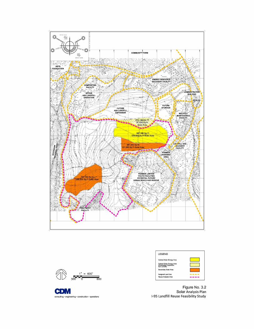
3.2 Solar Photovoltaic Analysis
Based on the 2008 Existing Conditions Survey, CDM conducted a conceptual solar photovoltaic (PV)
analysis of the site. Figure 3.2 identifies the Optimal and Secondary Solar Energy Areas. The northern
portion of the Optimal Solar Energy Area should be considered temporary and its value based on the
Ash Landfill expansion schedule. In general, the optimal site area was selected based on a south
orientation and slopes in the 5-10 percent range.
For a fixed mount solar system, panels are ideally mounted south facing at an angle equal to the site’s
latitude, which for Lorton, VA is 39 degrees from the horizontal. Based on this site’s capped topography,
significant surface modifications, including cap penetrations, would be required to establish slopes that
would achieve a 39 degree angle. Therefore, achieving a 39 degree angle is not considered feasible. A
ballasted (non-penetrative) type PV mounting system is recommended for the Optimal Solar Energy
Areas of the landfill. This type system would utilize concrete blocks to hold the PV mounting structure in
place, thus eliminating the need for ground penetration supports. The mounting angle for these types of
systems usually ranges from zero to twenty degrees, with the greater angle producing more output. The
final angle would be determined based on geotechnical and structural analysis.
There are two main types of solar PV technologies – crystalline cells and thin film solar cells. Historically,
crystalline cells have been more widely used and comprise over 90% percent of the total market share
of solar cell technologies. Crystalline cells are convenient because stable solar cells with good
efficiencies can be produced. Thin film solar cells are generally believed to have lower efficiencies than
crystalline cells, but have a slightly lower installed cost per watt (W). Research suggests that thin film
solar cells will be a likely competitor to crystalline solar cells in the future, as advances in efficiency and

absorption of a broader range of light are expected. Based on project solar production goals and budget,
crystalline was used for this study based on the higher efficiency of this technology and estimated
overall cost per watt of the panel.
The solar panel used for the analysis is a 240W panel, which is approximately 69” X 39.5” or
approximately 18 square feet (sqft). This results in a power density of 13.33W/sqft. Although there are
more efficient panels available, this is a mid-to-high grade panel and there are many similar modules on
the market around this wattage and size, providing for price competition and availability. Based on the
proposed power density and previous project design experience, for planning purposes we used the
one-third approximation. This approximation assumes one third of the identified area is available for
solar panels. The other two-thirds area is remaining for shading, maintenance, ancillary equipment,
walkway and or roadways. Using Figure 3.2, and based on the above assumptions, design criteria, and a
ten degree mounting angle, the estimated Solar PV system sizes are listed below.
Solar Energy Potential
Site Footprint (sq ft) Solar Potential (kW) Annual Production (kWh)
Optimal Solar Energy 987,086 4,386 5,248,969
Optimal Solar Energy (Future) 272,139 1,209 1,446,877
Secondary Solar Area 1 381,923 1,697 2,030,893
Secondary Solar Area 2 797,180 3,542 4,238,906
This proposed solar PV system used for this study is a utility interactive type system, meaning the output
of the system will be compatible with the Energy from Waste facility and or electric utility AC power. It
is assumed that no batteries will be used to store power. Further electrical interconnection
coordination with the Energy from Waste and electric utility is necessary and would be completed
during a more detailed study and the design phase.
For planning purposes, total turn-key pricing, including design, permitting, materials and construction
for this size system will be approximately $5 to $5.5 per watt.
3.3 Drainage Analysis
The drainage system for the I-95 Landfill (Figure 3.3) and associated facilities consists of vegetated
swales, rip rap down chutes, and several detention basins. The detention basins are primarily outside
the limits of the reuse analysis area. Vegetated swales are located on the uphill side of the landfill
maintenance roadways and are an integral part of the erosion control system. The optimal areas for
reuse are located on the higher elevations and slopes less than 15-percent. In these areas the vegetated
swales are spaced farther apart, allowing access and the space required for reuse. The vegetated swales
in this area could also be modified to meet reuse needs with minimal impact to the overall closure.
Modification of the vegetated swales on the steeper slopes is not recommended. Modifications to the
rip rap down chutes are also not recommended.

3.4 Landfill Gas Collection Analysis
The landfill gas collection system consists of a series of vertical wells spaced across the closed MSW
disposal area, with some horizontal wells located around the closure cap perimeter as shown on Figure
3.4. The gas is extracted from the wells and collected by a system of header pipes, then sent to the
Landfill Gas Recovery Facility to fuel engines that produce electricity. For the purposes of this study, it is
assumed that the landfill gas system will remain in operation during the majority of the interim reuse
period. While the system does represent a constraint, there are system modifications that can be made
to accommodate reuse alternatives. The primary concerns are protecting the operating system from
damage and preventing non-landfill personnel from potential exposure. The existing riser pipes could
be removed and the control values placed in a locked vault at or below grade. The collection header
pipes would require protection from puncture from any reuse alternative that requires penetration
below the existing final cap system. They would also require protection from high loadings and localized
settlement that could result in excessive strains or breakage. If in the future it can be demonstrated
that the system is no longer required for post-closure operations, the landfill gas system may ultimately
be decommissioned depending on the long-term reuse alternative(s) selected.
3.5 Settlement Analysis
CDM reviewed the final grading drawings for the Phase II Closure and compared the elevations with the
2008 survey. The results of this comparison are found in Figure 3.5. The comparison was completed on a
250-ft. grid. Sporadic areas of minor settlement in the 1-ft to 2-ft range were evident but these
appeared primarily in areas outside of the Optimal Energy Areas for reuse identified from the earlier
analysis. CDM also reviewed the Record Drawings for the Phase III and Phase IV Closure. In the
summary meeting, County staff noted there were isolated areas of settlement northwest of the
administration area. No areas of settlement were visible, based on the comparison of the Closure
documents and the 2008 survey. It should be noted that the closure documents and record drawings
were dated 2006 and 2009, which is not an effective basis for comparison. Settlement would be
expected in these areas, and depending on the reuse, another survey or settlement monitoring program
should be advanced prior to further evaluations. CDM recommends a new topographic survey in these
areas and a digital comparison with the 2008 Existing Conditions Survey.
Recommended Areas for Reuse Comparing the various site analysis figures and the optimal area from each analysis, CDM developed
Figure 4.1 showing the recommended areas for reuse. Potential access points and recommended access
routes are also identified. The first consists of approximately 65 acres and is at the higher elevations and
more level portions of the reuse area. An access point south of the Landfill Gas Recovery Facility could
be utilized, minimizing impact on the adjacent activities. This area also has a number of existing
maintenance roadways that could be utilized. Since this is currently a very visible portion of the landfill,
the visual impacts of any proposed reuse should be considered.

The second area consists of 20 acres and is located in the valley southwest of the former Lorton Youth
Facilities. Access to this location could also be from the entrance south of the Landfill Gas Recovery
Facility and the southern landfill maintenance roadway. This location has very low visibility from
adjacent land uses and has the lowest impact on the County’s active site activities.
A third area consists of approximately 3 acres and is located northwest of the Ash Landfill. Although it is
located outside the reuse analysis area, it should be considered based on its level topography and
proximity to an access point located off the Occoquan Regional Park access road.
Opportunities and Constraints Based on the information and analysis presented above, as well as discussions with County staff, CDM
developed a summary of potential landfill reuse options as shown in Figure 5.1. The options highlighted
in green represent those that are currently considered feasible. The options highlighted in yellow
represent those that could be considered in the future as the active operations at the site phase out.
Those options highlighted in red were not considered as part of this limited study.
A list of Opportunities and Constraints were identified and are highlighted in blue along the top of Figure
5.1. Analyzing each reuse option against each opportunity/constraint, a table was developed which will
assist the County in assessing the feasibility of any particular reuse option.
At this point, no specific reuse option(s) have been finalized for implementation. However, during the
site analysis review workshop held with County staff, the most desirable options appear to include:
Renewable Energy (Solar);
Container Nursery or contract growing of plant material above the landfill cap;
Vehicle/Boat/RV storage; and,
Materials Storage.
Once the County has reviewed these potential options with the other landfill partners, a more detailed
analysis to evaluate design issues, implementation costs, and additional stakeholder input should be
performed to develop a final list of reuse options.


![Index [zerowasteeurope.eu] · The E U Landfill Directive 1 ... the EU waste management system as a whole, while working collaboratively towards waste reduction, increasing reuse](https://img.dokumen.tips/doc/110x75/6026e632d879a037df70ec07/index-the-e-u-landfill-directive-1-the-eu-waste-management-system-as-a-whole.jpg)


![Landfill Reuse White Paper [Case Study]](https://img.dokumen.tips/doc/110x75/587e0a791a28abe11a8b6b37/landfill-reuse-white-paper-case-study.jpg)


