Embed Size (px)
Citation preview

vertical express
I-2® / I-3® Valve

Every attempt has been made to ensure that this documentation is as accurate and up-to-date as possible.However, Vertical Express assumes no liability for consequences, directly or indirectly, resulting from any error oromission. The material contained herein is subject to revision. Please report any problems with this manual to
Vertical Express, P.O. Box 2019, Memphis, Tennessee 38101.
Vertical Express • P.O. Box 2019 • Memphis, Tennessee 38101
© 2005, 2011 Vertical Express. All rights reserved.Published May, 2012
Second Edition Printed in the United States of America
Manual Number: 89130 v.2.0

I-2 / I-3 Valve Contents
Printed in USA May, 2012 1
I-2 / I-3 Valve
Contents
Safety Precautions . . . . . . . . . . . . . . . . . . . . . . . . . . . . . . . . . . . . . . . . . . . . . . . . . . . . . . . . . . . . . . . . 3
General Safety . . . . . . . . . . . . . . . . . . . . . . . . . . . . . . . . . . . . . . . . . . . . . . . . . . . . . . . . . . . . . 3
Electrical Safety . . . . . . . . . . . . . . . . . . . . . . . . . . . . . . . . . . . . . . . . . . . . . . . . . . . . . . . . . . . . 3
Mechanical Safety . . . . . . . . . . . . . . . . . . . . . . . . . . . . . . . . . . . . . . . . . . . . . . . . . . . . . . . . . . 4
Arrival of Equipment . . . . . . . . . . . . . . . . . . . . . . . . . . . . . . . . . . . . . . . . . . . . . . . . . . . . . . . . . 5
Preliminary Settings . . . . . . . . . . . . . . . . . . . . . . . . . . . . . . . . . . . . . . . . . . . . . . . . . . . . . . . . . . . . . . . 7
Oil Viscosity and Viscosity Control . . . . . . . . . . . . . . . . . . . . . . . . . . . . . . . . . . . . . . . . . . . . . . . 7
Relief Pressure Setting . . . . . . . . . . . . . . . . . . . . . . . . . . . . . . . . . . . . . . . . . . . . . . . . . . . . . . . 7
Low Pressure Setting . . . . . . . . . . . . . . . . . . . . . . . . . . . . . . . . . . . . . . . . . . . . . . . . . . . . . . . . 8
Lowering and Leveling Speed Setting . . . . . . . . . . . . . . . . . . . . . . . . . . . . . . . . . . . . . . . . . . . . 9
Quick Reference Guide for Valve Adjustments . . . . . . . . . . . . . . . . . . . . . . . . . . . . . . . . . . . . . . . . . . . 10
Preliminary Adjustments . . . . . . . . . . . . . . . . . . . . . . . . . . . . . . . . . . . . . . . . . . . . . . . . . . . . . . . . . . . 11
Relief Pressure Adjustment . . . . . . . . . . . . . . . . . . . . . . . . . . . . . . . . . . . . . . . . . . . . . . . . . . . 11
Slowdown and Leveling Speed Adjustment . . . . . . . . . . . . . . . . . . . . . . . . . . . . . . . . . . . . . . . 12
Final Adjustments . . . . . . . . . . . . . . . . . . . . . . . . . . . . . . . . . . . . . . . . . . . . . . . . . . . . . . . . . . . . . . . . 14
Valve-Up Section . . . . . . . . . . . . . . . . . . . . . . . . . . . . . . . . . . . . . . . . . . . . . . . . . . . . . . . . . . 14
Valve-Down Section . . . . . . . . . . . . . . . . . . . . . . . . . . . . . . . . . . . . . . . . . . . . . . . . . . . . . . . . 15
Performance Check with Full Load. . . . . . . . . . . . . . . . . . . . . . . . . . . . . . . . . . . . . . . . . . . . . . 16
Final Relief Pressure with Full Load . . . . . . . . . . . . . . . . . . . . . . . . . . . . . . . . . . . . . . . . . . . . . 16
Troubleshooting Table
Up Operation . . . . . . . . . . . . . . . . . . . . . . . . . . . . . . . . . . . . . . . . . . . . . . . . . . . . . . . . . . . . . 17
Down Operation . . . . . . . . . . . . . . . . . . . . . . . . . . . . . . . . . . . . . . . . . . . . . . . . . . . . . . . . . . 18
Replacement Parts . . . . . . . . . . . . . . . . . . . . . . . . . . . . . . . . . . . . . . . . . . . . . . . . . . . . . . . . . . . . . . . 19
Reference Material . . . . . . . . . . . . . . . . . . . . . . . . . . . . . . . . . . . . . . . . . . . . . . . . . . . . . . . . . . . . . . . 20
Troubleshooting Flowcharts . . . . . . . . . . . . . . . . . . . . . . . . . . . . . . . . . . . . . . . . . . . . . . . . . . 20
Sequence of Events . . . . . . . . . . . . . . . . . . . . . . . . . . . . . . . . . . . . . . . . . . . . . . . . . . . . . . . . 52

Contents I-2 / I-3 Valve
2 Vertical Express
This page
intentionally
left blank.

Safety Precautions I-2 / I-3 Valve
3Printed in USA May, 2012
Safety Precautions
IMPORTANT! Read this page before any work is performed on elevator equipment. The procedures contained in this manual are intended for the use of qualified elevator personnel. In the interest of your personal safety and the safety of others, do not attempt any procedure that you are not qualified to perform.
All procedures must be accomplished in accordance with the applicable rules in the latest edition of the National Electrical Code, the latest edition of ASME A17.1, and any governing local codes.
Terms in This Manual
CAUTION statements identify conditions that may result in damage to the equipment or other property if improper procedures are followed.
WARNING statements identify conditions that may result in personal injury if improper procedures are followed.
General Safety
Before applying power to the controller, check that all factory wire connections are tight on relays, contactors, fuse blocks, resistors, and terminals on cards and DIN rail terminals. Connections loosened during shipment may cause damage or intermittent operation.
Other specific warnings and cautions are found where applicable and do not appear in this sum-mary. See the Elevator Industry Field Employees’ Safety Handbook for electrical equipment safety information on installation and service.
Electrical Safety All wiring must be in accordance with the National Electrical Code and be consistent with all state and local codes.
Use the Proper Fuse
To avoid fire hazards, use only a fuse of the correct type, voltage, and current rating. See the job specific drawings sheet (Power Supplies) for fusing information.
Electric shocks can cause personal injury or loss of life. Circuit breakers, switches, and fuses may not disconnect all power to the equipment. Always refer to the wiring diagrams. Whether the AC supply is grounded or not, high voltage will be present at many points.
Printed Circuit Cards
Printed circuit boards may be damaged if removed or installed in the circuit while applying power. Before installation and/or removing printed circuit boards, secure all power.
Always store and ship printed circuit cards in separate static bags.

I-2 / I-3 Valve Safety Precautions
4 Vertical Express
(continued)(continued)Electrical Safety Mainline Disconnect
Unless otherwise directed, always Turn OFF, Lock, and Tag out the mainline disconnect to remove power from elevator equipment. Before proceeding, confirm that the equipment is de-energized with a volt meter. Refer to the Elevator Industry Field Employees’ Safety and Accident Prevention Program Manual for the required procedure.
Test Equipment Safety
Always refer to manufacturers’ instruction book for proper test equipment operation and adjust-ments.
Megger or buzzer-type continuity testers can damage electronic components. Connection of devices such as voltmeters on certain low level analog circuits may degrade electronic system per-formance. Always use a voltmeter with a minimum impedance of 1M Ohm/Volt. A digital voltmeter is recommended.
When Power Is On
To avoid personal injury, do not touch exposed electrical connections or components while power is ON.
Mechanical Safety See the Elevator Industry Field Employees’ Safety Handbook for mechanical equipment safety information on installation and service.

Safety Precautions I-2 / I-3 Valve
5Printed in USA May, 2012
Static Protection Guidelines
IMPORTANT! Read this page before working with electronic circuit boards.
Elevator control systems use a number of electronic cards to control various functions of the elevator. These cards have components that are extremely sensitive to static electricity and are susceptible to damage by static discharge.
Immediate and long-term operation of an electronic-based system depends upon the proper handling and shipping of its cards. For this reason, the factory bases warranty decisions on the guidelines below.
Handling • Cards shipped from the factory in separate static bags must remain in the bags until time for installation.
• Anti-static protection devices, such as wrist straps with ground wire, are required when handling circuit boards.
• Cards must not be placed on any surface without adequate static protection.
• Only handle circuit cards by their edges, and only after discharging personal static electricity to a grounding source. DO NOT touch the components or traces on the circuit card.
• Extra care must be taken when handling individual, discrete components such as EPROMS (which do not have circuit card traces and components for suppression).
Shipping • Complete the included board discrepancy sheet.
• Any card returned to the factory must be packaged in a static bag designed for the card.
• Any card returned to the factory must be packaged in a shipping carton designed for the card.
• “Peanuts” and styrofoam are unacceptable packing materials.
Note: Refer to the Vertical Express Replacement Parts Catalog to order extra static bags and shipping cartons for each card.
Failure to adhere to the above guidelines will VOID the card warranty!
Arrival of Equipment Receiving
Upon arrival of the equipment, inspect it for damage. Promptly report all visible damage to the carrier. All shipping damage claims must be filed with the carrier.
Storing
During storage in a warehouse or on the elevator job site, precautions should be taken to protect the equipment from dust, dirt, moisture, and temperature extremes.
Handling
The door operator is packaged in a cardboard box and crated. If possible, leave completely crated when handling.

I-2 / I-3 Valve Safety Precautions
6 Vertical Express
This page
intentionally
left blank.

I-2 / I-3 Valve Preliminary Settings
Printed in USA May, 2012 7
Preliminary Settings
Oil Viscosity and Viscosity Control
• The power unit should be located in a room that is ventilated and heated between 500F and 900F.
• Adjust the valve when the oil is at its operating temperature of 1000F to 1700F.
• Ensure that the unit performance is checked when the oil temperature is at minimum heated range of 1000F or above.
• Changes in oil temperature will cause changes in valve behavior.
Be EXTREMELY careful when making adjustments near moving belts. When operating the elevator from the controller, follow all safety precautions.
Relief Pressure Setting
The I-2/I-3 Valve requires a minimum static system pressure of 90 PSI.
1. Ensure that the car is empty.
2. Turn OFF, Lock, and Tag out the mainline disconnect.
3. Lower the car onto the buffers by opening the manual lowering valve. See Figure 1.
4. Close the manual lowering valve.
5. Install a pressure gauge on the quick connector (located on the far side of the valve).
6. Turn the relief pressure adjustment screw OUT until 5/8” extends beyond the relief assembly housing, and tighten the locknut.
Figure 1 - Relief Pressure Setting
Relief PressureAdjustment
ManualLowering Valve
Up LevelingAdjustment
5/8”

Preliminary Settings I-2 / I-3 Valve
8 Vertical Express
Preliminary Settings(continued)
Low Pressure Setting
Note: OUT = Counterclockwise, CCWIN = Clockwise, CW
1. Turn the low pressure adjustment screw OUT 1 3/4” beyond the cover plate. See Figure 2.
2. Turn the low pressure adjustment screw IN by hand until it touches the regulator piston.
3. Turn the up leveling adjustment screw OUT until it stops.
4. Turn the up leveling adjustment screw IN four (4) turns.
Adjustment Needles
Note: To make adjustments, do not loosen the nuts on the adjustment needle stems. They should be snug against the valve body at all times.
1. Turn the up start, up stop, and up slowdown adjustment needles IN to the fully closed position. See Figure 2.
2. Turn the up start needle OUT nine (9) turns.
3. Turn the up stop needle OUT three (3) turns.
Note: The up slowdown needle should remain closed.
Figure 2 - Low Pressure Setting
Low PressureAdjustment
Up LevelingAdjustment
Up SlowdownAdjustmentUp Stop
AdjustmentUp StartAdjustment
Down StopAdjustment
Lowering & LevelingSpeed Adjustment
Down StartAdjustment
Down SlowdownAdjustment

I-2 / I-3 Valve Preliminary Settings
Printed in USA May, 2012 9
Lowering and Leveling Speed Setting
To avoid damage to the piston face and seat, never turn the lowering and leveling speed adjustment unless the car is resting on the buffers or the car is in motion.
1. With the car set on the buffers, adjust the lowering and leveling screw so that 3/4“ extends beyond the valve body. See Figure 3.
2. Make sure the flat end of the screw is pointed 450F counterclockwise to the tank return line.
3. Tighten the locknut.
Figure 3 - Lowering and Leveling Speed Setting
Adjustment Needles
Note: To make adjustments, do not loosen the nuts on the adjustment needle stems. They should be snug against the pilot body assembly at all times.
1. Turn the down start, down stop, and the down slowdown adjustment IN to the fully closed position.
2. Turn the down start adjustment OUT nine (9) turns.
3. Turn the down stop adjustment OUT ten (10) turns.
Note: The down slowdown adjustment must remain closed at this time.
Tank Return Line
3/4”
45º
Flat End of Screw

Quick Reference Guide for Valve Adjustments I-2 / I-3 Valve
10 Vertical Express
Quick Reference Guide for Valve Adjustments
VALVE
AD
JUSTM
ENT
EFFECTS
SLOW
DO
WN
STOP
SLOW
DO
WN
START
START
STOP
UP
PILOT
DO
WN
PILOT
IN=
SM
OO
THER
STA
RT
(MAY
LIMIT
HIG
HS
PEED
INCO
NJU
NC
TION
WITH
STO
P)
DO
ESN
OT
AFFEC
TS
TOP
IN=
SO
FTERS
TOP
&FIR
MER
STA
RT
AFTER
PR
OP
ERLEV
ELING
SP
EEDIS
SET,TH
ENFIN
ETU
NE
STO
P,THEN
FINE
TUN
ES
TAR
T
IFS
ETTO
OS
OFT
MAY
OV
ERS
HO
OT
FLOO
R
IN=
SH
OR
TERLEV
ELING
ZON
E*
IN=
SO
FTERS
LOW
DO
WN
SEN
SITIV
EA
DJU
STM
ENT
IN=
INC
REA
SE
INLEV
ELING
SP
EED
IN=
SM
OO
THER
STA
RT
HA
SN
OEFFEC
TO
NO
THER
AD
JUS
TMEN
TS
SET
ITFIR
ST
AN
DD
ON
OT
CH
AN
GE.
AFFEC
TSA
LLD
OW
NS
IDE
AD
JUS
TMEN
TS
IN=
SO
FTERS
TOP
IN=
LOW
ERS
LEVELIN
GS
PEED
IN=
INC
REA
SES
LEVELIN
GZO
NE**
IN=
MO
RE
AB
RU
PT
SLO
WD
OW
NLO
WPRESSU
RE
UP
LEVELING
DO
WN
SPEED&
DO
WN
LEVELING
PIS
TON
IN=
CLO
SES
REG
ULATO
R
&S
OFTEN
SS
LOW
DO
WN
IN=
INC
REA
SES
LEVELIN
GS
PEED
IN=
INC
REA
SES
RELIEF
PR
ESS
UR
E
RELIEF
CA
N’T
AD
JUS
TW
ITHLO
AD
ON
THE
PIS
TON
- THE C
AR
MU
ST B
EM
OV
ING
UP
OR
DO
WN
OR
ON
BU
FFERS
.
IN=
RED
UC
ESS
PEED
(HIG
HD
OW
NS
PEED
MU
ST B
E AD
JUS
TEDIN
1/2TU
RN
S)
FOR
LEVELIN
G -
AD
JUS
TMEN
TIS
VERY S
ENS
ITIVE - U
SE
SM
ALL
INC
REM
ENTS
**D
OW
NLEV
ELING
ISA
FFECTED
BY D
OW
N S
LOW
DO
WN
- REC
HEC
KLEV
ELING
AFTER
MA
KIN
G FIN
AL
SLO
WD
OW
N S
ETTING
UP
FAST
UP
SLOW
DO
WN
SLOW
DO
WN
FAST
MA
NU
AL
LOW
ERING
IN=
CLO
SES
VER
YS
ENS
ITIVE
AD
JUS
TMEN
T,SET
ITLA
ST
IN=
FIRM
ERS
TAR
TIN
=S
MO
OTH
ERS
LOW
DO
WN
IN=
HIG
HER
LEVELIN
GS
PEED
MU
ST
BE
MO
RE
OP
ENTH
AN
UP
STO
P
*U
PLEVELIN
GA
ND
UP
SLOW
DO
WN
AFFECT
EACH
OTH
ER.W
HEN
ON
E IS CHA
NG
ED,
THE O
THER IS A
LSO CH
AN
GED
.

I-2 / I-3 Valve Preliminary Adjustments
Printed in USA May, 2012 11
Preliminary Adjustments
When operating the elevator from the controller, follow all safety precautions.
1. Ensure that the car is empty and the manual lowering valve is closed.
2. Turn OFF, Lock, and Tag out the mainline disconnect.
3. Disable the up slow solenoid by disconnecting the solenoid wire from the controller. See the appropriate controller diagrams.
4. Disable the up fast solenoid by placing the controller on Inspection Operation.
Note: The type of controller will determine how Inspection Operation is accomplished.
5. Turn the power on, and start the motor.
6. Turn the low pressure adjustment IN just until the car starts to move.
7. Turn the low pressure adjustment OUT until the car movement stops.
8. After the car stops, turn the low pressure adjustment OUT an additional one-half (1/2) turn.
9. Use these instructions on valves marked with SP on the cover plate or the valve nameplate:
Note: The car must be stopped and started to check the setting.
a. Turn the low pressure adjustment OUT three (3) turns.
b. Check for too much time delay between the motor starting and the car movement.
c. Turn the low pressure adjustment IN until excessive delay is eliminated.
10. Tighten the locknut.
11. Stop the motor, and turn the power off.
12. Remove any jumpers that may have been used.
13. Reconnect the up slow solenoid wire to the controller.
Relief Pressure Adjustment
1. Close the line shut-off valve, and install a pressure gauge.
2. With the controller on Inspection Operation, turn the power on, start the motor, and read the pressure.
Stop the power unit IMMEDIATELY if pressure exceeds 625 PSI.
3. Adjust the relief valve to relieve at the pressure indicated on the power unit nameplate. See Figure 4 on page 12.
4. Tighten the locknut, and Turn OFF, Lock, and Tag out the mainline disconnect.
5. Relieve the jack pressure by opening the manual lowering valve.
6. Close the manual lowering valve.
Preliminary Adjustments I-2 / I-3 Valve
12 Vertical Express
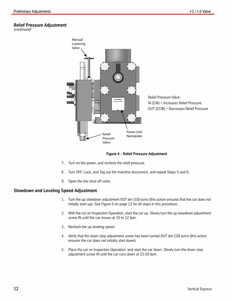
Relief Pressure Adjustment(continued)
Figure 4 - Relief Pressure Adjustment
7. Turn on the power, and recheck the relief pressure.
8. Turn OFF, Lock, and Tag out the mainline disconnect, and repeat Steps 5 and 6.
9. Open the line shut-off valve.
Slowdown and Leveling Speed Adjustment
1. Turn the up slowdown adjustment OUT ten (10) turns (this action ensures that the car does not initially start up). See Figure 5 on page 13 for all steps in this procedure.
2. With the car on Inspection Operation, start the car up. Slowly turn the up slowdown adjustment screw IN until the car moves at 10 to 12 fpm.
3. Recheck the up leveling speed.
4. Verify that the down stop adjustment screw has been turned OUT ten (10) turns (this action ensures the car does not initially start down).
5. Place the car on Inspection Operation, and start the car down. Slowly turn the down stop adjustment screw IN until the car runs down at 15-20 fpm.
Power Unit NameplateRelief
Pressure Valve
Manual LoweringValve
Relief Pressure Valve:
IN (CW) = Increases Relief Pressure
OUT (CCW) = Decreases Relief Pressure

I-2 / I-3 Valve Preliminary Adjustments
Printed in USA May, 2012 13
Slowdown and Leveling Speed Adjustment(continued)
6. Turn the lowering and leveling speed adjustment by less than one-quarter turn increments, to adjust the leveling speed to 10-12 fpm. Pause between each change.
Note: If the lowering and leveling speed adjustment is turned too far (more than one-quarter turn) the car will lock in the down direction. If this happens, run the car up on Inspection Operation while another person in the machine room turns the lowering and leveling speed adjustment screw OUT a small amount.
7. Tighten the locknut.
8. If the car does not stop, turn the down stop adjustment screw OUT until the stop is positive.
9. Recheck the down leveling speed.
Figure 5 - Slowdown and Leveling Speed Adjustment
Low PressureAdjustment
Up LevelingAdjustment
Up SlowdownAdjustmentUp Stop
AdjustmentUp StartAdjustment
Down StopAdjustment
Lowering & LevelingSpeed Adjustment
Down StartAdjustment
Down SlowdownAdjustment

Final Adjustments I-2 / I-3 Valve
14 Vertical Express
Final Adjustments The manufacturing presets of the valve adjustments are attached to the inside of the controller. These values ensure movement of the car and also reduce final adjustment time. Perform these adjustments in the order given because they affect each other.
To be adjusted, the I-2/I-3 Valve requires a minimum static system pressure of 90 PSI.
Valve-Up Section Up Slowdown and Up Leveling Speed
1. Verify that the car is empty.
2. Place the controller on Automatic Operation, and send the car to the lowest landing.
3. Run the car to the floor above and observe the leveling zone.
4. Adjust the up slowdown for 3 to 4 inches of leveling.
Each time the up slowdown is adjusted, the up leveling speed must be rechecked.
5. Run the car on Inspection Operation, and adjust the up leveling speed adjuster. The leveling speed should be 10-12 fpm.
When operating the car from the controller, ensure all safety precautions are followed.
6. Place the car on Automatic Operation.
7. Check the leveling zone for 3 to 4 inches, and the leveling speed for 10 to 12 fpm.
8. Continue to adjust the up slowdown needle and the up leveling adjuster until the desired performance is achieved.
Up Stop and Up Start
Because the up stop adjustment affects the up start adjustment, it must be adjusted first.
1. Adjust the up stop for a soft but positive stop.
2. Adjust the up start for a smooth but positive start.
3. Check to be certain full up speed is reached on a one-floor run, which may require the up start to be more positive.
4. Slightly alter the slowdown adjustment to achieve optimum performance, if necessary.
Up Slowdown - Adjust for 3 to 4 inches of Leveling
IN (cw)
Shorten Leveling Zone
Increase Leveling Speed
Softer Up Slowdown
Up Leveling -10 to 12 fpm
IN (cw)Increase Leveling Speed
Softer Up Slowdown
IN (cw)
Up Stop Up Start
Stop Softer Start Smoother
Start Firmer Limit High Speed

I-2 / I-3 Valve Final Adjustments
Printed in USA May, 2012 15
Valve-Down Section Lowering Speed
1. Place the car on Automatic Operation.
2. Set the lowering speed.
a. Use an empty car, and turn the lowering speed adjustment in one-half turn increments.
b. After each adjustment, leave the flat end of the screw pointed 450F to the tank return line.
If no speed change occurs with one full turn on the lowering speed adjuster, DO NOT CONTINUE TO TURN IT OUT. Check for a stop open wider than a start, or a mechani-cal piston binding.
Down Leveling Speed and Down Stop
The down leveling speed and the down stop adjustment must be performed together since the down stop adjustment affects the down leveling speed. The down leveling speed, however, does not affect the down stop adjustment.
1. Place the controller on Inspection Operation.
2. Adjust the down stop for a positive stop.
3. Adjust the down leveling speed to 10-12 fpm.
4. Tighten the locknut on the down leveling speed adjustment.
5. Recheck the down leveling speed.
Down Start
1. Place the controller on Automatic Operation.
2. Adjust the down start adjustment to obtain a smooth start.
Note: Ensure that the car achieves full speed on a one-floor run. If not, make the down start more positive.
Lowering Speed
OUT (ccw)One-half Turn Increments
Increase Lowering Speed
Down Stop
IN (cw)Stop Softer
Increase Leveling Speed
Down Leveling Speed
OUT (ccw)Less than one-quarter turn increments
Increase Leveling Speed
Down Start
IN (cw) Start Smoother

Final Adjustments I-2 / I-3 Valve
16 Vertical Express
Valve-Down Section(continued) Down Slowdown
The effect of the down slowdown adjustment is the opposite of the previous adjustments. Turning OUT on the down slowdown adjustment will shorten the leveling zone. Turning IN on the down slow-down adjustment will lengthen the leveling zone. Make this adjustment in small increments as soon as a change is observed in the leveling zone. The car will overshoot the landing if the adjustment is turned OUT too far.
1. Turn the down slowdown adjustment OUT in small increments until the car has a leveling zone of 3 to 4 inches.
2. It may be necessary to slightly alter the point in the hoistway where the slowdown is initiated to achieve optimum valve and car performance.
Note: This action is usually accomplished by either switch location or selector settings.
Performance Check with Full Load
1. Place a capacity load on the car.
2. Run the car on Automatic Operation, and the check performance at all floors. All valve functions will become firmer at upper landings. If adjustments are necessary, it will affect the empty car performance.
Notes:
• The down leveling speed will increase and the down leveling zone will be shorter. It may be necessary to change the down slowdown adjustment to be certain there is at least two (2) inches of leveling.
• If necessary, turn IN on the down slowdown to increase the leveling zone.
• The up leveling speed will increase. The up leveling zone will change between no load and full load. Do not change any adjustments made with no load if there is at least one (1) inch of up leveling zone with a full load.
• If necessary, turn OUT on the up slowdown adjustment to increase the up leveling zone.
3. Verify that the car is obtaining full speed in both directions on a one-floor run.
4. Record the working pressure in the up direction.
Note: The working pressure value will be used in the next procedure.
5. Remove the capacity load from the car.
Final Relief Pressure with Full Load
1. Place the controller on Inspection Operation, and close the line shut-off valve.
2. Start the pump, and read the relief pressure.
3. Add 25% to the working pressure recorded in Step 4 of the previous procedure, and set the relief valve to relieve at this new pressure value.
4. Stop the power unit, and tighten the locknut on the relief pressure adjustment.
5. Recheck the relief pressure.
Stop the power unit IMMEDIATELY if pressure exceeds 625 PSI.
6. Open the line shut-off valve, and place the car on Automatic Operation.

I-2 / I-3 Valve Troubleshooting Table - Up Operation
Printed in USA May, 2012 17
Troubleshooting Verify the following list before using the troubleshooting tables. See also “Troubleshooting Flowcharts” in the reference material section starting on page 20.
1. No binding in the hoistway.
2. The proper voltage is being supplied to the power unit.
3. All valve adjustments have been completed as recommended.
4. All vee belts on the power unit have the proper tension.
5. There is no oil on the belts to cause slippage.
Troubleshooting Table - Up Operation
Problem Solution
Pump runs, but the car does not run at high speed. 1. Check that the line shut-off valve is fully open.
2. Check for the correct motor rotation.
3. Check for the correct relief pressure setting.
4. Check that the up fast solenoid pulls IN.*
5. Turn OUT on the up start adjustment.
6. Turn IN on the up stop adjustment.
7. Make sure that the regulator piston is free.
8. Make sure that the up pilot piston is free.
Car will not slowdown to leveling speed. 1. Check that the up slow solenoid pulls IN.*
2. Check that the up fast solenoid drops OUT.*
3. Turn OUT on the up slowdown adjustment.
4. Check the up leveling speed. Set for 10 to 12 fpm.
5. Make sure that the regulator piston is free.
6. Make sure that the pressure control piston is free.
Car will not make a hydraulic stop. 1. Check that the up slow solenoid drops OUT.*
2. Check for the correct low pressure adjustment.
3. Turn OUT the up stop adjustment.
4. Make sure that the regulator piston is free.
5. Make sure that the up pilot piston is free.
Acceleration, deceleration, leveling speed, or stop is erratic.
1. Make sure that the check valve piston is free.
2. Make sure the spring on the regulator piston does not bind.
Leveling speed slows down or car stalls after slowdown (check if releveling speed slows down).
1. Turn IN on the slowdown adjustment.2. Replace the leveling adjuster/strainer.
* Check the solenoids for voltage and for damage to the solenoid tube. Check the plunger for binding. Do not reseat. If the seat in the pilot body is damaged, replace the pilot.
Troubleshooting Table - Down Operation I-2 / I-3 Valve
18 Vertical Express
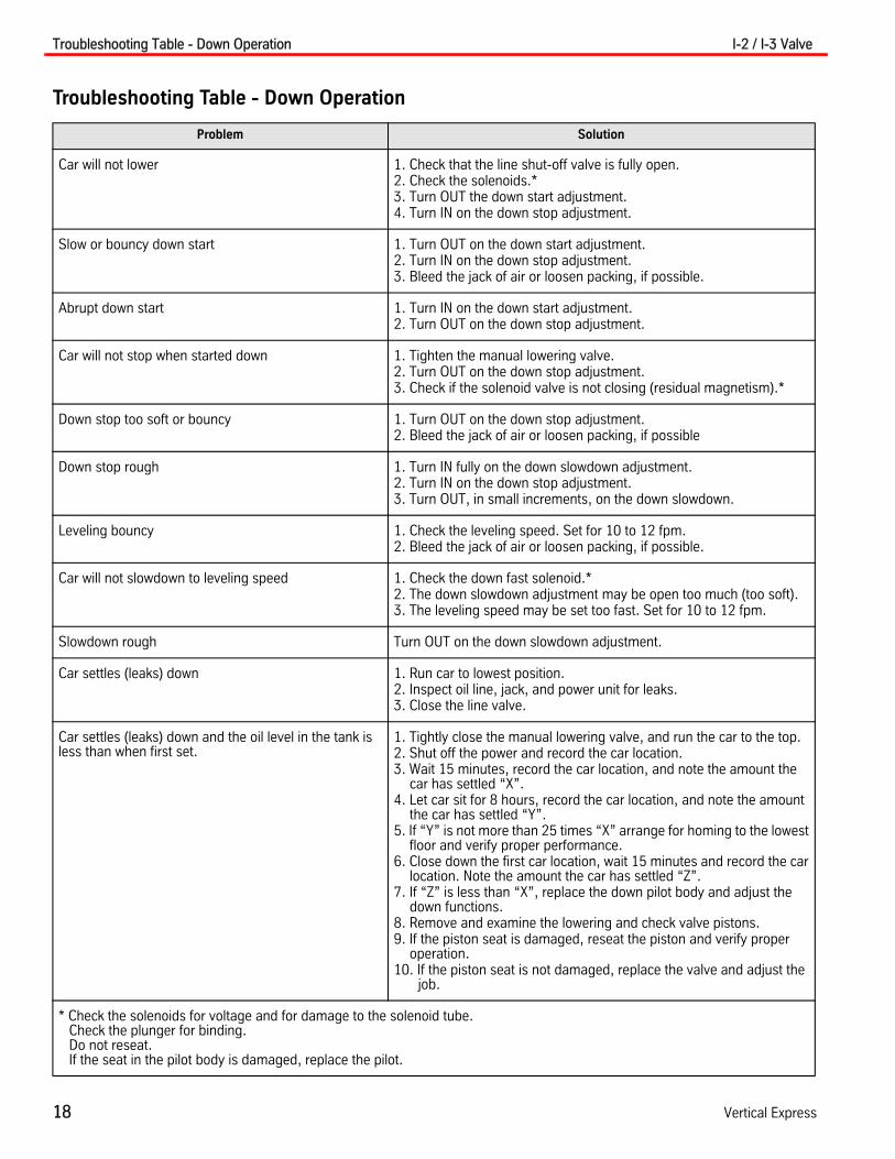
Troubleshooting Table - Down Operation
Problem Solution
Car will not lower 1. Check that the line shut-off valve is fully open.2. Check the solenoids.*3. Turn OUT the down start adjustment.4. Turn IN on the down stop adjustment.
Slow or bouncy down start 1. Turn OUT on the down start adjustment.2. Turn IN on the down stop adjustment.3. Bleed the jack of air or loosen packing, if possible.
Abrupt down start 1. Turn IN on the down start adjustment.2. Turn OUT on the down stop adjustment.
Car will not stop when started down 1. Tighten the manual lowering valve.2. Turn OUT on the down stop adjustment.3. Check if the solenoid valve is not closing (residual magnetism).*
Down stop too soft or bouncy 1. Turn OUT on the down stop adjustment.2. Bleed the jack of air or loosen packing, if possible
Down stop rough 1. Turn IN fully on the down slowdown adjustment.2. Turn IN on the down stop adjustment.3. Turn OUT, in small increments, on the down slowdown.
Leveling bouncy 1. Check the leveling speed. Set for 10 to 12 fpm.2. Bleed the jack of air or loosen packing, if possible.
Car will not slowdown to leveling speed 1. Check the down fast solenoid.*2. The down slowdown adjustment may be open too much (too soft).3. The leveling speed may be set too fast. Set for 10 to 12 fpm.
Slowdown rough Turn OUT on the down slowdown adjustment.
Car settles (leaks) down 1. Run car to lowest position.2. Inspect oil line, jack, and power unit for leaks.3. Close the line valve.
Car settles (leaks) down and the oil level in the tank is less than when first set.
1. Tightly close the manual lowering valve, and run the car to the top.2. Shut off the power and record the car location.3. Wait 15 minutes, record the car location, and note the amount the
car has settled “X”. 4. Let car sit for 8 hours, record the car location, and note the amount
the car has settled “Y”. 5. If “Y” is not more than 25 times “X” arrange for homing to the lowest
floor and verify proper performance.6. Close down the first car location, wait 15 minutes and record the car
location. Note the amount the car has settled “Z”.7. If “Z” is less than “X”, replace the down pilot body and adjust the
down functions.8. Remove and examine the lowering and check valve pistons. 9. If the piston seat is damaged, reseat the piston and verify proper
operation.10. If the piston seat is not damaged, replace the valve and adjust the
job.
* Check the solenoids for voltage and for damage to the solenoid tube. Check the plunger for binding. Do not reseat. If the seat in the pilot body is damaged, replace the pilot.

I-2 / I-3 Valve Replacement Parts
Printed in USA May, 2012 19
Replacement Parts
ITEM PART NO. PRINT NO. DESCRIPTION
1 148323 Valve Main Body Assembly, I-2, 125 GPM EP Units
137744 Valve Main Body Assembly, I-2, 120-215 GPM Units
137743 Valve Main Body Assembly, I-2, 30-100 GPM Units
189131 Valve Main Body Assembly, I-2F, 125 GPM EP Units
189128 Valve Main Body Assembly, I-2F, 120-215 GPM Units
189127 Valve Main Body Assembly, I-2F, 30-100 GPM Units
114874 Valve Main Body Assembly, I-3, Down
2 886BC1 Valve Pilot Assembly Down
3 886BD1 Valve Pilot Assembly Up
4 9781493 124213 Gasket, Down Pilot
5 9781481 124214 Gasket, Up Pilot
6 606DG1 Nameplate Valve
7 141EC2 Valve Faceplate, I-2, I-2F
141ED2 Valve Faceplate, I-3
8 117327 Indicator Adjustment
9 9824467 799AB1 Strainer Assembly, Stainless Steel
1
6 4
2
7
3
95
Reference Material I-2 / I-3 Valve
20 Vertical Express
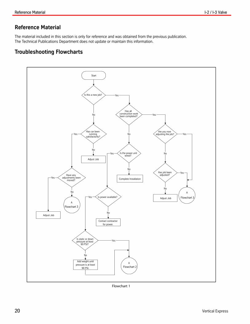
Reference Material
The material included in this section is only for reference and was obtained from the previous publication. The Technical Publications Department does not update or maintain this information.
Troubleshooting Flowcharts
Flowchart 1
Start
Is this a new job?
Has car beenrunning
satisfactorily?
Is static or downpressure at least
90 PSI?
Has job beenadjusted?
Is power available?
Is the power unitwired?
Are you nowadjusting the job?
Has allconstruction workbeen completed?
No
No
Yes
Adjust Job
Add weight untilpressure is at least
90 PSI.
A
Flowchart 3
No
No
No
Adjust Job
Complete Installation
No
Adjust Job
No
Have anyadjustments been
moved?
A
Flowchart 3
No
Contact contractorfor power.
A
Flowchart 2
YesYes
Yes
Yes
Yes
Yes
Yes
Yes
No

I-2 / I-3 Valve Troubleshooting Flowcharts
Printed in USA May, 2012 21
Flowchart 2
A
Will the car run in bothdirections?
Turn over to constructioncrew.
Adjust only thru initialadjustments.
Turn over to constructioncrew.
No
Yes

Troubleshooting Flowcharts I-2 / I-3 Valve
22 Vertical Express
Flowchart 3
A
Flowchart 18
Problem Direction
A
Does the car settle(leak) down?
No
A
Flowchart 5
Run car to lowest position.
Is the oil level in thetank less than originally
set?
Close line valve.
Does the car stillsettle?
No
Inspect Oil line and powerunit for leaks. Correct
Verify proper performance.
Does the car stillsettle?
No
Close manual loweringvalve tightly.
Run the car to the top.
Shut off the power.
Record car location.
After 15 minutes, record carlocation
Record amount car hassettled (X).
Let car sit for 8 hours andthen record car location.
Check jack for leaks.
Yes
No
Yes
Yes
Yes
Down OperationUp Operation
Flowchart 4

I-2 / I-3 Valve Troubleshooting Flowcharts
Printed in USA May, 2012 23
Flowchart 4
A
Record amount car hassettled (Y).
Is Y more than 25times X?
No
Arrange for homing tolowest floor.
Verify proper performance.
Close down start record carlocation.
After 15 minutes, record carlocation.
Record amount car hassettled (Z).
Is Z less than X?
No
Remove and examinelowering piston.
No
Is the piston seatdamaged?
No
Remove andexamine check piston.
No
Is piston seatdamaged?
Replace down pilot body.
Adjust down functions.
Reseat piston.
Verify proper performance.
Reseat piston.
Verify proper performance.
No
Replace valve.
Adjust job.
Yes
Yes
Yes
Yes

Troubleshooting Flowcharts I-2 / I-3 Valve
24 Vertical Express
Flowchart 5
A
Set up a down call
Does the car lower atall?
No
Is the line valve open?
No
Open line valve.
Does the car operateOK?
No
Does the car lower atall?
Yes
Yes
Yes
Yes
R
Does the car lower atcontract speed?
No
Does the car lower atless than contract
speed?
Adjust lowering speed.
No
Verify proper performance.
Yes
Yes
A
Flowchart 12
A
Flowchart 9
Verify proper performance.
R
Flowchart 5
Is down fastenergized?
No
Is there voltage oncoil?
No
Not a valve problem.
Yes
Replace solenoid coil.
A
Flowchart 6
No
Flowchart 7
A

I-2 / I-3 Valve Troubleshooting Flowcharts
Printed in USA May, 2012 25
Flowchart 6
A
Does the car operateOK?
No
No
Does the car lower atall?
A
Flowchart 7
Yes
Yes
Verify proper performance.
R
Flowchart 5

Troubleshooting Flowcharts I-2 / I-3 Valve
26 Vertical Express
Flowchart 7
A
Turn off power.
Close manual loweringvalve.
Record the number of turnsthat the start and stopadjustments are open.
Was start open widerthan stop?
Put stop at original setting.
No
Turn power on.
Open start wider than stop.
Does car lower?
A
Flowchart 8
Adjust to proper operation.
Are flats on levelingspeed adjustment at
45_?
No
Turn to 45_. *
Replace valve.
Adjust job.
Yes
Yes
Yes
No
* NOTERemove PressureFrom Down Valve.
I-2 / I-3 Valve Troubleshooting Flowcharts
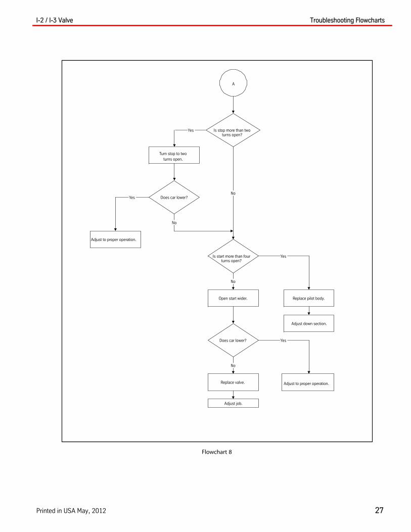
Printed in USA May, 2012 27
Flowchart 8
A
Is stop more than twoturns open?
Yes
Turn stop to twoturns open.
Does car lower?
No
No
Is start more than fourturns open?
No
Open start wider.
Replace valve.
Does car lower?
No
Adjust job.
Yes
Replace pilot body.
Adjust down section.
Yes
Adjust to proper operation.
Yes
Adjust to proper operation.

Troubleshooting Flowcharts I-2 / I-3 Valve
28 Vertical Express
Flowchart 9
Page 9
A
Does car lower atleveling speed?
No
Does car lower atless than leveling
speed?
Yes
Record the number of turnsthat the start and stopadjustments are open.
Open start wider than stop.
Was start openwider than stop?
YesOpen down start one turn.
Does the car runfaster than leveling
speed?
No
Replace solenoid.
Verify proper performance.
Yes
Yes
Is down speedadjustment handle
1/2” out of cap?
No
Set at 3/4”.
A
Flowchart 10
Yes
Replace valve.
Adjust job.
No
B
Flowchart 10
No
Is there voltage oncoil.
No
Not a valve problem.
Yes
Replace coil.
Verify proper performance.
No
Is the down fastsolenoid ener-gized?
Yes
B
Flowchart 10

I-2 / I-3 Valve Troubleshooting Flowcharts
Printed in USA May, 2012 29
Flowchart 10
BA
Does the car lower atmore than leveling
speed?
NoRun the car down on
inspection.
Replace valve.
Adjust job.
Is down stop abrupt?Yes
Turn in on down stop.
Is lowering speed OK?
No
Is down stop toosmooth?
B
Flowchart 11
No
No
Yes
Turn out on down stop anddown start.
Is lowering speed OK?
Turn out on down start.
Is lowering speed OK?
No
Adjust lowering speed.
A
Flowchart 11
Yes
Yes
Yes
B
Flowchart 11
No

Troubleshooting Flowcharts I-2 / I-3 Valve
30 Vertical Express
Flowchart 11
A B
Is lowering speed OK?
Is down start OK?
Yes
No
Adjust down start.
No
Replace valve.
Adjust job.
Yes
Does slowdown feelOK?
No
Adjust slowdown.
Does empty car have3” or 4” of leveling?
No
Move slowdown signal toget 3” to 4” of leveling.
Verify proper performance.
Yes
Yes

I-2 / I-3 Valve Troubleshooting Flowcharts
Printed in USA May, 2012 31
Flowchart 12
A
Yes Does the car reachfloor level at each
floor?
Does the car stopproperly at each floor?
Yes
No
Does the car stopproperly at any floor/
No
Does the car stopabove the floor?
No
Does the car stopbelow the floor?
No
C
D
Flowchart 13Yes Yes
No
Does the car reachfloor level at any floor?
No
Replace down sidestrainer.
Yes
No
Does the car stopproperly at each floor?
No
C
Flowchart 13
Does the car level atall?
No
Yes
B
Flowchart 13
C
Flowchart 15
A
Flowchart 13
Yes
Yes
Flowchart 13

Troubleshooting Flowcharts I-2 / I-3 Valve
32 Vertical Express
Flowchart 13
A
B
C D
Does the carstop properlyat any floor?
Not a valve problem.Set all slowdownsignals the same
distance from the floor.
Does stop feelsatisfactory?
Run the car down oninspection.
Verify properperformance.
Does the carrun at 10 to 12
FPM?
Adjust leveling speed.
Is stop toohard?
Is stop toosoft?
Is stop adouble-stop?
Is stop OK?
Turn out on stopadjustment.
Turn in on stopadjustment.
A
Flowchart 14
B
Flowchart 14
C
Flowchart 14
D
Flowchart 14
No
No
Yes
Yes
Yes
No
No
No
No
Yes
No
Yes
Yes
Yes
I-2 / I-3 Valve Troubleshooting Flowcharts
Printed in USA May, 2012 33
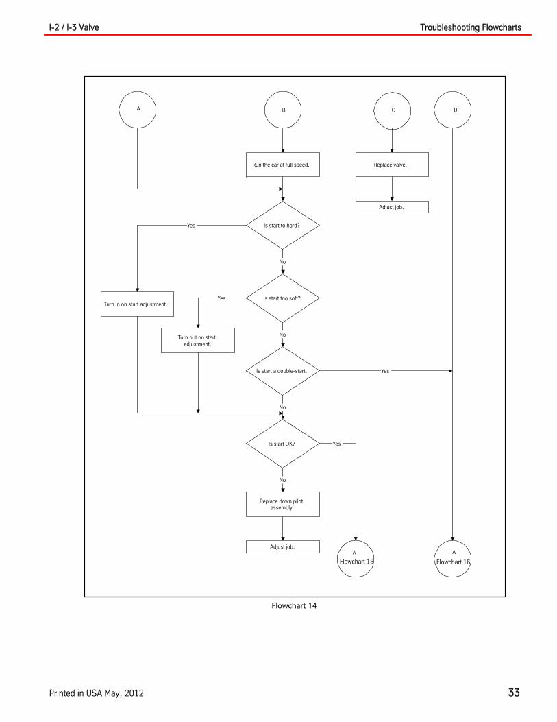
Flowchart 14
A DB C
Replace valve.
Replace down pilotassembly.
Is start to hard?
Is start too soft?
Is start a double-start.
Is start OK?
Adjust job.
Run the car at full speed.
Adjust job.
Turn out on startadjustment.
Turn in on start adjustment.
No
No
No
No
Yes
Yes
Yes
Yes
A
Flowchart 15
A
Flowchart 16

Troubleshooting Flowcharts I-2 / I-3 Valve
34 Vertical Express
Flowchart 15
CA
Is slowdown too hard? Is down slow solenoidenergized?
Is slowdown too soft? Is there voltage on thecoil?
Is slowdown OK?
Turn in on slowdownadjustment.
Turn out on slowdownadjustment?
Open manual loweringvalve.
Does car lower?
Is voltage OK?
Not a valve problem.
Replace solenoid.
Close manual loweringvalve.
Verify properperformance.
Replace down pilotassembly.
Adjust job.
Does car have 2” to 3”of leveling at each
floor?
Adjust location ofslowdown signal.
Verify properperformance.
A
Flowchart 7
No No
No Not a valve problem.
NoReplace coil.
Verify properperformance.
YesYes
No
Yes
No
No
Yes
Yes
YesYes
No
Yes

I-2 / I-3 Valve Troubleshooting Flowcharts
Printed in USA May, 2012 35
Flowchart 16
A
Install pressure gaugeat bleed plug at jack.
Record pressure asempty car runs up and
down past a givenpoint.
Is difference inpressure more than
25 PSI?
Remove and examinelowering piston.
Is distance from seatto bottom of slotsmore than 1/8”?
Replace valve.
Adjust job.
Replace loweringpiston.
Verify properperformance.
Run car from bottom totop. Record pressure
every 3’ 0” as car runsup.
Did pressureincrease and then
drop back at any onespot?
Run car down. Recordpressure every 3” 0” as
car runs down.
Did pressuredecrease and then
climb at any onespot?
Jack is probably dog-legged at that point.
B
Flowchart 17A
Flowchart 17
No
Yes
Yes Yes
Yes
No
No
No

Troubleshooting Flowcharts I-2 / I-3 Valve
36 Vertical Express
Flowchart 17
A B
Does pressure at topand at bottom differmore than 20 PSI?
Jack and rails are probablynot aligned with each other.
Verify and replumb jack and/or realign jack and rails.
No
Yes

I-2 / I-3 Valve Troubleshooting Flowcharts
Printed in USA May, 2012 37
Flowchart 18
A
Register an Up call.
Does the car run UpOK at high speed?
A
Flowchart 19
Does the car level UpOK?
Is Up slow solenoidenergized?
Is there voltage on thecoil?
Not a valve problem.
Verify proper performance.
Replace coil.
Put car on inspection.
Is Up inspection speed8 to 20 FPM?
A
Flowchart 26
Reconnect Up slowsolenoid.
Place car on automatic.
A
Flowchart 30
Does car stand still?
Disconnect Up slowsolenoid.
B
Flowchart 19
Run car Up on inspection.
A
Flowchart 26
No
No
Yes
No
No
Yes
Yes
Yes
No
Yes
Yes
No

Troubleshooting Flowcharts I-2 / I-3 Valve
38 Vertical Express
Flowchart 19
A B
Is motor running?
Does car move at all?
Verify proper performance.
Is the pump turning?
A
Flowchart 23
Does car stand still?
Not a valve problem?
Correct drive.
Is there voltage on thecoil?
Is Up fast solenoidenergized?
Not a valve problem.
Replace coil.
Verify proper performance.
Set stop at two turns open.
Is stop more than oneturn open?
B
Flowchart 23
Reconnect Up slowsolenoid.
Adjust unit.
Turn off power.
Verify proper performance.
Record the number of turnsstart and stop adjustment
are opened.
A
Flowchart 20
No
No
Yes
Yes
No
Yes
No
No
Yes
Yes
No
No
Yes
Yes
No

I-2 / I-3 Valve Troubleshooting Flowcharts
Printed in USA May, 2012 39
Flowchart 20
A
Was start open widerthan stop?
Replace valve.
Set stop at original settings.
Open start 3 turns widerthan stop.
Adjust job.
Does car run Up?
Replace Up sidestrainer.
Adjust valve.
Does car run Up?
Adjust valve.
Is stop more than twoturns open?
B
Flowchart 21
Set stop at two turns.
A
Flowchart 21
No
No
No
No
Yes
Yes
Yes
Yes

Troubleshooting Flowcharts I-2 / I-3 Valve
40 Vertical Express
Flowchart 21
A B
Does car run Up?
Adjust valve.
Is start more than fourturns open?
Open start to more than fourturns.
Does car run Up?
Does relief adjustmenthave less than 5/8” out
side main nut?
Turn in on relief adjustmentuntil less than 5/8” sticks out
from main nut.
Adjust valve.
B
Flowchart 22
A
Flowchart 22
Yes
No
Yes
No
No
No
Yes
Yes

I-2 / I-3 Valve Troubleshooting Flowcharts
Printed in USA May, 2012 41
Flowchart 22
BA
Does car run Up?
Does pilot piston movefreely?
Examine piston and spring.
Is spring broken?
Replace piston.
Does car run Up?
Replace valve.
Adjust job.
Adjust valve.
Is spring broken?
Replace spring.
Adjust valve.
No
No
No
No
Yes
Yes
Yes
Yes
No
Yes

Troubleshooting Flowcharts I-2 / I-3 Valve
42 Vertical Express
Flowchart 23
A
Is Up slowenergized?
Open Up start two fullturns.
Is Up fastenergized?
Should Up slow beenergized?
Not a valve problem.
Back off on lowpressure while pump is
running.
Does car run at fullspeed?
Adjust valve.
Is stop more thantwo turns open?
Close stop to two turnsopen.
Will car stand still?
Open Up stop until carstands still or to a max.
of 6 turns.
Will car stand still?
Reconnect Up slowsolenoid.
Adjust valve.
Adjust low pressure.
Does car standstill?
Reconnect Up slowsolenoid.
Adjust valve.
A
Flowchart 26
C
Flowchart 24
A
Flowchart 22
A
Flowchart 24
B
Flowchart 24
B
Yes
No
No
Yes
Yes
No
No
No
No
Yes
Yes
No
Yes
Yes
No
Yes

I-2 / I-3 Valve Troubleshooting Flowcharts
Printed in USA May, 2012 43
Flowchart 24
CBA
Does car run at fullspeed?
Close start.
Does car standstill?
Replace valve.
Adjust valve.
Does relief haveless than 5/8”
outside main nut?
Turn in on relief.
Does car runfaster?
Does pilot pistonmove freely?
Adjust valve.
Does car operateOK?
Adjust job.
Adjust valve.
B
Flowchart 25
A
Flowchart 25
Yes
No
No
Yes
No
Yes
Yes
No
No
Yes
No
No
Replace up fastsolenoid.
Yes
Troubleshooting Flowcharts I-2 / I-3 Valve
44 Vertical Express
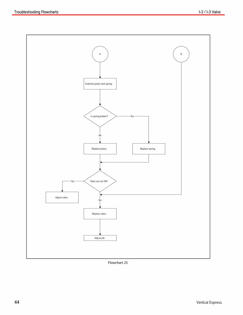
Flowchart 25
A B
Replace piston.
Is spring broken?
Adjust valve.
Adjust job.
Examine piston and spring.
Does car run OK?
Replace valve.
Replace spring.
No
Yes
Yes
No

I-2 / I-3 Valve Troubleshooting Flowcharts
Printed in USA May, 2012 45
Flowchart 26
A
Put car on inspection.
Does the car run fasterthan leveling speed?
Does car run atleveling speed?
Set slowdown two turnsopen.
Is slowdown more thanthree turns open?
Is up leveling speedadjusted in less than
four turns?
A
Flowchart 27
Adjust valve.
Is up fast energized?
Close up start adjustment.
Does the car run fasterthan leveling speed?
Set at four turns in.
Replace up fast solenoid.
Verify proper performance.
Replace valve.
Adjust job.
Not a valve problem.
No
No
Yes
Yes Yes
No
Yes
No
No
Yes
No
Yes
B
Flowchart 27
Troubleshooting Flowcharts I-2 / I-3 Valve
46 Vertical Express
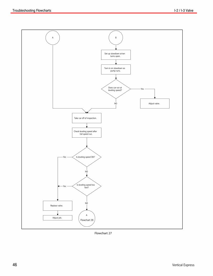
Flowchart 27
BA
Set up slowdown at tenturns open.
Turn in on slowdown aspump runs.
Does car run atleveling speed?
Replace valve.
Take car off of inspection.
Check leveling speed afterfull speed run.
Is leveling speed OK?
Is leveling speed toofast?
AAdjust job.
Adjust valve.NO
NO
NO
Yes
Yes
Yes
Flowchart 28

I-2 / I-3 Valve Troubleshooting Flowcharts
Printed in USA May, 2012 47
Flowchart 28
A
Does relief adjustment
have less than 5/8”
outside main nut?
Turn in on relief until lessthan 5/8” sticks out main
nut.
Turn in on slowdownadjustment as pump runs.
Open slowdown to ten turnsopen.
Does car run atleveling speed?
Is relief spring broken?
check strainer on up levelingspeed adjustment.
A
Adjust valve.
Replace spring.
Yes
No
No
No
Yes
Yes
Adjust valve.
Flowchart 29
Troubleshooting Flowcharts I-2 / I-3 Valve
48 Vertical Express
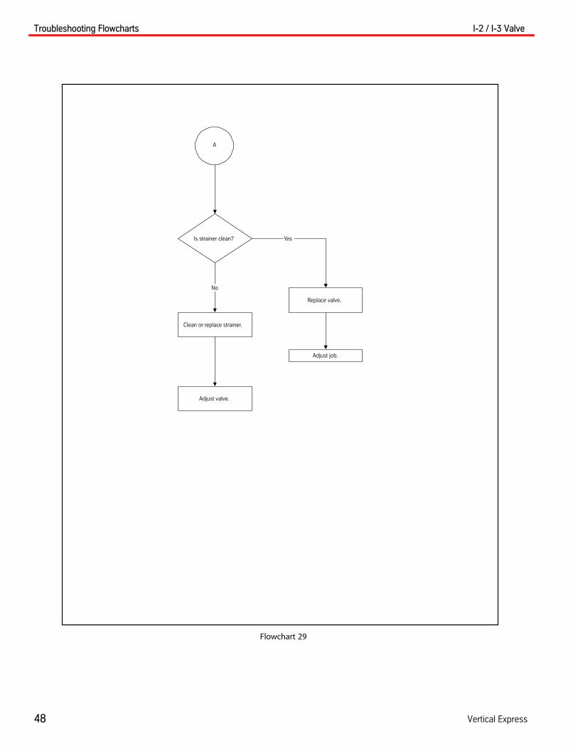
Flowchart 29
A
Is strainer clean?
Replace valve.
Adjust job.
Clean or replace strainer.
Adjust valve.
No
Yes

I-2 / I-3 Valve Troubleshooting Flowcharts
Printed in USA May, 2012 49
Flowchart 30
A
Does stop feel OK?
Does car stopproperly at any
floor?
Does car level at10 to 12 FPM?
Does car havemore than 3” to 4”
of leveling?
Not a valve problem.Set all slowdownsignals the same
distance from the floor.
Take car off inspection.
Adjust stop.
Does car stopproperly at each
floor?
Does start feelOK?
Is leveling speedless than 10 FPM?
Set all slowdownsignals so car has 3” to
4” of leveling.
Does slowdownfeel OK?
Is leveling speedadjustment strainer
clean?
Adjust slowdown. Clean strainer.
Verify properperformance.
Verify properperformance.
Run car on inspection.
A
CBA
No
No
No
No
Yes
Yes
Yes
Yes
No
Yes
Yes
No
Yes
No
Yes
No
No
Yes
Flowchart 31 Flowchart 32
Flowchart 32
Flowchart 32

Troubleshooting Flowcharts I-2 / I-3 Valve
50 Vertical Express
Flowchart 31
A
Does stop feel OK?
Adjust stop.
Does stop feel OK?
Verify proper performance.
No
No
Yes
Yes
Flowchart 22
A

I-2 / I-3 Valve Troubleshooting Flowcharts
Printed in USA May, 2012 51
Flowchart 32
CBA
Is start too slow?
Is start slower withfive people on car?
Is up side strainerOK?
Is relief spring OK?
Is leveling speedOK?
Adjust leveling speed.
Was slowdown orleveling speed
adjustment movedmore than one
turn?
Replace spring.
Set relief pressure.
Verify properperformance.
Is start OK?
Clean strainer.
Verify properperformance.
Adjust start.
Yes
Yes
YesNo
No
No
No
Yes
Yes
No
Verify properperformance.
No
No
Yes
A
Flowchart 26

Sequence of Events I-2 / I-3 Valve
52 Vertical Express
Sequence of Events
Up Valve Section The up valve section consists of an up leveling speed adjustment, a check valve piston, a regulator piston, and a relief valve.
The valve provides these functions for the car in the Up cycle:
• Acceleration to full speed
• Slowdown to leveling speed
• Hydraulic stopping
• High-pressure relief
Sequence of Events
1. To start the car, the pump starts and the up fast solenoid energizes. See Figure 6 on page 52 and Figure 7 on page 53.
2. The regulator piston is held open by its spring and also the pump pressure on the face of the piston against the low pressure adjustment. At the beginning, all of the oil will bypass to the tank past the regulator piston, through the up start adjustment, and to the up stop adjustment.
3. The up start adjustment is open more than the up stop adjustment, making pressure build behind the regulator piston and causes it to move toward the closed position. The open amount of the up start adjustment governs how fast the regulator piston moves and how rap-idly the car starts.
4. As the regulator piston closes, pressure from the pump builds up in the valve and causes the check valve piston to open. This action allows oil to flow from the pump into the jack.
Figure 6 - Up Start Diagram
TANK MAIN FLOW
CONTROL FLOW
Relief Pressure Adjustment Screw
High-PressureRelief Pilot
Up Slow Solenoid(Closed)
Up SlowdownAdjustment
Pressure ControlPiston
Up StopAdjustment
Up Pilot Piston
Up Fast Solenoid(Open)
Up Start Adjustment
Up Leveling Speed AdjustmentCheck ValvePiston
PUMP JACK
RegulatorPiston
LowPressureAdjustment

I-2 / I-3 Valve Sequence of Events
Printed in USA May, 2012 53
Up Valve Section(continued)
Figure 7 - Full Speed Diagram
TANK
MAIN FLOW
CONTROL FLOW
Relief Pressure Adjustment Screw
High-PressureRelief Pilot
Up Slow Solenoid(Closed)
Up SlowdownAdjustment
Pressure ControlPiston
Up StopAdjustment
Up Pilot Piston
Up Fast Solenoid(Open)
Up Start Adjustment
Up Leveling Speed AdjustmentCheck ValvePiston
PUMP JACK
RegulatorPiston
LowPressureAdjustment

Sequence of Events I-2 / I-3 Valve
54 Vertical Express
High-pressure Relief Sequence of Events
1. The oil is transmitted to the high-pressure pilot. See Figure 8.
2. The movement allows the oil in back of the regulator piston and at the high-pressure adjustment to escape to the tank.
3. The regulator piston moves rapidly to the low-pressure stud, allows full bypass from the pump to the tank, and relieves the excess pressure.
4. The system only maintains relief pressure as long as the pump continues to run.
Figure 8 - High-Pressure Relief Diagram
TANK MAIN FLOW
CONTROL FLOW
Relief Pressure Adjustment Screw
High-PressureRelief Pilot
Up Slow Solenoid(Closed)
Up SlowdownAdjustment
Pressure ControlPiston
Up StopAdjustment
Up Pilot Piston
Up Fast Solenoid(Open)
Up Start Adjustment
Up Leveling Speed Adjustment Check ValvePiston
PUMP JACK
RegulatorPiston
LowPressure Ad-justment

I-2 / I-3 Valve Sequence of Events
Printed in USA May, 2012 55
Up Slowdown and Leveling Speed
Sequence of Events
1. From slowdown to leveling speed, the up fast solenoid is de-energized and the up slow solenoid is energized. See Figure 9.
2. The pressure on the spring end of the up pilot piston is reduced, and the up pilot piston shifts to the up position.
3. The opening to the up stop adjustment is closed and the opening to the up slowdown and leveling adjuster is opened to the back of the regulator piston.
4. Pressure behind the regulator piston is reduced as the oil flows out through the up slow-down adjustment. The regulator piston starts to open.
5. The opening at the up slowdown adjustment determines the rate of oil flow from the low pressure adjustment end of the regulator piston back into tank which controls the rate of speed change. The wider the opening, the quicker the slowdown.
6. Valve pressure drops as the regulator piston opens. This action causes the check valve piston to begin to close.
7. When the slot on the check valve piston reaches the hole in the leveling speed adjustor, less oil flows from behind the regulator piston.
8. When the slot has opened enough to allow the same amount of oil to flow in the leveling speed adjustor as the amount which flows out through the up slowdown adjustment, the system reaches a hydraulic balance, known as leveling speed.
9. The leveling speed is changed by moving the hole in the leveling speed adjustor.
Figure 9 - Up Slowdown and Leveling Speed Diagram
TANK MAIN FLOW
CONTROL FLOW
Relief Pressure Adjustment Screw
High-pressureRelief Pilot
Up Slow Solenoid(Open)
Up SlowdownAdjustment
Pressure ControlPiston
Up StopAdjustment
Up Pilot Piston
Up Fast Solenoid(Closed)
Up Start Adjustment
Up Leveling Speed AdjustmentCheck ValvePiston
PUMP JACK
RegulatorPiston
LowPressure Ad-justment

Sequence of Events I-2 / I-3 Valve
56 Vertical Express
Up Stop Sequence of Events
1. The up slow solenoid is de-energized, to stop the car. The pump is kept running slightly longer on a timed delay to provide a valve stop instead of a pump stop. See Figure 10.
2. With pressure equalized on both ends of the up pilot piston, the spring will park the piston in the down position. In this position, the openings of the up slowdown and leveling adjuster will be closed and the opening of the up stop adjustment will be open.
3. The up stop adjustment allows flow out from behind the regulator piston and causes the pres-sure to drop.
4. Decreased oil pressure on the back of the regulator piston allows pressure from the jack (with the spring force) to push the piston against the low pressure adjustment stud allowing full bypass. At the same time, the check valve piston closes.
5. Stop rate is controlled by the opening at the stop adjustment. The wider the opening, the faster the stop.
Figure 10 - Up Stop Diagram
TANKCONTROL FLOW
Relief Pressure Adjustment Screw
High-pressureRelief Pilot
Up Slow Solenoid(Closed)
Up SlowdownAdjustment
Pressure ControlPiston
Up StopAdjustment
Up Pilot Piston
Up Fast Solenoid(Closed)
Up Start Adjustment
Up Leveling Speed AdjustmentCheck ValvePiston
PUMP JACK
RegulatorPiston
LowPressureAdjustment

I-2 / I-3 Valve Sequence of Events
Printed in USA May, 2012 57
Down Valve Section The down portion of the valve consists of a piston that seats and can be controlled in these positions:
• Closed to stop the car
• Partially open for slow speed
• Fully open for high speed
Down Start and Full Speed Sequence of Events
1. To start the car down, the down fast and down slow solenoids are energized simultaneously, allowing the oil behind the piston to flow to the tank through the down start adjustment. See Figure 11.
2. The reduction in pressure behind the piston causes the piston to lift. It is essential that the down start adjustment be open more than the down stop adjustment so that the oil entering through the down stop adjustment can be drained to the tank.
3. The size of the openings will govern how fast the piston moves and how rapidly the car starts. The lowering speed adjustment limits the amount the piston can open, thereby controlling the car down speed.
Figure 11 - Down Start and Full Speed Diagram
TANK
PUMP JACK
Lowering Piston Down SlowSolenoid (Open)
Down StartAdjustment
Manual Lowering
Down SlowdownAdjustment
Down FastSolenoid(Open)
Lowering Speed Adjustment
Down Stop Adjustment
Check ValvePiston
CONTROL FLOW
MAIN FLOW

Sequence of Events I-2 / I-3 Valve
58 Vertical Express
Down Slowdown and Leveling Sequence of Events
1. To change to leveling speed, the down fast solenoid is closed. The lowering piston starts in the full open position and the oil passage to the tank is blocked by the piston skirt. See Figure 12.
2. Oil flows in through the down stop adjustment to the rear of the lowering piston, and out through the slowdown adjustment. The down slow solenoid and the down start adjustment, causes the lowering piston to move toward the closed position. The amount that the down slowdown adjustment is closed governs how fast the piston moves and how rapidly the car slows down.
3. The piston will stop once the oil passage to the tank (through the down slow solenoid) is opened by the skirt of the piston.
4. The lowering speed is controlled by turning the lowering and leveling adjustment in increments of full half-turns. The leveling speed is controlled by turning the lowering and leveling adjust-ment in less than one-quarter-turn increments.
Figure 12 - Down Slowdown and Leveling Diagram
TANK
PUMP JACK
Lowering PistonDown Slow Solenoid (Open)
Down StartAdjustment
Manual Lowering
Down SlowdownAdjustment
Down FastSolenoid(Closed)
Lowering Speed Adjustment
Down Stop Adjustment
Check Valve Piston
CONTROL FLOW
MAIN FLOW
Piston Skirt

I-2 / I-3 Valve Sequence of Events
Printed in USA May, 2012 59
Manual Lowering The manual lowering valve is parallel to the down slow solenoid and when opened, allows the car to be lowered at leveling speed during emergencies.
Down Stop 1. To stop the car, the down slow solenoid is de-energized, stopping all flow to the tank. Pressure from the jack and the spring will cause the piston to close. See Figure 13.
2. The rate of closing and the smoothness is controlled by the down stop adjustment.
Figure 13 - Down Stop Diagram
TANK
PUMP JACK
Lowering Piston Down Slow Solenoid (Open)
Down StartAdjustment
Manual Lowering
Down SlowdownAdjustment
Down FastSolenoid(Open)
Lowering Speed Adjustment
Down Stop Adjustment
Check Valve Piston
CONTROL FLOW
MAIN FLOW

I-2 / I-3 Valve
60 Vertical Express
This page
intentionally
left blank.