Embed Size (px)
Citation preview
Split system Air Conditioning 50 Hz / R22
HyperionTM Split Systems
SSA-PRC010-E4
© 2013 Trane 2 SSA-PRC010-E4
Features and Benefits
Outdoor unit 2TTB• Climatuff®compressor•AllaluminumSpine Fin™coil•DuraTuff™base,fastcompletedrain,
weatherproof•Newcabinetwithanthracitebaseand
polystategraycabinet•Quick-Sess™cabinet,serviceaccess
andrefrigerantconnectionswithfullcoilprotection
•Corrosionresistantfinishandfasteners•High/lowpressureandtemperature
protection•Liquidlinefilter-drier•Easysinglesideservice•Multi-useliquidandsuctionlineservice
valves•Easytopandfanremoval•Fulllengthcontrolcover•Sure Fast™seamslouverpanelremoval•HCFC-22refrigerant•Extendedwarrantiesavailable•S.E.E.T.designtesting•100%lineruntest
Outdoor unit 2TTA•Climatuff®compressor•AllaluminumSpine Fin™coil•DuraTuff™base,fastcompletedrain,
weatherproof•WeatherGuard™fasteners•Quick-Sess™cabinet,serviceaccess
andrefrigerantconnectionswithfullcoilprotection
•Corrosionresistantfinishandfasteners•High/lowpressure&temperature
protection•Liquidlinefilter-drier•Comfort “R”™modeapproved•Easysinglesideservice•Multi-useliquidandsuctionline
servicevalves•Compressorsumpheat•Easytop&fanremoval•HCFC-22refrigerant•S.E.E.T.designtesting•100%lineruntest
Indoor convertible air handler GAF• UniqueCabinetDesign-DoubleWallFoamedandFormed
CabinetSystem-WaterProofCabinetDesign-R-4.2InsulatingValue(Avg.Insulating
ValueR-8)-CompositeFoamedCabinetDoors-SweatEliminatingCabinetDesign-LooseFiberEliminatingCabinet
Design-SmoothCleanableCabinetDesign-2%orLessairleakage-PrecisionAppliedDurableDoorSeals• Multi-PositionUpflow/Horizontal
Left/HorizontalRight• FrontReturnOption• BrazeinRefrigerantConnection• Primary/SecondaryCondensate
Connections• VorticaBlowerwithIntegratedSlide
DeckforEasyRemoval• PolarizedPlugconnectionson
Blower• AluminumCoilwithIntegratedSlide
DeckforEasyRemoval• SlideinElectricHeaters• PolarizedPlugconnectionsfor
ElectricHeater• LabeledPanelsandconnections• Guidefor1-1/4"to1"And3/4"to1/2"
ConduitconnectiononTop• R-410AThermalExpansionValve
(TXV)• ConvertibletoR-22usingoptional
accessoryTXVconversionkit• LowVoltageColorCodedWires• EnhancedCoilFinPatented• BlowThroughDesign• PSC3SpeedMotor• MaximumWidthof17.5"• Compact20.8"depthwithdoors
removed• IntegratedHorizontalDrainpans• SingleColor• Fused24VPower
Indoor convertible air handler GAT/GAM• UniqueCabinetDesign-DoubleWallFoamedandFormed
CabinetSystem-WaterProofCabinetDesign
-R-4.2InsulatingValue(Avg.InsulatingValueR-8.2)
-CompositeFoamedCabinetDoors-SweatEliminatingCabinetDesign-LooseFiberEliminatingCabinet
Design-SmoothCleanableCabinetDesign-2%orLessairleakage-PrecisionAppliedDurableDoorSeals-Tool-freeFastenersonBlower/Filter
Door-ModularCabinet• Multi-PositionUpflow/Horizontal
Left/HorizontalRight• BrazeinRefrigerantConnection• Primary/SecondaryCondensate
Connections• PremarkedConduitConnection
Locations• VorticaBlowerwithIntegrated
SlideDeckforEasyRemoval• PolarizedPlugconnectionson
Blower• ControlProtectionPocket• AluminumCoilwithIntegratedSlide
DeckforEasyRemoval• SlideinElectricHeaters• PolarizedPlugconnectionsfor
ElectricHeater• LabeledPanelsandconnections• 1-1/4"to1"and3/4"to1/2"Conduit
connectiononLeft,RightandTop• Moldedin1"StandardFilterrail• R-410AThermalExpansionValve
(TXV)• ConvertibletoR-22usingoptional
accessoryTXVconversionkit• LowVoltageTerminalConnection
Point• EnhancedCoilFinPatented• BlowThroughDesign• PSC3SpeedMotoron3.5&4ton
models• ConstanttorqueECMMotoron5ton
model• MaximumWidthof23.5"• Compact20.8"depthwithdoors
removed• IntegratedHorizontalDrainpans• SingleColor• Fused24VPower• SafetyDoorSwitch
SSA-PRC010-E4 3
Contents
Features and Benefits 2Nomenclature 4 Unique Cabinet Design Features and Benefits GAF 5Unique Cabinet Design Features and Benefits GAT/GAM 6General Data 2TTA 7General Data 2TTB 8General Data GAF/GAT/GAM 9Airflow Data GAF 10Airflow Data GAT/GAM 11Performance Data 13Electrical Data GAF 35Electrical Data GAT/GAM 36Wiring 2TTB 38Wiring 2TTA 40Field wiring GAF/GAT/GAM 43Convertibility GAF/GAT/GAM 45Dimensions 2TTB 46Dimensions 2TTA 47Dimensions GAF 48Dimensions GAT/GAM 50Mechanical Specifications 52

4 SSA-PRC010-E4
G A F 2 A 0 B 3 6 M 3 1 S A A
BrandT = BetterG = Good
Product TypeA = Air Handler
Product Tier2 = Good, Entry Level Feature Set4 = Better, Retail Replacement Mid Effy.5 = Better, Entry Level High Effy., Multi-Speed7 = Best, Retail Replacement High Effy., Variable-Speed8 = Best, Retail Ultimate High Effy., Variable-Speed
Major Design Change
Minor Design ChangeUnit Parts Identifier
Airflow Type & CapabilityS = Low Effy PSC, 1-5 - nom. Tonnage (cfm/ton)M = Mid Effy Multi-Speed, 1-5 - nom. Tonnage (cfm/ton)H = High Effy Multi-Speed, 1-5 - nom. Tonnage (cfm/ton)V = High Effy Variable, 1-5 - nom. Tonnage (cfm/ton)
No Descriptor0 = Air Handler / Coil
System Control TypeS = Standard - 24 VACC = CLII 13.8 VDC
Size (Footprint)A = 17.5 x 21.5B = 21.0 x 21.5C = 23.5 x 21.5
Cooling Size: Air Handler or Coil0-9 = AH Coil - 1000 BTU’s (36, 48, 60)
Power Supply220 - 240/1/50
ConvertabilityM = Multi-poise 4-wayF = Upflow Front Return, 3-wayT = 3-way
Air Handler
Refrigerant Type2 = R-224 = R-410A
TRANE
Product TypeW = Split Heat PumpT = Split Cooling
Product FamilyZ = Leadership – Two StageX = LeadershipR = Replacement/RetailB = BasicA = Light Commercial
Family SEER0 = 10 3 = 13 6 = 161 = 11 4 = 14 8 = 182 = 12 5 = 15 9 = 19
Split System Connections 1-6 Tons0 = Brazed
Nominal Capacity in 000s of BTUs
Major Design Modifications
Power Supply
Secondary Function
Minor Design Modifications
Unit Parts Identifier
Outdoor Units4 T T B 3 0 3 6 A A 0 0 0 A A
Refrigerant Type2 = R-224 = R-410A
TRANE
Product TypeW = Split Heat PumpT = Split Cooling
Product FamilyZ = Leadership – Two StageX = LeadershipR = Replacement/RetailB = BasicA = Light Commercial
Family SEER0 = 10 3 = 13 6 = 161 = 11 4 = 14 8 = 182 = 12 5 = 15 9 = 19
Split System Connections 1-6 Tons0 = Brazed
Nominal Capacity in 000s of BTUs
Major Design Modifications
Power SupplyA = 220-240/1/50 H D = 380-415/3/50
Secondary Function
Minor Design Modifications
Unit Parts Identifier
Outdoor Units4 T T A 3 0 3 6 A D 0 0 0 A A
A = 220-240/1/50 H D = 380-415/3/50
Nomenclature
5
A

SSA-PRC010-E4 5
Unique Cabinet Design Features and Benefits GAF
5 Conduit Connection Location
r Integrated Horizontal Drain Pans
e Compact 20.8” Depth with Doors Removed
1 Unique Cabinet Design
2 Precision Durable Door Seals
q Thermal Expansion Valve (TXV)
3 Refrigeration Connections
9 All Aluminum Coil
4 Condensate Connections
w Maximum width is 17.5”
8 VorticaTM Blower and Deck
0 Labeled Panels and Connections
1 Unique Cabinet Design - Double wall foamed cabinet system - Waterproof Cabinet Design - R-4.2 Insulating Value (Avg. Insulating Value R-8) - Composite Foamed Cabinet Doors - Sweat Eliminating Cabinet Design - Loose Fiber Eliminating Design - Smooth Cleanable Cabinet Design - 2% or Less air leakage2 Precision Durable Door Seals3 Brazed Refrigeration Connections4 Primary/Secondary Condensate Connections5 Conduit Connection - Conduit Connection on Top7 PSC 3 Speed Motor8 VorticaTM Blower and Deck - Polarized Plug on Blower
9 All Aluminum Coil - Integrated Slide Deck for Easy Removal - Polarized Plug connections on Coil TXV - Patented Enhanced Coil Fin0 Labeled Panels and Connectionsq R-410A Thermal Expansion Valve (TXV)w Maximum width is 17.5”e Compact 20.8” Depth with Doors Removedr Integrated Horizontal Drain Pans
7 PSC 3 Speed Motor

6 SSA-PRC010-E4
Unique Cabinet Design Features & Benefits GAT/GAM
5 Conduit Connections
e Integrated Horizontal Drain Pans
6 Tool-less Door Fasteners
w Compact 20.8” Depth with Doors Removed
1 Unique Cabinet Design2 Precision Durable
Door Seals
0 Thermal Expansion Valve (TXV)
3 Refrigeration Connections
8 All Aluminum Coil
r Safety Door Switch
4 Condensate Connections
q Maximum width is 23.5”
7 VorticaTM Blower and Deck
9 Labeled Panels and Connections
1 Unique Cabinet Design - Double wall foamed cabinet system - Waterproof Cabinet Design - R-4.2 Insulating Value (Avg Insulating Value R-8.2) - Composite Foamed Cabinet Doors - Sweat Eliminating Cabinet Design - Loose Fiber Eliminating Design - Smooth Cleanable Cabinet Design2 Precision Durable Door Seals3 Refrigeration Connections4 Condensate Connections5 Premarked Conduit Connection Locations
- Conduit Connections on Left, Right, and Top6 Tool-less Door Fasteners7 VorticaTM Blower and Deck - Polarized Plug on Blower 8 All Aluminum Coil
- Integrated Slide Deck for Easy Removal - Polarized Plug connections on Coil EEV - Patented Enhanced Coil Fin9 Labeled Panels and Connections0 R-410A Thermal Expansion Valve (TXV)q Maximum width is 23.5”w Compact 20.8” Depth with Doors Removede Integrated Horizontal Drain Pansr Safety Door Switch - Fused 24V Powert Modular Cabinet
SSA-PRC010-E4 7
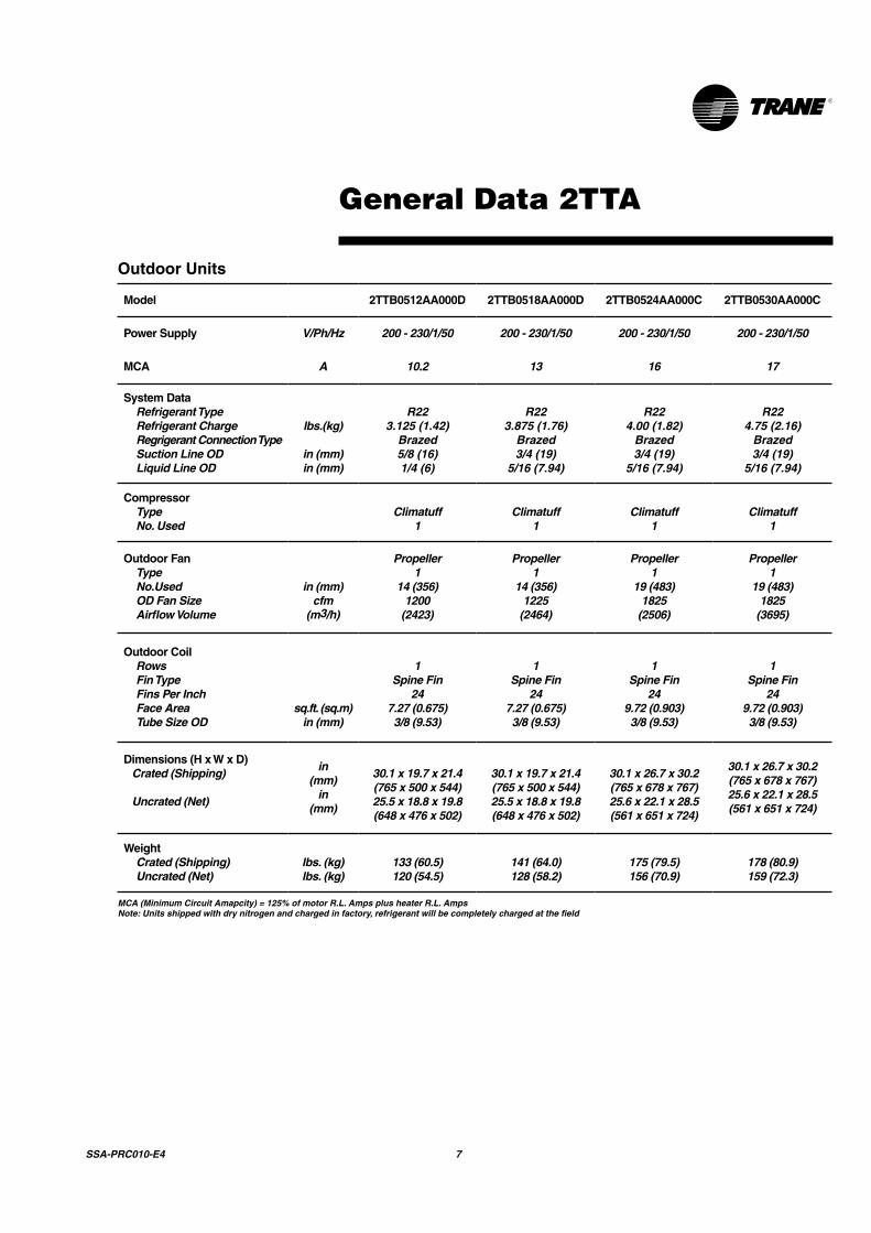
General Data 2TTA
Model 2TTB0512AA000D 2TTB0518AA000D 2TTB0524AA000C 2TTB0530AA000C
Power Supply V/Ph/Hz 200 - 230/1/50 200 - 230/1/50 200 - 230/1/50 200 - 230/1/50
MCA A 10.2 13 16 17
System DataRefrigerant TypeRefrigerant ChargeRegrigerant Connection TypeSuction Line ODLiquid Line OD
lbs.(kg)
in (mm)in (mm)
R223.125 (1.42)
Brazed5/8 (16)1/4 (6)
R223.875 (1.76)
Brazed3/4 (19)
5/16 (7.94)
R224.00 (1.82)
Brazed3/4 (19)
5/16 (7.94)
R224.75 (2.16)
Brazed3/4 (19)
5/16 (7.94)
CompressorTypeNo. Used
Climatuff1
Climatuff1
Climatuff1
Climatuff1
Outdoor FanTypeNo.UsedOD Fan SizeAirflow Volume
in (mm)cfm
(m3/h)
Propeller1
14 (356)1200
(2423)
Propeller1
14 (356)1225
(2464)
Propeller1
19 (483)1825
(2506)
Propeller1
19 (483)1825
(3695)
Outdoor CoilRowsFin TypeFins Per InchFace AreaTube Size OD
sq.ft. (sq.m)in (mm)
1Spine Fin
247.27 (0.675)3/8 (9.53)
1Spine Fin
247.27 (0.675)3/8 (9.53)
1Spine Fin
249.72 (0.903)3/8 (9.53)
1Spine Fin
249.72 (0.903)3/8 (9.53)
Dimensions (H x W x D)Crated (Shipping)
Uncrated (Net)
in(mm)
in(mm)
30.1 x 19.7 x 21.4(765 x 500 x 544)25.5 x 18.8 x 19.8(648 x 476 x 502)
30.1 x 19.7 x 21.4(765 x 500 x 544)25.5 x 18.8 x 19.8(648 x 476 x 502)
30.1 x 26.7 x 30.2(765 x 678 x 767)25.6 x 22.1 x 28.5(561 x 651 x 724)
30.1 x 26.7 x 30.2(765 x 678 x 767)25.6 x 22.1 x 28.5(561 x 651 x 724)
WeightCrated (Shipping)Uncrated (Net)
lbs. (kg)lbs. (kg)
133 (60.5)120 (54.5)
141 (64.0)128 (58.2)
175 (79.5)156 (70.9)
178 (80.9)159 (72.3)
Outdoor Units
MCA (Minimum Circuit Amapcity) = 125% of motor R.L. Amps plus heater R.L. Amps Note: Units shipped with dry nitrogen and charged in factory, refrigerant will be completely charged at the field
8 SSA-PRC010-E4
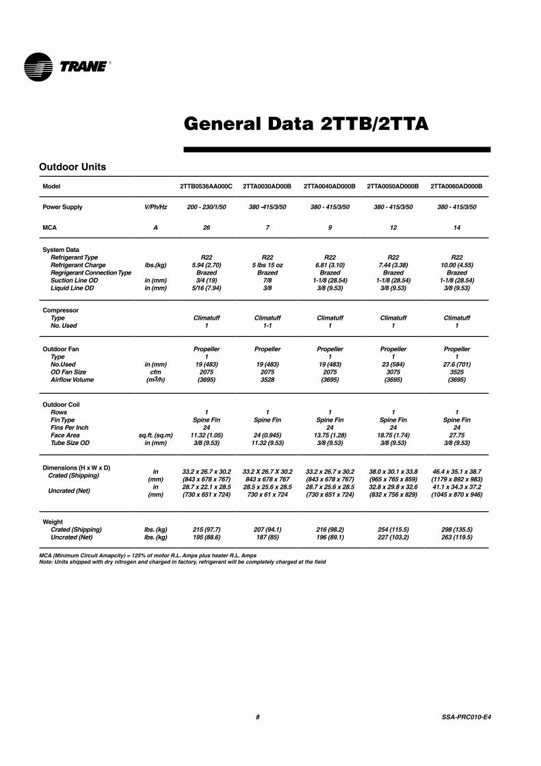
General Data 2TTB/2TTA
Outdoor Units
Model 2TTB0536AA000C 2TTA0030AD00B 2TTA0040AD000B 2TTA0050AD000B 2TTA0060AD000B
Power Supply V/Ph/Hz 200 - 230/1/50 380 -415/3/50 380 - 415/3/50 380 - 415/3/50 380 - 415/3/50
MCA A 26 7 9 12 14
System DataRefrigerant TypeRefrigerant ChargeRegrigerant Connection TypeSuction Line ODLiquid Line OD
lbs.(kg)
in (mm)in (mm)
R225.94 (2.70)
Brazed3/4 (19)
5/16 (7.94)
R225 lbs 15 oz
Brazed7/83/8
R226.81 (3.10)
Brazed1-1/8 (28.54)
3/8 (9.53)
R227.44 (3.38)
Brazed1-1/8 (28.54)
3/8 (9.53)
R2210.00 (4.55)
Brazed1-1/8 (28.54)
3/8 (9.53)
CompressorTypeNo. Used
Climatuff1
Climatuff1-1
Climatuff1
Climatuff1
Climatuff1
Outdoor FanTypeNo.UsedOD Fan SizeAirflow Volume
in (mm)cfm
(m3/h)
Propeller1
19 (483)2075
(3695)
Propeller
19 (483)20753528
Propeller1
19 (483)2075
(3695)
Propeller1
23 (584)3075
(3695)
Propeller1
27.6 (701)3525
(3695)
Outdoor CoilRowsFin TypeFins Per InchFace AreaTube Size OD
sq.ft. (sq.m)in (mm)
1Spine Fin
2411.32 (1.05)3/8 (9.53)
1Spine Fin
24 (0.945)11.32 (9.53)
1Spine Fin
2413.75 (1.28)3/8 (9.53)
1Spine Fin
2418.75 (1.74)3/8 (9.53)
1Spine Fin
2427.75
3/8 (9.53)
Dimensions (H x W x D)Crated (Shipping)
Uncrated (Net)
in(mm)
in(mm)
33.2 x 26.7 x 30.2(843 x 678 x 767)28.7 x 22.1 x 28.5(730 x 651 x 724)
33.2 X 26.7 X 30.2843 x 678 x 767
28.5 x 25.6 x 28.5730 x 61 x 724
33.2 x 26.7 x 30.2(843 x 678 x 767)28.7 x 25.6 x 28.5(730 x 651 x 724)
38.0 x 30.1 x 33.8(965 x 765 x 859)32.8 x 29.8 x 32.6(832 x 756 x 829)
46.4 x 35.1 x 38.7(1179 x 892 x 983)41.1 x 34.3 x 37.2(1045 x 870 x 946)
WeightCrated (Shipping)Uncrated (Net)
lbs. (kg)lbs. (kg)
215 (97.7)195 (88.6)
207 (94.1)187 (85)
216 (98.2)196 (89.1)
254 (115.5)227 (103.2)
298 (135.5)263 (119.5)
MCA (Minimum Circuit Amapcity) = 125% of motor R.L. Amps plus heater R.L. AmpsNote: Units shipped with dry nitrogen and charged in factory, refrigerant will be completely charged at the field

SSA-PRC010-E4 9
General Data GAF/GAT/GAM
1 3/4" Male Plastic Pipe (Ref.: ASTM 1785-76)2 Constant torque Motor3 R-22 requires TXV change. Use R-22 TXV conversion kit BAYATXV1836A.4 R-22 requires TXV change. Use R-22 TXV conversion kit BAYATXV4248A.5 R-22 requires TXV change. Use R-22 TXV conversion kit BAYATXV6060A.
PRODUCT SPECIFICATIONS
MODEL
RATED VOLTS/PH/HZ. RATINGS INDOOR COIL — Type Rows — F.P.I. Face Area (sq. ft.) Tube Size (in.) Refrigerant Control Drain Conn. Size (in.) 1 DUCT CONNECTIONS INDOOR FAN — Type Diameter-Width (In.) No. Used Drive - No. Speeds CFM vs. in. w.g. No. Motors — H.P. Motor Speed RPM Volts/Ph/Hz F.L. Amps - L.R. Amps FILTERFilter Furnished? Type Recommended No.-Size-Thickness REFRIGERANT Ref. Line Connections Coupling or Conn. Size — in. Gas Coupling or Conn. Size — in. Liq. DIMENSIONS Crated (In.) Uncrated WEIGHTShipping (Lbs.) / Net (Lbs.)
GAT2A0C48S4ASA
220-240/1/50See O.D. Specifications
Plate Fin3 - 145.503/8TXV
3/4 NPTSee Outline Drawing
Centrifugal11 X 10
1Direct - 3
See Fan Performance Table1 - 1/21075
220-240/1/503.1 - 5.5
NoThrowaway
1 - 20 X 22 - 1 in.R-410A 4
Brazed7/83/8
H x W x D58 x 25.5 x 24.5
56.9 x 23.5 x 21.8
155/143
GAT2A0C60S5ASA
220-240/1/50See O.D. Specifications
Plate Fin4 - 145.503/8TXV
3/4 NPTSee Outline Drawing
Centrifugal11 X 10
1Direct - 5 2
See Fan Performance Table1 - 11050
220-240/1/507.6 - n/a
NoThrowaway
1 - 20 X 22 - 1 in.R-410A 5
Brazed7/83/8
H x W x D62.8 x 25.5 x 24.561.7 x 23.5 x 21.8
171/159
GAF2A0A36S3ASA
220-240/1/50See O.D. Specifications
Plate Fin3 - 143.213/8TXV
3/4 NPTSee Outline Drawing
Centrifugal11 X 8
1Direct - 3
See Fan Performance Table1 - 1/21075
220-240/1/502.4 - 3.8
NoThrowaway
1 - 16 X 20 - 1 in.R-410A 3
Brazed3/43/8
H x W x D40.5 x 20 x 24.5
39.5 x 17.5 x 21.8
122/112
GAM2A0C48S4ASB GAM2A0C60S5ASB-
11
10 SSA-PRC010-E4
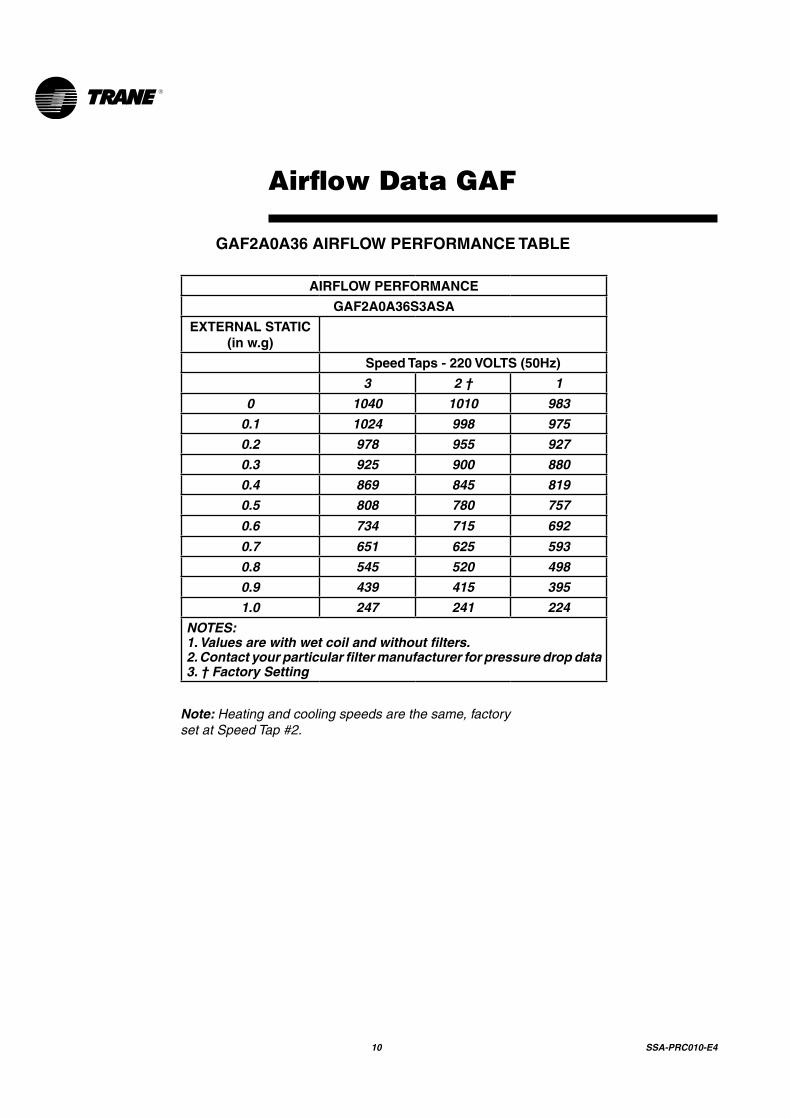
Airflow Data GAF
GAF2A0A36 AIRFLOW PERFORMANCE TABLE
Note: Heating and cooling speeds are the same, factory set at Speed Tap #2.
AIRFLOW PERFORMANCE
GAF2A0A36S3ASA
EXTERNAL STATIC (in w.g)
Speed Taps - 220 VOLTS (50Hz)
3 2 † 1
0 1040 1010 983
0.1 1024 998 975
0.2 978 955 927
0.3 925 900 880
0.4 869 845 819
0.5 808 780 757
0.6 734 715 692
0.7 651 625 593
0.8 545 520 498
0.9 439 415 395
1.0 247 241 224
NOTES:1. Values are with wet coil and without filters.2. Contact your particular filter manufacturer for pressure drop data3. † Factory Setting

SSA-PRC010-E4 11
Airflow Data GAT/GAM
GAT2A0C48/ GAM2A0C48 AIRFLOW PERFORMANCE TABLE
Note: Heating and cooling speeds are the same, factory set at Speed Tap #2.
AIRFLOW PERFORMANCE
GAT2A0C48S4ASA/GAM2A0C48S4ASA
EXTERNAL STATIC (in w.g)
AIRFLOW (CFM)
Speed Taps - 220 VOLTS (50Hz)
3 2 † 1
0 1897 1815 1728
0.1 1827 1757 1676
0.2 1756 1687 1615
0.3 1682 1617 1552
0.4 1568 1532 1475
0.5 1476 1441 1390
0.6 1379 1340 1291
0.7 1258 1220 1150
0.8 1090 1050 984
0.9 915 891 783
1 682
NOTES:1. Values are with wet coil and without filters.2. Contact your particular filter manufacturer for pressure drop data.3. † Factory Setting
12 SSA-PRC010-E4
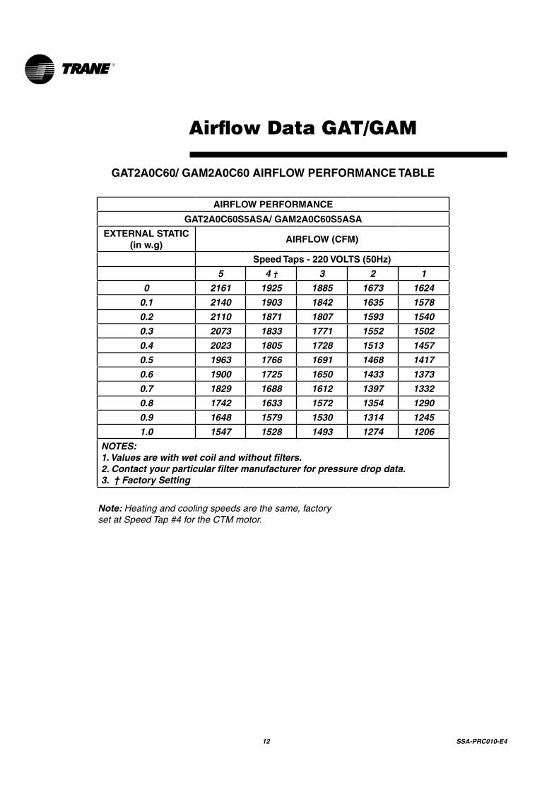
Airflow Data GAT/GAM
GAT2A0C60/ GAM2A0C60 AIRFLOW PERFORMANCE TABLE
AIRFLOW PERFORMANCE
GAT2A0C60S5ASA/ GAM2A0C60S5ASA
EXTERNAL STATIC (in w.g)
AIRFLOW (CFM)
Speed Taps - 220 VOLTS (50Hz)
5 4 † 3 2 1
0 2161 1925 1885 1673 1624
0.1 2140 1903 1842 1635 1578
0.2 2110 1871 1807 1593 1540
0.3 2073 1833 1771 1552 1502
0.4 2023 1805 1728 1513 1457
0.5 1963 1766 1691 1468 1417
0.6 1900 1725 1650 1433 1373
0.7 1829 1688 1612 1397 1332
0.8 1742 1633 1572 1354 1290
0.9 1648 1579 1530 1314 1245
1.0 1547 1528 1493 1274 1206
NOTES:1. Values are with wet coil and without filters.2. Contact your particular filter manufacturer for pressure drop data. 3. † Factory Setting
Note: Heating and cooling speeds are the same, factory set at Speed Tap #4 for the CTM motor.

SSA-PRC010-E4 13
Performance data
Outdoor model
2TTB0530AA000CA
Indoor model
GAF2A0A36S3ASA
Nominal airflow (CFM)
1000
COOLINGPERFORMANCEATINDOORDRYBULBTEMPERATURES
O.D.D.B. I.D.W.B. Total capacity 72 74 76 78 80 SYSTEM
kW
85 59 26.8 22.2 24.1 26.0 26.8 26.8 2.9
85 63 28.1 18.0 19.9 21.8 23.7 25.6 2.9
85 67 30.0 14.0 15.9 17.8 19.6 21.5 3.0
85 71 32.6 10.1 12.0 13.9 15.8 17.7 3.0
95 59 25.4 21.6 23.5 25.4 25.4 25.4 3.1
95 63 26.7 17.5 19.3 21.2 23.1 25.0 3.1
95 67 28.5 13.4 15.3 17.2 19.1 21.0 3.2
95 71 30.9 9.6 11.4 13.3 15.2 17.1 3.2
105 59 24.1 21.0 22.9 24.1 24.1 24.1 3.3
105 63 25.2 16.9 18.7 20.6 22.5 24.4 3.3
105 67 27.0 12.9 14.8 16.7 18.5 20.4 3.4
105 71 29.2 9.0 10.9 12.7 14.6 16.5 3.4
115 59 22.7 20.4 22.3 22.7 22.7 22.7 3.5
115 63 23.8 16.3 18.2 20.1 21.9 23.8 3.5
115 67 25.4 12.3 14.2 16.1 17.9 19.8 3.6
115 71 27.6 8.4 10.3 12.2 14.1 16.0 3.6
AHRIRATINGFORCOOLING
A.H.R.I. STANDARD 210/240 RATING CONDITIONS — (A) Cooling 80°F. D.B., 67°F. W.B. air entering indoor coil, 95°F. D.B. air entering outdoor coil. (B) High Temperature Heating 47°F. D.B., 43°F. W.B. air entering outdoor coil, 70°F. D.B. air entering indoor coil. (C) Low Temperature Heating 17°F. D.B.,15°F. W.B. air entering outdoor coil, 70°F. D.B. air entering indoor coil. (D) Rated indoor airflow for heating is the same as for cooling.
AIRFLOWRATE,CFM. CAPACITYMULTIPLIER TOTALPOWERMULTIPLIER
875 0.970 0.980
1125 1.030 1.020
CFM CAPACITY (A) TEST SEER EER
1025 28618 9.96 9.09
Correctionfactors-otherairflows
14 SSA-PRC010-E4
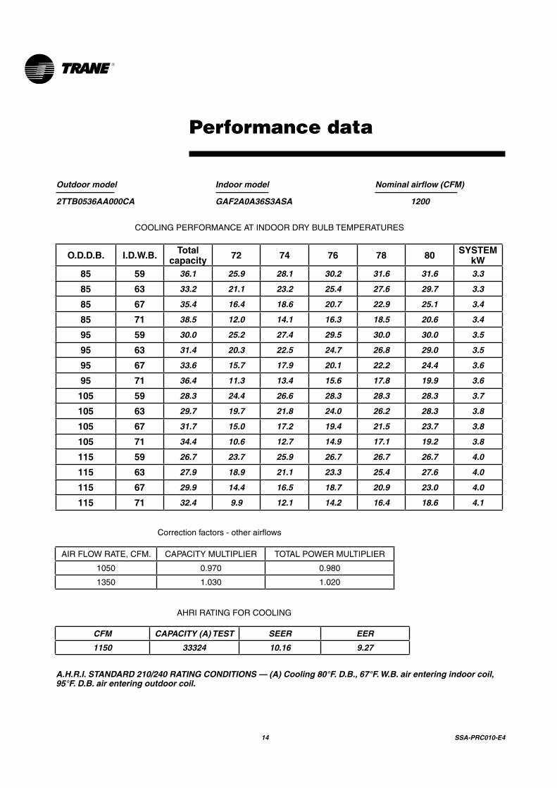
Performance data
Outdoor model
2TTB0536AA000CA
Indoor model
GAF2A0A36S3ASA
Nominal airflow (CFM)
1200
COOLINGPERFORMANCEATINDOORDRYBULBTEMPERATURES
O.D.D.B. I.D.W.B. Total capacity 72 74 76 78 80 SYSTEM
kW85 59 36.1 25.9 28.1 30.2 31.6 31.6 3.3
85 63 33.2 21.1 23.2 25.4 27.6 29.7 3.3
85 67 35.4 16.4 18.6 20.7 22.9 25.1 3.4
85 71 38.5 12.0 14.1 16.3 18.5 20.6 3.4
95 59 30.0 25.2 27.4 29.5 30.0 30.0 3.5
95 63 31.4 20.3 22.5 24.7 26.8 29.0 3.5
95 67 33.6 15.7 17.9 20.1 22.2 24.4 3.6
95 71 36.4 11.3 13.4 15.6 17.8 19.9 3.6
105 59 28.3 24.4 26.6 28.3 28.3 28.3 3.7
105 63 29.7 19.7 21.8 24.0 26.2 28.3 3.8
105 67 31.7 15.0 17.2 19.4 21.5 23.7 3.8
105 71 34.4 10.6 12.7 14.9 17.1 19.2 3.8
115 59 26.7 23.7 25.9 26.7 26.7 26.7 4.0
115 63 27.9 18.9 21.1 23.3 25.4 27.6 4.0
115 67 29.9 14.4 16.5 18.7 20.9 23.0 4.0
115 71 32.4 9.9 12.1 14.2 16.4 18.6 4.1
Correctionfactors-otherairflows
AIRFLOWRATE,CFM. CAPACITYMULTIPLIER TOTALPOWERMULTIPLIER
1050 0.970 0.980
1350 1.030 1.020
AHRIRATINGFORCOOLING
CFM CAPACITY (A) TEST SEER EER
1150 33324 10.16 9.27
A.H.R.I. STANDARD 210/240 RATING CONDITIONS — (A) Cooling 80°F. D.B., 67°F. W.B. air entering indoor coil, 95°F. D.B. air entering outdoor coil.
SSA-PRC010-E4 15
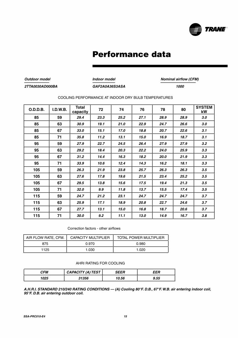
Performance data
Outdoor model
2TTA0030AD000BA
Indoor model
GAF2A0A36S3ASA
Nominal airflow (CFM)
1000
COOLINGPERFORMANCEATINDOORDRYBULBTEMPERATURES
O.D.D.B. I.D.W.B. Total capacity 72 74 76 78 80 SYSTEM
kW85 59 29.4 23.3 25.2 27.1 28.9 28.9 3.0
85 63 30.9 19.1 21.0 22.9 24.7 26.6 3.0
85 67 33.0 15.1 17.0 18.8 20.7 22.6 3.1
85 71 35.8 11.2 13.1 15.0 16.9 18.7 3.1
95 59 27.9 22.7 24.5 26.4 27.9 27.9 3.2
95 63 29.2 18.4 20.3 22.2 24.0 25.9 3.3
95 67 31.2 14.4 16.3 18.2 20.0 21.9 3.3
95 71 33.9 10.6 12.4 14.3 16.2 18.1 3.3
105 59 26.3 21.9 23.8 25.7 26.3 26.3 3.5
105 63 27.6 17.8 19.6 21.5 23.4 25.2 3.5
105 67 29.5 13.8 15.6 17.5 19.4 21.3 3.5
105 71 32.0 9.9 11.8 13.7 15.5 17.4 3.5
115 59 24.7 21.2 23.1 24.7 24.7 24.7 3.7
115 63 25.9 17.1 18.9 20.8 22.7 24.6 3.7
115 67 27.7 13.1 15.0 16.8 18.7 20.6 3.7
115 71 30.0 9.2 11.1 13.0 14.9 16.7 3.8
Correctionfactors-otherairflows
AIRFLOWRATE,CFM. CAPACITYMULTIPLIER TOTALPOWERMULTIPLIER
875 0.970 0.980
1125 1.030 1.020
AHRIRATINGFORCOOLING
CFM CAPACITY (A) TEST SEER EER
1025 31356 10.56 9.55
A.H.R.I. STANDARD 210/240 RATING CONDITIONS — (A) Cooling 80°F. D.B., 67°F. W.B. air entering indoor coil, 95°F. D.B. air entering outdoor coil.
16 SSA-PRC010-E4
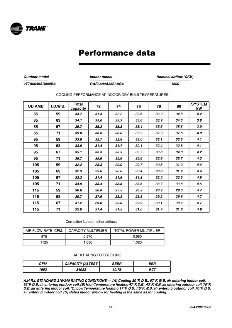
Performance data
Outdoor model
2TTA0040AD000BA
Indoor model
GAF2A00A36S3ASA
Nominal airflow (CFM)
1600
COOLINGPERFORMANCEATINDOORDRYBULBTEMPERATURES
OD AMB I.D.W.B. Total capacity 72 74 76 78 80 SYSTEM
kW85 59 33.7 31.3 32.2 32.6 33.9 34.8 4.2
85 63 34.1 33.0 33.3 33.6 33.9 34.3 3.8
85 67 36.7 35.2 35.3 35.4 35.5 35.6 3.9
85 71 39.0 38.0 38.0 37.9 37.9 37.8 4.0
95 59 33.8 32.7 32.8 33.0 33.1 33.3 4.1
95 63 33.9 31.4 31.7 32.1 32.4 32.8 4.1
95 67 35.1 33.3 33.5 33.7 33.8 34.0 4.2
95 71 36.7 35.6 35.6 35.6 35.6 35.7 4.3
105 59 32.2 28.3 29.0 29.7 30.5 31.2 4.4
105 63 32.3 29.6 30.0 30.4 30.8 31.2 4.4
105 67 33.3 31.4 31.6 31.8 32.0 32.3 4.5
105 71 34.9 33.4 33.5 33.6 33.7 33.8 4.6
115 59 30.6 26.8 27.5 28.2 28.9 29.6 4.7
115 63 30.7 27.9 28.3 28.8 29.2 29.6 4.7
115 67 31.2 29.6 29.8 29.9 30.1 30.2 4.7
115 71 32.9 31.4 31.5 31.6 31.7 31.8 4.9
Correctionfactors-otherairflows
AIRFLOWRATE,CFM. CAPACITYMULTIPLIER TOTALPOWERMULTIPLIER
875 0.970 0.980
1125 1.030 1.020
AHRIRATINGFORCOOLING
CFM CAPACITY (A) TEST SEER EER
1662 34023 10.75 9.77
A.H.R.I. STANDARD 210/240 RATING CONDITIONS — (A) Cooling 80°F. D.B., 67°F. W.B. air entering indoor coil, 95°F. D.B. air entering outdoor coil. (B) High Temperature Heating 47°F. D.B., 43°F. W.B. air entering outdoor coil, 70°F. D.B. air entering indoor coil. (C) Low Temperature Heating 17°F. D.B. ,15°F. W.B. air entering outdoor coil, 70°F. D.B. air entering indoor coil. (D) Rated indoor airflow for heating is the same as for cooling.

SSA-PRC010-E4 17
Performance data
Outdoor model
2TTA0040AD000BA
Indoor model
GAT2A0B48S4ASA/ GAM2A0B48S4ASA
Nominal airflow (CFM)
1400
COOLINGPERFORMANCEATINDOORDRYBULBTEMPERATURES
O.D.D.B. I.D.W.B. Total capacity 72 74 76 78 80 SYSTEM
kW85 59 37.4 31.8 34.6 37.3 37.4 37.4 3.9
85 63 39.2 25.7 28.4 31.2 33.9 36.7 4.0
85 67 41.9 19.8 22.5 25.3 28.1 30.8 4.0
85 71 45.4 14.1 16.9 19.6 22.4 25.1 4.0
95 59 35.4 30.9 33.7 35.4 35.4 35.4 4.2
95 63 37.1 24.8 27.6 30.3 33.1 35.8 4.2
95 67 39.7 19.0 21.7 24.5 27.2 30.0 4.3
95 71 43.0 13.3 16.0 18.8 21.5 24.3 4.3
105 59 33.4 30.0 32.8 33.4 33.4 33.4 4.5
105 63 35.1 24.0 26.8 29.5 32.3 35.0 4.5
105 67 37.5 18.2 20.9 23.7 26.4 29.2 4.5
105 71 40.6 12.5 15.2 18.0 20.7 23.5 4.6
115 59 31.5 29.2 31.5 31.5 31.5 31.5 4.7
115 63 33.0 23.2 25.9 28.7 31.4 33.0 4.8
115 67 35.3 17.4 20.1 22.9 25.6 28.4 4.8
115 71 38.2 11.7 14.4 17.2 19.9 22.7 4.9
Correctionfactors-otherairflows
AIRFLOWRATE,CFM. CAPACITYMULTIPLIER TOTALPOWERMULTIPLIER
1225 0.970 0.980
1575 1.030 1.020
AHRIRATINGFORCOOLING
CFM CAPACITY (A) TEST SEER EER
1375 39529 10.16 9.25
A.H.R.I. STANDARD 210/240 RATING CONDITIONS — (A) Cooling 80°F. D.B., 67°F. W.B. air entering indoor coil, 95°F. D.B. air entering outdoor coil.
18 SSA-PRC010-E4
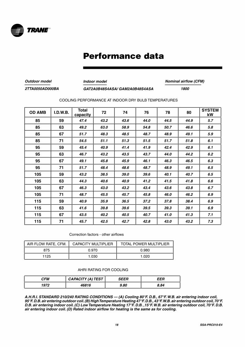
Performance data
Outdoor model
2TTA0050AD000BA
Indoor model
GAT2A0B48S4ASA/ GAM2A0B48S4ASA
Nominal airflow (CFM)
1800
COOLINGPERFORMANCEATINDOORDRYBULBTEMPERATURES
OD AMB I.D.W.B. Total capacity 72 74 76 78 80 SYSTEM
kW85 59 47.4 43.2 43.6 44.0 44.5 44.9 5.7
85 63 49.2 63.0 58.9 54.8 50.7 46.6 5.8
85 67 51.7 48.3 48.5 48.7 48.9 49.1 5.9
85 71 54.5 51.1 51.3 51.5 51.7 51.8 6.1
95 59 45.4 40.9 41.4 41.9 42.4 42.9 6.1
95 63 46.7 43.2 43.5 43.7 44.0 44.2 6.2
95 67 49.1 45.8 45.9 46.1 46.3 46.5 6.3
95 71 51.7 48.4 48.6 48.7 48.9 49.1 6.5
105 59 43.2 38.5 39.0 39.6 40.1 40.7 6.5
105 63 44.3 40.6 40.9 41.2 41.5 41.8 6.6
105 67 46.3 43.0 43.2 43.4 43.6 43.8 6.7
105 71 48.7 45.5 45.7 45.8 46.0 46.2 6.9
115 59 40.9 35.9 36.5 37.2 37.8 38.4 6.9
115 63 41.6 39.8 39.6 39.5 39.3 39.1 6.9
115 67 43.5 40.2 40.5 40.7 41.0 41.3 7.1
115 71 45.7 42.5 42.7 42.8 43.0 43.2 7.3
Correctionfactors-otherairflows
AIRFLOWRATE,CFM. CAPACITYMULTIPLIER TOTALPOWERMULTIPLIER
875 0.970 0.980
1125 1.030 1.020
AHRIRATINGFORCOOLING
CFM CAPACITY (A) TEST SEER EER
1972 46816 9.80 8.84
A.H.R.I. STANDARD 210/240 RATING CONDITIONS — (A) Cooling 80°F. D.B., 67°F. W.B. air entering indoor coil, 95°F. D.B. air entering outdoor coil. (B) High Temperature Heating 47°F. D.B., 43°F. W.B. air entering outdoor coil, 70°F. D.B. air entering indoor coil. (C) Low Temperature Heating 17°F. D.B. ,15°F. W.B. air entering outdoor coil, 70°F. D.B. air entering indoor coil. (D) Rated indoor airflow for heating is the same as for cooling.

SSA-PRC010-E4 19
Outdoor model
2TTA0050AD000BA
Indoor model
GAT2A0C60S5ASA/ GAM2A0C60S5ASA
Nominal airflow (CFM)
1600
COOLINGPERFORMANCEATINDOORDRYBULBTEMPERATURES
O.D.D.B. I.D.W.B. Total capacity 72 74 76 78 80 SYSTEM
kW85 59 45.3 38.1 41.3 44.5 45.3 45.3 5.1
85 63 47.5 30.9 34.1 37.3 40.6 43.8 5.1
85 67 50.8 24.0 27.2 30.4 33.7 36.9 5.1
85 71 55.1 17.3 20.5 23.8 27.0 30.2 5.2
95 59 42.9 37.0 40.2 42.9 42.9 42.9 5.4
95 63 45.0 29.8 33.1 36.3 39.5 42.8 5.4
95 67 48.1 22.9 26.2 29.4 32.7 35.9 5.5
95 71 52.2 16.3 19.5 22.8 26.0 29.2 5.5
105 59 40.6 36.0 39.2 40.6 40.6 40.6 5.7
105 63 42.5 28.8 32.0 35.3 38.5 41.7 5.8
105 67 45.4 21.9 25.2 28.4 31.6 34.9 5.8
105 71 49.3 15.3 18.5 21.8 25.0 28.2 5.9
115 59 38.2 34.9 38.2 38.2 38.2 38.2 6.1
115 63 40.0 27.8 31.0 34.3 37.5 40.0 6.1
115 67 42.8 21.0 24.2 27.4 30.7 33.9 6.2
115 71 46.4 14.3 17.6 20.8 24.0 27.3 6.2
Correctionfactors-otherairflows
AIRFLOWRATE,CFM. CAPACITYMULTIPLIER TOTALPOWERMULTIPLIER
1400 0.970 0.980
1800 1.030 1.020
AHRIRATINGFORCOOLING
CFM CAPACITY (A) TEST SEER EER
1650 48364 9.70 8.85
A.H.R.I. STANDARD 210/240 RATING CONDITIONS — (A) Cooling 80°F. D.B., 67°F. W.B. air entering indoor coil, 95°F. D.B. air entering outdoor coil.
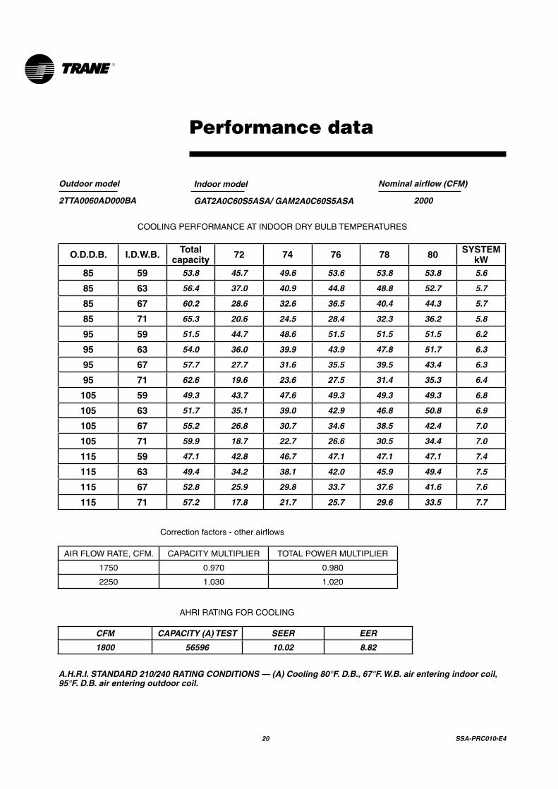
Performancedata
20 SSA-PRC010-E4
Outdoor model
2TTA0060AD000BA
Indoor model
GAT2A0C60S5ASA/ GAM2A0C60S5ASA
Nominal airflow (CFM)
2000
COOLINGPERFORMANCEATINDOORDRYBULBTEMPERATURES
O.D.D.B. I.D.W.B. Total capacity 72 74 76 78 80 SYSTEM
kW85 59 53.8 45.7 49.6 53.6 53.8 53.8 5.6
85 63 56.4 37.0 40.9 44.8 48.8 52.7 5.7
85 67 60.2 28.6 32.6 36.5 40.4 44.3 5.7
85 71 65.3 20.6 24.5 28.4 32.3 36.2 5.8
95 59 51.5 44.7 48.6 51.5 51.5 51.5 6.2
95 63 54.0 36.0 39.9 43.9 47.8 51.7 6.3
95 67 57.7 27.7 31.6 35.5 39.5 43.4 6.3
95 71 62.6 19.6 23.6 27.5 31.4 35.3 6.4
105 59 49.3 43.7 47.6 49.3 49.3 49.3 6.8
105 63 51.7 35.1 39.0 42.9 46.8 50.8 6.9
105 67 55.2 26.8 30.7 34.6 38.5 42.4 7.0
105 71 59.9 18.7 22.7 26.6 30.5 34.4 7.0
115 59 47.1 42.8 46.7 47.1 47.1 47.1 7.4
115 63 49.4 34.2 38.1 42.0 45.9 49.4 7.5
115 67 52.8 25.9 29.8 33.7 37.6 41.6 7.6
115 71 57.2 17.8 21.7 25.7 29.6 33.5 7.7
Correctionfactors-otherairflows
AIRFLOWRATE,CFM. CAPACITYMULTIPLIER TOTALPOWERMULTIPLIER
1750 0.970 0.980
2250 1.030 1.020
AHRIRATINGFORCOOLING
CFM CAPACITY (A) TEST SEER EER
1800 56596 10.02 8.82
A.H.R.I. STANDARD 210/240 RATING CONDITIONS — (A) Cooling 80°F. D.B., 67°F. W.B. air entering indoor coil, 95°F. D.B. air entering outdoor coil.
Performance data

SSA-PRC010-E4 21
Outdoor model
2TWB0030AA000BA
Indoor model
GAF2A0A36S3ASA
Nominal airflow (CFM)
1000
COOLINGPERFORMANCEATINDOORDRYBULBTEMPERATURES
O.D.D.B. I.D.W.B. Total capacity 72 74 76 78 80 SYSTEM
kW85 59 26.4 22.1 24.0 25.9 26.4 26.4 2.9
85 63 27.7 17.9 19.8 21.7 23.5 25.4 2.9
85 67 29.6 13.9 15.7 17.6 19.5 21.4 2.9
85 71 32.1 10.0 11.9 13.7 15.6 17.5 3.0
95 59 25.0 21.5 23.4 25.0 25.0 25.0 3.1
95 63 26.3 17.3 19.2 21.1 23.0 24.9 3.1
95 67 28.0 13.3 15.2 17.0 18.9 20.8 3.2
95 71 30.4 9.4 11.3 13.2 15.1 16.9 3.2
105 59 23.7 20.9 22.8 23.7 23.7 23.7 3.3
105 63 24.8 16.7 18.6 20.5 22.4 24.3 3.3
105 67 26.5 12.7 14.6 16.5 18.4 20.3 3.4
105 71 28.8 8.8 10.7 12.6 14.5 16.4 3.4
115 59 22.3 20.3 22.2 22.3 22.3 22.3 3.5
115 63 23.4 16.2 18.0 19.9 21.8 23.4 3.5
115 67 25.0 12.2 14.1 15.9 17.8 19.7 3.6
115 71 27.1 8.3 10.2 12.1 13.9 15.8 3.6
Correctionfactors-otherairflows
AIRFLOWRATE,CFM. CAPACITYMULTIPLIER TOTALPOWERMULTIPLIER
875 0.970 0.980
1125 1.030 1.020
AHRIRATINGFORCOOLING
CFM CAPACITY (A) TEST SEER EER
1025 28172 9.88 8.98
A.H.R.I. STANDARD 210/240 RATING CONDITIONS — (A) Cooling 80°F. D.B., 67°F. W.B. air entering indoor coil, 95°F. D.B. air entering outdoor coil.
Performance data

22 SSA-PRC010-E4
Outdoor model
2TWB0036AA000BA
Indoor model
GAF2A0A36S3ASA
Nominal airflow (CFM)
1200
COOLINGPERFORMANCEATINDOORDRYBULBTEMPERATURES
O.D.D.B. I.D.W.B. Total capacity 72 74 76 78 80 SYSTEM
kW85 59 32.6 26.3 28.4 30.6 32.6 32.6 3.4
85 63 34.2 21.4 23.6 25.7 27.9 30.0 3.4
85 67 36.5 16.8 18.9 21.1 23.2 25.4 3.4
85 71 39.6 12.3 14.5 16.6 18.8 21.0 3.5
95 59 31.0 25.5 27.7 29.8 31.0 31.0 3.6
95 63 32.5 20.7 22.9 25.0 27.2 29.3 3.7
95 67 34.8 16.1 18.3 20.5 22.6 24.8 3.7
95 71 37.7 11.7 13.8 16.0 18.1 20.3 3.7
105 59 29.5 24.9 27.0 29.2 29.5 29.5 3.9
105 63 30.9 20.1 22.2 24.4 26.5 28.7 3.9
105 67 33.0 15.5 17.6 19.8 21.9 24.1 3.9
105 71 35.8 11.0 13.2 15.3 17.5 19.7 4.0
115 59 27.9 24.2 26.3 27.9 27.9 27.9 4.1
115 63 29.2 19.4 21.5 23.7 25.8 28.0 4.1
115 67 31.2 14.8 17.0 19.1 21.3 23.4 4.2
115 71 33.9 10.4 12.6 14.7 16.9 19.0 4.2
Correctionfactors-otherairflows
AIRFLOWRATE,CFM. CAPACITYMULTIPLIER TOTALPOWERMULTIPLIER
1050 0.970 0.980
1350 1.030 1.020
AHRIRATINGFORCOOLING
CFM CAPACITY (A) TEST SEER EER
1150 34491 10.22 9.32
A.H.R.I. STANDARD 210/240 RATING CONDITIONS — (A) Cooling 80°F. D.B., 67°F. W.B. air entering indoor coil, 95°F. D.B. air entering outdoor coil.
Performance data

SSA-PRC010-E4 23
Outdoor model
2TWA0040AD000BA
Indoor model
GAF2A00A36S3ASA
Nominal airflow (CFM)
1600
COOLINGPERFORMANCEATINDOORDRYBULBTEMPERATURES
OD AMB I.D.W.B. Total capacity 72 74 76 78 80 SYSTEM
kW85 59 35.9 31.9 32.6 33.4 34.1 34.8 3.9
85 63 36.0 33.7 34.0 34.3 34.6 34.9 3.9
85 67 37.5 35.8 35.9 36.1 36.2 36.4 4.0
85 71 39.6 38.0 38.1 38.2 38.3 38.4 4.1
95 59 34.4 30.4 31.1 31.9 32.6 33.4 4.2
95 63 34.5 32.0 32.4 32.7 33.1 33.4 4.2
95 67 35.7 34.0 34.2 34.3 34.5 34.6 4.3
95 71 37.7 36.1 36.2 36.3 36.4 36.5 4.4
105 59 32.8 28.9 29.6 30.3 31.1 31.8 4.5
105 63 32.9 30.3 30.7 31.1 31.5 31.9 4.5
105 67 33.8 32.2 32.3 32.5 32.6 32.8 4.6
105 71 35.6 34.1 34.2 34.3 34.4 34.5 4.7
115 59 31.2 27.2 28.0 28.7 29.4 30.2 4.8
115 63 31.2 28.5 28.9 29.3 29.8 30.2 4.8
115 67 31.9 30.2 30.4 30.5 30.7 30.9 4.9
115 71 33.6 32.1 32.2 32.3 32.4 32.5 5.0
AHRIRATINGFORCOOLING
CFM CAPACITY (A) TEST SEER EER
1662 34781 10.21 9.68
A.H.R.I. STANDARD 210/240 RATING CONDITIONS — (A) Cooling 80°F. D.B., 67°F. W.B. air entering indoor coil, 95°F. D.B. air entering outdoor coil. (B) High Temperature Heating 47°F. D.B., 43°F. W.B. air entering outdoor coil, 70°F. D.B. air entering indoor coil. (C) Low Temperature Heating 17°F. D.B. ,15°F. W.B. air entering outdoor coil, 70°F. D.B. air entering indoor coil. (D) Rated indoor airflow for heating is the same as for cooling.
Performance data

24 SSA-PRC010-E4
Outdoor model
2TWA0050AD000BA
Indoor model
GAT2A0B48S4ASA/ GAM2A0B48S4ASA
COOLINGPERFORMANCEATINDOORDRYBULBTEMPERATURES
OD AMB I.D.W.B. Total capacity 72 74 76 78 80 SYSTEM
kW85 59 48.0 43.5 44.0 44.5 45.0 45.4 5.3
85 63 49.8 46.1 46.4 46.6 46.9 47.2 5.4
85 67 52.4 48.8 49.0 49.3 49.5 49.8 5.5
85 71 55.3 51.7 51.9 52.2 52.4 52.6 5.6
95 59 45.9 41.4 41.9 42.4 42.9 43.4 5.7
95 63 47.5 43.8 44.1 44.4 44.6 44.9 5.8
95 67 49.9 46.4 46.6 46.9 47.1 47.3 5.9
95 71 52.7 49.1 49.4 49.6 49.8 50.1 6.0
105 59 43.9 39.1 39.7 40.3 40.8 41.4 6.1
105 63 45.1 41.3 41.6 42.0 42.3 42.6 6.1
105 67 47.3 35.5 37.8 40.1 42.4 44.8 6.2
105 71 49.9 46.4 46.6 46.8 47.1 47.3 6.4
115 59 41.6 36.7 37.3 37.9 38.5 39.2 6.4
115 63 42.5 38.7 39.0 39.4 39.7 40.1 6.5
115 67 44.5 41.0 41.3 41.5 41.7 42.0 6.6
115 71 46.9 43.4 43.6 43.9 44.1 44.3 6.8
AHRIRATINGFORCOOLING
CFM CAPACITY (A) TEST SEER EER
1792 47449 10.16 9.66
A.H.R.I. STANDARD 210/240 RATING CONDITIONS — (A) Cooling 80°F. D.B., 67°F. W.B. air entering indoor coil, 95°F. D.B. air entering outdoor coil. (B) High Temperature Heating 47°F. D.B., 43°F. W.B. air entering outdoor coil, 70°F. D.B. air entering indoor coil. (C) Low Temperature Heating 17°F. D.B. ,15°F. W.B. air entering outdoor coil, 70°F. D.B. air entering indoor coil. (D) Rated indoor airflow for heating is the same as for cooling.
Nominal airflow (CFM)
1800
Performance data

SSA-PRC010-E4 25
Outdoor model
2TWA0040AD000BA
Indoor model
GAT2A0B48S4ASA/ GAM2A0B48S4ASA
Nominal airflow (CFM)
1400
COOLINGPERFORMANCEATINDOORDRYBULBTEMPERATURES
O.D.D.B. I.D.W.B. Total capacity 72 74 76 78 80 SYSTEM
kW85 59 37.1 31.7 34.4 37.1 37.1 37.1 3.8
85 63 38.9 25.6 28.3 31.1 33.8 36.6 3.9
85 67 41.5 19.7 22.4 25.2 27.9 30.7 3.9
85 71 45.1 14.0 16.8 19.5 22.3 25.0 3.9
95 59 35.2 30.8 33.6 35.2 35.2 35.2 4.1
95 63 36.9 24.7 27.5 30.3 33.0 35.8 4.1
95 67 39.4 18.9 21.6 24.4 27.1 29.9 4.2
95 71 42.8 13.2 16.0 18.7 21.5 24.2 4.2
105 59 33.3 30.0 32.8 33.3 33.3 33.3 4.4
105 63 34.9 23.9 26.7 29.4 32.2 34.9 4.4
105 67 37.3 18.1 20.9 23.6 26.4 29.1 4.4
105 71 40.4 12.4 15.2 17.9 20.7 23.4 4.5
115 59 31.4 29.2 31.4 31.4 31.4 31.4 4.6
115 63 32.9 23.1 25.9 28.7 31.4 32.9 4.7
115 67 35.2 17.3 20.1 22.8 25.6 28.4 4.7
115 71 38.1 11.6 14.4 17.2 19.9 22.7 4.8
Correctionfactors-otherairflows
AIRFLOWRATE,CFM. CAPACITYMULTIPLIER TOTALPOWERMULTIPLIER
1225 0.970 0.980
1575 1.030 1.020
AHRIRATINGFORCOOLING
CFM CAPACITY (A) TEST SEER EER
1375 39277 10.37 9.41
A.H.R.I. STANDARD 210/240 RATING CONDITIONS — (A) Cooling 80°F. D.B., 67°F. W.B. air entering indoor coil, 95°F. D.B. air entering outdoor coil.
Performance data
26 SSA-PRC010-E4
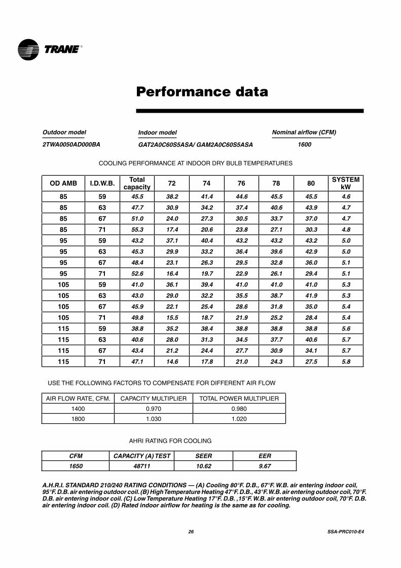
Outdoor model
2TWA0050AD000BA
Indoor model
GAT2A0C60S5ASA/ GAM2A0C60S5ASA
Nominal airflow (CFM)
1600
COOLINGPERFORMANCEATINDOORDRYBULBTEMPERATURES
OD AMB I.D.W.B. Total capacity 72 74 76 78 80 SYSTEM
kW85 59 45.5 38.2 41.4 44.6 45.5 45.5 4.6
85 63 47.7 30.9 34.2 37.4 40.6 43.9 4.7
85 67 51.0 24.0 27.3 30.5 33.7 37.0 4.7
85 71 55.3 17.4 20.6 23.8 27.1 30.3 4.8
95 59 43.2 37.1 40.4 43.2 43.2 43.2 5.0
95 63 45.3 29.9 33.2 36.4 39.6 42.9 5.0
95 67 48.4 23.1 26.3 29.5 32.8 36.0 5.1
95 71 52.6 16.4 19.7 22.9 26.1 29.4 5.1
105 59 41.0 36.1 39.4 41.0 41.0 41.0 5.3
105 63 43.0 29.0 32.2 35.5 38.7 41.9 5.3
105 67 45.9 22.1 25.4 28.6 31.8 35.0 5.4
105 71 49.8 15.5 18.7 21.9 25.2 28.4 5.4
115 59 38.8 35.2 38.4 38.8 38.8 38.8 5.6
115 63 40.6 28.0 31.3 34.5 37.7 40.6 5.7
115 67 43.4 21.2 24.4 27.7 30.9 34.1 5.7
115 71 47.1 14.6 17.8 21.0 24.3 27.5 5.8
USETHEFOLLOWINGFACTORSTOCOMPENSATEFORDIFFERENTAIRFLOW
AIRFLOWRATE,CFM. CAPACITYMULTIPLIER TOTALPOWERMULTIPLIER
1400 0.970 0.980
1800 1.030 1.020
AHRIRATINGFORCOOLING
CFM CAPACITY (A) TEST SEER EER
1650 48711 10.62 9.67
A.H.R.I. STANDARD 210/240 RATING CONDITIONS — (A) Cooling 80°F. D.B., 67°F. W.B. air entering indoor coil, 95°F. D.B. air entering outdoor coil. (B) High Temperature Heating 47°F. D.B., 43°F. W.B. air entering outdoor coil, 70°F. D.B. air entering indoor coil. (C) Low Temperature Heating 17°F. D.B. ,15°F. W.B. air entering outdoor coil, 70°F. D.B. air entering indoor coil. (D) Rated indoor airflow for heating is the same as for cooling.
Performance data

SSA-PRC010-E4 27
Outdoor model
2TWA0060AD000BA
Indoor model
GAT2A0C60S5ASA/ GAM2A0C60S5ASA
Nominal airflow (CFM)
2000
COOLINGPERFORMANCEATINDOORDRYBULBTEMPERATURES
O.D.D.B. I.D.W.B. Total capacity 72 74 76 78 80 SYSTEM
kW85 59 52.5 45.2 49.1 52.5 52.5 52.5 5.1
85 63 55.0 36.4 40.4 44.3 48.2 52.1 5.2
85 67 58.8 28.1 32.0 36.0 39.9 43.8 5.2
85 71 63.8 20.1 24.0 27.9 31.8 35.7 5.3
95 59 50.3 44.2 48.1 50.3 50.3 50.3 5.6
95 63 52.7 35.5 39.4 43.3 47.3 51.2 5.7
95 67 56.3 27.2 31.1 35.0 39.0 42.9 5.7
95 71 61.1 19.1 23.1 27.0 30.9 34.8 5.8
105 59 48.0 43.2 47.1 48.0 48.0 48.0 6.1
105 63 50.4 34.6 38.5 42.4 46.3 50.3 6.2
105 67 53.8 26.3 30.2 34.1 38.0 41.9 6.2
105 71 58.4 18.2 22.2 26.1 30.0 33.9 6.3
115 59 45.8 42.2 45.8 45.8 45.8 45.8 6.6
115 63 48.0 33.6 37.5 41.5 45.4 48.0 6.6
115 67 51.3 25.4 29.3 33.2 37.1 41.0 6.7
115 71 55.7 17.3 21.2 25.2 29.1 33.0 6.8
USETHEFOLLOWINGFACTORSTOCOMPENSATEFORDIFFERENTAIRFLOW
AIRFLOWRATE,CFM. CAPACITYMULTIPLIER TOTALPOWERMULTIPLIER
1750 0.970 0.980
2250 1.030 1.020
AHRIRATINGFORCOOLING
CFM CAPACITY (A) TEST SEER EER
1800 55196 10.64 9.51
A.H.R.I. STANDARD 210/240 RATING CONDITIONS — (A) Cooling 80°F. D.B., 67°F. W.B. air entering indoor coil, 95°F. D.B. air entering outdoor coil. (B) High Temperature Heating 47°F. D.B., 43°F. W.B. air entering outdoor coil, 70°F. D.B. air entering indoor coil. (C) Low Temperature Heating 17°F. D.B. ,15°F. W.B. air entering outdoor coil, 70°F. D.B. air entering indoor coil. (D) Rated indoor airflow for heating is the same as for cooling.
Performance data

28 SSA-PRC010-E4
Outdoor model
2TWB0030AA000BA
Indoor model
GAF2A0A36S3ASA
Nominal airflow (CFM)
1000
HEATINGPERFORMANCEATINDOORDRYBULBTEMPERATURES
TOTAL CAPACITY MBH. TOTAL POWER IN KILOWATTS
OD AMB 60 70 75 80 60 70 75 80
2 10.7 10.5 10.4 10.3 1.9 2.0 2.0 2.0
7 12.7 12.5 12.4 12.3 1.9 2.0 2.1 2.1
12 14.8 14.5 14.4 14.2 2.0 2.1 2.2 2.2
17 16.8 16.5 16.3 16.2 2.1 2.2 2.2 2.3
22 18.1 17.8 17.6 17.4 2.1 2.2 2.3 2.3
27 19.4 19.1 18.9 18.7 2.2 2.3 2.4 2.4
32 20.7 20.4 20.2 20.0 2.3 2.4 2.4 2.5
37 22.8 22.4 22.1 21.9 2.3 2.4 2.5 2.6
42 25.9 25.5 25.2 25.0 2.4 2.5 2.6 2.7
47 29.1 28.5 28.3 28.0 2.5 2.6 2.7 2.8
52 31.1 30.6 30.3 30.0 2.6 2.7 2.8 2.8
57 33.2 32.6 32.3 31.9 2.7 2.8 2.9 2.9
62 35.2 34.6 34.2 33.9 2.7 2.9 2.9 3.0
67 37.3 36.6 36.2 35.9 2.8 2.9 3.0 3.1
72 39.3 38.6 38.2 37.8 2.9 3.0 3.1 3.2
USETHEFOLLOWINGFACTORSTOCOMPENSATEFORDIFFERENTAIRFLOW
AIRFLOWRATE,CFM. CAPACITYMULTIPLIER TOTALPOWERMULTIPLIER
875 0.987 0.975
1125 1.011 1.025
AHRIRATINGFORHEATING
A.H.R.I. STANDARD 210/240 RATING CONDITIONS — High Temperature Heating 47°F. D.B., 43°F. W.B. air entering outdoor coil, 70°F. D.B. air entering indoor coil.
Performance data
CFM CAPACITY 47 COP 47 CAPACITY 17 COP 17 HSPF
1025 28637 3.18 16557 2.22 7.91

SSA-PRC010-E4 29
Outdoor model
2TWB0036AA000BA
Indoor model
GAF2A0A36S3ASA
Nominal airflow (CFM)
1200
HEATINGPERFORMANCEATINDOORDRYBULBTEMPERATURES
TOTAL CAPACITY MBH. TOTAL POWER IN KILOWATTS
OD AMB 60 70 75 80 60 70 75 80
2 11.7 11.5 11.4 11.3 2.1 2.2 2.3 2.3
7 14.5 14.2 14.1 13.9 2.2 2.3 2.4 2.4
12 17.3 17.0 16.8 16.6 2.4 2.5 2.5 2.6
17 20.1 19.7 19.5 19.3 2.5 2.6 2.6 2.7
22 21.9 21.5 21.3 21.1 2.6 2.7 2.8 2.8
27 23.8 23.4 23.1 22.9 2.7 2.8 2.9 2.9
32 25.7 25.2 25.0 24.7 2.8 2.9 3.0 3.0
37 28.5 27.9 27.7 27.4 2.9 3.0 3.1 3.2
42 32.6 32.0 31.7 31.4 3.0 3.2 3.3 3.3
47 36.8 36.1 35.8 35.4 3.2 3.3 3.4 3.5
52 39.6 38.9 38.5 38.1 3.3 3.5 3.5 3.6
57 42.4 41.6 41.2 40.8 3.4 3.6 3.7 3.8
62 45.2 44.3 43.9 43.5 3.5 3.7 3.8 3.9
67 48.0 47.1 46.6 46.2 3.6 3.8 3.9 4.0
72 50.8 49.8 49.3 48.9 3.7 3.9 4.0 4.1
USETHEFOLLOWINGFACTORSTOCOMPENSATEFORDIFFERENTAIRFLOW
AIRFLOWRATE,CFM. CAPACITYMULTIPLIER TOTALPOWERMULTIPLIER
1050 0.987 0.975
1350 1.011 1.025
AHRIRATINGFORHEATING
A.H.R.I. STANDARD 210/240 RATING CONDITIONS — High Temperature Heating 47°F. D.B., 43°F. W.B. air entering outdoor coil, 70°F. D.B. air entering indoor coil.
Performance data
CFM CAPACITY 47 COP 47 CAPACITY 17 COP 17 HSPF
1150 36002 3.20 19625 2.24 7.94
30 SSA-PRC010-E4
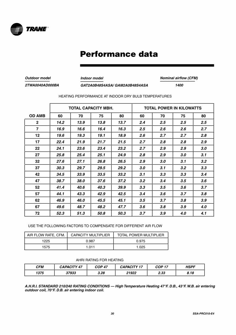
Outdoor model
2TWA0040AD000BA
Indoor model
GAT2A0B48S4ASA/ GAM2A0B48S4ASA
Nominal airflow (CFM)
1400
HEATINGPERFORMANCEATINDOORDRYBULBTEMPERATURES
TOTAL CAPACITY MBH. TOTAL POWER IN KILOWATTS
OD AMB 60 70 75 80 60 70 75 80
2 14.2 13.9 13.8 13.7 2.4 2.5 2.5 2.5
7 16.9 16.6 16.4 16.3 2.5 2.6 2.6 2.7
12 19.6 19.3 19.1 18.9 2.6 2.7 2.7 2.8
17 22.4 21.9 21.7 21.5 2.7 2.8 2.8 2.9
22 24.1 23.6 23.4 23.2 2.7 2.9 2.9 3.0
27 25.8 25.4 25.1 24.9 2.8 2.9 3.0 3.1
32 27.6 27.1 26.8 26.5 2.9 3.0 3.1 3.2
37 30.3 29.7 29.5 29.2 3.0 3.1 3.2 3.3
42 34.5 33.9 33.5 33.2 3.1 3.3 3.3 3.4
47 38.7 38.0 37.6 37.2 3.2 3.4 3.5 3.6
52 41.4 40.6 40.3 39.9 3.3 3.5 3.6 3.7
57 44.1 43.3 42.9 42.5 3.4 3.6 3.7 3.8
62 46.9 46.0 45.5 45.1 3.5 3.7 3.8 3.9
67 49.6 48.7 48.2 47.7 3.6 3.8 3.9 4.0
72 52.3 51.3 50.8 50.3 3.7 3.9 4.0 4.1
USETHEFOLLOWINGFACTORSTOCOMPENSATEFORDIFFERENTAIRFLOW
AIRFLOWRATE,CFM. CAPACITYMULTIPLIER TOTALPOWERMULTIPLIER
1225 0.987 0.975
1575 1.011 1.025
AHRIRATINGFORHEATING
A.H.R.I. STANDARD 210/240 RATING CONDITIONS — High Temperature Heating 47°F. D.B., 43°F. W.B. air entering outdoor coil, 70°F. D.B. air entering indoor coil.
Performance data
CFM CAPACITY 47 COP 47 CAPACITY 17 COP 17 HSPF
1375 37933 3.28 21922 2.33 8.18

SSA-PRC010-E4 31
Outdoor model
2TWA0050AD000BA
Indoor model
GAT2A0C60S5ASA/GAM2A0C60S5ASA
Nominal airflow (CFM)
1600
HEATINGPERFORMANCEATINDOORDRYBULBTEMPERATURES
TOTAL CAPACITY MBH. TOTAL POWER IN KILOWATTS
OD AMB 60 70 75 80 60 70 75 80
2 19.4 19.0 18.8 18.7 2.7 2.8 2.9 2.9
7 22.7 22.3 22.1 21.9 2.8 3.0 3.0 3.1
12 26.0 25.5 25.3 25.1 3.0 3.1 3.2 3.2
17 29.4 28.8 28.5 28.3 3.1 3.3 3.3 3.4
22 31.4 30.8 30.5 30.2 3.2 3.4 3.4 3.5
27 33.5 32.8 32.5 32.2 3.3 3.5 3.6 3.7
32 35.5 34.9 34.5 34.2 3.4 3.6 3.7 3.8
37 38.9 38.1 37.8 37.4 3.6 3.8 3.8 3.9
42 44.1 43.3 42.8 42.4 3.7 3.9 4.0 4.1
47 49.3 48.4 47.9 47.4 3.9 4.1 4.2 4.3
52 52.6 51.6 51.1 50.6 4.0 4.2 4.3 4.4
57 55.9 54.9 54.4 53.8 4.2 4.4 4.5 4.6
62 59.3 58.2 57.6 57.0 4.3 4.5 4.6 4.7
67 62.6 61.4 60.8 60.2 4.4 4.7 4.8 4.9
72 65.9 64.7 64.1 63.4 4.6 4.8 4.9 5.0
USETHEFOLLOWINGFACTORSTOCOMPENSATEFORDIFFERENTAIRFLOW
AIRFLOWRATE,CFM. CAPACITYMULTIPLIER TOTALPOWERMULTIPLIER
1400 0.987 0.975
1800 1.011 1.025
AHRIRATINGFORHEATING
A.H.R.I. STANDARD 210/240 RATING CONDITIONS — High Temperature Heating 47°F. D.B., 43°F. W.B. air entering outdoor coil, 70°F. D.B. air entering indoor coil.
Performance data
CFM CAPACITY 47 COP 47 CAPACITY 17 COP 17 HSPF
1650 48550 3.46 28909 2.60 8.86

32 SSA-PRC010-E4
Outdoor model
2TWA0060AD000BA
Indoor model
GAT2A0C60S5ASA/GAM2A0C60S5ASA
Nominal airflow (CFM)
2000
HEATINGPERFORMANCEATINDOORDRYBULBTEMPERATURES
TOTAL CAPACITY MBH. TOTAL POWER IN KILOWATTS
OD AMB 60 70 75 80 60 70 75 80
2 27.0 26.5 26.2 26.0 4.3 4.6 4.7 4.8
7 30.7 30.2 29.9 29.6 4.4 4.7 4.8 4.9
12 34.5 33.9 33.5 33.2 4.5 4.8 4.9 5.0
17 38.3 37.6 37.2 36.9 4.6 4.8 5.0 5.1
22 40.5 39.7 39.3 39.0 4.7 4.9 5.0 5.2
27 42.7 41.9 41.5 41.1 4.7 5.0 5.1 5.2
32 44.9 44.0 43.6 43.2 4.8 5.0 5.2 5.3
37 48.6 47.7 47.3 46.8 4.9 5.1 5.3 5.4
42 54.8 53.7 53.2 52.7 5.0 5.3 5.4 5.5
47 60.9 59.8 59.2 58.6 5.1 5.4 5.6 5.7
52 64.7 63.5 62.9 62.3 5.2 5.5 5.6 5.8
57 68.5 67.2 66.5 65.9 5.3 5.6 5.7 5.9
62 72.2 70.9 70.2 69.5 5.4 5.7 5.8 6.0
67 76.0 74.6 73.9 73.2 5.5 5.8 5.9 6.1
72 79.8 78.3 77.5 76.8 5.6 5.9 6.0 6.2
USETHEFOLLOWINGFACTORSTOCOMPENSATEFORDIFFERENTAIRFLOW
AIRFLOWRATE,CFM. CAPACITYMULTIPLIER TOTALPOWERMULTIPLIER
1750 0.987 0.975
2250 1.011 1.025
AHRIRATINGFORHEATING
A.H.R.I. STANDARD 210/240 RATING CONDITIONS — High Temperature Heating 47°F. D.B., 43°F. W.B. air entering outdoor coil, 70°F. D.B. air entering indoor coil.
Performance data
CFM CAPACITY 47 COP 47 CAPACITY 17 COP 17 HSPF
1800 59199 3.27 37203 2.29 8.27
SSA-PRC010-E4 33
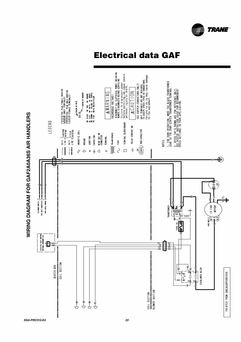
Electrical data GAF
WIR
ING
DIA
GR
AM
FO
R G
AF
2A0A
36S
AIR
HA
ND
LE
RS
34 SSA-PRC010-E4
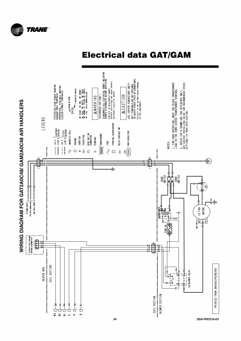
Electrical data GAT/GAM
WIR
ING
DIA
GR
AM
FO
R G
AT
2A0C
48/ G
AM
2A0C
48 A
IR H
AN
DL
ER
S
SSA-PRC010-E4 35
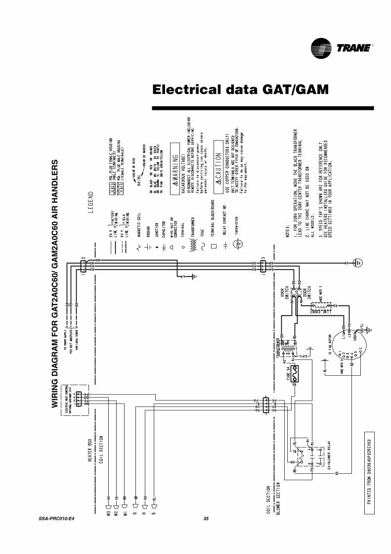
Electrical data GAT/GAM
WIR
ING
DIA
GR
AM
FO
R G
AT
2A0C
60/ G
AM
2A0C
60 A
IR H
AN
DL
ER
S

36 SSA-PRC010-E4
Wiring 2TTB

SSA-PRC010-E4 37
Wiring 2TTB
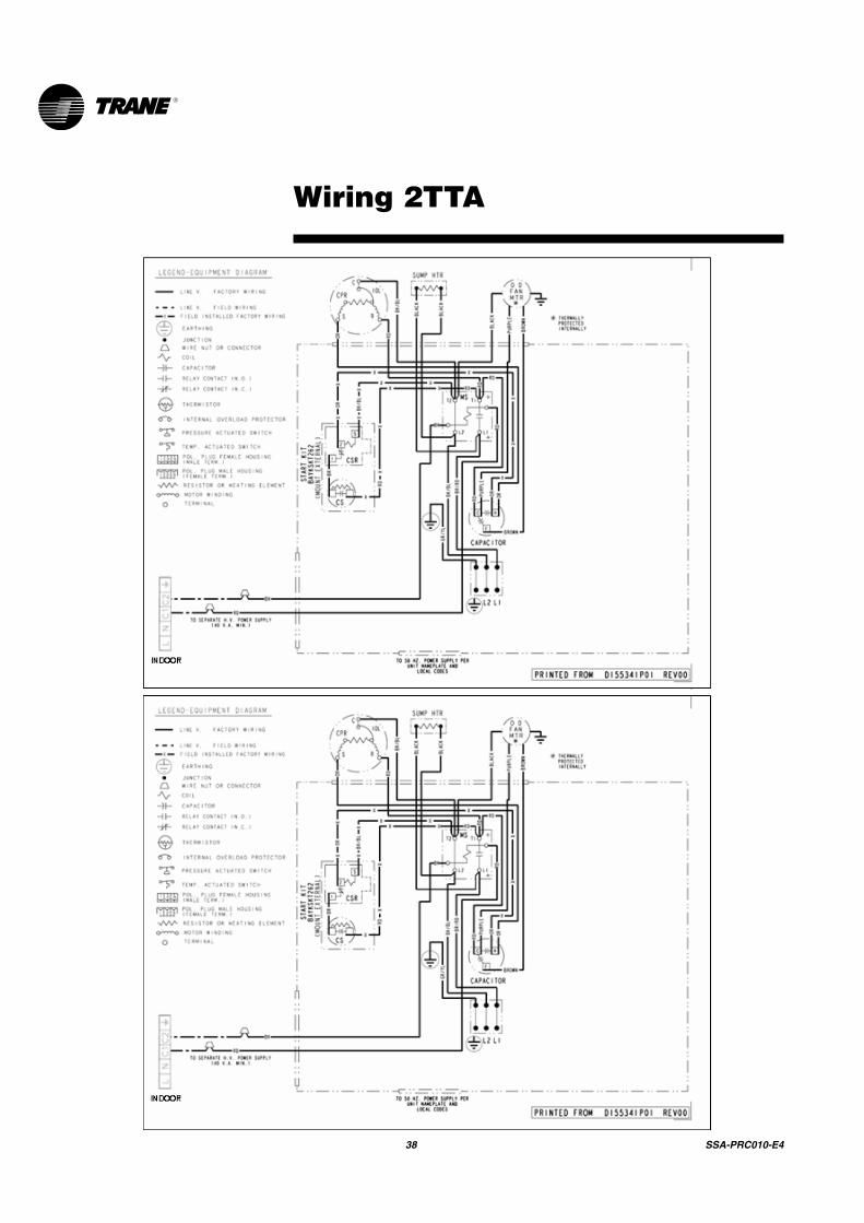
38 SSA-PRC010-E4
Wiring 2TTA

SSA-PRC010-E4 39
Wiring 2TTA

40 SSA-PRC010-E4
Wiring 2TTA
SSA-PRC010-E4 41
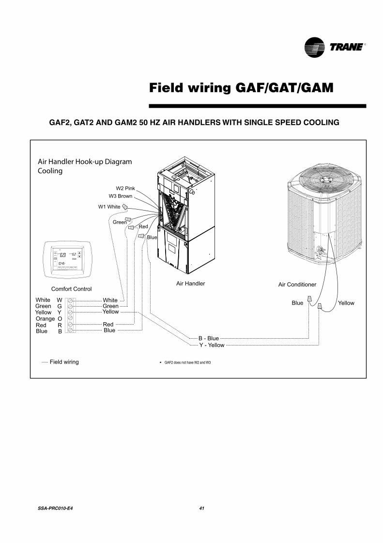
Field wiring GAF/GAT/GAM
GAF2, GAT2 AND GAM2 50 HZ AIR HANDLERS WITH SINGLE SPEED COOLING
Air Handler Hook-up DiagramCooling
Red
YellowGreenWhite
Blue
YellowGreenWhite
Blue BB - Blue
BlueWGY
Y - Yellow
Yellow
RRedOOrange
Comfort ControlAir Handler Air Conditioner
Field wiring
Red
Blue
Green
W2 PinkW3 Brown
W1 White
• GAF2 does not have W2 and W3
42 SSA-PRC010-E4
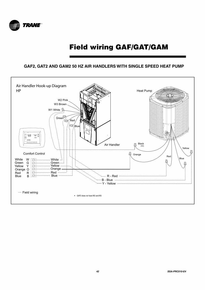
Field wiring GAF/GAT/GAM
GAF2, GAT2 AND GAM2 50 HZ AIR HANDLERS WITH SINGLE SPEED HEAT PUMP
Air Handler Hook-up DiagramHP
Red
YellowGreenWhite
Blue
OrangeYellowGreenWhite
Blue BB - Blue
R - Red
WGY
Y - Yellow
RRedOOrange
Comfort Control
Air Handler
Field wiring
Yellow
Blue
Black(X2)
RedOrange
Heat Pump
Red
Blue
Green
W2 PinkW3 Brown
W1 White
• GAF2 does not have W2 and W3

SSA-PRC010-E4 43
Convertibility GAF/GAT/GAM
* Note: No internal modifications required for any position. Badge rotation will keep brand in correct position
Upflow Condensate Drains
Refrigerant Connections
Upflow Configuration
Low Voltage Connections inside unit
Air
flo
w
Horizontal Right Configuration
Refrigerant Connections
Horizontal Left Condensate Drains
Low Voltage Connections inside unit
Refrigerant Connections
Horizontal Left ConfigurationLow Voltage Connections inside unit
Horizontal Right Condensate Drains
Airflow Airflow
44 SSA-PRC010-E4
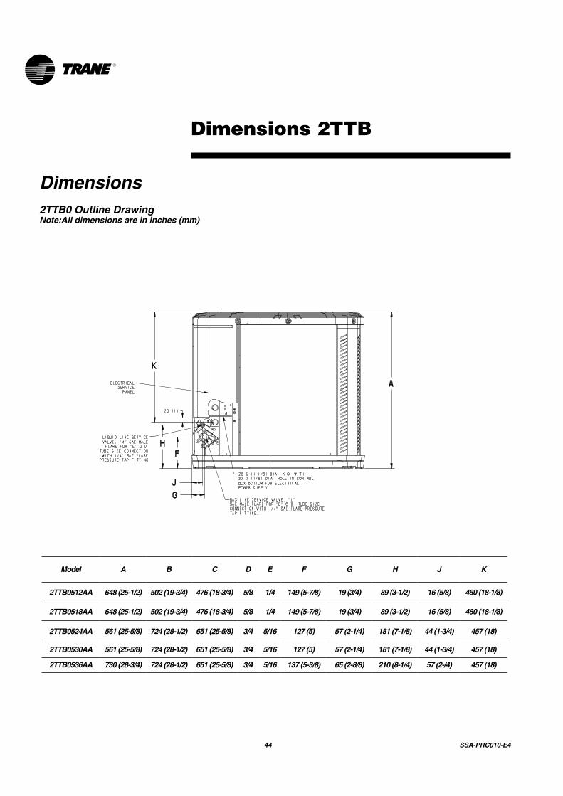
Dimensions 2TTB
Dimensions2TTB0 Outline DrawingNote:All dimensions are in inches (mm)
Model A B C D E F G H J K
2TTB0512AA 648 (25-1/2) 502 (19-3/4) 476 (18-3/4) 5/8 1/4 149 (5-7/8) 19 (3/4) 89 (3-1/2) 16 (5/8) 460 (18-1/8)
2TTB0518AA 648 (25-1/2) 502 (19-3/4) 476 (18-3/4) 5/8 1/4 149 (5-7/8) 19 (3/4) 89 (3-1/2) 16 (5/8) 460 (18-1/8)
2TTB0524AA 561 (25-5/8) 724 (28-1/2) 651 (25-5/8) 3/4 5/16 127 (5) 57 (2-1/4) 181 (7-1/8) 44 (1-3/4) 457 (18)
2TTB0530AA 561 (25-5/8) 724 (28-1/2) 651 (25-5/8) 3/4 5/16 127 (5) 57 (2-1/4) 181 (7-1/8) 44 (1-3/4) 457 (18)
2TTB0536AA 730 (28-3/4) 724 (28-1/2) 651 (25-5/8) 3/4 5/16 137 (5-3/8) 65 (2-8/8) 210 (8-1/4) 57 (2-/4) 457 (18)

SSA-PRC010-E4 45
Dimensions 2TTA
2TTA0 Outline DrawingNote:All dimensions are in inches (mm)
Model A B C D E F G H J K
2TTA0040AD 730 (28-3/4) 724 (28-1/2) 651 (25-5/8) 1-1/8 3/8 137 (5-3/8) 65 (2-8/8) 210 (8-1/4) 57 (2-/4) 457 (18)
2TTA0050AD 832 (32-3/4) 829 (32-5/8) 756 (29-3/4) 1-1/8 3/8 143 (5-5/8) 92 (3-5/8) 210 (8-1/4) 79 (3-1/8) 508 (20)
2TTA0060AD 1045 (41-1/8) 946 (37-1/4) 870 (34-1/4) 1-1/8 3/8 152 (6) 98 (3-7/8) 219 (8-5/8) 86 (3-3/8) 508 (20)
46 SSA-PRC010-E4
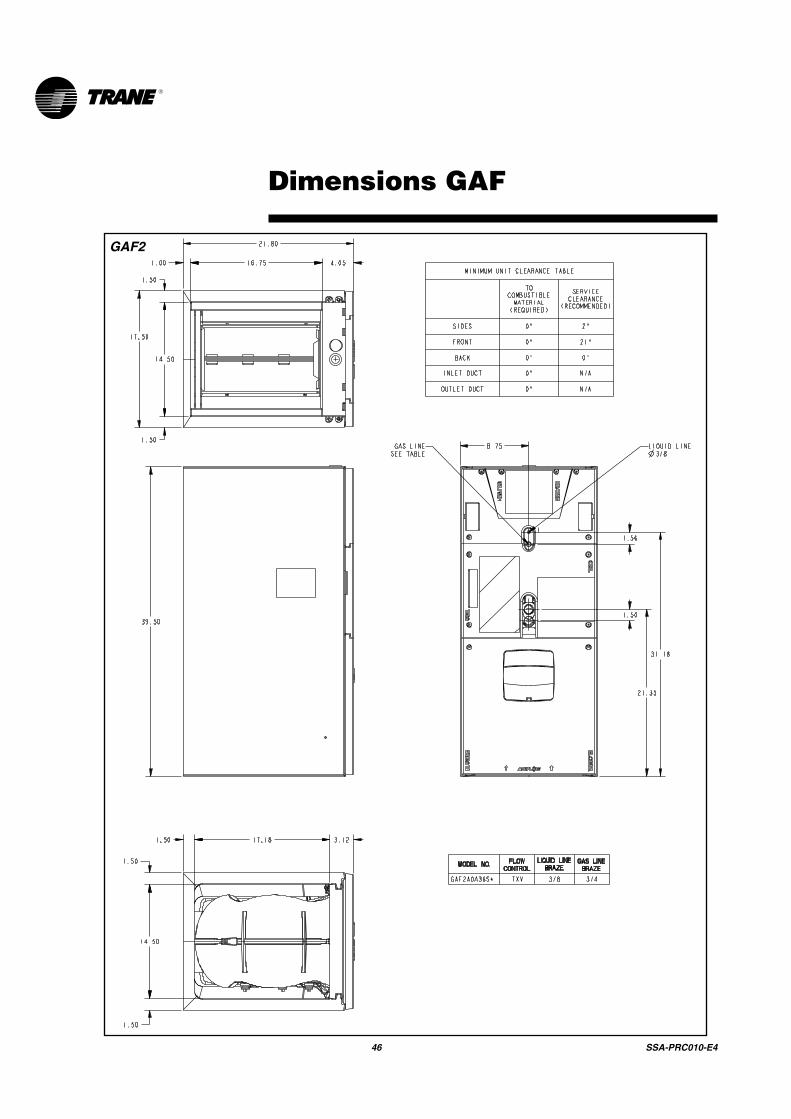
Dimensions GAF
GAF2

SSA-PRC010-E4 47
Dimensions GAF
H
W
D
GAF2 AIR HANDLERS ARE ALL ONE PIECE CABINETS.
Model Number
H x W x D in.
Unit Net Weight
lbs.
GAF2A0A36S3ASA 39 x 17.5 x 22 112

48 SSA-PRC010-E4
Dimensions GAT/GAM
GAT2/GAM2
MODEL NO. ABC DE FH FLOW CONTROL
GAS LINE BRAZE
GAT2A0C48S4ASA 56.9 46.7 20.5 23.5 20.5 10.3 24.2 TXV 7/8
GAT2A0C60S5ASA 61.7 51.5 20.5 23.5 20.5 10.3 27.0 TXV 7/8
GAM2A0C48S4ASBA 56.9 46.7 20.5 23.5 20.5 10.3 24.2 TXV 7/8
GAM2A0C60S5ASBA 51.5 20.5 23.5 20.5 10.3 27.0 TXV 7/861.7

SSA-PRC010-E4 49
Dimensions GAT/GAM
D
H
W
GAT2/GAM2 AIR HANDLERS ARE ALL TWO PIECE CABINETS.
Model Number
H x D x W in.
**Blower Compartment
in.
Unit Net Weight
lbs.
GAT2A0C48S4ASA 56.9 x 23.5 x 21.82 2 143
GAT2A0C60S5ASA 61.7 x 23.5 x 21.82 2 159GAM2A0C48S4ASA 56.9 x 23.5 x 21.82 2 143
GAM2A0C60S5ASA 61.7 x 23.5 x 21.82 2 159
** Subtract from total height to get Coil and Heater compartment height.

Mechanical Specifications 2TTA/2TTB
GeneralThe unit shall be fully charged from the factory for matched indoor section and up to 15 feet of piping. This unit must be designed to operate at outdoor ambient temperatures as high as 115°F. Cooling capacities shall be matched with a wide selection of air handlers. Exterior must be designed for outdoor application.
CasingUnit casing is constructed of heavy gauge, galvanized steel and painted with a weather-resistant powder paint.Corrosion and weatherproof CMBP-G30 Duratuff™ base.(2TTB/2TTA)
Refrigerant ControlsRefrigeration system controls include condenser fan and compressor contactor. High and low pressure controls are inherent to the compressor. Another standard feature is the liquid line dryer.
CompressorThe Climatuff® compressor features internal over temperature and pressure protector, total dipped hermetic motor and thermostatically controlled sump heater. Other features include: roto lock suction and discharge refrigerationconnections, centrifugal oil pump, and low vibration and noise.
Condenser CoilThe Spine Fin™ coil shall be continuously wrapped, corrosion resistant all aluminum with minimum brazed joints. This coil is 3/8 inch O.D. seamless aluminumglued to a continuous aluminum fin. Coils are lab tested to withstand 2,000 pounds of pressure per square inch. The outdoor coil provides low airflow resistance and efficient heat transfer. The coil is protected on all four sides by louvered panels and has a 10 year limited warranty.Low Ambient CoolingAs manufactured, this unit has a cooling capability to 55°F. The addition of an evaporator defrost control permits operation to 40°F. The addition of an evaporator defrost control with TXV permits low ambient cooling to 30°F.
Accessories
Thermostats — Heating/Cooling (manual and automatic changeover). Sub-base to match thermostat and locking thermostat cover.
Evaporator Defrost Control — See Low Ambient Cooling.
Outdoor Thermostat — Supplemental heat outdoor ambient lockout from 46 to –10°F.

Trane optimizes the performance of homes and buildings around the world. A business of Ingersoll Rand, the leader in creating and sustaining safe, comfortable and energy efficient environments, Trane offers a broad portfolio of advanced controls and HVAC systems, comprehensive building services, and parts. For more information, visit www.Trane.com.
Trane has a policy of continuous product and product data improvement and reserves the right to change design and specifications without notice.
© 2013 Trane All rights reservedSSA-PRC010-E4 March 2014
We are committed to usingenvironmentally conscious printpractices that reduce waste.