Embed Size (px)
Citation preview

1 © Agrowtek Inc. | www.agrowtek.com
Technology to Help You GrowAGROWtEK
Hydroponics Sensor Transmitter & Data LoggerTemperature, pH, EC (+ORP/DO)
ContentsDimensions 2Installation Instructions 2pH & ORP Probe Preparation 3Mounting the Transmitter 4DIN Rail Mounting Kit 4Connecting Sensor Probes 4Ground O�set Prevention 5
Connection to ADi Pump 5LCD Menu Operation Instructions 6High / Low History 6Graphing 6Main Menu 7Alarms Menu 7Alarms Con�guration 7Alarm Buzzer 8Calibration Menu 8Clear Calibration 8Temperature Calibration 9pH Calibration 9Conductivity Calibration 10O.R.P. Calibration 10D.O. Calibration 11D.O. Saturation Chart 12Advanced Calibration 13Analog Output Calibration 13Setup Menu 14
Time / Date 14Units 14Logging Interval 15COMM Mode 16Device Address 16Manufacturing Info 16Display Back Light Timer 17
Connection to 4-20mA Outputs 17Connection to USB AgrowLINK 18Firmware Update 18
Connection to MODBUS RTU 19HX8 8-Port Hubs 19Serial Speed & Format 19Supported Commands 20Register Types 20Sensor Value Registers 20Calibration Registers 20MODBUS Register Map 21
Maintenance 22Probe Cleaning 22pH Probe Reconditioning 22
Technical Information 23Speci�cations 23Storage and Disposal 23
Warranty 23
Shown with optional sensor probes
INSTRUCTION MANUAL
SXH / SXH+

2 © Agrowtek Inc. | www.agrowtek.com
5.0
Technology to Help You GrowAGROWtEK
U.S.A.
MADE IN
© Arowtek Inc. | www.agrowtek.com
GrowNETLink PortMODBUS
TM Digital Water SensorLogger & Controller
TEMPERATURE CONDUCTIVITYpH O.R.P. / D.O.
GrowControlTM
pHProbe
o.r.p./d.o.Probe
Temp Probe | EC Probe
red blk wht | clr red blk
BNC pH Probe
(optional) BNC ORP/DO Probe
Temperature & ConductivityProbes
GrowNET PortRS485 MODBUS
Color LCD DisplayButton Interface(optional)
12-24V DC Power Input Jackor MINI-DIN6 Analog Connector (shwon)
Dimensions
Do NOT connect the GrowNET port to Ethernet networks.
Technology to Help You GrowAGROWtEK
U.S.A.
MADE IN
© Arowtek Inc. | www.agrowtek.com
GrowNETLink PortMODBUS
TM Digital Water SensorLogger & Controller
TEMPERATURE CONDUCTIVITYpH O.R.P. / D.O.
GrowControlTM
pHProbe
o.r.p./d.o.Probe
Temp Probe | EC Probe
red blk wht | clr red blk
FROMSAMPLE
PUMP
WATERTANK
RETURN
PBX-310Sensor Manifold
1” NPTConnections
(optional)
Installation InstructionsInstall with the connections facing down to reduce the risk of water permeating the enclosure.
Avoid locations with dripping water or heavy splash risk; the transmitter is best kept dry for longest life and highest accuracy.
A probe manifold with recirulating pump (3-30gpm) is recommended for best sensor accuracy.
IMPORTANT NOTE: For �ow rates above 5 gpm, ensure probe tips are raised out of the �ow path to prevent turbulence altering the sensor readings.

3 © Agrowtek Inc. | www.agrowtek.com
pH & ORP Probe PreparationProbe Shipping & Storage
pH & ORP probes are shipped in a plastic bottle containing a solution of pH 4 bu�er and potassium chloride. The electrode should remain in the bottle until it is used.
If the electrode is used infrequently, the bottle and its solution should be saved and the electrode stored in it. If the solution in the soaker bottle is missing, �ll the bottle with pH 4 bu�er.
Take out electrode by loosening plastic top on bottle counterclockwise and pulling electrode out. Slide cap and O-ring o� electrode and save.
BLACK O-RING
INSIDE TOP
Black O-ring inside
Air Bubble
During shipment the air bubble in the electrode’s stem may move into the bulb area.
If bubbles are seen in the bulb area, hold the electrode by its top cap and shake while pointed downward.
ELB BUB RIAAIR BUBBLE
Installation/Operation Angle
pH & ORP sensor probes must be installed in an above-horizontal position with the probe tip facing downward to prevent the air bubble from entering the the bulb area.
10° min.

4 © Agrowtek Inc. | www.agrowtek.com
pH and ORP or DO sensors are equipped with “BNC” style connectors which push on and then turn 1/4 rota-tion CW to lock them in place. Temperature and EC probes have a screw terminal block; make the connec-tions according to the label on the transmitter. The terminal block may be removed for easier wire installa-tion or for service.
Connecting Sensor Probes
pHProbe
o.r.p./d.o.Probe
Temp Probe | EC Probe
red blk wht | clr red blk
Wall mounting tabs are provided for installing against a vertical wall surface.
1. Measure out the hole locations per the dimensions, or mark the holes using the transmitter as a template.2. Drill holes and install anchors (if required, not included.) Keep the transmitter away from dust during work.3. Install the transmitter to the wall surface using appropriate screws.
Mounting the Transmitter
A DIN rail mounting kit installs onto the mounting �anges with the provided hard-ware for mounting the device on a standard DIN rail.
1. Screw the DIN rail brackets onto the �anges using the provided screws.2. Snap the transmitter into place on a DIN rail.3. Use the latches on the DIN brackets to release the transmitter from the DIN rail.
DIN Rail Mounting Kit
pH & ORP probes must remain wet to avoid damage. Do not allow probe tips to dry.
NOTE:1. Some EC probes may not have a “clear” wire and may only have a red and black wire.2. Ground o�set wire may be connected to the EC “CLR” terminal (see following page.)

5 © Agrowtek Inc. | www.agrowtek.com
Agrowtek Cross-Over
Adapter
cat5 cat5
Connection to ADi PumpA direct-link connection between a SXHM sensor and ADi pump requires Agrowtek’s cross-over adapter.
IMPORTANT! ONLY use cross-over adapters provided by Agrowtek. Do not use other cross-over adapters or cross-over cables unless they are constructed exactly as diagramed on the cross-over diagram. Incorrect cross-over adapters or cables can cause damage to the equipment.
12Vdc 1APower Supply
Technology to Help You GrowAGROWtEK
U.S.A.
MADE IN
© Arowtek Inc. | www.agrowtek.com
GrowNET
Link PortMODBUS
TM Digital Water Sensor
Logger & Controller
TEMPERATURECONDUCTIVITY
pHO.R.P. / D.O.
GrowControlTM
pH
Probe
o.r.p./d.o.
Probe
Temp Probe | EC Probe
red blk wht | clr red blk
Ground O�set Prevention
PROBECLAMP
TEMPERATUREPROBE
GROUNDOFFSETWIRE
Sensor measurements are sensitive to di�erences in ground potential. If sensor readings are unstable or change readings in the system vs. in an isolated cup, then there may be a ground potential problem. To pre-vent errors in readings from ground potential o�set, install a ground o�set wire.
Note:Temperature sensors with 4-wires have a green wire for
ground o�set and the external wire is not required.
Connect the ground o�set wire from the “CLR” terminal to the temperature probe with probe clamp.

6 © Agrowtek Inc. | www.agrowtek.com
SXHM models with the optional 3-button/LCD display interface may be used for stand-alone monitoring applications or as part of a control solution.
Connect to Agrowtek’s GrowControl facility control systems, or directly to Agrowtek’s AgrowDose pumps for automatic nutrient and pH control.
LCD Menu Operation Instructions
Simple minimum and maximum recorded values are stored until the user resets the values to the current readings. To view the minimum and maximum values since the last reset, press the button labeled H/L.
To clear the min/max history, press the RST button to reset. The min and max values will all be set to the current readings and will update with higher or lower readings as they occur.
High / Low HistoryGPH MNUH/L
72.06.101550600
°FpHuS
mV
The main screen displays the real-time sensor readings from the attached sensors. Each button is labeled at the bottom of the display to describe it’s function on the current screen or menu.
RSTEXIT
72.04.85657480
°FpH
mV
68.44.21551404
HIGHLOW
uS
Technology to Help You GrowAGROWtEK
U.S.A.
MADE IN
© Arowtek Inc. | www.agrowtek.com
GrowNETLink PortMODBUS
TM Digital Water SensorLogger & Controller
TEMPERATURE CONDUCTIVITYpH O.R.P. / D.O.
GrowControlTM
pHProbe
o.r.p./d.o.Probe
Temp Probe | EC Probe
red blk wht | clr red blk
GPH MNUH/L
72.06.21550
°FpHuS
The display can graph the most recent 120 data points from the sensor’s internal data point memory. With the default logging interval of 60 seconds, the graph displays the last two hours of data.
The sensor value is plotted in green. Tem-perature, if overlaid on the plot, is red. Alarm levels as set by the user are plotted in yellow. Pressing the RFH button refreshes the data and replots the graph.
Graphing
RFH BCK
PH
High Alarm
Low Alarm
Temperature
Sensor Data (pH)
GPH MNUH/L
72.06.101550600
°FpHuS
mV
DWN ENTUP
BACKTEMPERATUREPHCOND
GRAPH
ORP

7 © Agrowtek Inc. | www.agrowtek.com
The main menu is how the alarms are set, sensors are calibrated and general settings such as time, date and units are con�gured.
If a dosing pump is directly connected to the SXHM GrowNET port, the pump settings are also accessed by the main menu.
Use the UP or DWN buttons to navigate the menu.
Use the ENT button to enter a selection.
Main MenuGPH MNUH/L
72.06.101550600
°FpHuS
mV
High and low alarm set points may be con�gured for each sensor value to activate an internal buzzer or send alerts with the optional wi� module.
The out-of-range value will be displayed in red to indicate the cause for the alarm.
Additionally, alarm limits are plotted on the graphs to indicate values are within the desired range.
Alarms Menu
DWN ENTUP
EXITALARMSCALIBRATIONSETUPPUMPS
MENU
GPH MNUH/L
72.06.101550600
°FpHuS
mV
DWN ENTUP
EXITALARMSCALIBRATIONSETUPPUMPS
MENU
DWN ENTUP
EXITALARMSCALIBRATIONSETUP
MENU
DWN ENTUP
BACK+0.1-0.1
SET LOW
0.0°F
1. Select ALARMS from the main menu.
3. Select the setting to adjust.
2. Select a sensor to con�gure set points.
4. Adjust to the desired value. Hold UP or DWN to jog the value.
DWN ENTUP
BACKLOW: 0.0HIGH: 0.0ALARM: OFF
ALARM
DWN ENTUP
BACKTEMPERATUREPHCOND
ALARMS
ORP
Alarms Con�guration
GPH MNUH/L
72.05.141550600
°FpHuS
mV

8 © Agrowtek Inc. | www.agrowtek.com
To disable the alarm buzzer, set the alarm to OFF.
Calibration Menu
Calibration can be performed for each sensor with the LCD interface using either standard calibration wizards, or advanced manual calibration methods for non-stan-dard calibration solutions.
The date of the last calibration for each sensor is stored in memory and displayed at the start of each calibration wizard.
GPH MNUH/L
72.06.101550600
°FpHuS
mV
DWN ENTUP
EXITALARMSCALIBRATIONSETUPPUMPS
MENU
DWN ENTUP
EXITALARMSCALIBRATIONSETUP
MENU
DWN ENTUP
BACKTEMPERATUREPHCOND
CALIBRATION
CLEAR ALL
DWN ENTUP
BACKLOW: 0.0HIGH: 0.0ALARM: OFF
ALARM
1. Select ALARM: OFF
DWN ENTUP
BACKSET ONSET OFF
SET ALARM
OFF
2. Select SET ON then press BACK to exit.
Alarm Buzzer
1. Select CLEAR ALL from the calibration menu.
2. Press YES to restore factory calibration.
GPH MNUH/L
72.06.101550600
°FpHuS
mV
DWN ENTUP
EXITALARMSCALIBRATIONSETUPPUMPS
MENU
Clear Calibration
Calibration can be restored to factory defaults by selecting CLEAR ALL.
NOYES
RESTORE TOFACTORY
CALIBRATION?
DWN ENTUP
BACKTIME/DATEUNITSLOG INTERVAL
SETUP
NEXT
DWN ENTUP
BACKTEMPERATUREPHCOND
CALIBRATION
CLEAR ALL

9 © Agrowtek Inc. | www.agrowtek.com
pH calibration is a two-point process requiring both pH 7 and pH 4.01 calibration solutions. The temperature probe must be inserted into the calibration solution at the same time as the pH probe.
GPH MNUH/L
72.06.101550600
°FpHuS
mV
DWN ENTUP
EXITALARMSCALIBRATIONSETUPPUMPS
MENU
pH Calibration
2. Follow the instruc-tions then press NEXT.
4. Clean the probes with DI/RO and change calibration solution.
3. When the reading is stable, press NEXT.
5. When the reading is stable, press DONE to calibrate pH 4.01 and �nish calibration.
NEXTEXIT
PHLAST CALIBRATION
10/19/2017
STEP 1:PUT TEMPERATUREAND PH PROBE INPH7 SOLUTION.
NEXTEXIT
PH
WAIT FOR READINGTO STABILIZE THENPRESS NEXT.
7.12 pH
NEXTEXIT
PH
STEP 2:PUT TEMPERATUREAND PH PROBE INPH4.01 SOLUTION.
7.00 pH
DNEEXIT
PH
WAIT FOR READINGTO STABILIZE THENPRESS DONE.
4.14 pH
pH 7 Calibration Solution
pH 4.01 Calibra-tion Solution
1. Select CALIBRATE from calibration menu.
DWN ENTUP
BACKCALIBRATEADVANCED
CALIBRATION DWN ENTUP
BACKTEMPERATUREPHCOND
CALIBRATION
DO
1. Select CALIBRATE from calibration menu.
3. Adjust to the desired value. Hold ENT to jog the value by 10x.
2. Press NEXT to con-tinue.
4. Con�rm the new reading or press NO.
DWN ENTUP
BACK+0.1-0.1
OFFSET
72.2°FNEXTEXIT
TEMPERATURELAST CALIBRATION
10/19/2017
PRESS NEXT TOADJUSTTEMPERATUREREADING.
NOYES
CONFIRM?
72.2 °F
68.1 °FOLD
NEW
DWN ENTUP
BACKCALIBRATEADVANCED
CALIBRATION
GPH MNUH/L
72.06.101550600
°FpHuS
mV
DWN ENTUP
EXITALARMSCALIBRATIONSETUPPUMPS
MENU
Temperature Calibration
DWN ENTUP
BACKTEMPERATUREPHCOND
CALIBRATION
DO
10 © Agrowtek Inc. | www.agrowtek.com
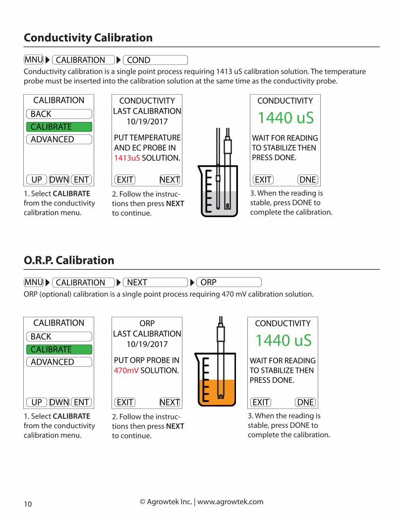
1. Select CALIBRATE from the conductivity calibration menu.
3. When the reading is stable, press DONE to complete the calibration.
2. Follow the instruc-tions then press NEXT to continue.
DWN ENTUP
BACKCALIBRATEADVANCED
CALIBRATION
GPH MNUH/L
72.06.101550600
°FpHuS
mV
DWN ENTUP
EXITALARMSCALIBRATIONSETUPPUMPS
MENU
Conductivity Calibration
Conductivity calibration is a single point process requiring 1413 uS calibration solution. The temperature probe must be inserted into the calibration solution at the same time as the conductivity probe.
NEXTEXIT
CONDUCTIVITYLAST CALIBRATION
10/19/2017
PUT TEMPERATUREAND EC PROBE IN1413uS SOLUTION.
1. Select CALIBRATE from the conductivity calibration menu.
3. When the reading is stable, press DONE to complete the calibration.
2. Follow the instruc-tions then press NEXT to continue.
DWN ENTUP
BACKCALIBRATEADVANCED
CALIBRATION
GPH MNUH/L
72.06.101550600
°FpHuS
mV
DWN ENTUP
EXITALARMSCALIBRATIONSETUPPUMPS
MENU
O.R.P. Calibration
ORP (optional) calibration is a single point process requiring 470 mV calibration solution.
NEXTEXIT
ORPLAST CALIBRATION
10/19/2017
PUT ORP PROBE IN470mV SOLUTION.
DNEEXIT
CONDUCTIVITY
WAIT FOR READINGTO STABILIZE THENPRESS DONE.
1440 uS
DWN ENTUP
BACKTIME/DATEUNITSLOG INTERVAL
SETUP
NEXT
DNEEXIT
CONDUCTIVITY
WAIT FOR READINGTO STABILIZE THENPRESS DONE.
1440 uS
DWN ENTUP
BACKTEMPERATUREPHCOND
CALIBRATION
DO
DWN ENTUP
BACKORPCLEAR ALL
CALIBRATION

11 © Agrowtek Inc. | www.agrowtek.com
1. Select CALIBRATE from the conductivity calibration menu.
3. When the reading is stable, press DONE to complete the calibration.
2. Follow the instruc-tions then press NEXT to continue.
DWN ENTUP
BACKCALIBRATEADVANCED
CALIBRATION
GPH MNUH/L
72.06.101550600
°FpHuS
mV
DWN ENTUP
EXITALARMSCALIBRATIONSETUPPUMPS
MENU
D.O. Calibration
DO Calibration is a two-point process requiring zero-oxygen solution and either air or saturated solution.
NEXTEXIT
DOLAST CALIBRATION
10/19/2017
PUT DO PROBE INZERO OXYGENSOLUTION.
NXTEXIT
DO
WAIT FOR READINGTO STABILIZE THENPRESS NEXT.
1.2 mg/L
DWN ENTUP
BACKTIME/DATEUNITSLOG INTERVAL
SETUP
NEXT
DWN ENTUP
BACKTEMPERATUREPHCOND
CALIBRATION
DO
5. When the reading is stable, press NEXT to adjust the saturation calibration.
4. Follow the instruc-tions then press NEXT to continue.
NEXTEXIT
DO
PUT DO PROBE INAIR.
NXTEXIT
DO
WAIT FOR READINGTO STABILIZE THENPRESS NEXT.
12.7 mg/L
6. Adjust the saturation value according to the chart on the following page.
DWN ENTUP
DONE+0.1-0.1
DO
11.5 mg/L

12 © Agrowtek Inc. | www.agrowtek.com
D.O. Saturation ChartThe saturation concentation must be calculated manually using the standard reference chart below. Use the reference value from the chart to determine the calibration for the probe at 100% saturation.
Oxygen Saturation Table (in mg/l or ppm)(assume elevation at sea level and 100% water saturation of air above sample)
) ppm/1000tpp( ytinilaSpmeT
(°C) 0 2 4 6 8 10 12 14 16 18 20 22 24 26 28 30 32 340 14.6 14.4 14.2 14.0 13.8 13.6 13.4 13.3 13.1 12.9 12.7 12.6 12.4 12.2 12.0 11.9 11.7 11.61 14.2 14.0 13.8 13.6 13.4 13.3 13.1 12.9 12.7 12.6 12.4 12.2 12.1 11.9 11.7 11.6 11.4 11.32 13.8 13.6 13.4 13.3 13.1 12.9 12.7 12.6 12.4 12.2 12.1 11.9 11.7 11.6 11.4 11.3 11.1 11.03 13.4 13.3 13.1 12.9 12.7 12.6 12.4 12.2 12.1 11.9 11.8 11.6 11.4 11.3 11.1 11.0 10.8 10.74 13.1 12.9 12.7 12.6 12.4 12.2 12.1 11.9 11.8 11.6 11.5 11.3 11.2 11.0 10.9 10.7 10.6 10.45 12.7 12.6 12.4 12.3 12.1 11.9 11.8 11.6 11.5 11.3 11.2 11.0 10.9 10.7 10.6 10.5 10.3 10.26 12.4 12.3 12.1 11.9 11.8 11.6 11.5 11.3 11.2 11.0 10.9 10.8 10.6 10.5 10.3 10.2 10.1 9.97 12.1 12.0 11.8 11.7 11.5 11.4 11.2 11.1 10.9 10.8 10.6 10.5 10.4 10.2 10.1 10.0 9.8 9.78 11.8 11.7 11.5 11.4 11.2 11.1 10.9 10.8 10.7 10.5 10.4 10.3 10.1 10.0 9.9 9.7 9.6 9.59 11.5 11.4 11.2 11.1 11.0 10.8 10.7 10.5 10.4 10.3 10.2 10.0 9.9 9.8 9.6 9.5 9.4 9.3
10 11.3 11.1 11.0 10.8 10.7 10.6 10.4 10.3 10.2 10.0 9.9 9.8 9.7 9.6 9.4 9.3 9.2 9.111 11.0 10.9 10.7 10.6 10.5 10.3 10.2 10.1 9.9 9.8 9.7 9.6 9.5 9.3 9.2 9.1 9.0 8.912 10.8 10.6 10.5 10.4 10.2 10.1 10.0 9.9 9.7 9.6 9.5 9.4 9.3 9.1 9.0 8.9 8.8 8.713 10.5 10.4 10.3 10.1 10.0 9.9 9.8 9.6 9.5 9.4 9.3 9.2 9.1 8.9 8.8 8.7 8.6 8.514 10.3 10.2 10.0 9.9 9.8 9.7 9.6 9.4 9.3 9.2 9.1 9.0 8.9 8.8 8.7 8.5 8.4 8.315 10.1 9.9 9.8 9.7 9.6 9.5 9.3 9.2 9.1 9.0 8.9 8.8 8.7 8.6 8.5 8.4 8.3 8.216 9.8 9.7 9.6 9.5 9.4 9.3 9.2 9.0 8.9 8.8 8.7 8.6 8.5 8.4 8.3 8.2 8.1 8.017 9.6 9.5 9.4 9.3 9.2 9.1 9.0 8.9 8.8 8.6 8.5 8.4 8.3 8.2 8.1 8.0 7.9 7.918 9.4 9.3 9.2 9.1 9.0 8.9 8.8 8.7 8.6 8.5 8.4 8.3 8.2 8.1 8.0 7.9 7.8 7.719 9.3 9.1 9.0 8.9 8.8 8.7 8.6 8.5 8.4 8.3 8.2 8.1 8.0 7.9 7.8 7.7 7.6 7.620 9.1 9.0 8.9 8.8 8.6 8.5 8.4 8.3 8.2 8.2 8.1 8.0 7.9 7.8 7.7 7.6 7.5 7.421 8.9 8.8 8.7 8.6 8.5 8.4 8.3 8.2 8.1 8.0 7.9 7.8 7.7 7.6 7.5 7.5 7.4 7.322 8.7 8.6 8.5 8.4 8.3 8.2 8.1 8.0 7.9 7.9 7.8 7.7 7.6 7.5 7.4 7.3 7.2 7.223 8.6 8.5 8.4 8.3 8.2 8.1 8.0 7.9 7.8 7.7 7.6 7.5 7.4 7.4 7.3 7.2 7.1 7.024 8.4 8.3 8.2 8.1 8.0 7.9 7.8 7.7 7.7 7.6 7.5 7.4 7.3 7.2 7.1 7.1 7.0 6.925 8.2 8.1 8.1 8.0 7.9 7.8 7.7 7.6 7.5 7.4 7.3 7.3 7.2 7.1 7.0 6.9 6.9 6.826 8.1 8.0 7.9 7.8 7.7 7.6 7.6 7.5 7.4 7.3 7.2 7.1 7.1 7.0 6.9 6.8 6.7 6.727 7.9 7.9 7.8 7.7 7.6 7.5 7.4 7.3 7.3 7.2 7.1 7.0 6.9 6.9 6.8 6.7 6.6 6.628 7.8 7.7 7.6 7.5 7.5 7.4 7.3 7.2 7.1 7.1 7.0 6.9 6.8 6.7 6.7 6.6 6.5 6.529 7.7 7.6 7.5 7.4 7.3 7.3 7.2 7.1 7.0 6.9 6.9 6.8 6.7 6.6 6.6 6.5 6.4 6.330 7.5 7.4 7.4 7.3 7.2 7.1 7.1 7.0 6.9 6.8 6.7 6.7 6.6 6.5 6.5 6.4 6.3 6.2
This table uses the formula % saturation = = EXP(-173.4292+249.6339*100/T+143.3483*LN(+T/100)-21.8492*T/100+S*(-0.033096+0.014259*T/100-0.0017*(T/100)^2))*1.4276
where S is salinity in ppt and T is degrees Kelvin (=C+273.15)Formula from Grasshoff, K., et al. (1999), and is generally accurate to 0.1 ppm to empirical studies.
Saturation values are for 760 mm mercury (29.92"). During a high pressure system, saturation values may be 0.4 ppm higher. During a low pressure system, saturation may be 0.5 ppm lower.

13 © Agrowtek Inc. | www.agrowtek.com
Advanced CalibrationSensors values may be manually calibrated to alternate standards using the advance calibration features.
OFFSET calibration applies a linear o�set adjustment to the value. SPAN calibration applies an adjustment to the slope of the sensor value.
Note: pH and conductivty are temperature compensated (ATC) sensors. For accurate calibration, the temperature probe must be in the pH and conduc-tivity calibration standards. Allow all readings to stabilize before performing an o�set or span calibration operation.
PHCAL 7 sets the pH 7 calibration (o�set.) Cal 7 automatically clears span calibration point prior performing pH 7 calibration.
SPAN calibration is performed typically at pH 4.01 or 10.0 (Always perform pH 7 calibration �rst.)
CONDUCTIVITYSET CAL 0 calibrates a dry EC probe if required. (not recommended)SPAN calibration is recommended at 1413uS. If using ppm standards, ensure the display is in the correct units.
DiSSOLVED OXYGEN (D.O.)OFFSET calibration is recommended in zero oxygen solution.SPAN calibration is recommended at a known DO level or in air.
OXIDATION REDUCTION POTENTIAL (O.R.P.)OFFSET is recommended at 270mVSPAN is recommended at 470mV
DWN ENTUP
BACKCALIBRATEADVANCED
CALIBRATION
4-20mA analog outputs may also be calibrated with a positive or negative o�set to compensate for variation in DAC’s/ADC’s. The sensors’ current output may be incrementally increased or decreased in steps of 0.005mA over a range of +/-2mA.
1 O�set bit = 0.005mA, Range = +/-400 bits (+/-2mA)
This calibration procedure is optional and only for use with custom PLC appli-cations.
1. Observe the PLC’s input or data readings.2. Increase or decrease the o�set value to incremenetally adjust the current output until the values match.
Analog Output Calibration
DWN ENTUP
BACK+1-1
ANALOG
-5

14 © Agrowtek Inc. | www.agrowtek.com
The setup menu is where the time and date are set, the units are con�gured, logging interval is adjusted and advanced communications settings are available.
Setup Menu
Sensors include a precision real-time clock with battery back-up for time-stamping the data log information with the time and date. The last calibration for each sensor is also time stamped.
Time / Date
1. Select TIME/DATE from the setup menu.
3. Use NXT to select the value to adjust. Use + to increment the value.
2. Select TIME or DATE to adjust.
4. Use EXT to exit the menu.
DWN ENTUP
BACKTIME/DATEUNITSLOG INTERVAL
SETUP
NEXT
DWN ENTUP
BACKCOMMDEVICE ADDMFG INFO
SETUP
BACKLIGHT
DWN ENTUP
BACKTIME/DATEUNITSLOG INTERVAL
SETUP
NEXT
DWN ENTUP
BACKTIMEDATE
TIME/DATE
+ EXTNXT
DATE
10/202017
+ EXTNXT
TIME
13:37:51
Temperature and Conductivity may be displayed in alternate units.
Select a sensor value to change the default display and working units.
Units
DWN ENTUP
BACKTIME/DATEUNITSLOG INTERVAL
SETUP
NEXTDWN ENTUP
BACKTEMPERATUREEC
UNIT SELECT
GPH MNUH/L
72.06.101550600
°FpHuS
mV
DWN ENTUP
EXITALARMSCALIBRATIONSETUPPUMPS
MENU
GPH MNUH/L
72.06.101550600
°FpHuS
mV
DWN ENTUP
EXITALARMSCALIBRATIONSETUPPUMPS
MENU
DWN ENTUP
BACKTIME/DATEUNITSLOG INTERVAL
SETUP
NEXT
GPH MNUH/L
72.06.101550600
°FpHuS
mV
DWN ENTUP
EXITALARMSCALIBRATIONSETUPPUMPS
MENU
DWN ENTUP
BACKTIME/DATEUNITSLOG INTERVAL
SETUP
NEXT

15 © Agrowtek Inc. | www.agrowtek.com
Adjust the interval for recording data points in the on-board memort. Acceptable values are from 1 - 65535 seconds.
21,600 data points can be stored for each sensor value. The most recent 120 data points are shown on the graphical history.
The entire data history may be downloaded from the sensor to a .csv �le with the LX1 USB AgrowLINK and free software.
Note: 60 second intervals = 15 days of data storage.
Logging Interval
Con�gure temperature units:
1. Select TEMPERATURE from the units menu.
2. Select the desired units and press ENT.
DWN ENTUP
BACKTEMPERATUREEC
UNIT SELECTTemperature may be displayed in °F or °C.
Note: Check alarm settings when converting temperature units.
DWN ENTUP
BACK°C°F
UNIT SELECT
68.0°F
Con�gure conductivity units:
1. Select EC from the units menu.
2. Select the desired units and press ENT.
Conductivity may be displayed in default units of microSiemens (uS) or total dissolved solids in parts per million (ppm.)
The TDS conversion factor used by this meter is 500.
TDSppm = uS x 0.5
DWN ENTUP
BACKTEMPERATUREEC
UNIT SELECT
DWN ENTUP
BACKUSTDS
UNIT SELECT
654 ppm
GPH MNUH/L
72.06.101550600
°FpHuS
mV
DWN ENTUP
EXITALARMSCALIBRATIONSETUPPUMPS
MENU
DWN ENTUP
BACKTIME/DATEUNITSLOG INTERVAL
SETUP
NEXT
1. Select LOG INTERVAL from the setup menu.
2. Adjust the value then select BACK.
DWN ENTUP
BACKTIME/DATEUNITSLOG INTERVAL
SETUP
NEXT
DWN ENTUP
BACK+1-1
LOGGIN INTERVAL
60 SEC

16 © Agrowtek Inc. | www.agrowtek.com
COMM mode speci�es whether the sensor is a normal passive device or “mini-master” device.
NORMAL Use with GrowControl master controller systems or stand-alone and data logging applica-tions.
MINI-MASTER Use with MDX mini-dosing system. (GrowNET cross-over adapter required.)
COMM ModeGPH MNUH/L
72.06.101550600
°FpHuS
mV
DWN ENTUP
EXITALARMSCALIBRATIONSETUPPUMPS
MENU
DWN ENTUP
BACKTIME/DATEUNITSLOG INTERVAL
SETUP
NEXT
DWN ENTUP
BACKCOMMDEVICE ADDMFG INFO
SETUP
BACKLIGHT
1. Select COMM from the setup menu.
2. Select a mode and press ENT.
Sensors are digitally addressable from 1-249 and will be assigned an address automatically by Agrowtek’s control systems, or can be con�gured manually for MODBUS applications via the menu.
NOTE: All of Agrowtek’s devices use address 254 as a broadcast address.
Device AddressGPH MNUH/L
72.06.101550600
°FpHuS
mV
DWN ENTUP
EXITALARMSCALIBRATIONSETUPPUMPS
MENU
DWN ENTUP
BACKTIME/DATEUNITSLOG INTERVAL
SETUP
NEXT
DWN ENTUP
BACKCOMMDEVICE ADDMFG INFO
SETUP
BACKLIGHT
1. Select DEVICE ADD from the setup menu.
2. Adjust the value then select BACK.
DWN ENTUP
BACKCOMMDEVICE ADDMFG INFO
SETUP
BACKLIGHT
DWN ENTUP
BACK+1-1
DEVICE ADDRESS
0 Addr
DWN ENTUP
BACKCOMMDEVICE ADDMFG INFO
SETUP
DWN ENTUP
NORMALMINI MASTER
COM MODE
Manufacturing InfoGPH MNUH/L
72.06.101550600
°FpHuS
mV
DWN ENTUP
EXITALARMSCALIBRATIONSETUPPUMPS
MENU
DWN ENTUP
BACKTIME/DATEUNITSLOG INTERVAL
SETUP
NEXT
DWN ENTUP
BACKCOMMDEVICE ADDMFG INFO
SETUP
BACKLIGHTManufacturer information such as serial number, date of manufacture, hardware and �rmware versions can be read from the MFG INFO page.
1. Select MFG INFO from the setup menu.
2. Press EXIT to re-turn.
DWN ENTUP
BACKCOMMDEVICE ADDMFG INFO
SETUP
BACKLIGHT
EXIT
17090554SERIAL NUMBER:
09/15/17DATE OF MFG:
CHW VERSION:
02.03.84FW VERSION:

17 © Agrowtek Inc. | www.agrowtek.com
Display Back Light TimerGPH MNUH/L
72.06.101550600
°FpHuS
mV
DWN ENTUP
EXITALARMSCALIBRATIONSETUPPUMPS
MENU
DWN ENTUP
BACKTIME/DATEUNITSLOG INTERVAL
SETUP
NEXT
DWN ENTUP
BACKCOMMDEVICE ADDMFG INFO
SETUP
BACKLIGHTThe display back light can be programmed to turn o� after a speci�ed time of inactivity from the last time a button is pressed.
The delay can be set from 1-255 minutes, or set to 0 to disable the back light timer and keep the display on continuously.
DWN ENTUP
BACKCOMMDEVICE ADDMFG INFO
SETUP
BACKLIGHT
DWN ENTUP
BACK+1-1
BACKLIGHT
60 Min
Sensors are available with optional 4-20mA analog outputs. Use the LX3 DinLINK for wire connections. A mini-din 6 connector is included on units with 4-20mA outputs for power and analog connections. LX3 con-nects the mini-din 6 cable to a terminal block break-out with terminals for 24V power the four analog chan-nels. 4-20mA linear outputs correspond to the ranges in the sensor speci�cations table.
Connection to 4-20mA Outputs
24VDC
4-20mA PLC ANALOG INPUTS
MINI-DIN 6 Analog Cable
Technology to Help You Grow
AGROWtEK
U.S.A.
MADE IN
© 2016 Agrowtek Inc. | www.agrowtek.com
WiFiAgrowNETLink Port
TM
WiF
iR
eset
DigiHydroWater Monitor & Controller
TEMPERATURE CONDUCTIVITY pHO.R.P. / D.O.(if equipped)
GrowControlTM
POWER15-24Vdc
pHProbe
o.r.p./d.o.Probe
Temp Probe | EC Probered blk wht | clr red blk

18 © Agrowtek Inc. | www.agrowtek.com
LX1 USB AgrowLINK connects Agrowtek’s devices to a computer’s USB port for:
Connection to USB AgrowLINK
• Firmware Updates• Calibration• Con�guration• Data Logging Download• More
Technology to Help You GrowAGROWtEK
U.S.A.
MADE INwww.agrowtek.com
GrowNETDevice/Hub
TM
USB
AgrowLINK TM
LX1 USB to GrowNET™ Bridge
TXRX
Firmware updates are fast and easy on Agrowtek devices. Firmware �les have a “.bin” extension.
Download and install the AgrowLINK Utility.
1. Click: “File...” button and select the .bin �rmware �le.
Firmware Update
2. Ensure the device is powered on and connected to the LX1 USB Link.3. Click the “Start Update” button.
IMPORTANT NOTE:Firmware update capabilities are disabled 30 seconds after a device is powered on!
If the utility fails to “synchronize” with the device; un-plug the device powering it o�, then plug it back in.
4. The �rmware will begin downloading onto the device.5. When complete, the message “Now launching the brand new code” will be displayed.
When the program displays “Now launching the brand new code” the update is complete.
Allow 10 seconds for the device to reboot, then perform tests according to the device type to verify the de-vice is working properly after the update.
Technology to Help You GrowAGROWtEK
U.S.A.
MADE IN
© Arowtek Inc. | www.agrowtek.com
GrowNET
Link PortMODBUS
TM Digital Water Sensor
Logger & Controller
TEMPERATURE pH
GrowControlTM
pH
Probe
Temp Probe
red blk wht
GPH MNUH/L
10.25pH
72.4°F

19 © Agrowtek Inc. | www.agrowtek.com
Connection to MODBUS RTU
Serial Speed & Format
RS-485Use the LX2 ModLINK to connect MODBUS devices to the GrowNET™ port.
Technology to Help You GrowAGROWtEK
U.S.A.
MADE IN
© Arowtek Inc. | www.agrowtek.com
GrowNET
Link PortMODBUS
TM Digital Water Sensor
Logger & Controller
TEMPERATURE pH
GrowControlTM
pH
Probe
Temp Probe
red blk wht
GPH MNUH/L
10.25pH
72.4°F
HX8 8-Port Hubs
Technology to Help You GrowAGROWtEK
U.S.A.
MADE IN
© Agrowtek Inc. | www.agrowtek.com
TM
GrowNET 8-Port Hub
GrowControlTM
8 7 6 5
POWER12-24Vdc
GrowNETUpstreamPort
TM
HX8
HX8 GrowNET ™ Hubs allow multiple GrowNET™ sensors, relays and dosing pumps to be connected to a single LX1 or LX2 interface. Indi-vidually bu�ered, full-duplex ports for signal integrity. Hubs can be daisy chained to form a network of up to 247 devices.
Hubs provide up to 1A of power for operating sensors and some re-lays directly over the GrowNET cable. A DC jack on the hub provides 24Vdc power to the ports from the included 120V wall power supply.
The default serial data format for the LX2 ModLINK interface is: 19,200 baud, 8-N-1.
Alternate speeds and formats between 9,600 - 115,200 baud may be con�gured with the free AgrowLINK PC utility using a LX1 USB AgrowLINK and the cross-over adapter supplied with the LX2 ModLINK.
MODBUS Manual
See MODBUS manual for more information.
LX2 ModLINK™
Technology to Help You GrowAGROWtEK
U.S.A.
MADE INwww.agrowtek.com
GrowNETDevice/Hub
TM
USB
AgrowLINK TM
LX1 USB to GrowNET™ Bridge
TXRX
GrowNETCross-Over Adapter
LX1 USB AgrowLINK™
GrowNET™Cross-Over
Adapter
7 - 24 Vdc
Technology to Help You GrowAGROWtEK
U.S.A.
MADE IN
www.agrowtek.com
GrowNETDevice/Hub
TM
ModLINKTM
LX2 MODBUS RTU Bridge
+7-2
4Vdc
GND
A B
RJ45 CABLE
7 - 24 Vdc
Technology to Help You GrowAGROWtEK
U.S.A.
MADE IN
© Arowtek Inc. | www.agrowtek.com
GrowNETLink PortMODBUS
TM Digital Water SensorLogger & Controller
TEMPERATURE CONDUCTIVITYpH O.R.P. / D.O.
GrowControlTM
pHProbe
o.r.p./d.o.Probe
Temp Probe | EC Probe
red blk wht | clr red blk
GPH MNUH/L
72.045.2123455
°F%
W/mppm
2
Technology to Help You GrowAGROWtEK
GrowControlTM
SXEEnvironment Sensor
Data Logger
U.S.A.
MADE IN
© Agrowtek Inc.www.agrowtek.com
WiFioptional
GrowNETLink PortMDOBUS RTU
TM
WiFiReset
24Vdc in4-20mA out
KEEP FANFILTERCLEAN
GPH MNUH/L
72.045.2123455
°F%
W/mppm
2
Technology to Help You GrowAGROWtEK
© 2016 Agrowtek Inc. | www.agrowtek.com
RD8Equipment Control Interface
U.S.A.
MADE IN
DANGER! Risk of electric shock.Disconnect all power sources before opening cover.Read manual before installing or operating.
WiFiAntenna
Programmable Smart Relays for Automation Control
1 2 3 4 5 6 7 8
AgrowNETLink Port
TM
STATUS INDICATORS
GrowNET™ Devices
3.3/5Vdc Serial Bus Compatible.Include required bus terminating resistors per EIA standard.
TX/RX+
TX/RX-
PLC
Technology to Help You GrowAGROWtEK
U.S.A.
MADE IN
www.agrowtek.com
GrowNETDevice/Hub
TM
ModLINKTM
LX2 MODBUS RTU Bridge
+7-2
4Vdc
GND
A B
Technology to Help You GrowAGROWtEK
U.S.A.
MADE IN
© Agrowtek Inc. | www.agrowtek.com
GrowNET™8-Port Hub
GrowControl™
1 2 3 4
8 7 6 5
12-24Vdc
GrowNETUpstreamPort
TM
HX8power
RS-485

20 © Agrowtek Inc. | www.agrowtek.com
Calibration registers are 16-bit signed integers for the purpose of calibrating the sensor values or analog out-put channels. Calibration may be achieved by writing the desired calibrated value to the associated register. Writing to the calibration registers automatically invokes the calibration routine for that register.
Zero (O�set) CalibrationZero calibration is an arithmatic positive or negative correction to the sensor reading.
Operations performed using the o�set register are:-Temperature calibration-pH 7 calibration-Conductivity, ORP or DO zero calibration
To perform a sensor o�set calibration, simply write the corrected sensor value to the o�set calibration reg-siter (taking into account the integer scaling.)
To set the temperature to a calibrated value of 25°C, write the value “2500.”To set the pH 7 calibration, write the value “700.”To set the conductivity zero calibration, write the value “0.”
Span CalibrationSpan, or slope calibration, corrects the slop of the sensor reading at a second point, away from the zero cali-bration. Operations performed using the span register are:
Calibration Registers
Sensor values are available in integer or �oating point formats depending on the register requested (see map.)
Sensor Value Registers
For example: an integer temperature value of 2417 is equal to a temperature reading of 24.17°C.
Supported Commands
All registers are 16 bits wide with addresses using the standard MODICON protocol. Floating point values use the standard IEEE 32-bit format occupying two contiguous 16 bit registers. ASCII values are stored with two characters (bytes) per register in hexadecimal format.
Register Types
0x03 Read Multiple Registers0x06 Write Single Register
A request to use a function that is not available will return an illegal function exception.
Sensor # Type Integer Scale Range
1 Temperature x100 -2000 - 6000 (-20 - 60°C) / -400 - 14000 (-4 - 140°F)
2 pH x100 0 - 1400 (0 - 14.00pH)
3 Conductivity x1 0 - 5000 microSiemens
4O.R.P. x1 -1000 - +1000 mV
D.O. x100 0 - 4000 (0 - 40.00 mg/L max, per cal)

21 © Agrowtek Inc. | www.agrowtek.com
-pH 4.01 or 10.0 calibration-Conductivity, ORP or DO calibration to solution standard
To set the pH 4.01 calibration, write the value “401.”To set the conductivity to a calibrated value of 1413uS, write the value “1413.”
Note: perform any “zero” calibrations prior span calibrations.
Analog CalibrationAnalog output calibration sends a positive or negative o�set to the respective output channel’s digital to analog converter (DAC.) The DAC has a resolution of 0.005mA/bit.
±1 calibration bit = ±0.005mA adjustment
For example: to shift the analog output up by 0.1mA, set the analog o�est value to +20. ( 0.1 / 0.005 = 20)
MODBUS Holding RegistersParameter Description Range Type Access Address
Address Device Slave Address 1 - 247 8 bit R/W 40001
Serial# Device Serial Number ASCII 8 char R 40004
DOM Date of Manufacture ASCII 8 char R 40008
HW Version Hardware Version ASCII 8 char R 40012
FW Version Firmware Version ASCII 8 char R 40016
Toggle Units Toggle sensor units 1 - 4 16 bit, unsigned W 41002
Sensor Reading,Integer
Temperature -2000 - 6000 (-20 - 60°C)
16 bit, signed R
40101
pH 0 - 1400 (0 - 14.00pH) 40102
Conductivity 0 - 5000 microSiemens0 - 2500 ppm
40103
O.R.P. / D.O. -1000 - +1000 mV0 - 4000 (0 - 40.00 mg/L)
40104
Sensor Reading,Float
Temperature -20.00- 60.00 °C
32 bit, �oating pt R
40201
pH 0 - 14.00pH 40203
Conductivity 0 - 5000 microSiemens 0 - 2500 ppm
40205
O.R.P. / D.O. -1000 - +1000 mV0 - 4000 (0 - 40.00 mg/L)
40207
Calibration Input,Zero
Temperature
See integer ranges above. 16 bit, signed W
41101
pH 41102
Conductivity 41103
O.R.P. / D.O. 41104
Calibration Input,Span Point
Temperature
See integer ranges above. 16 bit, signed W
41201
pH 41202
Conductivity 41203
O.R.P. / D.O. 41204
Calibration Input,Analog Output
Temperature
-255 - 255 (bits) 16 bit, signed W
41301
pH 41302
Conductivity 41303
O.R.P. / D.O. 41304

22 © Agrowtek Inc. | www.agrowtek.com
Sensor probes require periodic cleaning, reconditioning and calibration for reliable service. See calibration section for details on performing calibration service after cleaning.
Maintenance
Probe Cleaning
Coating of the pH or ORP bulbs can lead to erroneous readings including short-ened span (slope). Coatings and blockages in the EC sensor can cause incorrect readings. The type of coating will determine the cleaning technique.
Soft coatings can be removed by vigorous stirring or by the use of a squirt bottle.
Organic chemical or hard coatings should be chemically removed. 5-10% hy-drochloricacid (HCl) soak for a few minutes and often removes many coatings.
If cleaning does not restore pH sensor performance, reconditioning may be tried.
Do not use a brush or abrasive on pH or EC probes.
pH Probe Reconditioning
When reconditioning is required due to electrode aging the following chemical treatments can be tried. They are presented in the order of the severity of attack on the pH glass and may not improve (and in some cases actually further deteriorate) electrode performance.
DANGER: Use proper precautions when handling these hazardous chemicals. Ammonium bi�uoride and HF (hydro�uoric acid) are extremely hazardous and should only be used by quali�ed personnel.
Reconditioning Method 1Immerse the electrode tip in 0.1 N HCl for 15 seconds, rinse in tap water and then immerse tip in 0.1 M NaOH for 15 seconds and rinse in tap water. Repeat this sequence three times and then recheck the electrode’s performance. If performance has not been restored, try method two.
Reconditioning Method 2Immerse the tip in a 20% solution of NH4F-HF (ammonium bi�uoride) for two to three minutes, rinse in tap water and recheck performance. If performance has not been restored, try method three.
Reconditioning Method 3Immerse electrode tip in 5% HF for 10-15 seconds, rinse well in tap water, quickly rinse in 5N HCl, rinse well in tap water and recheck performance. If performance has not been restored, it is time to get a new probe.
A request to read or write a register that is not available will return an illegal address exception.

23 © Agrowtek Inc. | www.agrowtek.com
Agrowtek Inc. warrants that all manufactured products are, to the best of its knowledge, free of defective material and workman-ship and warrants this product for 1 year from the date of purchase. This warranty is extended to the original purchaser from the date of receipt. This warranty does not cover damages from abuse, accidental breakage, or units that have been modi�ed, altered, or installed in a manner other than that which is speci�ed in the installation instructions. Agrowtek Inc. must be contacted prior to return shipment for a return authorization. No returns will be accepted without a return authorization. This warranty is applicable only to products that have been properly stored, installed, and maintained per the installation and operation manual and used for their intended purpose. This limited warranty does not cover products installed in or operated under unusual conditions or envi-ronments including, but not limited to, high humidity or high temperature conditions. The products which have been claimed and comply with the aforementioned restrictions shall be replaced or repaired at the sole discretion of the Agrowtek Inc. at no charge. This warranty is provided in lieu of all other warranty provisions, express or implied. It is including but not limited to any implied warranty of �tness or merchantability for a particular purpose and is limited to the Warranty Period. In no event or circumstance shall Agrowtek Inc. be liable to any third party or the claimant for damages in excess of the price paid for the product, or for any loss of use, inconvenience, commercial loss, loss of time, lost pro�ts or savings or any other incidental, consequential or special damages arising out of the use of, or inability to use, the product. This disclaimer is made to the fullest extent allowed by law or regulation and is speci�cally made to specify that the liability of Agrowtek Inc. under this limited warranty, or any claimed exten-sion thereof, shall be to replace or repair the Product or refund the price paid for the Product.
Warranty
Storage and Disposal
StorageStore equipment in a clean, dry environment with ambient temperature between 10-50°C.
DisposalThis indsutrial control equipment may contain traces of lead or other metals and environmental contami-nants and must not be discarded as unsorted municipal waste, but must be collected separately for the purpose of treatment, recovery and environmentally sound disposal. Wash hands after handling internal components or PCB’s.
Power 5-24Vdc, ~2W (5W w/LCD)
Max Cable Distance 1000ft
Optional Interface LCD w/3 Buttons
Temperature Range -20 - 60°C
Temperature Accuracy ±2°C, 0.01° resolution
pH Range 0-14pH
pH Accuracy ±0.02pH, 0.01pH resolution
Conductivity Range 0 - 5000 uS (0-2500ppm)
Conductivity Accuracy ±20uS, 2uS resolution
+ORP (DO) Range -1000 - +1000mV (0-40mg/L)
+ORP (DO) Accuracy ±10mV, 1mV resolution(±0.1mg/L, 0.1 resolution)
4-20mA Output Resolution 12 bit , 0.005mA
Interface GrowNET, MODBUS or WiFi
Technical Information
Speci�cations


![Hydroponics introduction to hydroponics [website capture] ww](https://img.dokumen.tips/doc/110x75/559418031a28ab98468b4827/hydroponics-introduction-to-hydroponics-website-capture-ww.jpg)


