Embed Size (px)
Citation preview

NTIA-REPORT-90-259
Hydrologic andMeteorological
Operations in the162-174and 406.1-420 MHz Bands
Cesar FilippiGary Patrick
Ernesto CerezoRobert Wilson
u.s. DEPARTMENT OF COMMERCERobert A. Mosbacher, Secretary
Janice Obuchowski, Assistant Secretaryfor Communications and Information
March 1990


ABSTRACT
This report presents a detailed assessment of the hydrologic and meteorologicaloperations in the 162-174 MHz (VHF) and 406.1-420 MHz (UHF) bands. These operations arecurrently supported by hydrologic and quasi-hydrologic channel assignments in these bands.There is a current need to jointly support hydrologic and nonhydrologic operations representingimportant national programs, and to develop solutions that alleviate spectral congestion andpromote efficient spectrum utilization. This report identifies current regulations and channelusage, and analyzes the hydrologic emission characteristics to assess their bandwidthrequirements and conservation alternatives. The current hydrologic channeling plans are alsoanalyzed, and narrowband channeling options are assessed, along with the potential hydrologicservice reaccommodation in current or other bands. All potential relocation and channelingoptions are explained and compared to illustrate their impact, tradeoffs, and compromises. Theresults of this study can serve to improve the spectral efficiency of hydrologic operations whileremaining cost effective, and to conserve spectrum that can be made available for additionaluses.
KEYWORDS
162-174 MHz Band406.1·420 MHz BandHydrologic Operations
Narrowband Channeling PlansSpectrum ConservationWireless Microphones
iii


TABLE OF CONTENTS
SECTION 1
INTRODUCTIONPage
BACKGROUND . . . . . . . . . . . . . . . . . . . . . . . . . . . . . . . . . . . . . . . . . . . . . . . . . . .. 1-1OBJECTIVE 1-2APPROACH 1-3
SECTION 2
CONCLUSIONS AND RECOMMENDATIONS
CONCLUSIONS 2-1RECOMMENDATIONS 2-3
SECTION 2A
SUMMARY
HYDROLOGIC SPECTRUM UTILIZATION 2A-1HYDROLOGIC EMISSIONS AND BANDWIDTH CONSERVATION '. .2A-1WIRELESS MICROPHONE OPERATIONS 2A-2HYDROLOGIC NARROWBAND CHANNELING PLANS ANDREACCOMMODATION ASSESSMENT 2A-3
SECTION 3
RULES AND REGULATIONS
NATIONAL FREQUENCY ALLOCATIONS 3-1CHANNELING PLANS AND PROVISIONS 3-6HYDROLOGIC CHANNELING PLANS 3-7FREQUENCY ASSIGNMENT PROCEDURES 3-10
v

---------
TABLE OF CONTENTS(continued)
SECTION 4
HYDROLOGIC/NONHYDROlOGIC AND WIRELESS MICROPHONE ASSIGNMENTS
HYDROLOGIC/NONHYDROLOGIC ASSIGNMENTS 0 0 ••• 0 0 •••••••• 0 4~1
DISTRIBUTION OF ASSIGNMENTS AND CHANNEL USAGE 0 0 •••• 0 0 0 • 0 ••• 0 4~1
DISTRIBUTION OF ASSIGNMENTS BY AGENCY AND FREQUENCY .... 0 0 ••••• 0 4~4
SECTION 5
STATION CLASSES AND EMISSION BANDWIDTHS
STATION CLASS OCCURRENCES 0 ••••• 00 •• 00 •• 0 0 •••••• 0 ••••••••• 0 ••• 5~1
HYDROLOGIC EMISSION BANDWIDTHS .. 0 •••••• 00 •• 0 ••••• 000 •• 0 •••••• 5·3WIRELESS MICROPHONE EMISSION BANDWIDTHS. 0 •••••••• '0000' •••• 0 •• 5-4
SECTION 6
HYDROLOGIC OPERATIONS: FLASH FLOOD WATCH AND WARNING SYSTEMS
HYDROLOGIC OPERATIONS OVERVIEW 0000 ••••• 0 • 0 •• 0 ••••• 0 •• 0 • 0 • 6~1
NATIONAL WEATHER SERVICE (NWS) 0 0 • 0 0 •• 0 0 •••• 0 ••••••• 0 ••• 6-2INTEGRATED FLOOD OBSERVING AND WARNING SYSTEMS (IFLOWS) 6-2AUTOMATED EVALUATION IN REAL TIME (ALERT) ... 0 •••••••• 0 •• 0 •••• 0 • '. 0 6~8
SECTION 7
HYDROLOGIC EMISSION BANDWIDTH ANALYSIS
F2E AND F3E 16 kHz EMISSION CHARACTERISTICS .... 0 ••••• 0 ••••••••••• 7-1BANDWIDTH CONSERVATION ALTERNATIVES .... 0 •••••••••••••••••••••• 7-3CARRIER MODULATION MODIFICATION WITHFSK SUBCARRIER PRESERVATION . 0 0 0 0 0 0 0 0 • 0 •• 0 0 •• 0 •• 0 • 0 •••••••••••• 7-7DIRECT-CARRIER MODULATION BY DATA 00.00 ••• 0 • 0 ••• 0 0 0 •••• 0 ••••••• 0 7~9
BANDWIDTH ANALYSIS AND CONSERVATION SUMMARY ..... 0 •••• 0 0 0 •• o. 7-10
vi
TABLE OF CONTENTS(continued)
SECTION 8
POTENTIAL BAND RELOCATION OF HYDROLOGIC CHANNELS
HYDROLOGIC CHANNEL RELOCATION CONSIDERATIONS 8-1VHF HYDROLOGIC CHANNEL ACCOMMODATION IN UHF BAND 8-2UHF HYDROLOGIC CHANNEL ACCOMMODATION IN VHF BAND 8-2HYDROLOGIC CHANNEL ACCOMMODATION IN PURELY FIXED BANDS 8~3
BAND RELOCATION AND CHANNELING PLAN ASSESSMENT 8-8
APPENDICES
APPENDIX A: HYDROLOGIC/NONHYDROLOGIC ASSIGNMENTSIN HYDROLOGIC CHANNELS A-1
APPENDIX B: HYDROLOGIC ASSIGNMENTS INNONHYDROLOGIC CHANNELS B-1
APPENDIX C: WIRELESS MICROPHONE ASSIGNMENTS IN WIRELESSMICROPHONE CHANNELS C-1
LIST OF REFERENCES R-1
LIST OF TABLES
TABLE
2-1 HYDROLOGIC SERVICE REACCOMMODATION ASSESSMENT ..... 2A-8
3-2 NATIONAL FREQUENCY ALLOCATION FOR THE406.1-420 MHz BAND 3-2
3-3 VHF BAND ALLOCATION SUMMARY (162-174 MHz) 3-3
3-4 UHF BAND ALLOCATION SUMMARY (406.1-420 MHz) ' 3-4
3-5 HYDROLOGIC AND METEOROLOGICAL CHANNELFREQUENCIES (MHz) 3-5
3-6 VHF WIRELESS MICROPHONE CHANNEL FREQUENCIES (MHz) ..... 3-5
vii

TABLE OF CONTENTS(continued)
LIST OF TABLES(continued)
TABLE
4-1 SUMMARY OF HYDROLOGIC/NONHYDROLOGIC ASSIGNMENTS ANDCHANNEL USAGE. . . . . . . . . . . . . . . . . . . . . . . . . . . . . . . . . . . . . . . . 4-4
4-2 HYDROLOGIC/NONHYDROLOGIC ASSIGNMENTS INVHF HYDROLOGIC CHANNELS 4-5
4-3 HYDROLOGIC/NONHYDROLOGIC ASSIGNMENTS INHYDROLOGIC UHF CHANNELS. . . . . . . . . . . . . . . . . . . . . . . . . . . . . . 4-7
4-4 HYDROLOGIC ASSIGNMENTS IN VHF NONHYDROLOGICCHANNELS . . . . . . . . . . . . . . . . . . . . . . . . . . . . . . . . . . . . . . . . . . . . 4-8
4-5 HYDROLOGIC ASSIGNMENTS IN UHF NONHYDROLOGICCHANNELS 4-9
4-6 WIRELESS MICROPHONE ASSIGNMENTS 4-10
5-1 HYDROLOGIC/NONHYDROLOGIC OPERATIONS INHYDROLOGIC CHANNELS 5-1
5-2 SUMMARY OF STATION CLASSES 5-2
7-1 F2D MODULATION EXAMPLES 7-4
7-2 EMISSION BANDWIDTH CONSERVATION ALTERNATIVESWITH FSK SUBCARRIER GENERATION PRESERVED 7-8
8-1 ALTERNATE FIXED SERVICE FREQUENCY BANDS 8-4
8-2 FOOTNOTES TO THE FIXED SERVICE FREQUENCY BANDS 8-5
viii

TABLE OF CONTENTS(continued)
LIST OF FIGURES(continued)
Figure
2-1 UHF Hydrologic Channeling Plan Options ""." " 2A-4
2-2 VHF Hydrologic Current and Narrowband Channeling Plans """""."" 2A-5
2-3 VHF Wireless Microphone Current and NarrowbandChanneling Plans , , , .. , . , , , . , , , , , , .. , 2-8
3-1 VHF Hydrologic Channeling Plan """"""""""" 3-8
3-2 UHF Hydrologic Channeling Plan 3-9
4-1 Distribution and population of VHF assignments .. , , , .. , , .. , , .... , 4-2
4-2 Distribution and population of UHF assignments ."." ... " .... " .... 4-3
5-1 Emission bandwidth population for. wireless microphoneassignments 5-5
6-1 NWS nationwide coverage "." ""." .. """ " : 6-3
6-2 NWS community interaction example ."""""" .. """"""""".".""". 6-4
6-3 Illustration of local flash flood alarm installation . , . , .. , , 6-5
6-4 Radio reporting rain gage , , , . , . , . , . . . . . . . . . . . . . . . 6-6
6-5 Tennessee/North Carolina IFLOWS Communications Network 6-9
6-6 Virginia IFLOWS Communications Links 6-10
ix

TABLE OF CONTENTS(continued)
LIST OF FIGURES(continued)
Figure
6a 7 Radio reporting weather station ... " " " " . " " ... " " .... " " " " .. " . "" 6-11
6-8 Radio reporting stream gage with internal transmitter .... "" .. "."". 6-13
6-9 Radio reporting stream gage with external transmitter .. " .. " " " . . . .. 6a 14
7a 1 F2D emission spectrum generation " " . . . .. 7a 2
7a2 ALERT transmitter emission spectrum: Remote SensorStation (Top), Repeater Station (Bottom) " " """." 7-5
8-1 VHF Hydrologic Narrowband Channeling Plan Option: Careof hydrologic plus interstitial 'frequencies preserved .. " " " " " " " " " .. "" 8-10
8-2 VHF Hydrologic Narrowband Channeling Plan Option: Careof hydrologic plus interstitial frequencies shifted ." .... "."" .. "."." 8-11
x

SECTION 1
INTRODUCTION
BACKGROUND
The National Telecommunications and Information Administration (NTIA) is responsiblefor managing the Federal Government's use of the radio frequency spectrum. NTIA'sresponsibilities include establishing policies concerning spectrum assignment, allocation anduse, and providing the various departments and agencies with guidance to ensure that theirconduct of telecommunications activities is consistent with these policies (NTIA Manual ofRegulations and Procedures for Federal Radio Frequency Management). In support of theseresponsibilities, NTIA has undertaken a number of spectrum resource assessments (SRAs). Theobjectives of these studies are to assess spectrum utilization, identify existing and/or potentialcompatibility problems between systems of various departments and agencies, providerecommendations for resolving any compatibility conflicts, and recommend changes to promoteefficient and effective use of the radio spectrum and to improve spectrum managementprocedures.
This report address~s hydrologic and meteorological operations in the 162-174 MHz and406.1-420 MHz bands. Hydrologic and meteorological stations are defined in the NTIA Manualas fixed, land, or mobile stations whose emissions are used for the automatic transmission ofhydrologic or meteorological data. Hydrologic channels in the 162-174 MHz (VHF) and 406.1420 MHz (UHF) bands can be made available to all Federal Government agencies for hydrologicoperations, as well as to non-government agencies engaged in transmitting hydrologic andmeteorological data in cooperation with Federal Government agencies (NTIA Manual, Section4.3.3).
The hydrologic channels consist of 20 VHF and 8 UHF frequencies, plus an additional 1VHF and 1 UHF frequency for quasi-hydrologic and meteorological operations (NTIA Manual,Section 4.3.3). Their availability is not limited to hydrologic operations, and may be used by allgovernment agencies for non-hydrologic purposes when all other possibilities (except AGA(4)channels) have been exhausted, and provided that such usage does not conflict with presentor probable future hydrologic operations (NTIA Manual, Section 8.3.6).
A Federal Government agency can request usage of a hydrologic channel for hydrologicor nonhydrologic operation. The Hydrology Subcommittee of the Federal Interagency AdvisoryCommittee on Water Data coordinates such requests, and provides comments to the FederalCommunications Commission (FCC) and to the IRAC Frequency Assignment Subcommittee(FAS). The Hydrology Subcommittee has a Hydrologic Radio Frequency Coordination Group
1-1

(HRFCG) to review requests and provide comments via the Hydrologic Radio FrequencyCoordinator who chairs the HRFCG. Coordination with the Hydrology Subcommittee is notrequired for the two quasi-hydrologic channels.
This joint accommodation of hydrologic and nonhydrologic operations in the hydrologicchannels has been limited. Some nonhydrologic operations supporting important nationalprograms have experienced difficulties obtaining channel assignments in the hydrologic bands,based on coordination conflicts with hydrologic operations also deemed important in the givenarea. These conflicts are also expected to continue and even increase in the near future, dueto the growth of land-mobile usage.
On this basis, an overall study of the hydrologic pius quasi-hydrologic operations andchannel utilization from a spectrum management standpoint is indicated. This task wasundertaken by NTIA, and the results of the study are presented in this report, along withconclusions and recommendations to improve spectrum utilization and alleviate spectralcongestion in the bands in question.
in addition to the study conducted under this NTIA task, the InterdepartmentRadioAdvisory Committee (IRAG) established Ad Hoc Group 205 (AH-205) to review the use of theentire 162-174 MHz band under NTIA tasking (IRAC Doc. 26315). In particular, the AH-205 tasksinclude investigating the potential application of narrowband or equivalent technologies to thisband, determining the possible reaccommodation of existing systems to other bands forimproved spectrum utilization, and reviewing the present.allocationrules and channeling plansin this band towards proposing any changes deemed necessary.
The NTIAstaff has actively participated in the AH-205 meetings throughout the taskexecution, with various letter reports contributed and study results presented by NTIA personnelattending the AH-205 sessions. The NTIA task studies have been coordinated to cooperate withthe AH-205 activities, with the scope and emphasis extended to serve the AH-205 directions andconcerns as needed.
OBJECTIVE
The task objective was to investigate the existing and planned usage of the hydrologic andmeteorological channels in the 162-174 MHz and 406.1-420 MHz bands, to assess the potentialcoordination conflicts and spectrum management concerns caused by the present assignmentpractices and provisions, and to recommend potential solutions to improve efficient spectrumutilization and service compatibility.
1-2

APPROACH
The -following approach was followed to meet ·the stated objectives:
• Investigate the rules and regulations pertinent to the frequency assignment and usercoordination for hydrologic and meteorological channels in the 162-174 MHz and406.1·420 MHz bands.
• Identify the agency distribution and channel usage of the hydrologic channels inthe 162-174MHz and 406.1-420 MHz bands, including hydrologic and non-hydrologicoperations, as well as the potential growth impact of planned future operations.
., Analyze the station classes, emission types, modulation methods, and spectralrequirements of the systems and applications supported and projected in thehydrologic channels, and assess the overall spectrum utilization and compatibilityconcerns accordingly.
• Identify options and alternatives for the service information transfer based on newtechnologies, including the potential usage of other frequency bands for servicesupport.
• Provide recommendations for efficient spectrum utilization that supports hydrologicand nonhydrologic operations,and mitigates mutual interference potential, basedon state-of-the-art technology.
1-3


SECTION 2
CONCLUSIONS AND RECOMMENDATIONS
CONCLUSIONS
The main conclusions of the study performed by the NTIA staff are listed below. Asummary is appended to this section for further details and graphic illustrations of the· morecomplex issues.
1. Hydrologic operations conducted by government and sponsored nongovernment agenciesprovide a valuable nationwide service, and spectrum support should be continued on aprimary basis. The spectrum utilization by the hydrologic emissions should also beefficient, not only to share the limited band resources with other important nonhydrologicservices, but also to benefit the hydrologic community itself in its spectrum usage.
2. A total of 28 hydrologic channels are currently allotted in the 162-174 MHz (VHF) and406.1-420 MHz (UHF) bands for hydrologic service support l,mder coordination by theHydrology Subcommittee. Two other quasi-hydrologic and meteorological channels arealso available without coordination required by the Hydrology Subcommittee.
3. Hydrologic channel utilization is more predominant in the VHF band than in the UHF band,both in total number of assignments and in the average number of assignments perchannel.
4. Hydrologic channels predominantly support more hydrologic than nonhydrologicoperations, and using predominantly fixed stations, in both bands. Nonhydrologicoperations in hydrologic channels predominantly use mobile or land-mobile stations in theVHF band and fixed stations in the UHF band.
5. Hydrologic networks employ multiple hydrologic channels to support many remote datacollection and backbone data/voice communication links per network. The data linkssupport 300/1200 bps rates and the voice links support single-channel analog speech. A1200 bps norm represents the projected trend based on increased traffic capacities andthroughput demands.
6. Hydrologic emissions employ an FM carrier modulated by an audio baseband that consistsof either an FSK data subcarrier (F2D emission) or single-channel analog voice (F3Eemission). The FSK audio baseband typically has a 2.8 kHz lowpass occupancy for 1200
2-1

---------- --
bps (2.3 kHz for 300 bps), which matches the 3 kHz speech occupancy and permits using
common station equipment for data or voice communication.
7. The FSK audio baseband also permits using a multitude of conventional FSK audiomodems employed for automated data dissemination and computer interfacing in thehydrologic networks. The preservation of the FSK audio baseband is important to avoidmassive and expensive station modifications otherwise required if the audio modemcompatibility and data/voice equipment duality disappear.
8. A 16 kHz emission bandwidth predominates in the hydrologic assignments, andrepresents the necessary bandwidth for the current F2D and F3E modulationspecifications. Analog narrowband modulation technology can be employed to reducethe emission bandwidth while preserving the current FSK audio baseband. Digitalmodulation technology can also provide bandwidth reduction, but would not preserve theaudio baseband.
9. Amplitude-compandored single sideband (ACSB) and narrowband freq~encymodulation(NBFM) represent state-of-the-art analog narrowband technology. ACSB has morebandwidth conservation potential, but also has less performance degradation immunityand would require more equipment modification. NBFM is the minimum impact solution,and suffices to render 12.5 kHz emission bandwidths compatible with narrowbandchanneling plans presently under consideration for the overall VHF band revision.
10. Link configuration alternatives such as satellite or meteor-burst communication do notrepresent cost effective options for most hydrologic operations. Their main drawbacks arethe lack of real-time response compatibility with the existing facilities, along with expensivemodifications and new implementations required to provide a timely response and matchsystem specifications or operation logistics.
11. The potential reaccommodation of the hydrologic service using analog narrowbandmodulation technology represents the best approach to reduce spectral congestion andprovide efficient spectrum utilization. Various channeling plans and band relocationoptions were considered, and the preferred candidate solutions were compared andassessed in the attached summary (Section 2A).
12. The potential relocation of the hydrologic service to the UHF band would require newchannels allotted for this purpose, even if 12.5 kHz hydrologic channels are assumed.Conversely, the VHF band can accommodate the hydrologic service inside the currenthydro blocks if 12.5 kHz hydrologic channels are employed. Moreover, there would stillbe a surplUS of 12.5 kHz channels available inside the hydro blocks for additional usesafter the hydrologic reaccommodation.
2-2
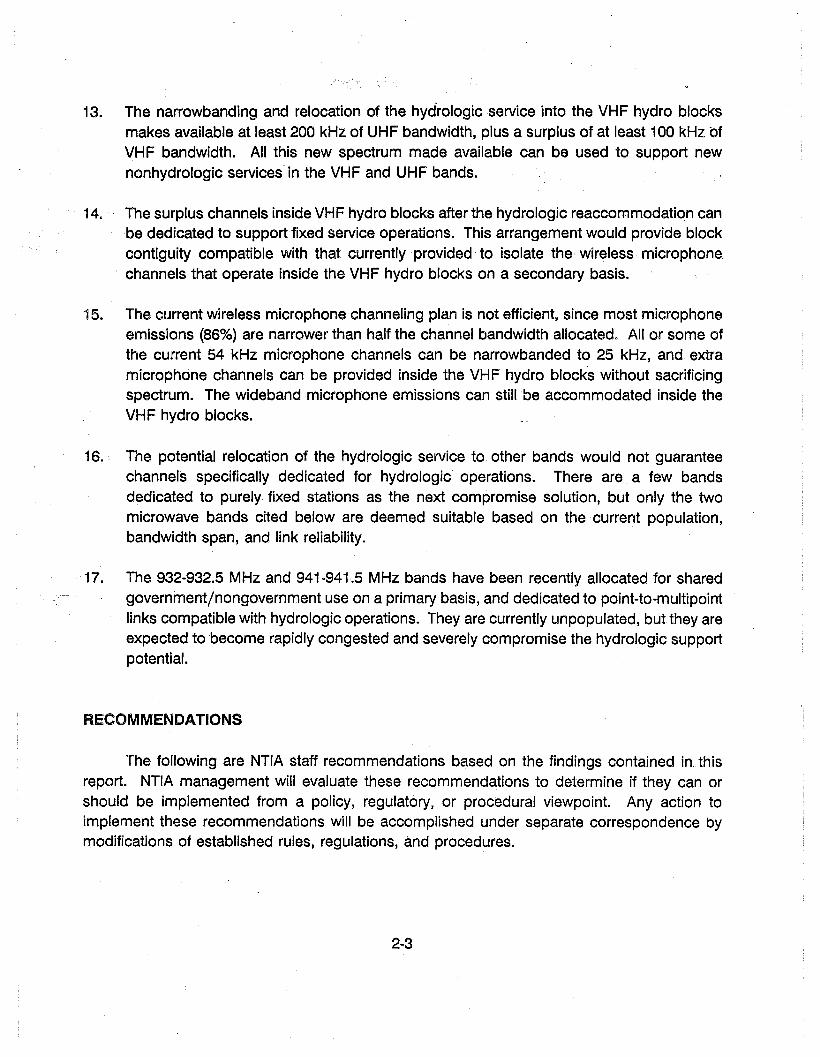
13. The narrowbanding and relocation of the hydrologic service into the VHF hydro blocksmakes available at least 200 kHz of UHF bandwidth, plus a surplus of at least 100 kHz ofVHF bandwidth. All this new spectrum made available can be used to support newnonhydrologic services in the VHF and UHF bands.
14. The surplus channels inside VHF hydro blocks after the hydrologic reaccommodation canbe dedicated to support fixed service operations. This arrangement would provide blockcontiguity compatible with that currently provided to isolate the wireless microphone.channels that operate inside the VHF hydro blocks on a secondary basis.
15. The current wireless microphone channeling plan is not efficient, since most microphoneemissions (86%) are narrower than half the channel bandwidth allocated. All or some ofthe current 54 kHz microphone channels can be narrowbanded to 25 kHz, and extramicrophone channels can be provided inside the VHF hydro blocks without sacrificingspectrum. The wideband microphone emissions can still be accommodated inside theVHF hydro blocks.
16. The potential relocation of the hydrologic service to other bands would not guaranteechannels specifically dedicated for hydrologic operations. There are a few bandsdedicated to purely fixed stations as the next compromise solution, but only the twomicrowave bands cited below are deemed suitable based on the current population,bandwidth span, and link reliability.
17. The 932-932.5 MHz and 941-941.5 MHz bands have been recently allocated for sharedgovernment/nongovernment use on a primary basis, and dedicated to point-to-multipointlinks compatible with hydrologic operations. They are currently unpopulated, but they areexpected to become rapidly congested and severely compromise the hydrologic supportpotential.
RECOMMENDATIONS
The following are NTIA staff recommendations based on the findings contained in thisreport. NTIA management will evaluate these recommendations to determine if they can orshould be implemented from a policy, regulatory, or procedural viewpoint. Any action toimplement these recommendations will be accomplished under separate correspondence bymodifications of established rules, regulations, and procedures.
2-3

1.
2.
3.
4.
5.
6.
7.
80
Hydrologic and quasi-hydrologic operations should be supported by hydrologic channelsallotted in the 162-174 MHz (VHF) band for government/nongovernment use on a nationalprimary basis.
A total of 28 VHF channels should be provided with a 12.5 kHz channel bandwidth. Thesechannels should be"located inside the current VHF hydro blocks, using the channelingplan shown in Figure 2·2, Option A, as next described.
The 20 current VHF hydrologic frequencies inside the hydro blocks should remainallocated to hydrologic operations, but their current 25 kHz channel bandwidths shouldbe reduced to 12.5 kHz. The 16 current VHF interstitial frequencies inside the hydroblocks should be allocated to form new channels with 12.5 kHz bandwidths, and used tosupport hydrologic and nonhydrologic operations as follows.
The eight interstitial frequencies inside the first and second VHF hydro blocks should beallocated to hydrologic operations, along with the current 20 hydrologic frequencies. Theeight interstitial frequencies inside the third and fourth hydro blocks should be allocatedto All Government Agencies (AGA) for fixed service operations.
Hydrologic operations in the 406.1-420 MHz (UHF) band should be relocated to the 12.5kHz hydrologic channels created inside the VHF hydro blocks. A total of 28 VHFhydrologic channels would be available as previously described.
Assignments in the current VHF or UHF hydrologic channels, or in their adjacent interstitialchannels, should be grandfathered in the 25 kHz to 12.5 kHz narrowband transition andchannel relocation process. New assignments in the current VHF hydrologic or interstitialchannels inside the hydro blocks should be required to satisfy the 12.5 kHz channelbandwidths after a set transition date that should coincide with the UHF hydrologicrelocation. This transition date should also conform with any date established for theimplementation of a 12.5 kHz channeling plan for the entire VHF band, or for any portionof this band that includes the current VHF hydro blocks. The transition dates suggestedare January 1, 1995, for all new equipment and January 1, 2005, for all equipment tooperate in 12.5 kHz VHF channel bandwidths.
The Hydrologic Subcommittee should maintain the responsibility for coordinatinghydrologic channel use requests to the Frequency Assignment Subcommittee, before andafter the narrowband transition and channel relocation process.
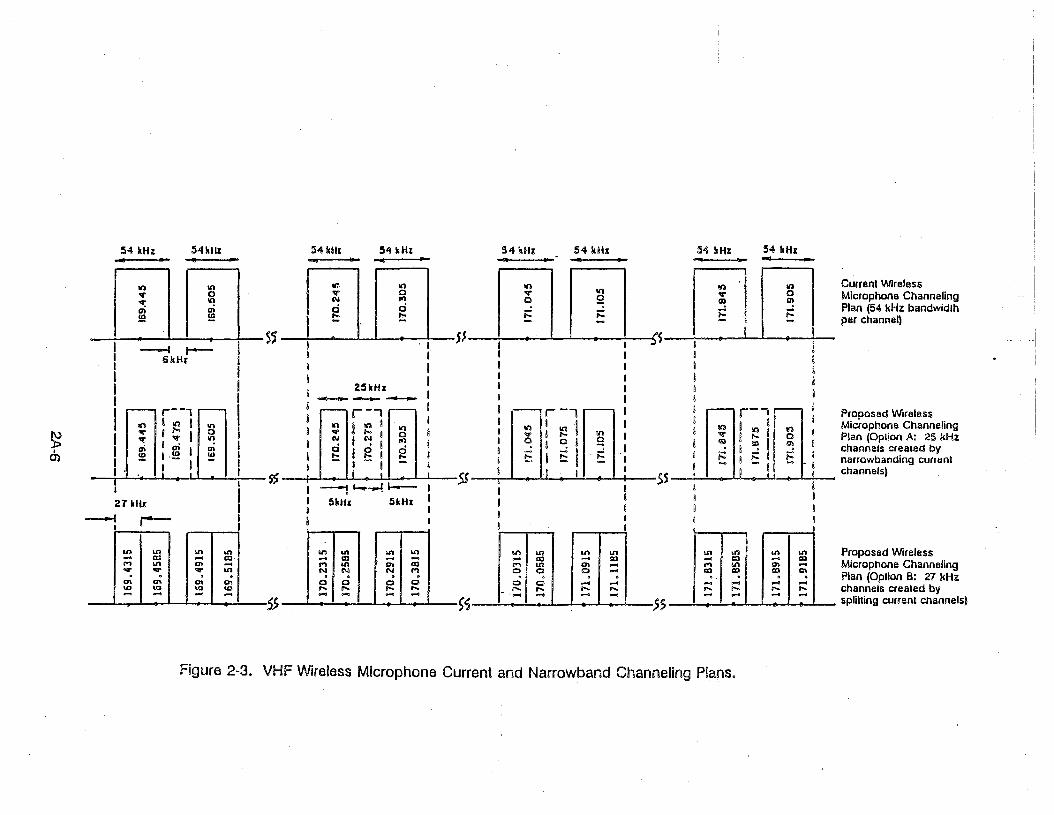
The current VHF wireless microphone channeling plan should be modified to provide 25kHz channel bandwidths as shown in Figure 2·3, Option A. Wireless microphone
operations with emission bandwidths not exceeding 54 kHz should still be supported, andassigned to any of the channel frequencies in the new channeling plan.
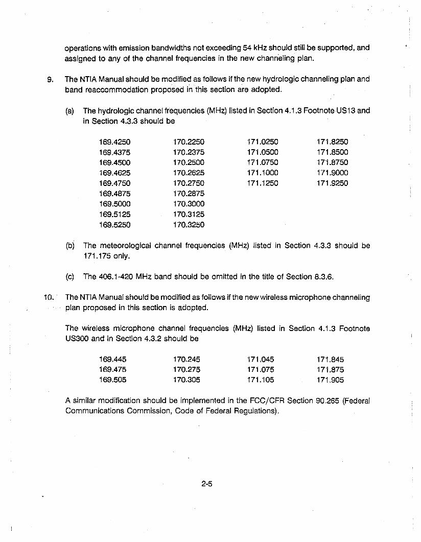
9. The NTIA Manual should be modified as follows if the new hydrologic channeling plan andband reaccommodation proposed in this section are adopted.
(a) The hydrologic channel frequencies (MHz) listed in SectionA.1.3 Footnote US13 andin Section 4.3.3 should be
169.4250 170.2250 171.0250 171.8250169.4375 170.2375 171.0500 171.8500169.4500 170.2500 171.0750 171.8750169.4625 170.2625 171.1000 171.9000169.4750 170.2750 171.1250 171.9250169.4875 170.2875169.5000 170.3000169.5125 170.3125169.5250 170.3250
(b) The meteorological channel frequencies (MHz) listed in Section 4.3.3 should be171.175 only.
(c) The 406.1-420 MHz band should be omitted in the title of Section 8.3.6.
10. The NTIA Manual should be modified as follows if the new wireless microphone channelingplan proposed in this section is adopted.
The wireless microphone channel frequencies (MHz) listed in Section 4.1.3 FootnoteUS300 and in Section 4.3.2 should be
169.445169.475169.505
170.245170.275170.305
171.045171.075171.105
171.845171.875171.905
A similar modification should be implemented in the FCCjCFR Section 90.265 (FederalCommunications Commission, Code of Federal Regulations).
2-5


SECTION 2A
SUMMARY
The assessment of current hydrologic and meteorological operations from a spectrummanagement standpoint requires awareness .of many complex and interrelated issues. Thissummary provides a proper perspective of the main issues and solution compromises involved,and compares various narrowband channeling plans and service recommendation options. Inparticular, a concise assessment table is presented to guide logical management decisionstowards an efficient spectrum utilization that alleviates hydrologic/nonhydrologic user congestionand mitigates mutual interference potential.
HYDROLOGIC SPECTRUM UTILIZATION
Hydrologic operations conducted by government and sponsored nongovernment agenciesprovide a valuable nationwide service, and spectrum support should be provided on a primarybasis. The spectrum utilization by the hydrologic emissions should also be efficient, not onlyto share the limited band resources with other important nonhydrologic services, but also tobenefit the hydrologic community itself in its spectrum usage.
The hydrologic operations are mainly supported by 21 VHF and 9 UHF hydrologicchannels, including one quasi-hydrologic channel in each band. The VHF usage is considerablymore than the UHF usage, with 2745 VHF and 362 UHF current hydrologic assignments in thehydrologic channels. There are also some hydrologic assignments in nonhydrologic channelsin both bands, representing 12% (VHF) and 4% (UHF) of the total hydrologic operations.
The hydrologic channels predominantly support more hydrologic than nonhydrologicassignments (88% VHF, 96% UHF), and with predominantly fixed hydrologic stations (91% VHF,99% UHF). Nonhydrologic assignments in hydrologic channels predominantly use mobile orland-mobile stations in the VHF band, and fixed stations in the UHF band.
HYDROLOGIC EMISSIONS AND BANDWIDTH CONSERVATION
A 25 kHz hydrologic channel bandwidth is provided in both bands. A 16 kHz assignedbandwidth predominantly represents the hydrologic operations, as well as the nonhydrologicoperations in hydrologic channels. This bandwidth usually supports two types of hydrologicemissions (F2D, F3E) regularly employed for remote data collection and backbone data/voicecommunications in the hydrologic operations.
2A-1

The F2D (data) emissions consist of an FSK data subcarrier modulating an FM carrier,and the F3E (voice) emissions consist of a single speech channel also modulating an FM carrier.The FSK audio baseband typically has a 2.3/2.8 kHz lowpass bandwidth for 300/1200 bps datarates, which matches the 3 kHz speech baseband occupancy to permit using common stationequipment for data and voice communications. The 1200' bps rate should be assumed to setcurrent standards, as increased throughput capabilities are being demanded to meet trafficrequirements.
The FSK audio subcarrier (audio tones) also supports a multitude of conventional FSKmodems, which are employed by the hydrologic networks and community facilities to provideautomated computer interfacing, data dissemination, and RS~232 standards conversion. The useof direct~carrier digital modulation technology for the data emissions would conserve bandwidth,but at a prohibitive cost in the massive amount of modem replacement and new dedicatedstation equipment (transmitters, repeaters, receivers) that would be needed.
The hydrologic emission bandwidth can be effectively reduced for spectrum conservationby using narrowband analog modulation technology, ~uch as amplitude compandored singlesideband (ACSB) or narrowband frequency modulation (NBFM), while preserving the existingdata/voice audio basebands in the hydrologic emissions. In particular, NBFM technologyrepresents a minimum impact solution in equipment modification and performance compromise,and it suffices to render less than 12.5 kHz emission bandwidths compatible with narrowbandchanneling plans.
WIRELESS MICROPHONE OPERATIONS
Wireless microphone wideband (54 kHz) channels are also provided in the VHF band,and support nonhydrologic government/nongovernment operations on an unprotectedsecondary basis. These channels are currently allotted as pairs inside blocks formed bycontiguous VHF hydrologic channels, which isolates the wireless microphone emissions andmitigates the mutual interference potential between them and other services in the band.
The wireless microphone emissions are predominantly much narrower than their 54 kHzchannel allocation. Only 14% of the microphone assignments have emission bandwidths of30 kHz or more, whereas 86% have 20 kHz or less emission bandwidth, so that the majorityoccupies less than half the channel bandwidth. The wideband microphones are also equallydistributed over all their channels, which is not efficient spectrum utilization; Le., all widebandchannels are currently supporting predominantly narrower microphone emissions.
2A-2

HYDROLOGIC NARROWBAND CHANNELING PLANS ANDREACCOMMODATION ASSESSMENT
The current UHF hydrologic channeling plan is inefficient, because only three of the ninechannels are contiguous as shown in Figure 2-1. The nonhydrologic gaps result in only twointerstitial channels reliable for hydrologic support, by having adjacent hydrologic channels onboth sides. The other interstitial channels have adjacent mobile and land-mobile operations onone side, which could interfere with hydrologic interstitial operations;
A 12.5 kHz UHF hydrologic channeling plan can provide only 11 narrowband channelswhen using the current hydrologic and their reliable interstitial frequencies, or only 18narrowband channels when splitting the current hydrologic channels, as shown in Figure 2~1.If the current 25 kHz UHF gaps between neighboring hydrologic channels were dedicated tohydrologic operations, the number of 25 kHz channels increases from 9 to 13, and the numberof 12.5 kHz channels increases from 11 to 23 or from 18 to 26, as shown in Figure 2-1.
Conversely, the current VHF hydrologic channeling plan is efficient, as 20 of the 21channels available form four blocks of five contiguous channels each. This renders 16 interstitialchannels reliable for hydrologic support, since they have adjacent hydrologic channels on bothsides. The channel contiguity also provides a 125 kHz spectral umbrella for two 54 kHz wirelessmicrophone channels inside each hydro block.
A 12.5 kHz VHF hydrologic channeling plan can be provided by narrowbanding the VHFhydrologic channels, and using their interstitial frequencies to create the other channels asshown in Figure 2-2, Option A. An alternative approach is to split the VHF hydrologic channelsinto narrowband pairs as shown in Figure 2-2- Option B, which would require a 6.25 kHz centerfrequency shift along with narrowbanding.
These VHF narrowband plans provide 36 (Option A) or 40 (Option B) total 12.5 kHzchannels inside the hydro blocks. These new channels could support the current VHFhydrologic channels (narrowbanded) and the current UHF hydrologic channels (relocated andnarrowbanded), and still leave a surplus of 12 kHz channels for nonhydrological support insidethe hydro blocks. These extra channels could be dedicated to fixed service operations, so asto help maintain the block isolation currently provided for tl1e VHF wireless microphon~ channels.
The VHF spectrum utilization by wireless microphones can itself be improved by creatingnarrowband channels from the current 54 kHz channels as shown in Figure 2-3. A frequencystability of about 15 ppm (± 2.5 kHz drift) or 20 ppm (± 3.5 kHz drift) would suffice for the 25 kHzor 27 kHz channel bandwidths, respectively.
2A-3

{
Current Plan,225 kHz, 9 channels,2 interstitial reliable
{
Current Narrowbandedvia hydros + interstitial,137.5 kHz, 11 channels
{
Current Narrowbandedvia splitting hydros,225 kHz, 18 channels
{
Current Plan + Gaps325 kHz, 13 channels10 interstitial reliable
{
Current + Gaps Narrowvia hydros + interstitial,287.5 kHz, 23 channels
{
Current + Gaps Narrowvia splitting hydras + gaps,325 kHz, 26 channels .
17575~ 75
~(lf~, . I S5 I I 5S I I
I' t JlJ nl 10 0 0 ~(2)' I I . 1 55 I I,- _I 1_ _ _ _"I: 12.5 12·.5 f II 12.5 12.5 12.5 12.5 II f II~ • i> i I lJ" i i} L ,.....,.,..., i I} i
~{ I r /I I V d ff _I ' au I
125 -2510
,' 125" -25" 25" -25 -:
: , I '~5 to LllIJI 1 ,, .. 75 1-. 175 • ,
I I i
! ~ SS~ra=wI -- 62.5 -- I II -. 162.5 -- I
I 1 RIii
I '51 i'i i5j r
_
J-l{.d-.16.LJL.L~":"':(::.L'-..L',t..,J..!--!-':.....x..II " _/I(Ii) I VA V d r /1 ~S ! "0 v a v t1I VI1 [/4 VA <5
~~
Figure 2-1. UHF Hydrologic Channeling Plan Options.

"" 0--."'- :~::l >.0-=
ls~ Hydro BLock
- 125 kHz ..
2nd Hydro Block
- 125 kHz -
3rd Hydro Block__ 125 kilz
4th lIydro Block__ 125 kilz ___
..... 0 ..... 0
~I~currenl HydroN III .... 0
to to to 0\ Channeling Plan. . . .... ... ... .... (25 kHz bandwidth,... ,... ,... ,...... ... ... ... per channel)
\
r-, JlI'l 0 lI'l 0 '" I "'.N '" .... 0 NI ::::.0 0 0 .... -. . . . .I '1.... ... ... .... .... 1-,.... .... .... ,... ,... .::::..... .... -I .... ...I ;S IH
I... -I I ,- I
675 kllz I I t 675 kHz II , I ~ ........................1..,-,,.....,.,,....-,'rnm 'roI I·: I (Proposed Hydro, I I I )Channeling PlanI . I I ) (Option A: 12.5 kHz
~ t ~ bandwidth per channel)IfI
675 kHz I1iii i <I I i< 8 i G i
IIII
III 0 lI'l 0 lI'l lI'l 0 ." 0 lI'lN lI'l .... 0 N N 01'\ .... 0 N~ -:r ~ lI'l 01'\ N N N <"'I ..,,;., . . . . . . . . .
0\ CI\ 0\ CI\ 0 0 0 0 0-0 -0 -0 -0 -0 .... ,.... .... ,.... ........ .... .... .... .... .... .... .... .... ....
I 55 ..... ~
(proposed Hydro)Channeling Plan .)(Option B: 12.5 kHz~ bandwidth per channel)
{
Current WirelessMicrophone ChannelingPlan (54 kHz bandwidthper channel)
-
..... I ..... t~ 0to I en ,. ..... I .... I..... ......... ! .... II --
, 54 kllz I S4 kllz II.. ~ I· .. II i • t .-----.
I I
r
,5
I i, 54 klh: I S4 kilz 'I
I" • ,- '" II I
IlI'l I .....~ 0, 0 I .... .... I ....
I .... ,...... . I ....I i
- I,.... I-I
I II II i
c..-.,
I I l I (I 'I ...'-;
Qj
• !, 54 kllz I S4 kl1z,- .. 1- ..,I I II ..... I ..... . ,, -:r I 0
N r'l I, . I.
I0 0
I,.... I ....
l... .....~ I I
. I 'I, 54 kHz I 54 kllz ".. .. I ..t I II I
I, III II III III ::; I ~ II
t I • ,! . II0\ I 0\ I'I ~ Ii ~ .11- II j
. . I I
.r
I oJ
I I
--i r----l L----I L...--5.5 kHz 6 kllz 5.5 kHz
~•01
Note: Proposed Hydrologic Channeling Plan Options:Option A (12.5 kHz bandwidth): case of hydrologic and interstitial frequencies preserved.Option 8 (12.5 kHz bandwidth): case of hydrologic channels split with hydrologic frequencies shifted,
and interstitial frequencies abolished.
Figure 2-2. VHF Hydrologic Current and Narrowband Channeling Plans.
Proposed WirelessMicrophone ChannelingPlan (Oplion A: 25 kHzchannels created bynailowbanding currentchannels)
54 kHz-54 kHz
i ,Ig
! III !g fll III I.,.i :;; I 0
I a:I "! R
9 j;: g ..: I ;::: iR !:: i - ii I I.5S
54 kHz
I I .III I It'I I i;; I .... IlI'l I
8 q I 9E I 1: I .j::; 8
i
II I i
:14 kHz
In~ Inn. I n I eo""...",'"~ g :; ~ Mla"p,,"n. Ch.nn.,ln,..:::; ...:..: Plan (54 kHz bandwidlh!::!:: !:: t: per channel)
S~ I • I SS I' e.I I i Ii I I Iii I I iI I 0 II I iI ._--~....- A A ~,..--'\~ I
54 kHz
III
25kHz I_______ I
IIIiII
54kHz
lI1I Ii).,. 0N I'l
g ci!::
55
IIIoIIIIn10
54kHz
~ I-6kHz
54 kUz-ll'l 10.,. 0"lI: ~/1l /1l!.!! !.!!
il',".'I," s) :'.lle!~.,11 5J
21 kilt
~ r--I
~en
on on o.n Ul-- lU ... lUM o.n <n ...... ... ... Ul
<n c;r; en 0:IQ ... IQ IQ... ... ... ...
S~
on In o.n U'l... aJ ... ...M o.n 0\ <IllN N N M. . . .0 0 c c.... .... .... ....... ... .... ... ss
on on .... Ul... a) -- a)M In <n ...0 0 0 --. . .0 0 .... ........ .... .... ........ ... ... ....
o.n Ul Ul o.n Proposed Wireless... C3 ... lUM In '" ... Microphone Channeling<Ill ~ co C\.. . . Plan (Option B: 27 kHz... ... .... -.... .... .... .... channels crealed by... ... .... ....
$) I splitting current channels)
Figure 2-3. VHF Wireless Microphone Current and Narrowband Channeling Plans.
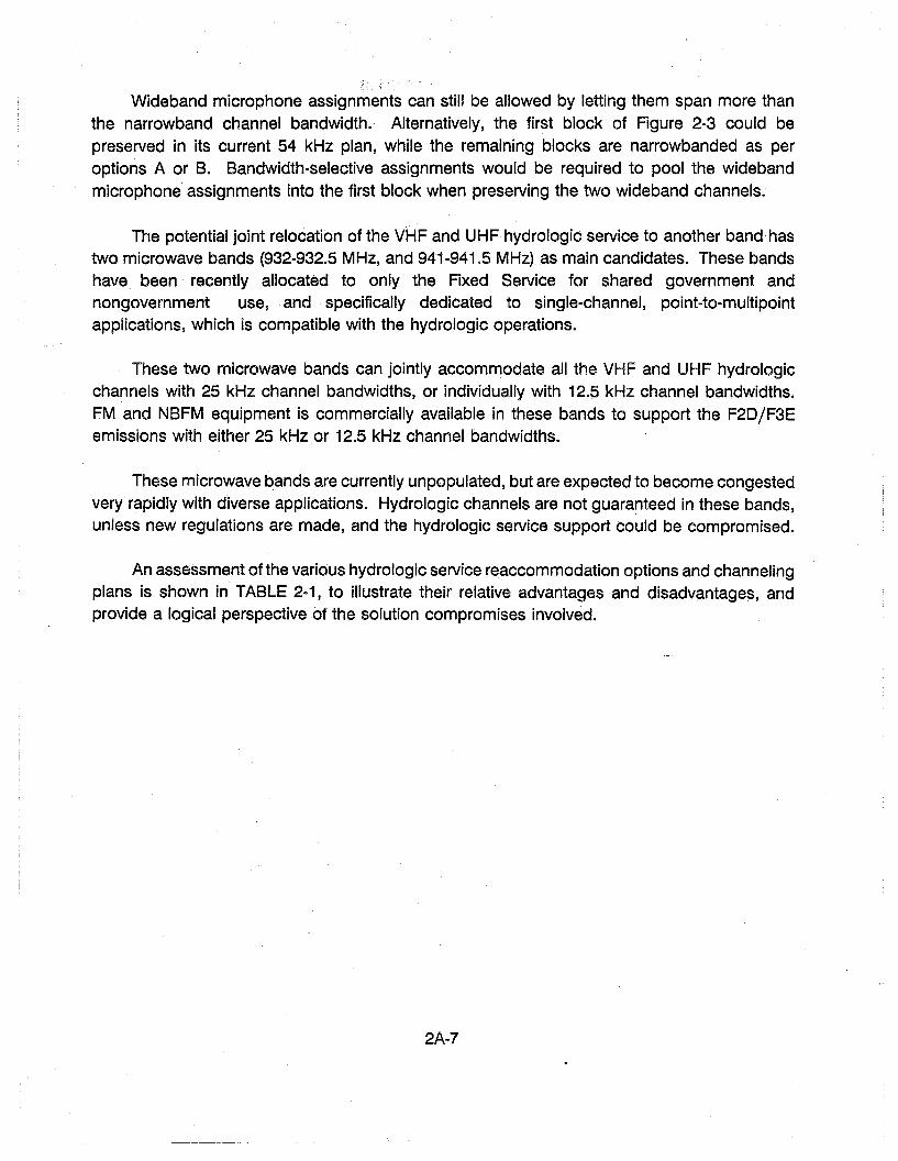
Wideband microphone assignments can still be allowed by letting them span more thanthe narrowband channel bandwidth.- Alternatively, the first block of Figure 2-3 could bepreserved in its current 54 kHz plan, while the remaining blocks are narrowbanded as peroptions A or B. Bandwidth-selective assignments would be required to pool the widebandmicrophone assignments into the first block when preserving the two wideband channels.
The potential joint relocation of the VHF and UHF hydrologic service to another band hastwo microwave bands (932-932.5 MHz, and 941-941.5 MHz) as main candidates. These bandshave been recently allocated to only the Fixed Service for shared government andnongovernment use, and specifically dedicated to single-channel, point-to-multipointapplications, which is compatible with the hydrologic operations.
These two microwave bands can jointly accommodate all the VHF and UHF hydrologicchannels with 25 kHz channel bandwidths, or individually with 12.5 kHz channel bandwidths.FM and NBFM equipment is commercially available in these bands to support the F2D/F3Eemissions with either 25 kHz or 12.5 kHz channel bandwidths.
These microwave bands are currently unpopulated, but are expected to become congestedvery rapidly with diverse applications. Hydrologic channels are not guara~teed in these bands,unless new regulations are made, and the hydrologic service support could be compromised.
An assessment of the various hydrologic service reaccommodation options and channelingplans is shown in TABLE 2-1, to illustrate their relative advantages and disadvantages, andprovide a logical perspective of the solution compromises involved.
2A-7

TABLE 2-1(page i of 3)
HYDROLOGIC SERVICE REACCOMMODATION ASSESSMENT
•
8 • • • • • • • • • • • • • • • eo. e m 8 • • • • • • • • 8 e 8 e • & • e 0 0 sea • • • • e e e e e e
•
2. Vllf wireless microphone channel:! 0
lose hydro block Isolation. •
e
RflWl~S
L The current 21 VHF and 9 UIIF hydrochanne 15 have 25 kllz bandw idlhs.and occupy a 525 kllz VHF and225 kllz UIIF tota I span.
4. The current 25 !<lIz nonhydro gallSIn the UIIF hydro blocks could lJeallocated for hydro support to havecant Igllolls channe 15 and ga In sOlliehydro bandwidth.
2. These channe hi current Iy support2745 VilF and 362 UHf hydro assignments, so that the channel usageIs lower at UHf than Vllf 011 theaverage.
3. The current UHf hydro plan IsInefficient, since the hydroblocks have few and usuallynoncontiguous channels. with only2 re lIab Ie Interstl tla I hydrochanllels.
"
"""
"<l
"""e""o"""....""
DISADVANTAGES
Hew UHf hydro spectrulll must be •created., Iionhydro operat Ions '"to be grandfalhered would be a epotential Interference source II
to new hydro chamle Is unt II II
phased out. II
• • em. e 0 eo. 8 • 8 • $ e 8 e 9 8
525 kllz extn hydro spectrum needed efor 30-channel support, 300 I<ilz II
extra stili needed for 21-channel eliUpport, (9 VHf channe Is absorlled "Into !II UIIF channe is). 0
l. aso \<;ilz extra hydro spectrumneeded for 30-channel support, andallocill IlIg the 25 kllz nonhyllro !lapswould not :iufflce (see figure 2-1).
4. 26-channel support provided viasplit channels requiring 6.25 klkshift ill current hydrologic ilndInterstitial center frequencies.
5. Ullf equipment not cOlnnerclaUyava Ilab Ie.
4. Only 13 total Ullf channels can besupported by allocat IlIg the current25 kill nonhyJro !laps.
(A.2) Case of 12.5 kllz 3. Only 37.5 kllz extrachannels spectrum needed for
21-channai :iupport
4. 23-cl1anne1 or 26-chanllelsupport call be providedby aHocating ahe 25 kllznonhydro gaps.
5. 23-channel support providedwithout shifting currenthydrologic or Interstitialcenter frequencies.
e - • • 8 • • 8 • • • • • • e e • 8 • G • e 8 8 • • • e • • e ~ efA. n Case of 25 Uh: 3. Ullf equ Ipment 3.
channe 15 CORlnerc la Ill{ ava Ilab Ie
oPTIons ADVANTAGES";,
(A) VIIF re locat Ion L Opens Vllf spectrum Lto UIIF band (525 kill liberated)
2. UHf hydro operationsare experienced
~I
<Xl

TABLE 2-1(page 2 of 3)
OI'TlOIIS ADVAUTAGES DISADVAUTAGES REHARKS .,
e 1. The .current VIIF hydro plan i's ,.(8) Ullf re loca t Ion 1. Opens UUF spectrum 8 eU Ic lent. since the hydro Ii locks
to VIlF band (225 kllz liberated) 9 have cant Iguous channe Is that• render 16 reliable Interstitial
2. VIIF hydro operations Cl hydro channels.are experienced. •
'" 2. The contiguous channels and3. Hlnlmum Impact 8 Interst It la I re liability fac Illtate
relocation since VIIF • the creation of 36 narrowbandusage predominates. 8 (12.5 klkl channe Is Ins Ide the
• • e 8 • • • • • • • • • • • • • • • • • e • • • • • • • 8 • • • • • • • • • • • • e I • • • • • • • • • • • • hydro blocks, and without any(8.i1 Case of 25 kllz 4. VIIF equipment 1. Incompatible with 12.5 kllz • center frequency shifts.
channels cOllmerclallyavallable. channe ling trend for ent Ire •band. 8
8 3. Alternatively, 40 protected5. VIIF wireless microphone 2. 225 kllz extra hydro spectrum • channels can be created Inside
~Ichannels keep hydro needed for 3D-channel support • the hydrologic block by splittingblock Isolation. (severely augments band • current channe Is, but requl ring
congest Ion). • 6.25 kllz center frequency shlfls.•6. Current 2\ hydro and 16 3. Absorption of UIIF hydras by •reliable Interstitial current VIIF hydras does not • 4. 100 current dlstrlbutllXl asslI~lIcnts
channels may suffice to help relieve VIIF band congestion. • In the VIIF wireless microphonesupport entire UHF hydro .. channels Is not efficient. Allservice. • e Igilt channe Is lire wIdeband and
• I • • • • • • • • • • • • • • • • • • • • e • • • • • • • • • • • • • • • • • • • • • •• • • • • • • e I • 8 a11 support a minority of wldeband(8.2) Case of 12.5 kllz 4. Compatible with 12.5 kllz 1. VHF IIOFH equlplnent cOlllllerclally e mlcrqioles, IIlag willI til! IIUjorlly
channels channeling trend for', available In Europe but not U.S. 8 of narrower microphones lhal occupyentire band. (ACS8 available In U.S.) • less than ha 1f the channe I
8 bandwidth.s
5. 36-channel Dr -to-channel 2. VIIF wireless microphone channels 8 5. fust wireless mlc~mes onlsslalssupport can be provided could lose their block Isolation • are much narrower than the hydroby narrowbandlng current depending on surplus dedication • block Isolation span provided.hydro blocks. (e.g., surplus used for Mobile •or land-Mobile Services). (;
6. Opens VIIF •spectrum. AII 30 •hydro channels can be accollloodatedInside current VIIf hydro blocks, •and st 111 leave a sllrp Ius of 75 kllz •(Opt Ion A) or 125 kllz (Opt Ion BI •
(Continues on lata I Ins Ide blocks, plus 2.5 kllz •next page) outside In quasi-hydro slot. ..

TABLE 2-1(paga 3 of 3)
o • • • • • • e • 0 • • • " e • • • ~ • • • "
ilEIWlU
Vlre ieu microphone chanlle is canbe PlildQ eft Ie lellt by narrol1banlHII!JIIllSt or al154 Uk channels. Ibrea25 Idll: or four 21 Ull naffo~lhalld
channels can be cualed 111511.111a hydro block.
II.
@ e e • " III " e " • " e • • • e e ""
••••••••••e
...."
Surplus dedlcatRon till FixedSe!"11 Ice wou \d require re locationwllhln VUf banI! IheU 10 ga'nspeclrlllPu for Hoblle and lalldtlob I III Sarv ices
3.
P8SAnVl\,nAGESADVAIIlAIiESornOli5
'D.2) Case of 12.5 Uh: A 1.channc hi
(COlli hlllcdt
Surplull Inside new narrowbandblocks hi open spectrullI(besides ullr hydros) tosupport oOllhyc.lro liervlces."Ire loas llIlcrophollo channe Iscan keep most (Uptlon A) orall (Option 8) block IsolationIf sijrptus dedlcate~ to fixedServlcQ (polnt-t~-lIIlilllpollltl.
8. Fixed Service relocation toiurp Ius channe Iii Is cOlllpatibleHnil U. 5 kllz chaone 1I0g plallbaing del/elpped for elltire band.
• • • • • • • • • • • • & • • • 8 • & • • • 0 • • • • • • • • • • •
;). lwo mlcroliave luhbands willi6110 kill span each (932-932. faUllz 941-94!. fa ·'IIIz) recent llfopened rOf point-la-mull Ipointfixed support (hydro 0lleut Ionscompatib leL
4. 'lOfH equipment cOllmorc la 11)'ilva I lab III to support thoumicrowave bands with ellher25 kill or 12.5 idb: chaune'iJandwldlhs. Current or narrowband f20/F3E hydro cmhs lOllS CIU1be supported whl1Q pruorv Ingdata/volca audio buelJands.
4. IUcrowave bauds lire nOIll v Irt18ill By ..Ullllopllhled. hul &\ho IlKPCChli lo ..get f! 11011 vef)' rallhJly !'lUll dlvenUli ..api11lcat Ions. lIydro)oglc lliurvic8 ".511pport can be COlllllfomlsel!. .. .,
e
n!crow,&lIo bambi are for shul!ldl fJ
UQVCnllllcnl/llulI!JovenllllclI~ 1I1111JlQr~ "lIoliBlllc If Ie hl/dro cha!llull dlld!caUOi8 "emlen lIew fll{JulaUOII:l il"!! BDiU!Q. ..
.."".."
I".~
...."I"; •
"
UIQ lOll hI' other pllre Ill' fillet! Serlllc@lia6,d5 are be 801ll 20 11I1l. tl1I5~ An
IIlllhof limited III billu~~ltlth 5pall,or wi II fit hydrQ 511an l'uM Ill.
"
•"
•III
<I>
•
•" L
tlax !anulft Impact In eql!llllIIen~
rllil bcemcnt ilillOlllll.
810 8,,,,tlro microwave operat ionIIlKpurlc6lco.
I.
if.
3.
Opens Vllf ilnd ullr spectrulft(15U Idll tola I liberated)
H!crowlIve blinds cllrrent'lfavalll1ble lor purely FixedSenlcll lupport, !lull withcno"uh biilllwldih lilian toacconlllOlla to ai' 30 hydrochanna hi will! 25 j(1I1 orlUi ~liz I) lalll!.
I.
2.
Vllf lind Ullfre local 1011 toolher banalh)
lei
~-4
a

SECTION 3
RULES AND REGULATIONS
NATIONAL FREQUENCY ALLOCATIONS
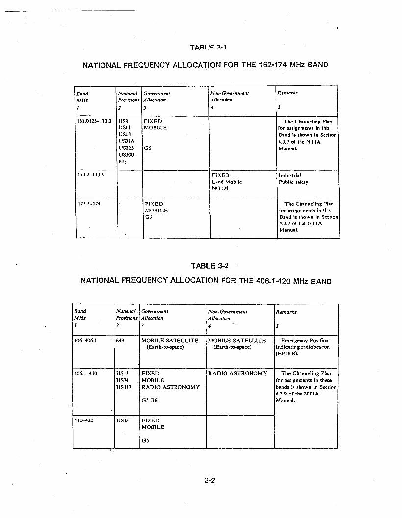
The current version of the NTIA Manual of Regulat~ons and Procedures for Federal RadioFrequency Management (see Reference 1) has the National Frequency Allocations shown inTABLES 3-1 (VHF) and 3-2 (UHF) for the 162-174 MHz band (VH F) and 406.1-420 MHz band(UHF), respectively. The bands support the Fixed, Mobile, and Radio Astronomy services forgovernment and/or nongovernment operations on a primary basis, as well as Land Mobilenongovernment operations on a secondary basis.
There are also many footnote regulations pertaining to specific national government (G,US), national nongovernment (NG, US) or international (#) operations in certain frequencies orband portions, as summarized in TABLES 3-3 (VHF) and 3-4 (UHF). These tables also includethe footnotes to the Channeling Plan (FCP) for the VHF and UHF bands pertaining to thehydrologic/meteorological and quasi-hydrologic channels.
There are 20 VHF and 8 UHF channels allotted to hydrologic operations, and 1 VHF and1 UHF channel allotted to meteorological and quasi-hydrological operations, as listed in TABLE3-5 (NTIA Manual, Section 4.3.3). There is no more specific definition of these operations, otherthan stating that their station emissions are used for the automatic transmission of hydrologicand/or meteorological data (NTIA Manual, Section 6.1.1).
The hydrologic channels are mainly to be used for hydrologic operations by the (Federal)Government agencies, or by nongovernment agencies engaged in hydrologic operations incooperation with the government agencies (NTIA Manual, Section 4.3.4). Nongovernmentoperations are identified as fixed hydrologic/meteorological stations causing no interference togovernment stations (NTIA Manual, Table of Frequency Allocations, US13 Footnote). Thenongovernment usage presently represents about one-third ofthe hydrologic channel operations.
The hydrologic channels can also be used for nonhydrologic operations by the governmentagencies, usually after other possibilities are exhausted, and provided that such usage doesnot conflict with existing or projected hydrologic operations (NTIA Manual, Section 8.4.6). Thereare presently government nonhydrologic operations in some hydrologic channels, as well asgovernment/nongovernment hydrologic operations in channels other than those reserved forhydrologic operations, as shown later in this report.
3-1
NATIONAL FREQUENCY ALLOCATION FOR THE 162-174 MHz BAND
Bantl National Gavunmttnl Non·Govttrnmen' Rtmarks
MHz Prov;jions Allocation Allocation
J 1 J -f J
162.012.5-17J.2 US8 FIXED The Channeling Planusn t-mOlLE for assignments in thisUSIJ Band is shown in SectionUS216 U.1 of the NTIAUS223 OS Manual.USJOO61J
173.2-113.4 FIXED IndustrialLand Mobile Public safetyNOIH
113.4-114 FIXED The Channeling PlanMonlLE for assignments in thisOS Band is shown in Section
4.3.7 of the NTIAManual.
TABLE 3-2
NATIONAL FREQUENCY ALLOCATION FOR THE 406.1-420 MHz BAND
Band National Government Non-Government RemarksMHz Provisions Allocation Allocation
I 2 J " 5...
.406-406.1 649 MOBILE-SATELLITE MOBILE-SATELLITE Emergency Position-(Earth-to-space) (Earth-to-space) Indicating radiobeacon
(EPIRB).
406.1-410 US13 FIXED RADIO ASTRONOMY The Channeling PlanUS74 MOBILE for assignments in theseUSI17 RADIO ASTRONOMY bands is shown in Section
4.3.9 of the NTIA0506 Manual.
410-420 USl3 FIXEDMOBILE
05
3-2

VHF BAND ALLOCATION SUMMARY (162-174 MHz)
162.0125-173.2 MHz:
G5:
US8:
USll:
USB:
US216:
US223:
US300:
613:
FCP8:
171.175 MHz:
FCP9:
173.2~173.4 MHz:
NG124:
173.4-174 MHz:
G5:
Fixed and Mobile Service (Government, Primary)
non-military agencies
nine channels for nonfederal forest firefighting agencies (fixed, land,and land mobile stations), two of them also for nonfederal conservationagencies (mobile relay stations)
two channels for nongovernment remote pickup broadcast (base andland mobile stations) and nongovernment public safety radio (fixed,base, and land mobile stations)
twenty hydrologic/meteorological channels can be authorized tonongovernment fixed stations associated with government operations,provided no interference is caused to government stations.
a 25 kHz subband around 163.25 MHz for government/nongovernmentmedical radio communications
one maritime mobile channel (162.025 MHz) for US/Canada bordertransmissions
eight channels for government/nongovernment wireless microphoneoperations on a secondary basis,
maritime mobile priority channels below 162.05 MHz
Primarily for hydrologic use. Shared with nongovernment under noteUSB.
Fixed and Mobile Service (Government, Primary)
Primarily for meteorological and quasi-hydrologic operations outsidethe purview of the Hydrology Subcommittee.
Fixed Service (Nongovernment, Primary)Land Mobile Service (Nongovernment, Secondary)
Low-power police radio transmitter on a secondary, noninterference,basis
Fixed and Mobile Service (Government, Primary)
non-military agencies
3-3
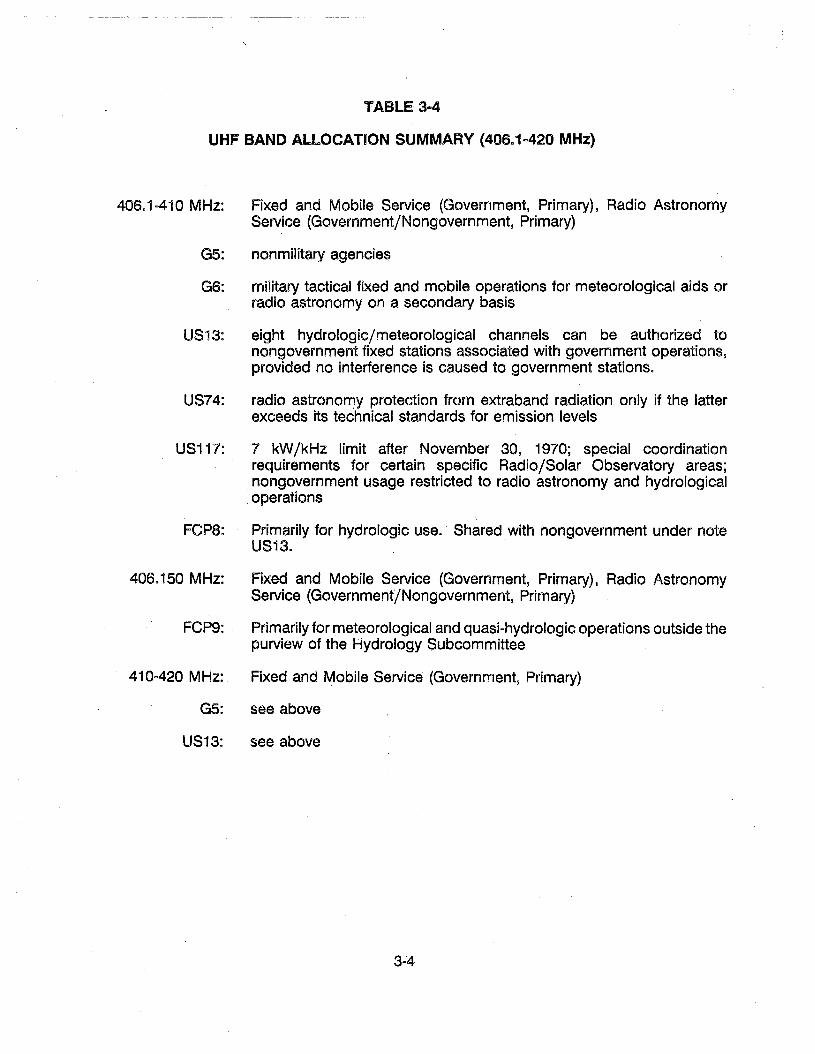
TABLE 3m4
UHF BAND ALLOCATION SUMMARY (40S.1 a 420 MHz)
406.1 ~41 0 MHz: Fixed and Mobile Service (Government, Primary), Radio AstronomyService (Government/Nongovernment, Primary)
G5: nonmilitary agencies
G6: military tactical fixed and mobile operations for meteorological aids orradio astronomy on a secondary basis
US13: eight hydrologic/meteorological channels can be authorized tonongovernment fixed stations associated with government operations,provided no interference is caused to government stations.
US74: radio astronorryy protection from extraband radiation only if the latterexceeds its technical standards for emission levels
US117: 7 kW/kHz limit after November 30, 1970; special coordinationrequirements for certain specific Radio/Solar Observatory areas;nongovernment usage restricted to radio astronomy and hydrologicaloperations
\
FCP8: Primarily for hydrologic use. Shared with nongovernment under noteUS13.
406.150 MHz: Fixed and Mobile Service (Government, Primary), Radio AstronomyService (Government/Nongovernment, Primary)
FCP9:. Primarily for meteorological and quasi-hydrologic operations outside thepurview of the Hydrology Subcommittee
410 e 420 MHz: Fixed and ~obile Service (Government, Primary)
G5: see above
US13: see above
3-4

TABLE 3-5
HYDROLOGIC AND METEOROLOGICAL CHANNEL FREQUENCIES (MHz)
VHF· HYDROLOGIC CHANNELS UHF HYDROLOGIC CHANNELS
• • • • • • • • • • • • • • • •169.425 171.025 406.125 412.625169.450 171. 050 406.175 412.675169.475 171.075 • • • • • • • •169.500 171. 100 409.675 412.725169.525 171.125 409.725 412.775• • • • • • • • • • • • • • • •170.225 171.825170.250 171.850 VHF METEOROLOGICAL AND170.275 171.875 QUASI-HYDROLOGIC CHANNEL170.300 171. 900170.325 171. 925 171.175• • • • • • • •
UHF METEOROLOGICAL ANDQUASI-HYDROLOGIC CHANNEL
406.150
TABLE 3-6
VHF WIRELESS MICROPHONE CHANNEL FREQUENCIES (MHz)
" ... • • • •169.445 171. 045169.505 171.105
• • • • • • • •170.245 1'71. 845170.305 I'll .905• • • • • • • •
3-5

- ----------- ----
There are also eight VHF channels allotted to wireless microphone operations on anunprotected, noninterfering, secondary basis relative to other authorized services (NTIA Manual,Section 4.3.2). These wireless microphone channels are centered offset by ±5 kHz relative tosome of the VHF hydrologic channels, as listed in TABLE 3~6. There are no UHF channelsallotted to wireless microphone operations.
The wireless microphone operations are also addressed in the Federal CommunicationsCommission-Code of Federal Regulations (FCC-CFR), Part 90.17. The 169-172 MHz band isallocated to the Mobile Service and, by footnote 27, some frequencies in this band are assignedfor low power wireless microphones. Part 90.265 of the FCC-CFR identifies the wirelessmicrophone frequencies and operational specifications such as emission bandwidth, outputpower, oscillator drift, interference, etc., which are similar to those in the NTIA Manual, Section4.3.2.
Wireless microphone operations are also authorized by the FCC-CFR, Part 74.801-802, aslow power auxiliary stations that can transmit over distances of approximately 100 meters. Thereare various frequency bands available for these wireless microphone operations, ranging from26.1-26.48 MHz at the low end to 944.0-952.0 MHz at the high end.
There are two types of wireless microphone applications. The operations supported by the169-172 MHz band (Part 90.265) represent the general purpose application (e.g., churches,lectures, concerts, sports, fast food, banks, etc.); whereas those supported by the 172-216 MHzband (Part 74.802) represent strictly broadcast applications (e.g., television, film production,cable, reporting).
CHANNELING PLANS AND PROVISIONS
There are channeling plans specified for the government assignments in the VHF andUHF bands in question (NTIA Manual, Sections 4.3.7 to 4.3.10). The 162.0125-173.2 MHz VHFsubband (which contains all VHF hydrologic channels) consists of 15 blocks of contiguous 25kHz channels, with variable capacity for block, and with consecutive blocks separated by one12.5 kHz splinter channel (plus one 25 kHz splinter channel at the end). The 173.4-174 MHzVHF subband (which has no hydrologic channels) consists of one block of contiguous 50 kHzchannels without splinter channels.
The entire 406.1-420 MHz UHF band consists of four blocks of contiguous 25 kHzchannels, with variable capacity for block, and with consecutive blocks separated by one 25kHz splinter channel (plus one 25 kHz splinter channel at the end). There are 40 noncontiguous25 kHz channels spread throughout the four blocks that are designated for trunked land-mobileoperations.
3-6
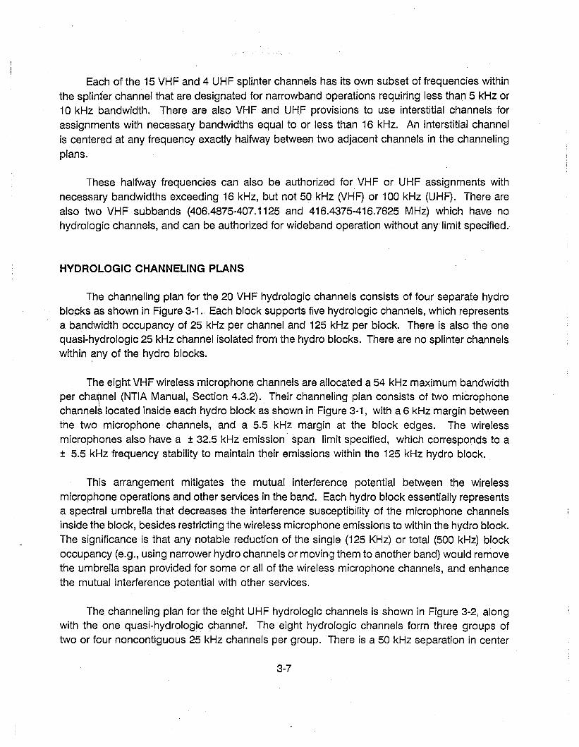
Each of the 15 VHF and 4 UHF splinter channels has its own subset of frequencies withinthe splinter channel that are designated for narrowband operations requiring less than 5 kHz or10kHz bandwidth. There are also VHF and UHF provisions to use interstitial channels forassignments with necessa~y bandwidths equal to or less than 16 kHz. An interstitial channelis centered at any frequency exactly halfway between tvvo adjacent channels in the channelingplans.
These halfway frequencies can also be authorized for VHF or UHF assignments withnecessary bandwidths exceeding 16 kHz, but not 50 kHz (VHF) or 100 kHz (UHF). There arealso two VHF subbands (406.4875-407.1125 and 416.4375-416.7625 MHz) which have nohydrologic channels, and can be authorized for wideband operation without any limit specified.
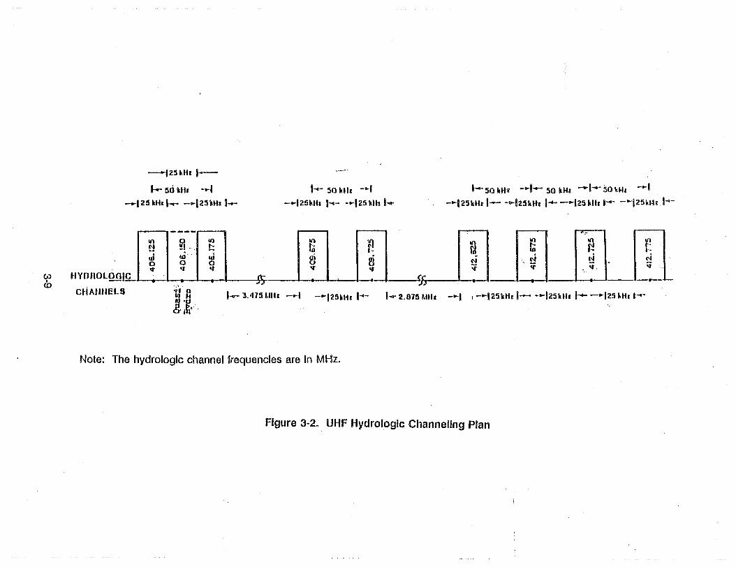
HYDROLOGIC CHANNELING PLANS
The channeling plan for the 20 VHF hydrologic channels consists of four separate hydroblocks as shown in Figure 3-1. Each block supports five hydrologic channels, which representsa bandwidth occupancy of 25 kHz per channel and 125 kHz per block. There is also the onequasi-hydrologic 25 kHz channel isolated from the hydro blocks. There are no splinter channelswithin any of the hydro blocks.
The eight VHF wireless microphone channels are allocated a 54 kHz maximum bandwidthper chal(lnel (NTIA Manual, Section 4.3.2). Their channeling plan consists of two microphonechannels located inside each hydro block as shown in Figure 3-1, with a 6 kHz margin betweenthe two microphone channels, and a 5.5 kHz margin at the block edges. The wirelessmicrophones also have a ± 32.5 kHz emission span limit specified, which corresponds to a± 5.5 kHz frequency stability to maintain their emissions within the 125 kHz hydro block.
This arrangement mitigates the mutual interference potential between the wirelessmicrophone operations and other services in the band. Each hydro block essentially representsa spectral umbrella that decreases the interference susceptibility of the microphone channelsinside the block, besides restricting the wireless microphone emissions to within the hydro block.The significance is that any notable reduction of the single (125 KHz) or total (500 kHz) blockoccupancy (e.g., using narrower hydro channels or movin!;;) them to another band) would removethe umbrella span provided for some or all of the wireless microphone channels, and enhancethe mutual interference potential with other services.
The channeling plan for the eight UHF hydrologic channels is shown in Figure 3-2, alongwith the one quasi-hydrologic channel. The eight hydrologic channels form three groups oftwo or four noncontiguous 25 kHz channels per group. There is a 50 kHz separation in center
3-7

aro If)4:ll
~rlI• •rl rl
t-- i i'M I, M
I r,... .-
4th lIy.lro II Iaell
--~
e-·-.-I
IIII
I5/1 1\llz I
li....--.... I.------. I
I III 1
I ~ I1 ....1 !I !::; I
.1 &- I
.-._,-0 III
gl~m '"!4 01 lUIi • , .
.-£ .-1 .-. r'h h ." ".-t rl 0-1 r-t
--e- 115 ItIlz
, S~ II lb.-4-1-
lrd 'llydro 'DloeD,
~10 IIli 0 E~ r-. 0
a to rl• • • • @
.-8 .-8 rl rl~h '" !::t '",-n rl .., rl
-+-'--.- -r
" ·u .~-'...c--125 1(lIz .... g~.
r-,'lill &1\t!:il fJI q 0
8~1 ~I ;..q rl
-W-1JS--I • •I 615 kUz
II
2nd lIydro Dlod'
.... 125 I<lIz ......
lot Ilydro Block
oofI.- 125 ldh: ..
~o lI\ua~ ~OLlIlilO I~1'1 lib "', 0 1'1 r- lib D 0 r-
o.t '" 't lib III N • .. C'l I... ell. &. til'
m m m m moo a a aIII .n III tlJ .0, "" " " "rl rl rl M M rl M rl M M
-.- -.- -r - -~S- -.- r- - -.-I_j~I I ,.. • I I I.. &-1I I I 675 I<lIz II I liB RIU" II I I I II I I
I I I I I I I-
I I I I I r: ~~ "11& I ~~ ItUz 5~ I<liz I 5~ Mh. IS4 IlIlz I ~~ KIU1/;I ~--t-II 4 ~I I I :04 .....c ~ I'" ..... B......... 10- !
I I I I I I II U\ I_ Of)' If) I III If) I8 "'I a ~ a I ~I ~- i 8~ e--: I ~ ~ !I 0\ a 0\ I a I a I.-I I8 <0 8 ..0 r-. I ,.... ,.... I8 rl I_ M rl rl rl I
" Iii'-F. - ,-jj I. .• -J-J:; ,
II I II-.-1 1- i
II 6 Illb I
-- ~- -~II--5.5 I!liz 5.5 ltliz
w~
Note: The hydrologic and wir~less microphone channel frequencies are in MHz. i-
I,, I
Figure 3-1. VHF·Hydrologlc Chi,lnnellng Pian II(Top: iHydrologlc Channels; BoUom; Wireless Microphone Channels)
,
-125ilHr I-
t-- 50 "Hr ....1_125 "Ih l--.- - ...125Uh 1--
1-1- 50 UII -.-1- ...125kHI 1-1- ·"'125 kll! I-q.
1- 50 uta -t-I...- 50 Uh -1....- 50 Uh - ...1-"'1 25Uh 1- -"'125"Hr 1-..- - ....125 klh ...... - ....i25Hh ,...-
---- "'"III 0 10 10 n a ~
10 r.N !!! '- t: tii f-!--: w- ac 1-·w .0 2i ffi ,ci ci N0 0 0 N
\iOGle
.,. .,. <t .,. <t \i .,. , <t •It- rr
..
.." IIc.>•(0
HVOnol.
C~iAlIfIElS '/-1 t:~'a&It·-
1-- 3.'115 "'Ul - ....1 - ....125kH' 1"'- '-q. 2.075 "'''1 -.... j ,-.... j25Uh 1- -"'125kttr 1-..- - ....125 HI! 1....-
Note: The hydrologic channel frequencies are In MHz.
Figure 3-2. UHF Hydrologic Channeling Plan
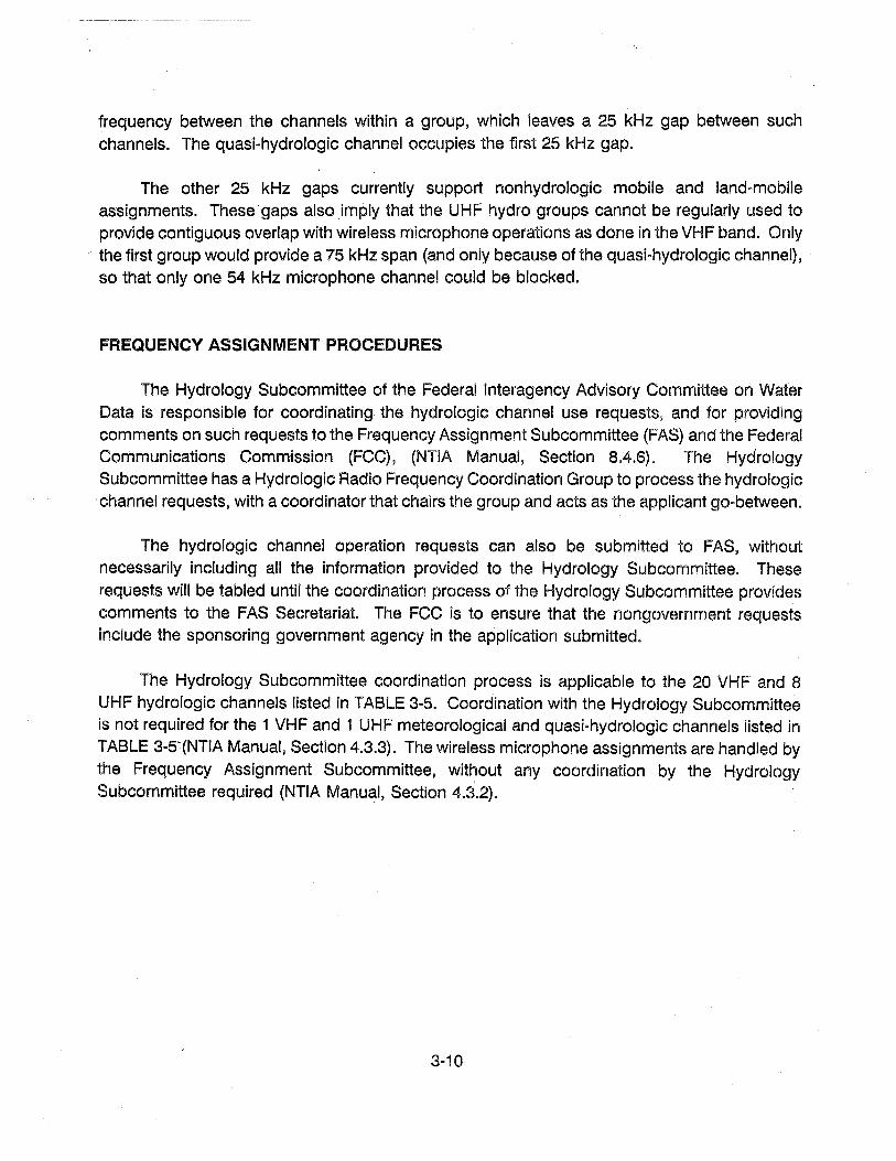
frequency between the channels within a group, which leaves a 25 kHz gap between suchchannels. The quasi-hydrologic channel occupies the first 25 kHz gap.
The other 25 kHz gaps currently support nonhydrologic mobile and land-mobileassignments. These "gaps also imply that the UHF hydro groups cannot be regularly used toprovide contiguous overlap with wireless microphone operations as done in the VHF band. Onlythe first group would provide a 75 kHz span (and only because of the quasi-hydrologic channel),so that only one 54 kHz microphone channel could be blocked.
FREQUENCY ASSIGNMENT PROCEDURES
The Hydrology Subcommittee of the Federal Interagency Advisory Committee on WaterData is responsible for coordinating the hydrologic channel use requests, and for providingcomments on such requests to the Frequency Assignment Subcommittee (FAS) and the FederalCommunications Commission (FCC), (NTIA Manual, Section 8.4.6). The HydrologySubcommittee has a Hydrologic Radio Frequency Coordination Group to process the hydrologicchannel requests, with a coordinator that chairs the group and acts as the applicant gO-between.
The hydrologic channel operation requests can also be submitted to FAS, withoutnecessarily including all the information provided to the Hydrology Subcommittee. Theserequests will be tabled until the coordination process of the Hydrology Subcommittee providescomments to the FAS Secretariat The FCC is to ensure that the nongovernment requestsinclude the sponsoring government agency in the application submitted.
The Hydrology Subcommittee coordination process is applicable to the 20 VHF and 8UHF hydrologic channels listed in TABLE 3-5. Coordination with the Hydrology Subcommitteeis not required for the 1 VHF and 1 UHF meteorological and quasi..hydrologic channels listed inTABLE 3-S-(NTIA Manual, Section 4.3.3}. The wireless microphone assignments are handled bythe Frequency Assignment Subcommittee, without any coordination by the HydrologySubcommittee required (NTIA Manual, Section 4.3.2).
3-10

SECTION 4
HYDROlOGICjNONHYDROlOGIC AND WIRELESS MICROPHONE ASSIGNMENTS
HYDROlOGICjNONHYDROlOGIC ASSIGNMENTS
The Government Master File (GMF) was investigated to develop a proper perspective ofthe hydrologic assignments and channel usage by govemment and nongovernment agencies.The following types of assignments were found in the GMF records:
CJ Hydrologic operations assigned to hydrologic channels
.. Nonhydrologic operations assigned to hydrologic channels
• Hydrologic operations assigned to nonhydrologic channels
The hydrologic operations are distinguished in the GMF records by the letter H includedin the station class designator for at least one of the record stations. There can be more thanone station per assignment, or more than one emission per station, as described later. Hence,careful accounting should be made when analyzing records or tallying populations, so as toavoid erroneous or misleading scenario descriptions.
DISTRIBUTION OF ASSIGNMENTS ANp CHANNEL USAGE
The population and distribution of the assignments in question is shown in Figures 4-1(VHF) and 4-2 (UHF), along with the wireless microphone assignments. The hydrologic versusnonhydrologic operation breakdown is also provided for the hydrologic channels in each figure.There is a total of 3117 (VHF) and 378 (UHF) hydrologic channel assignments, and thehydrologic operations represent 88% (VHF) and 96% (UHF) of these assignments.
There are also hydrologic operations in 28 (VHF) and 11 (UHF) nonhydrologic channels,representing 12% (VHF) and 4% (UHF) of all hydrologic operations in the band. In fact, thenumber of hydrologic operations in nonhydrologic channels (384 VHF, 15 UHF) is very close tothe number of nonhydrologic operations in hydrologic channels (372 VHF, 16 UHF). A summaryof the hydrologicjnonhydrologic operations and channel usage is presented in TABLE 4-1.
4-1

U!
~
t\l
"I lnono InaCK
I---IU m. ----t,I
2.
an~ l'YORO IILOCK
l-IUWI8 -t
o
a~~-'LC':'~IIA • .aH liS.
a,c8 uyono nOCK ft~~~b 4!h "YDnO IIl0CK
,. IU'KI -t -tU...... l-IUl... --i
,,0
o
..;i
..~~ ~
xe;e
§E
figure 4-1. Distribution and population of VHf assignments
Top: HydrologlcjNonhydrologlc assignments In hydrologic channels(Note: top number for nonhydrologlc,
bottom number for hydrologic)
Middle: Hydrologic asslgnme~ts In nonhydrologlc chan~elsI ~ ~
: I
Bottom: Wireless microphone assignments In wireless microphone channels

----125 kHz t--
I-- 50 kHz ~ ~ 50 kHz -J-.f25kHz~ ~25kHz~ 3.475Mlb ~25k11z I-- --t25kHz J- 2.875 MHz
I- 50 kllz -t- 50 ktlz -f-- 50 kHz ~
--125kHz I-- ~25kHz I--~25 kHz t-- -J25kHZ J-
"3 2{' ,2
(0(0
5473 . l /. 77 (I ,3 f 12 70 43 r 36 IOGiC n- Cr'
-JJ.J~
HYDROL
CHANNELS If) 0 If) If) If) 10 If) 10 l!?N If) I'- I'- t\I t\I I'-~- - ID I'- ID ID I'-
ui ID ui gj ~ t\I t\I t\I (\J0 0 0~ orq- <;t- <;t- <;t- v .,. .,.
.J:-l> --125kHz l-- --t25kUz .....-
7 B
NON-HYDROLOGIC S5 I (. I 55 5) I· ( I. 5')CHANNELSID ID
0 If) 0 0 If) 10 0 If) 010 I'- !O m ID N If) l!? 10t\I i<l 10 .,. CD m m t\I 10 t\I
ui ui r-.: cri cri0 ID ID
gj cri d ..: N0 0 0 0 0 0v v ¢ V <;t- V ¢ ~ ¢ ~ ~
Figure 4-2. Distribution and population of UHF assignments
Top: Hydrologic/Nonhydrologic assignmenls in hydrologic channels(Nole: lop number for nonhydrologic,
bottom number for hydrologic) ,i
Bottom: Hydrologic assignmenls in nonhydrologic chan~els

TABLE 4-1
SUMMARY OF HYDROLOGICjNONHYDROLOGIC ASSIGNMENTSAND CHANNEL USAGE
Hydrologic Operationsin Hydrologic Channels
Hydrologic Operationsin Nonhydrologic Channels
Nonhydrologic Operationsin Hydrologic Channels
Hydrologic Operations inHydrologic and NonhydrologicChannels
Hydrologic and NonhydrologicOperations in Hydrologic Channels
Wireless Microphone Operations(Wireless Microphone Channels)
2745
384
372
3129
3117
3721
362
15
16
377
378
a
DISTRIBUTION OF ASSIGNMENTS BY AGENCY AND FREQUENCY
.The breakdown of hydrologic versus nonhydrologic assignments by agency is shown inTABLES 4-2 (VHF) and 4-3 (UHF) for the hydrologic channels. The nonhydrologic operationsare spread over various agencies and frE1quencies, with three government agencies usinghydrologic channels exclusively for nonhydrologic operations. Nongovernment agencies alsohave nonhydrologic assignments, though still a small percentage compared to their hydrologicassignments.
The agency breakdown of the hydrologic operations in nonhydrologic channels is presentedin TABLE 4-4 (VHF) and 4-5 (UHF). All but one of the agencies with hydrologic assignments inhydrologic channels also have hydrologic assignments in nonhydrologic channels. There arealso two agencies with one hydrologic assignment each on nonhydrologic channels, yet nonein hydrologic channels.
The agency breakdown for the wireless microphone assignments is shown in TABLE 4-6.Nongovernment agencies represent 98% of these assignments, with the rest spread over various

TABLE 4-2(page 1 of 2)
HYDROLOGIC/NON-HYDROLOGIC ASSIGNMENTSIN VHF HYDROLOGIC CHANNELS
FREQUENCIES (MHz)
AGENCIES 169.425 169.450 169.475 169.500 169.525 170.225 170.250 170.275 170.300 170.325
~~~v:/ I~:;:- -- .__.
AGRI-CULTURE
82/0
ARMY~~~~~~ ~~I/<449/8
COMMERCE~~~~~~~~1/%I~723/4
ENERGY~35/2
INTERIOR.~I~ I~ .~ y;93/7
IBWC ./<6/1
NAVY ,., ,\
3/0
NON-GOVTI~ ~I~ /<~ :h~~r~1261/89 11 37
NRC~ ~0/63
POSTALSERVICE
0/1
SENATE0/1
TVA~~~~~I/~93/0
OTHERS~ ~ I~0/196
TOTALSI~~.~
346 l/</~~~~~2745/372 91 22 2 11 37 38
4-5

TABLE 4-2(page 2 of 2)
HYDROLOGIC/NON-HYDROLOGIC ASSIGNMENTSIN VHF HYDROLOGIC CHANNELS
QUASIFREQUENCIES (MHz) HYDRO
AGENCIES 171.025 171. 050 171. 075 171.100 171.125 171.825 171.850 171.875 171.900 171.925 171.175
AGRI-
I~I~I~ //, C7:CULTURE
ARMY~I~ ~~~~~.~I~Vs
COMMERCEI~~~~~~~~~~
ENERGY .~ ~INTERIOR~y:~~ :/ ~~
IBWC.
NAVY~
NON-GOVT.~y:~~.~y:~~y;~o 0o 1 13
NRC~
POSTAL'~SERVICE
SENATE~
TVA~~ /<~17:
OTHERS I~ 7 ~TOTALS~~.~!~.~ /:.~~ 87
~~.
21 91 13 5 3 23

TABLE 4·3
HYDROLOGIC/NONHYDROLOGIC ASSIGNMENTS IN HYDROLOGIC UHF CI-:fANNELS
QUASIFREQUENCIES HYDRO
AGENCIES M406.125 M406.175 M406.675 M409.72!'l M412.625 M412.675 M412.72!'l M412.77!'l M406.lll0
ABRIctUURE X X I/<li/O
ARMY X /{ I/<X /{16/0
COMl£RCE X IX X I~33/0
Et£RGY I/< I/< ~2/2
FEMA I/:011
INTERIOR IXX /: l/: v:I/<l5217
NAVY
I~1/0
NON- IXl/:l/': l/:I~ 10
I~I:
GOVERNMENT108/l'l 0
TVA X IX /:/{IXl/:V145/0
OTHER
I~011
TOTAlS X IXI/{/ X X~X ~362/16
4-7

TABLE 4·4
HYDROLOGIC ASSIGNMENTS IN VHF NONHYDROLOGIC CHANNELS
,
NUMBER OFAGENCIES ASSIGNMENTS FREClUENCIES (MH:o:)
AGRICULTURE 3'3 164. 1500, 166.6750169.2750, 169.5750170.3750
AIR FORCE :: 173.4375
ARMY 43 163. 412~, 16~.0373165. 162:3, 169.5750170.3750, 171.9750
COMMERCE 157 162.1500, 163.3000166.07~0, 169.02~0170.. 1000 .
ENERGY 1 163.1937
FAA 2 165.7375
INTERIOR 117 163.02~0, 164.4250164.4750, 166.2000166. eooo, 166.9250169.5750, 170.0000170.3750, 171.97:30
INTERNATIONAL BORDER 6 172.4750, 173.1750AND WATER COMMISSION -
NON-GOVERNMENT 14 169. ~750, 170.3750.•.
TENNESSE~ VALLEY .3 162.0250, 172.0250AUTHORITY
TOTAL 384 as CHANNEl.S
4-8

TABLE 4-5
HYDROLOGIC ASSIGNMENTS IN UHF NONHYDROLOGIC CHANNELS
NUMBER OFAGENCIES ASSIGNMENTS FREQUENCIES (MHz)
ARMY 2 406.2500, 401.5500
ENERGY 2 408.4906, 409.8656
INTERIOR S 406.2500, 411.6250411.6500
INTERNATIONAL SORDER 1 412.1250AND WATER COMMISSION
NON-GOVERNMENT S 406.2500, 406.3150409.9250, 409.9500410.0150.-
TOTAl. 1~ 11 CHANNELS
4-9

WIRELESS MICROPHONE ASSIGNMENTS
ij
FREOW«:IES Olfz)AlD:IEB
(Totll Allignllfttl) 169.44SO 169.SOSO 170.24SO 170.30S0 171.04SO 171.10s0 171.84SO 171.9050
AIR FORCE 3 2 1 1 1 2 i 3(14)
ARMY 1 3 1 2 2 3 1 1(14)
ADMINISTRATIVE CFFICEOF TI£ U.S. COJRTS 1 1
(2)
aMERCE ! i(2)
Ef£R6Y 2 2 2(6)
, .FEDER aER6EN:V y
MANAGEJ£NT AEiEtCY 1 1 1 1 1 1(6)
.m.TH ANDWfAN SERVICES 1 1
(2)
tjlTIENlL AERlWAUTICSAND SPflCE ADMINISTRATII* 1 1 1
(3)
tINY 1 1 2 1(S)
tarGOVElHINT 209 lOS 1318 296 107 1303 113 202(3,e3)
STATE 1 1 1 1(4)
U. S. POBTIL SERVICE 1 1(2)
VETERANS ADMINISTRATION 1 2 1 3m
OTHER 1(1)
TOTILS (8,72U 219 116 132S 301 11S 1312 118 215
4·10

government agencies. The total number (3721) of wireless microphone assignments is similarto the total number (3129) of hydrologic operation assignments (hydrologicjnonhydrologicchannels), and to the total number (3117) of hydrologic channel assignments(hydrologicjnonhydrologic operations).
4-11


SECTION 5
STATION CLASSES AND EMISSION BANDWIDTHS
STATION CLASS OCCURRENCES
The GMF records. were analyzed to identify the station classes and emiSSioncharacteristics (modulation, bandwidth, power) associated with the assignments in question. Adetailed report is presented in APPENDIX A for the hydrologicjnonhydrologic assignments inhydrologic channels, in APPENDIX B for the hydrologic assignments in nonhydrologic channels,and in APPENDIX C for the wireless microphone channels.
The station classes encountered in these assignments represent the Fixed, Mobile, andLand Mobile Services, plus a few experimental stations not associated with a specific service.The hydrologicjnonhydrologic operation breakdown by service is shown in TABLE 5-1 for thehydrologic channel assignments. The majority of the hydrologic operations correspond to theFixed Service, and the majority of the nonhydrologic operations correspond to the Mobile andLand Mobile Services. The wireless microphone assignments all correspond to the Land MobileService.
TABLE 5-1
HYDROLOGIC/NONHYDROLOGIC OPERATIONSIN HYDROLOGIC CHANNELS
VHF UHF
Fixed Service 2742/100 362/15
Mobil e Servi ce 3/191 0/0
Land Mobile Service 0/75 0/1
Experimental 0/6 0/0
TOTALS 2745/372 362/16
Note: There are 3117 assignments in VHF hydrologic channels,and 378 assignments in UHF hydrologic channels.

A summary of the distinct station classes found in the assignments is given inTABLE 5-2 for reference .purposes. The total number of assignments is less than the totalnumber of stations, because there can be one, two, or more stations per assignment. Thenumber of emissions per assignment also varies, since there can be distinct emissionsassociated with distinct or identical station classes in a given assignment.
TABLE 5-2
SUMMARY OF STATION CLASSES
Fixed Service:
Mobile Service:
Land Mobile Service:
No Specific Service:
FXFXRFXDFXEFXHFXHR -
FLFLRMOMOPMOH
FBMLMLP
XDXRXT
Fixed StationFixed Repeater StationFixed Telecommand StationFixed Telemetering StationFixed Hydrologic/Meteorologic StationFi xed Hydrol ogi c/Meteorol ogi c Repeater Stat ion
Land StationLand Repeater StationMobile StationMobile Portable StationMobile Hydrologic/Meteorologic Station
Base StationLand Mobile StationLand Mobile Portable Station
Experimental Development StationExperimental Research StationExperimental Testing Station
Note: Each assignment may contain more than one station class, and more than one emissionper station class.
The hydrologic operations exhibit one or two stations per assignment. The singleoccurrences usually have a fixed hydro station (FXH or FXHR) , with only three mobile hydrostations (MOH) being the exception. The dual occurrences predominate in hydrologicoperations, and usually consist of a fixed hydro station (FXH or FXHR) plus a fixed station (FXor FXR) , though the pairings can happen in different ways (e.g., FXH/FX, FXHR/FX,FXHR/FXR).
5-2

The hydrologic station duality happens because two distinct emissions are regularlyemployed in hydrologic operations, as described later. The dual station occurrences can alsoconsist of the same station class (e.g., FXH/FXH, FXHR/FXHR) with different emissions perstation. The emissions can vary in modulation method or assigned bandwidth, as well as in thepower specification.
A similar diversity exists with the nonhydrologic assignments in hydrologic channels, whichexhibit one, two, or more stations per assignment. The single occurrences consist of a fixedstation (FX, FXD, FXE, FXR), and the dual or multiple occurrences consist of a set of mobile orland mobile stations per assignment (e.g., FB/ML or MO/MOP for dual, FL/FLR/MO orFL/FLR/MO/MOP for multiple). Each set can further double the record entries by having twoemission options per station class in the set.
The distribution of station class occurrences by agency and frequency is given inAPPENDIX A, TABLES A-1 (VHF) and A-2 (UHF) for the hydrologic/nonhydrologic assignmentsin hydrologic channels, and in APPENDIX B, TABLES B-3 (VHF) and B-4 (UHF) for thehydrologic assignments in nonhydrologic channels. The station class distribution for the wirelessmicrophone assignments is given in APPENDIX C, TABLE C-1.
These tables clearly illustrate the diversification (and potential confusion) introduced by thedifferent station class and emission option combinations that regularly appear in thehydrologic/nonhydrologic operation assignments. For example, there are six distinct types ofdual station occurrences for hydrologic operations, and there can be up to eight entries perassignment (due to four distinct stationclasses and two emission designators) for nonhydrologicoperations.
HYDROLOGIC EMISSION BANDWIDTHS
The hydrologic operations utilize two specific emissions for data and voice informationtransfer. An FSK/FM signal with a digital data subcarrier (F2D emission designator) supportsdata collection links from remote sites as well as data backbone communications betweenoperation centers. An FM signal with single-channel voice (F3E emission designator) alsosupports voice communications between operation centers.
A 16 kHz emission bandwidth is the predominant mode for both emission types citedabove, and it represents 78% (VHF) and 66% (UHF) of all the hydrologic operation emissionsspecified in hydrologic channels. A 15 kHz bandwidth also appears in a few assignments (0.2%VHF, 5.4% UHF), and can also support the two emission types in question, as described later.A 20 kHz bandwidth is the only higher value assigned, and it appears only in nongovernment
5·3

assignments representing 20% (VHF) and 10% (UHF) of all hydrologic operation emissions in
hydrologic channels.
The only narrower bandwidth corresponding to government hydrologic operations inhydrologic channels is 10 kHz, which represents 0.3% (VHF) and 16% (UHF) of the emissionsin such assignments. These 10kHz emissions have been reported to be very early systems thatwere adapted in-house many years ago to support narrowband operations and are being phasedout of existence.
There are also a few narrowband hydrologic operations corresponding to nongovernmentassignments in hydrologic channels. The assigned bandwidths are 5.6 kHz (0.2% VHF, 1.6%UHF), 5 kHz (0.3% UHF), 4.5 kHz (1.3% VHF), and 2.5 kHz (0.3% VHF), and they represent lessthan 2% of the hydrologic operation emissions in hydrologic channels for either band.
A similar pattern is exhibited by hydrologic emissions in nonhydrologic channelassignments. A 16 kHz bandwidth represents 91% (VHF) and 55% (UHF) of such emissions,with 15 kHz representing 4.6% (VHF) and 5% (UHF). A 20 kHz bandwidth is the higher valueassigned, and only appears in nongovernment operations representing 3.3% (VHF) and none(UHF) of such emissions. The narrowband emissions with significant populati<:m have assignedbandwidths of 12 kHz (25% UHF) and 10 kHz (2% VHF).
The nonhydrologic emissions in hydrologic channels have emission designators given byAi B (1 VHF assignment), F1D (5 VHF and 2 UHF assignments), L2D (44 VHF assignments), andF1 E/F3E (196 VHF assignments). A 16 kHz bandwidth is assigned to 99.8% (VHF) and 100%(UHF) of such emissions, with a 20 kHz bandwidth representing the remaining 0.2% (VHF).
WIRELESS MICROPHONE EMISSION BANDWIDTHS
The wireless microphone emissions are allowed a 54 kHz maximum bandwidth, but thisvalue does not represent the norm in the existing assignments, as illustrated in Figure 5-1. Thepredominant value is a 20 kHz emission bandwidth, which represents 70.8% of the wirelessmicrophone assignments. The next values in population percentage are 54 kHz (12.6%), 8 kHz(9.1 %), 15 kHz (5.5%), with other values representing only 2% of the assignments.
The emission bandwidth distribution of Figure 5-1 shows 86.2% not exceeding 20 kHz, sothat most of the wireless microphone population occupies much less than the 54 MHz bandwidthallowed. The remaining wideband emissions are evenly spread over all the eight microphonechannels available, so that each wideband channel supports a few wideband and many narrowermicrophone emissions.
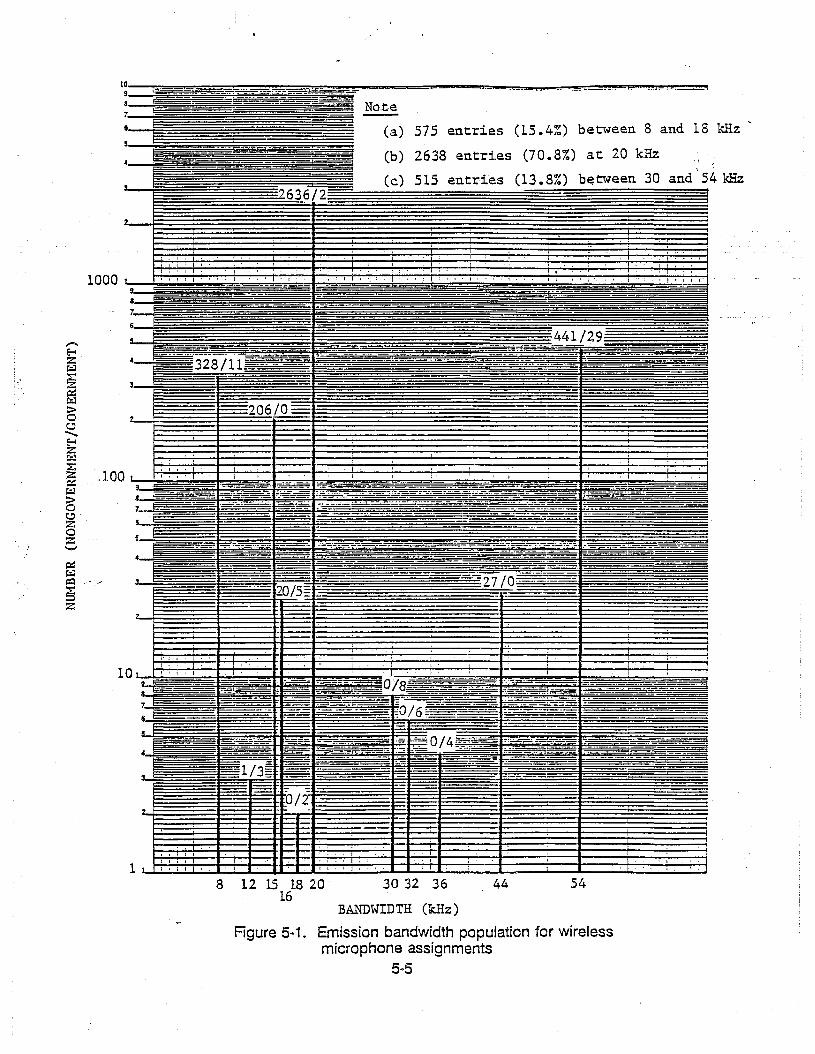
1098
7
S
Note
(a)
(b)
(c)
575 entries (15.4%) between 8 and 18 kHz
2638 entries (70.8%) at 20 kHz
515 en,tries (13 .8%) b~tween 30 and 54 kHzI
"I, i I
8 12 15 18 2016
I,
30 32 36 44 54
BANDWIDTH (kHz)
Figure 5-1. Emission bandwidth population for wirelessmicrophone assignments
5-5

-------~-~
A more spectrally efficient arrangement would result from having distinct channelbandwidths, and making bandwidth-selective assignments accordingly. For example, mostmicrophone channels could be split into two 27 kHz channels that would support most cif themicrophone emissions (20 kHz or less), while a few 54 kHz channels would remain to supportthe wideband emissions (one or two would suffice statistically).
The other' modification required would be to tighten the drift tolerance of the microphoneemissions. The current regulations limit the emissions to be within ± 32.5 kHz of their assignedfrequencies, which represents a ± 5.5 kHz frequency drift limit since a 54 kHz bandWidth isallowed. This limit is intended to maintain the microphone emissions within the hydro blockumbrella span up to the edges (see Figure 3-1). However, such tolerance also implies a VHFfrequency stability of about 30 ppm (30 x 10"6) which can be improved.
A ± 5.5 kHz drift would create a 31 kHz bandwidth span to be provided for the 20 kHzpredominant emission bandwidth of the wireless microphones. For example, this tolerancewould have to be tightened to ±3.5 kHz to limit the span to 27 kHz (split-channel) for the 20 kHzor less emission bandwidths. This would represent a VHF frequency stability of about 20 ppm(20 x 10.6) which is certainly feasible.
Another spectrally efficient arrangement would be to preserve the existing centerfrequencies of the wireless microphones, but narrowband most of the channels instead ofsplittiflg them. For example, a 25 kHz channel bandwidth would still support most of themicrophone emissions (20 kHz or less), and only require a ±2.5 kHz drift limit which representsabout 15 ppm (15 x 10.6) frequency stability (also feasible). \
Moreover, a third 25 kHz microphone channel can then be added and centered betweenthe two 25 kHz narrowband microphone channels inside a hydro block, while also providing a5 kHz guard band between the central channel and its two adjacent channels. A hydro blockwould support three 25 kHz channels instead of four 27 kHz channels, but there would be noneed to shift the current microphone channel frequencies. Only the new central frequency wouldhave to be added as an allotted channel inside each block.
The possibility of narrowbanding all wireless microphone channels, instead of preservingsome 54 kHz channels, is another alternative approach. Each hydro bloc;* would support three25 kHz channels, while preserving the current channel frequencies and adding the central one.The wideband microphone assignments would still be allowed in the current channel frequenciesand the central one, and distributed in all the hydro blocks as presently done so that bandwidthselective assignments are not required.
The fact that most microphone emissions are much narrower than their 54 kHz allowedbandwidth also implies that overspan is being provided by the hydro block umbrella to most
5-6

microphones for the sake of a few. Even if a ±5.5 kHz drift is assumed, most of the microphoneemissions need no more than 31 kHz span, yet 63 kHz span per channel is being provided toaccommodate the few wider microphones.
This span scenario is not only spectrally inefficient, but it is also dangerous since anyreduction in the hydro block span (e.g., hydrologic narrowbanding or relocating) automaticallyleaves some microphones unblocked. The channeling plan alternatives just presented for thewireless microphones would feature better control potential, since the predominantly narrowermicrophones would have more channel options, and the fewer wideband microphones could belumped together if necessary.
5-7


SECTION 6
HYDROLOGIC OPERATIONS: FLASH FLOOD WATCH AND WARNING SYSTEMS
HYDROLOGIC OPERATIONS OVERVIEW
Hydrologic operations presently conducted by government and sponsorednongovernment agencies represent a valuable nationwide service provided to state and localcommunities. These operations support environmental monitoring and forecasting, flood watchand warning, nuclear and fossil plants, stream and water analysis, etc. The community impactcan. be critical since the service outcome includes flash flood alarms, disaster prevention andcontrol, safety-of-Iife decisions, etc.
Hydrologic networks serving state and local communities have evolved into wellstructured configurations that efficiently utilize the hydrologic channels and the communityresources. The hydrologic channels support remote sites, repeater stations, operation centers,backbone nodes, etc., while the community resources augment the network coverage or serviceapplication through other available communication (e.g., microwave links, telephone lines) orprocessing (e.g., computer facilities, modem interfaces) capabilities.
The majority of the hydrologic operations correspond to flash flood watch (forecasting) andwarning (alarm) systems. The hydrologic networks involved typically have state (e.g., east coast)or local (e.g., west coast) configurations, and the present trends are towards integration ofexisting networks and service expansion to central regions, besides extending specific networksto meet community needs. There are many common elements that motivate a substantialnetwork integration potential, but also some differences that will require effective coordinationto avoid independent developments and ramifications.
Hydrologic user groups exist and meet regUlarly, with new technical standards, operationlogistics and hydrologic applications emerging and proliferating to create new emissionspecifications, channel usage, and equipment requirements. Hydrologic equipmentmanufacturers and market representatives currently implement and distribute a variety of noveldesigns that enhance the throughput capabilities (higher data rates, multichannel operation) andthe application scope (multiple parameter sensors, hybril:::f data rate support). The hydrologicoperations scenario is presently in a dynamic state and the forthcoming status accommodationcan have an impact on spectrum management concerns.
Hydrologic operations presently rely on the VHF and UHF hydrologic channels to supportterrestrial data collection and data/voice communication links. Other alternatives such assatellite or meteor-burst communication links have been found to be incompatible with the
6-1

low-power transmitter stations and real-time information transfer requirements of the currenthydrologic operations. The modification of the hydrologic equipment to use these other linkswould not be cost-effective and would require a total revision of most system specificationsand/or operation logistics, besides massive station equipment replacement.
NATIONAL WEATHER SERVICE (NWS)
NWS represents the Federal Government authority for functions relating to flood warnings,as mandated by Congress. In particular, the NWS hydrology program has as its primaryobjective to mitigate the loss of life and property damages by timely river and flood forecasts andwarnings. The operations include "flash flood watch" to inform the public via state/local agenciesof troublesome hydrological and meteorological conditions developing in designated areas, and"flash flood warning" to manage imminent or occurring flood conditions that require immediateaction.
The NWS flood warning system is spread nationwide, with all states having localcoordination or representatives as illustrated in Figure 6-1. A typical interaction between NWS,
. the local facilities and the public is shown in Figure 6-2, with the ground observation datarepresenting the critical source of information for flood warnings. The use of geosynchronoussatellite data would not be timely enough to replace the ground observations, based on theexisting capabilities without excessive 90st modifications. For example, the satellite informationwould be distributed with a 2 to 4 hour delay, in contrast to the is-minute updates beinggenerated by the existing network links, with cost effective adaptations.
The flood watch and warning operations include automated observation sensors, manualreports, data/voice communication links, automated data collection and processing, forecastingsoftware, and alarm distribution systems. These operations support the original flash flood alarmsystems, as well as the new Integrated Flood Observing and Warning Systems (IFLOWS) andAutomated Local Evaluation in Real Time (ALERT) Systems. An early local alarm systeminstallation is shown in Figure 6-3, with a river station sensor automatically detecting the criticalflood level to trigger the community alarm.
INTEGRATED FLOOD OBSERVING AND WARNING SYSTEM (IFLOWS)
IFLOWS has operated since 1979 as a cooperative venture of the Federal Governmentwith state/local governments to support effective networks for flash flood forecasting, warning,and management. The Federal Government provides initial funding and continuing technicaladvice for the network expansion to serve new communities, who share the development costswith real up-front monies on a 50% basis and are fully responsible for maintenance thereafter.
6-2

m•c.:>
Ir r·····~··· ~ . ..
i " . ~ <' . (' \......... ~..: . 1 ,. .......-4 . ~,~ .•,.'(, •.• ' ... - • Blsmarck~ ... '. ,
. 1 I. ...* lI' lis \, , _ ..•• r~ )'. • M ""PO " . ,. '..., I r' }' !" .. ,- . I *Porll.lnd',. . .' . . ... ...1.... ... ..:.... .*. . ." .~, ...... .,,' .. ":.f. . . \ . 'j'. '," :'.,... . .' '" • ..' "'. • •••"" ".J I .:.' .•-J0*J'n/. .
. ,r .. " .., _~"... .... '. "'" .. ~*Portland. . ..... , 1~1/ '. 'l:':': .,'.:.1. :: ". "louK fall- * "':. ""'f If" • \. * Ann AIOOI ._ hullalo a,' _:.... ~. ~ ., 80SIon. .. .".... "...o, " •• • ........ .o,. • , ~" ' -.;'.: '*~se t.· '. ~ ,'..... 'r~ .,'.. ." DesMolnes ·b'... ~'''''*'' ".~:,"J""-'" ;.~ .". '. . .':... ·'h·f_,.. . . I.....""',J. '. _" .• ' ..• 'r ," .... ~. - ' .. I ..-. '. . . * ,. ""'V" '11-«''''· .' .-... . . . t-o, ". . '.. ,'. '"". , o' .. , o'. '_.. .. . .. .. .. "'. " .. ,••~. ..... .•.Choy '.'. ". \ .....". ,. .,. '." "',.,,, . II...",,,. •". "." .,..... . . .. .. .. .'. .'. . . ',;, . " . ,... '., .
I . • * 1 [I .... .,. r"" .,." .' ., ,,, c.... .. . "•..~ '", I' ,.;.;. .; .}" :'.. ~., .';." ., :.'. ,. .' _ y' . l' :.' ulal...,~...... ,~ . I V(aSlllnglon
. . . '..•,., ',', .....h CIIy, ',. . *....., * . . . .,I.. h,".'.". .*,,,,,.. ". ..,' ,., "," ".,' '. "'<>, .. I",','\'· } ..,. .- ..... \; ;., (•. I ..~\.; :. " \J:;~'* ':":'. ..0<:1;;:"" .
• .,.. .. '. '. • "o, . .. .• , J'"........ _.... .••." .." I" I ,., 1... . c__,.. .. ...... "" , ,. L.....".... , .,._..... ,._ .'0'..' ... '1', . .\FllOtlsto .. , L ~.' .._..... '~' :.1. I,L.~:.>.,,- : . \ ~''''<'''''\'' ./('~ .~ ~ :' ~". '*RalllighIn "(" ." .-'1. • '. • .... ··l . . t .. Is .. ........... ~.'
. . " , ; ..'. ..... •.. IlOU_ oJ. ~'\.'; •. ; .. .. .... * Oklahoma CItV • I' ' . •• . • '" .... ,..•.• , ". .. '\..• .•.•.• .' . l ... Roc o' , to' A .... ;' . ,.1. ~ .' '~:,Albuquelqull .- 6.4.\.~ .. ..;,..: ••_ ~ :"lj:' :1""';]'::' ,.
. '! .•. '. • "'..... o' L__ •.'.' :-!'" . , ~. ..............* los Angeles '. . ... t».- ....; • . . : •••• f'::' WOlt')'''''' -::-.. , • .;' mlogham •f; '. ,' "1' u"""n... '. . ' .• '. .... '. kso f"" . I' .
\
" '. . .' ac n' \,,~, .;...... <, .. .... • .' . ;.....'-'....,.....---- ~. .'. '-\ .' '.'," :. • of::'.:. "." \,r:~ ..'):::':'-
\ . '. ': • UOus1oo ..... : ~: Uew Ollcans ."'1. ""'" ' .." \~tMb \~M.~
.Puerto Rico
San Juant ..~ ':'~~ :. -'0-
Figure 6-1. NWS nationwide coverage
location of Warning PreparednessMeteorologists (WPM) and Focal Points
l~gend
• DPM (Disaster Prepared Meteorologist)
* focal PolnllPlOgram Leader

m1.
RAINFAll AND STREAMflOW:MEASUREMENTS AND ODSERVJ\TIONS..
«IIt:o0,pra~aJUl
..c[fNili!!l, 0 t
JpllOl ~I tJw~l.. --1t_oeAL cool Oo!g
-SatelliteImoglrlf .~ t -,-- [pUBLIC OfflaAL~flAOIO ."un TELEVISION)
~
IPU~t:'C ..NOTle.;)
Figure 6-2. NWS community interaction example

0)I
01
POLICE on flllF.DISPATCII CEurEn
Up In Hi mllos poworod hy hnllollos \ Any dlslmH"lO hV lolophono-. ~~. ~
t=L---------.JI;J----j"", .....----.~~ ~L
.r. HIVEn 9TATIOti ItlTEnUEIlIA.TE ALAnULlEU30n BlAliON WlTIl
lElEPllONE ANDCniTICAL WAlEn LEVEL rOWEn SEflVICE
UOHMAL BTHEAM LEVEL
Figure 6-3. illustration of local flash flood alarm Ins~allatlon
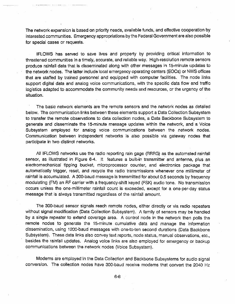
The network expansion is based on priority needs, available funds, and effective cooperation byinterested communities. Emergency appropriations by the Federal Government are also possiblefor special cases or requests.
IFLOWS has served to save lives and property by providing critical information tothreatened communities in a timely, accurate, and reliable way. High-resolution remote sensorsproduce rainfall data that is disseminated along with other messages in 15-minute updates tothe network nodes. The latter include local emergency operating centers (EOCs) or NWS officesthat are staffed by trained personnel and equipped with computer facilities. The node linkssupport digital data and analog voice communications, with the specific data flow and trafficlogistics adapted to accommodate the community needs and resources, or the urgency of thesituation.
The basic network elements are the remote sensors and the network nodes as detailedbelow. The communication links between these elements support a Data Collection Subsystemto transfer the remote observations to data collection nodes, a Data Backbone Subsystem togenerate and disseminate the 15-minute message updates within the network, and a VoiceSubsystem employed for analog voice communications between the network nodes.Communication between independent networks is also possible via gateway nodes thatparticipate in two distinct networks.
All IFLOWS networks use the radio reporting rain gage (RRRG) a~ the automated rainfallsensor, as illustrated in Figure 6-4. It features a built-in transmitter and antenna, plus anelectromechanical tipping bucket, microprocessor counter, and electronics package thatautomatically trigger, reset, and recycle the radio transmissions whenever one millimeter ofrainfall is accumulated. A 300-baud message is transmitted for about 0.5 seconds by frequencymodulating (FM) an RF carrier with a frequency-shift keyed (FSK) audio tone. No transmissionoccurs unless the one-millimeter rainfall count is exceeded, except for a one-per-day statusmessage that is always transmitted regardless of the rainfall amount.
The 300-baud sensor signals reach remote nodes, either directly or via radio repeaterswithout signal modification (Data Collection Subsystem). A family of sensors may be handledby a single repeater to extend coverage area. A control node in the network then polls theremote nodes to generate the 15-minute cumulative data and manage the informationdissemination, using 1200-baud messages with one-to-ten second durations (Data BackboneSubsystem). These data links also convey text reports, node status, manual observations, etc.,besides the rainfall updates. Analog voice links are also employed for emergency or backupcommunications between the network nodes (Voice Subsystem).
Modems are employed in the Data Collection and Backbone Subsystems for audio signalconversion. The collection nodes have 300-baud receive modems that convert the 2040 Hz
6-6

8attery CompartmentCcndensatienC~arnber
-1...,r...-..
•=....-
..-
l-- Antanna·
4
,--!! :.• :4• : I_:-....::~l Nylen Lrmng Repe
! ~~l1 : I- ..• ••; ~h~:~1~1_' Signa! 1.Nire
~ ~~;; 1.f~ HI:',. ,.,1'------- Antenna HireIt ~~- .,tf • •:: :\l! {1,., :.i /_-- Gtcund Surface1l:1 ,/- 's'-_~~-...~--
-~---~:::::»,..f~Il'""'OOoi-;r~~\_{ ~~D' ~_~:'_'-_0_""_'t' • Reck and C,:mc=ete FiiI
, 0 "",,0 l Eecenic Pad<age
1:;1 a j 0 ~I(D~-- .')r
f. _ ....2..:... _l_ Ip J:.-.:O;....;... _
'0 '....- <:::) ~"- --
Figure 6-4. Radio reporting rain gage
6~7

keyed tone into a binary RS-232C digital signal, as well as 1200-baud transmit/receive modemsthat can operate at various audio frequencies (600 Hz, 1080 Hz, 1560 Hz, 2520 Hz) for thebackbone communications and multiplexingo Voice signals can also be transmitted or receivedby a collection node for backbone communicationso
The radio frequencies reserved as hydrologic channels by the Federal Government areregularly employed in the IFLOWS links, including simultaneous usage of distinct channels inthe same network as illustrated in Figure 6-50 These channels are reliable for the Data CollectionSubsystem, which has prompted the commercial development and availability of RRRGs in thesebands. The early RRRGs had limited address capacity (100 IDs per frequency per coveragearea) so that more than one channel could be employed in the Data Collection Subsystem undercertain coverage overlap conditions. The present trend is to use a single channel for all datacollection links as shown in Figure 6-5.
The Data Backbone and Voice Subsystems use a combination of the hydrologic channelsand local/state microwave radio links, because the shannels become limited over long distancesor rugged terrain (e.go, typical VHF links are limited to 50 miles). Satellite radio or telephonelines can also be used in the Data Backbone and Voice Subsystems to provide links whenmicrowave radio is unavailable. An example of network usage of hydro channels, microwavelinks, and telephone lines is shown in Figure 6-60 Typical design goals are a 20 dB or greaterperformance margin for each end-to-end path to support a 90% communications reliability.
AUTOMATED EVALUATION IN REAL TIME (ALERT)
ALERT systems perform the same flash flood functions and rely on the same networkoperations and communication subsystems as IFLOWS with some differences. ALERT isessentially concentrated in the West Coast (California) and spreading into the midwest states(Oklahoma, Texas), whereas IFLOWS are in the East Coast states. ALERT networks mainlyserve counties or cities due to the wide state dimensions, whereas IFLOWS networks serve astate or neighboring states.
ALERT also employs the same equipment as IFLOWS for the radio reporting rain gage,data collection or backbone communications, voice communications, etc. However, ALERTgages are also being routinely equipped with additional analog measurement sensors (windspeed or direction, solar radiation, temperature, relative humidity, barometric pressure). Theanalog sensor data is encoded and transmitted along with the rainfall data on preset timeintervals. The sensor data can be sent regularly or only if it varies beyond certain presetpercentageso
6-8

V llashville tillS
'frJ-CJ.t'esmm
AshevilleNUS
Holston 'I\~Htn. "'0 ~
I' fbo1: ·h.~.~
4 gages
I> I]I .- ~~~.~Ogageu
<°40 }flJ~. 1I~
1/1') ·O.;J'
"'0 ·s'10 ~!r~
.yo?' .~
./'>0
..?o;'-J°oo .I. (~....~ :.;-
~{i 't170.275 Imz
'56D 112:
'"'
..""I,\w·
,,'J'"\I.).'l- ~..
\. (. bl.)\.)
1;'0
JS~J<so J. J~/,
'T~ ~
"'easerKllob
01"\tP
• ~f},~ ~Al::)· I<P
'\.\ '\.t-j
Knoxville 'IVA
Knoxvlile Ims
II gages
./.>./020 ' oJ:
110 0,~(~
~ tl~~g~~O,OC-
r;.
o 2 gages
- IN:l, JJa00l"'l~·0
ON"-r--f
meb
Figure 6-6. Tennesseo/Norlh Carolina 'FLOWS COtntnulllcalions Network

D!smal MIn
EOC
VUF RADIO PATH
STATE POLICE MICROWAVE SYSTEM
= TELEPHONE LINE
ROANOKE WSOWhile Top Min
GRAYSON EOC
EOC
RICHMOND OEESPoor MIn
Sl1'iTIl EOC .--... u ......,"".L J, :CARROLL EOC '--I .' ..-/
1,1 mms ../
\ , , PULASKI EOC 8
\' .'"\~". l I ,I' \ RIClIHOND HSO" , , HYTIIE EOC a '
~_..- ?[~]", \ ,EOC.
\
""
TAZEWELL EOC
~.
BUCHANAN EOC
•SCOTT EOC
DICKENSON EOC
WIS~ I'"~L' IIlgh t<nob
•TRI-CITIES EOC
Ll~E EOC
Q)I
-"o
Figure 6-6. Virginia IFLOWS Communications Links
'll
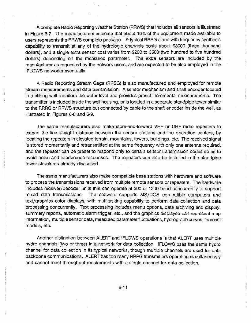
A complete Radio Reporting Weather Station (RRWS) that includes all sensors is illustratedin Figure "6-7. The manufacturers estimate that about 10% of the equipment made available tousers represents the RRWS complete package. A typical RRRG alone with frequency synthesiscapability to transmit at any of the hydrologic channels costs about $3000 (three thousanddollars), and a single extra sensorcost varies from.$200 to $500 (two hundred to five hundreddollars) depending on the measured parameter. The extra sensors are included by themanufacturer as requested by the network users, and are expected to be also employed in theIFLOWS networks eventually.
A Radio Reporting Stream Gage (RRSG) is also manufactured and employed for remotestream measurements and data transmission. A sensor mechanism and shaft encoder locatedin a stilling well monitors the water level and provides preset incremental measurements. Thetransmitter is included inside the well housing, or is iocated in a separate standpipe tower similarto the RRRG or RRWS structure but connected by cable to the shaft encoder inside the well, asillustrated in Figures 6-8 and 6-9.
The same man~!acturers also make store-and-forward VHF or UHF radio repeaters toextend the line-of-sight distance between the sensor stations and the operation centers, bylocating the repeaters in elevated terrain, mountains, towers, buildings, etc. The received signalis stored momentarily and retransmitted at the same frequency with only one antenna required,and the repeater can be preset to respond only to certain sensor transmission co~es so as toavoid noise and interference responses. The repeaters can also be installed in the standpipetower structures already discussed.
The same manufacturers also make compatible base stations with hardware and softwareto process the transmissions received from multiple remote sensors or repeaters. The hardwareincludes receiver/decoder units that· can operate at 300 or 1200 baud concurrently to supportmixed data transmissions. The software supports MS/DOS compatible computers andtext/graphics color displays, with multitasking capability to .perform data collection and dataprocessing concurrently. Text processing includes menu options, data archiving and display,summary reports, automatic alarm trigger, etc., and the graphics displayed can represent mapinformation, multiple sensor data, measured parameter fluctuations, hydrograph curves, forecastmodels, etc.
Another distinction between ALERT and IFLOWS operations is that ALERT uses multiplehydro channels (two or three) in a network for data collection. IFLOWS uses the same hydrochannel for data collection in its typical networks, though multiple channels are used for databackbone communications. ALERT has too many RRPG transmitters operating simultaneouslyand cannot meet throughput requirements with a single channel for data collection.
6-11

'. ; .~ •.
TIpping Bucket
.~i"
/ ////// ",.
Data Transmitterand BarometerPressure Sensor
Figure 6-7. Radio reporting weather station
6-12

Data Tn:msmitter
-Shaft Encoder
Figure 6-8. Radio reporting stream gage with internal transmitter
6-13
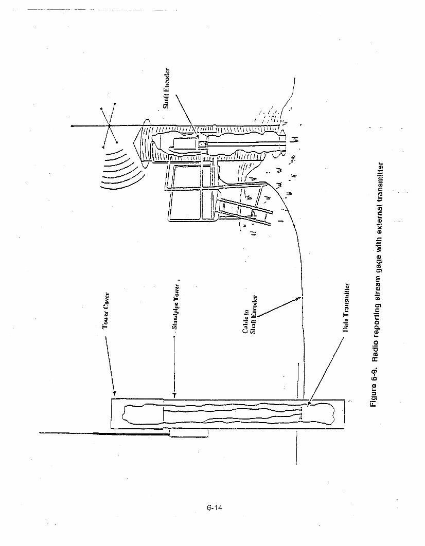
'-oQ.CD>-o
"C~c:
t : ~.t=:: ~=====?:-;=(:JIe
6-14

The same throughput limitation has motivated the potential extension from 300 to 1200baud for data collection, and all ALERT RRPGs are now being built with a switch to handle bothmodes. Both ALERT and IFLOWS are expected to support 1200-baud data collection as astandard operation in the near future, particularly considering that this rate is supported by thedata backbone communications.
The backbone dissemination in ALERT apparently relies more on telephone lines than inmicrowave links as IFLOWS does. Again, there are no universal link procedures for databackbone communications, which adapt according to the community needs and resources.ALERT does have a standards committee that meets quarterly and has special conferences inCalifornia. They set the data format and operation standards, support network linkages and usergroups, disseminate information on developments, etc.
6-15


SECTION 7
HYDROLOGIC EMISSION BANDWIDTH ANALYSIS
F2E AND F3E 16 kHz EMISSION CHARACTERISTICS
The majority of the hydrologic stations exhibit a 16 kHz emission bandwidth associated withboth the F2D digital data and F3E analog voice emissions. The analog voice basebandconsists of 3kHz single-channel speech that is applied to an FM carrier to generate the F3Eemission. A 5 kHz peak frequency deviation is employed in present systems, which results inan emission bandwidth of 16 kHz based on Carson's Rule.
The F2D emission generation consists of an FSK/FM modulation process as illustrated inFigure 7-1. The digital information data is used to shift the frequency of an audio subcarrierbetween two tone values according to the binary data state. The FSK audio baseband thusobtained is then applied as modulation to an FM carrier to generate the F2D emission. ThisFSK/FM signaling approach represents two cascaded bandwidth expansion processes relativeto the original information bandwidth.
The digital information rate is R = 300 bps or 1200 bps, which also corresponds to the firstspectral lobe of its power spectrum when NRZ rectangular pulses are used for the binarysymbols. This first spectral lobe contains 90% of the power, so that the information data ratemay be identified as the information bandwidth. The FSK subcarrier modulation creates a newand wider baseband prior to the FM carrier modulation, with a new top baseband frequency(Fm) replacing the information bandwidth (R) before modulating the carrier.
The FSK modulation parameters can be specified as the binary audio frequency states(F1,F2)' or as the subcarrier center frequency Fsc = 0.5 (F1 + F2) and the subcarrierfrequency deviation 0 sc = 0.5 I F1 - F2 1. The new baseband obtained is centered at Fsc andhas a certain bandwidth Sse determined by the FSK modulation parameters. The NTIA Manual,Annex J, has a simple formula to estimate the bandwidth (Sse) needed to preserve 99% of theFSK signal power as follows:
3.88 Dsc + 0.27 R, if 0.03 < 2Dsc S 1.0
R
2.4 Dsc + 1.0 R, if 1.0 s 2Dsc < 20
R
7-1
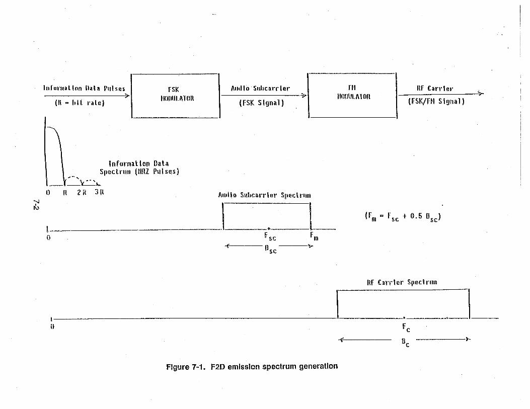
----">-1"[Urillalloll nala Plllses fSK I\udlo Suhcarrler HI Ilf CatTier
> 11011111.1\Tnn > Hnlllll.1\1on(Ii .. hlL rale) (FSK Signal) (FSK/HI S
I
InformatIon DataSpectrum (Hnl Pulses),-,
-.-\-~-"....o It 2n JR
""'"r\)
l------·o
I\udlo Suhcarrler SlledrullI
. .\. . l-Fsc Fm
( Il ?sc
(Fm ~ Fsc t 0.5 Dsc )
ItF Carrier Spcdrum
I I ._1_-a
0 Fe
f Dc ~
Figure 1~1. F2D emission spectrum generation

The top baseband modulating frequency on the FM carrier is obtained from the FSK signalbandwidth as Fm = Fsc + 0.5 Bsc = 0.5 (F1 + F2 + Bsc)' The FM carrier bandwidth (Bc) canthen be estimated for a given peak carrier deviation (Dc) as Bc = 2 (Dc + Fm) based onCarson's Rule. The bandwidth expansion factor of the total FSK/FM process relative to theoriginal information bandwidth is given by Bc/R = (Bc/Fm).· (Fm/R), as the product of the twopartial expansion factors due to the FM.and FSK modulation processes in cascade.
The modulation specifications of existing hydrologic systems are employed in TABLE 7-1to derive the FSK subcarrier baseband parameters (Bsc,Fm), and the corresponding partial andtotal bandwidth expansion factors. The results obtained can be summarized as follows:
.. The F2D emission bandwidth (Bc) is indeed about 16 kHz for both information datarates (R), even though the FSK subcarrier modulation parameters (Fsc,Dsc) and FSKsignal bandwidth (Ssc) are different.
• The top baseband frequency (Fm) of the FSK subcarrier signal approximates the 3 kHzoccupancy of analog speech for 1200 bps data, and is only slightly lower for 300 bpsdata.
• The total bandwidth expansion factor (Bc/R) of the FSK/FM process is about 50 for300 bps and 13 for 1200 bps, in order to produce the 16 kHz F2D emission bandwidth.The main distinction is in the FSK baseband expansion, with a factor (Fm/R) .of 7.6 for300 bps and 2.4 for 1200 bps, in order to approximate a 3 kHz baseband. The FMexpansion factor (Bc/Fm) is similar for both rates, since the top baseband frequency(Fm) of the FSK subcarrier signal is similar.
Measurements of the F2D emission spectrum are shown in Figure 7-2, as provided by theequipment manufacturers. The top picture corresponds to a VHF remote-sensor stationtransmitter, and the bottom picture to a VHF repeater station transmitter. Both transmittersrepresent equipment presently employed in existing hydrologic systems and operations.
BANDWIDTH CONSERVATION ALTERNATIVES
The modulation method employed in the majority of the hydrologic emissions has beenshown to consist of accepting (for voice) or creating (for data) an audio baseband (analog voicechannel, digital FSK data subcarrier), which is then applied as frequency modulation to generatethe 16 kHz F3E (FM voice) or F2D (FSK/FM data) emissions. The FSK subcarrier basebandgenerates a lowpass occupancy similar to the voice channel (2.3 kHz for 300 bps and 2.8 kHzfor 1200 bps versus 3 kHz for speech) prior to the FM carrier modulation.
7-3

TABLE 7-1
F2D MODULATION EXAMPLES
FSK AUDIO-SUBCARRIER GENERATION
Information Data Rate (R)
Binary Audio Frequencies (F1,F2)
Subcarrier Center Frequency (Fsc )
Subcarrier Peak Deviation (Dsc )
Audio Subcarrier Bandwidth (Bsc )
FM RF-CARRIER GENERATION
Carrier Modulating Frequency (Fm)
Carrier Peak Deviation (Dc)
RF Carrier Bandwidth (Be)
BANDWIDTH EXPANSION FACTORS
FSK Baseband Expansion Factor (FmiR)
FM Bandwidth Expansion Factor (Bc/Fm)
FSK/FM Bandwidth Expansion Factor (Bc/R)
300 bps
1920,2133 Hz
2026.5 Hz
106.5 Hz
492 Hz
2272.5 Hz
5000 Hz
14545 Hz
7.6
6.4
48.6
1200 bps
1200,2200 Hz
1700 Hz
500 Hz
2254 Hz
2827 Hz
5000 Hz
15654 Hz
2.4
5.5
13.2

MKR 17a.~2~~ M~=-:>~ '='a c:=m--- - -
I E~ --d~ H--H"~)wI' I t.y I I I I' X.'Wr'f. .I. I .4~... ,or 11.w~ Ir--j~
I I #JO I. '\
I.,," I"" I I I I Ic:m'"I
MAF<lE~ I I IrW',I I I I I1 7~i 224.;a MH:: r ~ \/ I I I-22J ~Ia dSm I I
I I I ~ I t I I I JI I I II I 1\ I I II I I~~/ I I I~I I I
,1 I ... 1 IJA ..';y~1· . I I I ~'~~~n Iwll"f" I P' I I I I I
• I I 1111"1'~~ .Al~Jfl'\" 1" . "Wll " J T'I
I I II
I i I I I II I I
b R~=- 1a. a c:Sm A-,I ~N 2-a c:s•
1121 C::!/
Q
C%NTa~ 17~.a24S MH:RSS aw 1 kH:
-'0 a ..cvaw 1121. kl-!:
Si2 AN 1 ~13. a kH::S",>,/P ::. a ••0:
113 c:S/
MKR 171.1a13g MH=-s. a~ dSm
I I kL1-.~"b H-fc~, ~ I I.c.Ion".l:I: i..l.. l~ n ~.:'l:..~
I I~ ~.Jn~ I tvYIM., I I I I I. I r
I I' I Ir \11 '\~ I I I IMAF<ll<E:~
1 7l j 1 "1I!2I~ fwiH:: ,~ \ I I I I-S.0!2J dSm I ,
I I I rl I f\ . I I I II, , ,
I I I II i 1\ I I '/I L_I I I f I i I \ I I I
I I I Jrf I I I y~ I, !11 ....~lA.J ••• JA ~!f'l I I I 1~I¥q)yi1"t%'I'~~ftJ· IlllJ II! .. 'I 1'Y' ! I
I I. I I I I I I II I I
I,
c::::i.Nlc:.n 1.71•.1I<I13a MH::.RES aw 1 ""H=
-<: Cl p'ava"! '113 ""M:
Si2 "'tt 1 ~:<:. Q I1H:o:,SWP ~. ia ....c:
Figure 7-2. ALERT transmitter emission spectrum: Remote Sensor Station (Top),Repeater Station (Bottom)
7·5

-----,--- - ---,~-----~-----------
The discussion that follows addresses potential modifications to these modulationprocesses towards reducing the emission bandwidths while supporting the same information rate(3 kHz speech, 300/1200 bps data). There are two basic generic approaches that should bedistinguished due to their distinct-implementation and economic implications, as follows
• Modify only the carrier modulation process while keeping the present audio basebandsintact, so that the FSK data subcarrier with its speech-like occupancy is preserved.
• Modify the carrier and/or subcarrier modulation processes, such that the preservationof the existing FSK data subcarrier or its speech-like occupancy is not required.
The first approach is only concerned with reducing the bandwidth expansion factor relativeto the present audio basebands, which is of the order of 5 to 7 with the existing FM carriermodulation. The FSK baseband expansion relative to the information data rate would bepreserved in the first approach, but could be reduced or avoided by the second approach (e.g.,eliminated if direct-carrier modulation is used for the data emissions).
A motivation for maintaining the FSK audio subcarrier generation in the hydrologic dataemissions is that the baseband modems supporting the data communications between theoperation centers and nodes are presently designed to automatically handle the FSK audiosignal and perform RS-232C standard conversions for data processing and computer interfacing.A departure from the FSK audio subcarrier approach would imply new modem implementationsto a massive extent, and perhaps new technology development based on the new modulationto be supported.
A motivation for maintaining the 300/1200 bps data transformation into a wider audiobaseband with speech-like occupancy is the present capability of using common transmit andreceive equipment to handle the voice or data emissions without distinction. If a narrowerbaseband occupancy and emission bandwidth is provided with a new data signal, then not onlynew station equipment will be required, but distinct equipment will have to be dedicated to voiceversus data support.
Such need for dual equipment would apply to the backbone links of the hydrologicnetworks, which usually handle both voice and data emissions, as indicated by the dual stationclasses and emission designators in the GMF assignments. It would also restrict some datacollection links if they have been (or will be) expanded to support voice besides data messages(e.g., emergency reports from human observers at remote sites), since new narrowband dataequipment may not accommodate a voice baseband.
7-6

CARRIER MODULATION MODIFICATION WITH FSK SUBCARRIER PRESERVATION
The simplest approach with minimum impact is to reduce the FM carrier deviation, whilepreserving the analog voice channel and digital FSK subcarrier basebands. For example, a 2to 3 kHz deviation yields a 10 to 12 kHz emission bandwidth for the 3 kHz speech basebandbased on Carson's Rule. The digital FSK subcarrier basebands would result in emissionbandwidths of 8.6 to 10.6 kHz for 300 bps, and 9.6 to 11.6 kHz for 1200 bps, with a 2 to 3 kHzFM carrier deviation.
The maximum bandwidth reduction while preserving the existing audio basebands isobtained by using SSB/AM instead of FM for the carrier modulation. The emission bandwidthwould then be approximately 3 kHz for speech, 2.8 kHz for 1200 bps data, and 2.3 kHz for 300bps data. A slight increase may occur depending on the spectral location of a pilot toneincluded in the SSB/AM signal structure. This pilot tone is a low-level signal employed toprovide amplitude or frequency references and implement receiver processing improvementsneeded to circumvent some distortion limitations of SSS/AM relative to FM 0N. Shelton, et ai,NTIA Report 84-156).
For the analog voice emissions, the bandwidth expansion factor is about 1.0 for SSB/ AM,and 3.3 to 4.0 for FM with 2 to' 3 kHz carrier deviation, which should be compared to the 5.3expansion factor that occurs with the present FM modulation parameters. For the digital dataemissions with the FSK subcarrier preserved, the bandwidth expansion factors are summarizedin TABLE 7-2 for these modulation alternatives, and should be compared to the expansionfactors of 50 (for 300 bps) or 13 (for 1200 bps) that occur with the present FSK/FM modulationparameters.
The emission bandwidth conservation provided by these modulation alternatives isaccompanied by a reduction in output performance; Le., the output signal-to-noise power ratio(SNR) in the analog voice or digital subcarrier baseband demodulated. A reduction from the5 kHz FM deviation presently employed conserves bandwidth but reduces output SNR; e.g., a2 to 3 kHz deviation is an 8.0 to 4.4 dB reduction relative to 5 kHz deviation. The use ofSSB/AM for maximum bandwidth conservation fully eliminates the FM improvement factorotherwise achieved in the output SNR performance, with the only processing gain being acompanding effect.
The output SNR degradation will affect the speech quality and the data error rate, underequivalent operational conditions (Le., same frequency band and link power bUdget). If suchdegradation results in an unacceptable performance, then an increased transmitter power,shorter links and more repeaters, or special baseband processing (e.g., speech companding,data error-correction coding) would be required while operating in the same band. For example,companded SSB/AM and 2.5 kHz deviation FM have been considered as VHF land-mobile
7-7

""",())
TABLE 1-2
EMISSION BANDWIDTH CONSERVATION AlTEANATIVESWITH FSK SUBCARRIER GENERATION PRESERVED
fM Carrier Generation Option ACSB* tlBfM (Dc;:: 2 kllz) NIlff1 (Dc := 3 kllz)
Baseband Information Data Rate (R, bps) 300 1200 300 1200 300 1200
fSK lop Baseband frequency (fm, liz) 2272.5 2827 2272.5 2827 2272.5 2827
Fmission Bandwidth (Ilct liz) 2272.5 2827 8545 9654 10545 11654
Suhcarr ier Ilasehand fxpans i on factor (fnlR) 7.6 2.4. 7.6 2.4 7.6 2.4
Carrier Modulation Expansion factor (Oc/Fm) 1.0 1.0 3.8 3.4 4.6 4.1
Total Band\'ddth Expansion Factor (llclR) 7.6 2.4 28.5 8.0 35.2 9.7
*ACSO bandwidth could be larger depending on pilot"tone location in signal structure.

alternatives to conventional 5 kHz deviation FM, and shown to compromise service quality onlyat the communication range limits (weak signal conditions degraded speech intelligibility), withSSB/AM being more affected than 2.5,kHz FM relative to 5 kHz FM £:N. Shelton, et ai, NTIAReport 84-156).
DIRECT-CARRIER MODULATION BY DATA
The existing FSK data subcarrier already features a baseband expansion factor of only 2.4at 1200 bps, which can become the data rate standard in the near future. This limits theemission bandwidth saving potential via baseband occupancy reduction, while maintaining asimple digital subcarrier modulation. For example, binary PSK with 90% power preserved wouldstill represent a baseband expansion factor of about 2.0, and would need quaternary PSK for a1.0 factor with 90% power preserved (or high-alphabet QAM for factors below unity) to getsizeable occupancy savings relative to the existing FSK subcarrier baseband.
There still would remain the bandwidth expansion factor due to a carrier modulationprocess. It is evident that if the preservation of the data subcarrier baseband with speech-likeoccupancy is negotiable, the logical direction towards bandwidth conservation is to eliminate thesubcarrier and rely on direct-carrier modulation by the data. And it should be well accepted thatthis would have strong implementation and economic repercussions due to the new transmit,receive, and modem equipment that will be needed as replacement to a massive extent.
The use of analog direct-carrier modulation by data pulses has been essentially limited toFSK in practice, with conventional discriminators employed at the receiver for the pulse traindemodulation before the digital state decisions. The emission spectrum when using rectangularpulses is similar to that obtained in digital FSK, and there are other digital direct-carriermodulations capable of producing a narrower emission bandwidth, while still maintaining theincoherent detection capability and ptoviding comparable error performance (e.g., DPSK, MSK).
The use of SSB/AM for direct-carrier modulation by data pulses would provide maximumemission bandwidth conservation, but this method is severely hindered by the large peakenvelope excursions in the modulated signal. Such envelope peaks would have to beaccommodated by the transmitter peak-power specifications to avoid saturation (clippingdistortion), and the SSB/AM peaks that occur with pulse modulation are very high comparedto speech modulation. Hence,SSB/AM has been found to be not suitable for data transmission,while remaining useful for voice communications.
With reference to digital direct-carrier modulation methods, the simpler approach is binaryPSK which requires an emission bandwidth of about twice the bit rate with 90% power preserved,e.g., 600 Hz for 300 bps and 2400 Hz for 1200 bps. The receiver could rely on differential
7-9

detection to avoid the more complex coherent detection with a tracking loop required, thoughsacrificing a 3 dB performance margin in the exchange.
Any further bandwidth reduction must be provided by using a higher digital alphabet withthe corresponding equipment complexity and error performance compromises (e.g., more signalpower is needed for the same error rate as the alphabet size increases). For example,quaternary PSK requires an emission bandwidth equal to the bit rate with 90% power preserved,and higher PSK or QAM alphabets can support smaller bandwidths by a factor of 1092M, whereM is the alphabet size (e.g., 1092M = 6 for 64 QAM).
The basic distinction in PSK versus QAM with higher alphabets is in the error rateperformance and the equipment processing requirements, since they essentially support thesame emission bandwidth for a given alphabet size. QAM has more digital detection immunitythan PSK for the same alphabet due to the joint amplitude and phase discrimination, but PSKis a constant-envelope signal (unlike QAM) plus it does not necessarily require coherentdetection (unlike QAM).
. In any case, extensive equipment modification with more complexity would be required with, higher digital modulation. Even binary PSK with its moderate bandwidth conservation would nowbe an expensive alternative, given the amount of existing FSK/FM hydrologic emissions andFSK baseband interface modems. The possible proliferation of higher digital modulation in thefuture could make such options more affordable, but there would still then remain the need fordual equipment dedication to handle data and voice transmissions differently.
BANDWIDTH ANALYSIS AND CONSERVATION SUMMARY
The 16 kHz bandwidth predominantly assigned for the F2D and F3E hydrologic emissionsis the necessary bandwidth for the modulation methods and parameter specifications employed.The 300/1200 bps data conversion to an FSK audio subcarrier baseband essentially matchesthe 3 kHz voice baseband occupancy, and'permits common station equipment employed fordata/voice communications. It also permits standard FSK modem compatibility for automateddata processing and computer interfacing in the hydrologic networks.
The use of analog narrowband technology can maintain these features while also providingnarrowband operation and bandwidth conservation. Amplitude compandored single-sideband(ACSB) and narrowband frequency modulation (NBFM) represent this analog narrowbandtechnology. The NBFM approach has minimum impact in equipment modification, since onlya reduction in the FM carrier deviation value from 5 kHz to about 3 kHz is required. Also, NBFMhas shown more performance degradation immunity than ACSB in recent experimental tests.
7-10

NBFM commercial equipment is not currently marketed In the United States for the VHFor UHF band, though it is readily available in Europe for these bands. This suggests that a fiveyear period could suffice for NBFM availability, particularly since the development of a 12.5 kHzchanneling plan for the overall VHF band is presently under consideration to resolve sharing andcongestion concerns. Also, 25 kHz FM and 12.5 kHz NBFM commercial equipment is currentlyavailable in the United States for other higher frequency bands, as discussed in the next section.
The use of direct carrier modulation for the digital data emissions has more bandwidthconservation potential, but the preservation of the FSK audio baseband would be lost thusmaking all FSK audio modems obsolete and requiring massive modem replacement. Therewould also be new and more sophisticated transmitters and receivers required in the hydrologicstations to support the data collection or backbone communications, making this option veryquestionable from cost/complexity considerations at this stage.
7-11


SECTION 8
POTENTIAL BAND RELOCATION OF HYDROLOGIC CHANNELS
HYDROLOGIC CHANNEL RELOCATION CONSIDERATIONS
The 162-174 MHz (VHF) and 406.1-420 MHz (UHF) bands are mainly allocated to .government Fixed and Mobile Services on a primary basis. The major exception (besidesfootnotes) is the 173.2-173.4 MHz portion, which is allocated to nongovernment Fixed (primarybasis) and Land Mobile (secondary basis) Services. The 406.1-410 MHz band is also allocatedto the government/nongovernment Radio Astronomy Service on a primary basis.
In particular, the VHF band has been cited as becoming congested due to proliferatingland-mobile government operations, and the possibility of using an alternate frequency band forthe Fixed Service has been proposed to alleviate the situation, (IRAC DOC. 26223/1). Themajority of the hydrologic channel assignments represents hydrologic operations andcorresponds to the Fixed Service, so that the potential relocation of hydrologic channe.ls.automatically becomes part of the issue.
The potential r~location of the VHF hydrologic channels offers two main options. One isto relocate them to the UHF band, where hydrologic technology and operation logistics is wellestablished. Another is to relocate them to'another band, in which case a purely Fixed Serviceband would be ideal. \Such a band would exhibit no spectrum sharing concerns or complexcoordination requirements to accommodate other services.
If the VHF hydrologic channels are to be relocated to a band other than the UHF band,then the potential relocation of the UHF hydrologic channels must also be considered.Otherwise, the natural trend for hydrologic users will be to relocate to the UHF band rather thanto the new band available, since the equipment availability and operation logistics are wellestablished in the UHF hydrologic channels.
It would be actually simpler to relocate the UHF hydrologic service to the VHF band thanthe reverse, since the UHF band has considerably less hydrologic assignments, and the VHFband has many more hydrologic plus interstitial channels in the hydro blocks. Moreover, thenarrowband channeling plans currently being considered for the VHF band could be used tocreate any needed bandwidth support for the narrowband relocation of the UHF hydrologicservice.
The 30·50 MHz band is another relocation alternative, since it was originally allocatedalong with the VHF and UHF bands in question for government Fixed and Mobile Service
8-1

support. This band contains various noncontiguous slots where the hydrologic channels couldbe accommodated with current (25 kHz) or narrowband (12.5 kHz) channel bandwidths, butseparated by gaps presently dedicated to nongovernment Land Mobile Service. Also, there areno specifically designated hydrologic channels in these slots, plus the system links would exhibitpropagation reliability uncertainties, besides the mutual interference potential between hydrologic(fixed) and mobile stations.
On this basis, the following potential relocation cases will be addressed in the discussionthat follows:
• VHF hydrologic service accommodation in the UHF band
• UHF hydrologic service accommodation in the VHF band
• VHF and UHF hydrolgic service accommodation in purely Fixed Service bands
VHF HYDROLOGIC CHANNEL ACCOMMODATION IN UHF BAND
The accommodation bandwidth needed by the 20 hydrologic plus 1 quasi-hydrologic VHFchannels is 525 kHz with a 25 kHz channel bandwidth, or 262.5 kHz with a 12.5 kHz channelbandwidth. The UHF hydrologic bandwidth span currently available is 225 kHz, as provided bythe eight hydrologic plus one quasi-hydrologic channels. Hence, VHF accommodation in theUHF band without a reduction in the number of channels is not possible, even when consideringa 12.5 kHz UHF hydrologic split-channel operation (Le., 18 UHF narrowband channels wouldhave to accommodate 21 VHF plus 9 UHF narrowband channels).
The accommodation of more hydrologic channels in the UHF band can be accomplishedby dedicating the 25 kHz gaps between the current neighboring hydrologic channels tohydrologic operations (Le., the gaps would become hydrologic channels). However, there areonly four such gaps, which represents 100 kHz in additional bandwidth capable of supportingonly four more 25 kHz channels or eight more 12.5 kHz channels. Moreover, these gapspresently have mobile and land-mobile assignments which would have to be grandfathered, sothat the new UHF hydrologic channels would not be fully protected for awhile.
UHF HYDROLOGIC CHANNEL ACCOMMODATION IN VHF BAND
The accommodation bandwidth needed by the eight hydrologic plus one quasi-hydrologicUHF channels is 225 kHz with a 25 kHz channel bandwidth, or 112.5 kHz with a 12.5 kHzchannel bandwidth. The VHF hydrologic bandwidth span currently available is 525 kHz, as
8-2
provided by the 21 hydrologic plus 1 quasi-hydrologic channels. There are various relocationpossibilities to be considered as follows.
A direct absorption of the 9 current UHF channels into the 21 current VHF channels maynot be desirable since VHF hydrologic.user congestion.could be created. If the 25 kHz channelbandwidths are to be preserved, it is preferable to relocate the UHF channels to the 16 VHFinterstitial channels inside the four hydro blocks, which are allowed to support emissions with16 kHz or less necessary bandwidth.· However, potential interference between the regular andinterstitial hydrologic channels can still limit the user capacity that can be accommodated. Also,the spectral congestion relative to other services in the band would remain unresolved.
The best solution for the VHF band itself consists of using 12.5 kHz hydrologic channelbandwidths, which can be provided with narrowband technology as previously discussed. The21 VHF hydrologic channels would need only 262.5 kHz of the 525 kHz currently provided, andsome of the 262.5 kHz bandwidth liberated can be used to support the nine UHF hydrologicchannels, .which would be also narrowbanded besides relocated. The 112.5 kHz bandwidthneeded for the narrowband UHF hydrologic accommodation would still leave 150 kHz of total
.bandwidth available after the narrowband relocation.
This 150 kHz total bandwidth would still be located inside the VHF hydro blocks, whichcurrently contain all the wireless microphone channels. If this 150 kHz bandwidth is used tosupport mobile or land-mobile operations, the mutual interference potential with the wirelessmicrophone operations would be enhanced. It is preferable to dedicate the 150 kHz to fixedstation operations only, and grandfather some of the Fixed Service out of other VHF or UHFband portions then left open for Mobile or Land Mobile Service exclusively. This would helpalleviate congestion, and the hydrologic community would also profit since the Fixed Servicededication can be used for hydrologic stations as well.
HYDROLOGIC CHANNEL ACCOMMODATION IN PURELY FIXED BANDS
The National Table of Frequency Allocations of the NTIA Manual was investigated forpurely Fixed Service bands as potential alternate bands for the hydrologic channels. A list ofthese bands with their corresponding bandwidth span is shown in TABLE 8-1, The top groupconsists of bands that are allocated to government and nongovernment on a primary basis. Thebottom group consists of bands that are allocated only to nongovernment on a primary basis,and any government use of these bands is specified by footnotes as summarized in TABLE 82.
A 525 kHz bandwidth is needed to accommodate the VHF hydrologic channels whilemaintaining their 25 kHz bandwidth allocation. There are four bands in the top group of TABLE
8-3
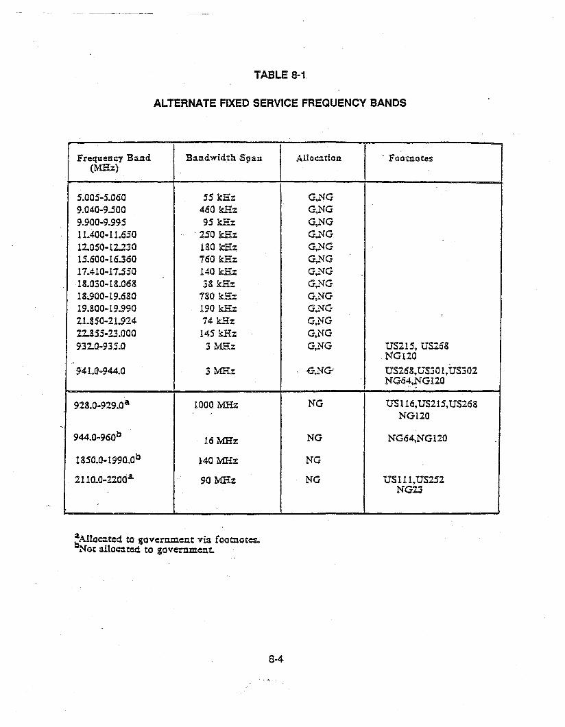
TABLE 8-1
ALTERNATE FIXED SERVICE FREQUENCY BANDS
Frequency B~.l1d B:l.l1dwidth Span Alloation . Footnotes(MHz)
5.005-5.060 55 kHz G.NG9.040-9.500 460 kHz G,NG9.900-9.995 95 kHz G.NG11.400-11.630 . 250 kHz G...'l'G12.050-12..230 180 kHz G,NG15.600-16.360 160 kHz G,NG17.410-17.530 140 kHz G...'l'G18.030-18.068 38 kHz G,NG18.900-19.680 780 k.E::z: G,NG19.800-19.990 190 kHz G.NG21.850-11..924 74 kHz G,NG22.853-23.000 145 kHz G.NG932.0-935.0 3 MHz G,NG U5215, US268
NG120
941.0-944.0 3 MHz: , -G.NG' U5268,U530 I,U5302N06~.NG120
,
928.0-929.0a 1000 MHz NG U5116,U5215,U5268NG120
944.0-960° 16 MHz NG NG64.NG120
1850.0-1990.0° ~40 MHz NG
2IlO.O-nOaa. 90 MHz NG U5111,U5252NG23
~AIIOC:U:=d to government via. footnotes..Not :tlloc:J.ted to government.
8·4

TABLE 8-2(page 1 of 2)
FOOTNOTES TO THE FIXED SERVICE FREQUENCY BANDS
Government (G) Footnote
G2-····ln the bands 216-225,. 420-450 (except as provided by US217), 890-902, 928-942,1300-1400, 2300-2450, 2700-2900, 5650-5925, and 9000-9200 MHz, the Governmentradiolocation is limited to the military services.
US111--ln the band 1990-2120 MHz, Government space research earth stations may beauthorized to use specific frequencies at specific locations for earth-to-spacetransmissions. Such authorizations shall be secondary to non-Government use of thisband and sUbject to such other conditions as may be applied on a case-by-case basis.Corpus Christi, Tex., 27 0 39' N 09r 23' W.'Fairbanks,. Alaska, 64 0 59' N 14r 53' W.Goldstone, Calit, 35 0 18' N 116 0 54' W.Greenbelt, Md., 39 0 00' N 076 0 50' W.Guam, Mariana Is., 13 0 19' N 144 0 44' E.Kauai, Hawaii, 22 0 08' N 159 0 40' W.Merritt Is., Fla., 28 0 29' N 080 0 35' W.Rosman, N.C., 35 0 12' N 082 0 52' W.
US116-·ln the bands 890-902 MHz, 928-932 MHz, and 935-941 MHz, no new assignments arei to be made to Government radio stations after July 10, 1970, except, on a case-by-.case
basis,. to experimental stations and to additional stations of existing networks in Alaska.Government assignments existing prior to July 10, 1970 to stations in Alaska may becontinued. All other existing Government assignments shall be on a secondary basis tostations in the non·Government land mobile service and shall be subject to adjustmentor removal from the bands 890-902 MHz, 928-932 MHz, and 935-941 MHz, at the requestof the FCC.
US215-·Emissions from microwave ovens, manufactured on and after January 1, 1980, foroperation on the frequency 915 MHz must be confined within the band 902-928 MHz.Emission~ from microwave ovens manufactured prior to January 1, 1980, for operationon the frequency 915 MHz must be confined within the band 902-940 MHz.Radiocommunications services operating within the band 928-940 MHz must accept any
.. harmful interference that may be experienced from the operation of microwave ovensmanufactured before January 1, 1980.
8-5

TABLE 8-2(page 2 01.2)
US252--The bands 2110-2120 and 7145-7190 MHz, 34.2-34.7 GHz are also allocated for earth~
to-space transmissions in the Space Research Service, limited to deep spacecommunications at Goldstone, California.
US268--The bands 890-902 MHz and 928-942 MHz are also allocated to the radiolocation servicefor Government ship stations (off-shore ocean areas) on the condition that harmfulinterference is not caused to non-Government land mobile stations. The provisions offootnote US116 apply.
US301--Except as provided in US302, broadcast auxiliary stations licensed as of November 21,1984, to operate in the band 942-944 MHz may continue to operate on a co-equal primarybasis to other stations and services operating in the band in accordance with the Tableof Frequency Allocations.
Non-Government (NG) Footnotes
US302--The band 942-944 MHz in Puerto Rico is allocated as an alternative allocation to thefixed service for broadcast auxiliary stations only.
NG23---Frequencies in the band 2100-2200 MHz may also be assigned to stations in the. international fixed public. radio service located south of 25°30' north latitude in the Stateof Florida and in U.S. Possessions in the Caribbean area, provided, however, no new
assignments in the band 2150-2162 MHz will be made to such stations after February25,1974.
NG64---Broadcast auxiliary stations licensed as of July 10, 1970, to operate in the frequencyband 942-947 MHz may continue to so operate pending a decision as to their dispositionthrough a future rule making procedure.
NG120--Frequencies in the 928-960 MHz band may be assigned for multiple address systemsand mobile operations on a primary basis as specified in part 94.
8-6

8-1 that could potentially support this requirement (15.6-16.36 MHz, 18.9-19.68 MHz, 932-935MHz, 941-944 MHz). The possible relocation while also narrowbanding the VHF hydrologicchannels should be considered as well. The use of 12.5 kHz hydrologic channels would requireonly a 262.5 kHz total bandwidth, and one more frequency band (9.04-9.5 MHz) in the top groupof TABLE 8-1 is added as a potential· candidate.
If the eight hydrologic and one quasi-hydrologic UHF channels are also to be relocated,then an additional 225 kHz (25 kHz channels) or 112.5·kHz (12.5 kHz channels) is needed. Thenew totals of 750 MHz (25 kHz channels) or 375 kHz (12.5 kHz channels) can still beaccommodated by the aforesaid bands for their respective cases, though some of the lowerfrequency bands would need most of their span and other services could be compromised. Thelower frequency bands would also imply large antennas and propagation uncertainties, besideslimited growth capacity.
The 932-935 MHz and 941-944 MHz bands do not have .such limitations, plus they havebeen recently reserved for Fixed Service, and they are essentially unpopulated at present sincethey were a part of a nongovernment land-mobile reserve band. In particular, the 932-932.5 MHz
r'< and 941-941;5 MHz portions of these bands have been selected to support single-channel, pointto-multipoint links, which is compatible with the hydrologic operations and networkconfigurations. There is only one assignment in Alaska and at the 941 MHz edge as of August10, 1989, for these two subbands.
Each of these two subbands (932-932.5 MHz, 941-941.5 MHz) provides a 500 kHzbandwidth span that could accommodate the 750 kHz jointly (25 kHz channels) or the 375 kHzindividually (12.5 kHz channels). However, the hydrologic users would not have exclusivelydedicated channels since. the band is shared, though the hydrologic operations would still bea primary protected service once assigned.. The use of these subbands is expected to proliferaterapidly, so any hydrologic relocation would have to occur as soon as possible. Otherwise, thereis no guarantee that the hydrologic bandwidth required will be made available, since there areno designated (existing or planned) hydrologic channels in these bands.
Some FM microwave station equipment for point-to-multipoint links in this band is alreadybeing marketed with FCC-type approval to support either 25 kHz channels (5 kHz FM deviation)or 12.5 kHz channels (3 kHz FM deviation). The necessary bandwidth and emission designatorssupported include 16 kHz for F2D emissions and 20 kHz for F3E emissions with a 25kHzchannel bandwidth, as well as 11 kHz for F2D emissions and 12.5 kHz for F3E emissions witha 12.5 kHz channel bandwidth. This implies that the FSK audio subcarrier baseband in thehydrologic emissions can be maintained, along with all the FSK audio modems presentlyemployed in the hydrologic networks. In fact, the FSK audio modem support is one of thefeatures being emphasized by the microwave equipment manufacturers.
8-7

BAND RELOCATION AND CHANNELING PLAN ASSESSMEt4T
The VHF to UHF hydrologic relocation is not desirable, since there are not enough UHF'channels even if narrowband split-channels are considered to double the UHF user capacity.Conversely, the UHF to VHF hydrologic relocation is feasible, particularly if a 12.5 kHznarrowband channeling plan is established for the VHF band. The UHF hydrologic channelscan be easily accommodated with 12.5 kHz VHF channel bandwidths, while still leaving 150 kHzextra total bandwidth available, and preserving the wireless microphone compatibility potentialby judicious use of this 150 kHz bandwidth (e.g., fixed service dedication).
The relocation of the UHF hydrologic channels is also a good idea because the UHFhydrologic channeling plan is not very efficient by itself. The UHF hydrologic channels do notform contiguous blocks (unlike the VHF channels), with the exception of one block of threechannels due to the UHF quasi-hydrologic channel location. This implies that the current UHFplan only has two interstitial channels inside one hydro block, in contrast to 16 total VHFinterstitial channels inside the four hydro blocks.
Hence; the interstitial channels neighboring a hydrologic channel in the UHF band alsohave a nonhydrologic channel neighbor (with two exceptions), whereas there are 16 VHFinterstitial channels with hydrologic channels as neighbors on both sides. The VHF hydro blocksessentially limit nonhydrologic interference potential to many interstitial channels via thecontiguous channel arrangement, whereas the UHF hydrologic plan leaves all but two interstitialchannels open to potential adjacent nonhydrologic interference. The lack of contiguoushydrologic channels is a major drawback for interstitial hydrologic operations in the UHF band.
Ifan overall 12.5 kHz channeling plan is to be implemented in the VHF band, the interstitial. channels can become the new channels (center frequencies) being added. The current channels
(center frequencies) would then also remain, and only their channel bandwidths would need tobe halved. In partiCUlar, the VHF hydrologic channels would preserve their center frequenciesin narrowband operation, and some of the current interstitial channels could be used to supportthe narrowband UHF hydrologic relocation. A total of 36 narrowband channels would beprovided. as shown in Figure 8-1, so that a surplus of narrowband channels would still beavailable inside the current hydro blocks, after the 21 VHF and 9 UHF narrowband hydrologicreaccommodation.
An alternative 12.5 kHz VHF channeling plan would have the current channels split in themiddle to form two new center frequencies. The VHF hydrologic channels would then need tobe shifted 6.25 kHz besides narrowbanded, and the other half of a split-channel could be usedto support the narrowband UHF hydrologic relocation. A total of 40 narrowband channels wouldbe prOVided as shown in Figure 8-2, .so that a surplus of narrowband channels would still be

available inside the hydro blocks, after the 21 VHF and 9 UHF narrowband hydrologicreaccommodation.
Both these VHF narrowband ch~nn~ling plan options could,still maintain most (Figure 81) or all (Figure 8-2) of the wireless microphone block umbrella by dedicating the surpluschannels to All· Government Agencies (AGA) for fixed service·operations. The mitigation of themutual interference potential between the wireless microphone and mobile/land"-mobileoperations in the band would then be preserved.
Finally, the joint VHF plus UHF relocation to another band has the 932-932.5 MHz and941-941.5 MHz microwave bands as main candidates. They are new bands dedicated to onlysingle-channel, point-to-multipoint, Fixed Service operations (IRAG Doc. 26332 (Agenda) andSecond Order General Docket 82-243 (FCC), February 28, 1989) and there is equipmentcommercially available to support the F2D/F3E hydrologic emissions with either 25 kHz or12.5 kHz channeling plans. However, a drawback is that they are for sharedgovernment/nongovernment support, so that there are no channels specifically provided forhydrologic operations unlike the current VHF and UHF bands. Moreover, the new band users
~, are expected to proliferate rapidly, and the hydrologic support can be severely compromisedunless hydrologic channels are specifically designated in these bands (which would require newregulations) .

O~·8
t .r:-..,....-NVI '<
Q.
~11C
Ntl'....
~00~
1w
""Q.
.- -N '<VI Q.
""::: cN =....
JCln~
t N::I-Q.
NVI ::c
"<Z!: Q.
""N c
=
t~cn~
t .-&:IIon...
N ....VI .:<
Q.;0;- ""- cN
tI:l
!tooc·n~
1 171.825
III 171.850
ll71.875
171. 900
I. 171. 925
I 171. 025
.t 171.050
-' '171.075
I 171.100
• 171.125
4 170.225
4 170.250
~ 170.275
4 170.300
170.325.-
169.425
• 169.450
,~ 169.475
It 169.500
I 169.525
,
!;------
1;
,
171.8.45
_._----
, 171. 905
.""-----
~ 170.245
------
1'70.305
~ ---------------~l
r::~;!~---f~;;~;g---I-~··--l ~ [t 171.105 ~ JI ! rF--------~~ f ~.
f I~t I~---------L---------
t; t///7/;~J
_! E/////Xl_ j
tVI // /
~ !./ /.// c1., Ir--------i--------
t __
f -------~ ----.-----~-i-~:t-,£:~4~:Jt; __ E%ili
'" T -L---=..-____ -r,), _..
~rJ16~~J l~:ntor::..,mco
I-.J...
::r'<c.-,ooca.o
"'C ,t:t/)
"'0=o::l..C)0)..,mo.-
3"<(;.. :t:~"~..,..-,-:::'<0)0..- ..,-.0.., -m 0
.0 tor:: -,m n:::lZnO)co'=iUI 0"'O~-'0m 0)UI:::l!!!c.~C')c.::r• tu
:::l:::lm..5'cc-0iii:::l
o

lat llyJro Block4th lIydro Block-.- 125 lellz
2nd lIydro Block
---_ t25 lell;/; --.....
3rd lIydl:'o Bloclt
....-- 125 lellz .... .....- 125 kll~ -100-
luL&I) I &I) I~ I a Iu: I ~ I~ I ~ Irl rl
" .
&I) a &I) a~C'l &I) ..... a
ta OJ Cl1 0\ en• . • • .
rl .-1 r-i rl rl...... ...... ..... ...... .....r-i r-i rl r-i rl
~ ,-- . .,.67.5 kll:<: 1
IIII.
fIIII
I
~a &I) a
~&I) ..... 0a a 0 rl H• • • • •rl rl rl rl .....
I"- ...... ..... ...... .......-1 rl H rl rl
a~-'-t- ..
5 1<llz I
IIII
I II II I I II~ kllz 1 54 kllz I I ...1/' Idli-I 54 1<llz
I ~ '-!~~ll 11~ ,.... JJ-II ~ I --: I II rl 1 rl I I
~j~ l ~_ )~
I
-----'f I I
~a >l) a
~~.... a
N N l"l M• • . • •a 0 a a al"- f' ..... I"- ....H H H H rl
• - T • .. ! t:-.
II I II I
I 54 1<llz II 54 kllz I-4l .......... p. I
I I I
II ~ III ~ !I ~ I ~ Irl I rl
,. .'.
675 kllz
III
&I) a &I) a~N &I) ,... 0
q ~ ~ &I) &I). • . • •en en en en en<0 <0 <0 <0 <0rl rl rl rl rl~ - ,~
I T
• •
• • .. l .... '-•.'-••".1
-. ........iI
I I II 1I 54 Idlz I 54 kHz ,... .....1 ..-I , II II I ,II ~ II ~ II I ~ II ~ I
m l m II,I ~ 1 ~ II-H-+-Jl_._Lr-J5
I I I 'III - .....11....- III, Ii kll:o: II
-'-1 r~ -....11-.5.5 ldl~
I5.5 ldlz
OJI-"-"
Figure B-2. VIIF Hydrologic Narrowband Channeling Plan Option: Care of hydrologic channels split,and hydrologic plus Interstitial frequencies shUled.

APPENDIX A
HYDROLOGIC/NONHYDROLOGIC ASSIGNMENTSIN HYDROLOGIC CHANNELS
An automated retrieval of the GMF records based on the assigned frequency wasperformed for the 20 VHF and 8 UHF hydrologic channels, and for the 1 VHF and 1 UHF quasihydrologic channel. The majority of the VHF stations and all UHF stations correspond to theFixed Service, and include hydrologic stations (FXH) or hydrologic repeater stations (FXHR) ,besides fixed (FX) or fixed repeater (FXR) , fixed telecommand (FXD), or fixed telemetering (FXE).
The remaining VHF stations correspond to the Mobile or Land Mobile Service, or representa few Experimental stations not associated with a specific service. The Mobile Service includesland (FL) or land repeater (FLR) stations, mobile (MO) or mobile portable (MOP) stations, andmobile hydrologic (MOH) stations. The Land Mobile Service includes base (FB), land mobile(ML), and land mobile portable (MLP) stations. There are only three stations in the MobileService associated with hydrologic operations, and the rest represent nonhydrologic operations.All stations in the Land Mobile Service represent nonhydrologic operations.
The actual number of assignments is fewer than the total number of stations, becausemany assignments contain mUltiple station entries. A dual station entry per assignment occursfrequently: the same assignment contains two station entries from distinct classes, usually onehydro (FXH or FXHR) and one fixed (FX or FXR). The hydro entry usually has an F2D emissiondesignator corresponding to an FM signal with a digital-data subcarrier modulation, while thefixed entry usually has an F3E emission designator corresponding to an FM signal with singlechannel analog voice modulation.
There are also various hydrologic channel assignments that have only one station entry,with one or more emission designators. When a dual entry occurs, the pairings can happen inmany ways (e.g., FX with FX, FXH with FX, FXH with FXH, FXHR with FX, FXHR with FXR, FXHRwith FXHR) and their corresponding emission pairs can also vary. There are also someassignments with multiple (more than two) stations (e.g., four distinct station classes perassignment with two emissions per class). These cases always correspond to the Mobile orLand Mobile Service, and involve nonhydrologic operations in the hydrologic channels.
The hydrologic channel assignments were analyzed in detail to develop a properperspective of the diversification encountered. TABLES A-1 (VHF) and A-2 (UHF) provide apicture of the station class distribution by identifying the number and type of the single, dual, ormultiple entry occurrences by agency and channel (each count in these tables represents oneGMF assignment). For example, Agriculture has 5 assignments in the first VHF channel and allare dual entries of two types (4 FXH/FX, 1 FXHR/FXR), whereas Interior has 11 assignments
A-1

TABLE A-1(page 1 of 4)
HYDROLOGIC/NONHYDROLOGIC ASSIGNMENTS IN VHF HYD!t0LOGIC CHANNELS
FREQUENCIES (MHz)
AGENCIES 169.425 169.4l5O 169.475 169.:500 I 169.:525 170.225 170.Z~ 170.275 170.300 170.JZ5 171.025
AGRICtJLTURE -\ FXHI 6 FXHI 1 FXI 2 FXHRI I"FXI I 15 FXI I" FXI 6 FXHFX FX. FXH FXR I FXH I FXH I FXHI Be Totll 1 FXHRI I eFXHRI I" FXHRI I 1 FXHRI I I 2 FXHRI
(82 Fixld) FXR FXR FXR ! FXR i i FXR
ARMY 2 FXH 22 FXHI aFXHI 110 FXH BFXH I & FXH I I 2 FXH I 6 FXHI I 1 FXH 25 FXH I21 FXHI FX FX 7 FXHI 1 FXHR I 7 FXHI I 11 FXHI FX 8 FXHI I J FXHR
4S7 Totll FX 9 FXHI FX 8 FXHI FX FX 2 FXHI FXH aFXHI(45-\ Fileld, 1 FXHRI FXH FX I 1 FXHRI 11 FXHRI FXH lit. FX3 Lind FX 2 FXHRI I I 1 ~~HR/1 FXR FXR 2 FXHRI 2 FXHRI
Mobil,) 5 FXHRI FX FXR FXFXR 6 FXHRI I
II 1S FXHR/
1 I1 FXHRI
1 FXHRI FXR FXR FXRFXHR I I
COMMERCE 41 FXH 1 FXH 28 FXH 115 FXH I20 FXH I 2Z FXH I4 FXH I40 FXH I60 FXH 1 FXH 31 FXH5 FXHR 2 FXHR 2 FXHR I 6 FXHR 1 FXHR 2 rXHR I3 FXHR 1 FXHR 3 FXHR 2 FXHR
727 Total 3 FXHI 1 IT/XT S FXHII (723 Fileld, FXH I FXH I I4 Explri- 1 XT/XT..mIl) i
ENERGY II I21 FXHIFX
37 Total 13 FXHR/1
(35 File,d) FXR I I I(2 LindMobil,)
INTERIOR " FXH 1 FXHI 2 FXH 13 FXHI I " FXHI I 3 FX1 FXHR FX FX FX 116 FXHI6 FXHI 2 FXHRI FX
100 Total FX FXR 1 FXHRIUOO Fix,d) FXRIBWC 1 FXDI
IFXI7 Totll 6 FXHI
(7 Fixed) FX I I I I I I
NAVY I3Total(3 Mobil,)
i
Note: Horizontal continuation of page 1 of table is on page A-3.Vertical continuation of page 1 of table is on page A-4.
Horizontal continuation of page 3 of table is on page A-5.Vertical continuation of page 2 of table is on page A-5.
A-2

TABLE A-1(page 2 of 4)
QUASIFREQUENCIES (MHz) HYDRO
AGENCIES 171.050 171.075 171.100 171.125 171.825 171.850 171.875 171.900 171.925 171.175
AGRICULTURE 3 FXHI 15 FXHI 2 FXHI 2 FXHIFX FX FX FX
2 FXHRI 5 FXHRI 1 FXHRIFXR FXR FX
ARMY 1 FXHI 6 FXH 2 FXHI 5 FXH 12 FXH 1 FXH 40 FXHI 1 FXHRI J FXFX 60 FXHI FX 70 FXHI FX FXR 1 FXR
FX FX 1 FXHI 1 HLP 1 FXI15 FXHRI 3 FXHRI FXH FX
FXR FXR 1 FXIlRI J FXHIFX FX
3 FXHRI 1 FXHRIFXR FXR
1 FXIlRI IMLFXHR
COMMERCE 42 FXH 17 FXH 91 FXH 22 FXH 27 FXH 30 FXH 7 FXR 19 FXH 29 FXH7 FXHR 2 FXHR 7 FXHR 3 FXHR 10 FXIlR 7 FXIlR 1 FXHR 2 FXHR 2 FXHR
1 FXHI 1 XT/XT 1 XT/XTFXH
ENERGY
J11 FXHI 2 FBI
FX MLIl'l.P
-INTERIOR I FXH 15 FXHI ~ FXHI 2 FXR 3 FXHR 2 FXE
1 FXHI FX FX 7 FXHIFX 1 FXHRI FX
2 FXHRI FXR 3 FXHRIFXR FXR
IBUe
MOIMO
NAVY 3MOH

- -~----- -----
TABLE A·1(page 3 of 4)
FREGUENCIES (MHzl
AGEtCIES 169.425 169.~5O 169.~7S 169.300 169.525 170.225 170.250 170.275 170.300 170.325 171.025
NON-GOVT. 98 FXH 98 FXH 13:1 FXH I 10 FX 37 FX 11 fo'X 1 FX 136 FXH 146 FXH 1 FXH1350 Total 1 FXI 1 FX/FX 23 FXHI 99 FXH 107 FXH 4 FXH 43 FXH 12 FXHI 2 FXI 1 FXHR
111348 Find) FX 33 FXH/FX FX 1 XR 3 FXH/ 1 FXHI FX FX 1 XR(2 EII~I· 1 FXHI 7 FXHI S FXHI FX FX
111M.!) FX FXH FXH
NRC 21 FB I 21 Fa I I63 Tot.l(63 Land IMobil,)
POST~
I ISERVICE1 Tot.l
C1 Lind I I I.Mobil,) I
SENATEI Tot.l
U LindMobil,)
TErfESSEE 8 FXHI 7 FXHI 9 FXHI 11 FXHI 2 FXHI " FXHI IWUEY FX FX FX FX FX FXI IAUTHORITY 2 FXHRI 3 FXHRI 2 FXHRI 1 FXHR/ 1 FXHRI 2 FXHR/I
FXR FXR FXR FXR FXR FXR I93 Total(93 Filled)
OMRS 1 FL/FLI 2 FB/FBI 2 FB/FBIFLR/FLRI It./JIL ltJJILMIl/Ma
81 FL/FLIFLR/FLRI
196 Tot.l Ma/MOIU91 Mobil.l MOPIMOP
(5 Land 8 Ma/MaIMobil.) HOP/MOP
TOT~S
2842 FllIld 212 Fixed 67 Fixed 193 Fixed 346 Fllltd/171 Filltd 203 FlIIld 31 FllItd 12' FlIItd 231 Fixtd 158 Flxtd 100 Find(2742 Hydroa) (211 Hyd) (61 Hyd) U92 Hydl (346 Hyd) <161 Hydl U66 Hyd) (14 Hyd) U24 Hyd) (231 Hyd) 11156 Hyd) (97 Hyd)
194 Mobil' 90 Mobil.(3 Hydros) (0 Hyd)
75 Land 21 Land 2 Land 21 Lind 2 Lind 1 LindMobil. Mobile Mobile Mobile Mobil. Mobile
(0 Hydrosl (0 Hyd) (0 Hydl (0 Hydl (0 Hyd) (0 Hydl
6 EIII*'I- 1 Ellptr'l- 1 ElIl*'l- 1 EIII*'I- 1 EIII*'I-..nhl MIntII IlIIltIl IllIntIl nil
3117 213 1:58 214 348 112 203 :52 127 231 159 101
A·4

TABLE A-1(page 4 at 4)
i QUASIFREQUENCIES (MHz) HYDRO
AGENCIES 171,050 171,075 171,100 171,125 171,825 171,850 171,875 171,900 171,925 171,175
NON-GOVT, 2~ FXH 9 FXH 1 FX 13FX 6 FXH 21 FXH 35 FXH 4 FX 17 FXH36 FXH 120 FXH 1 FXHR 1 FXHR 3 FXHI 9 FXH 1 FXR
1 FXHI FX 2 FXHRFXH 1 FXHI 1 FX/FX
FXH 20 FXH/FX
NRC 21 FB
POSTAL 1 FB/K.SERVICE
SENATE 1 FB/FB
TENtEBSEE 4 FXHI 6 FXHI 9 FXHI 8 FXHI 2 FXHIVALLEY FX FX FX FX FXAUTHORITY 2 FXHRI 2 FXHRI 3 FXHRI 3 FXHRI 2 FXHRI
FXR FXR FXR FXR FXR
OTHERS 1 MalMO 1 FLRI90 MO/MOI FLR
MOP/MOP 5 MO/MO1 FB/FBI
It./rt.~ FL/FL/
Ma/MO
83 FlKld 6~ FiMld 223 Fllcld 160 Fllced 70 Fllced 79 Filled 133 Flxld 91 FlKld 79 Fllced 23 Fllced(83 Hyd) (64 Hyd) (222 Hyd) 1147 Hyd) (68 Hyd) 179 Hyd) <133 Hyd) (87 Hyd) (78 Hyd) (16 Hyd)
91 Mobil' 3 Mobil. 10Mobill(0 Hyd) (3 Hyd) (0 Hyd)
21 Lind 1 Lind 6 LindMobil! Mobil I Mobile
(0 Hydl (0 Hyd) (0 Hyd)
,I ElIplri- 1 Ellplri-llIental IIIlntal
104 155 226 160 70 79 133 92 81 39

TABLE A-2
UHF HYDROLOGIC CHANNELS
QUlSIFIlEllLElCIES HYDRO
AllElCIES M06.1~ 1l406.115 !K06.67S !KOCJ.125 !K12.~ !K12.615 !KIa. 125 !K12.77S 1K06.1:lO
AGRIaJ.TUAE 1 FXHR/FX 2 FXHlFX 1 FXH1 FXHRlFXR
S Totll(S Fixed)
ARIf( HXH 1 FXH 1 FXHRlFXR 1 FXH HXHI FXH/FX .
I1 FXHR/FXR
16 Totll 1 FXHRIFXR116 Fixed)
ClJIERCE UXH 22FXH 1 FXH HXH1 FXHR
33 Total(33 Fixed)
ElER8Y 1 FXHlFX 1 FXHRlFXR 2 FXD
4 Totll(4 Filled)
FEM IFX
1 Totll -11 Fixed)
INTERIOR 2 FXD/FX 1 FXD 1 FXD 2 FXHRlFXR 3 FXH/FX 3 FXE11 FXH/FX 30 FXHlFX 1 FXH 1 FXHR/FXR 1 FXH/FX
59 Total I FXHIFXD 1 FXHR/FXR 1 FXHR/FXR(S'3 Fixed)
IIWY 1 FXH
1 Total11 Fixed)
IIIf- 1 FX 1FX 1 FXHR IFX 7FXH 9FXH HX60YERNEHT 30 FXH 14 FXH 22 FXH I FXH/FX 1 FXHlFX
21 FXH/FX I FXH/FX113 Total 1 FXHR/FXR
1113 Filled)
mt£SSE£ 5 FXHlFX 6 FXH/FX 2 FXHlFX Jg FXHlFX 34 FXH/FX 2S FXH/FX 34 FXH/FXV1UEYMIIlRITY
145 TotllU45 Filled)
an£R 1 ILP/ILP
1 TotllC1 Lind
Mobill)
TOfU,mFbed 76 Filled 79 Filled 4 Filled 2 Filled 71 Filltd 4J Filltd 36 Filltd $ Filltd 10 Filltd
(362 Hydros) (73 Hydrosl 177 Hydros! (3 Hydros! 12 Hydros! (70 Hydrosl 143 Hydrosl lJi Hydl'Oll ($\ Hydros! (4 Hydrosl
1 LInd HindMobill. Mobill
10 Hydros) 10 Hydroa!
378 76 79 4 2 71 43 Ji $ 11
A-6

in the first VHF channel and they are 5 single entries of two types (4 FXH, 1 FXHR) and 6 dualentries of one type (6 FXH/FX).
The Fixed Service assignments consist of single or dual station entries, whereas theMobile or Land Mobile Service assignments consist of single, dual, or multiple station entries.The hydrologic operations consist of single or dual fixed stations, plus three mobile stations, andrepresent 88.1% (VHF) and 95.8% (UHF) of the assignments.
The last row in TABLES A-1 (VHF) and A-2 (UHF) provides the service breakdown bychannel and total, including how many of the service assignments are involved in hydrologicoperations. The Fixed Service represents 91.2% (VHF) and 99.7% (UHF) of the assignments,with 88.0% (VHF) and 95.8% (UHF) involved in hydrologic operations. The Mobile and LandMobile Service represent 8.6% (VHF) and 0.3% (UHF) of the assignments, with only 0.1 % (VHF)and none (UHF) involved in hydrologic operations. The Experimental stations represent only0.2% (VHF) and none (UHF) of the assignments.
The hydrologic channels were also analyzed individually to identify the emiSSioncharacteristics (modulation, bandwidth, power) specified for each station class occurrence. Themodulation designators are F2D or F3E for most emissions, corresponding to frequencymodulation by a digital-data subcarrier (F2D) or by analog single-channel voice (F3E). The othermodulation designators encountered are A1B (1 nongovernment VHF assignment), F1 0 (5nongovernment VHF and 2 government UHF assignments), L2D (44 nongovernment VHFassignments), and F1 E/F3E (196 government VHF assignments).
The emission bandwidth distribution by agency is shown in TABLES A-3 (VHF) and A-4(UHF). A16kHz bandwidth is the predominant mode occurring in 84.1% (VHF) and 66.5%(UHF) of the emissions. A 20 kHz bandwidth is the only higher value encountered, and is onlyassociated with nongovernment assignments representing 14.2% (VHF) and 10.0% (UHF) of theemissions. Other smaller bandwidth values are the exception in the VHF assignments (1.7%),but not in the UHF assignments (23.5%).
The specified power distribution for the hydrologic channel emissions is shown in TABLESA-5 (VHF) and A-6 (UHF). Some relatively high power emissions can occur, even after allnonhydrologic operations are excluded. For example, of the VHF hydrologic channel entries with90 W or more power, there are still 147 emissions representing hydrologic operations, after 799emissions representing nonhydrologic operations are excluded.
A-7

TABLE A-3
BANDWIDTH DISTRIBUTION FOR ALL EMISSIONS IN VHF HYDROLOGIC CHANNELS
AEm:IES 0.1 kHz 2.:5 kHz 3.0 kHz 4.:5 kHz :5.0 kHz :5.6 kHz 10kHz 15 kHz 16 kHz 20 kHz
ASRICILTURE158
USB)
ARMY1 824
(82')
aM£RCE1 1 739
(74U
EJ£R6V76
(76)
INTERIOR2 180
(182)
IN: ."14(4)
NAY'(3
(3)
NOHOYEl'H£NT1 9 45 7 6 "710 687
(465)
NRC63
(63)
POSTIl. SERVICE2
(2)
SENATE2
(2)
TVA(86)
7 179
OTf£RS1096
(1096)
TOTIl.S1 9 1 45 1 7 10 6 4046 687
(4813)
Note: There are 3508 emissions associated with hydrologic operations, and 1305 emissionsassociated with nonhydrologic operations. The nonhydrologic emissions have 16 kHz(1303 entries) or 20 kHz (2 entries) as assigned bandwidth.
A-8

TABLE A-4
BANDWIDTH DISTRIBUTION FOR ALL EMISSIONS IN UHF HYDROLOGIC CHANNELS
AGEhtIEB 5.0 kHz 5.6 kHz 10 kHz 12 kHz 15 kHz 16 kHz 20 kHz
ASRIal.TURE9
(9)
ARMY20
(20)
aJtERCE2 31
(33)
Er£RSY6
(6)
FEMA1
(1)
INTERIOR1 1092
(112)
NAVY1
CU
tDHOVERtl£NT10 31 36 61
(138)
TVA
" 193(290)
DMR 2(2)
TOTll.B98 1 33 407 612 10
.....(;.;.;61;;;;;.2)~__1-__~l..__1--.._l....-_1......._1--.._ ........_
Note: There are 597 emissions associated with hydrologic operations, and 15 emissionsassociated with nonhydrologic operations. The nonhydrologic emissions always have16 kHz as assigned bandwidth.
A-9

TABLE A-5
POWER DISTRIBUTION FOR ALL EMISSIONS IN VHF HYDROLOGIC CHANNELS
TX PlHR (WATTS)
AIlEhtIES o.os O.l-o.~ 1-.\ H 10-12 1,.,18 2HS 3O-~ 40 ~ 60-65 70-72 80 90 100 110 120 1~ ~
AGRIaLTURE39 79 30 2 8usa)
ARMY2 9 267 10 171 sa 152 62 29 4 7 11 8 4 1
(e)
aM£RCE581 21 12 108 1 1 12 3 2
(741)
e£R6Y18 ~ 4
(76)
INTERIOR2 8 24 68 70 2 4 2 2
11S2)
11M:12 2
(14)
NAVY3
(3)
rot-SOVERtIENT 2 7 206 67 5 830 121 10 11 2 22 4 1 18 159
<1%5)
NRC63
(63)
POSTA. ,SERVICE 1 1
(2)
SENATE2
(2)
TVA
(186)12 170 4
tm£RS3:58 S 10 4 716
(096)
TOTJl.S63 6 U 1136 603 242 1139 443 31 76 57 2S 16 8 44 887 4 1(4813)
A-10
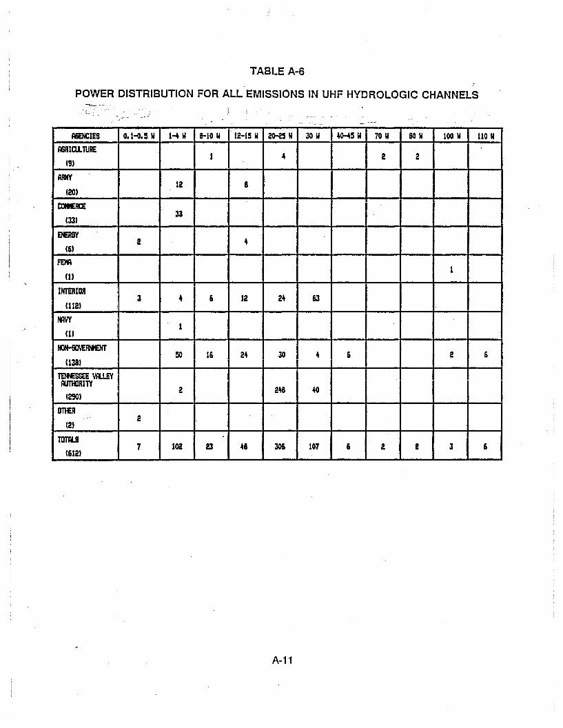
TABLE A-6
POWER DISTRIBUTION FOR ALL EMISSIONS IN UHF HYDROLOGIC· CHANNELS
~. . ,_. -AGENCIES 0.1~.~ I' HI' 8-10 W 12-1S W 20-2:5 I' JOW ~~W 70 W 801' 100 W 110 I'
ASRIaLT1JRE4 2 21
(91
ARMY12 8
(201
COIERCE33
(331
EhERSY42
(61
FEMA1
UI
INTERIOR12 24 63:3 4 6
11121
IflYY1
UI
1«JrHiOVERtt£HTJO 4 6 2 6!lO 1& 24
11381
TElfESSE YlI.lEYMKlRITY
2 248 40(2901
Dn£R... 2
(21
TOTA.S102 48 306 107 & 2 a 3 67 23
(6121
A-11


APPENDIX 8
HYDROLOGIC ASSIGNMENTS IN NONHYDROLOGIC CHANNELS
Further investigation of the GMF revealed that hydrologic operations are being conductedin the nonhydrologic channels by both government and nongovernment agencies. Most of theagencies with hydrologic operations in hydrologic channels also have hydrologic operations inthe nonhydrologic channels. There are also agencies using nonhydrologic channels forhydrological operations without any assignments in the hydrologic channels.
A total of 28 VHF and 11 UHF nonhydrologic channels were identified as being usedby government and nongovernment agencies for hydrologic operations. The number andfrequencies of the channels used by each agency are presented in TABLES B-1 (VHF) and B2 (UHF). Some of these channels are used by more than one agency for hydrologic operations.
A total of 384 (VHF) and 15 (UHF) assignments representing hydrologic operations wereidentified for these nonhydrologic channels. The distribution by agency of the assignments,station classes, emission types, and power specifications is shown in TABLES B-3 (VHF) andB-4 (UHF). The assignments exhibit single, dual, or multiple station occurrences, as happenedwith the hydrologic channel assignments.
The distribution of the station classes and emission characteristics also follow the samepattern exhibited by the hydrologic channel assignments. The majority of the stationscorrespond to the Fixed Service, with 96% (VHF) and 93% (UHF) of the assignments, and therest correspond to the Mobile and Land Mobile Services. The predominant emission types areagain 16KF2D (FM digital-data subcarrier) and 16KF3E (FM analog single-channel voice), whichrepresent 91 % (VHF) and 55% (UHF) of all emissions. The bandwidth specification again neverexceeds 20 kHz, and the diversity in the power specification is again evident.
B-1

TABLE B-1
NONHYDROLOGIC CHANNELS USED FOR HYDROLOGIC OPERATIONSIN THE VHF BAND
iII·
FREQUENCIES (MH:) I
164 1500 166 6750 I
CHANNELSUSEDAGENCIES
AGRICUL.TURE • , •169.27:50, 169.37:50170.37:50
AIR FORCE 1 173.437:5
ARMY 6 163.412:5, 163.037:5163.162:5, 169.:57:50170.37:50, 171.97:50
COMMERCE I :s I 162.1:500, 163.3000 I
166.07:50, 169.02:50170.1000
ENERGY 1 163.7937
FAA 1 I 16:5.737:5
INTERtoR I10 163.02:50, 164.42:50
II 164.47:50, 166.2000166.8000, 166.92:50169.:57:50, 170.0000170.37:50, 171.97:50
INTERNATIONAL. BORDER 2 172.47:50, 173.17:50AND WATER COMMISSION
NON-GOVERNMENT 2 169.:57:50, 170.37:50
TENNESSEE VALLEY 3 162.02:50, 172.02:50AUTHORITY
B-2

TABLE B-2
NONHYDROLOGIC CHANNELS USED FOR HYDROLOGIC OPERATIONSIN THE UHF BAND
I I II CHANNELS
IAGENCIES USED FREQUENCIES (MHz)
ARMY 2 I 406.2~00, 407.~~00
I
I406.4906, 409.S6~6ENERGY 2
INTERIOR 3 406.2~00, 411.62:50411.6~00
INTERNATIONAL BORDER 1 412.12~0
AND WATER COMMISSION
I,
NON-GOVERNMENT ei 406.2:00, 406.37~0
405.92:50, 405.9~00
410.0750
B-3

TABLE B-3
HYDROLOGIC ASSIGNMENTS IN NONHYDROlOGIC VHF CHANNELS
IAGaCIES NO. tF HYDRO STATIaf CUSS ~IDTH AND Pa€R
ASSIGlfENTS ea:tJRIlENl:S (TOTrL) I«JtU.SlTION TYPE occ:tlRRaaSIN IOHffDRO OCOJRREJaS (TOTrL) (TOTrL)FRmJElCIES
';;RIctl.TUllE 41 FtH/Fl. (2) FtHR/F'LR (2) l6i<F2D (76) 16KF3D (2) 2M (4) 51 (411FX (1) FXH (2) l6i<F3£ (77) 8W (1) lOW (S)FXH/FX (62) FXHR/FXR (2) 20W (2) 25f (93)IOf/MO (6) JlDlR/MOR (2) 60W (8)
AIR FOIa 2 FXH (2) 6i<F2D (2) lOW (2)
ARMY 0\3 Fnt (11) FXHlFX (2S) 15<F2D (29) 161<F'..D (16) 2M (2) 3W (1)FXHRlFXR (4) lW2E (1) 16KFJE (29) oW (25) 51 (S)
16i<F3F (1) 8W (10) lOW (2)18W (6) lSi (4)~ (2) 2QW (4)70W (4) 60W (6)
eatEliCE 1~ I FXH (141) FXHR (S) 11cmD (12) 16KFJD <1;39) Iat (4) 8W (132)f(H/FX (3) FXH/FXH (7) 16l<F"~ (16) lOW (14) 1~ (3)F£HR/FXHR (1) 20W (4) 2S' (9)
4QW (2)
ENERGY 1 FUt (1) I9I<F3llfM (1) 2M (1)
FAA 2 F1H (2) l6i<F2D (2) 5' (2)
INTERIOR 117 F3R (1) FXER (1) 1&KF2D (119) 16KFJE (112) 4W (96) 8W (4a)FXH (6) FXH/FX (107) lOW (2) 1~ (6)FnlR/FXR (3) II. (U 251 (40) 30W (2)
4QW (28):lOW (2) .&OW (3) l10W (9)
IHTERNATIlJA. BORDER 6 FXH/FX (3) FXHR (1) 16i<F2D (6) 16KF"'JE: (8) 151 (6) 60W (4)AND WATER CIJIlISSla. FXHRlFXR (2) MO (2) l00w (4)
~ 14 FXH (8) FXH/FX (6) l6i<F2D m 2OKF2D (11) 30W (6) WI (12)2OI<F3C: (8) 120W (2)
Tef£S& VlU£Y 3 FXHR (1) FXH/FX (2) 16l<F2D (3) 16KFJE (3) at (1) 60W (4)MltJRITY
8-4

TABLE B-4
HYDROLOGIC ASSIGNMENTS IN NONHYDROLOGIC UHF CHANNELS
A6EICIES If3. a:: HYDRO STATIa.a..qss I BANDWIDTH IlHD PG€/lASlllliNENTS CCClJRRam (TOTlI.) ~TIa. TYPE CCClJRRemIN IO+-HYDRO IXQJRRaCES 'TOTlI.) (TOTtL.)FREllElCIES
ARliIY 2 FXH m IOf m :ll<SlD l1l 1S<F2D (1) 211 (2)
ElERSY I 2 FXH (2) I 5<F2ll (2) 0.411 (2)
INTERIOR S FIN (1l FXHIFX (4) . 1Sl<F2D (:5) 161<F:lE (4) 51 (4) 1:14 (4)FXHRIFXR (1l 1001,I (1l
IH'T'ERNATICNl. SJRDER 1 FXHRIFlR l1l 16I<F2D (1) 161<F:lE (1) 2a' (2)AND WATER CtltlISSla.
IOHOYEI9EHT S FXH (S) 12l<F2Il (S) 1\1 (S)
8-5


APPENDIX C
WIRELESS MICROPHONE ASSIGNMENTS INWIRELESS MICROPHONE CHANNELS
Wireless microphone operations have been authorized on an unprotected basis to certainfrequencies located within the VHF hydrologic channel blocks, provided they do not interfere withother authorized government and nongovernment operations in the band. The wirelessmicrophone operations are restricted to eight specific frequencies, with 54 kHz maximumemission bandwidth and 50 milliwatts maximum output power, and their emissions are limitedto within ±32.5 kHz of their assigned frequency.
The GMF database (April 1989) was accessed to retrieve records on the wirelessmicrophone operations in the 162-174 MHz band. A total of 3,721 government andnongovernment assignments were found in the eight frequencies, and 3,653 (98%) of them areallocated to the nongovernment sector. The other 68 (2%) government assignments aredistributed among 13 government agencies.
The wireless microphone records were analyzed to identify the various station classes,modulation types, emission bandwidths, and power specifications, and the distribution by agencyand frequency are shown in TABLES C-1 to C-3. All stations correspond to the Land MobileService, with 99% of them representing land mobile (LM) stations, and the rest being land mobileportable (MLP) or base (FB) stations.
The modulation type and emission bandwidth employed varies with different agencies,but remains very consistent throughout the eight channels for a given agency. The predominantemission designators are 8KA3E (8 kHz DSB/AM analog voice), 20KF3E (20 kHz FM analogvoice), and 54KF3E (54 kHz FM analog voice). The power specification is 50 milliwatts in 94%of the wireless microphone operations.
C-1

TABLE C-1
STATION CLASS DISTRIBUTION FOR ALL WIRELESS MICROPHONECHANNEL ASSIGNMENTS
------
FREQUENCIES OllzlA6ENCIES
169.5050 170.2450 170.3050 171.0450 171.1050 171.M50 171.9050(To'.1 Allignllntl) 169.4450
AIR FORCE IL (3) IL (2) ILlU II.lU ILlU IL (2) II.lU IL (31(14)
ARMY UlU U (3) UlU Il.P (21 U (2) Il.P (3) UlU UlU(141
I ADMINISTRATIVE CfFICEI I
IF Tl£ U. S. COURTS ILUl II.lU(2)
COMtERCE ILUl ILW(21
FUlUEt£R6Y II. (21 II.lU II. (2)
(6) UlU
FEDEIW. aERGErCfMANAGEMENT AGElCY ILlU ILlU ILlU ILlU ILlU II.lU
(6)
I£Al.TH ANDIUlAN SERVICES UlU UlU
(2)
I NATIONAL AERfHmICS I I K.P lU I I I I I IiLP m IAND SPACE ADMINI8TRATI~ UlU
(3)
NAVY II.lU ILUl IL (2) II.lU(In
,
tGHOYERtIEHT IL (20:5> IL U061 IL (319) IL (2971 K. U081 K. U3041 IL (14) K. (198)(3,6S31 XD (~) XD (~)
STATE II.Ul II.Ul II.lU II.Ul(4)
U. S. POSTII. SERVICE ILlU ILlU(2)
VETERANS ADMINISTRATl~ II.Ul II. (2) 11.(1) II. (3)m •
OTI£R IiLPUlUl
C-2

TABLE C-2
POWER DISTRIBUTION FOR ALL WIRELESS MICROPHONECHANNEL ASSIGNMENTS
.- ,,=,"-"".-_.~;... - -" "-:~_ •. ' '-'~'--' - -'-.::,...-".
' .. i FREGlEM::IES (Kiz)AGENCIES
Clot.l AlligJ1llnb) 169.44~ 169.~~ 170.2~~ 170.30~ 171.04~ 171.1050 171.8450 171.9050
AIR FORCE ~ (3) 50IIW (2) ~(1) 50IIW m 50IIW (1) 50IIW (2) so.w (1) 50IIW (3)(W
ARMY 50IIW (1) 5OIW(3) 50IIW (1) 50IIW (2) 50IIW (2) 50IIW (3) 50IIW (1) 50IIW (1)(W
ADMINISTRATIVE a:FlCEI
tF T~ U. Sa COORTS ~(1) ~lU(2)
ClJIERCE 1~ (1) 15l1W (1)(2)
HR6Y SOIW (2) 50IIW (3) 50IIW (2)(6)
FEDEIW. B£RGENCYHAHA6EMEH1' AGENCY l50IIlI (1) SOlIN lU SOlIN lU SOIW (1) 50IIW lU SOIW (1)
(6)
I£ALTH ANDII.It¥W SERVICES SOIW (1) SOIIIf (1)
(2)
NATI[JR. AERttWJTICS Il50IIlI (1) I IAND SPACE ADMINISTRATllIf eo.w (1) 50IIW U)
(3)
NAVY 50IIW (1) SOlIN (1) SOIIIf (2) 50IW m(S)
toHOVERNMENT 3IW(1) 20IlIW (1) 20tIW (1) 2'-If (84) 20IW lU 2SIW (~) 20IW lU 3IWm(3,6S3) ~lU 251M (3) 2SIW (2) 30IW (1) es.w (3) 50IIW mo(» 2SIW (2) 15l1W (1)
2s.N (3) 50IIW (02) so.w (316) SOIIW (12) 50IIW (04) 50IIW (111) 20IlIW (1)SOlIN (20S) 2SIW (2)
50IIW (198)
STATE SOIW (1) 50IIW (l) SOIW (1) SOlIN (1)(4)
U. S. POSTA. SERVICE l50IIlI (1) SOIW (1)(2)
VETERANS AIlMINISTRATIIIf SOlIN (1) SOlIN (2) 50IW lU 50IIW (3)(7)
DTf£R{ l50IIlI (1)(1) '-. ~
C-3

TABLE C-3
EMISSION DESIGNATOR FOR ALL WIRELESS MICROPHONECHANNEL ASSIGNMENTS
--
FREQUENCIES Olfz)AGENCIES
(Total AliignHnb) 169.44llO 169. ~llO 170.24llO 170.30SO 171.04llO 171.1050 171.84llO 171.9050
AIR FORCE S4KF3E131 54KFJE121 54KF3E(I) 54KF3Elll 54KF3Elll 54KFJE(2) 54KF3Ell) 54KF3E131U41
ARMY 541<F3E<U 16KFJE(2) 541<F3E<U 54I<FJE121 54KF3E(2) 161lF3E121 54KF3Ell) 54KFJE<UU41 ~JEUl 54KFJEll)
ADMINISTRATIVE lFFICE 54I<FJElll 541<F3EUlIF TI£ U. S. COORTS
121
ctMERCE 12KF3ElU 121<FJElU(2)
eERSY 32KOS3E 11 I 32KF3E(2) 321<FJElU(6) 54KF3ElU 32K05F3EI1) 321<FJElU
FEDERAL El£RGaCY 8I<F3ElU 8I<F3E<U 8I<FJElU 8I<FJElU SKF3EUl 8I<FJEUlMANAGEMENT AGENCY
(6)
tm..TH AND 54I<FJEll) 54l<F3ElU~ SERVICES
(2)
NATIOHrtL. AER04AUTICS 30KFJEUl 3OKF3ElU 3OKF3EmAND SPACE ADMINISTRATIIJf
131
NAVY 3OKF3Em 3OKF3Em lSKFJEl1I 18KF3Em(3) 30KFJElU
t«lN-6OVERtfIEHT SI<A3E(4U Sl<A3El4U SKA3E14U 8!<A3E14U BKA3EHU Sl<A3El4U BKA3E(4U Sl<A3E(4U(3, WI 151<FJE(4) 151<FJE(3) 151<FJEm 151<FJEU9U 15KFJE(3) 15KFJE(3) 151<FJEUl 121<FJElU
2OKF3EU041 2OI<F3ElS) 16l<F3E(9) 161<F3E(2) 2OKF3E(S) 161lFJE(91 2OKF3ElS) 151<FJE(2)44I<FJE(5) 44KFJEll) 20KFJE(1202) 2OKF3E(9) 44KF3E141 2OKFJEUl97) 44KF3E(41 2OKFJEUOO)54I<FJE(56) 54I<FJE(53) 44KF3E161 44KF3ElU 54KF3EI521 44KF3Elll 54KF3EI601 44KFJElSI
54KF3E(60) 54KFJE(53) 54I<FJE (53) 54KFJEI5o\)
STATE 36KFJElU 36KF3ElU 36KFJElU 36KFJEm(41
U. S. POST'" SERVICE 3OKF3Em 30KFJEm(2)
,
VETERANS ADMINISTRATIIJf lSKA3Em I SKA3EUl ISl<A3EUl I 1SKA3E121 Im i 2OI<F3EUI i i2Ol<FJEm i
I I I I I II..O_TI£_ur ...,j ll6KF3EUl I__~ --_...._---
C·4

LIST OF REFERENCES
1. Bedrosian, E. and W. Sollfrey (1S8S), A Comparison of SSB-SC and Conventional AMunder a Peak Power Limitation, IEEE Trans. on Communications, Vol. 37, No.1, January.
2. Cohen, D., W. Grant and F. Steele (1989), Meteor Burst System CommunicationsCompatibility, NTIA Report 89-241, March.
3. Crandall, G. A. (1982), Spectrum Resource Assessment in the 406. 1-420 MHz Band, NTIAReport 82-91, January.
4. Flynn, F. P. and W. M. Moran (1984), Spectrum Resource Assessment in the 162-174MHz Band, NTIA Report 84-143, February.
5. IRAC Documents on Hydrologic Channels, Hydrologic Operations, Wireless MicrophoneChannels, and Wireless Microphone Operations: Document Nos. 23082/1, 23119/1,23135/2,23162/1,23229/1,24210/1,25048/1, 25121/1, 25123/1, 25159/1,25161/2,25796/1,25817/1,25819/1,25841/1,25843/1, 25874/1, 26223/1, 26315/1; 26321/1,26241/1.
6. IRAC Document 26332 (AGENDA) (1989), Allocation of the Subbands 932-932.5 MHzand 941-941.5 MHz to Government and Nongovernment Fixed Service for Single-Channel,Point-to-Multipoint Operations, February 28.
7. NTIA, Manual of Regulations and Procedures for Federal Radio Frequency Management,U.S. Department of Commerce, National Telecommunications and InformationAdministration, Washington, DC, January 1989 Revision.
8. Shelton, W., D. Cohen, G. Crandall, G. Hurt and W. Speights (1984), Assessment ofNarrowband Modulation Technologies for Government Land Mobile Operations, NTIAReport 84-156, August.
9. Sklar, B. (1983), A Structural Review of Digital Communications, IEEE CommunicationsMagazine, August.
10. Wacker, J. and S. Cohn (1986), Land Mobile Narrowband Technologies, EMC Technology,September-October.
R-1

~---- -- --- --- --- ---

FORM NTIA-29 U.S. DEPARTMENT OF COMMERCE1~~OI NAT"L. TELECOMMUNICATIONS AND INFORMATION ADMINISTRATION
BIBLIOGRAPHIC OATA SHEET
1. PUBLICATION NO. 2. Gov't Accession No. 3. Recipient's Accession No,
NTIA Report 90-259
4. TITLE AND SUBTITLE 5. Publication Date
HYDROLOGIC AND METEOROLOGICAL OPERATIONS IN THE MARCH 1990
162-174 AND 406.1-420 MHz BANDS 6. Performing Organization Code
7. AUTHOR(S) 9. ProjecVTaskiWork Unit No.
Cesar Filippi, Gary Patrick, Ernesto Cerezo, Robert WilS)I8. PERFORMING ORGANIZATION NAME AND ADDRESS 9010171National Telecommunications .and
Information Administration 10. ContracVGrant No.
179 Admiral Cochrane DriveAnnapolis, MD 21401
11. Sponsoring Organization Name and Address 12. Type of Report and Period Covered
U.S. Department of Commerce/NTIATECHNICAL179 Admiral Cochrane Drive
Annapolis, MD 21401 13.
14. SUPPLEMENTARY NOTES
15. ABSTRACT (A 200-word or less factual summary of most significant information. If document includes a significant bibliography or literaturesurvey, mention it here.)
This report presents a detailed assessment of the hydrologic and meteorological operations in the162-174 MHz (VHF) and 406.1-420 MHz (UHF) bands. These operations are currently supported byhydrologic and quasi-hydrologic channel assignments in these bands. There is a current need tojointly support hydrologic and nonhydroJogic operations representing important national programs,and to develop solutions that alleviate spectral congestion and promote efficient spectrum utilization.This report identifies current regulations and channel usage, and analyzes the hydrologic emissioncharacteristics to assess their bandwidth requirements and conservation alternatives. The currenthydrologic channeling plans are also analyzed, and narrowband channeling options are assessed,along with the potential hydrologic service reaccommodation in current or other bands. All potentialrelocation and channeling options are explained and compared to illustrate their impact, tradeoffs, andcompromises. The results of this stUdy can serve to improve the spectral efficiency of hydrologicoperations while remaining cost effective, and to conserve spectrum that can be made available for
, . ,"'''''...16. Key Words (Alphabetical order. separaled by semicolons)
162-174 MHz Band; 406.1-420 MHz Band; Hydrologic Operations;
Narrowband Channeling Plans; Spectrum Conservation;
Wireless Microphones<
17. AVAILABILITY STATEMENT 18. Security Class. (This report) 20. Number of pages
rnJ UNCLASSIFIED 112UNLIMITED.
19. Security Class. (This page) 21. Price:
0 FOR OFFICIAL DISTR'BUTION. .'UNCLASSIFIED
.U.S. Govemmenl Prtnling Ollice: 198()-6T8·~95'529