Embed Size (px)
DESCRIPTION
PPT of our project
Citation preview

Hydrogen Supplementation in CI engines
By:-
Harman Singh 09109044
Surendra Singh Dhaked 09109084
Surendra Kumar Meena 09109083
Avinash Kumar Roy 09109025
Project Guide :- Dr S.S Sandhu

Introduction To Use Hydrogen as part of air in A/F mixture with hydrogen
content varying from 10-30 % of energy value of diesel Development of Liquid seal flame arrestor To Study Effect of hydrogen supplementation in Engines
Performance and Emissions

Basic Concept and Why we use it
To Use Hydrogen for improving Combustion efficiency and hence increase overall efficiency and reduce emissions
Properties of Hydrogen makes it ideal for combustion engines
The only problem is at self igntition temperatures is very high that’s why directly in CI engines ,Even igntition is not achieved at CR’s of 29:1
The only option is to use it as supplement mode

Properties of hydrogen
High Calorific Value 141MJ/kg High Diffusity Wide Flammability (4-74 % in air) Low Ignition energy .02mJ High Flame speeds at stiochometric ratios(3.46 m/s)

Flow chart
Assembly of Experimental
Setup
Testing on Engine Test
Rig
Analysis of results

Experimental setup

Components
Hydrogen Cylinder at 200 bar Pressure regulator Flowmeter Flame arrestor Pressure Gauge Inlet manifold Single Cylinder engine Exhaust Hydraulic hoses

Flame Control systems
If there is any mixture imbalance flashback which can be catastrophic.Following systems will be used to control it Dry Flame arrestor Wet Flame arrestor

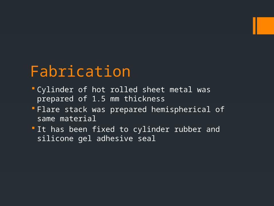
Liquid Seal Flame arrestor It is cylindrical vessel which will contain water and hydrogen is
passed through Maximum pressure in vessel can go up to 10 bar.Design method
of a pressure vessel was used In case of flashback water will cool down the flame and extinguish
it Instrumentation was done through pressure gauge and flow meter
at outlet
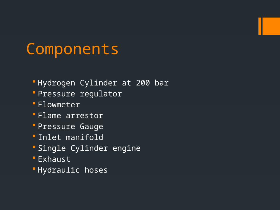
Fabrication Cylinder of hot rolled sheet metal was prepared of 1.5 mm
thickness Flare stack was prepared hemispherical of same material It has been fixed to cylinder rubber and silicone gel adhesive
seal

Analysis
Parameters to be analyzed
Engine Performance Parameters
1. Brake thermal efficiency

Calculation methods
Volume of hydrogen required :-
Brake thermal efficiency

Results and discussion Leakage test passed by using LPG System failed to check leakage of hydrogen at higher flow
rates Retrofitted system using epoxy seal

Results on diesel
Load(W) V I VI
output diesel power(W)
Input volume(cc) time taken fuel/s fuel/min
input power
Efficiency%)
200 188 0.5 94 130.5556 10 88.14 0.113456 6.807352 4065.577 3.211243
400 193 1.3 250.9 348.4722 10 72.13 0.138639 8.318314 4967.974 7.014372
600 197 2 394 547.2222 10 66.16 0.151149 9.068924 5416.264 10.10332
800 198 2.7 534.6 742.5 10 57.8 0.17301 10.38062 6199.654 11.97647
1000 197 3.5 689.5 957.6389 10 56.29 0.177651 10.65909 6365.962 15.04311

Calculation of required hydrogen
FUEL cc/min
fuel flow kg/hr
Energy Consumption (KJ/hr)
5% H2 Substitution (kg/ hr)
Absolute
Pressure of 5%
Hydrogen
(N/m2 or Pa)
Temperature of 5% Hydrogen (°K) H2 5%
(lpm)
H2 at 10% by mass
lpm at 10
H2 at 15% by mass
lpm at 15
H2 at 20% by mass
lpm at 20
H2 at 25% by mass lpm
H2 at 30% by mass lpm
6.8070.3389
8914237.
52120.005947168 200000 298
0.5754228
0.011894
1.150846
0.017842
1.726268
0.023789
2.301691
0.029736
2.877114
0.035683
3.452537
8.3180.4142
3617397.
92880.007267305 200000 298
0.703153643
0.014535
1.406307
0.021802
2.109461
0.029069
2.812615
0.036337
3.515768
0.043604
4.218922
9.0680.4515
8618966.
62880.007922568 200000 298
0.766554128
0.015845
1.533108
0.023768
2.299662
0.03169
3.066217
0.039613
3.832771
0.047535
4.599325
10.380.5169
2421710.
8080.009068842 200000 298
0.877462709
0.018138
1.754925
0.027207
2.632388
0.036275
3.509851
0.045344
4.387314
0.054413
5.264776
10.650.5303
722275.
540.009304737 200000 298
0.900286884
0.018609
1.800574
0.027914
2.700861
0.037219
3.601148
0.046524
4.501434
0.055828
5.401721

Final results
hydrogen energy input at 10 %
Diesel input during H2 supplementation(cc/s)
diesel energy input output(V) I Power efficiency
hydrogen energy input at 20 % diesel input(cc/s) power efficiency
406.5577 0.038462 1680.769 190 0.5 131.9444 7.817683 813.1155 0.037037 1618.519 131.944 5.426146
496.7974 993.5949
541.6264 1083.253
619.9654 1239.931
636.5962 1273.192

0.5 1 1.5 2 2.5 3 3.5 4 4.5 5 5.50
2
4
6
8
10
12
14
16 efficiency at 0% efficiency at 10 % efficiency at 20%

Discussion and epilogue
Efficiency is optimum around 10 percent of hydrogen at lower loads
At higher loads it is expected to have better improvement of efficiency
Can be calculated by improvement of flame trap

References ON-BOARD HYDROGEN STORAGE SYSTEMS FOR AUTOMOTIVE
APPLICATION BY L. M. DAS HYDROGEN COMBUSTION IN A COMPRESSION IGNITION DIESEL ENGINE BY
STANISLAW SZWAJA*, KAROL GRAB-ROGALINSKI PERFORMANCE AND EMISSION STUDIES ON PORT INJECTION OF HYDROGEN
WITH VARIED FLOW RATES WITH DIESEL AS AN IGNITION SOURCE BY N. SARAVANAN A,G. NAGARAJAN
COMBUSTION CHARACTERISTICS OF A DIESEL-HYDROGEN DUALENGINE BY W.B. SANTOSO1,2, A. NUR, S. ARIYONO1.A. BAKAR1
EXPERIMENTAL INVESTIGATION OF HYDROGEN ENRICHMENT ON PERFORMANCE AND EMISSION BEHAVIOUR OF COMPRESSION IGNITION ENGINE BY PULLAGUR, KAKELLI RAVI KUMAR, PIYUSH CHANDRA VERMA , ABHASH JAISWAL, R.PRAKASH, S.MURUGAN