Embed Size (px)
Citation preview

Hydrogen Production from the AirGang Kevin Li ( [email protected] )
The University of Melbourne https://orcid.org/0000-0003-1700-297XJining Guo
The University of MelbourneYuecheng Zhang
The University of MelbourneAli Zavabeti
University of Melbourne https://orcid.org/0000-0002-5860-8938Kaifei Chen
The University of MelbourneYalou Guo
The University of MelbourneGuoping Hu
University of Western Australia https://orcid.org/0000-0002-7480-8411Xiaolei Fan
The University of Manchester
Physical Sciences - Article
Keywords: Renewables Distribution, Freshwater Availability, Green Hydrogen Production, HygroscopicElectrolyte, Direct Air Electrolysis
Posted Date: July 15th, 2021
DOI: https://doi.org/10.21203/rs.3.rs-691931/v1
License: This work is licensed under a Creative Commons Attribution 4.0 International License. Read Full License

Hydrogen Production from the Air
Jining Guo1, Yuecheng Zhang1, Ali Zavabeti1, Kaifei Chen1, Yalou Guo1, Guoping Hu1, Xiaolei Fan2 and Gang
Kevin Li1✉
1.Department of Chemical Engineering, the University of Melbourne, Parkville, Victoria 3010, Australia.
2.Department of Chemical Engineering and Analytical Science, School of Engineering, The University of Manchester, Manchester,
M13 9PL, United Kingdom
✉email: [email protected]
Abstract
Hydrogen gas (H2) produced by water splitting using renewable energy, namely green hydrogen, is the most
promising energy carrier of the low-carbon economy1-6. However, the geographic mismatch between
renewables distribution and freshwater availability poses a significant challenge to green hydrogen
production7-9. Here, we demonstrate a method of directly producing H2 from the air, namely, capturing
freshwater from the atmosphere using hygroscopic electrolyte and converting it to H2 by electrolysis powered
by solar energy. A prototype H2 generator has been successfully established and operated for 12 consecutive
days with a stable performance at an average Faradaic efficiency around 95%. This so-called direct air
electrolysis (DAE) module can work under low relative humidity (20%) environment, overcoming water
supply issues and producing green hydrogen sustainably with minimal impact to the environment. The DAE
modules can be easily scaled to provide H2 to remote, arid/semi-arid, and scattered areas.
Main
Hydrogen is the ultimate clean energy. Despite being the most abundant element in the universe, hydrogen
exists on the earth mainly in compounds like water. H2 produced by water electrolysis using renewable energy,
namely, the green hydrogen, represents the most promising energy carrier of the low-carbon economy1-3. H2
can also be used as a medium of energy storage for intermittent energies such as solar, wind, and tidal4-6.
The deployment of water electrolyzer is geographically constrained by the availability of freshwater, which,
however, can be a scarce commodity. More than one-third of the earth's land surface is arid or semi-arid,
supporting 20% of the world's population, where freshwater is extremely difficult to access for daily life, let
alone electrolysis7,8. In the meanwhile, water scarcity has been exacerbated by pollution, industrial
consumption, and global warming. Desalination may be used to facilitate water electrolysis in coastal areas,
however, substantially increasing the cost and complexity of hydrogen production. On the other hand, areas
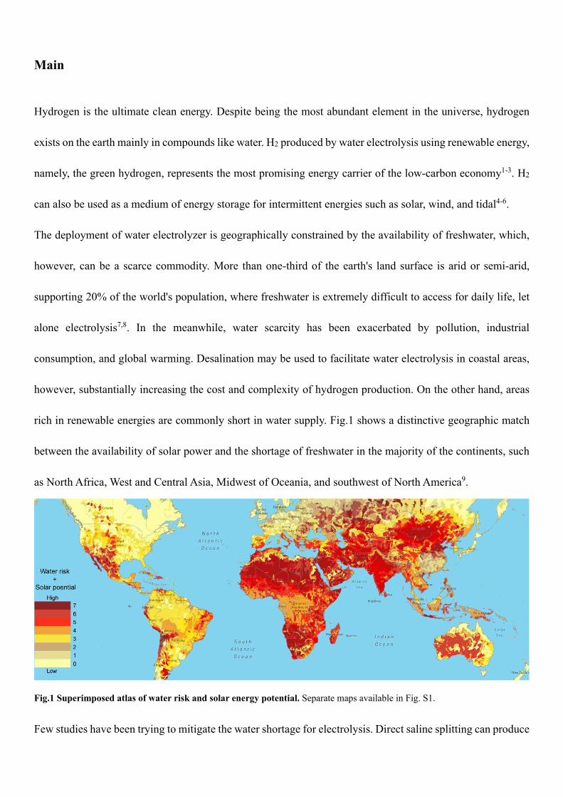
rich in renewable energies are commonly short in water supply. Fig.1 shows a distinctive geographic match
between the availability of solar power and the shortage of freshwater in the majority of the continents, such
as North Africa, West and Central Asia, Midwest of Oceania, and southwest of North America9.
Fig.1 Superimposed atlas of water risk and solar energy potential. Separate maps available in Fig. S1.
Few studies have been trying to mitigate the water shortage for electrolysis. Direct saline splitting can produce
hydrogen, which, however, faces a serious challenge of handling chlorine byproduct10,11. Some proton/anion
exchange membrane electrolyzers can use vapor carried by inert gases as a feed; however, the electrolyzers
must operate in an air-free atmosphere12-16.
In this work, we corroborate that moisture in the air can directly be used for hydrogen production via
electrolysis, owing to its universal availability and natural inexhaustibility17-21 – there are 13 trillion tons of
water in air which is in a dynamic equilibrium with the aqua-sphere. For example, even in the Sahel desert,
the average relative humidity (R.H.) is about 20 %22, and the average daytime R.H. at Uluru (Ayers Rock) in
the central desert of Australia is 21%23. Considering deliquescent materials such as potassium hydroxide,
sulfuric acid, propylene glycol24,25 can absorb water vapor from the air at an R.H. below 20%, here, we
demonstrate a method to produce hydrogen by electrolyzing hygroscopic solutions exposed to air. The
electrolyzer operates steadily under a wide range of R.H., as low as 20%, while producing high purity
hydrogen with a Faradaic efficiency over 95% for more than 12 consecutive days, without any input of liquid
water. A solar-driven prototype with five parallel electrolyzers has been devised to work in the open air,
achieving an average hydrogen generation rate of 745 L H2/day/m2 cathode, opening up a sustainable pathway
to produce green hydrogen without consuming liquid water.

Results
Design of the Direct Air Electrolysis (DAE) module for hydrogen production
Hydrogen production from the air was realized through our DAE module. As shown in the sandwich structure
in Fig. 2, this module consists of a water harvesting unit in the middle and electrodes on both sides paired with
gas collectors, powered by an external supply, for example, a solar panel. Importantly, the water harvesting
unit also serves as the reservoir to hold the electrolyte. Porous medium such as sintered glass foam is soaked
with deliquescent ionic substance to absorb moisture from the air via the exposed surfaces. The captured water
in liquid phase is transferred to the surfaces of the electrodes via diffusion and subsequently split into hydrogen
and oxygen in situ. Quartz wool is tightly packed in between the glass foam and the electrodes to ensure the
connectivity of the aqueous phase (Fig. S2-S4). The glass foam filled with ionic solutions forms a physical
barrier that effectively isolates hydrogen and oxygen from mixing.
Fig.2 The concept of direct air electrolysis (DAE) for hydrogen production. a) A schematic diagram of the DAE module with a
water harvesting unit made of porous medium soaked with hygroscopic ionic solution. b) Equilibrium water uptakes of hygroscopic
solutions at different R.H.24,25.
Deliquescent substances characterized with a strong affinity with water tend to extract moisture from the

atmosphere at exposure, absorbing sufficient water to form an aqueous solution which is hygroscopic in nature.
When the chemical potential (μ) of water vapor in the atmosphere is greater than that in a hygroscopic solution,
i.e. μair > μsolution, the solution will continue absorbing water vapor and being diluted until the vapor-liquid
equilibrium is reached at μair = μsolution26, making the concentration of the solution C equal to the equilibrium
one C*. In this study, we tested several deliquescent materials, including KOH, CH3COOK, and H2SO4,
representing a base, a salt, and an acid, respectively. All three materials spontaneously absorb moisture and
form ionic electrolytes. It was found that the direct air electrolysis modules using the respective electrolytes
were able to produce hydrogen gases successfully for an extended period with a continual supply of air and
power. However, the hydrogen evolution performance of the DAE module with KOH started to decline after
72 hr and stopped at 96 hr It was observed that the voltage of the DAE module increased from 2.30 V to 2.40
V due to the gradual conversion of KOH into K2CO3 and eventually KHCO3 at exposure to CO2 in the air.
KHCO3 is less soluble in water hence less conductive as an electrolyte, and critically it is non-deliquescent.
For CH3COOK based DAE module, the voltage was as high as 3.70 V due to the large size of acetate anions
and substantial ethane byproduct found along with O2 at the anode (Fig. S5).
Sulfuric acid was identified as one of the best hygroscopic materials that can absorb water from the air down
to concentrations of 10 wt% or below27. Meanwhile, the sulfuric acid solutions are high in conductivity (0.61
S cm-1 at 50.0 wt%)28,29, non-volatile, and it is non-toxic to the environment. In this regard, the following
studies were carried out with sulfuric acid electrolyte equipped with platinum (Pt) mesh electrodes (Fig. S6).
It is also interesting to note that in the concentration range of sulfuric acid of this work, the corresponding
freezing point is below -30 °C30, implying potential working temperature under icing environment.

Performance of the DAE module
The DAE module's performance was investigated using current density (J) and voltage (V) characteristic
experiments conducted at 25 °C. The effect of relative humidity ranging from 20% to 80%, as well as the pore
size and thickness of the sintered glass foams, were studied. Sintered glass foams were labelled as G1, G2 and
G3 corresponding to the pore size of 50−70, 30−50, 16−30 µm, respectively. Also, a series of experiments
with extended time durations of 288 hr was conducted to investigate the stability of the DAE module.
The effect of the different pore size of sintered glass foams on the J-V behavior is shown in Fig. 3a, using 62.0
wt% H2SO4 solution as electrolytes. Current density is negligible (<1 mA cm-2) at a voltage below 2.0 V due
to the overpotential of the Pt mesh. As long as the capillary force still holds the electrolyte, the current density
increases with the use of larger pored sintered glass foams, indicating higher conductivity and energy
efficiency for overall water splitting due to better mobility of electrolyte in larger pores. At 3.0 V, a current
density of 27.1 mA cm-2 was achieved using G3 sintered glass foam and it increased to 36.5 mA cm-2 using
G1 sintered glass foam. Therefore, the G1 sintered glass foam was chosen for further study of the foam
thickness, owning to the high electrical conductivity, low resistance, and high energy efficiency it brings to
the DAE module.
The sintered glass foam's thickness also plays a role in the J-V behavior. As shown in Fig. 3b, the J-V curve
shifts upwards with decreasing glass foam thickness. At 3.0 V, the current densities are 17.5 and 36.5 mA cm-
2 while using 2.5 and 1.5 cm thickness G1 sintered glass foams, respectively. According to Pouillet's law31,
the resistance is proportional to the distance between the electrodes, suggesting that a large distance between
the cathode and anode contributed to high resistance for overall water splitting. Hence, under specific current
density, the gap between two electrodes should be as small as possible to maintain relatively high energy
efficiency. However, the mass transfer area for water absorption is proportional to the sintered glass foam's
thickness. There is a trade-off between the water absorption area and conductivity. Considering both factors,

we chose the G1 sintered glass foam with 1.5 cm total thickness for further investigation, given that it could
provide sufficient mass transfer area for air-electrolyte contact while maintaining moderate energy efficiency.
The observed experimental concentration of sulfuric acid C is constantly above its equilibrium concentration
C* during the direct air electrolysis process. This difference represents the driving force for the mass transfer
of water from the vapor phase into electrolyte solution and then onto the electrochemical reaction sites at the
electrodes. Fig. 3c shows that at J=15.0 mA cm-2, the experimental concentration in the DAE module is
approximately 5wt% higher than the equilibrium at steady state, which means a stable in-situ H2SO4
concentration over 8 hours under a constant current density, where the rate of water absorption from air equals
the rate of water consumption by electrolysis. Likewise, such steady-state mass transfer driving force can be
established at fixed air relative humidity. As shown in Fig.3c inset, the driving force increases proportionally
with the increase of current density, which means the rate of water absorbed by the DAE module rises when
the water electrolysis rate is turned up. For instance, at R.H. = 80%, if a minimal current density is applied,
the sulfuric acid concentration in the module is close to the equilibrium 𝐶𝐶𝐻𝐻2𝑆𝑆𝑆𝑆4∗ = 26.8 wt%, and the mass
transfer driving force of water absorption is nearly zero. If we increase the current density J to 70 mA cm-2,
the steady-state concentration of sulfuric acid is increased to 46.7 wt%, 75 % higher than the equilibrium one 𝐶𝐶𝐻𝐻2𝑆𝑆𝑆𝑆4∗ = 26.8 wt%. Therefore, our DAE module is intrinsically self-converged, compatible with a broad range
of air humidity and current density.
The DAE module's J-V behavior has also been studied under different H2SO4 concentrations (Fig. 3d). With
the decrease of H2SO4 concentration from 62.5 wt% to 32.6 wt%, the current density for the electrolysis
reaction increases significantly from 37.5 mA cm-2 to 97.0 mA cm-2, under a constant voltage of 3.0 V. Such
change can be attributed to the improved electrical conductivity of diluted H2SO4 (Fig. S7)28,29. Also, the
viscosity of the electrolyte decreases as the acid is being diluted (Fig. S8), resulting in higher electrocatalytic
activity and reduced electrochemical polarization32,33.

Fig.3 DAE module performance at 25 °C.
a) J–V curves for modules using various porous substrate with different pore sizes. b) Effect of foam thickness on J-V performance.
c) The experimental steady state concentration of sulfuric acid at J =15.0 mA cm-2 (red) VS equilibrium concentration 𝐶𝐶𝐻𝐻2𝑆𝑆𝑆𝑆4∗
(black) under different R.H.. The inset shows the effect of current density on steady state concentration under 80% R.H. where
𝐶𝐶𝐻𝐻2𝑆𝑆𝑆𝑆4∗ = 26.8 wt% (red dashed line). d) The effect of electrolyte concentration on J–V performance. e) Example recording of cell
voltage (black symbol), H2SO4 concentration (red symbol) and 𝐶𝐶𝐻𝐻2𝑆𝑆𝑆𝑆4∗ = 47.7 wt% (red dashed line) for DAE modules at constant

current density of 15.0 mA cm-2 for 288 hr at 40 % R.H.. f) Current density collected under different voltage for 288 hr at 40 %
R.H.. Fig. 3c to 3f were operated with G1 sintered glass foam and 1.5 cm gap between the two electrodes.
The DAE module was found stable during continual electrolysis. Performance of the electrolysis cell at various
voltage, energy efficiency, and air R.H. are shown in Table S1 and Fig. S9. After a minor fluctuation initially,
the J-V behavior stabilize for a 48 hr run. For further laboratory test, we chose 40% R.H. air as the gas
atmosphere condition. As shown in Fig. 3e, the concentration of H2SO4 fed to the module was 55.0 wt%
initially, and it converged to 51.1 wt% over the first 120 hr In the following 168 hr, the electrolyte
concentration, the DAE module's voltage, and the mass transfer driving force for moisture absorption (ΔC =
Cexp[51.1 wt%] - C*[47.7 wt%] = 3.4 wt%) all stabilized. Accordingly, the corresponding current densities
collected under specific voltages (2.4, 2.7, 3.0 V) also reached steady state in this 12 day continual operation
(Fig. 3f). This result indicates excellent adaptability and long-term stability of the DAE modules under
different air R.H., cell voltage, and electrolyte concentrations.
Demonstration of DAE modules stack with solar panel in the open air
To further demonstrate the DAE module's working capability in a practical environment, we designed and
constructed a free-standing hydrogen generation tower consisting of five DAE modules stacked in parallel
superimposed vertically with a solar panel for power supply. The details of the structure of the tower are shown
in Fig. 4a and Fig. S10. One of the advantages of such design is that the footprint of the tower is no more than
the solar panel, meaning our DAE will not occupy extra land, which can be costly in some areas. The tower
was tested for two days, 8 hr per day, in the open air of a hot-dry summer (Mediterranean climate) in the
campus of the University of Melbourne. The setup of the module of the outdoor surroundings is provided in
Video S1. The outdoor temperature varied from 20 °C to 40 °C, and the relative humidity ranged from 20%
to 40% over the testing period. Since the solar panel was used as a renewable energy supply, the voltage, and
the current of each DAE module were solely determined by solar intensity (Video S2), which varies every

hour. The product hydrogen gas evolved from the cathode was collected in an inverted, water-filled cylinder
over water, which was then used to examine the gas production rate (Video S3). The oxygen generated on the
anode of the DAE was vented into the air.
The performance of the tower was shown in Fig. 4b and Fig. S11, in the form of the hydrogen generation rate,
hydrogen evolution Faradaic efficiency (𝜂𝜂𝑓𝑓,𝐻𝐻2 ), the overall current and the voltage. During the open-air
demonstration, 𝜂𝜂𝑓𝑓,𝐻𝐻2 was over 90% during the daytime, shown as the red line in Fig. 4b. On the first day,
when the weather was sunny, the current output was stable around 400 mA and voltage 2.68 V. The hydrogen
evolution rate was 186 ml h-1, with the total hydrogen production at 1490 ml in a day, which is equivalent to
745 L H2/day/m2 of the cathode, or 3.7 m3 H2/day/m2 tower.
On the second day, a few hours of good sunlight guaranteed the current output stable at 400 mA from 9:00 to
13:00, with an average hydrogen generation rate of about 179 ml h-1, similar to that of the first day. However,
in the early morning from 8:00 to 9:00, the solar intensity was limited, resulting in a relatively lower current
output of 270 - 370 mA and a hydrogen generation rate of 140 ml h-1. In the cloudy late afternoon (14:00 to
16:00), the poor weather conditions reduced the solar panel's current output to as low as 50 mA, and hence,
the hydrogen generation rate dropped to 21 ml h-1. On the whole, under non-ideal weather conditions, the total
hydrogen production could still reach 1188 ml on the second day.
The gas product collected from the cathode has been analyzed with gas chromatography (GC.), suggesting
pure hydrogen. The gas produced from the anode has also been measured (Fig. S12) with a GC. showing it is
a high purity oxygen. The Faradaic efficiency of oxygen 𝜂𝜂𝑓𝑓,𝑆𝑆2at the anode is over 91.0%. Since the Faradaic
efficiency of both H2 and O2 measured and calculated by energy and mass balances are comparable, we can
confirm the overall electrolysis is a water-splitting process.

Fig.4 Open-air demonstration of the hydrogen generation tower in Dec 2020 Melbourne. a) Photo of the designed hydrogen
generation tower featuring scalable DAE modules with minimized footprint. b) Hydrogen generation rate and Faradaic efficiency
on an hourly basis at corresponding air humidity and temperature for two days under different weather conditions.
Discussion
In summary, to overcome the water shortage problem in the case of widespread deployment of hydrogen
production, we have demonstrated a method of producing high purity hydrogen from the air by using
hygroscopic electrolyte soaked in a porous medium as the moisture absorbent. Such direct air electrolysis
(DAE) module can operate under a broad range of air humidity, electrolyte concentration, and current density,
for more than 12 days continuously without any decay and without any attendance, performing at a hydrogen
Faradaic efficiency of around 95%. This DAE module can be easily scaled up and integrated with renewable
power. In our demonstration, a prototype of standalone hydrogen generation tower with five DAE modules
stacked in parallel superimposed vertically under a solar panel (with minimum footprint) was constructed and
tested outdoor in a hot-dry summer. The prototype achieved automated steady hydrogen production depending
on the solar intensity under varying weather conditions. On a warm sunny day, the hydrogen production rate

can reach 3.7 m3 H2/day/m2 tower. Such DAE farms, if further upscaled, can generate abundant hydrogen in
arid and semi-arid areas with negligible change to the regional air humidity and minimal impact to the
environment (Supplementary Note 1).

Method
DAE module fabrication
A self-designed DAE module was used under each R.H. in this project. More details can be found in the
Supplementary document. Pt mesh electrodes (99.99% purity, 20×20 mm + 0.5×20 mm, Yueci technology co.)
with geometric area 4 cm2 were attached directly to the quartz wool (99.95% purity, 5-10 µm, Xinhu co.), and
then connected with the sintered glass surfaces, with geometric area 7.84 cm2 (Shundao sintered glass foam
co.). The sintered glass foams' thickness was 3 mm, and quartz wool was layered between two foams. For
example, for 1.5cm total thickness, three foams and four layers of quartz wool were used stacked. Teflon plate
with Pt wireline (99.99% purity, Xudong Co. Ltd.) was used as current feeders and electrolyte distributors.
After assembly, the DAE module was put inside the climate test chamber (DHT-100-40-P-SD, Shanghai
Doaho Co. Ltd.), keeping a close environment at a constant R.H. and temperature. The DAE module connected
directly with a D.C. power supply (Wanptek DPS3010U), which could supply constant current for electrolysis.
The cathode's output gas production was bubbled through a water bath, and collected in an inverted, liquid-
filled cylinder.
Data collection
Another DC power supply (Nice Power R-SPS605D) was used to connect with the DAE module to collect the
current density vs. voltage (J–V) performance curve. The current was measured after 30 seconds under each
voltage, using an applied voltage from 1.80 V to 3.00 V with a 100-mV increase. The area of the electrode
was 4 cm2. Under each R.H., the J-V behavior was tested before putting into the environment oven and after
operating over 24 hours and 48 hours. Each J-V behavior was verified by repeated measurements three times,
with the current densities variation controlled within 5-10%.

Under each R.H., the DAE module was operated under constant current density, and the weight needed to be
checked each 4 hr until it maintained stable over an 8-hr period.
Faradaic efficiency
The gas product flowed into a measuring cylinder (25.0 mL) through a rubber pipeline for volume
measurement by a collection of gases in an inverted, water-filled cylinder over water. Gas collected inside the
cylinder was drawn out by the syringe and then pushed into the gas chromatography (GC.) system (7890B,
Agilent technologies) with a thermal conductivity detector (TCD.) for analyzation. The Faradaic efficiencies 𝜂𝜂𝑓𝑓,𝐻𝐻2 and 𝜂𝜂𝑓𝑓,𝑆𝑆2were compared to the gas production with the ideal production rate.
Stability test
55.0 wt% H2SO4 (formulated with 98% sulfuric acid and R.O. water) was used as the electrolyte and tested
under 40% R.H. and 25 °C in the climate test chamber for 12 days under constant current density 15.0 mA
cm-2.
Open air demonstration with solar panel
Five DAE modules was stacked vertically in parallel, and the hydrogen generation was collected. Supporters
were used to keep the distance between each unit. Here, a commercial silicon solar panel was connected in
series and put on the top of the units, with an open-circuit voltage of around 6.0 V and a short circuit current
around 400 mA under Melbourne's natural sunlight. The gas product was also flowed into a measuring
cylinder by collecting gases in an inverted, water-filled cylinder over water.
Data availability
The data that support the findings of this study are available from the corresponding author upon request.

Reference
1 Turner, J. A. Sustainable Hydrogen Production. Sci. 305, 972-974, (2004).
2 Abbasi, R. et al. A Roadmap to Low‐Cost Hydrogen with Hydroxide Exchange Membrane
Electrolyzers. Adv. Mater. 31, 1805876, (2019).
3 Gernaat, D. E. H. J. et al. Climate change impacts on renewable energy supply. Nat. Clim. Change,
(2021).
4 Lewis, N. S. Toward Cost-Effective Solar Energy Use. Sci. 315, 798-801, (2007).
5 Jia, J. et al. Solar water splitting by photovoltaic-electrolysis with a solar-to-hydrogen efficiency over
30%. Nat. Commun. 7, 13237, (2016).
6 Landman, A. et al. Photoelectrochemical water splitting in separate oxygen and hydrogen cells. Nat.
Mater. 16, 646-651, (2017).
7 Okin, G. S., Gillette, D. A. & Herrick, J. E. Multi-scale controls on and consequences of aeolian
processes in landscape change in arid and semi-arid environments. J. Arid Environ. 65, 253-275,
(2006).
8 Wickens, G. E. in Ecophysiology of Economic Plants in Arid and Semi-Arid Lands 5-15
(Springer Berlin Heidelberg, 1998).
9 Hu, G. et al. A Review of Technical Advances, Barriers, and Solutions in the Power to Hydrogen (P2H)
Roadmap. Engineering, (2020).
10 Tong, W. et al. Electrolysis of low-grade and saline surface water. Nat. Energy, (2020).
11 Dresp, S., Dionigi, F., Klingenhof, M. & Strasser, P. Direct Electrolytic Splitting of Seawater:
Opportunities and Challenges. ACS Energy Lett. 4, 933-942, (2019).
12 Kumari, S., Turner White, R., Kumar, B. & Spurgeon, J. M. Solar hydrogen production from seawater
vapor electrolysis. Energy Environ. Sci. 9, 1725-1733, (2016).

13 Kistler, T. A., Um, M. Y. & Agbo, P. Stable Photoelectrochemical Hydrogen Evolution for 1000 h at
14% Efficiency in a Monolithic Vapor-fed Device. J. Electrochem. Soc. 167, 066502, (2020).
14 Heremans, G., Bosserez, T., Martens, J. A. & Rongé, J. Stability of vapor phase water electrolysis cell
with anion exchange membrane. Catal. Today 334, 243-248, (2019).
15 Heremans, G. et al. Vapor-fed solar hydrogen production exceeding 15% efficiency using earth
abundant catalysts and anion exchange membrane. Sustain. Energy Fuels 1, 2061-2065, (2017).
16 Spurgeon, J. M. & Lewis, N. S. Proton exchange membrane electrolysis sustained by water vapor.
Energy Environ. Sci. 4, 2993, (2011).
17 Hanikel, N., Prévot, M. S. & Yaghi, O. M. MOF water harvesters. Nat. Nanotechnol. 15, 348-355,
(2020).
18 Kim, H. et al. Adsorption-based atmospheric water harvesting device for arid climates. Nat. Commun.
9, (2018).
19 Xu, W. & Yaghi, O. M. Metal–Organic Frameworks for Water Harvesting from Air, Anywhere,
Anytime. ACS Cent. Sci. 6, 1348-1354, (2020).
20 Kalmutzki, M. J., Diercks, C. S. & Yaghi, O. M. Metal-Organic Frameworks for Water Harvesting
from Air. Adv. Mater. 30, 1704304, (2018).
21 Fathieh, F. et al. Practical water production from desert air. Sci. Adv. 4, eaat3198, (2018).
22 Rongé, J. et al. Air-based photoelectrochemical cell capturing water molecules from ambient air for
hydrogen production. RSC Adv. 4, 29286, (2014).
23 Bureau of Meteorology. Climate statistics for Australian locations,
<http://www.bom.gov.au/climate/averages/tables/cw_015635_All.shtml> (2021).
24 Solomon, M. Control of humidity with potassium hydroxide, sulphuric acid, or other solutions. Bull.
Entomol. Res. 42, 543-554, (1951).

25 Steele, R. J. Use of polyols to measure equilibrium relative humidity. Int. J. Food Sci. 22, 377-384,
(1987).
26 Åberg, C., Sparr, E., Edler, K. J. & WennerströM, H. K. Nonequilibrium Phase Transformations at the
Air−Liquid Interface. Langmuir 25, 12177-12184, (2009).
27 Kiradjiev, K. B. et al. A Simple Model for the Hygroscopy of Sulfuric Acid. Ind. Eng. Chem. 59, 4802-
4808, (2020).
28 Darling, H. E. Conductivity of Sulfuric Acid Solutions. J. Chem. Eng. Data 9, 421-426, (1964).
29 Muller, T. L. Sulfuric Acid and Sulfur Trioxide. Kirk-Othmer Encyclopedia of Chemical Technology,
(2000).
30 Kölbach, M., Rehfeld, K. & May, M. M. Efficiency gains for thermally coupled solar hydrogen
production in extreme cold. Energy Environ. Sci., (2021).
31 Woan, G. The Cambridge handbook of physics formulas. (Cambridge University Press, 2000).
32 Rhodes, F. & Barbour, C. The viscosities of mixtures of sulfuric acid and water. Ind. Eng. Chem. 15,
850-852, (1923).
33 Lei, Q., Wang, B., Wang, P. & Liu, S. Hydrogen generation with acid/alkaline amphoteric water
electrolysis. J. Energy Chem. 38, 162-169, (2019).

Acknowledgements
J. G. is grateful for the Melbourne-Manchester Graduate Research scholarship.
Author information
Affiliations
Department of Chemical Engineering, the University of Melbourne, Parkville, Victoria 3010, Australia
Jining Guo, Yuecheng Zhang, Ali Zavabeti, Kaifei Chen, Yalou Guo, Guoping Hu, Gang Kevin Li
Department of Chemical Engineering and Analytical Science, School of Engineering, The University of
Manchester, Manchester, M13 9PL, United Kingdom
Xiaolei Fan
Contributions
G.L. conceived the idea. J.G. and Y.Z. conducted the experiments. J.G., G.L., A.Z. and Y.Z. analyzed the data.
K.C. and Y.G. helped with characterizations. J.G. led the draft of the manuscript with input from G.L., A.Z.,
X.F., G.H. and Y.Z..
Corresponding author
Correspondence to Dr. Gang Kevin Li
Telephone: +61 3 9035 7514
Email: [email protected]

Ethics declarations
Competing interests
The authors declare no competing interests.
Supplementary Information
Supplementary Information
This file contains additional data to support the conclusions of the manuscript including details of DAE
modules, prototype, and composition of gas production.
It contains Supplementary Fig. S1 to S12, Supplementary Table S1 to S2, Supplementary Note 1,
and Supplementary References.
Supplementary Video 1
Prototype of hydrogen generation tower
Supplementary Video 2
Effect of solar intensity
Supplementary Video 3
Real-time hydrogen generation

Supplementary Files
This is a list of supplementary �les associated with this preprint. Click to download.
Supplementaryvideoslinks.pdf
SupplementaryInformation.pdf