Embed Size (px)
Citation preview

Hydrogen production and storage: an overview
Dr. Antonella Glisenti - Dip. Scienze Chimiche - Università degli Studi di PadovaProf. Antonella Glisenti - Dip. Scienze Chimiche - Università degli Studi di Padova
Laurea in Scienza dei Materiali
Materiali Inorganici Funzionali

Bibliography
1. J.D. Holladay et al Catal. Today 139 (2009) 244
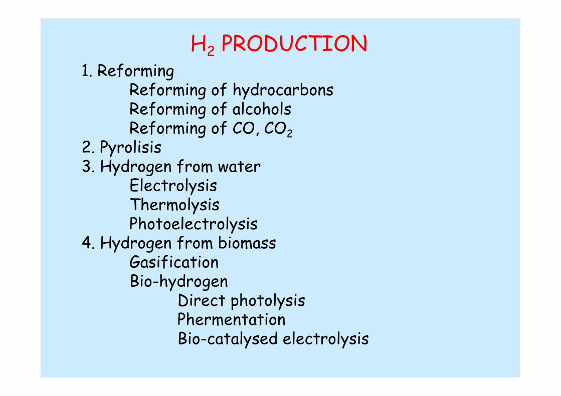
H2 PRODUCTION1. Reforming
Reforming of hydrocarbonsReforming of alcoholsReforming of CO, CO2
2. Pyrolisis3. Hydrogen from water
ElectrolysisThermolysisPhotoelectrolysis
4. Hydrogen from biomassGasificationBio-hydrogen
Direct photolysisPhermentationBio-catalysed electrolysis
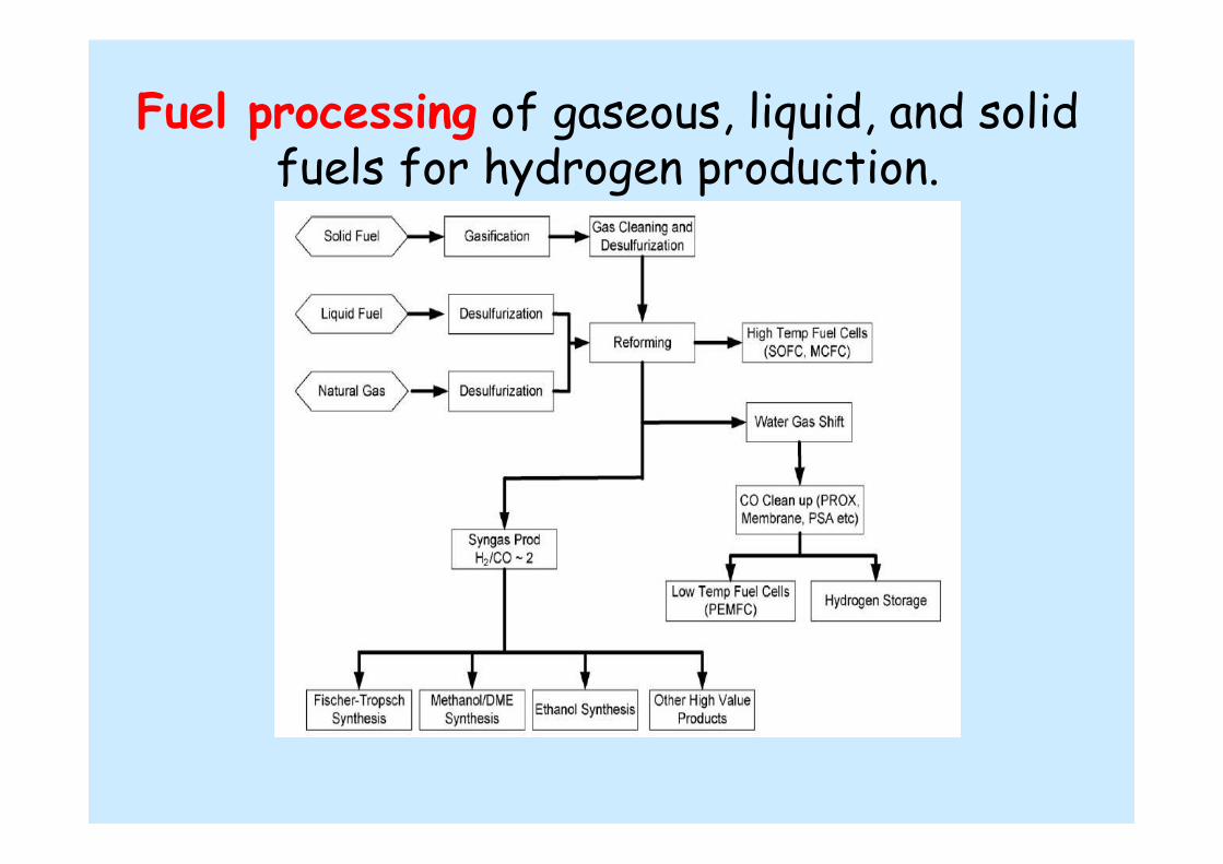
Fuel processing of gaseous, liquid, and solid fuels for hydrogen production.
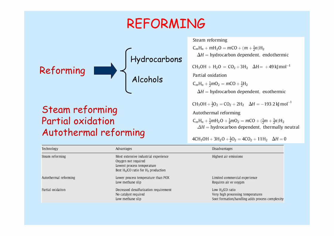
REFORMING
Steam reformingPartial oxidationAutothermal reforming
ReformingHydrocarbons
Alcohols

OTHER REACTIONS
Water Gas Shift (WGS) Oxidation
Coke FormationMinimum reaction temperatures
required for avoiding coke formation during isooctane reforming at thermodynamic equilibrium
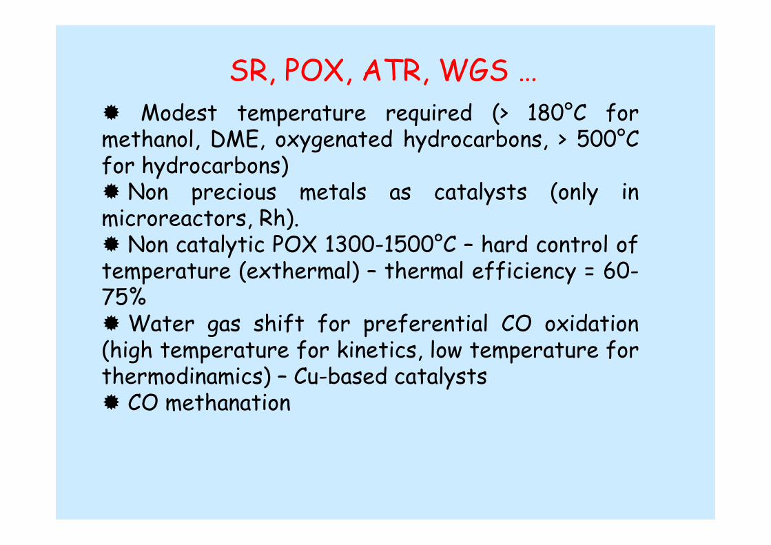
SR, POX, ATR, WGS …� Modest temperature required (> 180°C for methanol, DME, oxygenated hydrocarbons, > 500°C for hydrocarbons)� Non precious metals as catalysts (only in microreactors, Rh). � Non catalytic POX 1300-1500°C – hard control of temperature (exthermal) – thermal efficiency = 60-75% �Water gas shift for preferential CO oxidation (high temperature for kinetics, low temperature for thermodinamics) – Cu-based catalysts� CO methanation
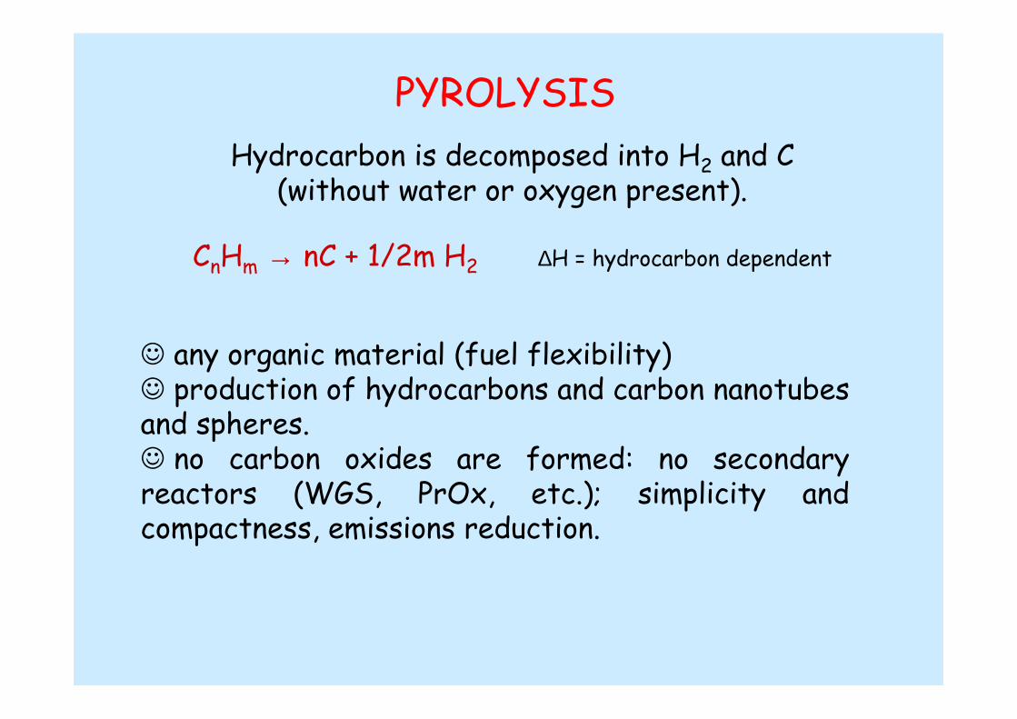
PYROLYSIS
Hydrocarbon is decomposed into H2 and C(without water or oxygen present).
☺ any organic material (fuel flexibility)☺ production of hydrocarbons and carbon nanotubesand spheres.☺ no carbon oxides are formed: no secondary reactors (WGS, PrOx, etc.); simplicity and compactness, emissions reduction.
CnHm → nC + 1/2m H2 ∆H = hydrocarbon dependent

PLASMA REFORMINGReactions = same as conventional reforming (POX, ATR, SR); Energy and free radicals are provided by a plasma (H, OH, and O radicals + electrons create conditions for reductive and oxidative reactions to occur)
☺ Overcomes many limitations of conventional techniques (cost anddeterioration of the catalysts, limitations on H2 production from heavy hydrocarbons)☺ Can operate at lower temperatures ☺ If no catalysts are used the process is highly sulfur tolerant.
� Electrical requirements � High electrode erosion Methane conversion as a function of power input
Empty reactor: plasmatron air = 0.4 g/s, fuel = 0.27 g/s, additional air = 0.7 g/s. Water addition, 0.2–0.5 g/s H2O added.Catalytic case: plasmatron air = 0.35 g/s, fuel = 0.25–0.5 g/s, additional air = 0.5–1 g/s. Water addition, 0.5–0.8 g/s water.
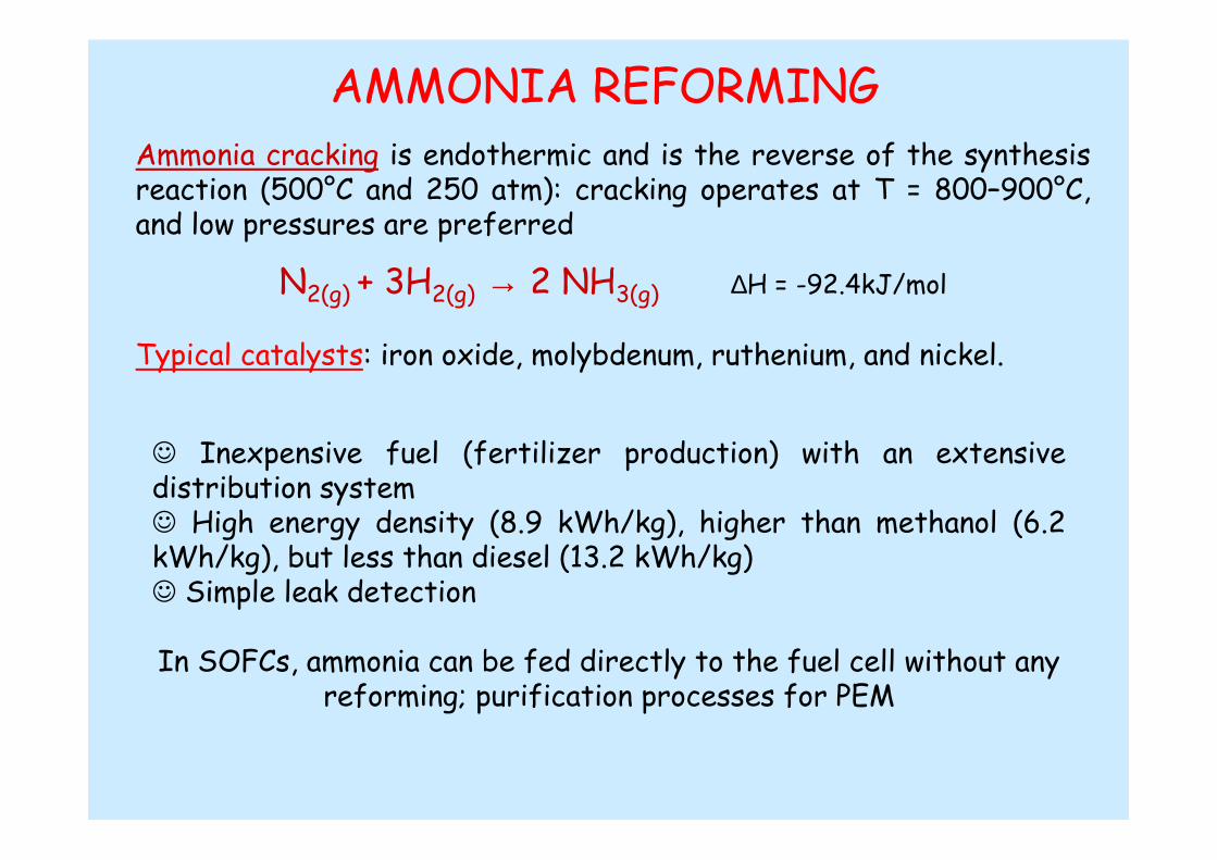
AMMONIA REFORMINGAmmonia cracking is endothermic and is the reverse of the synthesis reaction (500°C and 250 atm): cracking operates at T = 800–900°C, and low pressures are preferred
Typical catalysts: iron oxide, molybdenum, ruthenium, and nickel.
☺ Inexpensive fuel (fertilizer production) with an extensive distribution system ☺ High energy density (8.9 kWh/kg), higher than methanol (6.2 kWh/kg), but less than diesel (13.2 kWh/kg) ☺ Simple leak detection
In SOFCs, ammonia can be fed directly to the fuel cell without any reforming; purification processes for PEM
N2(g) + 3H2(g) → 2 NH3(g) ∆H = -92.4kJ/mol
NON-REFORMING H2 PRODUCTION
Hydrogen from biomassBiomass: the most likely renewable organic substitute topetroleum.
Second only to hydropower as a primary energy source amongrenewables.
animal wastes, municipal solid wastes, crop residues, short rotation woody crops, agricultural wastes, sawdust, aquatic plants,short rotation herbaceous species, waste paper, corn, …

NON-REFORMING H2 PRODUCTIONHydrogen from biomass
GasificationPyrolysis,Conversion to liquid fuels by supercritical extraction,Liquefaction,Hydrolysis followed by reformation
Bio-hydrogenDirect photolysisDark fermentationPhoto fermentationMicrobial electrolysis cell (MEC)

GASIFICATION
partial oxidation of the materials (biomass and coal) into a mixture of hydrogen, methane, carbon monoxide, carbon
dioxide, and nitrogen
☺ is very mature and commercially used
☺ with or without a catalyst
☺ + steam and/or oxygen = steam reforming and production of a syngas stream (H2 to CO ratio of 2:1), → Fischer-Tropsch higher hydrocarbons, or WGS for hydrogen production
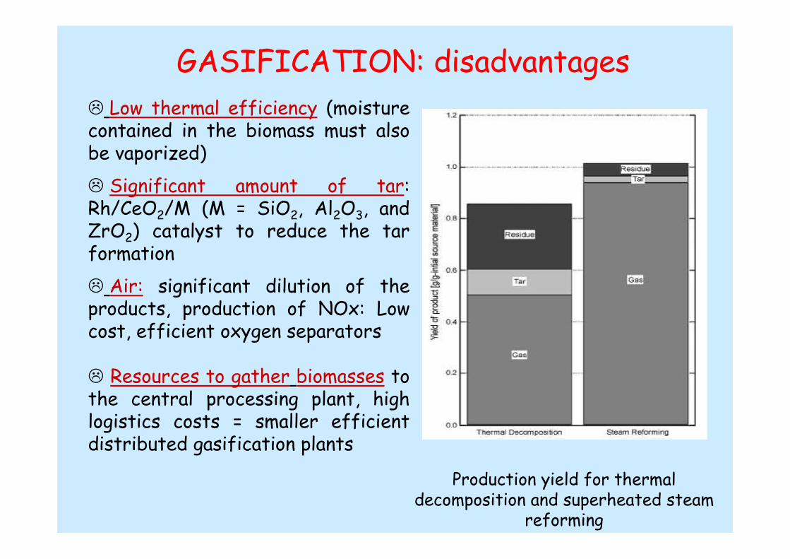
GASIFICATION: disadvantages� Low thermal efficiency (moisture contained in the biomass must also be vaporized)
� Significant amount of tar: Rh/CeO2/M (M = SiO2, Al2O3, and ZrO2) catalyst to reduce the tar formation
� Air: significant dilution of the products, production of NOx: Low cost, efficient oxygen separators
� Resources to gather biomasses to the central processing plant, high logistics costs = smaller efficient distributed gasification plants
Production yield for thermaldecomposition and superheated steam
reforming
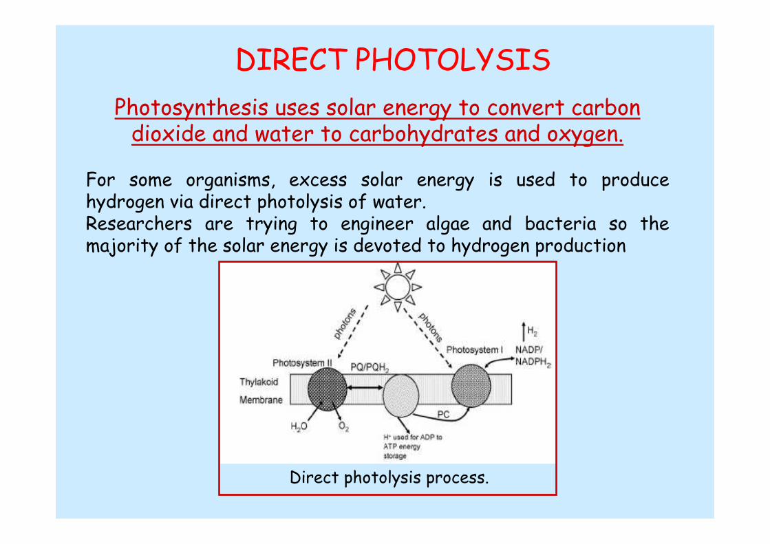
DIRECT PHOTOLYSIS
Photosynthesis uses solar energy to convert carbon dioxide and water to carbohydrates and oxygen.
For some organisms, excess solar energy is used to produce hydrogen via direct photolysis of water. Researchers are trying to engineer algae and bacteria so the majority of the solar energy is devoted to hydrogen production
Direct photolysis process.

DIRECT PHOTOLYSIS:Advantages and Disadvantages
☺ Primary feed is water
� Significant surface area to collect sufficient light� The microorganisms in addition to producing hydrogen, produce oxygen
Target: Continuous H2 production under aerobic conditions; 10 min of continuous operation by 2013
Stop of hydrogen production Significant safety and separation issues occur
To identify or engineer less oxygen sensitive organismsTo separate the hydrogen and oxygen cycles To change the ratio of photosynthesis to respiration
PHOTOFERMENTATIVE PROCESSES:photosynthetic bacterial H2 production
Cyanobacteria
Pigments (chlorophylls, carotenoids, and phycobilins) scavenge light energy which is transferred to membrane reaction centers converting
water into protons, electrons, and O2.The nitrogenase catalyst favorus the reaction the protons and
electrons with nitrogen and ATP to make ammonia, hydrogen and ADP
☺ Oxygen inhibits the nitrogenase: cyanobacteria separate nitrogen fixation and oxygen generation either spatially or temporally
� In nature the bacteria use H2 to fuel other energy requiring processes via the uptake hydrogenase enzyme.
� Nitrogenase enzyme is slow
Current efficiency is approximately 1.9%; theoretical limit = 68%
MICROBIAL ELECTROLYSIS CELL - MEC bioelectrochemically assisted microbial reactor (BEAMR),
Use electrohydrogenesis to directly convert biodegradable material into hydrogen.
Exoelectrogens microorganisms, decompose (oxidize) organic material and transfer electrons to the anode. The electrons combine at the cathode, after traveling through an external load, with protons and oxygen forming water.
� A MEC operates in anaerobic state and an external voltage is applied
The theoretical potential for hydrogen production at pH 7 is -0.61 V, (vs. Ag/AgCl). Exoelectrogens generate an anode potential of approximately Van = -0.5 V. Therefore the minimum applied potential is 0.11 V (applied voltage is > 0.3 V due to electrode overpotentials and ohmic resistance)
� The design of MEC systems initially used similar components as used in PEM fuel cells.
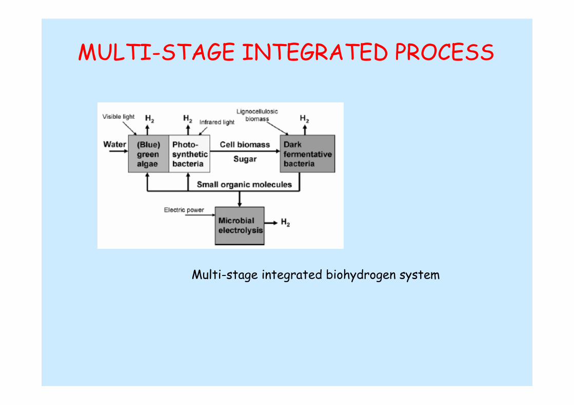
MULTI-STAGE INTEGRATED PROCESS
Multi-stage integrated biohydrogen system

Hydrogen production rate of different types of bio-hydrogen processes
215.8 mmol H2/l hMEC
1-14.758.2-121 mmol H2/l hDark fermentation
7470.16 mmol H2/l hPhoto-fermentation
17070.07 mmol H2/l hDirect photolysis
Bio-reactor volume (m3) for 5kW PEMFC
H2 synthesis rateBio-hydrogen system
NON-REFORMING H2 PRODUCTION
Hydrogen from water
ElectrolysisAlkaline electrolyzersProton exhange membrane electrolyzersSolid oxide electrolysis cells.
Thermochemical water splitting
Photoelectrolysis

ALKALINE ELECTROLYZER
Electrolyte = 30 wt% KOH or NaOHCathode = Ni with a catalytic coating, Pt
Anode = Ni or Co coated with metal oxides (Mn, W, Ru)
The liquid electrolyte is not consumed in the reaction, but must be replenished because of losses during H2 recovery. Current density = 100–300 mAcm-2
Efficiencies = 50–60%
Anode: 4OH- → O2 + 2H2O + 4 e-
Cathode: 4H2O + 4 e- → 2H2 + 4OH-
Total: 2H2O → 2H2 + O2

PROTON EXCHANGE MEMBRANE ELECTROLYZER
Electrolyte = H-Conducting polymer (Nafion)Cathode, Anode = Pt black, Ir, Ru, and Rh
Anode: 2H2O → O2 + 4H+ + 4 e-
Current density = 1600 mAcm-2
Efficiencies = 55–70%
Cathode: 4H+ + 4 e- → 2H2
Total: 2H2O → 2H2 + O2

SOLID OXIDE ELECTROLYSIS CELLS
Electrolyte = YSZ, Anode = Ni containing YSZ
Cathode = metal doped La-based oxides
Solid oxide electrolysis cells (SOEC) are essentially solid oxide fuel cells operating in reverse.
These systems replace part of the electrical energy required to split water with thermal energy
Efficiencies = 60, 85-90%
Energy demand for water and steam electrolysis
Anode: 2O2- → O2 + 4 e-
Cathode: 2H2O + 4 e- → 2H2 + 2O2-
Total: 2H2O → 2H2 + O2

THERMOCHEMICAL WATER SPLITTINGHeat alone is used to decompose water to hydrogen and oxygen; efficiencies close to 50% are achievable
�Water decomposition T = 2500°C, ☺ Chemical reagents to lower T; more than 300 water splitting cycles referenced in the literature
(1)Within the temperatures considered, the ∆G of the individualreactions must approach zero.
(2) The number of steps should be minimal.(3) Each individual step must have both fast reaction rates andrates which are similar to the other steps in the process.
(4) The reaction products cannot result in chemical-by-products, and any separation of the reaction products must be minimal in terms of cost and energy consumption.
(5) Intermediate products must be easily handled
Cycle Requirements

THERMOCHEMICAL WATER-SPLITTING CYCLES
• A thermochemical cycle: multi-step decomposition of water into hydrogen and oxygen using only heat.
• Thermochemical cycles are expected to be more efficient than electrolysis for H2 production
• Avoids greenhouse gas emission; allows complete recycling of chemicals.
• Solves the problem of long-term efficient thermal energy storage, by converting solar radiation in storable and transportable chemical fuels.
• The produced solar H2 fuel can be processed for heat and power generation, supplied as a clean energy carrier.

TWS: TWO STEPS CYCLES
• Involves reactions of metal-oxide redox pairs.
• First step (water-splitting): oxidation of the active redoxmaterial (reduced state of a metal oxide) by water steam produces hydrogen.
• Second step (driven by solar thermal energy), reduction of the metal oxide = active material regeneration with release of oxygen.
Schematicrepresentation of the two-step water-splitting
cycle

ADVANTAGES
(i) The maximum temperature of the cycle (1200 to 1800°C) is compatible with renewable solar thermal energy;
(ii) Water and heat are the only inputs, hydrogen and oxygen the only outputs;
(iii) H2 andO2 are produced separately;
(iv) The other chemicals and reagents are recycled in a closed cycle;
(v) The produced H2 is pure and can be directly processed, e.g., (PEMFC).
Switzerland (ETHZ, PSI), Germany (DLR, EC funded project ‘‘Hydrosol’’), France (CNRS-PROMES), USA (DOE funded projects) and Japan.

Cycle Criteria
(i) Within the temperatures considered the ∆G of the individual reactions must approach zero;
(ii) The number of steps must be minimal
(iii) Each individual step must have both fast reaction rates and rates which are similar to the other steps in the process
(iv) The reaction products cannot results in chemical-by-products and any separation of the reaction products must be minimal in terms of cost and energy consumption;
(v) Intermediate products must be easily handled

Volatile Metal Oxide CyclesVolatile ZnO/Zn: one of the best candidate for coupling
with a solar energy source.
� ZnO is decomposed near 1800°C in a solar reactor and Zn is recovered after quenching the product gases.
� Zn nanoparticles (size 70–100 nm) = yielding up to 70% H2Energy efficiency of ZnO/Zn cycle = 45%
ZnO/ZnZnO → Zn + ½ O2 T = 1800°C
Zn + H2O → ZnO + H2 T = 475°C
Totale: H2O → H2 + ½ O2
� The recombination of Zn and O2 is a parasitic reverse reaction limiting the Zn yield after the solar step (separation, quenching, fast cool).

THERMOCHEMICAL WATER SPLITTING:The most promising cycles
Ispra Mark-10
2H2O + SO2 + I2 + 4NH3 → 2NH4I + (NH4)2SO4 T = 50°C
2NH4I → 2NH3 + H2 + I2 T = 630°C
(NH4)2SO4 + Na2SO4 → Na2S2O7 + H2O + 2NH3 T = 400°C
Na2S2O7 → SO3 + Na2SO4 T = 550°C
SO3 → SO2 + ½ O2 T = 870°C
Total: H2O → H2 + ½ O2
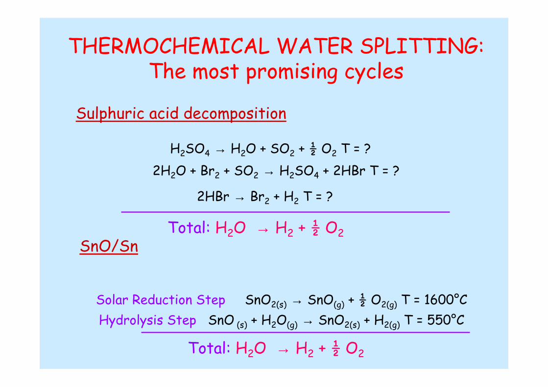
THERMOCHEMICAL WATER SPLITTING:The most promising cycles
Sulphuric acid decomposition
H2SO4 → H2O + SO2 + ½ O2 T = ?
2H2O + Br2 + SO2 → H2SO4 + 2HBr T = ?
2HBr → Br2 + H2 T = ?
Total: H2O → H2 + ½ O2SnO/Sn
Solar Reduction Step SnO2(s) → SnO(g) + ½ O2(g) T = 1600°C
Hydrolysis Step SnO (s) + H2O(g) → SnO2(s) + H2(g) T = 550°C
Total: H2O → H2 + ½ O2

H2-Production Technologies:Summary Table

Bibliography
1. J.D. Holladay, J. Hu, D.L. King, Y. Wang; Catalysis Today 139 (2009) 244–260Review: An overview of hydrogen production technologies2. S. Abanades, P. Charvin, F. Lemont, G. Flamant; International Journal of Hydrogen Energy, 33 (2008) 6021-6030 Novel two-step SnO2/SnO water-splitting cycle for solar thermochemical production of hydrogen