Embed Size (px)
Citation preview

Hydrogen Bonding and Stability of Hybrid Organic–Inorganic PerovskitesFedwa El-Mellouhi,*[a] Asma Marzouk,[a] El Tayeb Bentria,[a] Sergey N. Rashkeev,*[a]
Sabre Kais,[a, b, c] and Fahhad H. Alharbi[a, b]
Introduction
In the past few years, hybrid organic–inorganic perovskitesolar cells (PSCs)[1–3] have aroused great interest owing to thedramatic shot up of their power conversion efficiency, whichnow exceeds 20 %.[4] Although hybrid perovskites with compo-sition AMX3 [A = methylammonium (MA+) and/or formamidini-um (FA+) ; M = Sn2+ or Pb2 + ; and X = I� , Br � , and/or Cl�] wereknown for more than two decades,[5] it was recently recog-nized that they show outstanding performance in solar cell ap-plications and may be synthesized by relatively inexpensiveprocessing methods, such as spin-coating, dip-coating, andvapor deposition techniques.[6–8]
PSCs should be considered as a part of a more generalgroup of hybrid organic–inorganic framework materials formedby binding multi-dentate molecules to multi-coordinate metalcomplexes. These frameworks provide unlimited combinationsof physical and chemical properties that allow their use inmany applications,[9] including chemical sensing,[10] gas stor-
age,[11] catalysis,[12] optical and semiconductor devices, and bat-teries.[13] Some dense organic–inorganic frameworks exhibitwide range of ferroelectric and multiferroic properties.[14, 15]
High PSC power conversion efficiency in photovoltaics isa result of a combination of different properties, such as favor-able balance between strong absorption and long carrier life-times,[16, 17] outstanding transport,[18–20] and excellent fault toler-ance.[21] It was also suggested that defect tolerance in theseperovskites as well as in other organic–inorganic frameworksmay be related to the presence of van der Waals interactionsand hydrogen bonding.[3, 22, 23] Also, recent molecular dynamicssimulations indicate that in MAPbI3, I– anions form dynamicshort-lived hydrogen bonds with H atoms located on MA+
ions, which causes charge fluctuations, resulting in a significantincrease of the dielectric function.[24]
It is well known that MAPbI3 is unstable and sensitive to ex-ternal factors, such as moisture, UV exposure, and oxygen.[3, 25]
Poor crystal quality also contributes to stability issues[26] as wellas the dynamics of the polarized molecular cations.[27, 28] At thefundamental level, MAPbI3 suffers from intrinsic instability thatcan result in disorder and assist phase transitions. Recently, itwas computationally confirmed that this compound is thermo-dynamically unstable, and although a kinetic barrier that pre-vents its spontaneous decomposition to MAI and PbI2 exists, itis very low (i.e. , decomposition is unavoidable with time).[25]
It was experimentally shown that stability of PSC could besignificantly increased by mixing MA+ with FA+ and Cs+ cat-ions.[29, 30] Detailed structural investigations indicated that theresulting sample is not homogeneous, but consists of a mixtureof grains of different materials.[31] This granulated structure,however, may enhance the stability of the perovskite by limit-ing ion migration, which is assumed to be one of the instabili-ty causes.
In the past few years, the efficiency of solar cells based onhybrid organic–inorganic perovskites has exceeded the levelneeded for commercialization. However, existing perovskitessolar cells (PSCs) suffer from several intrinsic instabilities, whichprevent them from reaching industrial maturity, and stabilizingPSCs has become a critically important problem. Here we pro-pose to stabilize PSCs chemically by strengthening the interac-tions between the organic cation and inorganic anion of the
perovskite framework. In particular, we show that replacing themethylammonium cation with alternative protonated cationsallows an increase in the stability of the perovskite by formingstrong hydrogen bonds with the halide anions. This interactionalso provides opportunities for tuning the electronic statesnear the bandgap. These mechanisms should have a universalcharacter in different hybrid organic–inorganic framework ma-terials that are widely used.
[a] F. El-Mellouhi, A. Marzouk, E. T. Bentria, S. N. Rashkeev, S. Kais, F. H. AlharbiQatar Environment and Energy Research Institute (QEERI)Hamad Bin Khalifa UniversityP.O. Box 5825, Doha (Qatar)E-mail : [email protected]
[b] S. Kais, F. H. AlharbiCollege of Science and EngineeringHamad Bin Khalifa UniversityDoha (Qatar)
[c] S. KaisDepartment of Chemistry, Physics, and Birck Nanotechnology CenterPurdue UniversityWest Lafayette, Indiana 47907 (USA)
The ORCID identification number(s) for the author(s) of this article canbe found under http://dx.doi.org/10.1002/cssc.201600864.
This publication is part of a Special Issue focusing on the “Stability ofPerovskite Solar Cells & Devices”. A link to the issue’s Table of Contentswill appear here once it is complete.
ChemSusChem 2016, 9, 1 – 9 � 2016 Wiley-VCH Verlag GmbH & Co. KGaA, Weinheim1 &
These are not the final page numbers! ��These are not the final page numbers! ��
Full PapersDOI: 10.1002/cssc.201600864

Another possible way to stabilize the structure is to manipu-late the electronic coupling between the molecular cation Aand the MX6 octahedra of the perovskite structure. For exam-ple, 3 D MAPbI3 is composed of a network of corner-sharingPbI6 octahedra and molecular cations MA+ hosted betweenthe cages. The cohesion between PbI6 octahedra and MA+ ismainly owing to weak electrostatic interactions;[32] thus, theelectronic coupling between the octahedron and the cation isnegligible. This argument is supported by the fact that elec-tronic states owing to the MA+ orbitals are located several eVabove and below the band gap edges (formed mainly by 5 porbitals of iodine and 6 p orbitals of lead) and do not contrib-ute directly to the optical properties within the solar spectrumrange or electronic transport.[16, 33] Therefore, the resulting co-hesion is weak[3] as characterized by relatively small site Made-lung potential,[32, 34] which leads to chemical instability.
Another interesting consequence that originates from theseresults is the possibility to use cations and anions to tune theoptical and electrical properties by distorting the octahedralnetwork. Filip et al.[33] and Knutson et al.[35] utilized this conceptto tune the gap in 3 D and 2 D hybrid perovskites, respectively.
In this work, we employed density functional theory (DFT) toinvestigate pathways to strengthen the electronic coupling be-tween the molecular cation and MX6 octahedra to enhance thestability of hybrid perovskites. This stability enhancementmechanism is alternative to the approach based on mixing dif-ferent cations employed before,[29, 30] and focuses on atomic-scale changes within one unit cell of the perovskite material.Therefore, it potentially provides the possibility to grow higherquality crystal structures that are free of segregation on differ-ent phases and do not form granulated microstructures.
We found that the electronic coupling between the molecu-lar cation A+ and the MX6 octahedra may be manipulated intwo ways: (i) by modification of the molecular cation A+ , and(ii) by modification of the anion X� . For example, in the mostpopular PSC material MAPbI3, the MA+ cation containsa strong electronegative N atom. The electronegativity of I– israther low, so the H atoms are strongly bonded to the MA+ ,whereas their interaction with the PbI6 octahedron is fairlysmall. By replacing the nitrogen atom by a less electronegativeatom, the binding of the H atoms to the cation can be re-duced, thus enhancing the electronic coupling of H with PbI6
octahedron. It is also possible to change the whole MA+
cation by another protonated cation to obtain a similar result.Another possibility of strengthening electronic coupling is tosubstitute the I– anion with more electronegative elements(e.g. , F, Cl, and/or Br). Although the molecular cation designand substitution approach were considered in the past, this re-search was mainly focused on tuning the optoelectronic prop-erties through control of the band gap.[33, 34, 36] In this work, weprove that both cation and anion manipulations can be usedas a mechanism to enhance the stability of perovskite by ini-tiating stronger electronic coupling and electrostatic interac-tions.[37–40]
This approach is an attempt to employ mechanisms thatwere routinely utilized in other areas (e.g. , for the constructionof polymers and metal–organic frameworks[38, 41–43]) to the
world of PSC. We confirm the possibility of stabilizing hybridorganic–inorganic PSC materials using hydrogen bonds, orelectrostatic binding of hydrogen to a nearby highly electro-negative atom (e.g. , N, O, and F). This type of bonding occursin both inorganic (water) and organic (DNA and proteins) mol-ecules and plays an important role in determining the 3 Dstructures formed by these molecules (e.g. , a double helicalDNA structure).[44–46] Also, many polymers are strengthened byhydrogen bonds in their main chains.
Results and Discussion
Electronegativity Factor: Halide Substitution in MAPbI3
First, we investigated the role of electronegative anion inhybrid organic–inorganic perovskites. For this purpose we startwith the most popular PSC material, MAPbI3, and substitute I–
with halides having higher electronegativity (i.e. , Br, Cl, and F).For the sake of systematic analysis, we focused only of the tet-ragonal phase (b-phase) in which MAPbI3 crystallizes at roomtemperature.
To characterize the strength of hydrogen bonds, we em-ployed the recently developed noncovalent interactions (NCI)index that enables real-space visualization of both attractive(van der Waals and hydrogen bonding) and repulsive interac-tions based on the electron density.[47–49] This approach allowsdescription of the interplay between stabilizing and destabiliz-ing contributions that determine the stable minima on hydro-gen-bonding potential-energy surfaces. It relies on two scalarfields to map local bonding properties: 1) the electron density(1) and 2) the so-called reduced density gradient (RDG, s) de-fined as [Eq. (1)]:
s RDGð Þ ¼ 1
2 3pð Þ1=3
jr1j14=3
: ð1Þ
Three principle interaction regions define the real spacewhen combining the electron density and its gradient. Theregion of the non-interacting density tails is characterized bya high s and low 1. However, a low s and high 1 define the co-valent bonds region, where a low s and low 1 correspond toa non-covalent interaction. The non-covalent interactions arealso classified into attractive or repulsive according to the signof the second density eigenvalue (l2) of the electron-densityHessian (second derivative) matrix.
The calculations of the NCI index approach is not discussedin detail here. An important issue is that it allows differentiat-ing van der Waals interactions and hydrogen bonds by densi-ties at the corresponding bond critical point.[47] Typically, char-acteristic densities of van der Waals interactions are muchsmaller than densities at which hydrogen bonds appear. At thesame time, both van der Waals interactions and hydrogenbonds show negatives value l2 at the critical point, with a verylow l2 (very near zero) for van der Waals interactions. A de-tailed analysis of the interaction type can be performed byplotting diagrams of s vs. sign(l2)1. When there is an overlapbetween atomic orbitals, a trough in the NCI diagram appears.
ChemSusChem 2016, 9, 1 – 9 www.chemsuschem.org � 2016 Wiley-VCH Verlag GmbH & Co. KGaA, Weinheim2&
�� These are not the final page numbers!�� These are not the final page numbers!
Full Papers

The points forming this trough identify the interaction whenthey are mapped back to real space.[47]
In practice, the computational procedure of constructing anNCI diagram requires a grid-based representation of the self-consistent electron density, which is obtained from quantum-mechanical calculations. When the real-space region of interestis chosen, a regular grid is built to encompass it. At each gridpoint, 1 and s are numerically calculated and 1 is multiplied bythe sign of l2. Figure 1 shows NCI diagrams [s vs. sign(l2)1] forfour perovskites with the same organic cation and differenthalide anions (MAPbX3, X = I, Br, Cl, and F). For visualization ofthe NCI regions we also plot RDG isosurfaces in real space,which allows interpretation of different troughs in the NCI dia-gram as well as comparison of the strength of different NCIcomponents. Figure 2 shows RDG isosurfaces for the same fourperovskite materials.
The main feature of all NCI diagrams shown in Figure 1 isthe presence of several peaks at negative values of sign(l2)1corresponding to H···X hydrogen bonds of different lengths.The higher the electronegativity of the anion, the more nega-tive the values of the abscissa at which these peaks are located(i.e. , stronger hydrogen bonding). It is apparent that inMAPbI3, the H···I interaction is much weaker than H···F interac-tion in MAPbF3. In MAPbBr3, the two peaks at sign(l2)1=
�0.023 and �0.027 correspond to the shortest H···X bonds(2.34 and 2.42 �), whereas the third peak that appears athigher sign(l2)1=�0.012 relates to longer H···X bonds (2.89
and 2.90 �). In MAPbCl3, these peaks move to more negativevalues (�0.032, �0.031, and �0.021) and correspond to thebond lengths of 2.20, 2.22, and 2.41 �, respectively. In MAPbF3,the H···F bonds are even stronger and correspond to shorterbonds (1.68, 1.70, and 1.80 �).
The increase of hydrogen bond strength with increase ofthe anion electronegativity can also be seen from the NCI iso-surfaces in real space (Figure 2). When we move from I– to F–,the isosurface color in the region between the X and H fromthe NH3 group of the MA+ cation changes from green (for I) tobright red (for F), which corresponds to significant strengthen-ing of the attraction between H and X anion, where the elec-trons are more localized.
The chemical stability of the considered materials was alsoquantified by the reaction[50] and the hull[51–53] energies. The re-action energy is the difference between the total energy ofa reaction and reactants, whereas the hull energy is the differ-ence in formation energies and it effectively evaluates the sta-bility of a given compound against any linear combination.Whereas many possibilities for phase separation exist ; we usedthe separation into the most stable binary and ternary com-pounds based on phase diagrams constructed from the Materi-als’ Project database.[54]
Table 1 shows the reaction and hull energies for all consid-ered MAPbX3 (X = I, Br, Cl, and F) perovskites. One can say thatMAPbI3 and MAPbCl3 are marginally stable with reaction ener-gies ranged between �25 and �30 meVatom–1. So, the ther-
Figure 1. NCI diagrams [RDG, or s vs. sign(l2)1] for several methylammonium lead halides in tetragonal (b-) phase: A) CH3NH3PbI3, B) CH3NH3PbBr3,C) CH3NH3PbCl3, and D) CH3NH3PbF3. The dotted square corresponds to the region of the N�H···X bonds, at s = 0.3
ChemSusChem 2016, 9, 1 – 9 www.chemsuschem.org � 2016 Wiley-VCH Verlag GmbH & Co. KGaA, Weinheim3 &
These are not the final page numbers! ��These are not the final page numbers! ��
Full Papers

mal energy at room temperature can decompose the materi-als. At the same time, MAPbF3 should be considered as unsta-ble because the reaction and hull energies are slightly positive.At the same time, here the considered phase for MAPbF3 wastetragonal b-phase. Meanwhile, it is known that the cubicphase for this perovskite is more stable. Anyway, the bandgapin this material is above 3 eV, which makes it unsuitable ofsolar cells. However, it may be used in other optoelectronic ap-plications (e.g. , in some UV devices and sensors).
Manipulating electronic coupling by cation substitution
Now we consider the effect of cation substitution. For this pur-pose, we start with two halides widely used for PSC (i.e. ,MAPbI3 and MAPbBr3) and replace MA+ by another protonatedcation. Our target is to improve the stability of perovskite with-out deteriorating the energy bandgap that should be smallenough to guarantee a significant light absorption by the ma-terial at the solar spectra frequency range. For this purpose,
the cation must be small to ensure that a 3 D hybridperovskite structure is obtained and must not con-tain any elements with high electronegativity thatwill allow H-bonding with PbI6 or PbBr6 octahedronaccompanied by breaking the original bond betweenH and the protonated cation. There are many proton-ated cations fulfilling this condition and not limitedto the ones considered in this work, namely CH3PH3
+
, CH3SH2+ , and SH3
+ . The calculated gaps of thesematerials are shown in Table 1. Evidently, the bandg-ap is altered by cation substitution, but is still appro-priate for solar cells except for CH3PH3PbBr3, where itis reduced drastically owing to the emergence ofa state resulting from a bond formed between Br, thebridging H atom, and P,[55] which results in losing theelectrostatic balance and hence, weakening the elec-tronic coupling and chemical stability.
As explained in the Experimental Section, we alsogenerated phase diagrams for the relaxed structures.
These diagrams are then used for finding the decompositionroute to the most stable binary and ternary compounds. Thecalculated reaction and hull energies of these reactions arealso shown in Table 1. These energies are negative for all mate-rials with CH3PH3
+ , CH3SH2+ , and SH3
+ cations (the calculatedreaction and hull energies stand between �230 and �100 me-Vatom–1), except for the CH3PH3PbBr3 perovskite where bothreaction and hull energies are positive, thus confirming the in-stability of this material. This behavior is correlated with elon-gation of the bridging bond between the H atom and its do-nating atom in the cation compared to the standalone mole-cule. The relevant bridging bond is between the electron do-nating element in the cation (i.e. , P, N, S) and its farthest Hatom forming a bridge with the halide atom (i.e. , I, Br).
To understand the nature of instability in the CH3PH3PbBr3
material, we compared the NCI diagrams and NCI isosurfacesfor CH3PH3PbBr3 and CH3PH3PbI3 (Figure 3). Clearly, the peakscorresponding to hydrogen bonds between H atoms posi-tioned at the cation and halogen anion significantly shifted to
Figure 2. NCI isosurfaces in real space (perovskite tetragonal unit cell) for : A) CH3NH3PbI3, B) CH3NH3PbBr3, C) CH3NH3PbCl3, and D) CH3NH3PbF3. Atoms C(cyan), N (blue), H (light pink), I (magenta), Br (brown), Cl (green), and F (purple). The isosurfaces are generated at s = 0.3.
Table 1. Calculated bandgap (Eg), reaction (Ereact), formation (Eform), and hull energies(Ehull) ; bond length elongation (BLE) ;[a] tolerance factor (t) ; and octahedra tilting (q)/ro-tation (F) angles for different PSC tetragonal phase materials considered in this work.
Material Eg
[eV]Ereact
[eVatom–1]Eform
[eVatom–1]Ehull
[eVatom–1]BLE[%]
t q
[8]F
[8]
CH3NH3PbI3 1.79 �0.033 �0.579 �0.033 0.97 0.847 1.3 0.5CH3NH3PbBr3 1.92 �0.200 �0.684 �0.147 0.87 0.809 2.0 2.1CH3NH3PbCl3 2.30 �0.035 �0.924 �0.036 0.99 0.833 2.0 1.5CH3NH3PbF3 3.70 0.072 �1.757 0.066 1.50 0.800 2.7 0.5CH3PH3Pbl3 1.81 �0.108 �0.442 �0.110 2.14 0.970 0.5 0.0CH3PH3PbBr3 0.81 0.101 �0.337 0.099 10.71 0.806 4.2 0.5CH3SH2PbI3 1.55 �0.227 �0.434 �0.226 2.79 0.895 4.6 0.5CH3SH2PbBr3 1.95 �0.189 �0.540 �0.189 2.21 0.878 4.9 0.5SH3PbI3 1.73 �0.175 �0.442 �0.258 4.44 0.836 7.0 30.0SH3PbBr3 2.06 �0.386 �0.612 �0.229 2.55 0.863 8.4 17.0
[a] Bond length elongation between the bridging H and its associated atom in thecation within the crystal (e.g. , N, P, S) compared to its length in a standalone cation.
ChemSusChem 2016, 9, 1 – 9 www.chemsuschem.org � 2016 Wiley-VCH Verlag GmbH & Co. KGaA, Weinheim4&
�� These are not the final page numbers!�� These are not the final page numbers!
Full Papers

more negative values in CH3PH3PbBr3. Indeed, the shortestH···Br bond is 1.88 � in CH3PH3PbBr3 compared to the shortestH···I bond of 2.60 � in CH3PH3PbI3. Also, the dark brown colorof NCI isosurface for this bond in CH3PH3PbBr3 means a stron-ger hydrogen–halogen interaction compared to the moregreen color isosurface for this bond in CH3PH3PbI3.
From Table 1 it is clear that in the cases of MAPbI3 andMAPbBr3, the H···I and H···B bonds are barely stretched (by 0.97and 0.87 %, respectively). This is mainly a result of the highelectronegativity of the N atom, which keeps the bonded Hatoms bound tightly. It means that the contributions fromboth of them to the bridging states are small, implying thatthe associated H atom is highly localized within the cation andinteracts with the octahedron only weakly. The bridging P�Hand S�H bonds are elongated much further, and for the stablematerials, the elongation ranges between 2.14 and 4.44 %,which is mainly a result of the attraction of the H atom to thehalide and the bridge formation. So, the electronic densities ofP, S, and H are delocalized owing to elongation. This attractionbecomes even more substantial in CH3PH3PbBr3 where thebond is stretched by 10.71 %. In this particular case, the bridg-ing H atom is attracted significantly by the halide, whichbreaks the balance around it. We attribute this phenomena tothe electronegativity difference between Br (2.96) and P(2.19).[56]
Further understanding of the effects of enhanced electroniccoupling between the cation and the octahedron requiresa close look at the electronic structure. Table 2 contains nor-malized participation ratios (relative contributions to the normof the wavefunction from atoms of a given sort) of the bridg-ing states between the cation and octahedron for MAPbX3 andCH3PH3PbX3 (X = I and Br). For each material, the bridging statewas identified by analyzing the projected density of states
(PDOS) in the vicinity of the valence band edge. First, theenergy point near the top of the valence band was found atwhich the PDOS for the electron donating atom of the cation(i.e. , N, P, or S) has a maximum. Second, the electronic band(bands) contributing to this peak was (were) identified, andcontributions to this band (bands) from H and halide atomswere also analyzed. For MAPbI3 and MAPbBr3, the contribu-tions of MA+ are deep in the valence and conduction bands.There are nearly no signs for interactions between the cationand PbI6 and PbBr6 octahedra. This is severely altered whenthe MA+ cation is replaced by the suggested protonated cat-ions CH3PH3
+ , CH3SH2+ , and SH3
+ . In particular, forCH3PH3PbBr3, several molecular states caused by the enhancedelectronic coupling appear at the top of the valence band. Inthe extreme case of very strong interaction between hydrogenof the cation with halide atom [reflected in the participationratio (PR), which indicates that main contribution to the bridg-ing state is given by the Br atoms] , it results in emergingstates occupying the top of the valance band and considerablyshifting its edge as in the case of CH3PH3PbBr3. In such a case,one can say that electronic coupling between the cation andthe halides in the octahedron lost a balance.
Figure 3. NCI diagrams [s vs. sign(l2)1] for A) CH3PH3PbI3, and B) CH3PH3PbBr3 in tetragonal (b) phase and C–D) NCI isosurfaces for the same materials. AtomsC (cyan), P (olive green), H (light pink), I (magenta), and Br (brown). The dotted line corresponds to the region of the P�H···X bonds, at s = 0.3.
Table 2. The normalized participation ratios for the bridging states be-tween the cations and the octahedron.
Material N or P H I or Br
CH3NH3PbI3 0.018 0.009 0.973CH3NH3PbBr3 0.049 0.005 0.946CH3PH3Pbl3 0.068 0.034 0.898CH3PH3PbBr3 0.694 0.056 0.250
ChemSusChem 2016, 9, 1 – 9 www.chemsuschem.org � 2016 Wiley-VCH Verlag GmbH & Co. KGaA, Weinheim5 &
These are not the final page numbers! ��These are not the final page numbers! ��
Full Papers

Tolerance factor and structural and chemical stability ofhybrid perovskites
The tolerance factor [t, Eq. (2)] was introduced to evaluateionic size mismatches that the perovskite structure will tolerateuntil transformation into another structure,
t ¼ rA þ rXð Þ=ffiffiffi
2p
rB þ rXð Þ, ð2Þ
where ri are the radii of the ions in the perovskite ABX3, andi = A, B, and X, respectively.[57] This is a semi-empirical relation-ship that continues to be widely used as a guiding principle inthe study of perovskite structures. It is widely accepted thatcubic perovskite structure is stable for the values of t in therange 0.9–1.0, while values of 0.80–0.89 correspond to distort-ed perovskites that can be classified by using the concept ofoctahedral tilting.[58, 59] Below 0.80, other structures, such as theilmenite-type (FeTiO3), are more stable owing to similar sizes ofthe cations A and B, and values larger than 1 lead to hexago-nal structures where layers of face-sharing octahedra are intro-duced into the structure.[58]
Tilting and rotation of the octahedra play an important rolein stabilizing the perovskite structures (Figure 4). They gener-ate lower-symmetry distorted structures, in which the coordi-nation numbers of A cations, B cations, or both are reduced.For example, the TiO6 octahedron rotation and tilt angles arelikely to be responsible for the metal–insulator transition inoxide superlattices.[60] Octahedral rotation and tilt angles arealso related to structural and magnetic phase transitions in dif-ferent perovskite materials.[61] It was experimentally shown thattunable optical bandgaps in metal–halide perovskites could beachieved by controlling the degree of the PbI6 octahedral tilt-ing through the steric size of the molecular cation.[33] In partic-ular, the bandgap can be reduced by decreasing the degree ofthe octahedral tilting, which can be achieved by adjusting thedegree of the hydrogen-bonding interactions between the hal-ides and H atoms bonded to the MA group.[33, 36]
We calculated t and octahedron tilt/rotation angles for allconsidered perovskites (Table 1). A crucial point here is the def-
inition of ionic radii of protonated cations containing severalatoms. An attempt to make several steps in this direction wasconsidered in Ref. [58] where an effective molecular cationradius was defined. Also, it was suggested that the shape ofsome anions could be approximated by cylinders.
In this work, we used different approach. If one assumesthat ionic spheres are touching, there is no need to defineeach of them individually. Instead, one needs to find the aver-aged (rA + rX) and (rB + rX) only. Assuming that the center of mo-lecular cation X is positioned in its center of mass, we couldcalculate both quantities from the atomic structure of the ma-terial that is geometrically relaxed by employing some first-principles calculations method.
Table 1 shows that for nearly all considered perovskites, thetolerance factor lies in the range between 0.8 and 0.9, whichindicates that distorted perovskite structure with some tilt androtation angles (q and F) is stable for them. The only excep-tion is CH3PH3PbI3 with t = 0.97, which means that cubic perov-skite structure should be preferable for this compound. Actual-ly, the rotation angle for this perovskite is zero while the tiltangle is only 0.58, which is lower than for any other perovskiteconsidered here (i.e. , the structure is nearly cubic).
An interesting observation is that for two perovskites (unsta-ble CH3PH3PbBr3 and marginally stable MAPbF3), the value of tis very close to 0.8, which means that these perovskites havecations (A and B) of similar size so transformations to otherstructures may be possible. However, taking into accounta very limited character of the tolerance factor concept, wewould avoid making any conclusions here. Another interestingobservation is the observance of very high rotation angles forperovskites based on the SH3
+ cation. The reason for that be-havior could be a very anisotropic character of this molecularcation so accommodating such species in the perovskite struc-ture could become a very complicated problem.
Conclusions
We show the possibility to chemically stabilize the hybrid or-ganic–inorganic perovskites by replacing methylammoniummolecular cation (MA+) with other protonated cations(CH3PH3
+ , CH3SH2+ , and SH3
+) to enhance the electronic cou-pling between the cation and the perovskite structure octahe-drons. We also show that similar effects could be reached bysubstitution of widely used halide anions (I� , Br �) by halideanions with higher electronegativity (Cl� , F�). At the sametime, the bandgap energy could be maintained within therange suitable for solar cells applications. In practice, thesearch of new cations and anions can be performed by analyz-ing the electronegativity of the material constituents and theresulting electrostatic interactions.
For each material, we checked the stability in several differ-ent ways including analyzing: (i) the reaction, formation, andhull energies; (ii) calculating the tolerance factor and octahe-dron tilt/rotation angles; and (iii) checking electronic balancefor bridge states using normalized participation ratios. In par-ticular, it was found that to be stable, the material should havenegative reaction and formation energies, the tolerance factor
Figure 4. Tilted and rotated view of the corner-shared BX6 octahedra in theABX3 perovskite structure: a) along a [1 0 0] direction showing the octahedraltilting angle q, and b) along a [0 0 1] direction showing clearly the octahedralrotation angle F. Atoms A (yellow), B (green), and X (magenta).
ChemSusChem 2016, 9, 1 – 9 www.chemsuschem.org � 2016 Wiley-VCH Verlag GmbH & Co. KGaA, Weinheim6&
�� These are not the final page numbers!�� These are not the final page numbers!
Full Papers

should lie in the stability range, and electronic coupling be-tween the halides in the octahedron and protonated cationsshould be balanced. If any of these criteria is violated, the ma-terial most likely is unstable with respect to some structuraltransformation and unsuitable for protovoltaic and other opto-electronic applications. In addition to the protonated cations(CH3PH3
+ , CH3SH2+ , and SH3
+) considered in this work, weexpect that several other molecular cations with enhancedcoupling and stability could be used.
Experimental Section
First principles calculations are used to compute the electronicstructure and to estimate the stability of the proposed materials.DFT calculations are done using the projected augmented wave(PAW) method as built in the Vienna ab initio Simulation Package(VASP).[62] All calculations were performed using spin polarized gen-eralized gradient approximation (GGA) with the Perdew–Burke–Ernzerhof (PBE) parametrization for the exchange and correlationenergy of interacting electrons.[63] The energy cutoff for the plane-wave basis set was set to 520 eV and a 8 � 8 � 8 Monkhorst–Pack k-point mesh was employed. Long-range van der Waals interactionshave been taken into account through the Tkatchenko and Schef-fler (TS) scheme.[64] The convergence of the final forces is set to0.01 eV ��1.
The participation ratio is obtained directly from VASP output. Forthe stability calculations, the phase diagrams are generated for thegiven stoichiometry using PyMatGen with the Material Project (MP)DataBase.[54] Then, we construct the decomposition route to themost stable binary and ternary compounds and calculate the reac-tion and hull energies.[51–53] A material is considered stable if the re-action and hull energies are negative. To consider the calculationerrors, the stability is considered marginal if the magnitude of thecalculated energy is below 100 meVatom–1.[65]
To characterize the strength of hydrogen bonds as well as othernoncovalent interactions, we used noncovalent interactions (NCI)index that enables real-space visualization of both attractive (vander Waals and hydrogen bonding) and repulsive interactions basedon properties of the electron density.[47–49] This approach allows thedescription of the interplay between stabilizing and destabilizingcontributions that determine stable minima on hydrogen-bondingpotential-energy surfaces. The hydrogen bonds are visualizedusing the NCIPLOT technique. NCI isosurfaces correspond to s = 0.3and the color scale is �0.04< sign(l2)1<0.04
The simulation box used in the calculations is based on the48 atoms unit cell (4 unit formula) where both the halides and cat-ions are subsequently substituted followed by a full geometricaloptimization using DFT. The simulation box is optimal to allow theoctahedral rotations and tilts and hence, a better assessment ofthe stability. For preparation of the NCI diagrams and isosurfaces,calculations on a very fine mesh within a subregion positionedinside the simulation box (a 3 D cube targeting one organic mole-cule and its first neighbor halides) were performed.
Acknowledgements
We are extremely grateful for the Research Computing Center inTexas A&M University at Qatar and SHAHEEN Supercomputer atKing Abdullah University of Science and Technology (KAUST),
Saudi Arabia, where the calculations were conducted. This workis supported by the Qatar National Research Fund (QNRF)through the National Priorities Research Program (NPRP8-090-2-047).
Keywords: density functional theory · hydrogen bonding ·perovskite · solar cells · stability
[1] H.-S. Kim, S. H. Im, N.-G. Park, J. Phys. Chem. C 2014, 118, 5615 – 5625.[2] S. D. Stranks, H. J. Snaith, Nat. Nanotechnol. 2015, 10, 391 – 402.[3] J. Berry, T. Buonassisi, D. A. Egger, G. Hodes, L. Kronik, Y.-L. Loo, I. Lubo-
mirsky, S. R. Marder, Y. Mastai, J. S. Miller, D. B. Mitzi, Y. Paz, A. M. RAppe,I. Riess, B. Rybtchinski, O. Stafsudd, V. Stevanovic, M. F. Toney, D. Zitoun,A. Kahn, D. Ginley, D. Cahen, Adv. Mater. 2015, 27, 5102 – 5112.
[4] W. S. Yang, J. H. Noh, N. J. Jeon, Y. C. Kim, S. Ryu, J. Seo, S. I. Seok, Sci-ence 2015, 348, 1234 – 1237.
[5] D. B. Mitzi, C. A. Feild, W. T. A. Harrison, A. M. Guloy, Nature 1994, 369,467 – 469.
[6] J. Burschka, N. Pellet, S.-J. Moon, R. Humphry-Baker, P. Gao, M. K. Na-zeeruddin, M. Gr�tzel, Nature 2013, 499, 316 – 319.
[7] M. Liu, M. B. Johnston, H. J. Snaith, Nature 2013, 501, 395 – 398.[8] G. E. Eperon, S. D. Stranks, C. Menelaou, M. B. Johnston, L. M. Herz, H. J.
Snaith, Energy Environ. Sci. 2015, 7, 982 – 988.[9] S. L. James, Chem. Soc. Rev. 2003, 32, 276 – 288.
[10] L. E. Kreno, K. Leong, O. K. Farha, M. Allendorf, R. P. Van Duyne, J. T.Hupp, Chem. Rev. 2012, 112, 1105 – 1125.
[11] R. E. Morris, P. S. Wheatley, Angew. Chem. Int. Ed. 2008, 47, 4966 – 4981;Angew. Chem. 2008, 120, 5044 – 5059.
[12] A. U. Czaja, N. Trukhan, U. Muller, Chem. Soc. Rev. 2009, 38, 1284 – 1293.[13] A. K. Cheetham, C. N. R. Rao, Science 2007, 318, 58 – 59.[14] D. Di Sante, A. Stroppa, P. Jain, S. Picozzi, J. Am. Chem. Soc. 2013, 135,
18126 – 18130.[15] D.-F. Weng, Z.-M. Wang, S. Gao, Chem. Soc. Rev. 2011, 40, 3157 – 3181.[16] C. Motta, F. El-Mellouhi, S. Kais, N. Tabet, F. Alharbi, S. Sanvito, Nat.
Commun. 2015, 6, 7026.[17] R. E. Brandt, V. Stevanovic, D. S. Ginley, T. Buonassisi, MRS Commun.
2015, 5, 265 – 275.[18] S. N. Rashkeev, F. El-Mellouhi, S. Kais, F. H. Alharbi, Sci. Rep. 2015, 5,
11467.[19] A. Pecchia, D. Gentilini, D. Rossi, M. Auf der Maur, A. Di Carlo, Nano Lett.
2016, 16, 988 – 992.[20] Q. Dong, Y. Fang, Y. Shao, P. Mulligan, J. Qiu, L. Cao, J. Huang, Science
2015, 347, 175 967 – 970.[21] M. Gr�tzel, Nat. Mater. 2014, 13, 838 – 842.[22] D. B. Mitzi in Progress in Inorganic Chemistry (Ed. : K. D. Karlin), Wiley,
Hoboken, NJ, USA, 1999, pp. 1 – 121.[23] J. C. Tan, A. K. Cheetham, Chem. Soc. Rev. 2011, 40, 1059 – 1080.[24] T. Hakamata, K. Shimamura, F. Shimojo, R. K. Kalia, A. Nakano, P. Vashish-
ta, Sci. Rep. 2016, 6, 19599.[25] Y.-Y. Zhang, S. Chen, P. Xu, H. Xiang, X.-G. Gong, A. Walsh, S.-H. Wei, In-
trinsic instability of the hybrid halide perovskite semiconductorCH3NH3PbI3, arXiv preprint, arXiv:1506.01301 [cond-mat.matrl-sci] , 2015.
[26] M. I. Saidaminov, V. Adinolfi, R. Comin, A. L. Abdelhady, W. Peng, I.Dursun, M. Yuan, S. Hoogland, E. H. Sargent, O. M. Bakr, Nat. Commun.2015, 6, 8724.
[27] A. Mattoni, A. Filippetti, M. Saba, P. Delugas, J. Phys. Chem. C 2015, 119,17421 – 17428.
[28] M. A. Carignano, A. Kachmar, J. Hutter, J. Phys. Chem. C 2015, 119,8991 – 8997.
[29] D. P. McMeekin, G. Sadoughi, W. Rehman, G. E. Eperon, M. Saliba, M. T.Hçrantner, A. Haghighirad, N. Sakai, L. Korte, B. Rech, M. B. Johnston,L. M. Herz, H. J. Snaith, Science 2016, 351, 151 – 155.
[30] M. Saliba, T. Matsui, J.-Y. Seo, K. Domanski, J.-P. Correa-Baena, M. K. Na-zeeruddin, S. M. Zakeeruddin, W. Tress, A. Abate, A. Hagfeldt, M. Gr�tzel,Energy Environ. Sci. 2016, 9, 1989 – 1997.
[31] J. S. Yun, J. Seidel, J. Kim, A. M. Soufiani, S. Juang, J. Lau, N. J. Jeon, S. I.Seok, M. A. Green, A. Ho-Baillie, Adv. Energy Mater. 2016, 6, 1600330.
[32] A. Walsh, J. Phys. Chem. C 2015, 119, 5755 – 5760.
ChemSusChem 2016, 9, 1 – 9 www.chemsuschem.org � 2016 Wiley-VCH Verlag GmbH & Co. KGaA, Weinheim7 &
These are not the final page numbers! ��These are not the final page numbers! ��
Full Papers

[33] M. R. Filip, G. E. Eperon, H. J. Snaith, F. Giustino, Nat. Commun. 2014, 5,5757.
[34] J. M. Frost, K. T. Butler, F. Brivio, C. H. Hendon, M. van Schilfgaarde, A.Walsh, Nano Lett. 2014, 14, 2584 – 2590.
[35] J. L. Knutson, J. D. Martin, D. B. Mitzi, Inorg. Chem. 2005, 44, 4699 – 4705.[36] A. Amat, E. Mosconi, E. Ronca, C. Quarti, P. Umari, Md. K. Nazeeruddin,
M. Gr�tzel, F. De Angelis, Nano Lett. 2014, 14, 3608 – 3616.[37] R. Bertani, P. Sgarbossa, A. Venzo, F. Lelj, M. Amati, G. Resnati, T. Pilati, P.
Metrangolo, G. Terraneo, Coord. Chem. Rev. 2010, 254, 677 – 695.[38] B. Li, S.-Q. Zang, L. Y. Wang, T. C. W. Mak, Coord. Chem. Rev. 2016, 308,
1 – 21.[39] N. Leblanc, M. Allain, N. Mercier, E. Cariati, Cryst. Growth Des. 2011, 11,
5200 – 5205.[40] F. El-Mellouhi, E.-T. Bentria, S. N. Rashkeev, S. Kais, F. H. Alharbi, Enhanc-
ing Intrinsic Stability of Hybrid Perovskite Solar Cell by Strong, yet Bal-anced, Electronic Coupling, arXiv preprint, arXiv:1604.06875 [cond-mat.mtrl-sci] , 2016.
[41] G. R. Desiraju, J. Am. Chem. Soc. 2013, 135, 9952 – 9967.[42] L. C. Gilday, S. W. Robinson, T. A. Barendt, M. J. Langton, B. R. Mullaney,
P. D. Beer, Chem. Rev. 2015, 115, 7118 – 7195.[43] S. Schamnad, S. Chakraborty, Chem. Phys. Lett. 2015, 622, 28 – 33.[44] E. T. Kool, Annu. Rev. Biophys. Biomol. Struct. 2001, 30, 1 – 22.[45] J. Sponer, J. Leszczynski, P. Hobza, J. Biomol. Struct. Dyn. 1996, 14, 117 –
135.[46] J. Sponer, J. Leszczynski, P. Hobza, Biopolymers 2001, 61, 3 – 31.[47] J. Contreras-Garc�a, W. Yang, E. R. Johnson, J. Phys. Chem. A 2011, 115,
12983 – 12990.[48] A. Otero-de-la-Roza, E. R. Johnson, J. Contreras-Garcıa, Phys. Chem.
Chem. Phys. 2012, 14, 12165 – 12172.[49] J. Contreras-Garc�a, E. R. Johnson, S. Keinan, R. Chaudret, J.-P. Piquemal,
D. N. Beratan, W. Yang, J. Chem. Theory Comput. 2011, 7, 625 – 632.[50] G. Hautier, S. P. Ong, A. Jain, C. J. Moore, G. Ceder, Phys. Rev. B 2012, 85,
155208.
[51] S. Atahan-Evrenk, A. Aspuru-Guzik in Prediction and calculation of crystalstructures—Methods and applications, Topics in Current Chemistry,Vol. 345 (Eds. : S. Atahan-Evrenk, A. Aspuru-Guzik), Springer, Berlin, 2014,pp. 95 – 138.
[52] G. Trimarchi, A. J. Freeman, A. Zunger, Phys. Rev. B 2009, 80, 092101.[53] M. d’Avezac, A. Zunger, Phys. Rev. B 2008, 78, 064102.[54] A. Jain, S. Ping Ong, G. Hautier, W. Chen, W. Davidson Richards, S.
Dacek, S. Cholia, D. Gunter, D. Skinner, G. Ceder, K. A. Persson, APLMater. 2013, 1, 011002.
[55] F. El-Mellouhi, E.-T. Bentria, S. N. Rashkeev, S. Kais, F. H. Alharbi, Hydrogenbonding : A mechanism for tuning electronic and optical properties ofhybrid organic-inorganic frameworks, arXiv preprint, arXiv:1604.07150[cond-mat.mtrl-sci] , 2016.
[56] W. M. Haynes, CRC Handbook of Chemistry and Physics, CRC Press, BocaRaton, 2014.
[57] V. M. Goldschmidt, Naturwissenschaften 1926, 14, 477 – 485.[58] G. Kieslich, S. Sun, A. K. Cheetham, Chem. Sci. 2014, 5, 4712 – 4715.[59] A. M. Glazer, Acta Crystallogr. Sect. B 1972, 28, 3384 – 3392.[60] J. M. Rondinelli, N. A. Spaldin, Phys. Rev. B 2010, 82, 113402.[61] F. El-Mellouhi, E. N. Brothers, M. J. Lucero, I. W. Bulik, G. E. Scuseria, Phys.
Rev. B 2013, 87, 035107.[62] G. Kresse, J. Furthmuller, Phys. Rev. B 1996, 54, 11169 – 11186.[63] J. P. Perdew, K. Burke, M. Ernzerhof, Phys. Rev. Lett. 1996, 77, 3865 –
3868.[64] A. Tkatchenko, R. A. Di Stasio, R. Car, M. Scheffler, Phys. Rev. Lett. 2012,
108, 236402.[65] S. Korbel, M. A. Marques, S. Botti, J. Mater. Chem. C 2016, 4, 3157 – 3167.
Received: June 29, 2016
Published online on && &&, 0000
ChemSusChem 2016, 9, 1 – 9 www.chemsuschem.org � 2016 Wiley-VCH Verlag GmbH & Co. KGaA, Weinheim8&
�� These are not the final page numbers!�� These are not the final page numbers!
Full Papers
FULL PAPERS
F. El-Mellouhi,* A. Marzouk, E. T. Bentria,S. N. Rashkeev,* S. Kais, F. H. Alharbi
&& –&&
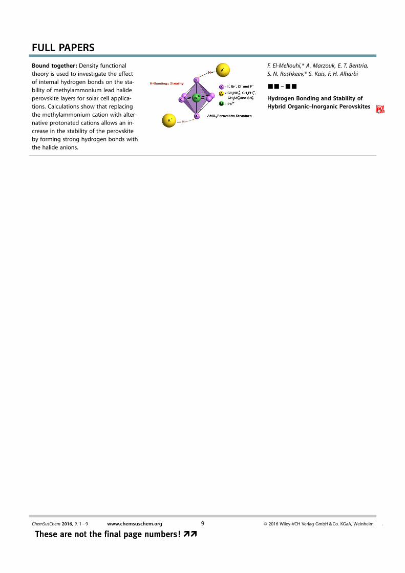
Hydrogen Bonding and Stability ofHybrid Organic–Inorganic Perovskites
Bound together: Density functionaltheory is used to investigate the effectof internal hydrogen bonds on the sta-bility of methylammonium lead halideperovskite layers for solar cell applica-tions. Calculations show that replacingthe methylammonium cation with alter-native protonated cations allows an in-crease in the stability of the perovskiteby forming strong hydrogen bonds withthe halide anions.
ChemSusChem 2016, 9, 1 – 9 www.chemsuschem.org � 2016 Wiley-VCH Verlag GmbH & Co. KGaA, Weinheim9 &
These are not the final page numbers! ��These are not the final page numbers! ��