Embed Size (px)
Citation preview

HYDROCAL 1005 Manual for Installation and Operation Edition 01.2011
HYDROCAL1005
Gas-in-Oil Analysis System with
Transformer Monitoring Functions
Manual for installation and operation

HYDROCAL 1005 Manual for Installation and Operation Page 2/111
Copyright MTE Meter Test Equipment AG All rights reserved.
The contents of this manual are subject to change without notice.
All efforts have been made to ensure the accuracy of this publication but MTE Meter Test Equipment AG can assume no responsibility for any errors Customs tariff number: or their consequences 9027.1010
HYDROCAL 1005 Manual for Installation and Operation Page 1/111
Summary
1. General ....................................................................................................................................... 4
2. Mounting of HYDROCAL1005 unit ............................................................................................ 5
2.1 Locations for installation of HYDROCAL1005 ....................................................................... 5
2.2 Security precautions for installation ...................................................................................... 6
2.3 Preparation for installation .................................................................................................... 8
2.3.1 Power supply for the unit ............................................................................................... 8
2.3.2 Requested tools: ........................................................................................................... 8
2.4 Installation of the HYDROCAL1005 unit ............................................................................... 8
2.5 Electrical Installation of HYDROCAL1005 unit .................................................................... 11
2.6 Completion of Installation ................................................................................................... 12
3. Hardware components of HYDROCAL 1005 .......................................................................... 14
3.1 Front view of HYDROCAL1005 .......................................................................................... 14
3.2 Rear side of HYDROCAL1005 unit ..................................................................................... 15
3.3 Connections on the measuring and controller card ............................................................. 17
3.4 Measurement and extraction Components ......................................................................... 22
4. Software on HYDROCAL unit ................................................................................................. 24
4.1 General information ............................................................................................................ 24
4.2 Description of Gas measurement Process ......................................................................... 24
4.3. Operation Cycles ................................................................................................................ 25
4.3.1. Zero measurement ...................................................................................................... 25
4.3.1.1 Safety function and error observation for Zero measurement cycle ...................... 25
4.3.2 Depression .................................................................................................................. 26
4.3.2.1. Safety function and error observation for depression cycle .................................. 26
4.3.3. Leak detection ............................................................................................................. 27
4.3.3.1. Safety function and error observation for leak detection cycle .............................. 27
4.3.4. Filling to level 1 ............................................................................................................ 28
4.3.4.1. Safety function and error observation for filling to level 1 cycle............................. 28
4.3.5. Degassing ................................................................................................................... 29
4.3.5.1. Safety function and error observation for degassing cycle .................................... 29
4.3.6. Filling to level 2 ............................................................................................................ 30
4.3.6.1. Safety function and error observation for filling to level 2 cycle............................. 30
4.3.7. Measurement .............................................................................................................. 31
4.3.7.1. Safety function and error observation for measurement cycle .............................. 31
4.3.8. Flushing ....................................................................................................................... 32
4.3.8.1. Safety function and error observation for flushing cycle ....................................... 32
4.3.9. Draining ....................................................................................................................... 33
4.3.9.1. Safety function and error observation for draining cycle ....................................... 33
4.3.10. Wait ......................................................................................................................... 34
4.3.10.1. Safety function and error observation for wait cycle ............................................. 34
4.4 Operation of HYDROCAL1005 by its keyboard .................................................................. 35
4.4.1 Contrast Set-up ........................................................................................................... 35
4.5 Main menu .......................................................................................................................... 36
4.6 Extraction Menu .................................................................................................................. 37
4.7 Display of stored „Gas-in-oil“measuring values................................................................... 37
4.7.1 Graphic display................................................................................................. 37
4.7.2 Table presentation............................................................................................ 38
HYDROCAL 1005 Manual for Installation and Operation Page 2/111
4.8 Status of alarms ...................................................................................................... 39
4.8.1 Acknowledgment of alarms ......................................................................................... 39
4.9 Device set – up ........................................................................................................ 40
4.9.1 Menu Transformer data setup .......................................................................... 41
4.9.1.1. DGA Adjustment: Input of correction factor .............................................................. 41
4.9.1.1 Hot Spot calculation .................................................................................. 42
4.9.1.2 Ageing Rate / Loss of Life ......................................................................... 44
4.9.2 Configuration of analogue outputs.................................................................... 45
4.9.3 Configuration of analogue inputs (external sensors) ........................................ 45
4.9.4 Configuration of alarms and digital outputs ...................................................... 48
4.9.5 Unit Setup ........................................................................................................ 51
4.9.5.1 Digital Output Test..................................................................................... 52
4.9.5.2 Device options .......................................................................................... 52
4.9.5.2.1. Configuration of user settings ......................................................................... 53
4.9.5.3 Date. Time & Clock Settings ..................................................................... 53
4.9.5.4 Configuration of the communication .......................................................... 55
4.9.5.5 Ethernet setup ........................................................................................... 56
4.9.5.6 Alert SMS setup ........................................................................................ 57
4.9.5.7 Internal modem setup ............................................................................... 58
4.9.5.8 RS 232 / RS 485 setup ......................................................................................... 59
4.9.5.9 MODBUS .............................................................................................................. 66
5. Windows Software HydroSoft ................................................................................................ 76
5.1 Purpose of the program ...................................................................................................... 76
5.2 Remarks for use of this operation handbook ...................................................................... 76
5.3 Requirements to the PC ..................................................................................................... 76
5.4 Installation .......................................................................................................................... 77
5.4.1 Microsoft .NET .NET Framework 1.1 Redistributable .................................................. 77
5.4.2 Microsoft Data Access Components ............................................................................ 77
5.4.3 Adaptation of installation ............................................................................................. 78
5.5 Functions of HydroSoft program ......................................................................................... 78
5.6 Start of program ................................................................................................................. 78
5.7 Preparation / rename of a new customer list....................................................................... 79
5.8 Opening a new transformer station ..................................................................................... 80
5.9 Opening a file for a new transformer .................................................................................. 80
5.9.1 Modem settings ........................................................................................................... 82
5.9.2 RS232 interface settings ............................................................................................. 82
5.10 Settings of HYDROCAL1005 unit ....................................................................................... 82
5.10.1 Alert Setup................................................................................................................... 83
5.10.2 External sensors (see also chapter 4.7.3) ................................................................... 86
HYDROCAL 1005 Manual for Installation and Operation Page 3/111
5.10.3 Alert SMS Setup .......................................................................................................... 87
5.10.4 Input of DGA Level Adjustment ................................................................................... 89
5.10.5 Analog Output Setup ................................................................................................... 90
5.10.6 Digital Output Setup .................................................................................................... 91
5.10.7 Device Setup (Clock settings) ...................................................................................... 91
5.10.5.1. Ethernet ................................................................................................................ 92
5.10.5.2. Modbus-TCP ........................................................................................................ 93
5.10.5.3. MODBUS .............................................................................................................. 93
5.11 Data transmission from / to the HYDROCAL1005 unit ........................................................ 93
5.12 View of results .................................................................................................................... 96
5.12.1 Sensor selection .......................................................................................................... 96
5.12.2 Time range selection ................................................................................................... 96
5.12.3 Result window ............................................................................................................. 97
5.12.4 Print and export of results ............................................................................................ 97
5.13 View of alarm status ........................................................................................................... 98
5.13.1 Alarm selection ............................................................................................................ 98
5.13.2 Time range selection ................................................................................................... 98
5.13.3 Alarm window .............................................................................................................. 99
5.13.4 Status of alarms .......................................................................................................... 99
5.13.5 Print and export of results ............................................................................................ 99
5.14 Online Sensors ................................................................................................................. 100
6. RS 485 Wiring ........................................................................................................................ 101
7. HYDROSOFT Scheduler ........................................................................................................ 102
7.1 General ............................................................................................................................ 102
7.2 Scheduler ......................................................................................................................... 102
7.2.1 Configuring a Transformer for automatic History Data Update .................................. 102
7.2.1.1 Connection Scheduler Dialog ............................................................................. 103
7.2.2 Scheduler Status Visualization .................................................................................. 103
7.2.2.1 Status Icons ....................................................................................................... 103
7.2.2.2 Transformer ........................................................................................................ 104
7.2.2.3 Station ................................................................................................................ 104
7.2.2.4 Customer ............................................................................................................ 104
7.2.2.5 Example ............................................................................................................. 104
7.2.3 HydroSoft and the Windows Task Scheduler ............................................................ 105
7.2.3.1 Command Line Options for Windows Task Scheduler ........................................ 106
7.2.3.2 IdleClose ............................................................................................................ 106
7.2.3.3 Minimized ........................................................................................................... 106
7.2.4 Internal Operation ...................................................................................................... 106
7.2.5 Data Directory Lock ................................................................................................... 107
8. Technical data HYDROCAL1005 ........................................................................................... 108
9. Dimensional drawings HYDROCAL1005 .............................................................................. 110
HYDROCAL 1005 Manual for Installation and Operation Page 4/111
1. General The HYDROCAL 1005 is a permanently-installed multi-gas-in-oil analysis system with transformer monitoring functions. It allows for the individual measurement of moisture and the key gases hydro-gen (H2), carbon monoxide (CO), acetylene (C2H2) and ethylene (C2H4) dissolved in transformer oil.
As hydrogen (H2) is involved in nearly every fault of the isolation system of power transformers and carbon monoxide (CO) is a sign of an involvement of the cellulosic / paper isolation the presence and increase of acetylene (C2H2) and ethylene (C2H4) further classifies the nature of a fault as overheat-ing, partial discharge or high energy arcing. The device can serve as a compact transformer monitor-ing system by the integration / connection of other sensors present on a transformer via its analog inputs:
5 analog outputs 0/4-20mADC
4 analog inputs 0/4-20 mADC (Option)
6 analog inputs 0/4-20 mADC +20% / 0-80 VAC +20% (option) configurable by jumpers
It is further equipped with digital outputs for the transmission of alarms or the execution of control functions (e. g. control of a cooling system of a transformer):
5 digital relay outputs
5 digital opto-coupler outputs (Option)
Key Advantages
Hydrogen (H2), Carbon monoxide (CO), acetylene (C2H2) and ethylene (C2H4) measurement
Moisture-in-oil measurement
Communication interfaces ETHERNET 10/100 Mbit/s (copper-wired or fibre-optical) and RS 485 to support proprietary communication protocols and to be open / prepared for substation commu-nication protocols IEC 61850, MODBUS, DNP 3 etc.
Optional on-board GSM and analog modems for remote communication
6 analog AC current inputs for the connection of capacitive HV bushing sensors for HV bushing monitoring applications
The present operating instructions are divided in the following sections:
Instructions for mounting the HYDROCAL 1005 unit (chapter 2)
Hardware components of HYDROCAL 1005 (chapter 3)
Description of software of the HYDROCAL 1005 unit (chapter 4)
Description of Windows software HydroSoft (chapter 5)
RS 485 Wiring (chapter 6)
New HydroSoft Scheduler functions (chapter 7)
Technical Data of HYDROCAL 1005 (chapter 8)
HYDROCAL 1005 dimensional drawings (chapter 9)
HYDROCAL 1005 Manual for Installation and Operation Page 5/111
2. Mounting of HYDROCAL1005 unit
2.1 Locations for installation of HYDROCAL1005
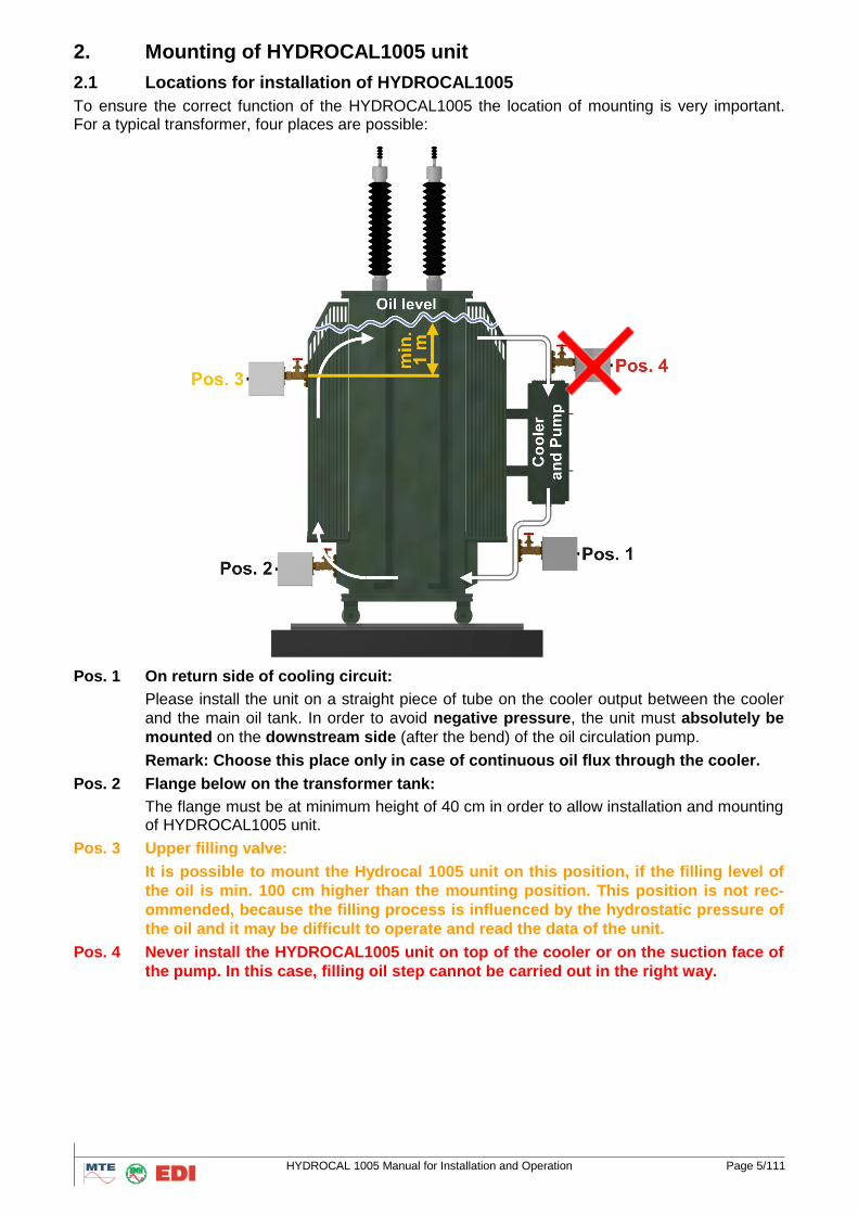
To ensure the correct function of the HYDROCAL1005 the location of mounting is very important. For a typical transformer, four places are possible:
Pos. 1 On return side of cooling circuit:
Please install the unit on a straight piece of tube on the cooler output between the cooler
and the main oil tank. In order to avoid negative pressure, the unit must absolutely be
mounted on the downstream side (after the bend) of the oil circulation pump.
Remark: Choose this place only in case of continuous oil flux through the cooler.
Pos. 2 Flange below on the transformer tank:
The flange must be at minimum height of 40 cm in order to allow installation and mounting of HYDROCAL1005 unit.
Pos. 3 Upper filling valve:
It is possible to mount the Hydrocal 1005 unit on this position, if the filling level of
the oil is min. 100 cm higher than the mounting position. This position is not rec-
ommended, because the filling process is influenced by the hydrostatic pressure of
the oil and it may be difficult to operate and read the data of the unit.
Pos. 4 Never install the HYDROCAL1005 unit on top of the cooler or on the suction face of
the pump. In this case, filling oil step cannot be carried out in the right way.
HYDROCAL 1005 Manual for Installation and Operation Page 6/111
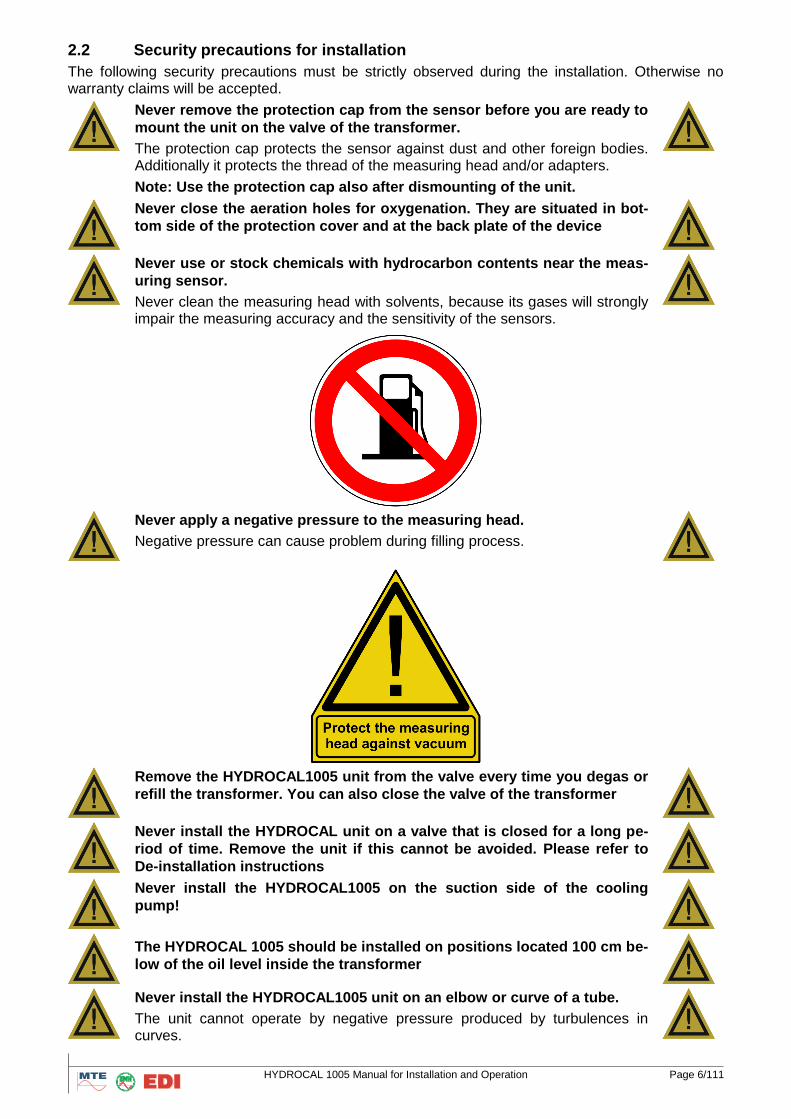
2.2 Security precautions for installation
The following security precautions must be strictly observed during the installation. Otherwise no warranty claims will be accepted.
Never remove the protection cap from the sensor before you are ready to
mount the unit on the valve of the transformer.
The protection cap protects the sensor against dust and other foreign bodies. Additionally it protects the thread of the measuring head and/or adapters.
Note: Use the protection cap also after dismounting of the unit.
Never close the aeration holes for oxygenation. They are situated in bot-
tom side of the protection cover and at the back plate of the device
Never use or stock chemicals with hydrocarbon contents near the meas-
uring sensor.
Never clean the measuring head with solvents, because its gases will strongly impair the measuring accuracy and the sensitivity of the sensors.
Never apply a negative pressure to the measuring head.
Negative pressure can cause problem during filling process.
Remove the HYDROCAL1005 unit from the valve every time you degas or
refill the transformer. You can also close the valve of the transformer
Never install the HYDROCAL unit on a valve that is closed for a long pe-
riod of time. Remove the unit if this cannot be avoided. Please refer to
De-installation instructions
Never install the HYDROCAL1005 on the suction side of the cooling
pump!
The HYDROCAL 1005 should be installed on positions located 100 cm be-
low of the oil level inside the transformer
Never install the HYDROCAL1005 unit on an elbow or curve of a tube.
The unit cannot operate by negative pressure produced by turbulences in curves.

HYDROCAL 1005 Manual for Installation and Operation Page 7/111
Never install or remove the HYDROCAL1005 without opening first the
aeration screw.
Never use galvanized fittings or valves to mount the HYDROCAL1005
unit.
Galvanized fittings or valves can react with oil; this will produce incorrect measuring values.
Never clean the HYDROCAL1005 unit with high pressure cleaning
equipment.
High pressure cleaning equipment used to clean transformers can seriously damage the HYDROCAL1005 unit.
Never use a chaining key tool for mounting.
Use of such tools can damage the surface of the measuring head and the threads. Please use an adjustable thin spanner for 1 ½“.
Attention!!!
Faulty or inappropriate handling of the sensor head like malfunction by
negative pressure, paint or solvent liquids make the warranty invalid.

HYDROCAL 1005 Manual for Installation and Operation Page 8/111
2.3 Preparation for installation
Before installation, a visual inspection of the unit must be carried out. Remove the protection cover and check visually the components. All cables and tubes must be connected.
2.3.1 Power supply for the unit
The HYDROCAL1005 unit requires an auxiliary power supply of 110 / 230V close to the unit. The power needed is max. 350 VA.
2.3.2 Requested tools:
Long Allen key, size 4 for aeration screw
Bucket, oil absorber, cleaning rag
Teflon-band
Drill / screw driver
Digital multimeter
Tin spanner M55 or adjustable tin spanner of 1 ½“ for valve and fittings To seal the thread of the measuring head, either Teflon band (minimum 4 to 5 layers must be ap-plied) or an O-Ring must be used.
2.4 Installation of the HYDROCAL1005 unit
Attention!!!
Mount the unit horizontally on the valve. The aeration screw must be in
the 12 o’clock position.
Please mount the HYDROCAL1005 unit on a valve with full opening (full bore valve) or a ball valve with an internal thread of 1½” (DIN ISO 228: G 1½) . The HYDROCAL unit has a 1½’’ thread (Di-mensional drawings, see. chapter 8). As an option a valve with NPT 1½ standard can also be used.
A good oil flux should exist on the mounting location. If necessary, use a reduction piece (adapter).
It is recommended to mount the HYDROCAL 1005 unit to valve with a union- or sleeve nut. In this case the device has not to be turned to fix during the installation. An O-ring should be used as seal-ing.
In case there exist strong vibrations on the mounting valve, the valve should be relieved by a sup-port.
Then mount the unit according to the following steps:
HYDROCAL 1005 Manual for Installation and Operation Page 9/111
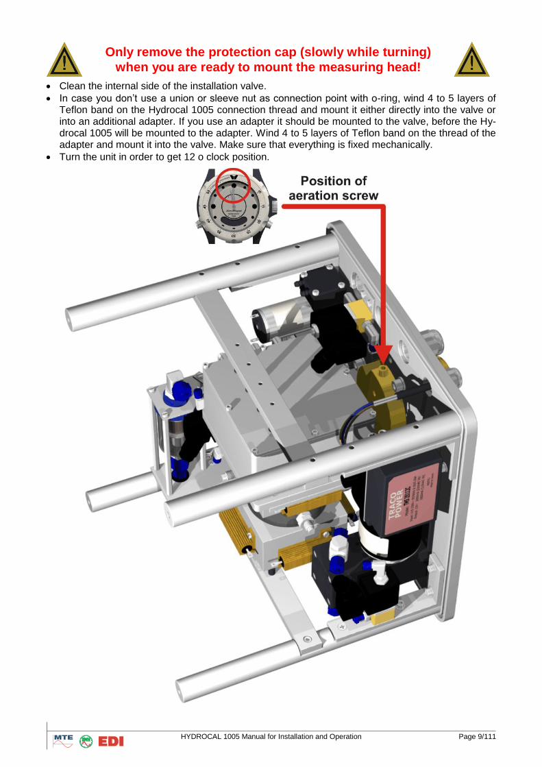
Only remove the protection cap (slowly while turning)
when you are ready to mount the measuring head!
Clean the internal side of the installation valve.
In case you don’t use a union or sleeve nut as connection point with o-ring, wind 4 to 5 layers of Teflon band on the Hydrocal 1005 connection thread and mount it either directly into the valve or into an additional adapter. If you use an adapter it should be mounted to the valve, before the Hy-drocal 1005 will be mounted to the adapter. Wind 4 to 5 layers of Teflon band on the thread of the adapter and mount it into the valve. Make sure that everything is fixed mechanically.
Turn the unit in order to get 12 o clock position.
HYDROCAL 1005 Manual for Installation and Operation Page 10/111
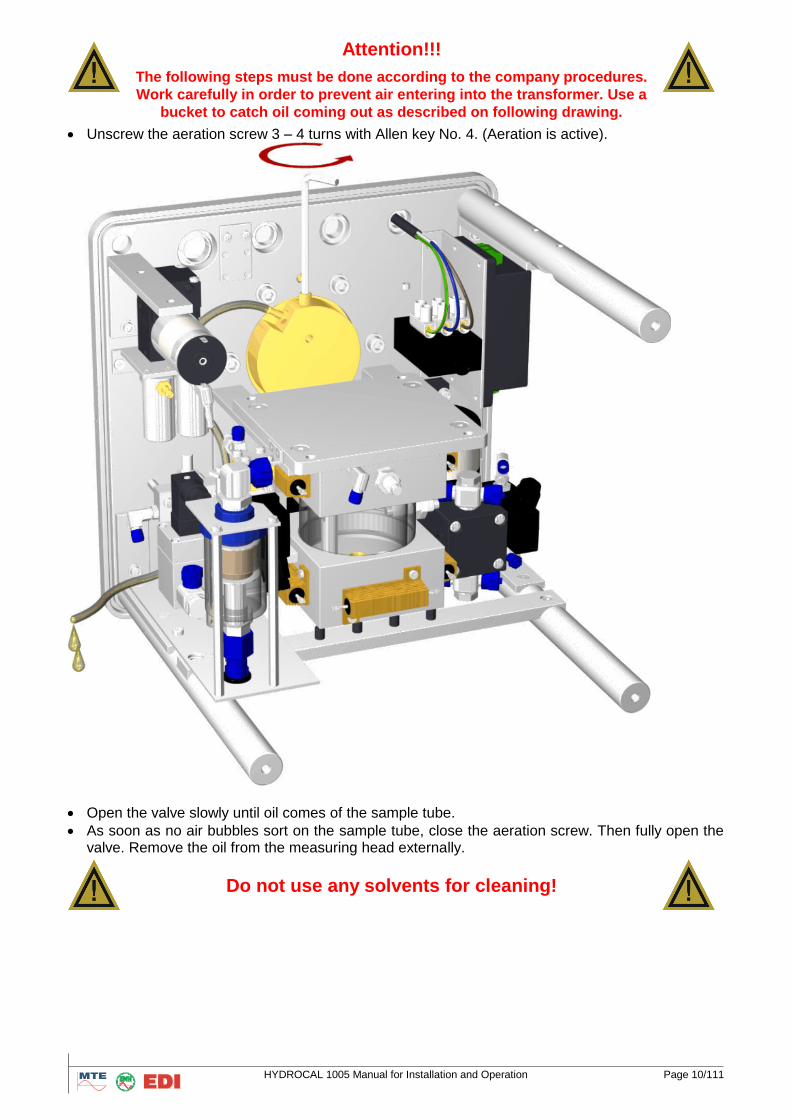
Attention!!!
The following steps must be done according to the company procedures.
Work carefully in order to prevent air entering into the transformer. Use a
bucket to catch oil coming out as described on following drawing.
Unscrew the aeration screw 3 – 4 turns with Allen key No. 4. (Aeration is active).
Open the valve slowly until oil comes of the sample tube.
As soon as no air bubbles sort on the sample tube, close the aeration screw. Then fully open the valve. Remove the oil from the measuring head externally.
Do not use any solvents for cleaning!

HYDROCAL 1005 Manual for Installation and Operation Page 11/111
2.5 Electrical Installation of HYDROCAL1005 unit
Use steel protected cables for power supply, alarm-cables and communication cables and con-nect them to the appropriate connectors.
Recommendations for main supply cable:
Mains supply cable (3-wire)
(1) Phase 230VAC 20% (2) Neutral (3) Protection Earth
Wire : 1,5mm2
If optional GSM Modem is used, GSM antenna must be connected to Hydrocal as above draw-
ing:
Recommendations for alarm and external sensor cables:
Cable Specification (or equivalent) Type: e.g. Ölflex FD855CP
Cable : 13,3mm (of external cable)
Wire : 0,5mm2 (of 16 intern. wires)
Connect the power supply to the HYDROCAL1005 unit. The display shows the specified condi-tions confirming that the HYDROCAL1005 is functioning correctly.
o Brown (L) o Blue (N) o Green - yellow (PE)
HYDROCAL 1005 Manual for Installation and Operation Page 12/111
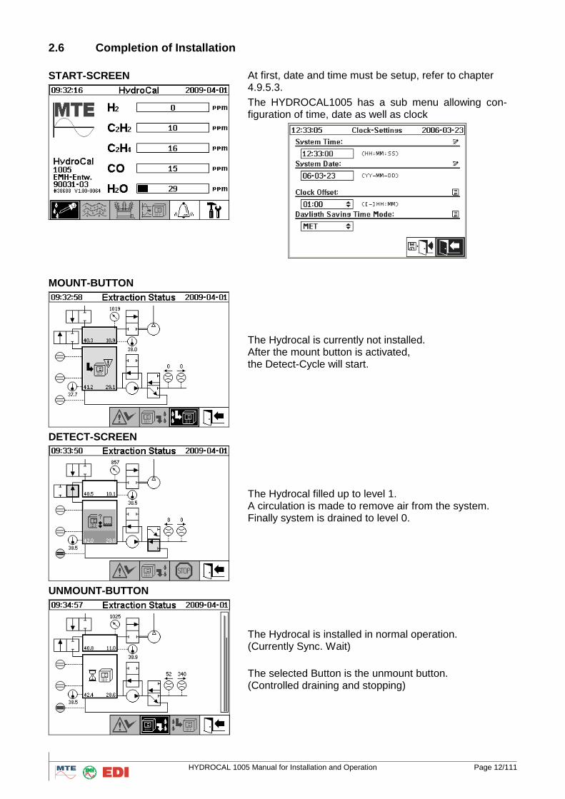
2.6 Completion of Installation
START-SCREEN
At first, date and time must be setup, refer to chapter 4.9.5.3.
The HYDROCAL1005 has a sub menu allowing con-figuration of time, date as well as clock
MOUNT-BUTTON
The Hydrocal is currently not installed. After the mount button is activated, the Detect-Cycle will start.
DETECT-SCREEN
The Hydrocal filled up to level 1. A circulation is made to remove air from the system. Finally system is drained to level 0.
UNMOUNT-BUTTON
The Hydrocal is installed in normal operation. (Currently Sync. Wait)
The selected Button is the unmount button. (Controlled draining and stopping)

HYDROCAL 1005 Manual for Installation and Operation Page 13/111
Then, if everything is working correctly put the housing in correct position and secure it with the knurled thumbscrews.
The measuring cycle of the HYDROCAL1005 unit is synchronized on the hour mark; this means the first measuring value is available approx. 2, 22 or 42 min. after the hour mark and can be read on the display.
After first start-up, in all cases date and time have to be checked on the HYDROCAL1005 display and eventually have to be adjusted manually in clock settings (chapter 3.7.5.2) or with HydroSoft (chapter 4.10.7).
HYDROCAL 1005 Manual for Installation and Operation Page 14/111
3. Hardware components of HYDROCAL 1005
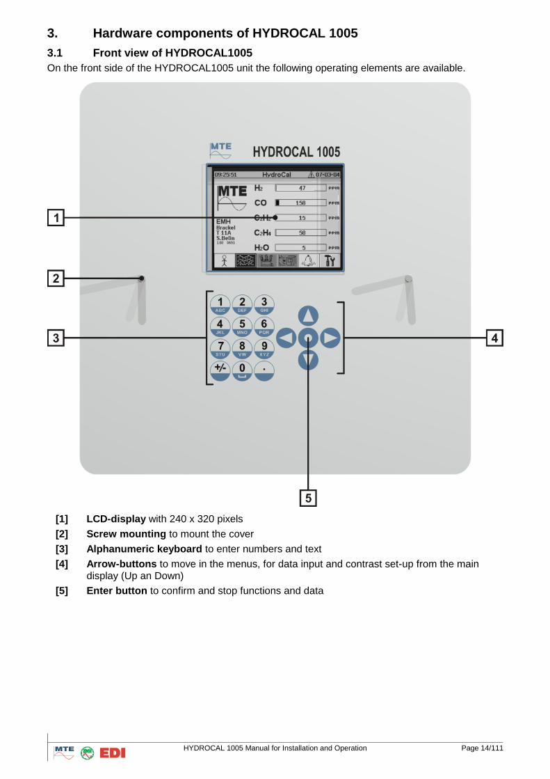
3.1 Front view of HYDROCAL1005
On the front side of the HYDROCAL1005 unit the following operating elements are available.
[1] LCD-display with 240 x 320 pixels
[2] Screw mounting to mount the cover
[3] Alphanumeric keyboard to enter numbers and text
[4] Arrow-buttons to move in the menus, for data input and contrast set-up from the main display (Up an Down)
[5] Enter button to confirm and stop functions and data
HYDROCAL 1005 Manual for Installation and Operation Page 15/111
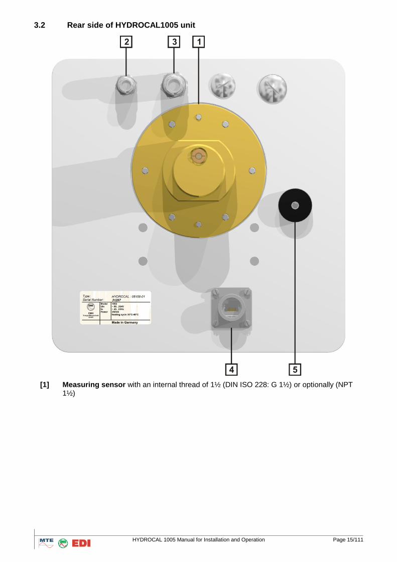
3.2 Rear side of HYDROCAL1005 unit
[1] Measuring sensor with an internal thread of 1½ (DIN ISO 228: G 1½) or optionally (NPT 1½)

HYDROCAL 1005 Manual for Installation and Operation Page 16/111
[2] Entrance for power supply 88 VACmin … 276 VACmax Optional: 88 VDCmin … 390 VDCmax
max. 350 VA, 50/60 Hz
Then, power supply must be connected as follow :
o Brown (L) o Blue (N) o Green - yellow (PE)
[3] System outlet for digital and analogue inputs and outputs
Communication outlet for communication via analogue or GSM/GPRS-modem
[4] ETHERNET connector
[5] Gas Air Outlet
HYDROCAL 1005 Manual for Installation and Operation Page 17/111
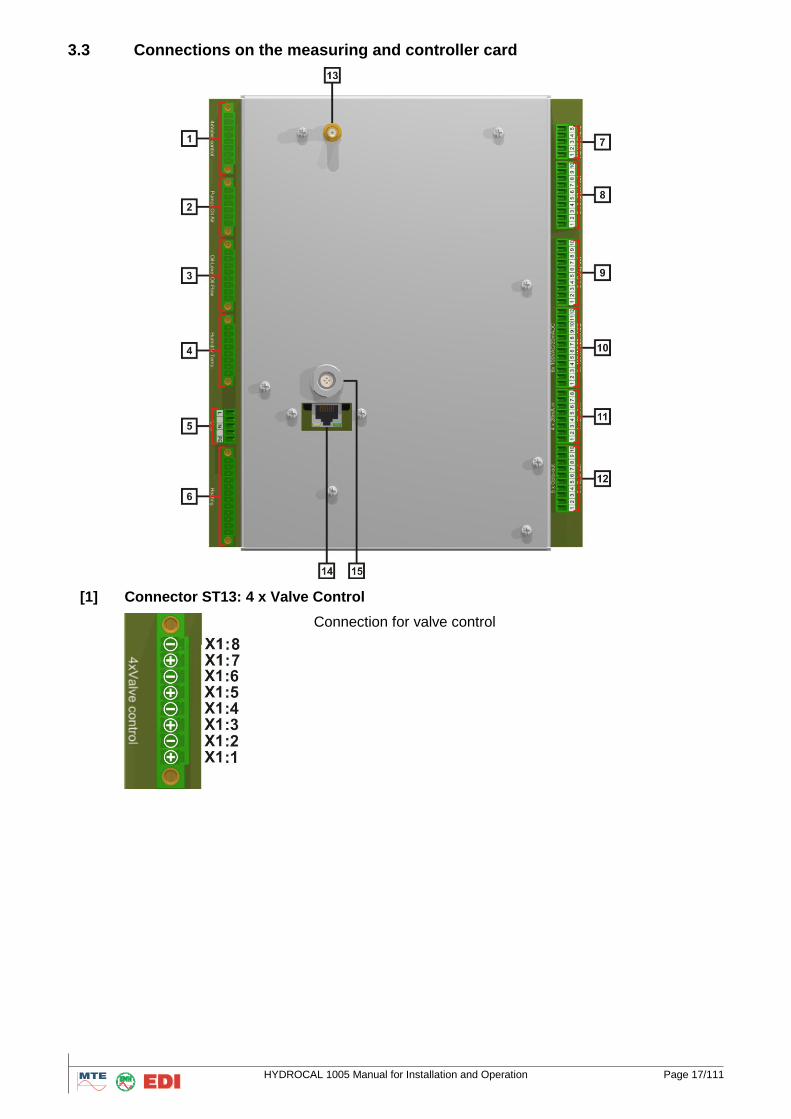
3.3 Connections on the measuring and controller card
[1] Connector ST13: 4 x Valve Control
Connection for valve control
HYDROCAL 1005 Manual for Installation and Operation Page 18/111
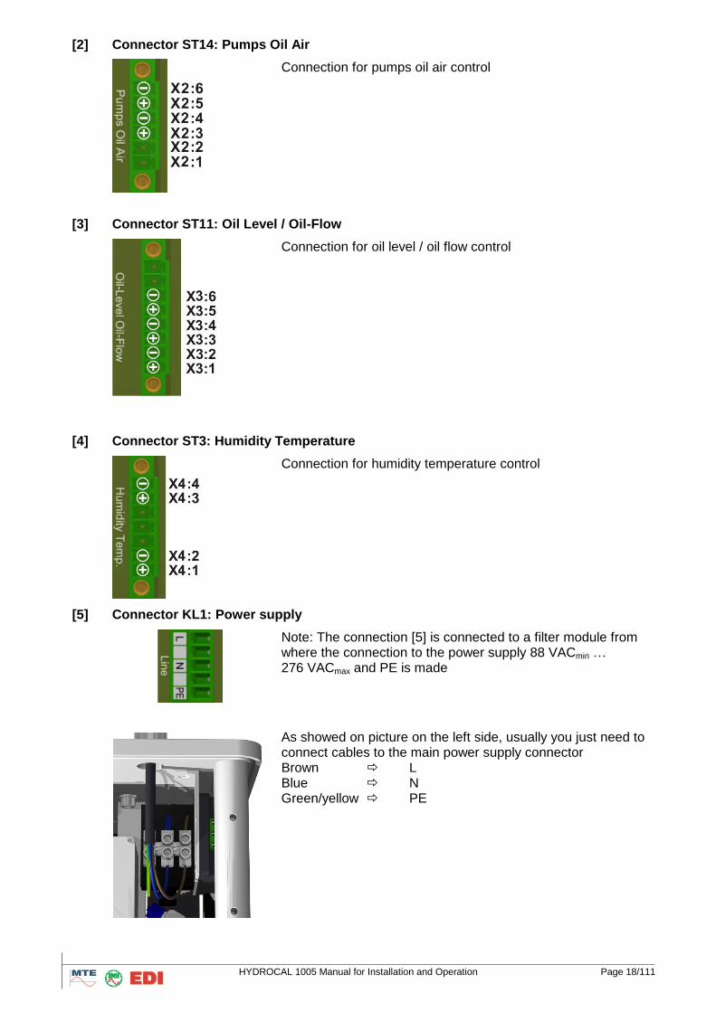
[2] Connector ST14: Pumps Oil Air
Connection for pumps oil air control
[3] Connector ST11: Oil Level / Oil-Flow
Connection for oil level / oil flow control
[4] Connector ST3: Humidity Temperature
Connection for humidity temperature control
[5] Connector KL1: Power supply
Note: The connection [5] is connected to a filter module from where the connection to the power supply 88 VACmin … 276 VACmax and PE is made
As showed on picture on the left side, usually you just need to connect cables to the main power supply connector Brown L Blue N Green/yellow PE
HYDROCAL 1005 Manual for Installation and Operation Page 19/111
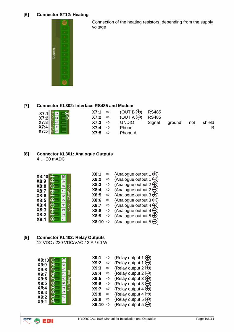
[6] Connector ST12: Heating
Connection of the heating resistors, depending from the supply voltage
[7] Connector KL302: Interface RS485 and Modem
X7:1 (OUT B ) RS485
X7:2 (OUT A ) RS485
X7:3 GNDIO Signal ground not shield
X7:4 Phone B
X7:5 Phone A
[8] Connector KL301: Analogue Outputs 4…. 20 mADC
X8:1 (Analogue output 1 )
X8:2 (Analogue output 1 )
X8:3 (Analogue output 2 )
X8:4 (Analogue output 2 )
X8:5 (Analogue output 3 )
X8:6 (Analogue output 3 )
X8:7 (Analogue output 4 )
X8:8 (Analogue output 4 )
X8:9 (Analogue output 5 )
X8:10 (Analogue output 5 )
[9] Connector KL402: Relay Outputs 12 VDC / 220 VDC/VAC / 2 A / 60 W
X9:1 (Relay output 1 )
X9:2 (Relay output 1 )
X9:3 (Relay output 2 )
X9:4 (Relay output 2 )
X9:5 (Relay output 3 )
X9:6 (Relay output 3 )
X9:7 (Relay output 4 )
X9:8 (Relay output 4 )
X9:9 (Relay output 5 )
X9:10 (Relay output 5 )
HYDROCAL 1005 Manual for Installation and Operation Page 20/111
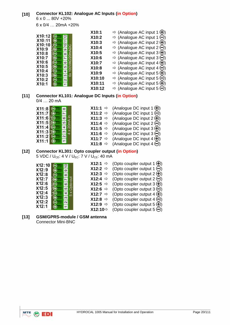
[10] Connector KL102: Analogue AC Inputs (in Option) 6 x 0 ... 80V +20%
6 x 0/4 … 20mA +20%
X10:1 (Analogue AC input 1 )
X10:2 (Analogue AC input 1 )
X10:3 (Analogue AC input 2 )
X10:4 (Analogue AC input 2 )
X10:5 (Analogue AC input 3 )
X10:6 (Analogue AC input 3 )
X10:7 (Analogue AC input 4 )
X10:8 (Analogue AC input 4 )
X10:9 (Analogue AC input 5 )
X10:10 (Analogue AC input 5 )
X10:11 (Analogue AC input 5 )
X10:12 (Analogue AC input 5 )
[11] Connector KL101: Analogue DC Inputs (in Option) 0/4 … 20 mA
X11:1 (Analogue DC input 1 )
X11:2 (Analogue DC input 1 )
X11:3 (Analogue DC input 2 )
X11:4 (Analogue DC input 2 )
X11:5 (Analogue DC input 3 )
X11:6 (Analogue DC input 3 )
X11:7 (Analogue DC input 4 )
X11:8 (Analogue DC input 4 )
[12] Connector KL301: Opto coupler output (in Option) 5 VDC / UCE: 4 V / UEC: 7 V / UCE: 40 mA
X12:1 (Opto coupler output 1 )
X12:2 (Opto coupler output 1 )
X12:3 (Opto coupler output 2 )
X12:4 (Opto coupler output 2 )
X12:5 (Opto coupler output 3 )
X12:6 (Opto coupler output 3 )
X12:7 (Opto coupler output 4 )
X12:8 (Opto coupler output 4 )
X12:9 (Opto coupler output 5 )
X12:10 (Opto coupler output 5 )
[13] GSM/GPRS-module / GSM antenna Connector Mini-BNC
HYDROCAL 1005 Manual for Installation and Operation Page 21/111
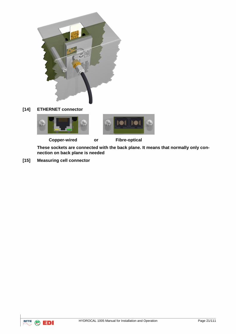
[14] ETHERNET connector
Copper-wired or Fibre-optical
These sockets are connected with the back plane. It means that normally only con-
nection on back plane is needed
[15] Measuring cell connector
HYDROCAL 1005 Manual for Installation and Operation Page 22/111
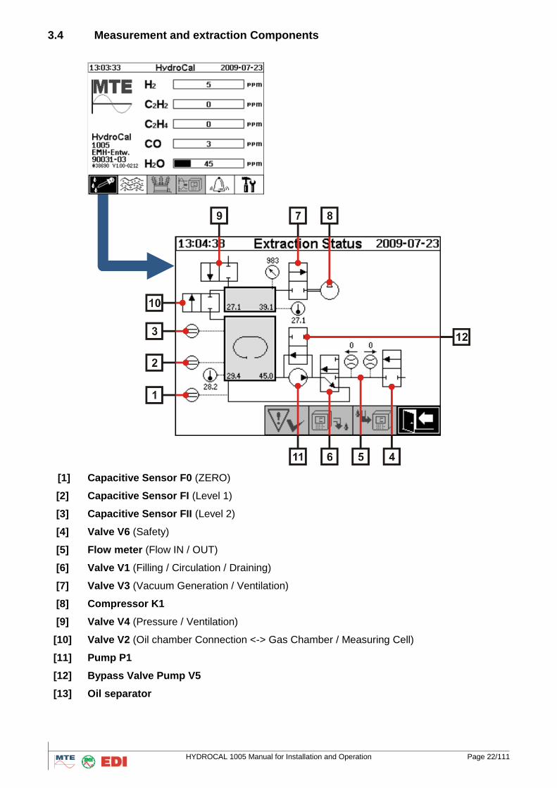
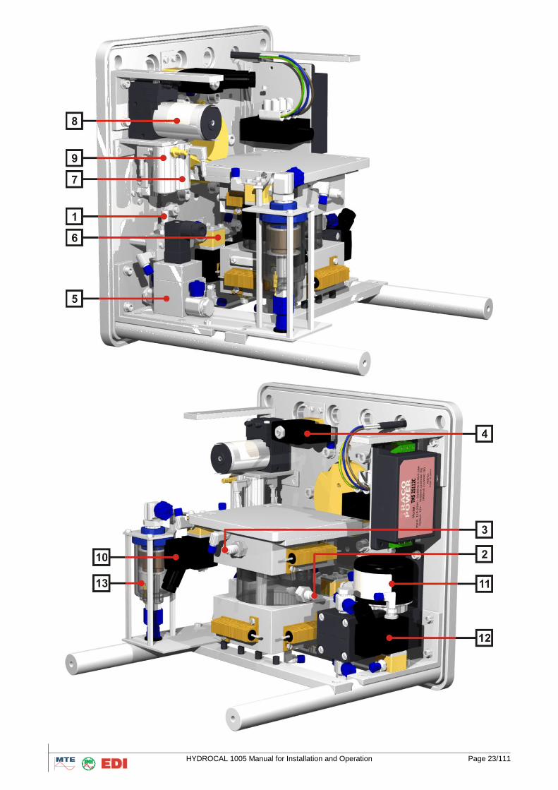
3.4 Measurement and extraction Components
[1] Capacitive Sensor F0 (ZERO)
[2] Capacitive Sensor FI (Level 1)
[3] Capacitive Sensor FII (Level 2)
[4] Valve V6 (Safety)
[5] Flow meter (Flow IN / OUT)
[6] Valve V1 (Filling / Circulation / Draining)
[7] Valve V3 (Vacuum Generation / Ventilation)
[8] Compressor K1
[9] Valve V4 (Pressure / Ventilation)
[10] Valve V2 (Oil chamber Connection <-> Gas Chamber / Measuring Cell)
[11] Pump P1
[12] Bypass Valve Pump V5
[13] Oil separator
HYDROCAL 1005 Manual for Installation and Operation Page 23/111
HYDROCAL 1005 Manual for Installation and Operation Page 24/111
4. Software on HYDROCAL unit
4.1 General information
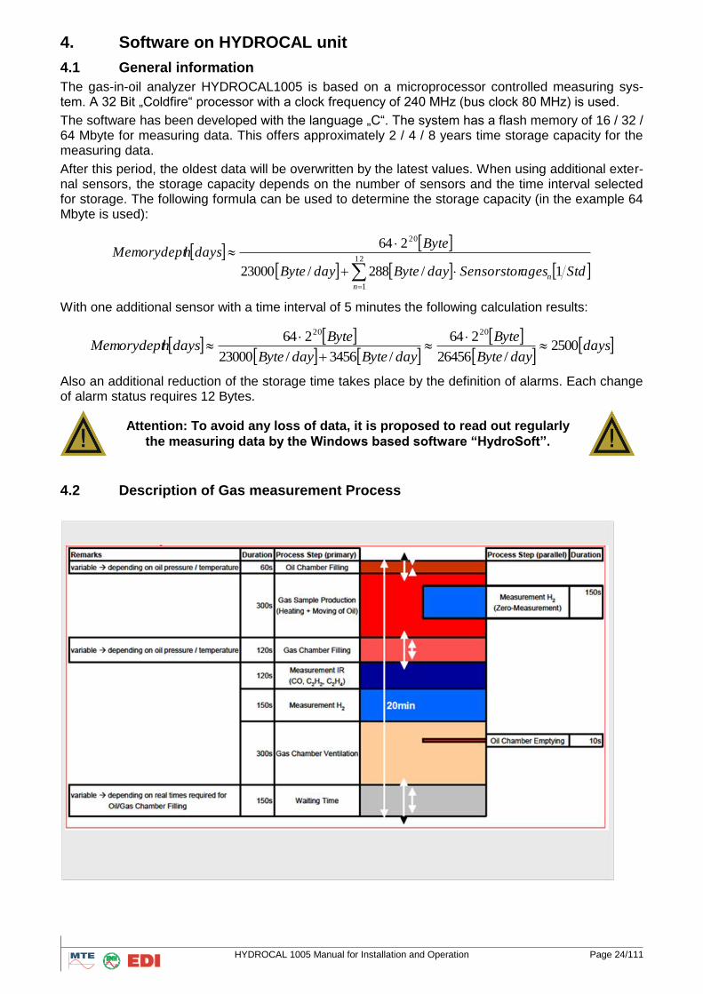
The gas-in-oil analyzer HYDROCAL1005 is based on a microprocessor controlled measuring sys-tem. A 32 Bit „Coldfire“ processor with a clock frequency of 240 MHz (bus clock 80 MHz) is used.
The software has been developed with the language „C“. The system has a flash memory of 16 / 32 / 64 Mbyte for measuring data. This offers approximately 2 / 4 / 8 years time storage capacity for the measuring data.
After this period, the oldest data will be overwritten by the latest values. When using additional exter-nal sensors, the storage capacity depends on the number of sensors and the time interval selected for storage. The following formula can be used to determine the storage capacity (in the example 64 Mbyte is used):
12
1
20
1/288/23000
264
n
n StdagesSensorstordayBytedayByte
BytedayshMemorydept
With one additional sensor with a time interval of 5 minutes the following calculation results:
days
dayByte
Byte
dayBytedayByte
BytedayshMemorydept 2500
/26456
264
/3456/23000
264 2020
Also an additional reduction of the storage time takes place by the definition of alarms. Each change of alarm status requires 12 Bytes.
Attention: To avoid any loss of data, it is proposed to read out regularly
the measuring data by the Windows based software “HydroSoft”.
4.2 Description of Gas measurement Process
HYDROCAL 1005 Manual for Installation and Operation Page 25/111
4.3. Operation Cycles
This chapter describes each process steps and provides information in regards to the safety functions as well as how to reset errors. The consequence of all errors is that the cycle will be interrupted immediately and all valves will be closed.
For all observed errors, you can acknowledged them by pressing button ..
If nothing changes, check status of all components according to actual cycle.
Check that all tubes go straight into the FESTO quick screws and any oil/air leakages have appeared
Check that cables and all pins of the plug go straight into their socket; pushing the plug in carefully.
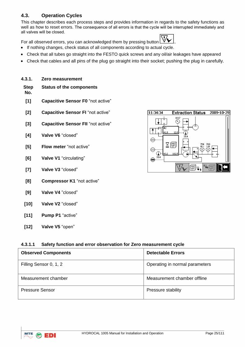
4.3.1. Zero measurement
Step
No.
Status of the components
[1] Capacitive Sensor F0 “not active”
[2] Capacitive Sensor FI “not active”
[3] Capacitive Sensor FII “not active”
[4] Valve V6 “closed”
[5] Flow meter “not active”
[6] Valve V1 “circulating”
[7] Valve V3 “closed”
[8] Compressor K1 “not active”
[9] Valve V4 ”closed”
[10] Valve V2 “closed”
[11] Pump P1 “active”
[12] Valve V5 “open”
4.3.1.1 Safety function and error observation for Zero measurement cycle
Observed Components Detectable Errors
Filling Sensor 0, 1, 2 Operating in normal parameters
Measurement chamber Measurement chamber offline
Pressure Sensor Pressure stability
HYDROCAL 1005 Manual for Installation and Operation Page 26/111
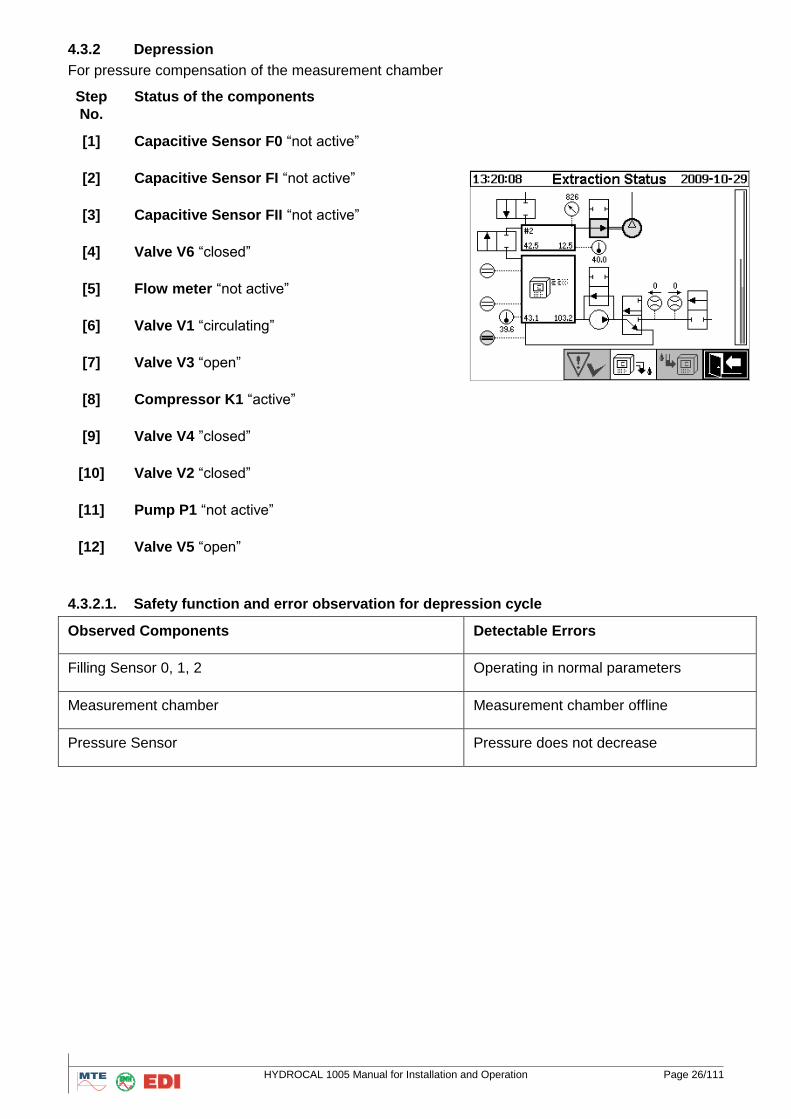
4.3.2 Depression
For pressure compensation of the measurement chamber
Step
No.
Status of the components
[1] Capacitive Sensor F0 “not active”
[2] Capacitive Sensor FI “not active”
[3] Capacitive Sensor FII “not active”
[4] Valve V6 “closed”
[5] Flow meter “not active”
[6] Valve V1 “circulating”
[7] Valve V3 “open”
[8] Compressor K1 “active”
[9] Valve V4 ”closed”
[10] Valve V2 “closed”
[11] Pump P1 “not active”
[12] Valve V5 “open”
4.3.2.1. Safety function and error observation for depression cycle
Observed Components Detectable Errors
Filling Sensor 0, 1, 2 Operating in normal parameters
Measurement chamber Measurement chamber offline
Pressure Sensor Pressure does not decrease
HYDROCAL 1005 Manual for Installation and Operation Page 27/111
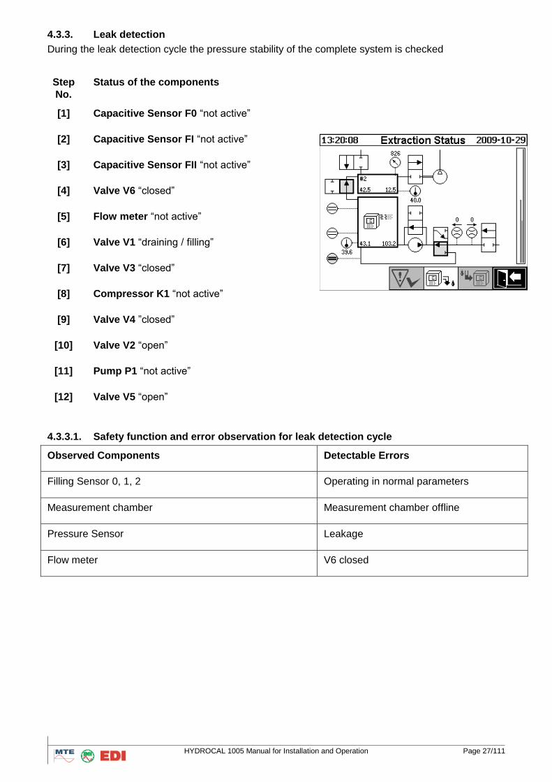
4.3.3. Leak detection
During the leak detection cycle the pressure stability of the complete system is checked
Step
No.
Status of the components
[1] Capacitive Sensor F0 “not active”
[2] Capacitive Sensor FI “not active”
[3] Capacitive Sensor FII “not active”
[4] Valve V6 “closed”
[5] Flow meter “not active”
[6] Valve V1 “draining / filling”
[7] Valve V3 “closed”
[8] Compressor K1 “not active”
[9] Valve V4 ”closed”
[10] Valve V2 “open”
[11] Pump P1 “not active”
[12] Valve V5 “open”
4.3.3.1. Safety function and error observation for leak detection cycle
Observed Components Detectable Errors
Filling Sensor 0, 1, 2 Operating in normal parameters
Measurement chamber Measurement chamber offline
Pressure Sensor Leakage
Flow meter V6 closed
HYDROCAL 1005 Manual for Installation and Operation Page 28/111
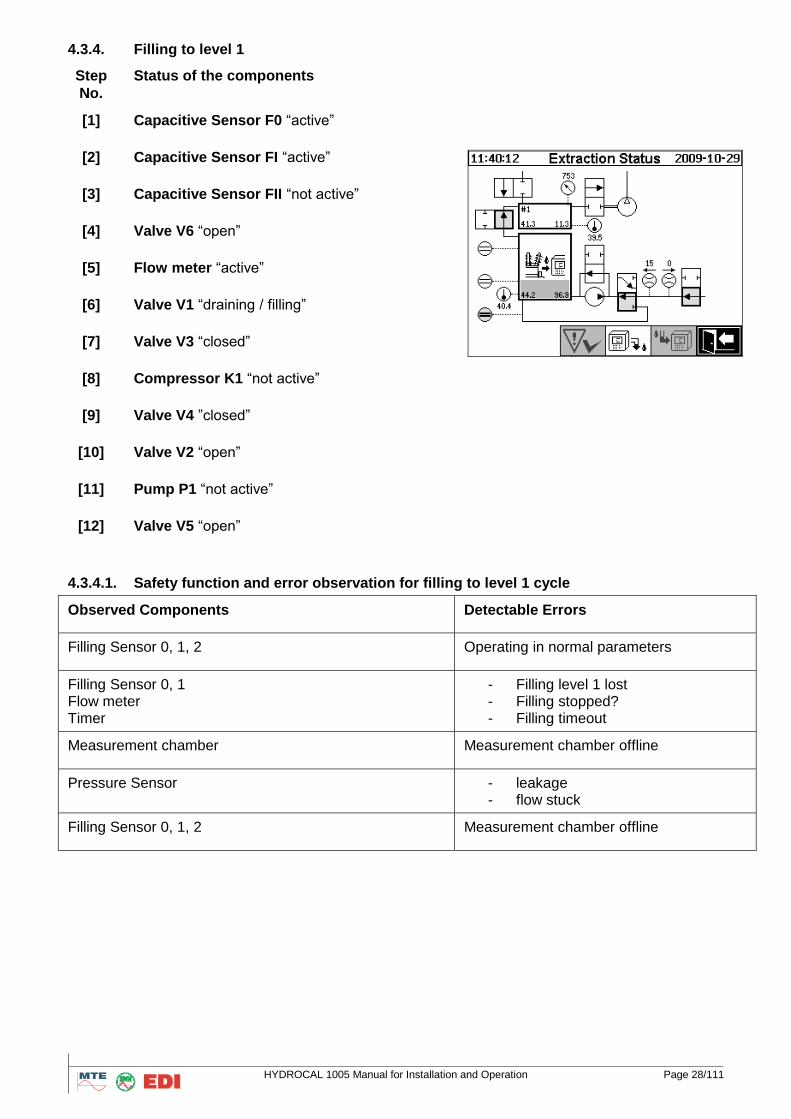
4.3.4. Filling to level 1
Step
No.
Status of the components
[1] Capacitive Sensor F0 “active”
[2] Capacitive Sensor FI “active”
[3] Capacitive Sensor FII “not active”
[4] Valve V6 “open”
[5] Flow meter “active”
[6] Valve V1 “draining / filling”
[7] Valve V3 “closed”
[8] Compressor K1 “not active”
[9] Valve V4 ”closed”
[10] Valve V2 “open”
[11] Pump P1 “not active”
[12] Valve V5 “open”
4.3.4.1. Safety function and error observation for filling to level 1 cycle
Observed Components Detectable Errors
Filling Sensor 0, 1, 2 Operating in normal parameters
Filling Sensor 0, 1 Flow meter Timer
- Filling level 1 lost - Filling stopped? - Filling timeout
Measurement chamber Measurement chamber offline
Pressure Sensor - leakage - flow stuck
Filling Sensor 0, 1, 2 Measurement chamber offline
HYDROCAL 1005 Manual for Installation and Operation Page 29/111
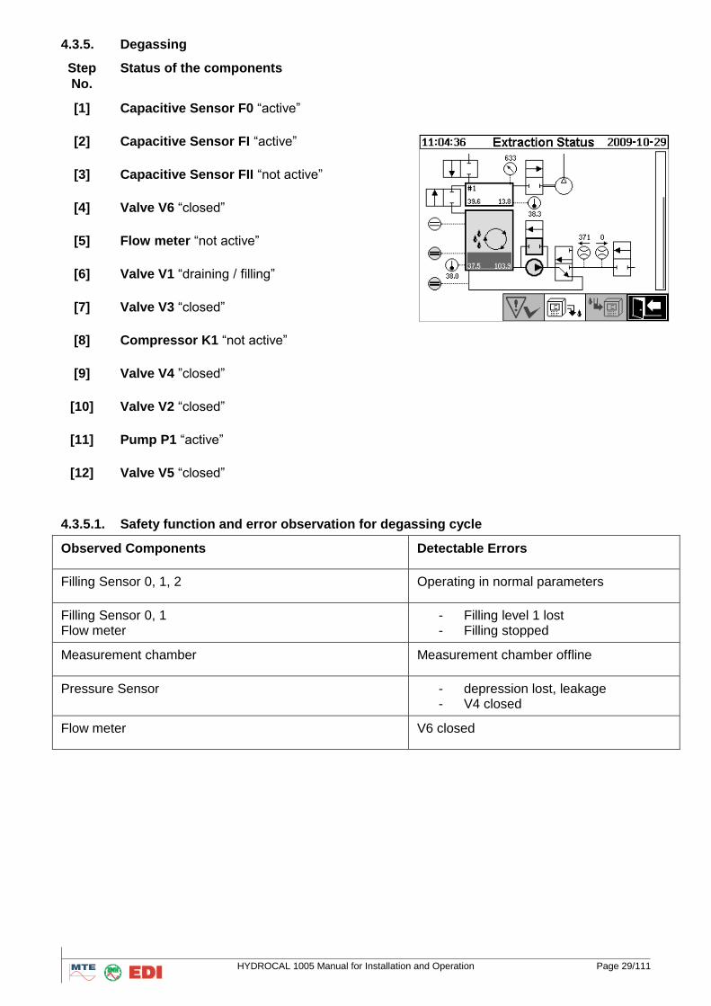
4.3.5. Degassing
Step
No.
Status of the components
[1] Capacitive Sensor F0 “active”
[2] Capacitive Sensor FI “active”
[3] Capacitive Sensor FII “not active”
[4] Valve V6 “closed”
[5] Flow meter “not active”
[6] Valve V1 “draining / filling”
[7] Valve V3 “closed”
[8] Compressor K1 “not active”
[9] Valve V4 ”closed”
[10] Valve V2 “closed”
[11] Pump P1 “active”
[12] Valve V5 “closed”
4.3.5.1. Safety function and error observation for degassing cycle
Observed Components Detectable Errors
Filling Sensor 0, 1, 2 Operating in normal parameters
Filling Sensor 0, 1 Flow meter
- Filling level 1 lost - Filling stopped
Measurement chamber Measurement chamber offline
Pressure Sensor - depression lost, leakage - V4 closed
Flow meter V6 closed
HYDROCAL 1005 Manual for Installation and Operation Page 30/111
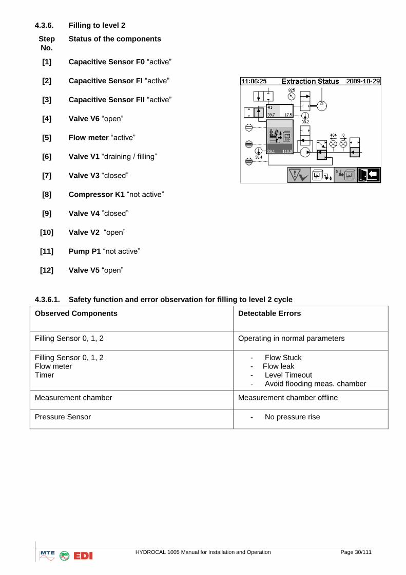
4.3.6. Filling to level 2
Step
No.
Status of the components
[1] Capacitive Sensor F0 “active”
[2] Capacitive Sensor FI “active”
[3] Capacitive Sensor FII “active”
[4] Valve V6 “open”
[5] Flow meter “active”
[6] Valve V1 “draining / filling”
[7] Valve V3 “closed”
[8] Compressor K1 “not active”
[9] Valve V4 ”closed”
[10] Valve V2 “open”
[11] Pump P1 “not active”
[12] Valve V5 “open”
4.3.6.1. Safety function and error observation for filling to level 2 cycle
Observed Components Detectable Errors
Filling Sensor 0, 1, 2 Operating in normal parameters
Filling Sensor 0, 1, 2 Flow meter Timer
- Flow Stuck - Flow leak - Level Timeout - Avoid flooding meas. chamber
Measurement chamber Measurement chamber offline
Pressure Sensor - No pressure rise
HYDROCAL 1005 Manual for Installation and Operation Page 31/111
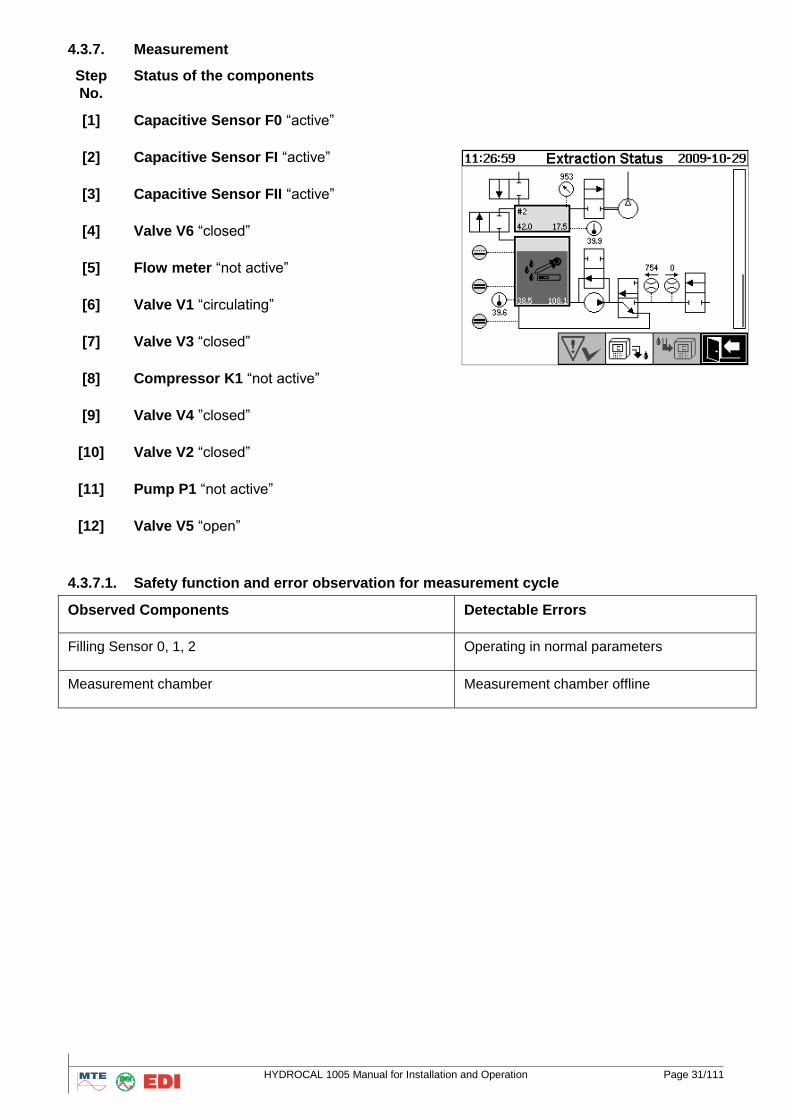
4.3.7. Measurement
Step
No.
Status of the components
[1] Capacitive Sensor F0 “active”
[2] Capacitive Sensor FI “active”
[3] Capacitive Sensor FII “active”
[4] Valve V6 “closed”
[5] Flow meter “not active”
[6] Valve V1 “circulating”
[7] Valve V3 “closed”
[8] Compressor K1 “not active”
[9] Valve V4 ”closed”
[10] Valve V2 “closed”
[11] Pump P1 “not active”
[12] Valve V5 “open”
4.3.7.1. Safety function and error observation for measurement cycle
Observed Components Detectable Errors
Filling Sensor 0, 1, 2 Operating in normal parameters
Measurement chamber Measurement chamber offline
HYDROCAL 1005 Manual for Installation and Operation Page 32/111
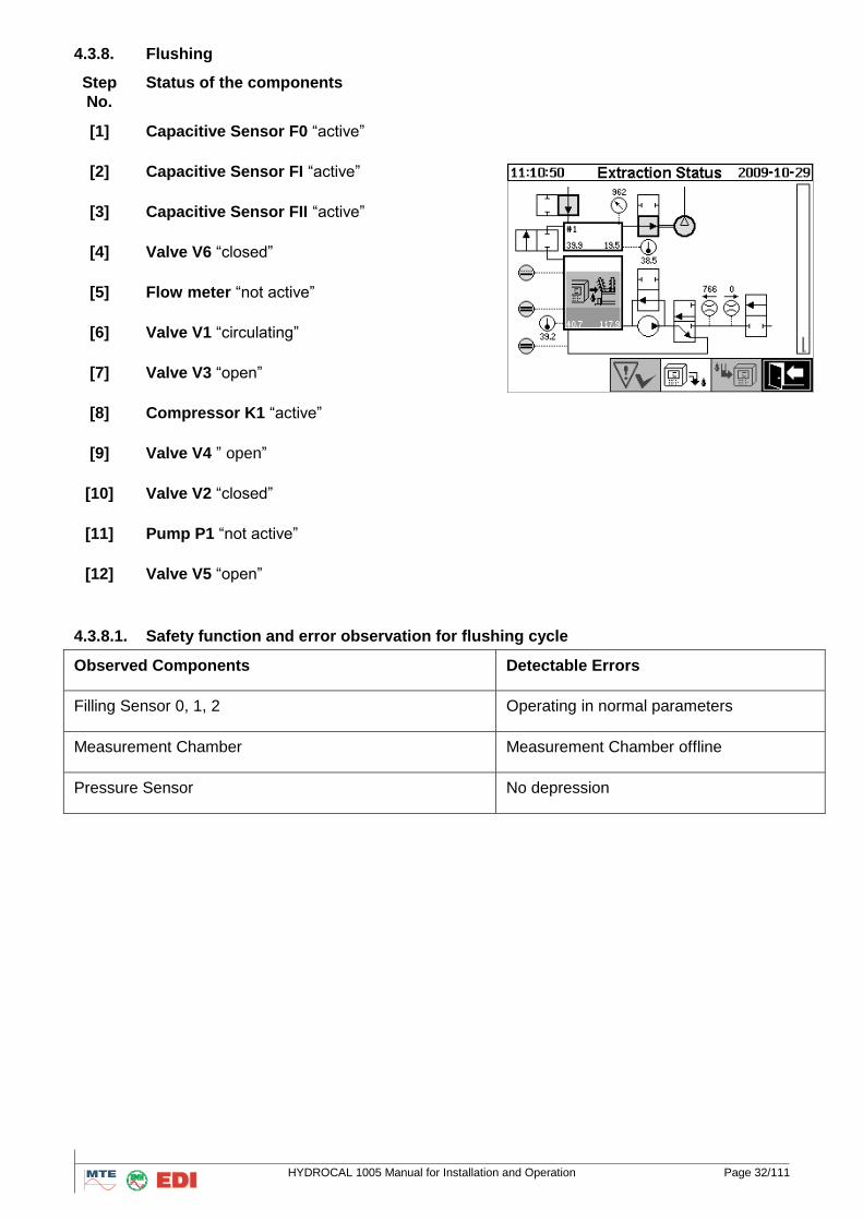
4.3.8. Flushing
Step
No.
Status of the components
[1] Capacitive Sensor F0 “active”
[2] Capacitive Sensor FI “active”
[3] Capacitive Sensor FII “active”
[4] Valve V6 “closed”
[5] Flow meter “not active”
[6] Valve V1 “circulating”
[7] Valve V3 “open”
[8] Compressor K1 “active”
[9] Valve V4 ” open”
[10] Valve V2 “closed”
[11] Pump P1 “not active”
[12] Valve V5 “open”
4.3.8.1. Safety function and error observation for flushing cycle
Observed Components Detectable Errors
Filling Sensor 0, 1, 2 Operating in normal parameters
Measurement Chamber Measurement Chamber offline
Pressure Sensor No depression
HYDROCAL 1005 Manual for Installation and Operation Page 33/111
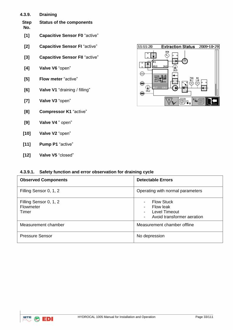
4.3.9. Draining
Step
No.
Status of the components
[1] Capacitive Sensor F0 “active”
[2] Capacitive Sensor FI “active”
[3] Capacitive Sensor FII “active”
[4] Valve V6 “open”
[5] Flow meter “active”
[6] Valve V1 “draining / filling”
[7] Valve V3 “open”
[8] Compressor K1 “active”
[9] Valve V4 ” open”
[10] Valve V2 “open”
[11] Pump P1 “active”
[12] Valve V5 “closed”
4.3.9.1. Safety function and error observation for draining cycle
Observed Components Detectable Errors
Filling Sensor 0, 1, 2 Operating with normal parameters
Filling Sensor 0, 1, 2 Flowmeter Timer
- Flow Stuck - Flow leak - Level Timeout - Avoid transformer aeration
Measurement chamber Measurement chamber offline
Pressure Sensor No depression
HYDROCAL 1005 Manual for Installation and Operation Page 34/111
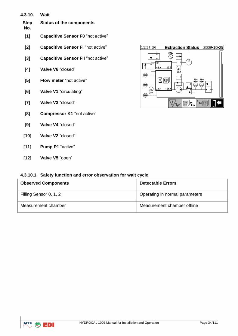
4.3.10. Wait
Step
No.
Status of the components
[1] Capacitive Sensor F0 “not active”
[2] Capacitive Sensor FI “not active”
[3] Capacitive Sensor FII “not active”
[4] Valve V6 “closed”
[5] Flow meter “not active”
[6] Valve V1 “circulating”
[7] Valve V3 “closed”
[8] Compressor K1 “not active”
[9] Valve V4 ”closed”
[10] Valve V2 “closed”
[11] Pump P1 “active”
[12] Valve V5 “open”
4.3.10.1. Safety function and error observation for wait cycle
Observed Components Detectable Errors
Filling Sensor 0, 1, 2 Operating in normal parameters
Measurement chamber Measurement chamber offline
HYDROCAL 1005 Manual for Installation and Operation Page 35/111
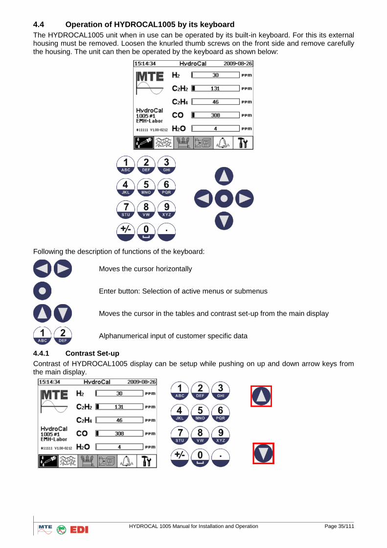
4.4 Operation of HYDROCAL1005 by its keyboard
The HYDROCAL1005 unit when in use can be operated by its built-in keyboard. For this its external housing must be removed. Loosen the knurled thumb screws on the front side and remove carefully the housing. The unit can then be operated by the keyboard as shown below:
Following the description of functions of the keyboard:
Moves the cursor horizontally
Enter button: Selection of active menus or submenus
Moves the cursor in the tables and contrast set-up from the main display
Alphanumerical input of customer specific data
4.4.1 Contrast Set-up
Contrast of HYDROCAL1005 display can be setup while pushing on up and down arrow keys from the main display.
HYDROCAL 1005 Manual for Installation and Operation Page 36/111
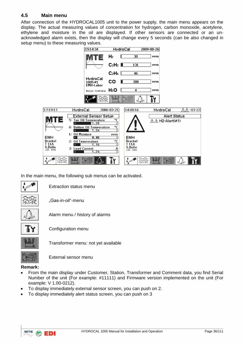
4.5 Main menu
After connection of the HYDROCAL1005 unit to the power supply, the main menu appears on the display. The actual measuring values of concentration for hydrogen, carbon monoxide, acetylene, ethylene and moisture in the oil are displayed. If other sensors are connected or an un-acknowledged alarm exists, then the display will change every 5 seconds (can be also changed in setup menu) to these measuring values.
In the main menu, the following sub menus can be activated.
Extraction status menu
„Gas-in-oil“-menu
Alarm menu / history of alarms
Configuration menu
Transformer menu: not yet available
External sensor menu
Remark:
From the main display under Customer, Station, Transformer and Comment data, you find Serial Number of the unit (For example: #11111) and Firmware version implemented on the unit (For example: V 1.00-0212).
To display immediately external sensor screen, you can push on 2.
To display immediately alert status screen, you can push on 3
HYDROCAL 1005 Manual for Installation and Operation Page 37/111
4.6 Extraction Menu
Please refer chapter 2.6.”Installation completion”
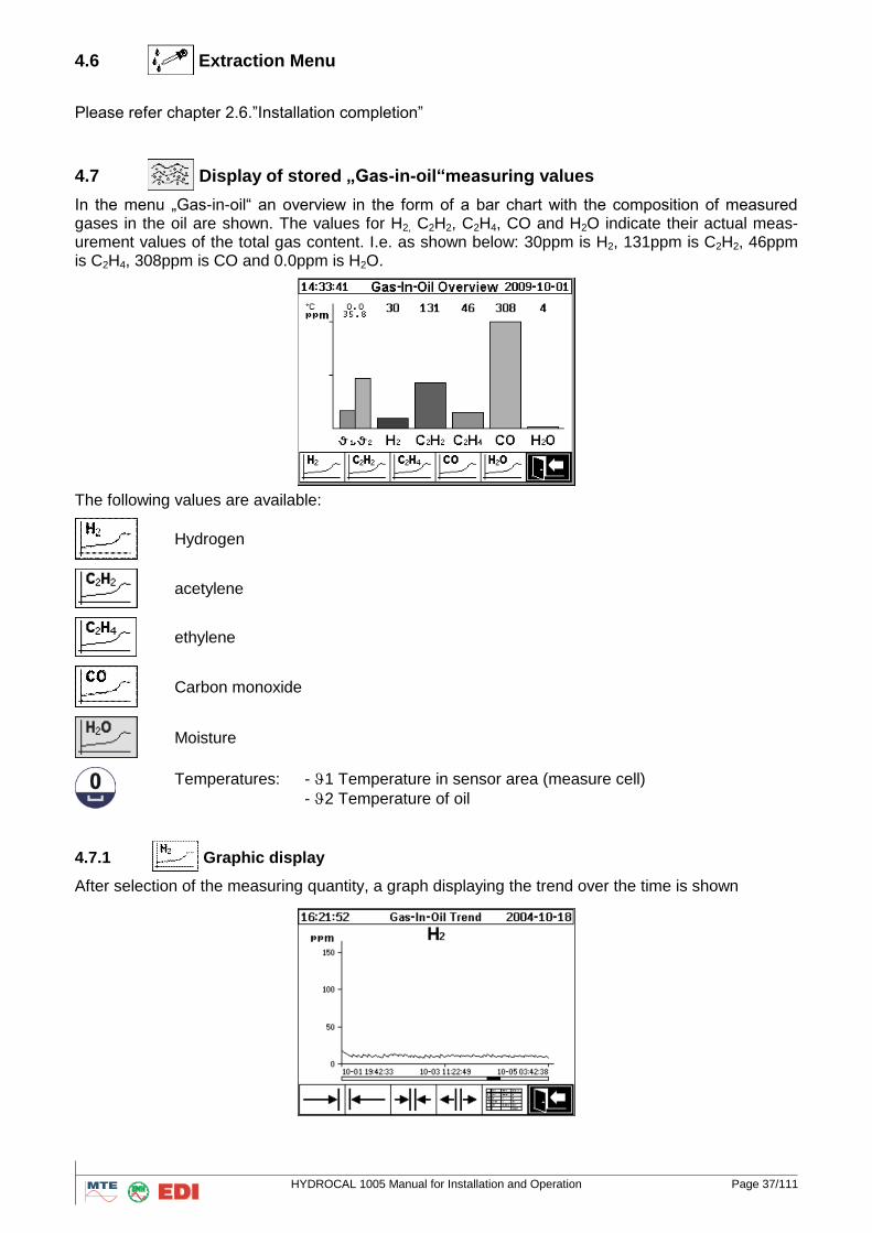
4.7 Display of stored „Gas-in-oil“measuring values
In the menu „Gas-in-oil“ an overview in the form of a bar chart with the composition of measured gases in the oil are shown. The values for H2, C2H2, C2H4, CO and H2O indicate their actual meas-urement values of the total gas content. I.e. as shown below: 30ppm is H2, 131ppm is C2H2, 46ppm is C2H4, 308ppm is CO and 0.0ppm is H2O.
The following values are available:
Hydrogen
acetylene
ethylene
Carbon monoxide
Moisture
Temperatures: - 1 Temperature in sensor area (measure cell)
- 2 Temperature of oil
4.7.1
Graphic display
After selection of the measuring quantity, a graph displaying the trend over the time is shown
HYDROCAL 1005 Manual for Installation and Operation Page 38/111
Following functions are available:
Scroll graph to the right
Scroll graph to the left
Zoom-out with minimum resolution of 3 days / page
Zoom-in with maximum resolution of 8 hours / page
Go to table presentation
Exit
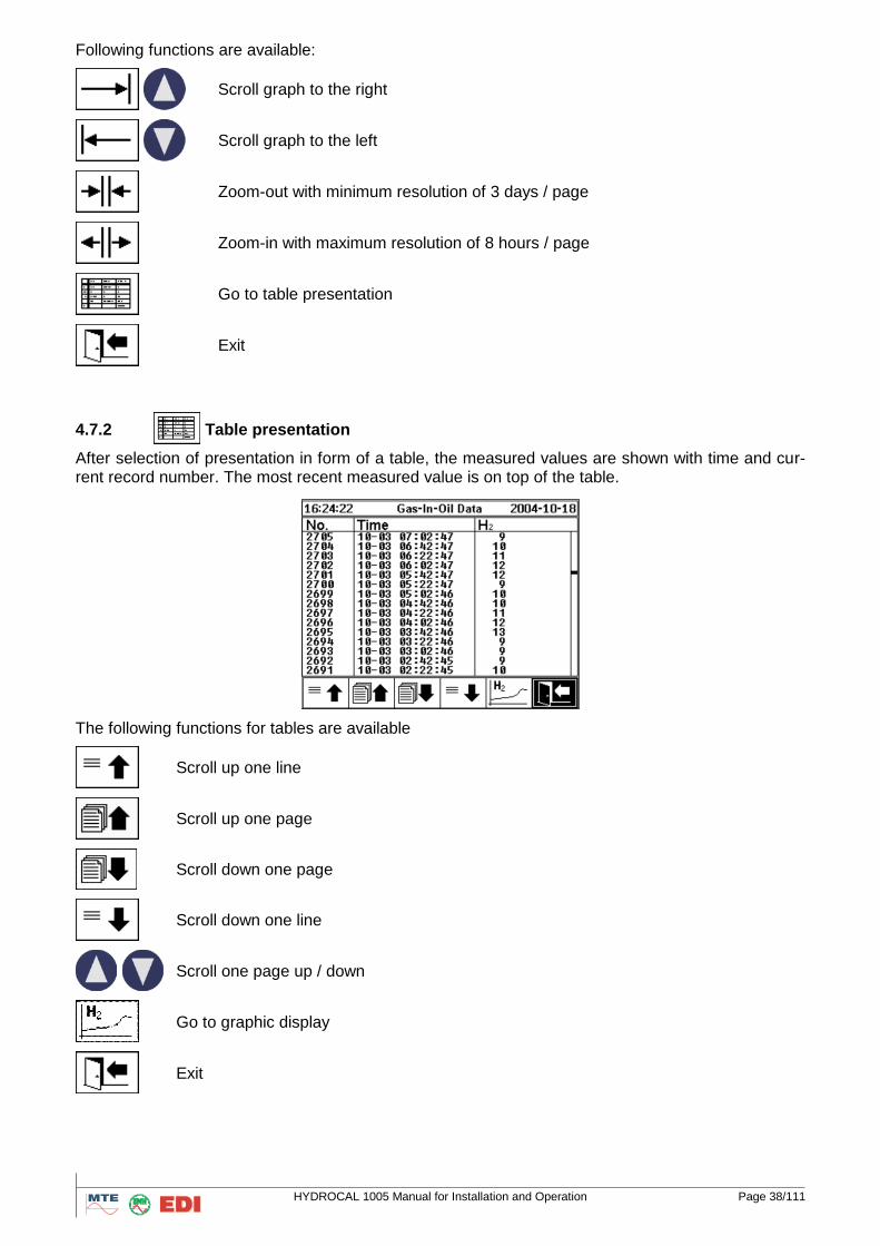
4.7.2
Table presentation
After selection of presentation in form of a table, the measured values are shown with time and cur-rent record number. The most recent measured value is on top of the table.
The following functions for tables are available
Scroll up one line
Scroll up one page
Scroll down one page
Scroll down one line
Scroll one page up / down
Go to graphic display
Exit
HYDROCAL 1005 Manual for Installation and Operation Page 39/111
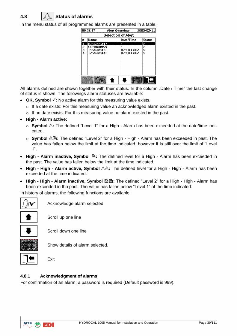
4.8 Status of alarms
In the menu status of all programmed alarms are presented in a table.
All alarms defined are shown together with their status. In the column „Date / Time” the last change of status is shown. The followings alarm statuses are available:
OK, Symbol : No active alarm for this measuring value exists.
o If a date exists: For this measuring value an acknowledged alarm existed in the past.
o If no date exists: For this measuring value no alarm existed in the past.
High - Alarm active:
o Symbol : The defined “Level 1“ for a High - Alarm has been exceeded at the date/time indi-cated.
o Symbol : The defined “Level 2“ for a High - High - Alarm has been exceeded in past. The
value has fallen below the limit at the time indicated, however it is still over the limit of “Level 1“.
High - Alarm inactive, Symbol : The defined level for a High - Alarm has been exceeded in
the past. The value has fallen below the limit at the time indicated.
High - High - Alarm active, Symbol : The defined level for a High - High - Alarm has been exceeded at the time indicated.
High - High - Alarm inactive, Symbol : The defined “Level 2“ for a High - High - Alarm has
been exceeded in the past. The value has fallen below “Level 1“ at the time indicated.
In history of alarms, the following functions are available:
Acknowledge alarm selected
Scroll up one line
Scroll down one line
Show details of alarm selected.
Exit
4.8.1 Acknowledgment of alarms
For confirmation of an alarm, a password is required (Default password is 999).
HYDROCAL 1005 Manual for Installation and Operation Page 40/111
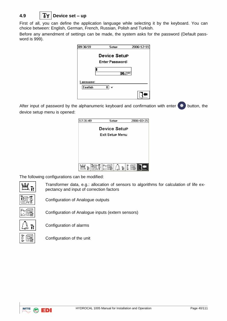
4.9 Device set – up
First of all, you can define the application language while selecting it by the keyboard. You can choice between: English, German, French, Russian, Polish and Turkish.
Before any amendment of settings can be made, the system asks for the password (Default pass-word is 999).
After input of password by the alphanumeric keyboard and confirmation with enter button, the
device setup menu is opened:
The following configurations can be modified:
Transformer data, e.g.: allocation of sensors to algorithms for calculation of life ex-pectancy and input of correction factors
Configuration of Analogue outputs
Configuration of Analogue inputs (extern sensors)
Configuration of alarms
Configuration of the unit
HYDROCAL 1005 Manual for Installation and Operation Page 41/111
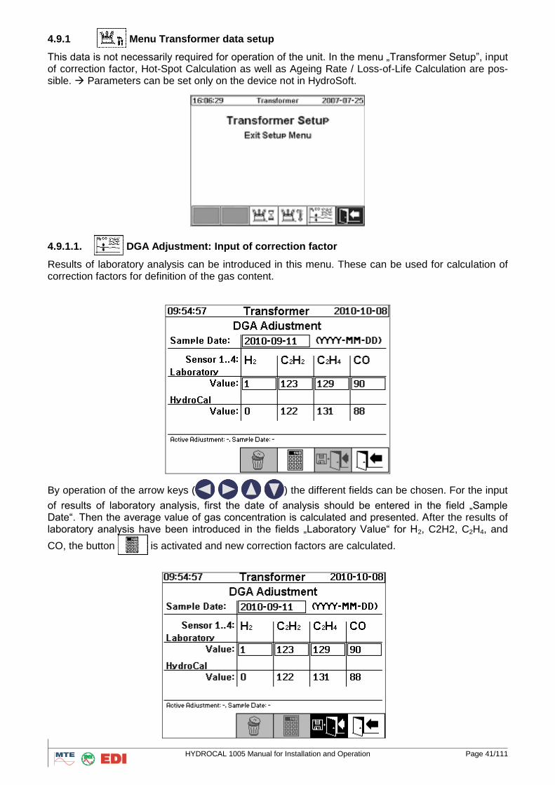
4.9.1
Menu Transformer data setup
This data is not necessarily required for operation of the unit. In the menu „Transformer Setup”, input of correction factor, Hot-Spot Calculation as well as Ageing Rate / Loss-of-Life Calculation are pos-sible. Parameters can be set only on the device not in HydroSoft.
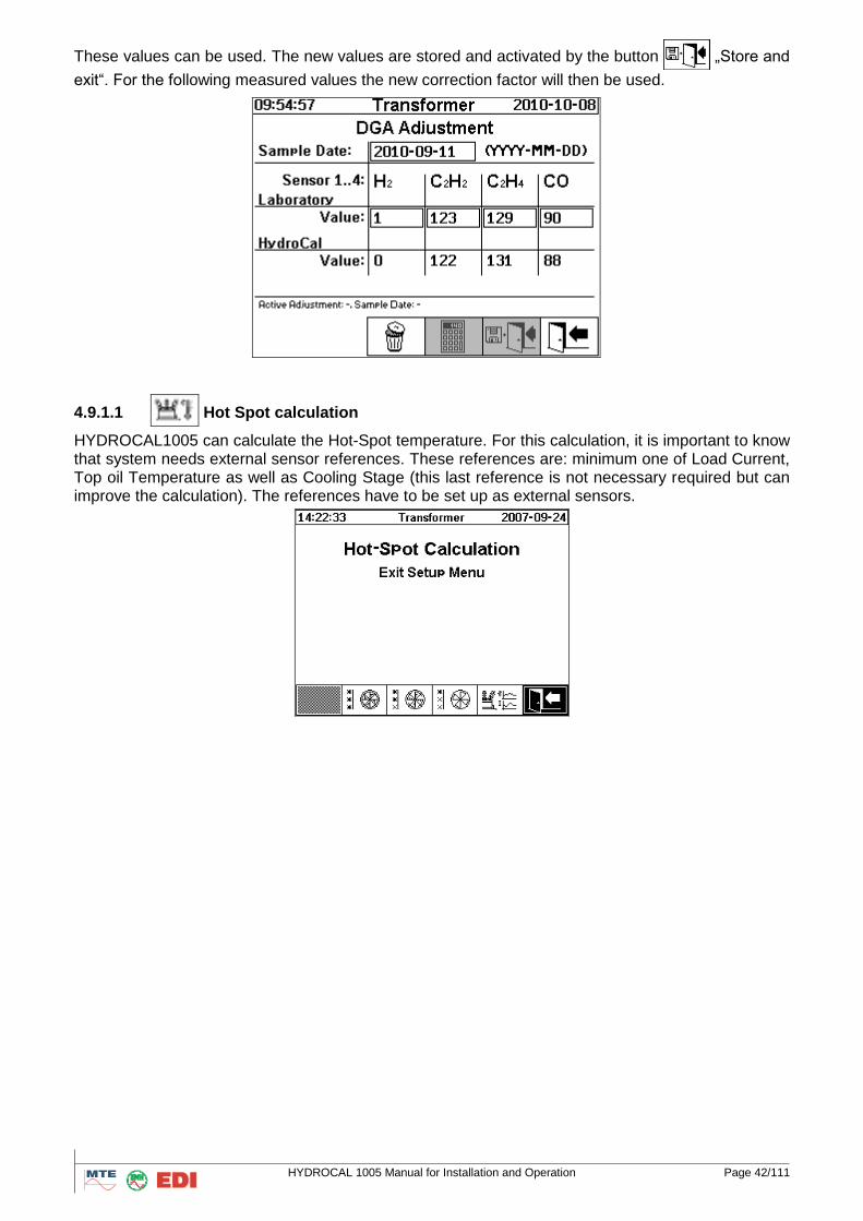
4.9.1.1. DGA Adjustment: Input of correction factor
Results of laboratory analysis can be introduced in this menu. These can be used for calculation of correction factors for definition of the gas content.
By operation of the arrow keys (
) the different fields can be chosen. For the input
of results of laboratory analysis, first the date of analysis should be entered in the field „Sample Date“. Then the average value of gas concentration is calculated and presented. After the results of laboratory analysis have been introduced in the fields „Laboratory Value“ for H2, C2H2, C2H4, and
CO, the button is activated and new correction factors are calculated.
HYDROCAL 1005 Manual for Installation and Operation Page 42/111
These values can be used. The new values are stored and activated by the button „Store and
exit“. For the following measured values the new correction factor will then be used.
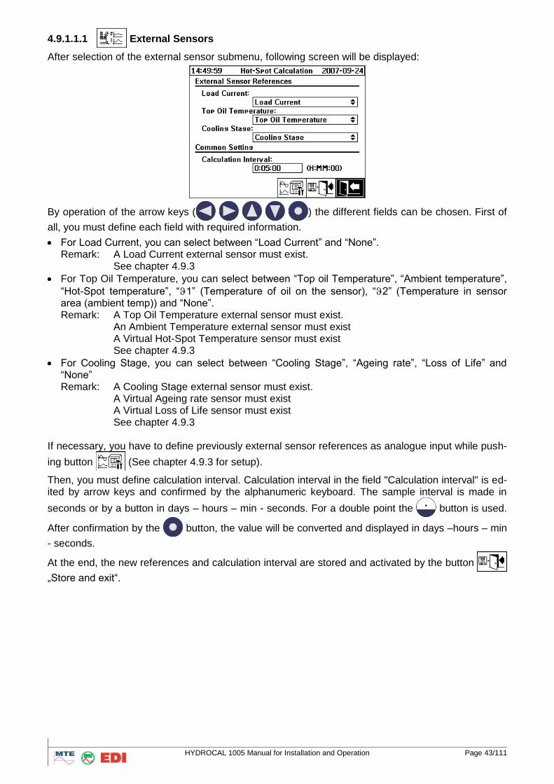
4.9.1.1 Hot Spot calculation
HYDROCAL1005 can calculate the Hot-Spot temperature. For this calculation, it is important to know that system needs external sensor references. These references are: minimum one of Load Current, Top oil Temperature as well as Cooling Stage (this last reference is not necessary required but can improve the calculation). The references have to be set up as external sensors.
HYDROCAL 1005 Manual for Installation and Operation Page 43/111
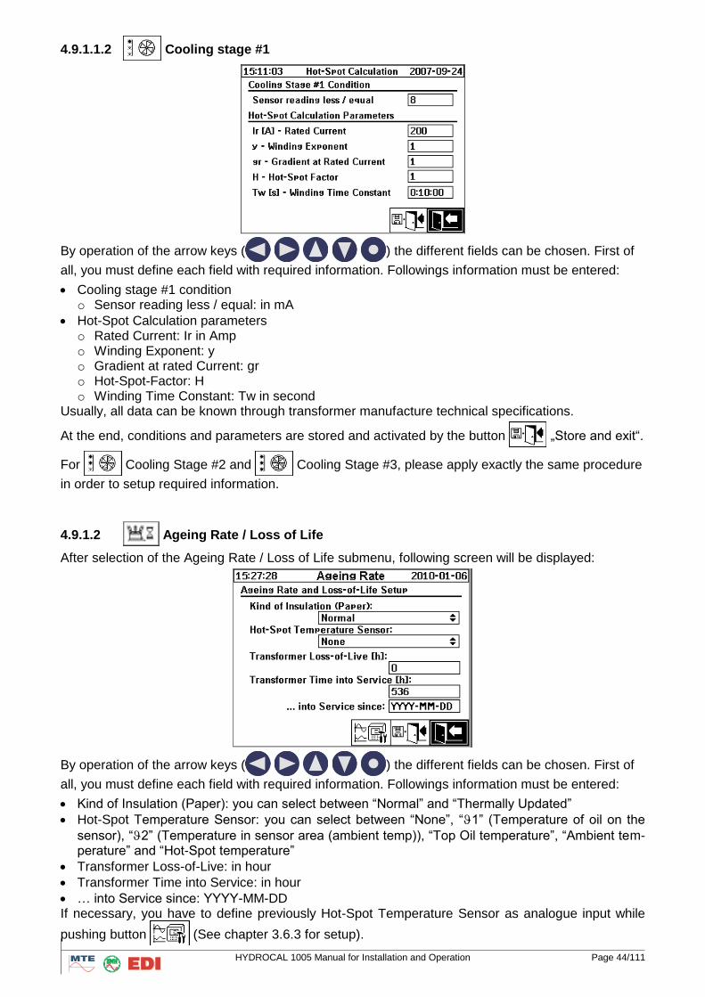
4.9.1.1.1 External Sensors
After selection of the external sensor submenu, following screen will be displayed:
By operation of the arrow keys (
) the different fields can be chosen. First of
all, you must define each field with required information.
For Load Current, you can select between “Load Current” and “None”. Remark: A Load Current external sensor must exist. See chapter 4.9.3
For Top Oil Temperature, you can select between “Top oil Temperature”, “Ambient temperature”,
“Hot-Spot temperature”, “1” (Temperature of oil on the sensor), “2” (Temperature in sensor area (ambient temp)) and “None”. Remark: A Top Oil Temperature external sensor must exist. An Ambient Temperature external sensor must exist A Virtual Hot-Spot Temperature sensor must exist See chapter 4.9.3
For Cooling Stage, you can select between “Cooling Stage”, “Ageing rate”, “Loss of Life” and “None” Remark: A Cooling Stage external sensor must exist. A Virtual Ageing rate sensor must exist A Virtual Loss of Life sensor must exist See chapter 4.9.3
If necessary, you have to define previously external sensor references as analogue input while push-
ing button (See chapter 4.9.3 for setup).
Then, you must define calculation interval. Calculation interval in the field "Calculation interval" is ed-ited by arrow keys and confirmed by the alphanumeric keyboard. The sample interval is made in
seconds or by a button in days – hours – min - seconds. For a double point the button is used.
After confirmation by the button, the value will be converted and displayed in days –hours – min
- seconds.
At the end, the new references and calculation interval are stored and activated by the button
„Store and exit“.
HYDROCAL 1005 Manual for Installation and Operation Page 44/111
4.9.1.1.2 Cooling stage #1
By operation of the arrow keys (
) the different fields can be chosen. First of
all, you must define each field with required information. Followings information must be entered:
Cooling stage #1 condition o Sensor reading less / equal: in mA
Hot-Spot Calculation parameters o Rated Current: Ir in Amp o Winding Exponent: y o Gradient at rated Current: gr o Hot-Spot-Factor: H o Winding Time Constant: Tw in second
Usually, all data can be known through transformer manufacture technical specifications.
At the end, conditions and parameters are stored and activated by the button „Store and exit“.
For Cooling Stage #2 and Cooling Stage #3, please apply exactly the same procedure
in order to setup required information.
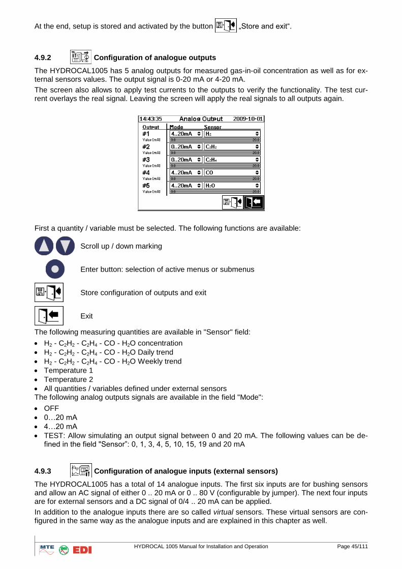
4.9.1.2 Ageing Rate / Loss of Life
After selection of the Ageing Rate / Loss of Life submenu, following screen will be displayed:
By operation of the arrow keys (
) the different fields can be chosen. First of
all, you must define each field with required information. Followings information must be entered:
Kind of Insulation (Paper): you can select between “Normal” and “Thermally Updated”
Hot-Spot Temperature Sensor: you can select between “None”, “1” (Temperature of oil on the
sensor), “2” (Temperature in sensor area (ambient temp)), “Top Oil temperature”, “Ambient tem-perature” and “Hot-Spot temperature”
Transformer Loss-of-Live: in hour
Transformer Time into Service: in hour
… into Service since: YYYY-MM-DD If necessary, you have to define previously Hot-Spot Temperature Sensor as analogue input while
pushing button (See chapter 3.6.3 for setup).
HYDROCAL 1005 Manual for Installation and Operation Page 45/111
At the end, setup is stored and activated by the button „Store and exit“.
4.9.2 Configuration of analogue outputs
The HYDROCAL1005 has 5 analog outputs for measured gas-in-oil concentration as well as for ex-ternal sensors values. The output signal is 0-20 mA or 4-20 mA.
The screen also allows to apply test currents to the outputs to verify the functionality. The test cur-rent overlays the real signal. Leaving the screen will apply the real signals to all outputs again.
First a quantity / variable must be selected. The following functions are available:
Scroll up / down marking
Enter button: selection of active menus or submenus
Store configuration of outputs and exit
Exit
The following measuring quantities are available in "Sensor" field:
H2 - C2H2 - C2H4 - CO - H2O concentration
H2 - C2H2 - C2H4 - CO - H2O Daily trend
H2 - C2H2 - C2H4 - CO - H2O Weekly trend
Temperature 1
Temperature 2
All quantities / variables defined under external sensors The following analog outputs signals are available in the field "Mode":
OFF
0…20 mA
4…20 mA
TEST: Allow simulating an output signal between 0 and 20 mA. The following values can be de-fined in the field "Sensor”: 0, 1, 3, 4, 5, 10, 15, 19 and 20 mA
4.9.3 Configuration of analogue inputs (external sensors)
The HYDROCAL1005 has a total of 14 analogue inputs. The first six inputs are for bushing sensors and allow an AC signal of either 0 .. 20 mA or 0 .. 80 V (configurable by jumper). The next four inputs are for external sensors and a DC signal of 0/4 .. 20 mA can be applied.
In addition to the analogue inputs there are so called virtual sensors. These virtual sensors are con-figured in the same way as the analogue inputs and are explained in this chapter as well.
HYDROCAL 1005 Manual for Installation and Operation Page 46/111
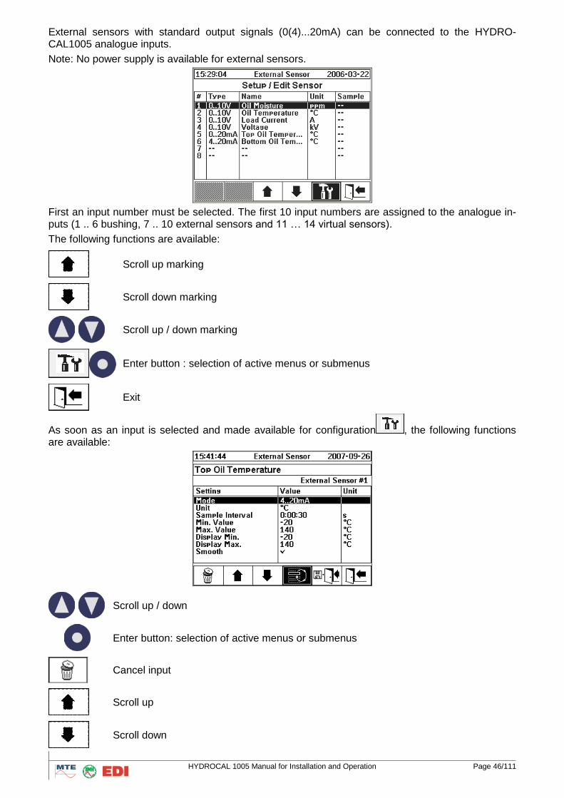
External sensors with standard output signals (0(4)...20mA) can be connected to the HYDRO-CAL1005 analogue inputs.
Note: No power supply is available for external sensors.
First an input number must be selected. The first 10 input numbers are assigned to the analogue in-puts (1 .. 6 bushing, 7 .. 10 external sensors and 11 … 14 virtual sensors).
The following functions are available:
Scroll up marking
Scroll down marking
Scroll up / down marking
Enter button : selection of active menus or submenus
Exit
As soon as an input is selected and made available for configuration , the following functions are available:
Scroll up / down
Enter button: selection of active menus or submenus
Cancel input
Scroll up
Scroll down
HYDROCAL 1005 Manual for Installation and Operation Page 47/111
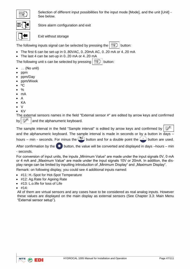
Selection of different input possibilities for the input mode [Mode], and the unit [Unit] - See below.
Store alarm configuration and exit
Exit without storage
The following inputs signal can be selected by pressing the button:
The first 6 can be set-up in 0..80VAC, 0..20mA AC, 0..20 mA or 4..20 mA
The last 4 can be set-up in 0..20 mA or 4..20 mA
The following unit s can be selected by pressing button:
… (No unit)
ppm
ppm/Day
ppm/Week
ºC
%
mA
A
KA
V
KV The external sensors names in the field "External sensor #" are edited by arrow keys and confirmed
by and the alphanumeric keyboard.
The sample interval in the field "Sample interval" is edited by arrow keys and confirmed by
and the alphanumeric keyboard. The sample interval is made in seconds or by a button in days –
hours – min - seconds. For minus the button and for a double point the button are used.
After confirmation by the button, the value will be converted and displayed in days –hours – min
- seconds.
For conversion of input units, the inputs „Minimum Value“ are made under the input signals 0V, 0 mA or 4 mA and „Maximum Value“ are made under the input signals 10V or 20mA. In addition, the dis-play range can be limited by inputting introduction of „Minimum Display“ and „Maximum Display“.
Remark: on following display, you could see 4 additional inputs named:
#11: H.-Spot for Hot-Spot Temperature
#12: Ag.Rate for Ageing Rate
#13: L.o.life for loss of Life
#14: All of them are virtual sensors and any cases have to be considered as real analog inputs. However these values are displayed on the main display as external sensors (See Chapter 3.3: Main Menu “External sensor setup”).
HYDROCAL 1005 Manual for Installation and Operation Page 48/111
4.9.4
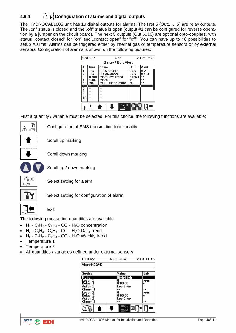
Configuration of alarms and digital outputs
The HYDROCAL1005 unit has 10 digital outputs for alarms. The first 5 (Out1 ...5) are relay outputs. The „on“ status is closed and the „off“ status is open (output #1 can be configured for reverse opera-tion by a jumper on the circuit board). The next 5 outputs (Out 6..10) are optional opto-couplers, with status „contact closed“ for “on“ and „contact open“ for “off“. You can have up to 16 possibilities to setup Alarms. Alarms can be triggered either by internal gas or temperature sensors or by external sensors. Configuration of alarms is shown on the following pictures:
First a quantity / variable must be selected. For this choice, the following functions are available:
Configuration of SMS transmitting functionality
Scroll up marking
Scroll down marking
Scroll up / down marking
Select setting for alarm
Select setting for configuration of alarm
Exit
The following measuring quantities are available:
H2 - C2H2 - C2H4 - CO - H2O concentration
H2 - C2H2 - C2H4 - CO - H2O Daily trend
H2 - C2H2 - C2H4 - CO - H2O Weekly trend
Temperature 1
Temperature 2
All quantities / variables defined under external sensors
HYDROCAL 1005 Manual for Installation and Operation Page 49/111
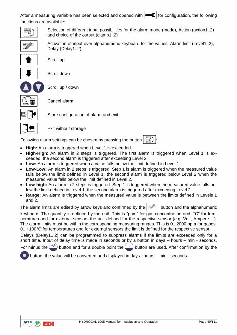
After a measuring variable has been selected and opened with for configuration, the following
functions are available:
Selection of different input possibilities for the alarm mode (mode), Action (action1..2) and choice of the output (clamp1..2)
Activation of input over alphanumeric keyboard for the values: Alarm limit (Level1..2), Delay (Delay1..2)
Scroll up
Scroll down
Scroll up / down
Cancel alarm
Store configuration of alarm and exit
Exit without storage
Following alarm settings can be chosen by pressing the button :
High: An alarm is triggered when Level 1 is exceeded.
High-High: An alarm in 2 steps is triggered. The first alarm is triggered when Level 1 is ex-ceeded; the second alarm is triggered after exceeding Level 2.
Low: An alarm is triggered when a value falls below the limit defined in Level 1.
Low-Low: An alarm in 2 steps is triggered. Step 1 is alarm is triggered when the measured value falls below the limit defined in Level 1, the second alarm is triggered below Level 2 when the measured value falls below the limit defined in Level 2.
Low-high: An alarm in 2 steps is triggered. Step 1 is triggered when the measured value falls be-low the limit defined in Level 1, the second alarm is triggered after exceeding Level 2.
Range: An alarm is triggered when the measured value is between the limits defined in Levels 1 and 2.
The alarm limits are edited by arrow keys and confirmed by the button and the alphanumeric
keyboard. The quantity is defined by the unit. This is “ppm” for gas concentration and „°C” for tem-peratures and for external sensors the unit defined for the respective sensor (e.g. Volt, Ampere ...). The alarm limits must be within the corresponding measuring ranges. This is 0...2000 ppm for gases, 0...+100°C for temperatures and for external sensors the limit is defined for the respective sensor.
Delays (Delay1...2) can be programmed to suppress alarms if the limits are exceeded only for a short time. Input of delay time is made in seconds or by a button in days – hours – min - seconds.
For minus the button and for a double point the button are used. After confirmation by the
button, the value will be converted and displayed in days –hours – min - seconds.
HYDROCAL 1005 Manual for Installation and Operation Page 50/111
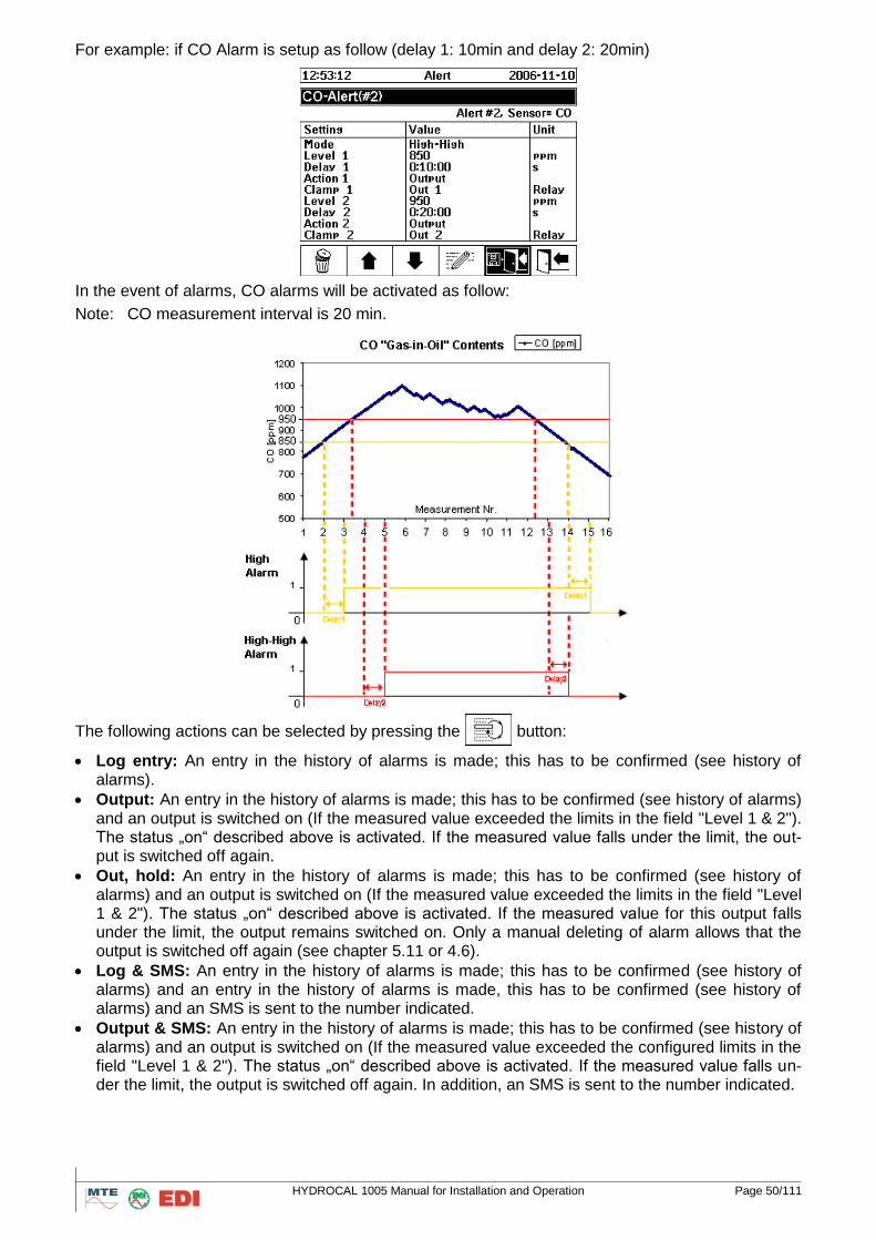
For example: if CO Alarm is setup as follow (delay 1: 10min and delay 2: 20min)
In the event of alarms, CO alarms will be activated as follow:
Note: CO measurement interval is 20 min.
The following actions can be selected by pressing the
button:
Log entry: An entry in the history of alarms is made; this has to be confirmed (see history of alarms).
Output: An entry in the history of alarms is made; this has to be confirmed (see history of alarms) and an output is switched on (If the measured value exceeded the limits in the field "Level 1 & 2"). The status „on“ described above is activated. If the measured value falls under the limit, the out-put is switched off again.
Out, hold: An entry in the history of alarms is made; this has to be confirmed (see history of alarms) and an output is switched on (If the measured value exceeded the limits in the field "Level 1 & 2"). The status „on“ described above is activated. If the measured value for this output falls under the limit, the output remains switched on. Only a manual deleting of alarm allows that the output is switched off again (see chapter 5.11 or 4.6).
Log & SMS: An entry in the history of alarms is made; this has to be confirmed (see history of alarms) and an entry in the history of alarms is made, this has to be confirmed (see history of alarms) and an SMS is sent to the number indicated.
Output & SMS: An entry in the history of alarms is made; this has to be confirmed (see history of alarms) and an output is switched on (If the measured value exceeded the configured limits in the field "Level 1 & 2"). The status „on“ described above is activated. If the measured value falls un-der the limit, the output is switched off again. In addition, an SMS is sent to the number indicated.
HYDROCAL 1005 Manual for Installation and Operation Page 51/111
Out, hold & SMS: An entry in the history of alarms is made; this has to be confirmed (see history of alarms) and an output is switched on (If the measured value exceeded the configured limits in the field "Level 1 & 2"). The status „on“ described above is activated. If the measured value for this output falls under the limit, the output remains switched on. Only a manual deleting of alarm allows that the output is switched off again (see chapter 4.11 or 3.6). In addition, an SMS is sent to the number indicated.
If it is possible to use the same output for different alarms and therefore, collection alarms can be defined.
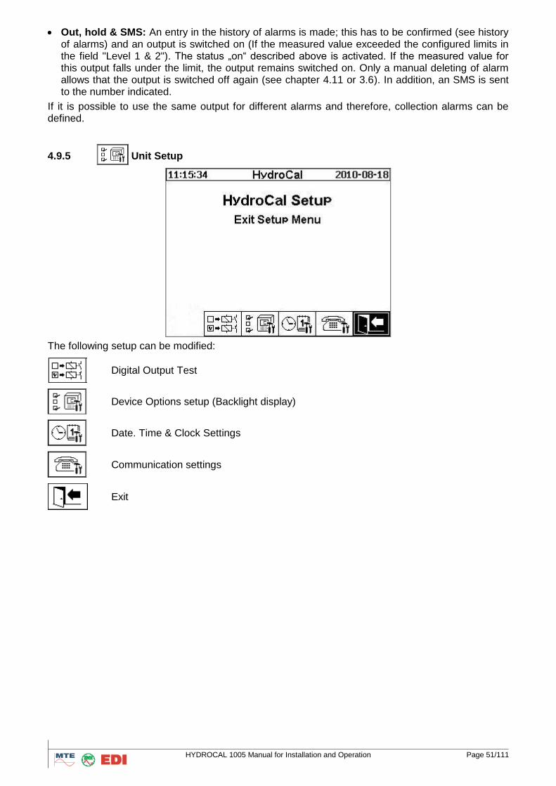
4.9.5 Unit Setup
The following setup can be modified:
Digital Output Test
Device Options setup (Backlight display)
Date. Time & Clock Settings
Communication settings
Exit
HYDROCAL 1005 Manual for Installation and Operation Page 52/111
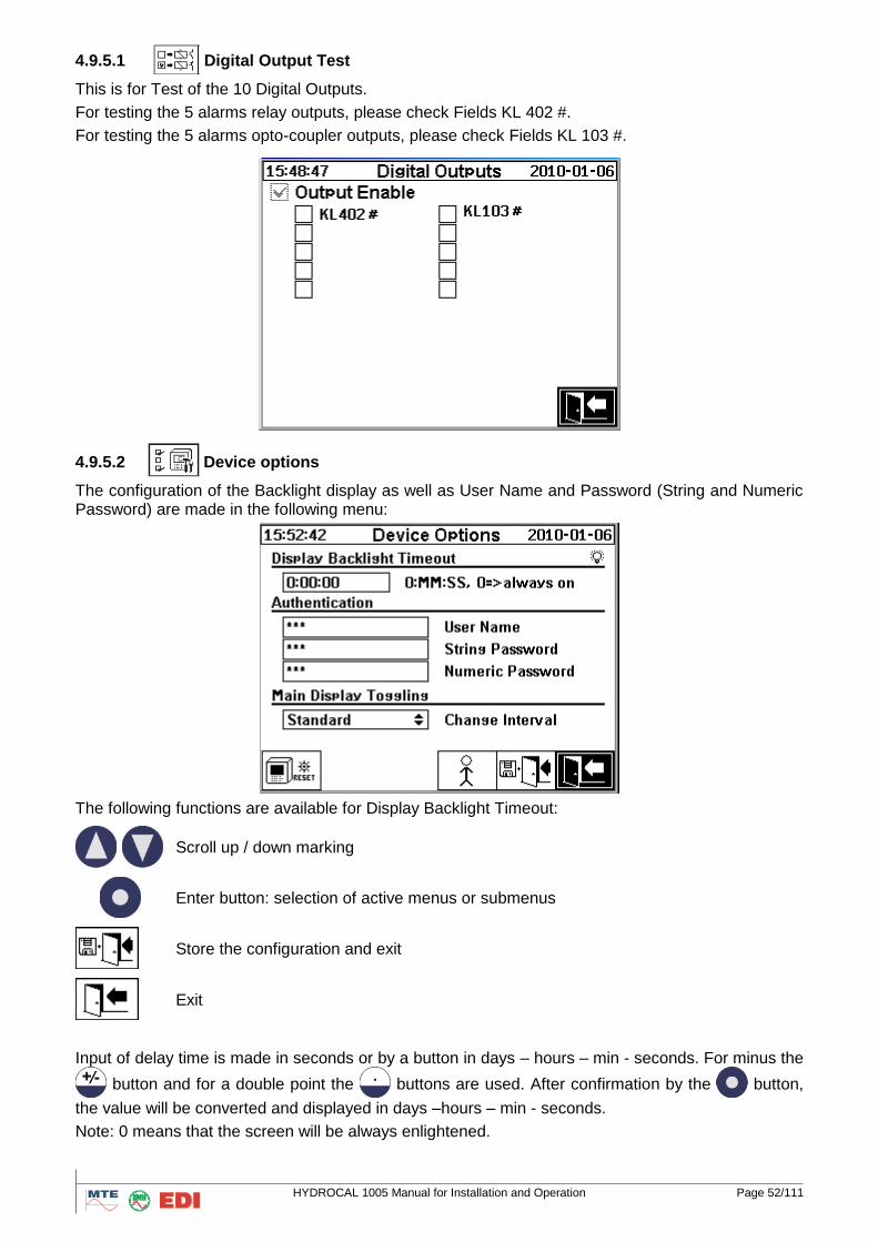
4.9.5.1 Digital Output Test
This is for Test of the 10 Digital Outputs.
For testing the 5 alarms relay outputs, please check Fields KL 402 #.
For testing the 5 alarms opto-coupler outputs, please check Fields KL 103 #.
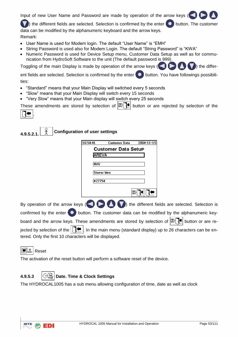
4.9.5.2 Device options
The configuration of the Backlight display as well as User Name and Password (String and Numeric Password) are made in the following menu:
The following functions are available for Display Backlight Timeout:
Scroll up / down marking
Enter button: selection of active menus or submenus
Store the configuration and exit
Exit
Input of delay time is made in seconds or by a button in days – hours – min - seconds. For minus the
button and for a double point the buttons are used. After confirmation by the button,
the value will be converted and displayed in days –hours – min - seconds.
Note: 0 means that the screen will be always enlightened.
HYDROCAL 1005 Manual for Installation and Operation Page 53/111
Input of new User Name and Password are made by operation of the arrow keys (
) the different fields are selected. Selection is confirmed by the enter button. The customer
data can be modified by the alphanumeric keyboard and the arrow keys.
Remark:
User Name is used for Modem login. The default “User Name” is “EMH”
String Password is used also for Modem Login. The default “String Password” is “KWA”
Numeric Password is used for Device Setup menu, Customer Data Setup as well as for commu-nication from HydroSoft Software to the unit (The default password is 999).
Toggling of the main Display is made by operation of the arrow keys (
) the differ-
ent fields are selected. Selection is confirmed by the enter button. You have followings possibili-
ties:
“Standard” means that your Main Display will switched every 5 seconds
“Slow” means that your Main Display will switch every 15 seconds
“Very Slow” means that your Main display will switch every 25 seconds
These amendments are stored by selection of button or are rejected by selection of the
.
4.9.5.2.1. Configuration of user settings
By operation of the arrow keys (
) the different fields are selected. Selection is
confirmed by the enter button. The customer data can be modified by the alphanumeric key-
board and the arrow keys. These amendments are stored by selection of button or are re-
jected by selection of the . In the main menu (standard display) up to 26 characters can be en-
tered. Only the first 10 characters will be displayed.
Reset
The activation of the reset button will perform a software reset of the device.
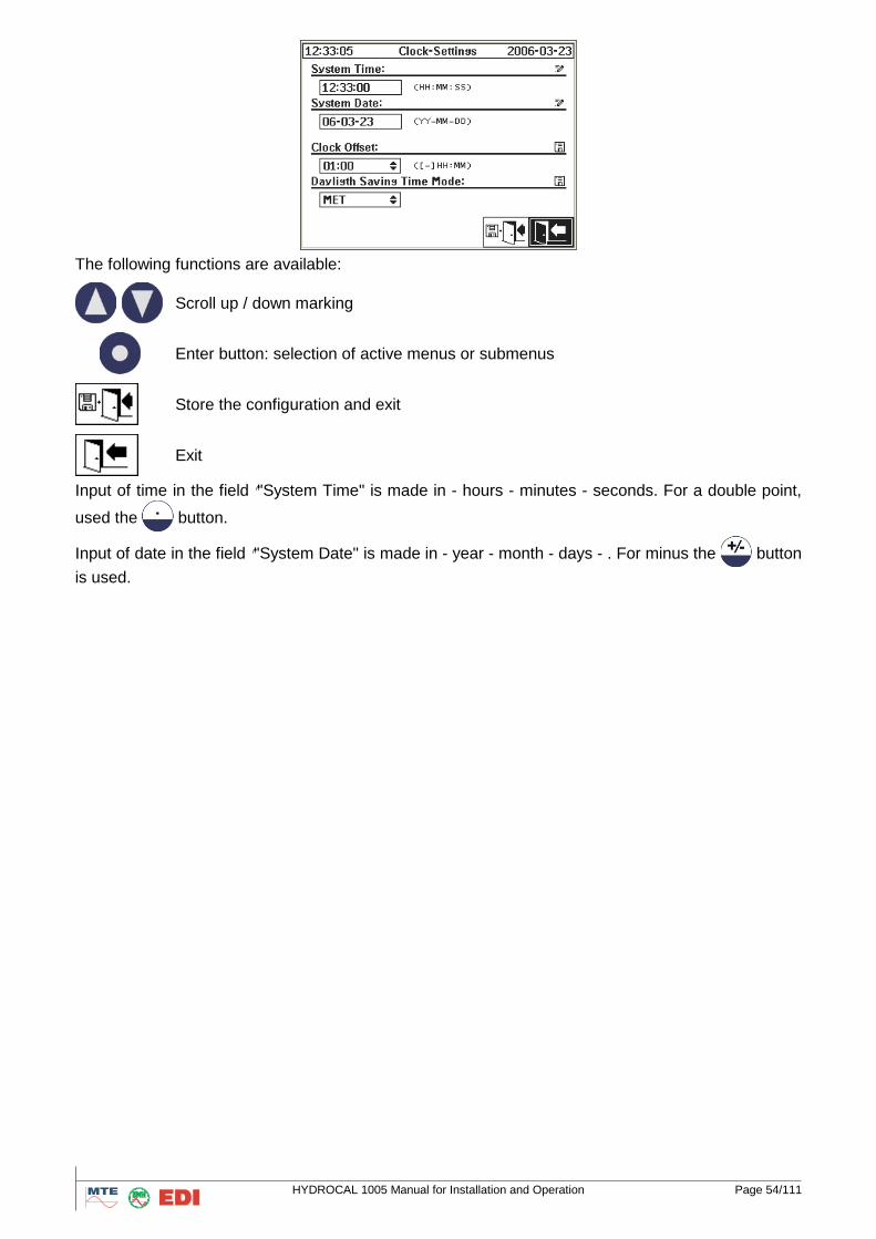
4.9.5.3 Date. Time & Clock Settings
The HYDROCAL1005 has a sub menu allowing configuration of time, date as well as clock
HYDROCAL 1005 Manual for Installation and Operation Page 54/111
The following functions are available:
Scroll up / down marking
Enter button: selection of active menus or submenus
Store the configuration and exit
Exit
Input of time in the field ""System Time" is made in - hours - minutes - seconds. For a double point,
used the button.
Input of date in the field ""System Date" is made in - year - month - days - . For minus the button
is used.
HYDROCAL 1005 Manual for Installation and Operation Page 55/111
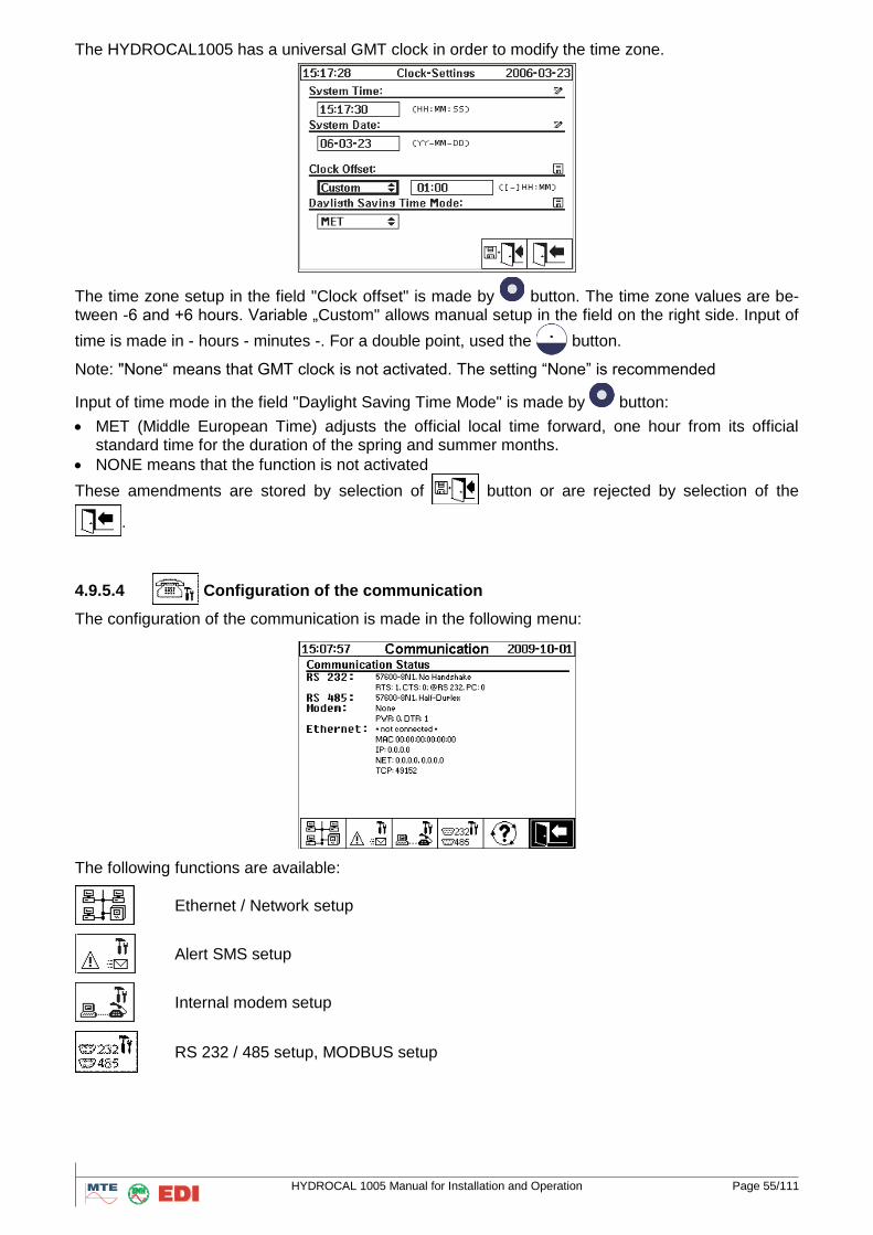
The HYDROCAL1005 has a universal GMT clock in order to modify the time zone.
The time zone setup in the field "Clock offset" is made by button. The time zone values are be-tween -6 and +6 hours. Variable „Custom" allows manual setup in the field on the right side. Input of
time is made in - hours - minutes -. For a double point, used the button.
Note: "None“ means that GMT clock is not activated. The setting “None” is recommended
Input of time mode in the field "Daylight Saving Time Mode" is made by button:
MET (Middle European Time) adjusts the official local time forward, one hour from its official standard time for the duration of the spring and summer months.
NONE means that the function is not activated
These amendments are stored by selection of button or are rejected by selection of the
.
4.9.5.4
Configuration of the communication
The configuration of the communication is made in the following menu:
The following functions are available:
Ethernet / Network setup
Alert SMS setup
Internal modem setup
RS 232 / 485 setup, MODBUS setup
HYDROCAL 1005 Manual for Installation and Operation Page 56/111
Status information activation
Scroll up / down marking
Enter button: selection of active menus or submenus
Exit
Note: on the main display, you have the currently communication status.
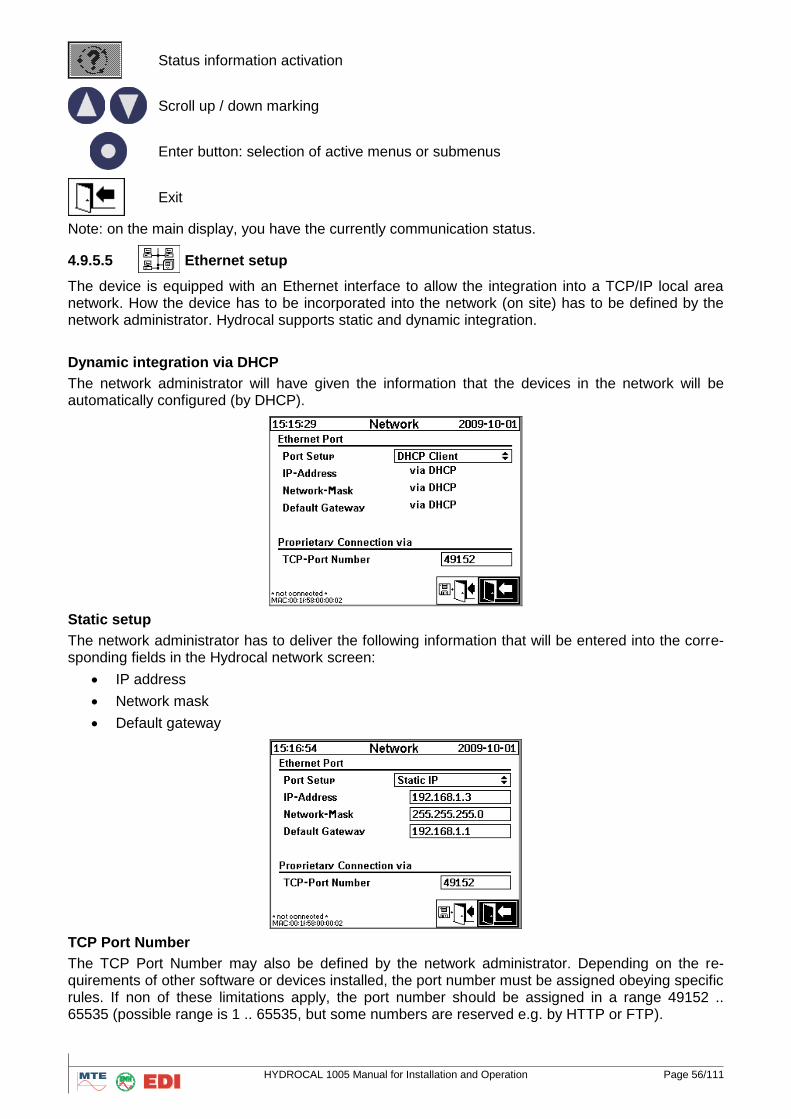
4.9.5.5 Ethernet setup
The device is equipped with an Ethernet interface to allow the integration into a TCP/IP local area network. How the device has to be incorporated into the network (on site) has to be defined by the network administrator. Hydrocal supports static and dynamic integration.
Dynamic integration via DHCP
The network administrator will have given the information that the devices in the network will be automatically configured (by DHCP).
Static setup
The network administrator has to deliver the following information that will be entered into the corre-sponding fields in the Hydrocal network screen:
IP address
Network mask
Default gateway
TCP Port Number
The TCP Port Number may also be defined by the network administrator. Depending on the re-quirements of other software or devices installed, the port number must be assigned obeying specific rules. If non of these limitations apply, the port number should be assigned in a range 49152 .. 65535 (possible range is 1 .. 65535, but some numbers are reserved e.g. by HTTP or FTP).
HYDROCAL 1005 Manual for Installation and Operation Page 57/111
Remark: For test purposes a DHCP server can be activated on the device. This feature is only im-plemented to allow the connection of a laptop / portable computer with Windows standard network configuration. Only for the time of the test the DHCP server would be activated, allowing service staff to communicate with the device via Ethernet. The device is not designed to serve as a real DHCP server in a real network environment.
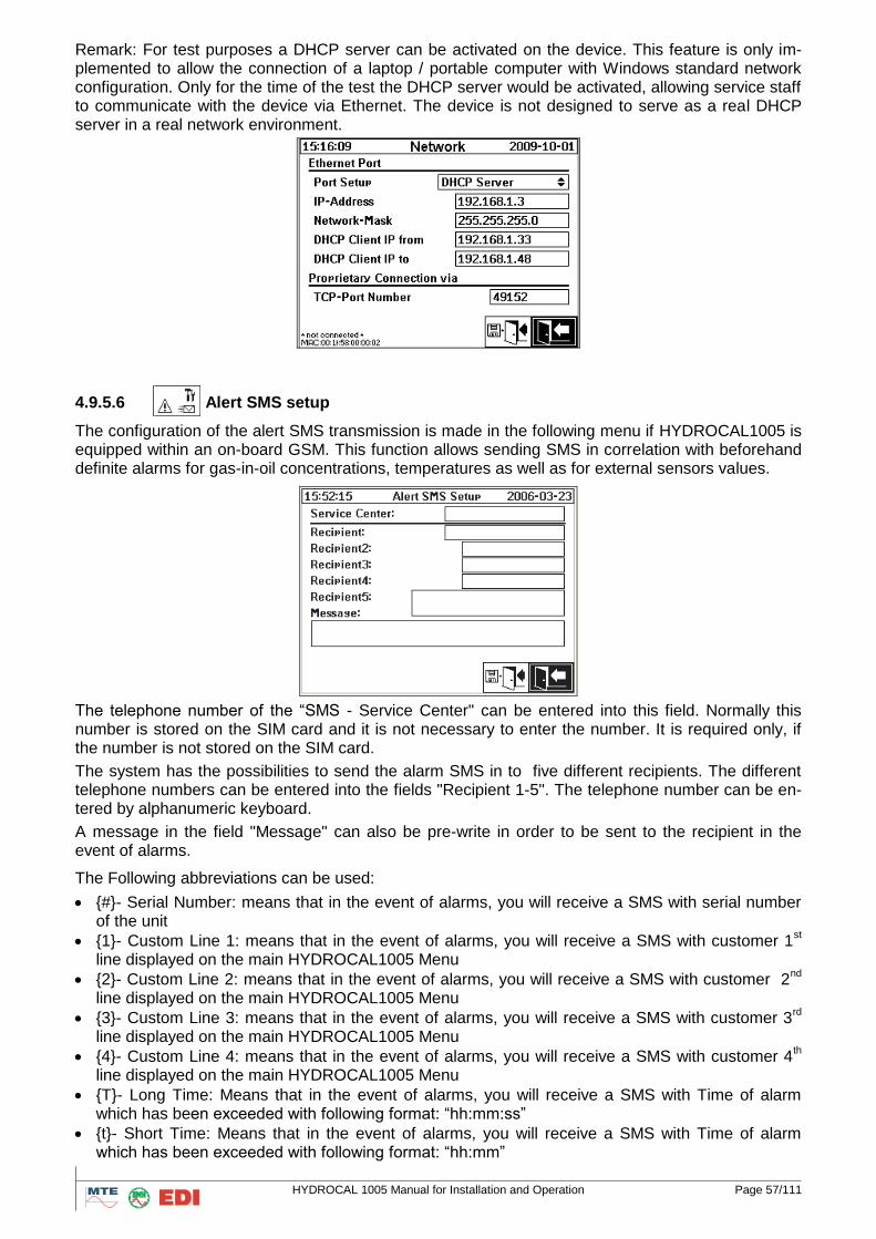
4.9.5.6 Alert SMS setup
The configuration of the alert SMS transmission is made in the following menu if HYDROCAL1005 is equipped within an on-board GSM. This function allows sending SMS in correlation with beforehand definite alarms for gas-in-oil concentrations, temperatures as well as for external sensors values.
The telephone number of the “SMS - Service Center" can be entered into this field. Normally this number is stored on the SIM card and it is not necessary to enter the number. It is required only, if the number is not stored on the SIM card.
The system has the possibilities to send the alarm SMS in to five different recipients. The different telephone numbers can be entered into the fields "Recipient 1-5". The telephone number can be en-tered by alphanumeric keyboard.
A message in the field "Message" can also be pre-write in order to be sent to the recipient in the event of alarms.
The Following abbreviations can be used:
{#}- Serial Number: means that in the event of alarms, you will receive a SMS with serial number of the unit
{1}- Custom Line 1: means that in the event of alarms, you will receive a SMS with customer 1st
line displayed on the main HYDROCAL1005 Menu
{2}- Custom Line 2: means that in the event of alarms, you will receive a SMS with customer 2nd
line displayed on the main HYDROCAL1005 Menu
{3}- Custom Line 3: means that in the event of alarms, you will receive a SMS with customer 3rd
line displayed on the main HYDROCAL1005 Menu
{4}- Custom Line 4: means that in the event of alarms, you will receive a SMS with customer 4th
line displayed on the main HYDROCAL1005 Menu
{T}- Long Time: Means that in the event of alarms, you will receive a SMS with Time of alarm which has been exceeded with following format: “hh:mm:ss”
{t}- Short Time: Means that in the event of alarms, you will receive a SMS with Time of alarm which has been exceeded with following format: “hh:mm”
HYDROCAL 1005 Manual for Installation and Operation Page 58/111
{D}- Long Date: Means that in the event of alarms, you will receive a SMS with Date of alarm which has been exceeded with following format: “YYYY:MM:DD”
{d}- Short Date: Means that in the event of alarms, you will receive a SMS with Date of alarm which has been exceeded with following format: “YY:MM:DD”
{A}- Alert Name: means that in the event of alarms, you will receive a SMS with the alarm Name
{a}- Alert Number: means that in the event of alarms, you will receive a SMS with Alert Number
{l}- Alert Level: means that in the event of alarms, you will receive a SMS with Alert Level (“1” for a High alarm or Level 1 and “2” for a High-High alarm or Level 2)
Note: The SMS mode (in Alarm set-up) must be selected to use this function. Moreover, GSM mo-dem must be also installed on HYDROCAL1005.
These amendments are stored by selection of button or are rejected by selection of the
.
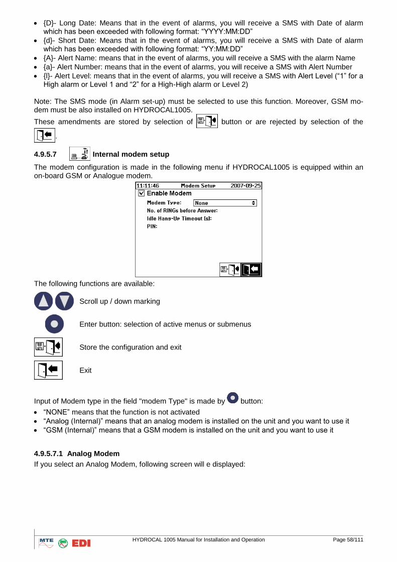
4.9.5.7 Internal modem setup
The modem configuration is made in the following menu if HYDROCAL1005 is equipped within an on-board GSM or Analogue modem.
The following functions are available:
Scroll up / down marking
Enter button: selection of active menus or submenus
Store the configuration and exit
Exit
Input of Modem type in the field "modem Type" is made by button:
“NONE” means that the function is not activated
“Analog (Internal)” means that an analog modem is installed on the unit and you want to use it
“GSM (Internal)” means that a GSM modem is installed on the unit and you want to use it
4.9.5.7.1 Analog Modem
If you select an Analog Modem, following screen will e displayed:
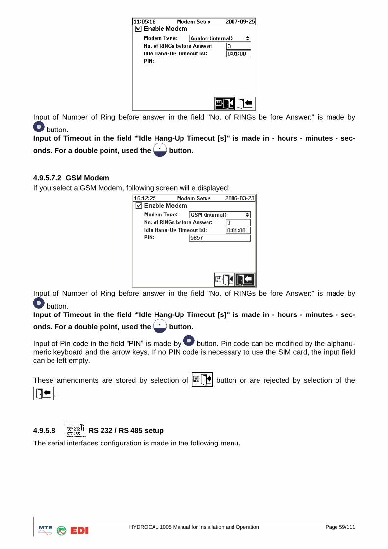
HYDROCAL 1005 Manual for Installation and Operation Page 59/111
Input of Number of Ring before answer in the field "No. of RINGs be fore Answer:" is made by
button.
Input of Timeout in the field ""Idle Hang-Up Timeout [s]" is made in - hours - minutes - sec-
onds. For a double point, used the button.
4.9.5.7.2 GSM Modem
If you select a GSM Modem, following screen will e displayed:
Input of Number of Ring before answer in the field "No. of RINGs be fore Answer:" is made by
button.
Input of Timeout in the field ""Idle Hang-Up Timeout [s]" is made in - hours - minutes - sec-
onds. For a double point, used the button.
Input of Pin code in the field “PIN” is made by button. Pin code can be modified by the alphanu-meric keyboard and the arrow keys. If no PIN code is necessary to use the SIM card, the input field can be left empty.
These amendments are stored by selection of button or are rejected by selection of the
.
4.9.5.8 RS 232 / RS 485 setup
The serial interfaces configuration is made in the following menu.
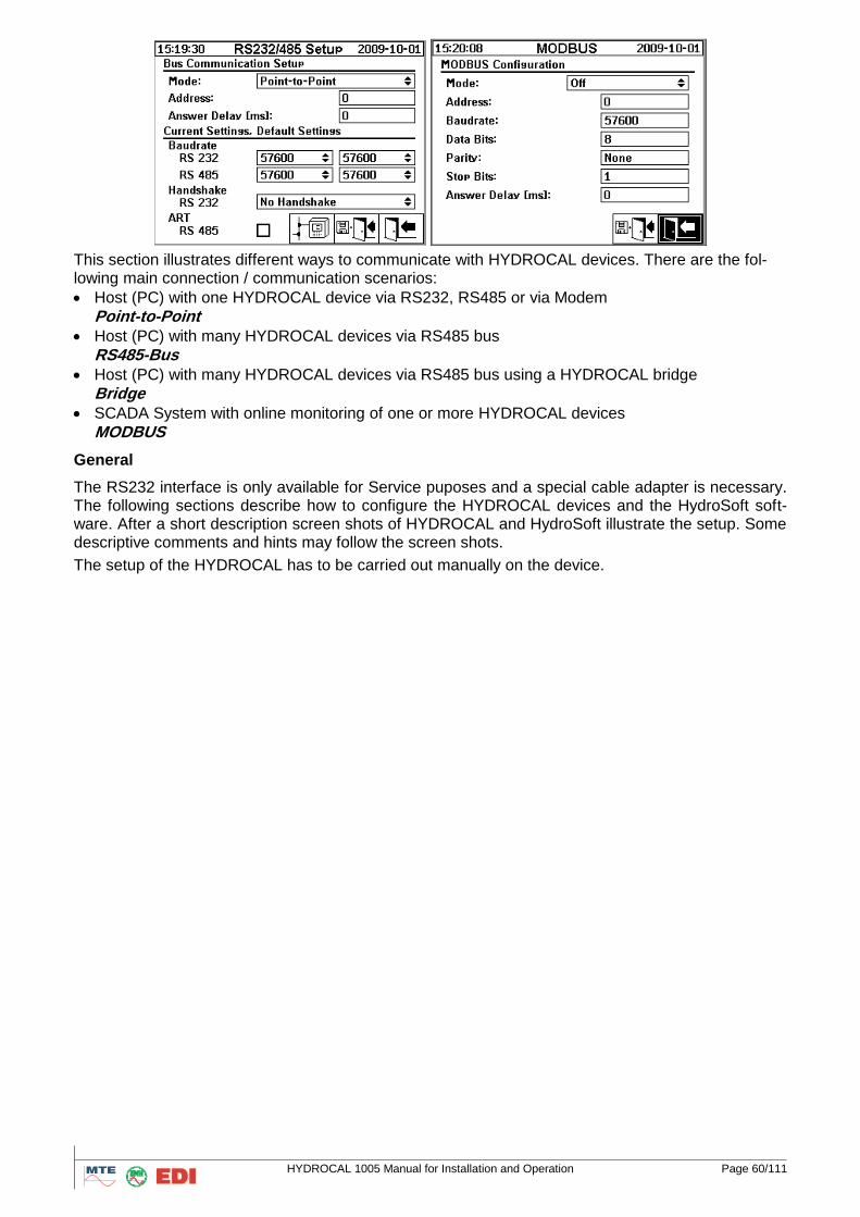
HYDROCAL 1005 Manual for Installation and Operation Page 60/111
This section illustrates different ways to communicate with HYDROCAL devices. There are the fol-lowing main connection / communication scenarios:
Host (PC) with one HYDROCAL device via RS232, RS485 or via Modem
Point-to-Point Host (PC) with many HYDROCAL devices via RS485 bus
RS485-Bus
Host (PC) with many HYDROCAL devices via RS485 bus using a HYDROCAL bridge
Bridge
SCADA System with online monitoring of one or more HYDROCAL devices
MODBUS
General
The RS232 interface is only available for Service puposes and a special cable adapter is necessary. The following sections describe how to configure the HYDROCAL devices and the HydroSoft soft-ware. After a short description screen shots of HYDROCAL and HydroSoft illustrate the setup. Some descriptive comments and hints may follow the screen shots.
The setup of the HYDROCAL has to be carried out manually on the device.
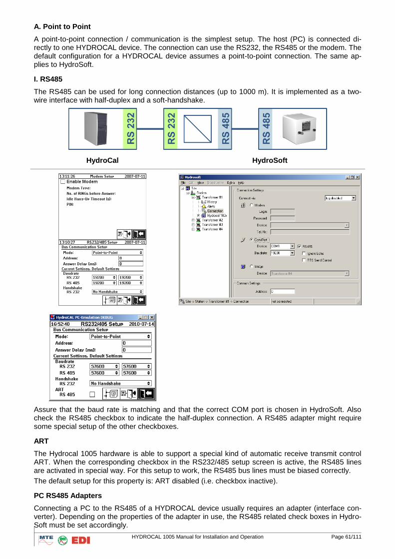
HYDROCAL 1005 Manual for Installation and Operation Page 61/111
A. Point to Point
A point-to-point connection / communication is the simplest setup. The host (PC) is connected di-rectly to one HYDROCAL device. The connection can use the RS232, the RS485 or the modem. The default configuration for a HYDROCAL device assumes a point-to-point connection. The same ap-plies to HydroSoft.
I. RS485
The RS485 can be used for long connection distances (up to 1000 m). It is implemented as a two-wire interface with half-duplex and a soft-handshake.
HydroCal HydroSoft
Assure that the baud rate is matching and that the correct COM port is chosen in HydroSoft. Also check the RS485 checkbox to indicate the half-duplex connection. A RS485 adapter might require some special setup of the other checkboxes.
ART
The Hydrocal 1005 hardware is able to support a special kind of automatic receive transmit control ART. When the corresponding checkbox in the RS232/485 setup screen is active, the RS485 lines are activated in special way. For this setup to work, the RS485 bus lines must be biased correctly.
The default setup for this property is: ART disabled (i.e. checkbox inactive).
PC RS485 Adapters
Connecting a PC to the RS485 of a HYDROCAL device usually requires an adapter (interface con-verter). Depending on the properties of the adapter in use, the RS485 related check boxes in Hydro-Soft must be set accordingly.
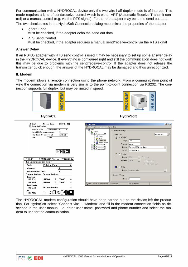
HYDROCAL 1005 Manual for Installation and Operation Page 62/111
For communication with a HYDROCAL device only the two-wire half-duplex mode is of interest. This mode requires a kind of send/receive-control which is either ART (Automatic Receive Transmit con-trol) or a manual control (e.g. via the RTS signal). Further the adapter may echo the send out data.
The two checkboxes in the HydroSoft Connection dialog must mirror the properties of the adapter:
Ignore Echo Must be checked, if the adapter echo the send out data
RTS Send Control Must be checked, if the adapter requires a manual send/receive-control via the RTS signal
Answer Delay
If an RS485 adapter with RTS send control is used it may be necessary to set up some answer delay in the HYDROCAL device. If everything is configured right and still the communication does not work this may be due to problems with the send/receive-control. If the adapter does not release the transmitter quick enough, the answer of the HYDROCAL may be damaged and thus unrecognized.
II. Modem
The modem allows a remote connection using the phone network. From a communication point of view the connection via modem is very similar to the point-to-point connection via RS232. The con-nection supports full duplex, but may be limited in speed.
HydroCal HydroSoft
The HYDROCAL modem configuration should have been carried out as the device left the produc-tion. For HydroSoft select "Connect via:" - "Modem" and fill in the modem connection fields as de-scribed in the user manual, i.e. enter user name, password and phone number and select the mo-dem to use for the communication.
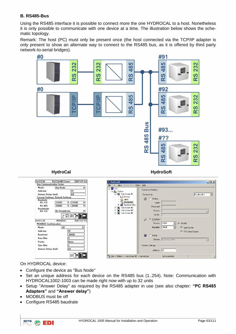
HYDROCAL 1005 Manual for Installation and Operation Page 63/111
B. RS485-Bus
Using the RS485 interface it is possible to connect more the one HYDROCAL to a host. Nonetheless it is only possible to communicate with one device at a time. The illustration below shows the sche-matic topology.
Remark: The host (PC) must only be present once (the host connected via the TCP/IP adapter is only present to show an alternate way to connect to the RS485 bus, as it is offered by third party network-to-serial bridges).
HydroCal HydroSoft
On HYDROCAL device:
Configure the device as "Bus Node"
Set an unique address for each device on the RS485 bus (1..254). Note: Communication with HYDROCAL1002-1003 can be made right now with up to 32 units
Setup "Answer Delay" as required by the RS485 adapter in use (see also chapter: “PC RS485
Adapters” and “Answer delay”)
MODBUS must be off
Configure RS485 baudrate
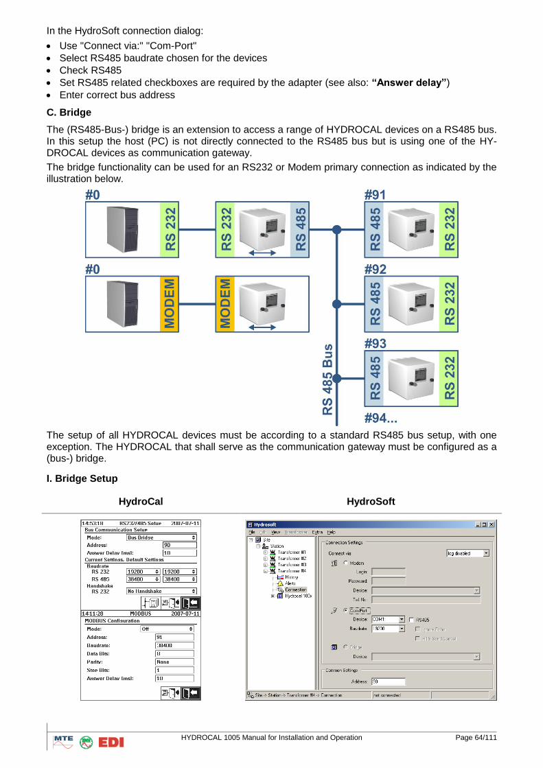
HYDROCAL 1005 Manual for Installation and Operation Page 64/111
In the HydroSoft connection dialog:
Use "Connect via:" "Com-Port"
Select RS485 baudrate chosen for the devices
Check RS485
Set RS485 related checkboxes are required by the adapter (see also: “Answer delay”)
Enter correct bus address
C. Bridge
The (RS485-Bus-) bridge is an extension to access a range of HYDROCAL devices on a RS485 bus. In this setup the host (PC) is not directly connected to the RS485 bus but is using one of the HY-DROCAL devices as communication gateway.
The bridge functionality can be used for an RS232 or Modem primary connection as indicated by the illustration below.
The setup of all HYDROCAL devices must be according to a standard RS485 bus setup, with one exception. The HYDROCAL that shall serve as the communication gateway must be configured as a (bus-) bridge.
I. Bridge Setup
HydroCal HydroSoft
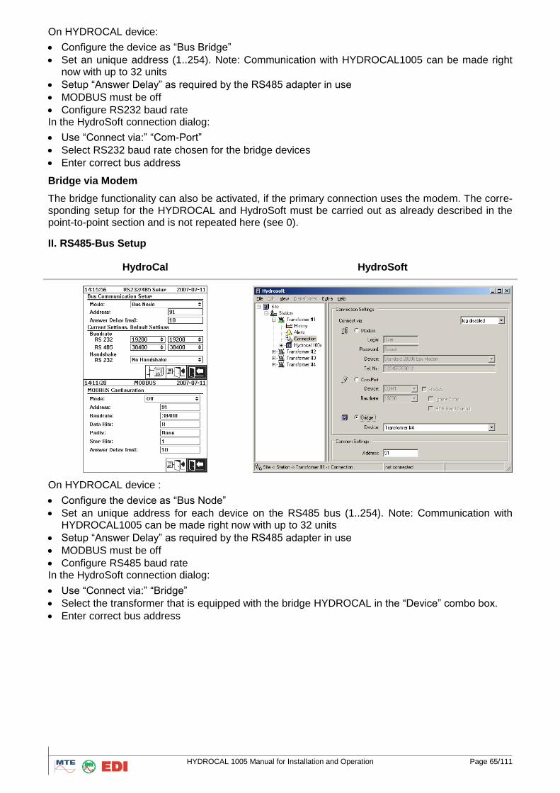
HYDROCAL 1005 Manual for Installation and Operation Page 65/111
On HYDROCAL device:
Configure the device as “Bus Bridge”
Set an unique address (1..254). Note: Communication with HYDROCAL1005 can be made right now with up to 32 units
Setup “Answer Delay” as required by the RS485 adapter in use
MODBUS must be off
Configure RS232 baud rate In the HydroSoft connection dialog:
Use “Connect via:” “Com-Port”
Select RS232 baud rate chosen for the bridge devices
Enter correct bus address
Bridge via Modem
The bridge functionality can also be activated, if the primary connection uses the modem. The corre-sponding setup for the HYDROCAL and HydroSoft must be carried out as already described in the point-to-point section and is not repeated here (see 0).
II. RS485-Bus Setup
HydroCal HydroSoft
On HYDROCAL device :
Configure the device as “Bus Node”
Set an unique address for each device on the RS485 bus (1..254). Note: Communication with HYDROCAL1005 can be made right now with up to 32 units
Setup “Answer Delay” as required by the RS485 adapter in use
MODBUS must be off
Configure RS485 baud rate In the HydroSoft connection dialog:
Use “Connect via:” “Bridge”
Select the transformer that is equipped with the bridge HYDROCAL in the “Device” combo box.
Enter correct bus address
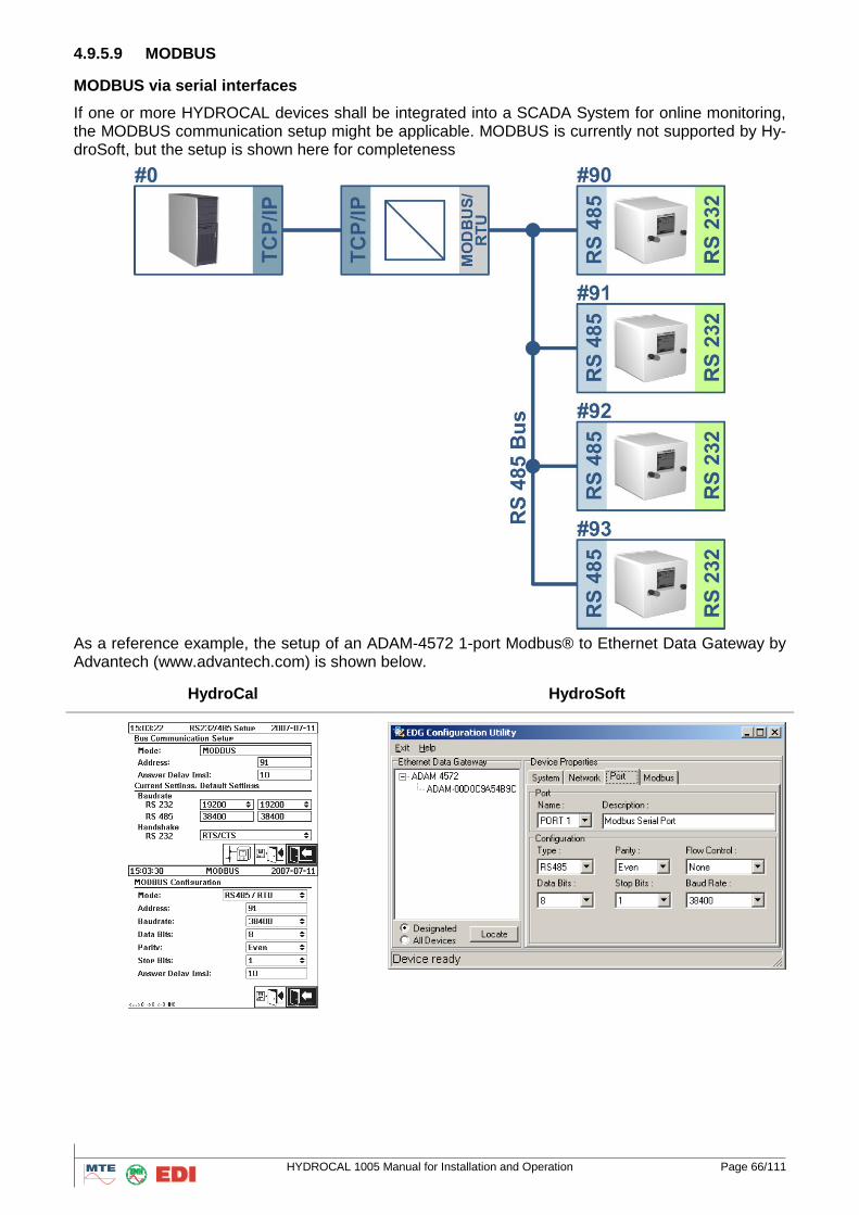
HYDROCAL 1005 Manual for Installation and Operation Page 66/111
4.9.5.9 MODBUS
MODBUS via serial interfaces
If one or more HYDROCAL devices shall be integrated into a SCADA System for online monitoring, the MODBUS communication setup might be applicable. MODBUS is currently not supported by Hy-droSoft, but the setup is shown here for completeness
As a reference example, the setup of an ADAM-4572 1-port Modbus® to Ethernet Data Gateway by Advantech (www.advantech.com) is shown below.
HydroCal HydroSoft
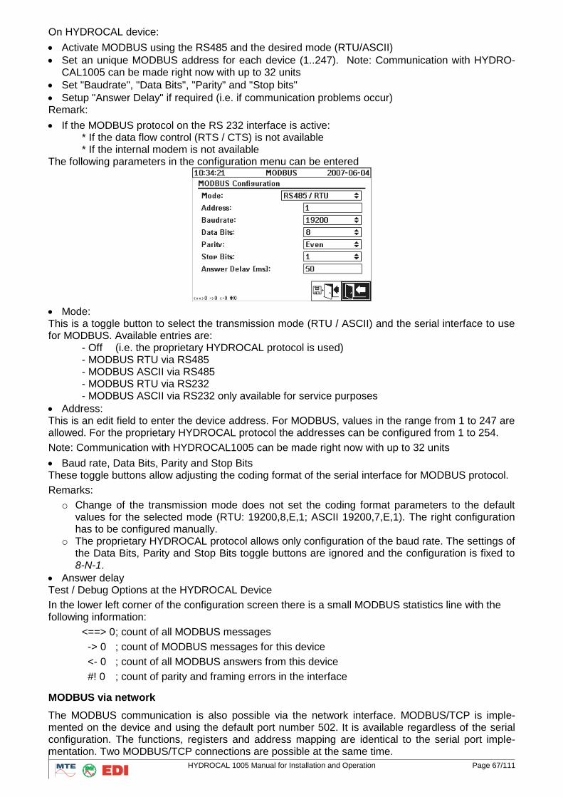
HYDROCAL 1005 Manual for Installation and Operation Page 67/111
On HYDROCAL device:
Activate MODBUS using the RS485 and the desired mode (RTU/ASCII)
Set an unique MODBUS address for each device (1..247). Note: Communication with HYDRO-CAL1005 can be made right now with up to 32 units
Set "Baudrate", "Data Bits", "Parity" and "Stop bits"
Setup "Answer Delay" if required (i.e. if communication problems occur) Remark:
If the MODBUS protocol on the RS 232 interface is active: * If the data flow control (RTS / CTS) is not available * If the internal modem is not available
The following parameters in the configuration menu can be entered
Mode: This is a toggle button to select the transmission mode (RTU / ASCII) and the serial interface to use for MODBUS. Available entries are: - Off (i.e. the proprietary HYDROCAL protocol is used) - MODBUS RTU via RS485 - MODBUS ASCII via RS485 - MODBUS RTU via RS232 - MODBUS ASCII via RS232 only available for service purposes
Address: This is an edit field to enter the device address. For MODBUS, values in the range from 1 to 247 are allowed. For the proprietary HYDROCAL protocol the addresses can be configured from 1 to 254.
Note: Communication with HYDROCAL1005 can be made right now with up to 32 units
Baud rate, Data Bits, Parity and Stop Bits These toggle buttons allow adjusting the coding format of the serial interface for MODBUS protocol.
Remarks:
o Change of the transmission mode does not set the coding format parameters to the default values for the selected mode (RTU: 19200,8,E,1; ASCII 19200,7,E,1). The right configuration has to be configured manually.
o The proprietary HYDROCAL protocol allows only configuration of the baud rate. The settings of the Data Bits, Parity and Stop Bits toggle buttons are ignored and the configuration is fixed to 8-N-1.
Answer delay Test / Debug Options at the HYDROCAL Device
In the lower left corner of the configuration screen there is a small MODBUS statistics line with the following information:
<==> 0 ; count of all MODBUS messages
-> 0 ; count of MODBUS messages for this device
<- 0 ; count of all MODBUS answers from this device
#! 0 ; count of parity and framing errors in the interface
MODBUS via network
The MODBUS communication is also possible via the network interface. MODBUS/TCP is imple-mented on the device and using the default port number 502. It is available regardless of the serial configuration. The functions, registers and address mapping are identical to the serial port imple-mentation. Two MODBUS/TCP connections are possible at the same time.
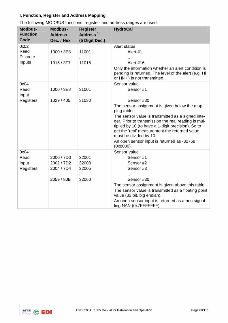
HYDROCAL 1005 Manual for Installation and Operation Page 68/111
I. Function, Register and Address Mapping
The following MODBUS functions, register- and address ranges are used:
Modbus-
Function
Code
Modbus-
Address
Dec. / Hex
Register
Address 1)
(5 Digit Dec.)
HydroCal
0x02 Read
Discrete
Inputs
1000 / 3E8
..
1015 / 3F7
11001
..
11016
Alert status
Alert #1
..
Alert #16
Only the information whether an alert condition is pending is returned. The level of the alert (e.g. Hi or Hi-Hi) is not transmitted.
0x04
Read
Input
Registers
1000 / 3E8
..
1029 / 405
31001
..
31030
Sensor value
Sensor #1
..
Sensor #30
The sensor assignment is given below the map-ping tables.
The sensor value is transmitted as a signed inte-ger. Prior to transmission the real reading is mul-tiplied by 10 (to have a 1-digit precision). So to get the 'real' measurement the returned value must be divided by 10.
An open sensor input is returned as -32768 (0x8000).
0x04
Read
Input
Registers
2000 / 7D0
2002 / 7D2
2004 / 7D4
..
2059 / 80B
32001
32003
32005
..
32060
Sensor value
Sensor #1
Sensor #2
Sensor #3
..
Sensor #30
The sensor assignment is given above this table.
The sensor value is transmitted as a floating point value (32 bit, big endian).
An open sensor input is returned as a non signal-ling NAN (0x7FFFFFFF).
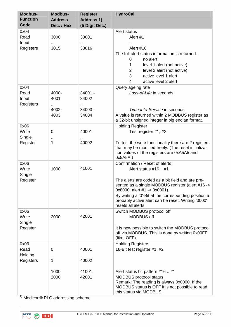
HYDROCAL 1005 Manual for Installation and Operation Page 69/111
Modbus-
Function
Code
Modbus-
Address
Dec. / Hex
Register
Address 1)
(5 Digit Dec.)
HydroCal
0x04
Read
Input
Registers
3000
..
3015
33001
..
33016
Alert status
Alert #1
..
Alert #16
The full alert status information is returned.
0 no alert
1 level 1 alert (not active)
2 level 2 alert (not active)
3 active level 1 alert
4 active level 2 alert
0x04
Read
Input
Registers
4000-
4001
..
4002-
4003
34001 -
34002
..
34003 -
34004
Query ageing rate
Loss-of-Life in seconds
Time-into-Service in seconds
A value is returned within 2 MODBUS register as a 32-bit unsigned integer in big endian format.
0x06
Write
Single
Register
0
..
1
40001
..
40002
Holding Register
Test register #1, #2
To test the write functionality there are 2 registers that may be modified freely. (The reset initializa-tion values of the registers are 0xA5A5 and 0x5A5A.)
0x06
Write
Single
Register
1000
41001
Confirmation / Reset of alerts
Alert status #16 .. #1
The alerts are coded as a bit field and are pre-sented as a single MODBUS register (alert #16 -> 0x8000, alert #1 -> 0x0001).
By writing a '0'-Bit at the corresponding position a probably active alert can be reset. Writing '0000' resets all alerts.
0x06
Write
Single
Register
2000
42001
Switch MODBUS protocol off
MODBUS off
It is now possible to switch the MODBUS protocol off via MODBUS. This is done by writing 0x00FF (like OFF).
0x03
Read
Holding
Registers
0
..
1
1000
2000
40001
..
40002
41001
42001
Holding Registers
16-Bit test register #1, #2
Alert status bit pattern #16 .. #1
MODBUS protocol status Remark: The reading is always 0x0000. If the MODBUS status is OFF it is not possible to read this status via MODBUS.
1) Modicon® PLC addressing scheme
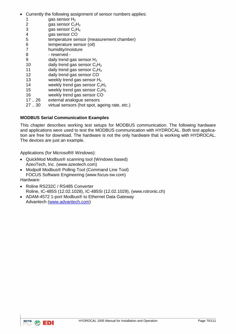
HYDROCAL 1005 Manual for Installation and Operation Page 70/111
Currently the following assignment of sensor numbers applies: 1 gas sensor H2 2 gas sensor C2H2 3 gas sensor C2H4 4 gas sensor CO 5 temperature sensor (measurement chamber) 6 temperature sensor (oil) 7 humidity/moisture 8 - reserved - 9 daily trend gas sensor H2 10 daily trend gas sensor C2H2 11 daily trend gas sensor C2H4 12 daily trend gas sensor CO 13 weekly trend gas sensor H2 14 weekly trend gas sensor C2H2 15 weekly trend gas sensor C2H4 16 weekly trend gas sensor CO 17 .. 26 external analogue sensors 27 .. 30 virtual sensors (hot spot, ageing rate, etc.)
MODBUS Serial Communication Examples
This chapter describes working test setups for MODBUS communication. The following hardware and applications were used to test the MODBUS communication with HYDROCAL. Both test applica-tion are free for download. The hardware is not the only hardware that is working with HYDROCAL. The devices are just an example.
Applications (for Microsoft® Windows):
QuickMod Modbus® scanning tool (Windows based) AzeoTech, Inc. (www.azeotech.com)
Modpoll Modbus® Polling Tool (Command Line Tool) FOCUS Software Engineering (www.focus-sw.com)
Hardware:
Roline RS232C / RS485 Converter Roline, IC-485S (12.02.1028), IC-485SI (12.02.1029), (www.rotronic.ch)
ADAM-4572 1-port Modbus® to Ethernet Data Gateway Advantech (www.advantech.com)
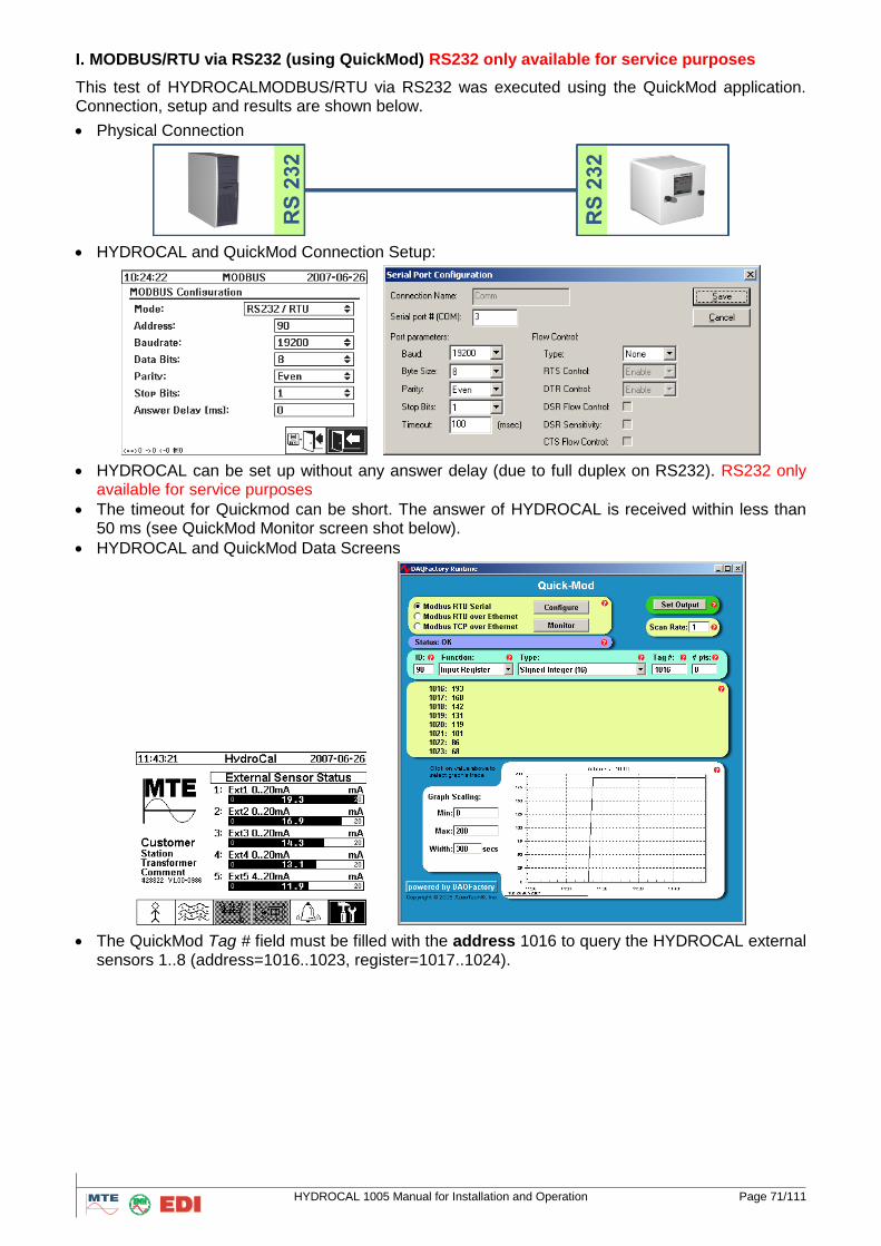
HYDROCAL 1005 Manual for Installation and Operation Page 71/111
I. MODBUS/RTU via RS232 (using QuickMod) RS232 only available for service purposes
This test of HYDROCALMODBUS/RTU via RS232 was executed using the QuickMod application. Connection, setup and results are shown below.
Physical Connection
HYDROCAL and QuickMod Connection Setup:
HYDROCAL can be set up without any answer delay (due to full duplex on RS232). RS232 only available for service purposes
The timeout for Quickmod can be short. The answer of HYDROCAL is received within less than 50 ms (see QuickMod Monitor screen shot below).
HYDROCAL and QuickMod Data Screens
The QuickMod Tag # field must be filled with the address 1016 to query the HYDROCAL external sensors 1..8 (address=1016..1023, register=1017..1024).
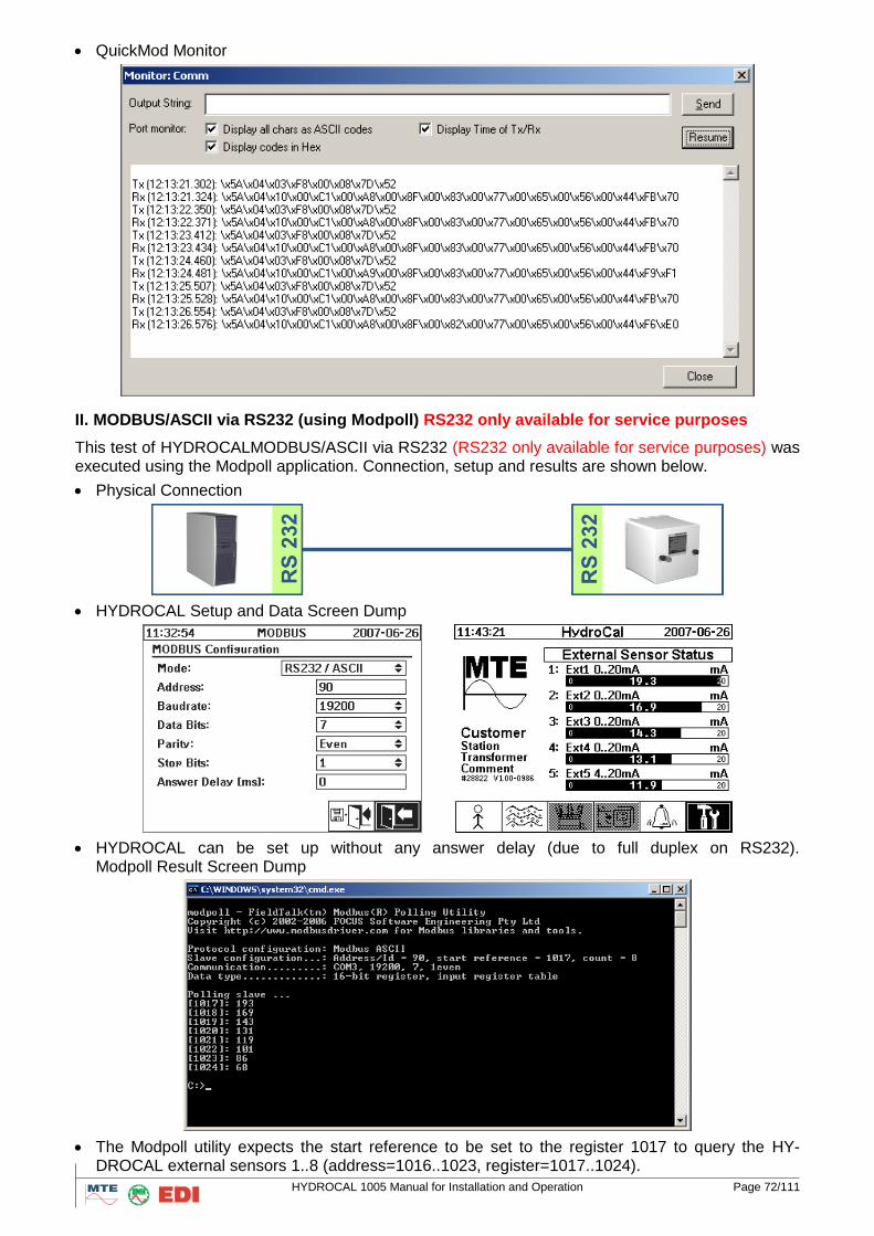
HYDROCAL 1005 Manual for Installation and Operation Page 72/111
QuickMod Monitor
II. MODBUS/ASCII via RS232 (using Modpoll) RS232 only available for service purposes
This test of HYDROCALMODBUS/ASCII via RS232 (RS232 only available for service purposes) was executed using the Modpoll application. Connection, setup and results are shown below.
Physical Connection
HYDROCAL Setup and Data Screen Dump
HYDROCAL can be set up without any answer delay (due to full duplex on RS232). Modpoll Result Screen Dump
The Modpoll utility expects the start reference to be set to the register 1017 to query the HY-DROCAL external sensors 1..8 (address=1016..1023, register=1017..1024).
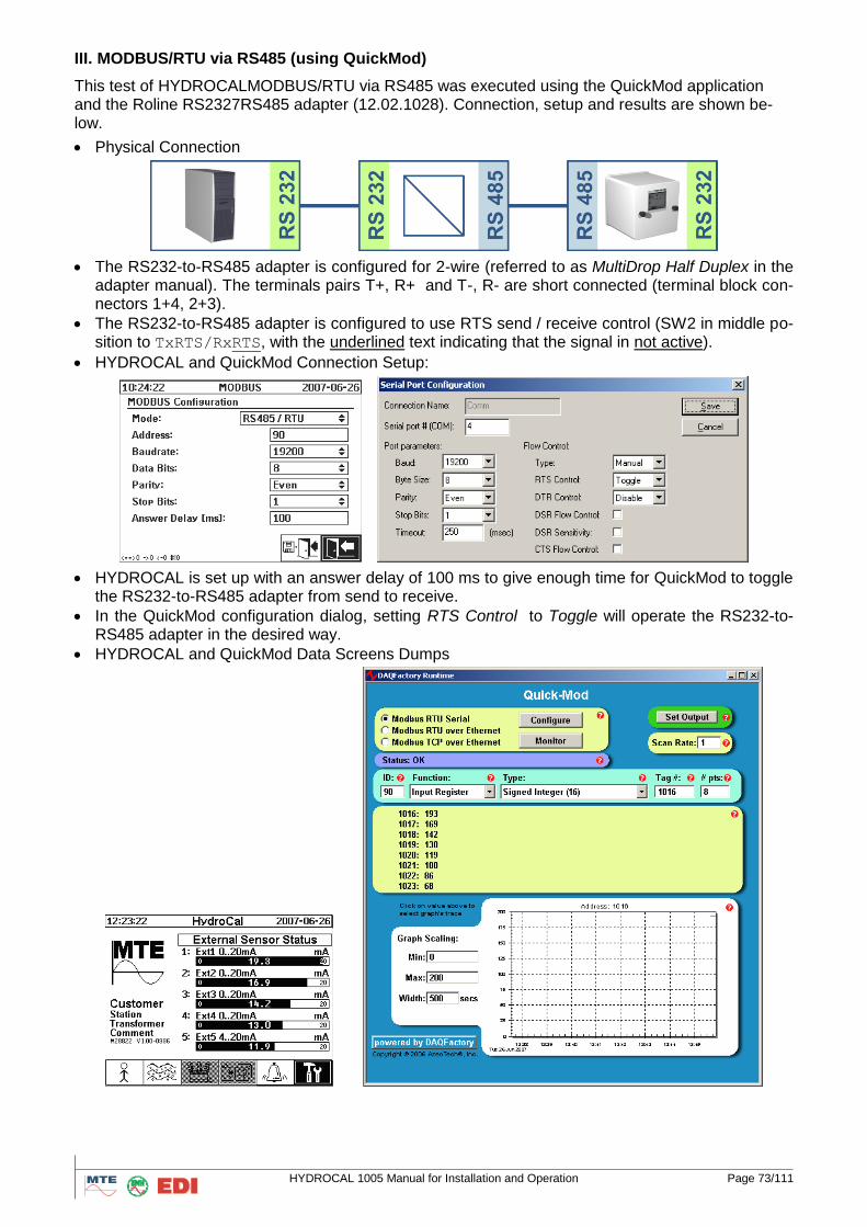
HYDROCAL 1005 Manual for Installation and Operation Page 73/111
III. MODBUS/RTU via RS485 (using QuickMod)
This test of HYDROCALMODBUS/RTU via RS485 was executed using the QuickMod application and the Roline RS2327RS485 adapter (12.02.1028). Connection, setup and results are shown be-low.
Physical Connection
The RS232-to-RS485 adapter is configured for 2-wire (referred to as MultiDrop Half Duplex in the adapter manual). The terminals pairs T+, R+ and T-, R- are short connected (terminal block con-nectors 1+4, 2+3).
The RS232-to-RS485 adapter is configured to use RTS send / receive control (SW2 in middle po-sition to TxRTS/RxRTS, with the underlined text indicating that the signal in not active).
HYDROCAL and QuickMod Connection Setup:
HYDROCAL is set up with an answer delay of 100 ms to give enough time for QuickMod to toggle the RS232-to-RS485 adapter from send to receive.
In the QuickMod configuration dialog, setting RTS Control to Toggle will operate the RS232-to-RS485 adapter in the desired way.
HYDROCAL and QuickMod Data Screens Dumps
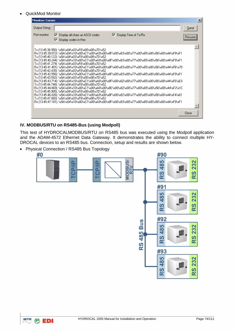
HYDROCAL 1005 Manual for Installation and Operation Page 74/111
QuickMod Monitor
IV. MODBUS/RTU on RS485-Bus (using Modpoll)
This test of HYDROCALMODBUS/RTU on RS485 bus was executed using the Modpoll application and the ADAM-4572 Ethernet Data Gateway. It demonstrates the ability to connect multiple HY-DROCAL devices to an RS485 bus. Connection, setup and results are shown below.
Physical Connection / RS485 Bus Topology
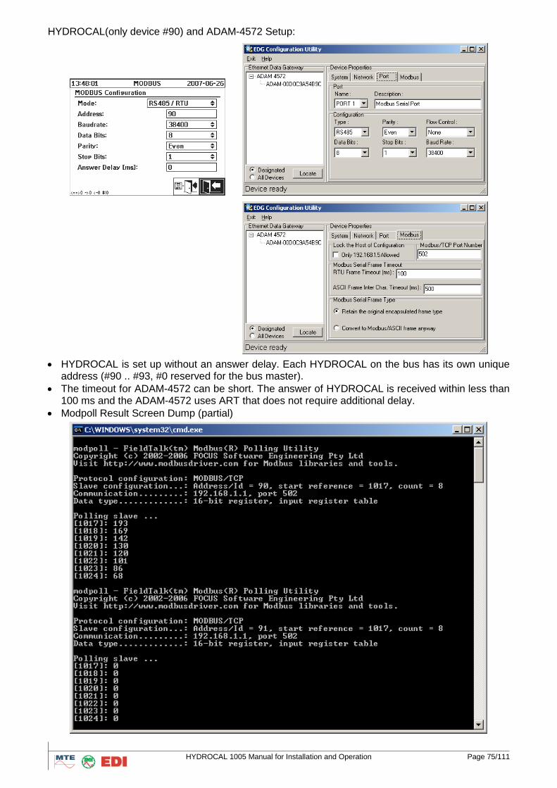
HYDROCAL 1005 Manual for Installation and Operation Page 75/111
HYDROCAL(only device #90) and ADAM-4572 Setup:
HYDROCAL is set up without an answer delay. Each HYDROCAL on the bus has its own unique address (#90 .. #93, #0 reserved for the bus master).
The timeout for ADAM-4572 can be short. The answer of HYDROCAL is received within less than 100 ms and the ADAM-4572 uses ART that does not require additional delay.
Modpoll Result Screen Dump (partial)

HYDROCAL 1005 Manual for Installation and Operation Page 76/111
5. Windows Software HydroSoft
5.1 Purpose of the program
HydroSoft is a program compatible with MS Windows for use with HYDROCAL1005 to provide a comprehensive transformer monitoring system. HydroSoft not only reads and processes the data of HYDROCAL1005 but can also used in the configuration of the HYDROCAL1005 unit. The program is compatible for use with operating systems MS XP with Service Pack 3 / Vista /Windows 7
.
HydroSoft offers the following functions:
Reading data from HYDROCAL1005 unit
Data processing
Export of data to other standard windows programs
Storage on data mediums, read from data medium, archiving of measuring data
Configuration of analogue inputs of HYDROCAL1005 unit
Configuration of alarms and respective alarm outputs of HYDROCAL1005
5.2 Remarks for use of this operation handbook
The following operation handbook explains in details the installation and operation of HydroSoft on your PC. It contains the following sections:
Program Installation and Start up
Program functions
General rules for use as transformer monitoring system
Export and storage of data
5.3 Requirements to the PC
The PC must fulfil the following requirements:
Pentium Processor clock 300MHz
Free disc space for installation on hard disk 20 MB, additional memory space for data storage
RAM memory 256MB
Operating system: XP with Service Pack 3 / Vista /Windows 7
CD-ROM drive
Interface RS232C / Ethernet
Signals used are RxD, TxD, GND
Serial interface cable 1:1
.NET Framework 1.1 redistributable must be supported
Microsoft Data Access Components 2.6 (MDAC) or new version must be supported
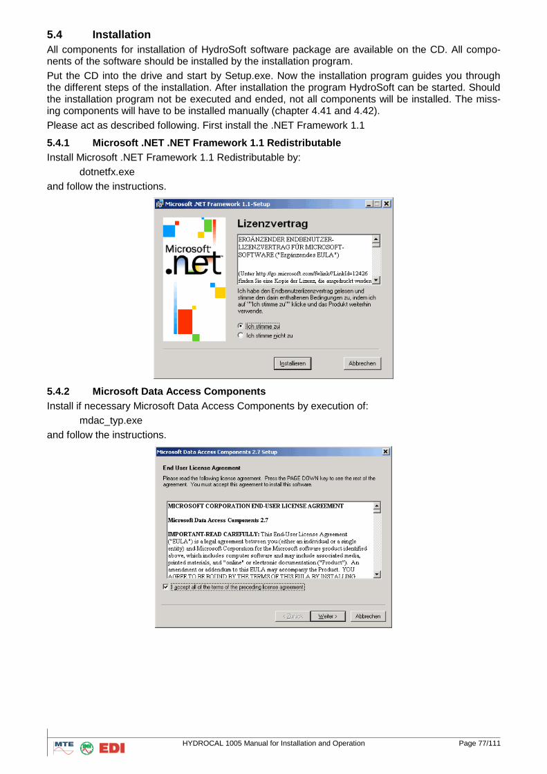
HYDROCAL 1005 Manual for Installation and Operation Page 77/111
5.4 Installation
All components for installation of HydroSoft software package are available on the CD. All compo-nents of the software should be installed by the installation program.
Put the CD into the drive and start by Setup.exe. Now the installation program guides you through the different steps of the installation. After installation the program HydroSoft can be started. Should the installation program not be executed and ended, not all components will be installed. The miss-ing components will have to be installed manually (chapter 4.41 and 4.42).
Please act as described following. First install the .NET Framework 1.1
5.4.1 Microsoft .NET .NET Framework 1.1 Redistributable
Install Microsoft .NET Framework 1.1 Redistributable by:
dotnetfx.exe
and follow the instructions.
5.4.2 Microsoft Data Access Components
Install if necessary Microsoft Data Access Components by execution of:
mdac_typ.exe
and follow the instructions.
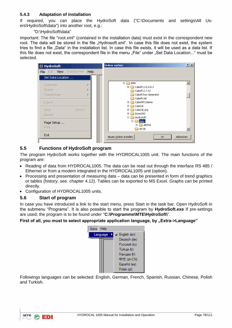
HYDROCAL 1005 Manual for Installation and Operation Page 78/111
5.4.3 Adaptation of installation
If required, you can place the HydroSoft data ("C:\Documents and settings\All Us-ers\HydroSoft\data") into another root, e.g.:
"D:\HydroSoft\data"
Important: The file "root.xml" (contained in the installation data) must exist in the correspondent new root. The data will be stored in the file „Hydrosoft.xml“. In case this file does not exist, the system tries to find a file „Data“ in the installation list. In case this file exists, it will be used as a data list. If this file does not exist, the correspondent file in the menu „File“ under „Set Data Location...“ must be selected.
5.5 Functions of HydroSoft program
The program HydroSoft works together with the HYDROCAL1005 unit. The main functions of the program are:
Reading of data from HYDROCAL1005. The data can be read out through the interface RS 485 / Ethernet or from a modem integrated in the HYDROCAL1005 unit (option).
Processing and presentation of measuring data – data can be presented in form of trend graphics or tables (history, see. chapter 4.12). Tables can be exported to MS Excel. Graphs can be printed directly.
Configuration of HYDROCAL1005 units.
5.6 Start of program
In case you have introduced a link to the start menu, press Start in the task bar. Open HydroSoft in
the submenu “Programs”. It is also possible to start the program by HydroSoft.exe If pre-settings
are used; the program is to be found under "C:\Programme\MTE\HydroSoft\“.
First of all, you must to select appropriate application language, by „Extra->Language”
Followings languages can be selected: English, German, French, Spanish, Russian, Chinese, Polish and Turkish.
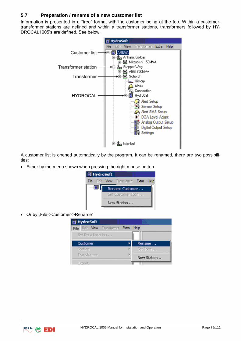
HYDROCAL 1005 Manual for Installation and Operation Page 79/111
5.7 Preparation / rename of a new customer list
Information is presented in a “tree” format with the customer being at the top. Within a customer, transformer stations are defined and within a transformer stations, transformers followed by HY-DROCAL1005’s are defined. See below.
A customer list is opened automatically by the program. It can be renamed, there are two possibili-ties:
Either by the menu shown when pressing the right mouse button
Or by „File->Customer->Rename“
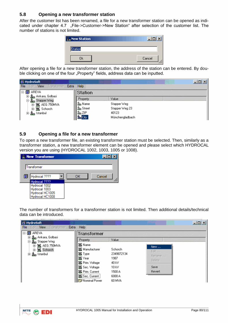
HYDROCAL 1005 Manual for Installation and Operation Page 80/111
5.8 Opening a new transformer station
After the customer list has been renamed, a file for a new transformer station can be opened as indi-cated under chapter 4.7 „File->Customer->New Station“ after selection of the customer list. The number of stations is not limited.
After opening a file for a new transformer station, the address of the station can be entered. By dou-ble clicking on one of the four „Property” fields, address data can be inputted.
5.9 Opening a file for a new transformer
To open a new transformer file, an existing transformer station must be selected. Then, similarly as a transformer station, a new transformer element can be opened and please select which HYDROCAL version you are using (HYDROCAL 1002, 1003, 1005 or 1008).
The number of transformers for a transformer station is not limited. Then additional details/technical data can be introduced.
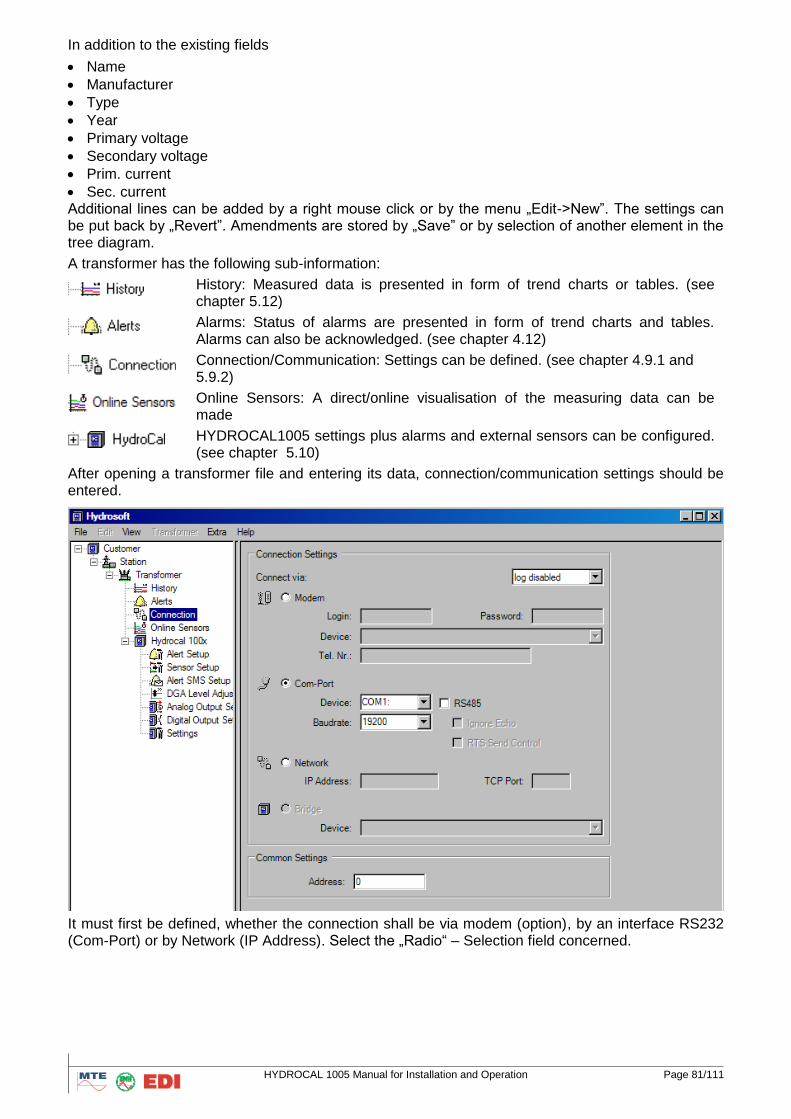
HYDROCAL 1005 Manual for Installation and Operation Page 81/111
In addition to the existing fields
Name
Manufacturer
Type
Year
Primary voltage
Secondary voltage
Prim. current
Sec. current Additional lines can be added by a right mouse click or by the menu „Edit->New”. The settings can be put back by „Revert”. Amendments are stored by „Save” or by selection of another element in the tree diagram.
A transformer has the following sub-information:
History: Measured data is presented in form of trend charts or tables. (see chapter 5.12)
Alarms: Status of alarms are presented in form of trend charts and tables. Alarms can also be acknowledged. (see chapter 4.12)
Connection/Communication: Settings can be defined. (see chapter 4.9.1 and 5.9.2)
Online Sensors: A direct/online visualisation of the measuring data can be made
HYDROCAL1005 settings plus alarms and external sensors can be configured. (see chapter 5.10)
After opening a transformer file and entering its data, connection/communication settings should be entered.
It must first be defined, whether the connection shall be via modem (option), by an interface RS232 (Com-Port) or by Network (IP Address). Select the „Radio“ – Selection field concerned.
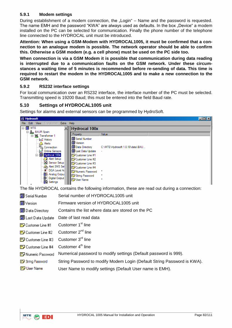
HYDROCAL 1005 Manual for Installation and Operation Page 82/111
5.9.1 Modem settings
During establishment of a modem connection, the „Login“ – Name and the password is requested. The name EMH and the password “KWA” are always used as defaults. In the box „Device“ a modem installed on the PC can be selected for communication. Finally the phone number of the telephone line connected to the HYDROCAL unit must be introduced.
Attention: When using a GSM-Modem with HYDROCAL1005, it must be confirmed that a con-
nection to an analogue modem is possible. The network operator should be able to confirm
this. Otherwise a GSM modem (e.g. a cell phone) must be used on the PC side too.
When connection is via a GSM Modem it is possible that communication during data reading
is interrupted due to a communication faults on the GSM network. Under these circum-
stances a waiting time of 5 minutes is recommended before re-sending of data. This time is
required to restart the modem in the HYDROCAL1005 and to make a new connection to the
GSM network.
5.9.2 RS232 interface settings
For local communication over an RS232 interface, the interface number of the PC must be selected. Transmitting speed is 19200 Baud; this must be entered into the field Baud rate.
5.10 Settings of HYDROCAL1005 unit
Settings for alarms and external sensors can be programmed by HydroSoft.
The file HYDROCAL contains the following information, these are read out during a connection:
Serial number of HYDROCAL1005 unit
Firmware version of HYDROCAL1005 unit
Contains the list where data are stored on the PC
Date of last read data
Customer 1st line
Customer 2nd
line
Customer 3rd line
Customer 4th line
Numerical password to modify settings (Default password is 999).
String Password to modify Modem Login (Default String Password is KWA).
User Name to modify settings (Default User name is EMH).
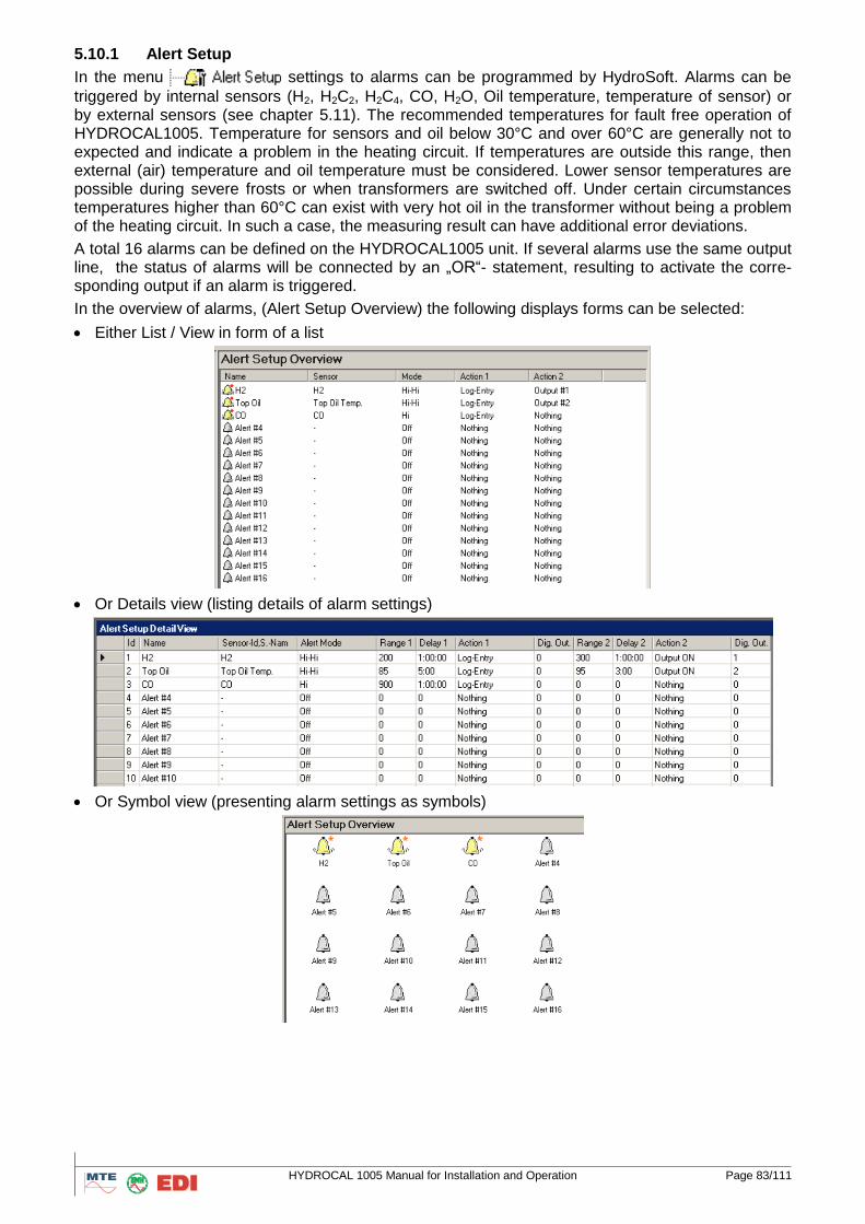
HYDROCAL 1005 Manual for Installation and Operation Page 83/111
5.10.1 Alert Setup
In the menu settings to alarms can be programmed by HydroSoft. Alarms can be
triggered by internal sensors (H2, H2C2, H2C4, CO, H2O, Oil temperature, temperature of sensor) or by external sensors (see chapter 5.11). The recommended temperatures for fault free operation of HYDROCAL1005. Temperature for sensors and oil below 30°C and over 60°C are generally not to expected and indicate a problem in the heating circuit. If temperatures are outside this range, then external (air) temperature and oil temperature must be considered. Lower sensor temperatures are possible during severe frosts or when transformers are switched off. Under certain circumstances temperatures higher than 60°C can exist with very hot oil in the transformer without being a problem of the heating circuit. In such a case, the measuring result can have additional error deviations.
A total 16 alarms can be defined on the HYDROCAL1005 unit. If several alarms use the same output line, the status of alarms will be connected by an „OR“- statement, resulting to activate the corre-sponding output if an alarm is triggered.
In the overview of alarms, (Alert Setup Overview) the following displays forms can be selected:
Either List / View in form of a list
Or Details view (listing details of alarm settings)
Or Symbol view (presenting alarm settings as symbols)
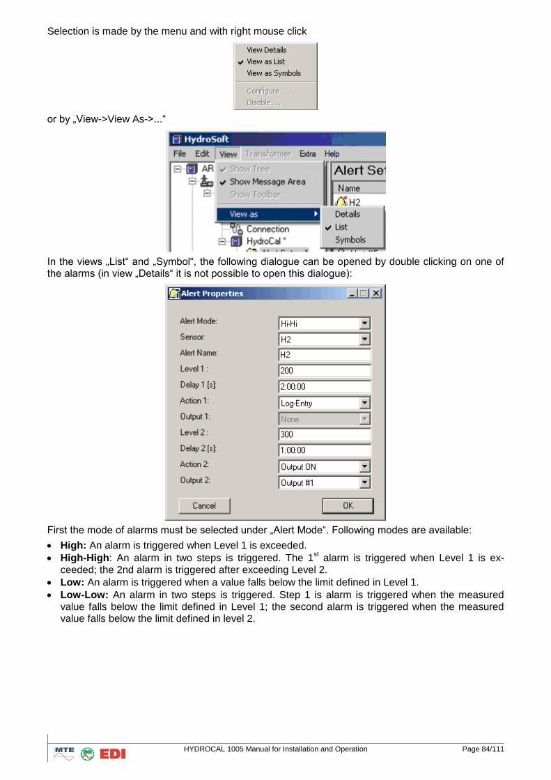
HYDROCAL 1005 Manual for Installation and Operation Page 84/111
Selection is made by the menu and with right mouse click
or by „View->View As->...“
In the views „List“ and „Symbol“, the following dialogue can be opened by double clicking on one of the alarms (in view „Details“ it is not possible to open this dialogue):
First the mode of alarms must be selected under „Alert Mode“. Following modes are available:
High: An alarm is triggered when Level 1 is exceeded.
High-High: An alarm in two steps is triggered. The 1st alarm is triggered when Level 1 is ex-
ceeded; the 2nd alarm is triggered after exceeding Level 2.
Low: An alarm is triggered when a value falls below the limit defined in Level 1.
Low-Low: An alarm in two steps is triggered. Step 1 is alarm is triggered when the measured value falls below the limit defined in Level 1; the second alarm is triggered when the measured value falls below the limit defined in level 2.
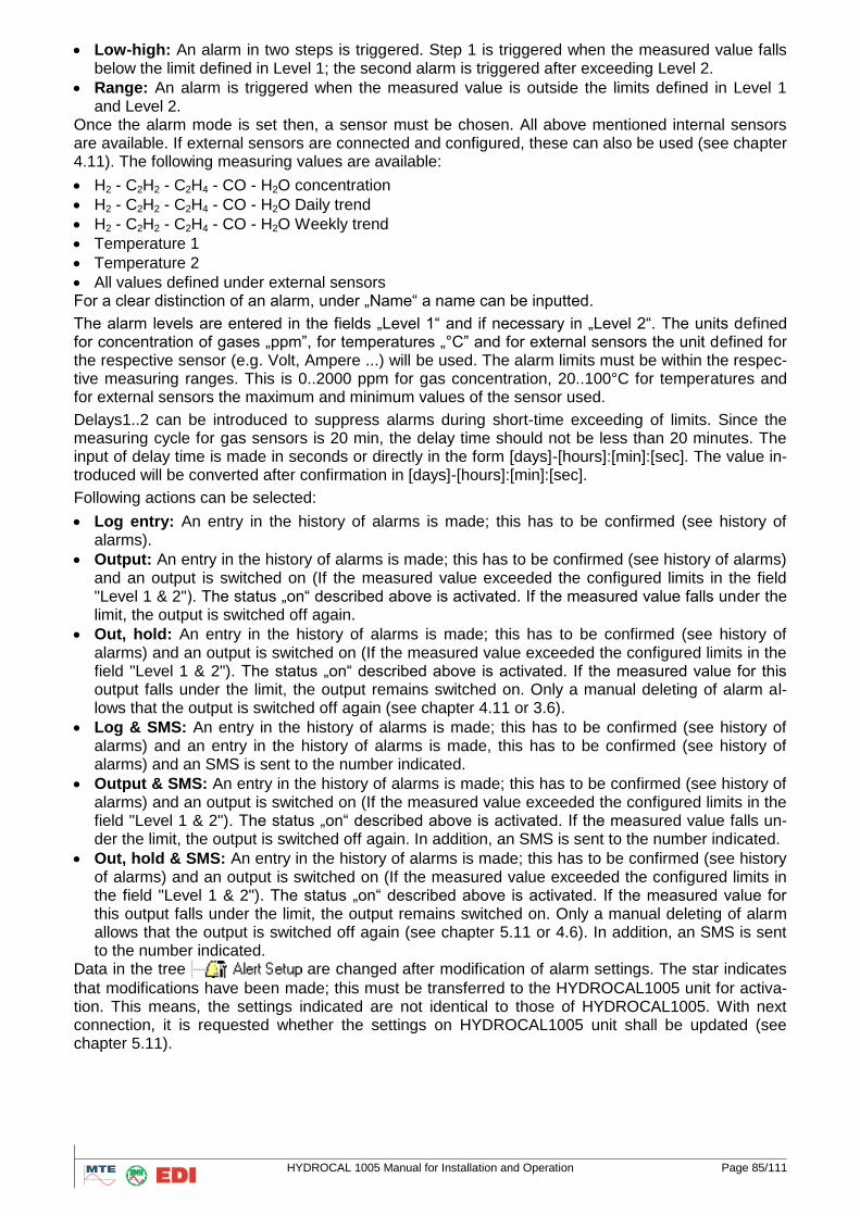
HYDROCAL 1005 Manual for Installation and Operation Page 85/111
Low-high: An alarm in two steps is triggered. Step 1 is triggered when the measured value falls below the limit defined in Level 1; the second alarm is triggered after exceeding Level 2.
Range: An alarm is triggered when the measured value is outside the limits defined in Level 1 and Level 2.
Once the alarm mode is set then, a sensor must be chosen. All above mentioned internal sensors are available. If external sensors are connected and configured, these can also be used (see chapter 4.11). The following measuring values are available:
H2 - C2H2 - C2H4 - CO - H2O concentration
H2 - C2H2 - C2H4 - CO - H2O Daily trend
H2 - C2H2 - C2H4 - CO - H2O Weekly trend
Temperature 1
Temperature 2
All values defined under external sensors For a clear distinction of an alarm, under „Name“ a name can be inputted.
The alarm levels are entered in the fields „Level 1“ and if necessary in „Level 2“. The units defined for concentration of gases „ppm”, for temperatures „°C” and for external sensors the unit defined for the respective sensor (e.g. Volt, Ampere ...) will be used. The alarm limits must be within the respec-tive measuring ranges. This is 0..2000 ppm for gas concentration, 20..100°C for temperatures and for external sensors the maximum and minimum values of the sensor used.
Delays1..2 can be introduced to suppress alarms during short-time exceeding of limits. Since the measuring cycle for gas sensors is 20 min, the delay time should not be less than 20 minutes. The input of delay time is made in seconds or directly in the form [days]-[hours]:[min]:[sec]. The value in-troduced will be converted after confirmation in [days]-[hours]:[min]:[sec].
Following actions can be selected:
Log entry: An entry in the history of alarms is made; this has to be confirmed (see history of alarms).
Output: An entry in the history of alarms is made; this has to be confirmed (see history of alarms) and an output is switched on (If the measured value exceeded the configured limits in the field "Level 1 & 2"). The status „on“ described above is activated. If the measured value falls under the limit, the output is switched off again.
Out, hold: An entry in the history of alarms is made; this has to be confirmed (see history of alarms) and an output is switched on (If the measured value exceeded the configured limits in the field "Level 1 & 2"). The status „on“ described above is activated. If the measured value for this output falls under the limit, the output remains switched on. Only a manual deleting of alarm al-lows that the output is switched off again (see chapter 4.11 or 3.6).
Log & SMS: An entry in the history of alarms is made; this has to be confirmed (see history of alarms) and an entry in the history of alarms is made, this has to be confirmed (see history of alarms) and an SMS is sent to the number indicated.
Output & SMS: An entry in the history of alarms is made; this has to be confirmed (see history of alarms) and an output is switched on (If the measured value exceeded the configured limits in the field "Level 1 & 2"). The status „on“ described above is activated. If the measured value falls un-der the limit, the output is switched off again. In addition, an SMS is sent to the number indicated.
Out, hold & SMS: An entry in the history of alarms is made; this has to be confirmed (see history of alarms) and an output is switched on (If the measured value exceeded the configured limits in the field "Level 1 & 2"). The status „on“ described above is activated. If the measured value for this output falls under the limit, the output remains switched on. Only a manual deleting of alarm allows that the output is switched off again (see chapter 5.11 or 4.6). In addition, an SMS is sent to the number indicated.
Data in the tree are changed after modification of alarm settings. The star indicates
that modifications have been made; this must be transferred to the HYDROCAL1005 unit for activa-tion. This means, the settings indicated are not identical to those of HYDROCAL1005. With next connection, it is requested whether the settings on HYDROCAL1005 unit shall be updated (see chapter 5.11).
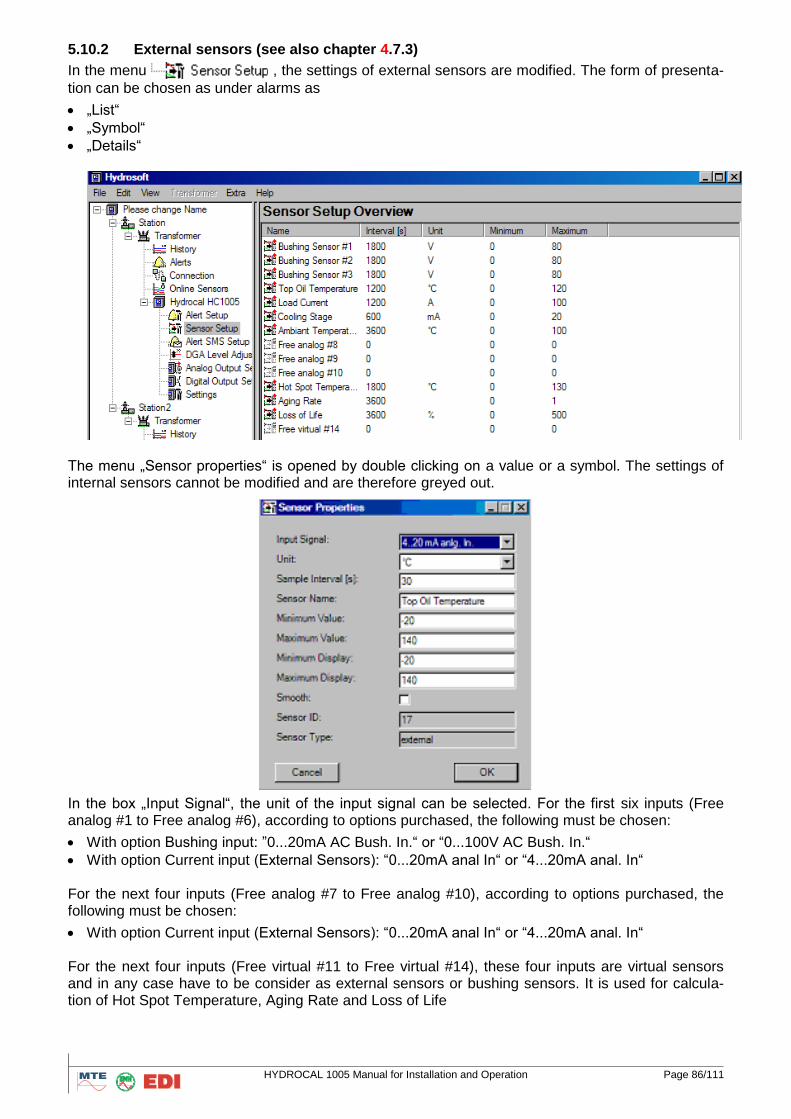
HYDROCAL 1005 Manual for Installation and Operation Page 86/111
5.10.2 External sensors (see also chapter 4.7.3)
In the menu , the settings of external sensors are modified. The form of presenta-
tion can be chosen as under alarms as
„List“
„Symbol“
„Details“
The menu „Sensor properties“ is opened by double clicking on a value or a symbol. The settings of internal sensors cannot be modified and are therefore greyed out.
In the box „Input Signal“, the unit of the input signal can be selected. For the first six inputs (Free analog #1 to Free analog #6), according to options purchased, the following must be chosen:
With option Bushing input: ”0...20mA AC Bush. In.“ or “0...100V AC Bush. In.“
With option Current input (External Sensors): “0...20mA anal In“ or “4...20mA anal. In“ For the next four inputs (Free analog #7 to Free analog #10), according to options purchased, the following must be chosen:
With option Current input (External Sensors): “0...20mA anal In“ or “4...20mA anal. In“ For the next four inputs (Free virtual #11 to Free virtual #14), these four inputs are virtual sensors and in any case have to be consider as external sensors or bushing sensors. It is used for calcula-tion of Hot Spot Temperature, Aging Rate and Loss of Life
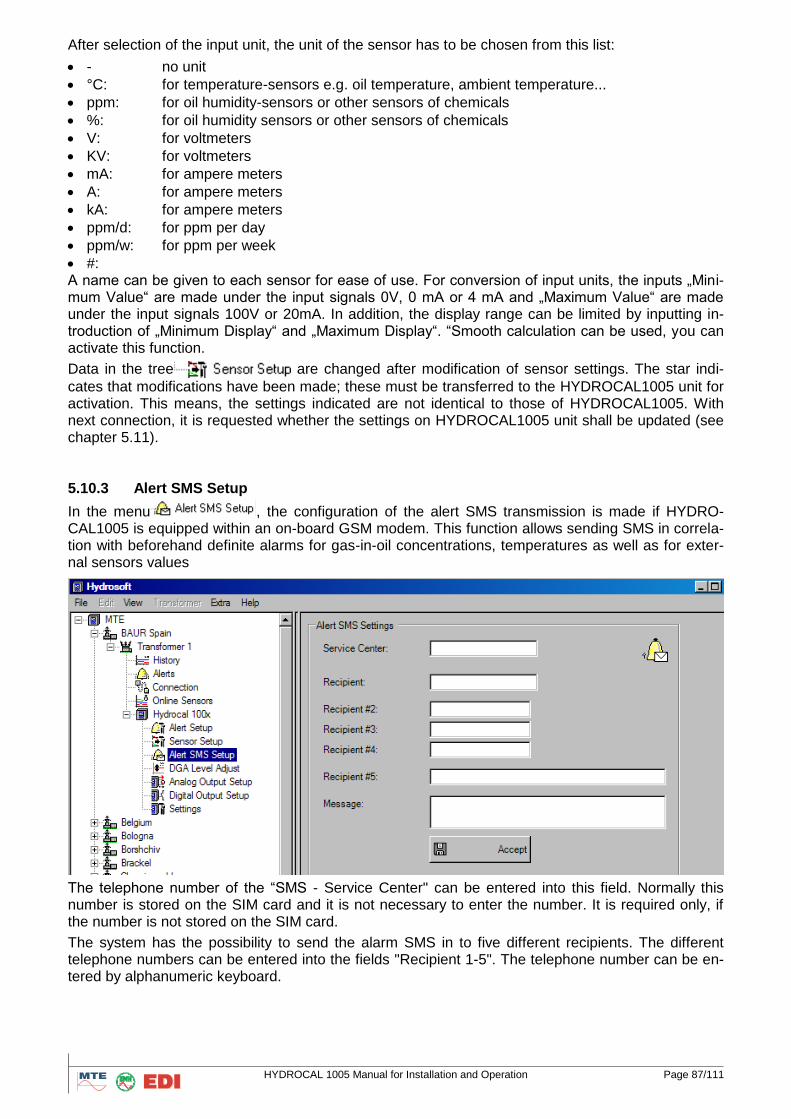
HYDROCAL 1005 Manual for Installation and Operation Page 87/111
After selection of the input unit, the unit of the sensor has to be chosen from this list:
- no unit
°C: for temperature-sensors e.g. oil temperature, ambient temperature...
ppm: for oil humidity-sensors or other sensors of chemicals
%: for oil humidity sensors or other sensors of chemicals
V: for voltmeters
KV: for voltmeters
mA: for ampere meters
A: for ampere meters
kA: for ampere meters
ppm/d: for ppm per day
ppm/w: for ppm per week
#: A name can be given to each sensor for ease of use. For conversion of input units, the inputs „Mini-mum Value“ are made under the input signals 0V, 0 mA or 4 mA and „Maximum Value“ are made under the input signals 100V or 20mA. In addition, the display range can be limited by inputting in-troduction of „Minimum Display“ and „Maximum Display“. “Smooth calculation can be used, you can activate this function.
Data in the tree are changed after modification of sensor settings. The star indi-
cates that modifications have been made; these must be transferred to the HYDROCAL1005 unit for activation. This means, the settings indicated are not identical to those of HYDROCAL1005. With next connection, it is requested whether the settings on HYDROCAL1005 unit shall be updated (see chapter 5.11).
5.10.3 Alert SMS Setup
In the menu , the configuration of the alert SMS transmission is made if HYDRO-CAL1005 is equipped within an on-board GSM modem. This function allows sending SMS in correla-tion with beforehand definite alarms for gas-in-oil concentrations, temperatures as well as for exter-nal sensors values
The telephone number of the “SMS - Service Center" can be entered into this field. Normally this number is stored on the SIM card and it is not necessary to enter the number. It is required only, if the number is not stored on the SIM card.
The system has the possibility to send the alarm SMS in to five different recipients. The different telephone numbers can be entered into the fields "Recipient 1-5". The telephone number can be en-tered by alphanumeric keyboard.
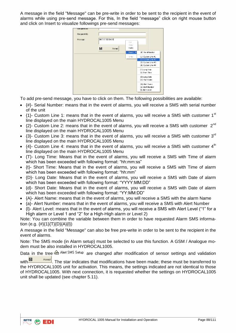
HYDROCAL 1005 Manual for Installation and Operation Page 88/111
A message in the field "Message" can be pre-write in order to be sent to the recipient in the event of alarms while using pre-send message. For this, In the field “message” click on right mouse button and click on Insert to visualize followings pre-send messages:
To add pre-send message, you have to click on them. The following possibilities are available:
{#}- Serial Number: means that in the event of alarms, you will receive a SMS with serial number of the unit
{1}- Custom Line 1: means that in the event of alarms, you will receive a SMS with customer 1st
line displayed on the main HYDROCAL1005 Menu
{2}- Custom Line 2: means that in the event of alarms, you will receive a SMS with customer 2nd
line displayed on the main HYDROCAL1005 Menu
{3}- Custom Line 3: means that in the event of alarms, you will receive a SMS with customer 3rd
line displayed on the main HYDROCAL1005 Menu
{4}- Custom Line 4: means that in the event of alarms, you will receive a SMS with customer 4th
line displayed on the main HYDROCAL1005 Menu
{T}- Long Time: Means that in the event of alarms, you will receive a SMS with Time of alarm which has been exceeded with following format: “hh:mm:ss”
{t}- Short Time: Means that in the event of alarms, you will receive a SMS with Time of alarm which has been exceeded with following format: “hh:mm”
{D}- Long Date: Means that in the event of alarms, you will receive a SMS with Date of alarm which has been exceeded with following format: “YYYY:MM:DD”
{d}- Short Date: Means that in the event of alarms, you will receive a SMS with Date of alarm which has been exceeded with following format: “YY:MM:DD”
{A}- Alert Name: means that in the event of alarms, you will receive a SMS with the alarm Name
{a}- Alert Number: means that in the event of alarms, you will receive a SMS with Alert Number
{l}- Alert Level: means that in the event of alarms, you will receive a SMS with Alert Level (“1” for a High alarm or Level 1 and “2” for a High-High alarm or Level 2)
Note: You can combine the variable between them in order to have requested Alarm SMS informa-tion (e.g. {#}{1}{T}{D}{A}{l})
A message in the field "Message" can also be free pre-write in order to be sent to the recipient in the event of alarms.
Note: The SMS mode (in Alarm setup) must be selected to use this function. A GSM / Analogue mo-dem must be also installed in HYDROCAL1005.
Data in the tree are changed after modification of sensor settings and validation
with . The star indicates that modifications have been made; these must be transferred to the HYDROCAL1005 unit for activation. This means, the settings indicated are not identical to those of HYDROCAL1005. With next connection, it is requested whether the settings on HYDROCAL1005 unit shall be updated (see chapter 5.11).
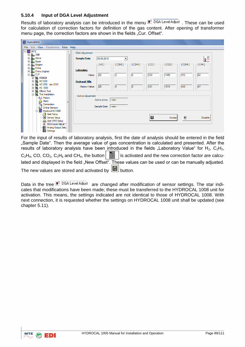
HYDROCAL 1005 Manual for Installation and Operation Page 89/111
5.10.4 Input of DGA Level Adjustment
Results of laboratory analysis can be introduced in the menu . These can be used for calculation of correction factors for definition of the gas content. After opening of transformer menu page, the correction factors are shown in the fields „Cur. Offset“.
For the input of results of laboratory analysis, first the date of analysis should be entered in the field „Sample Date“. Then the average value of gas concentration is calculated and presented. After the results of laboratory analysis have been introduced in the fields „Laboratory Value“ for H2, C2H2,
C2H4, CO, CO2, C2H6 and CH4, the button is activated and the new correction factor are calcu-
lated and displayed in the field „New Offset“. These values can be used or can be manually adjusted.
The new values are stored and activated by button.
Data in the tree are changed after modification of sensor settings. The star indi-cates that modifications have been made; these must be transferred to the HYDROCAL 1008 unit for activation. This means, the settings indicated are not identical to those of HYDROCAL 1008. With next connection, it is requested whether the settings on HYDROCAL 1008 unit shall be updated (see chapter 5.11).
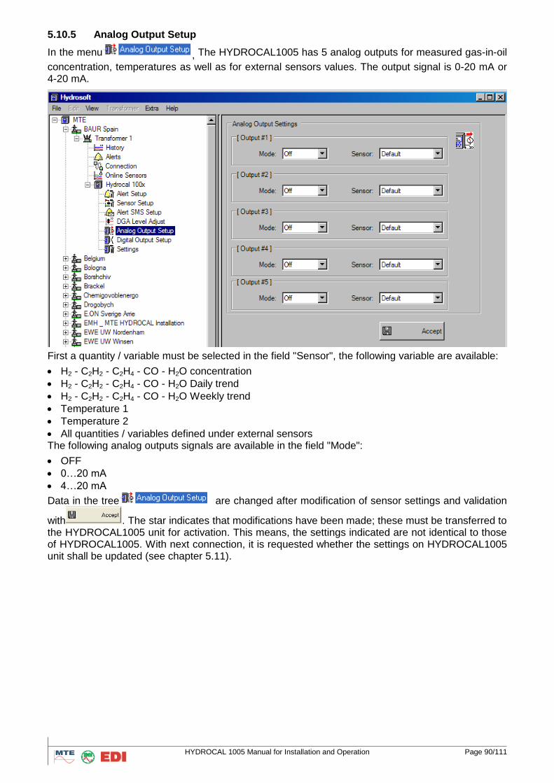
HYDROCAL 1005 Manual for Installation and Operation Page 90/111
5.10.5 Analog Output Setup
In the menu , The HYDROCAL1005 has 5 analog outputs for measured gas-in-oil
concentration, temperatures as well as for external sensors values. The output signal is 0-20 mA or 4-20 mA.
First a quantity / variable must be selected in the field "Sensor", the following variable are available:
H2 - C2H2 - C2H4 - CO - H2O concentration
H2 - C2H2 - C2H4 - CO - H2O Daily trend
H2 - C2H2 - C2H4 - CO - H2O Weekly trend
Temperature 1
Temperature 2
All quantities / variables defined under external sensors The following analog outputs signals are available in the field "Mode":
OFF
0…20 mA
4…20 mA
Data in the tree are changed after modification of sensor settings and validation
with . The star indicates that modifications have been made; these must be transferred to the HYDROCAL1005 unit for activation. This means, the settings indicated are not identical to those of HYDROCAL1005. With next connection, it is requested whether the settings on HYDROCAL1005 unit shall be updated (see chapter 5.11).
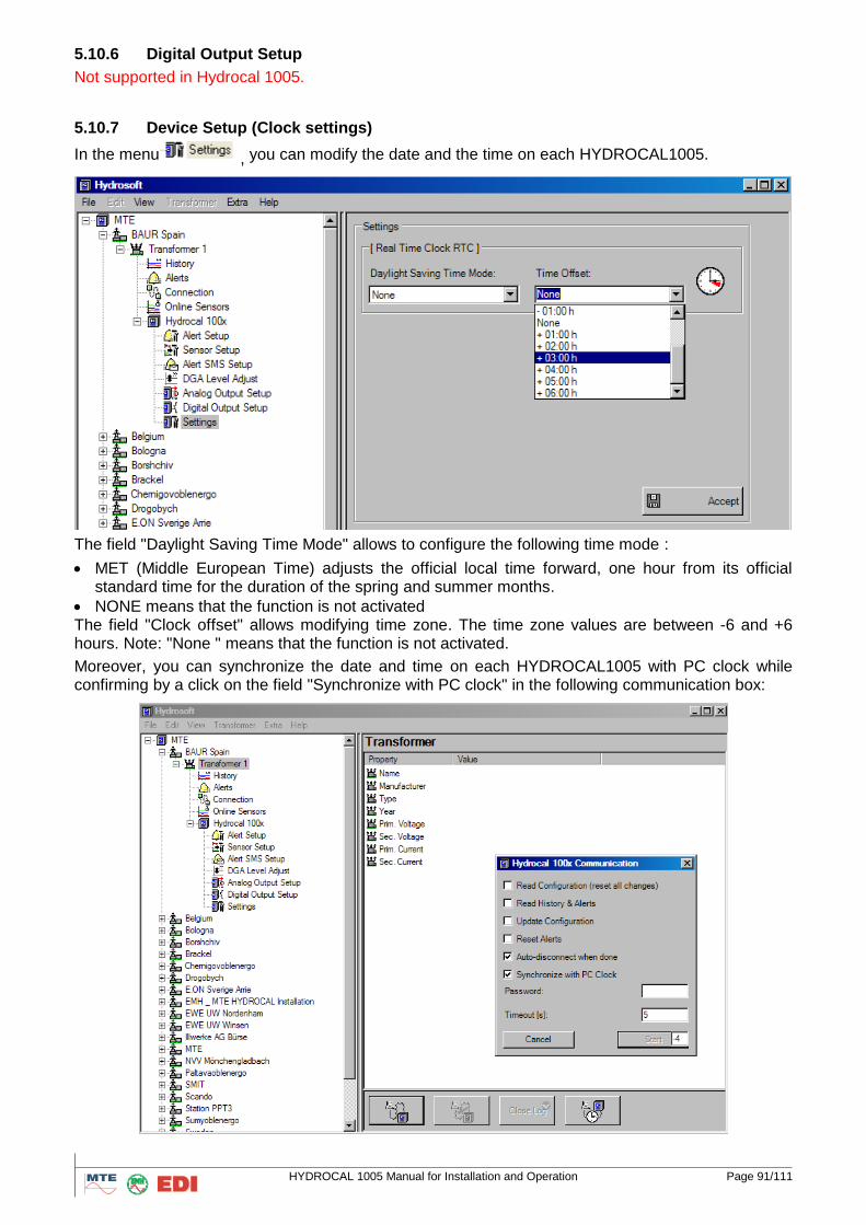
HYDROCAL 1005 Manual for Installation and Operation Page 91/111
5.10.6 Digital Output Setup
Not supported in Hydrocal 1005.
5.10.7 Device Setup (Clock settings)
In the menu , you can modify the date and the time on each HYDROCAL1005.
The field "Daylight Saving Time Mode" allows to configure the following time mode :
MET (Middle European Time) adjusts the official local time forward, one hour from its official standard time for the duration of the spring and summer months.
NONE means that the function is not activated The field "Clock offset" allows modifying time zone. The time zone values are between -6 and +6 hours. Note: "None " means that the function is not activated.
Moreover, you can synchronize the date and time on each HYDROCAL1005 with PC clock while confirming by a click on the field "Synchronize with PC clock" in the following communication box:
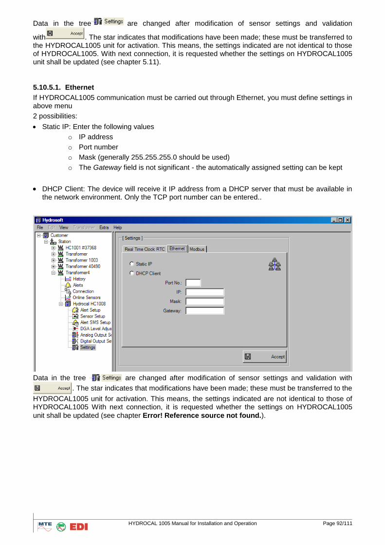
HYDROCAL 1005 Manual for Installation and Operation Page 92/111
Data in the tree are changed after modification of sensor settings and validation
with . The star indicates that modifications have been made; these must be transferred to the HYDROCAL1005 unit for activation. This means, the settings indicated are not identical to those of HYDROCAL1005. With next connection, it is requested whether the settings on HYDROCAL1005 unit shall be updated (see chapter 5.11).
5.10.5.1. Ethernet
If HYDROCAL1005 communication must be carried out through Ethernet, you must define settings in above menu
2 possibilities:
Static IP: Enter the following values
o IP address
o Port number
o Mask (generally 255.255.255.0 should be used)
o The Gateway field is not significant - the automatically assigned setting can be kept
DHCP Client: The device will receive it IP address from a DHCP server that must be available in the network environment. Only the TCP port number can be entered..
Data in the tree are changed after modification of sensor settings and validation with
. The star indicates that modifications have been made; these must be transferred to the
HYDROCAL1005 unit for activation. This means, the settings indicated are not identical to those of HYDROCAL1005 With next connection, it is requested whether the settings on HYDROCAL1005
unit shall be updated (see chapter Error! Reference source not found.).
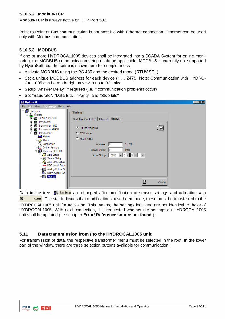
HYDROCAL 1005 Manual for Installation and Operation Page 93/111
5.10.5.2. Modbus-TCP
Modbus-TCP is always active on TCP Port 502.
Point-to-Point or Bus communication is not possible with Ethernet connection. Ethernet can be used only with Modbus communication.
5.10.5.3. MODBUS
If one or more HYDROCAL1005 devices shall be integrated into a SCADA System for online moni-toring, the MODBUS communication setup might be applicable. MODBUS is currently not supported by HydroSoft, but the setup is shown here for completeness
Activate MODBUS using the RS 485 and the desired mode (RTU/ASCII)
Set a unique MODBUS address for each device (1 … 247). Note: Communication with HYDRO-CAL1005 can be made right now with up to 32 units
Setup "Answer Delay" if required (i.e. if communication problems occur)
Set "Baudrate", "Data Bits", "Parity" and "Stop bits"
Data in the tree are changed after modification of sensor settings and validation with
. The star indicates that modifications have been made; these must be transferred to the
HYDROCAL1005 unit for activation. This means, the settings indicated are not identical to those of HYDROCAL1005. With next connection, it is requested whether the settings on HYDROCAL1005
unit shall be updated (see chapter Error! Reference source not found.).
5.11 Data transmission from / to the HYDROCAL1005 unit
For transmission of data, the respective transformer menu must be selected in the root. In the lower part of the window, there are three selection buttons available for communication.
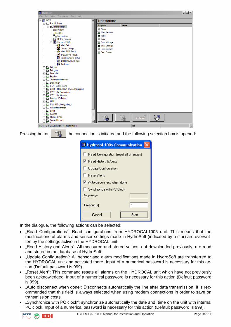
HYDROCAL 1005 Manual for Installation and Operation Page 94/111
Pressing button the connection is initiated and the following selection box is opened:
In the dialogue, the following actions can be selected:
„Read Configurations“: Read configurations from HYDROCAL1005 unit. This means that the modifications of alarms and sensor settings made in HydroSoft (indicated by a star) are overwrit-ten by the settings active in the HYDROCAL unit.
„Read History and Alerts“: All measured and stored values, not downloaded previously, are read and stored in the database of HydroSoft.
„Update Configuration“: All sensor and alarm modifications made in HydroSoft are transferred to the HYDROCAL unit and activated there. Input of a numerical password is necessary for this ac-tion (Default password is 999).
„Reset Alert“: This command resets all alarms on the HYDROCAL unit which have not previously been acknowledged. Input of a numerical password is necessary for this action (Default password is 999).
„Auto disconnect when done“: Disconnects automatically the line after data transmission. It is rec-ommended that this field is always selected when using modem connections in order to save on transmission costs.
„Synchronize with PC clock“: synchronize automatically the date and time on the unit with internal PC clock. Input of a numerical password is necessary for this action (Default password is 999).
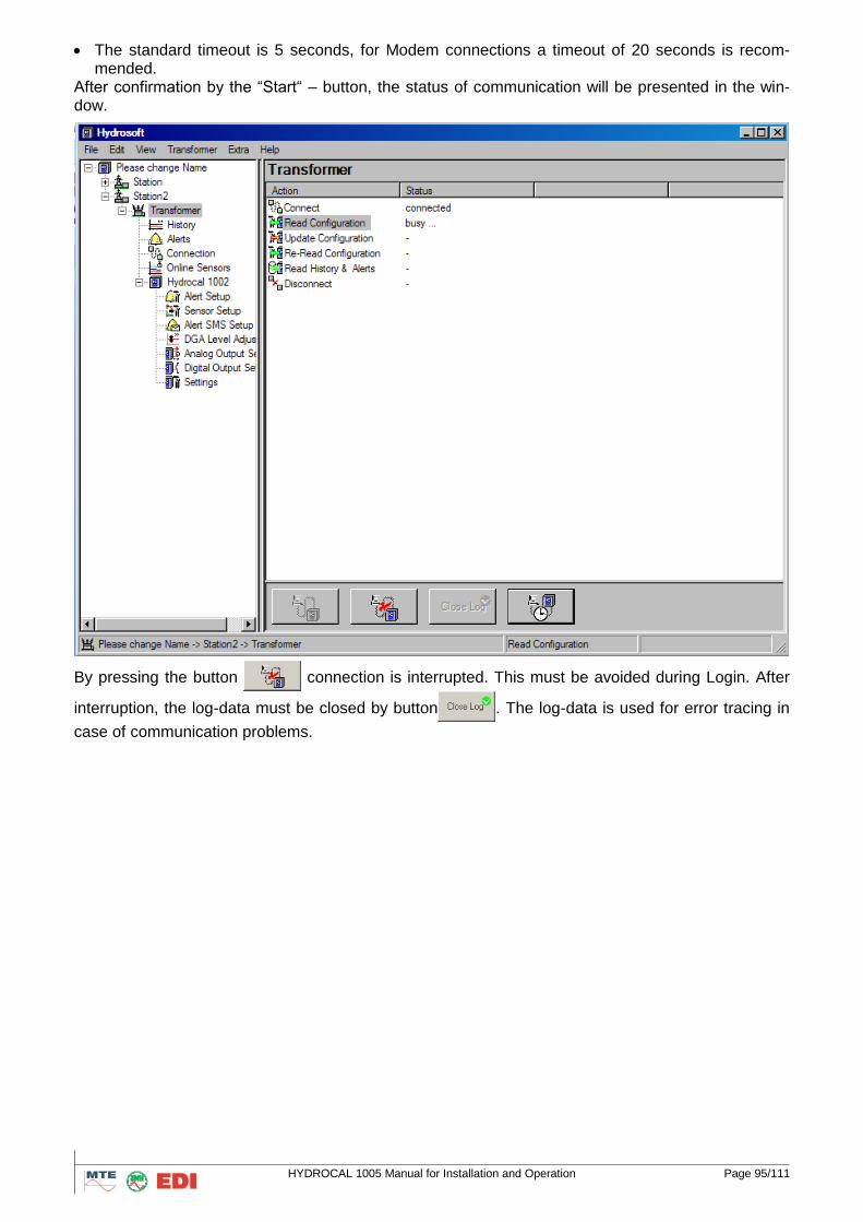
HYDROCAL 1005 Manual for Installation and Operation Page 95/111
The standard timeout is 5 seconds, for Modem connections a timeout of 20 seconds is recom-mended.
After confirmation by the “Start“ – button, the status of communication will be presented in the win-dow.
By pressing the button connection is interrupted. This must be avoided during Login. After
interruption, the log-data must be closed by button . The log-data is used for error tracing in
case of communication problems.
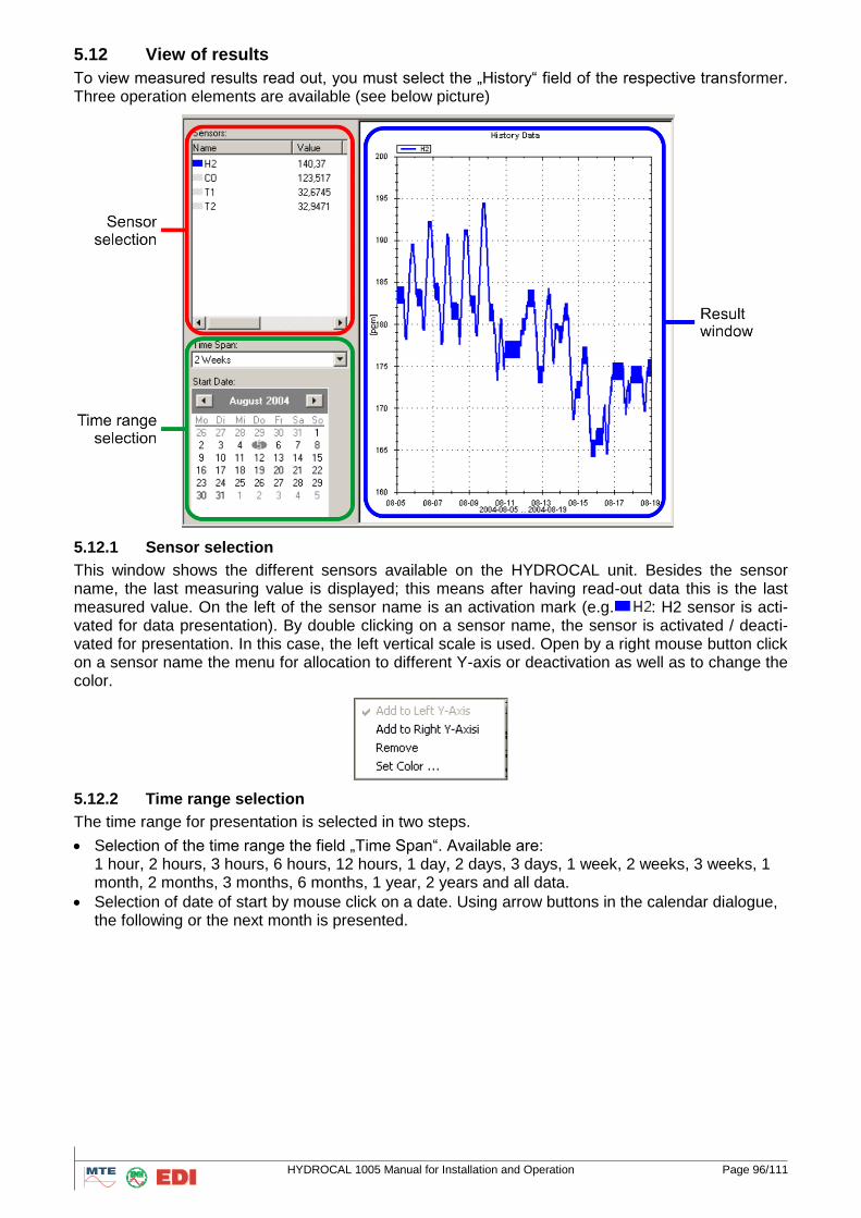
HYDROCAL 1005 Manual for Installation and Operation Page 96/111
5.12 View of results
To view measured results read out, you must select the „History“ field of the respective transformer. Three operation elements are available (see below picture)
5.12.1 Sensor selection
This window shows the different sensors available on the HYDROCAL unit. Besides the sensor name, the last measuring value is displayed; this means after having read-out data this is the last measured value. On the left of the sensor name is an activation mark (e.g. : H2 sensor is acti-vated for data presentation). By double clicking on a sensor name, the sensor is activated / deacti-vated for presentation. In this case, the left vertical scale is used. Open by a right mouse button click on a sensor name the menu for allocation to different Y-axis or deactivation as well as to change the color.
5.12.2 Time range selection
The time range for presentation is selected in two steps.
Selection of the time range the field „Time Span“. Available are: 1 hour, 2 hours, 3 hours, 6 hours, 12 hours, 1 day, 2 days, 3 days, 1 week, 2 weeks, 3 weeks, 1 month, 2 months, 3 months, 6 months, 1 year, 2 years and all data.
Selection of date of start by mouse click on a date. Using arrow buttons in the calendar dialogue, the following or the next month is presented.
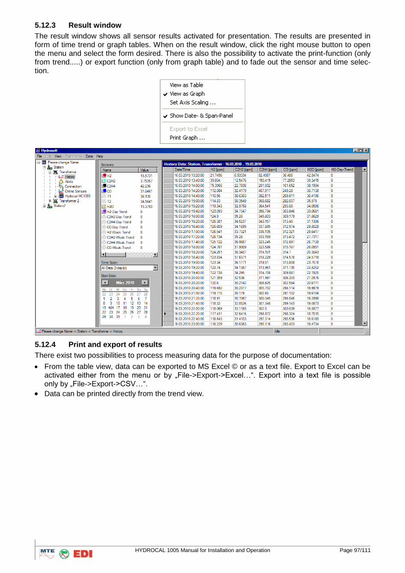
HYDROCAL 1005 Manual for Installation and Operation Page 97/111
5.12.3 Result window
The result window shows all sensor results activated for presentation. The results are presented in form of time trend or graph tables. When on the result window, click the right mouse button to open the menu and select the form desired. There is also the possibility to activate the print-function (only from trend.....) or export function (only from graph table) and to fade out the sensor and time selec-tion.
5.12.4 Print and export of results
There exist two possibilities to process measuring data for the purpose of documentation:
From the table view, data can be exported to MS Excel © or as a text file. Export to Excel can be activated either from the menu or by „File->Export->Excel…“. Export into a text file is possible only by „File->Export->CSV…“.
Data can be printed directly from the trend view.
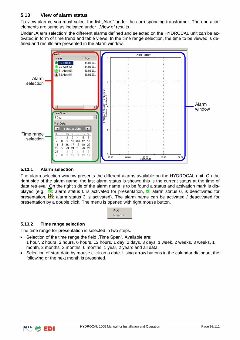
HYDROCAL 1005 Manual for Installation and Operation Page 98/111
5.13 View of alarm status
To view alarms, you must select the list „Alert“ under the corresponding transformer. The operation elements are same as indicated under „View of results.
Under „Alarm selection“ the different alarms defined and selected on the HYDROCAL unit can be ac-tivated in form of time trend and table views. In the time range selection, the time to be viewed is de-fined and results are presented in the alarm window.
5.13.1 Alarm selection
The alarm selection window presents the different alarms available on the HYDROCAL unit. On the right side of the alarm name, the last alarm status is shown; this is the current status at the time of data retrieval. On the right side of the alarm name is to be found a status and activation mark is dis-
played (e.g. : : alarm status 0 is activated for presentation, : alarm status 0, is deactivated for
presentation, : alarm status 3 is activated). The alarm name can be activated / deactivated for presentation by a double click. The menu is opened with right mouse button.
5.13.2 Time range selection
The time range for presentation is selected in two steps.
Selection of the time range the field „Time Span“. Available are: 1 hour, 2 hours, 3 hours, 6 hours, 12 hours, 1 day, 2 days, 3 days, 1 week, 2 weeks, 3 weeks, 1 month, 2 months, 3 months, 6 months, 1 year, 2 years and all data.
Selection of start date by mouse click on a date. Using arrow buttons in the calendar dialogue, the following or the next month is presented.
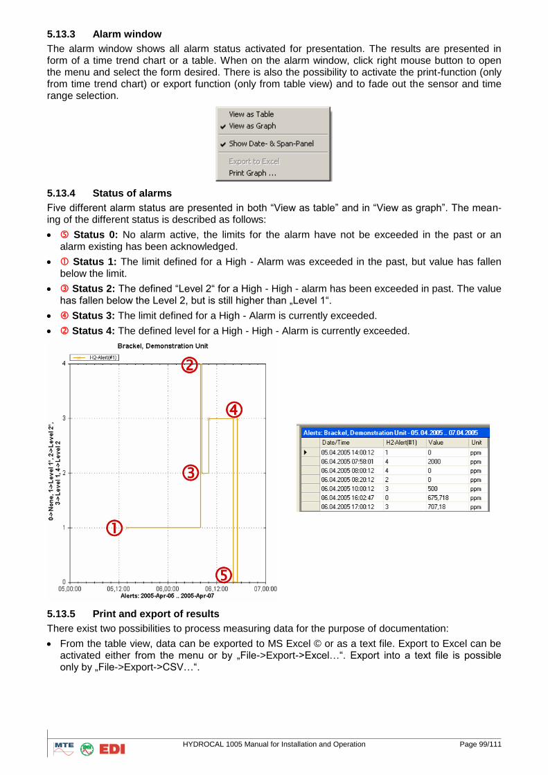
HYDROCAL 1005 Manual for Installation and Operation Page 99/111
5.13.3 Alarm window
The alarm window shows all alarm status activated for presentation. The results are presented in form of a time trend chart or a table. When on the alarm window, click right mouse button to open the menu and select the form desired. There is also the possibility to activate the print-function (only from time trend chart) or export function (only from table view) and to fade out the sensor and time range selection.
5.13.4 Status of alarms
Five different alarm status are presented in both “View as table” and in “View as graph”. The mean-ing of the different status is described as follows:
Status 0: No alarm active, the limits for the alarm have not be exceeded in the past or an alarm existing has been acknowledged.
Status 1: The limit defined for a High - Alarm was exceeded in the past, but value has fallen below the limit.
Status 2: The defined “Level 2“ for a High - High - alarm has been exceeded in past. The value has fallen below the Level 2, but is still higher than „Level 1“.
Status 3: The limit defined for a High - Alarm is currently exceeded.
Status 4: The defined level for a High - High - Alarm is currently exceeded.
5.13.5 Print and export of results
There exist two possibilities to process measuring data for the purpose of documentation:
From the table view, data can be exported to MS Excel © or as a text file. Export to Excel can be activated either from the menu or by „File->Export->Excel…“. Export into a text file is possible only by „File->Export->CSV…“.
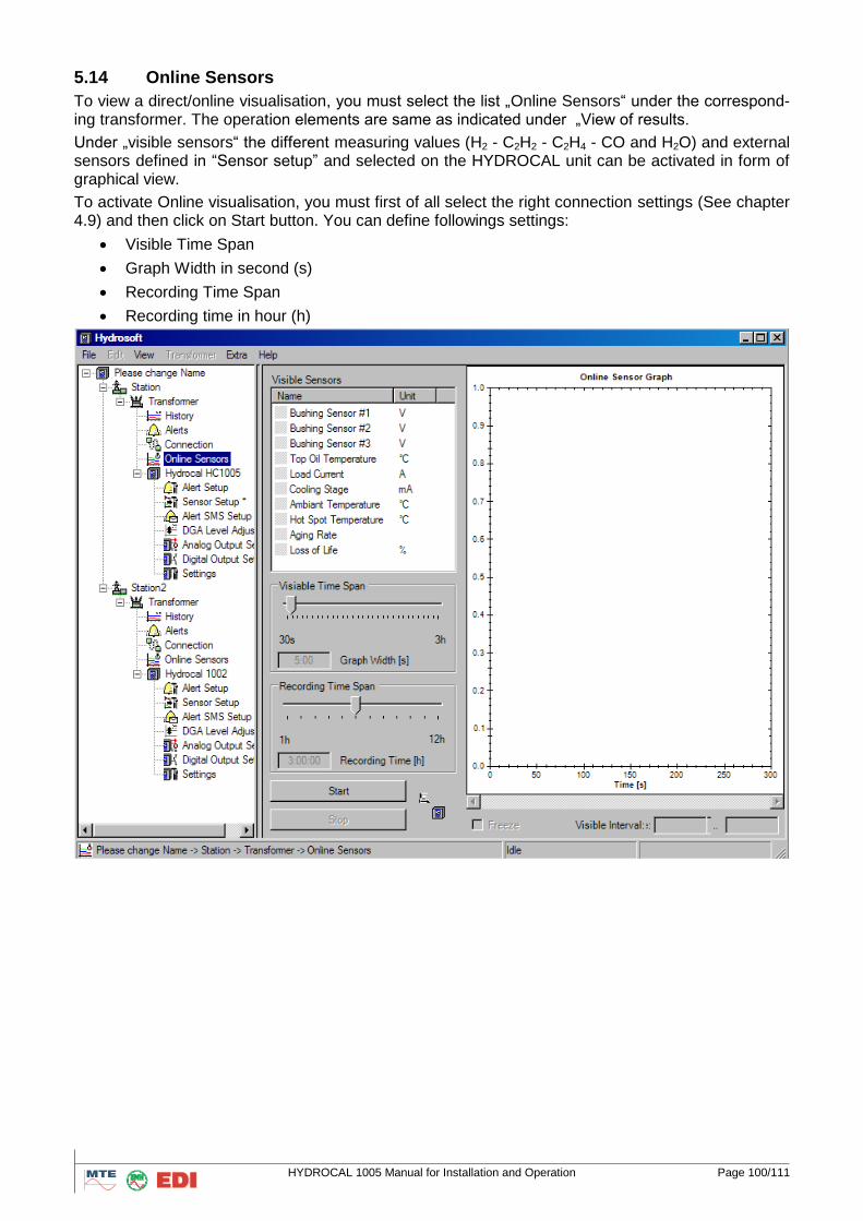
HYDROCAL 1005 Manual for Installation and Operation Page 100/111
5.14 Online Sensors
To view a direct/online visualisation, you must select the list „Online Sensors“ under the correspond-ing transformer. The operation elements are same as indicated under „View of results.
Under „visible sensors“ the different measuring values (H2 - C2H2 - C2H4 - CO and H2O) and external sensors defined in “Sensor setup” and selected on the HYDROCAL unit can be activated in form of graphical view.
To activate Online visualisation, you must first of all select the right connection settings (See chapter 4.9) and then click on Start button. You can define followings settings:
Visible Time Span
Graph Width in second (s)
Recording Time Span
Recording time in hour (h)

HYDROCAL 1005 Manual for Installation and Operation Page 101/111
6. RS 485 Wiring This chapter contains information for the wiring of the RS485 connection.
RS485
The RS485 interface is implemented as a three-wire interface. The three signal wires must be clamped onto connector #7, pin 1, pin 2 and pin 3 inside of the HYDROCAL. Care must be taken for the right polarity.
Termination, Biasing, Grounding and Protection of an RS485 Bus
Termination, biasing, grounding and protection of an RS485 Bus is a complex thing and far beyond the scope of this document. A very good source of information related to these issues can be found at www.bb-elec.com (see the section Tech Notes).
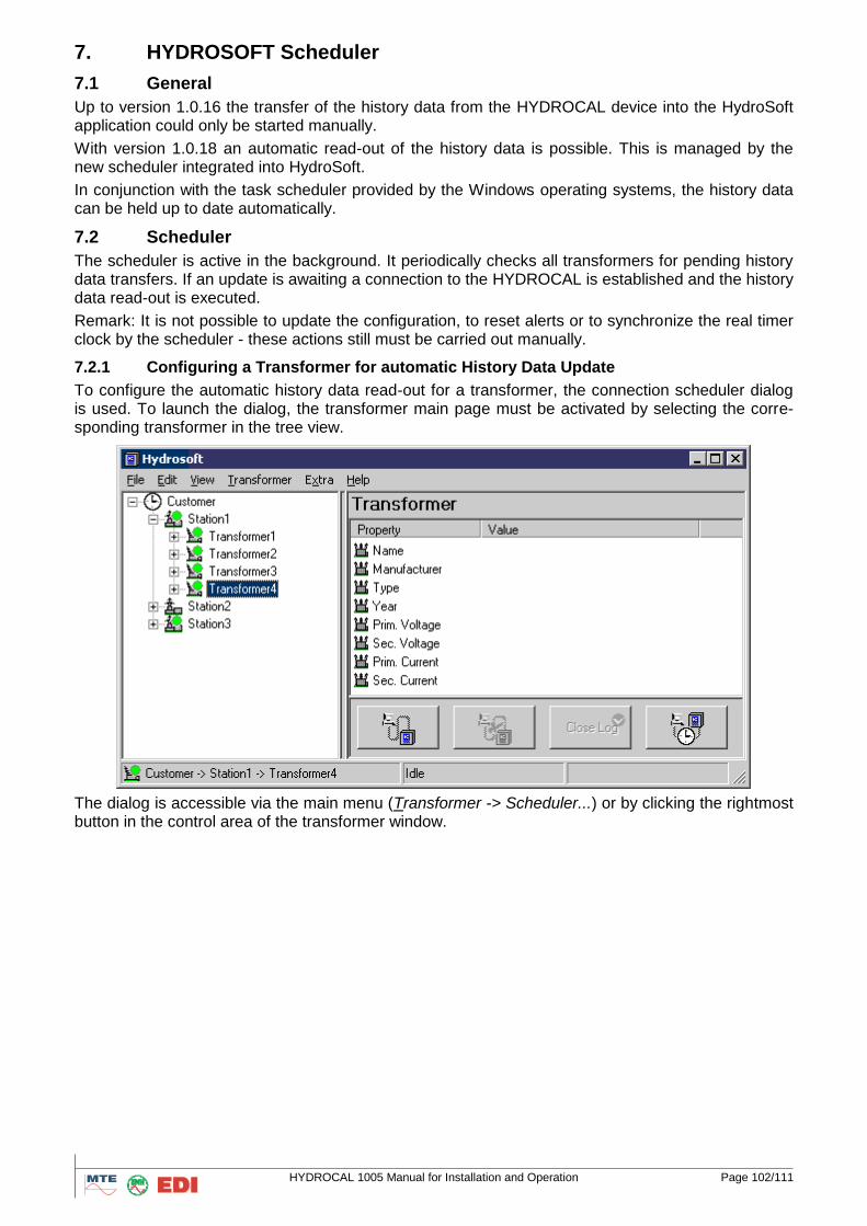
HYDROCAL 1005 Manual for Installation and Operation Page 102/111
7. HYDROSOFT Scheduler
7.1 General
Up to version 1.0.16 the transfer of the history data from the HYDROCAL device into the HydroSoft application could only be started manually.
With version 1.0.18 an automatic read-out of the history data is possible. This is managed by the new scheduler integrated into HydroSoft.
In conjunction with the task scheduler provided by the Windows operating systems, the history data can be held up to date automatically.
7.2 Scheduler
The scheduler is active in the background. It periodically checks all transformers for pending history data transfers. If an update is awaiting a connection to the HYDROCAL is established and the history data read-out is executed.
Remark: It is not possible to update the configuration, to reset alerts or to synchronize the real timer clock by the scheduler - these actions still must be carried out manually.
7.2.1 Configuring a Transformer for automatic History Data Update
To configure the automatic history data read-out for a transformer, the connection scheduler dialog is used. To launch the dialog, the transformer main page must be activated by selecting the corre-sponding transformer in the tree view.
The dialog is accessible via the main menu (Transformer -> Scheduler...) or by clicking the rightmost button in the control area of the transformer window.
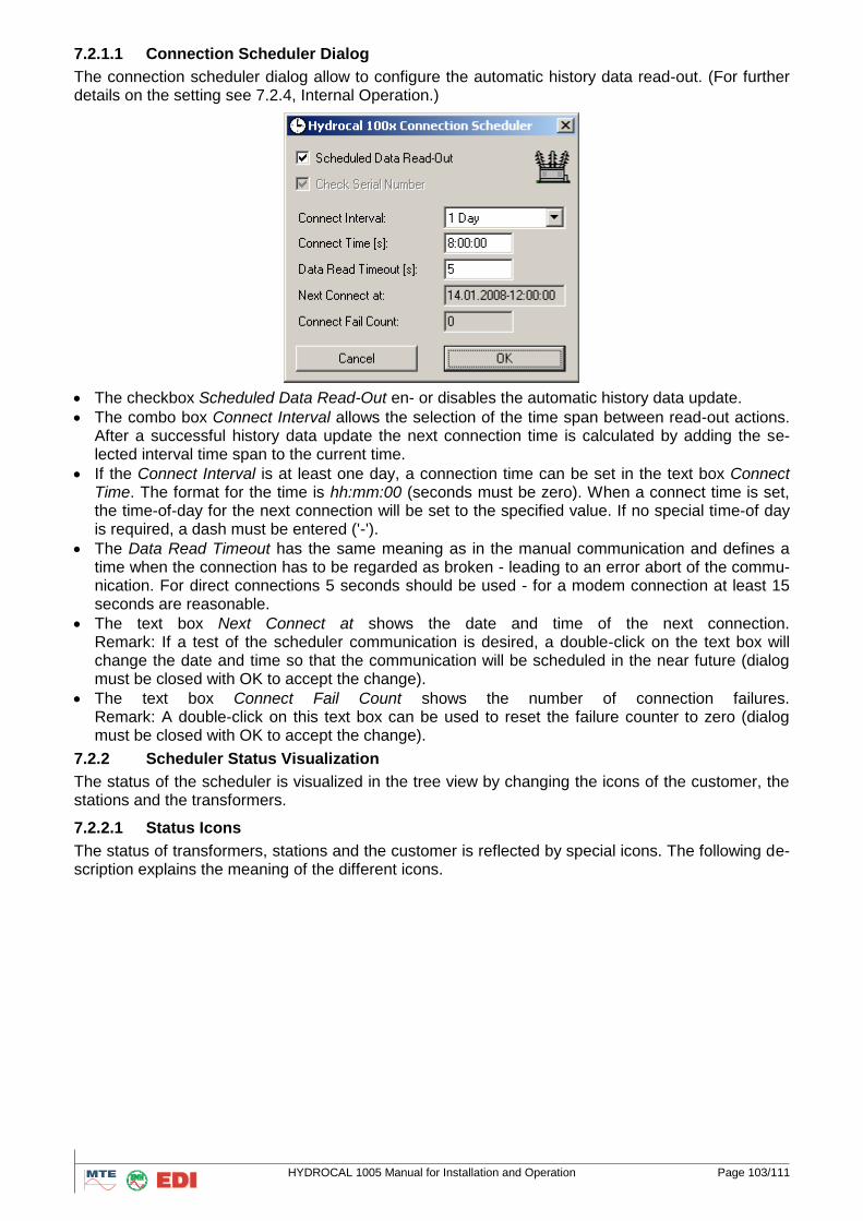
HYDROCAL 1005 Manual for Installation and Operation Page 103/111
7.2.1.1 Connection Scheduler Dialog
The connection scheduler dialog allow to configure the automatic history data read-out. (For further details on the setting see 7.2.4, Internal Operation.)
The checkbox Scheduled Data Read-Out en- or disables the automatic history data update.
The combo box Connect Interval allows the selection of the time span between read-out actions. After a successful history data update the next connection time is calculated by adding the se-lected interval time span to the current time.
If the Connect Interval is at least one day, a connection time can be set in the text box Connect Time. The format for the time is hh:mm:00 (seconds must be zero). When a connect time is set, the time-of-day for the next connection will be set to the specified value. If no special time-of day is required, a dash must be entered ('-').
The Data Read Timeout has the same meaning as in the manual communication and defines a time when the connection has to be regarded as broken - leading to an error abort of the commu-nication. For direct connections 5 seconds should be used - for a modem connection at least 15 seconds are reasonable.
The text box Next Connect at shows the date and time of the next connection. Remark: If a test of the scheduler communication is desired, a double-click on the text box will change the date and time so that the communication will be scheduled in the near future (dialog must be closed with OK to accept the change).
The text box Connect Fail Count shows the number of connection failures. Remark: A double-click on this text box can be used to reset the failure counter to zero (dialog must be closed with OK to accept the change).
7.2.2 Scheduler Status Visualization
The status of the scheduler is visualized in the tree view by changing the icons of the customer, the stations and the transformers.
7.2.2.1 Status Icons
The status of transformers, stations and the customer is reflected by special icons. The following de-scription explains the meaning of the different icons.
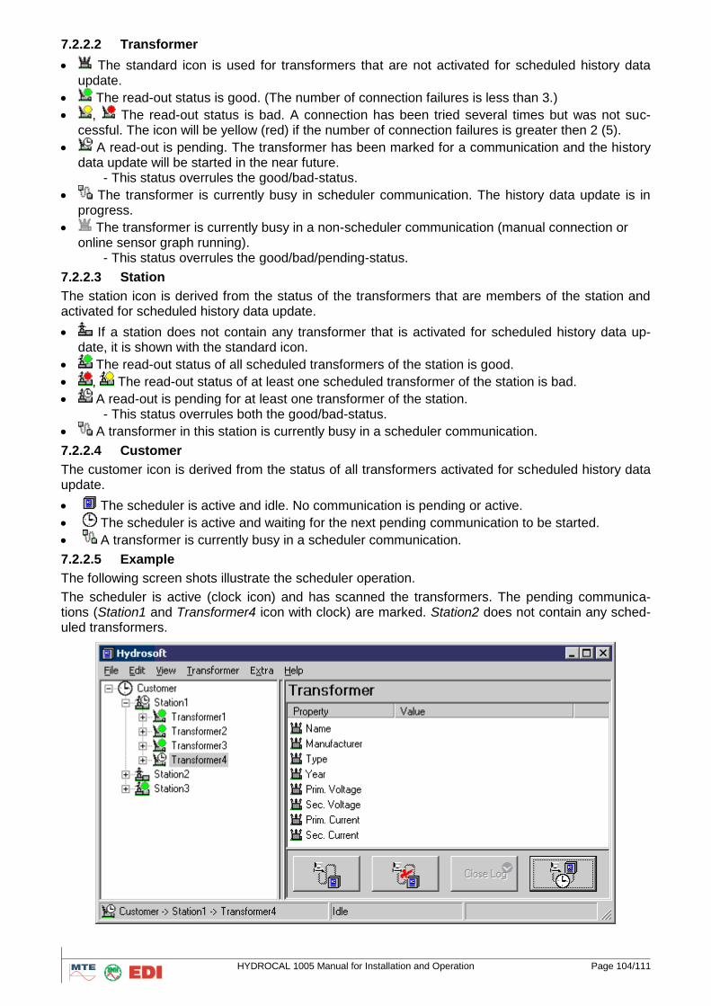
HYDROCAL 1005 Manual for Installation and Operation Page 104/111
7.2.2.2 Transformer
The standard icon is used for transformers that are not activated for scheduled history data update.
The read-out status is good. (The number of connection failures is less than 3.)
, The read-out status is bad. A connection has been tried several times but was not suc-cessful. The icon will be yellow (red) if the number of connection failures is greater then 2 (5).
A read-out is pending. The transformer has been marked for a communication and the history data update will be started in the near future.
- This status overrules the good/bad-status.
The transformer is currently busy in scheduler communication. The history data update is in progress.
The transformer is currently busy in a non-scheduler communication (manual connection or online sensor graph running).
- This status overrules the good/bad/pending-status.
7.2.2.3 Station
The station icon is derived from the status of the transformers that are members of the station and activated for scheduled history data update.
If a station does not contain any transformer that is activated for scheduled history data up-date, it is shown with the standard icon.
The read-out status of all scheduled transformers of the station is good.
, The read-out status of at least one scheduled transformer of the station is bad.
A read-out is pending for at least one transformer of the station. - This status overrules both the good/bad-status.
A transformer in this station is currently busy in a scheduler communication.
7.2.2.4 Customer
The customer icon is derived from the status of all transformers activated for scheduled history data update.
The scheduler is active and idle. No communication is pending or active.
The scheduler is active and waiting for the next pending communication to be started.
A transformer is currently busy in a scheduler communication.
7.2.2.5 Example
The following screen shots illustrate the scheduler operation.
The scheduler is active (clock icon) and has scanned the transformers. The pending communica-tions (Station1 and Transformer4 icon with clock) are marked. Station2 does not contain any sched-uled transformers.
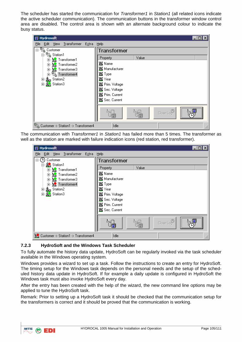
HYDROCAL 1005 Manual for Installation and Operation Page 105/111
The scheduler has started the communication for Transformer1 in Station1 (all related icons indicate the active scheduler communication). The communication buttons in the transformer window control area are disabled. The control area is shown with an alternate background colour to indicate the busy status.
The communication with Transformer1 in Station1 has failed more than 5 times. The transformer as well as the station are marked with failure indication icons (red station, red transformer).
7.2.3 HydroSoft and the Windows Task Scheduler
To fully automate the history data update, HydroSoft can be regularly invoked via the task scheduler available in the Windows operating system.
Windows provides a wizard to set up a task. Follow the instructions to create an entry for HydroSoft. The timing setup for the Windows task depends on the personal needs and the setup of the sched-uled history data update in HydroSoft. If for example a daily update is configured in HydroSoft the Windows task must also invoke HydroSoft every day.
After the entry has been created with the help of the wizard, the new command line options may be applied to tune the HydroSoft task.
Remark: Prior to setting up a HydroSoft task it should be checked that the communication setup for the transformers is correct and it should be proved that the communication is working.
HYDROCAL 1005 Manual for Installation and Operation Page 106/111
7.2.3.1 Command Line Options for Windows Task Scheduler
HydroSoft comes with two new command line options for use in conjunction with the scheduled his-tory data update.
Example:
<path>\Hydrosoft -IdleClose 0:15:00 -Minimized
7.2.3.2 IdleClose
The IdleClose command line option can be given to let the application terminate after all history data updates have be carried out. Following the command line option, a time span argument must be supplied, that defines the idle close time. The syntax for the close time is [hh:[mm:]]ss.
When the HydroSoft scheduler scans the transformers for pending history data updates, it deter-mines the shortest time span, when the next communication has to be started. If this time span is greater than the idle close time, the application exits. When a daily update is configured a reason-able default for the idle close time is 15 minutes. This would allow for repeated communication tries (in case of failure), but exit, when the communication fails too often.
7.2.3.3 Minimized
The Minimized command line option can be given to let the application start minimized.
Remark: This option will also suppress the warning message, if the HydroSoft data directory is in use by a manually started HydroSoft application. A Windows task scheduler started instance of Hydro-Soft can immediately exit, if a manually started HydroSoft application is already running.
7.2.4 Internal Operation
This is a more detailed description of the internal operation of the scheduler (the terms in italics are related to the data configured in the connection scheduler dialog).
The scheduler runs as a separate thread in the background of HydroSoft. Approximately every 15 seconds all transformers are checked if scheduled data read-out is active. Once a transformer is ac-tive, a further check is made, whether the current time is greater than the next connect at time. This way a list of pending connections is generated.
If the list of pending connections is non empty, it is processed step by step, i.e. the list is traversed and all pending connection requests are executed before a new list is build.
For each transformer a try to update the data is done. On success the connect fail count is set to zero and the next connect at time is updated (current time plus connect interval - optionally aligned to the connect time).
In case of an error the connect fail count is incremented and the next connect at time is set based on the current connect fail count. If the count is less than 3, a connection retry with 5 minutes delay is set, for a count less than 5 the retry is scheduled in 10 minutes. If the count exceeds 5, the next retry is scheduled to the current time plus the connect interval (- optionally aligned to the connect time, i.e. the same time as if the connection had succeeded).
When the scheduler detects, that a time span of 3 times the connect interval has expired since the last start of the application, the connect fail count is reset to 4. This will lead to a double communica-tion try for a transformer with a bad status when the application has not been used for a longer time period.
Because of the internal operation the following notes apply:
Changes applied through the connection scheduler dialog take some time until they are reflected in the tree view.
Even if the read-out status of a transformer is bad, there will always be a try to update the data with the configured connect interval.
A manual update of the history data does not update the next connect at time of the scheduler. Even if an update occurs immediately before the next connect at time, the scheduled data read-out will still be executed.
A log file 'Scheduler.log' is created in the root if the HydroSoft data directory. If a problem arises with the scheduler a look into this file may help finding the cause. The log file entries are always written in English.

HYDROCAL 1005 Manual for Installation and Operation Page 107/111
7.2.5 Data Directory Lock
HydroSoft now protects the data directory by a lock. Once an instance of HydroSoft is working on a data directory no second instance of HydroSoft can operate on the same data.
This locking is introduced to keep data integrity in case a user is running HydroSoft and a back-ground instance of HydroSoft (started via the Windows task scheduler) also tries to work on the data.
HydroSoft will exit with a return code of 2 if the data directory is locked.
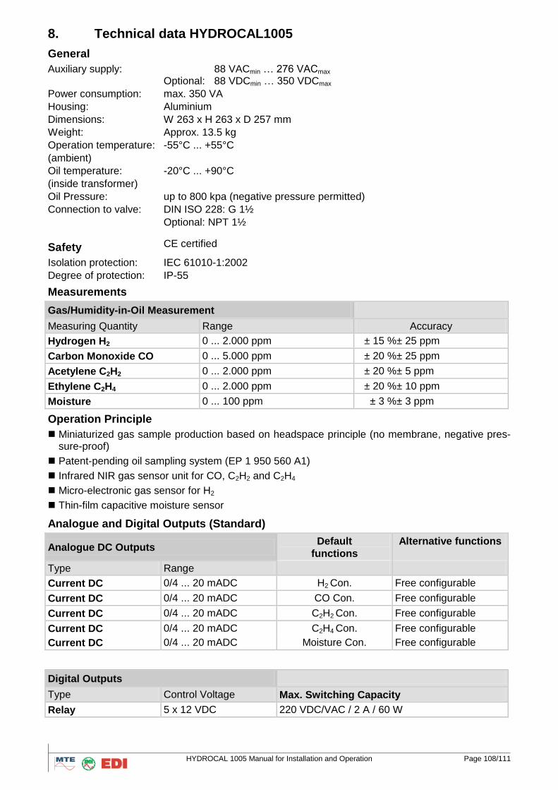
HYDROCAL 1005 Manual for Installation and Operation Page 108/111
8. Technical data HYDROCAL1005
General
Auxiliary supply: 88 VACmin … 276 VACmax Optional: 88 VDCmin … 350 VDCmax
Power consumption: max. 350 VA
Housing: Aluminium
Dimensions: W 263 x H 263 x D 257 mm
Weight: Approx. 13.5 kg
Operation temperature:
(ambient)
-55°C ... +55°C
Oil temperature:
(inside transformer)
-20°C ... +90°C
Oil Pressure: up to 800 kpa (negative pressure permitted)
Connection to valve: DIN ISO 228: G 1½
Optional: NPT 1½
Safety CE certified
Isolation protection: IEC 61010-1:2002
Degree of protection: IP-55
Measurements
Gas/Humidity-in-Oil Measurement
Measuring Quantity Range Accuracy
Hydrogen H2 0 ... 2.000 ppm ± 15 %± 25 ppm
Carbon Monoxide CO 0 ... 5.000 ppm ± 20 %± 25 ppm
Acetylene C2H2 0 ... 2.000 ppm ± 20 %± 5 ppm
Ethylene C2H4 0 ... 2.000 ppm ± 20 %± 10 ppm
Moisture 0 ... 100 ppm ± 3 %± 3 ppm
Operation Principle
Miniaturized gas sample production based on headspace principle (no membrane, negative pres-sure-proof)
Patent-pending oil sampling system (EP 1 950 560 A1)
Infrared NIR gas sensor unit for CO, C2H2 and C2H4
Micro-electronic gas sensor for H2
Thin-film capacitive moisture sensor
Analogue and Digital Outputs (Standard)
Analogue DC Outputs Default
functions
Alternative functions
Type Range
Current DC 0/4 ... 20 mADC H2 Con. Free configurable
Current DC 0/4 ... 20 mADC CO Con. Free configurable
Current DC 0/4 ... 20 mADC C2H2 Con. Free configurable
Current DC 0/4 ... 20 mADC C2H4 Con. Free configurable
Current DC 0/4 ... 20 mADC Moisture Con. Free configurable
Digital Outputs
Type Control Voltage Max. Switching Capacity
Relay 5 x 12 VDC 220 VDC/VAC / 2 A / 60 W
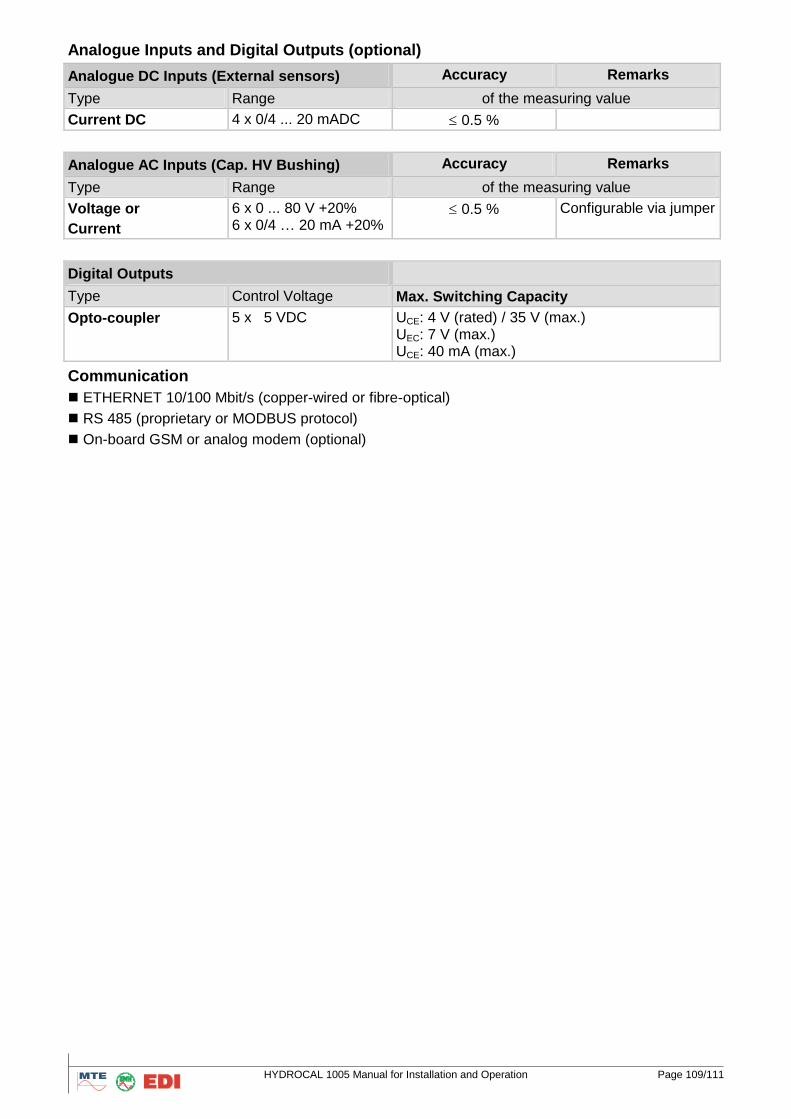
HYDROCAL 1005 Manual for Installation and Operation Page 109/111
Analogue Inputs and Digital Outputs (optional)
Analogue DC Inputs (External sensors) Accuracy Remarks
Type Range of the measuring value
Current DC 4 x 0/4 ... 20 mADC 0.5 %
Analogue AC Inputs (Cap. HV Bushing) Accuracy Remarks
Type Range of the measuring value
Voltage or
Current
6 x 0 ... 80 V +20% 6 x 0/4 … 20 mA +20%
0.5 % Configurable via jumper
Digital Outputs
Type Control Voltage Max. Switching Capacity
Opto-coupler 5 x 5 VDC UCE: 4 V (rated) / 35 V (max.) UEC: 7 V (max.) UCE: 40 mA (max.)
Communication
ETHERNET 10/100 Mbit/s (copper-wired or fibre-optical)
RS 485 (proprietary or MODBUS protocol)
On-board GSM or analog modem (optional)
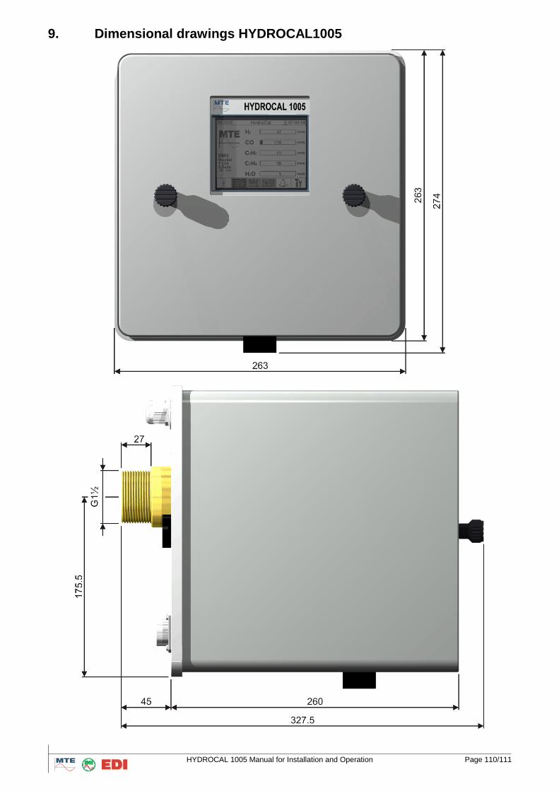
HYDROCAL 1005 Manual for Installation and Operation Page 110/111
9. Dimensional drawings HYDROCAL1005
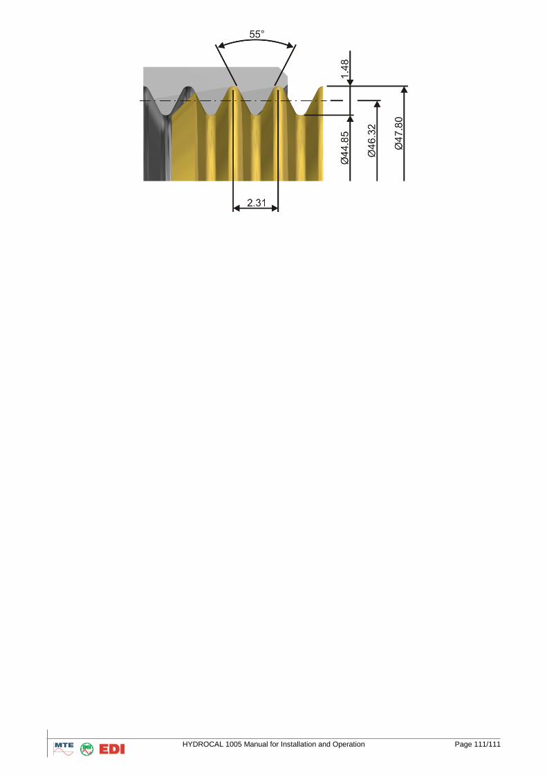
HYDROCAL 1005 Manual for Installation and Operation Page 111/111