Embed Size (px)
Citation preview

Hydraulics Product Catalog
With Preferred & Spotlight Delivery
Programs Section

1
Electric Drivesand Controls Hydraulics
Linear Motion andAssembly Technologies Pneumatics Service
The Drive & Control Company
For a complete copy of the
data sheets in this catalog,
visit our website at:
www.boschrexroth-us.com
u Products and Solutions
u Industrial Hy drau lics
u Products and Catalogs
u Preferred Product
Catalog
1
– External gear pump – F, N & G ......................................... 2
– External gear motors – F & N ............................................ 8
– Internal gear pump, fi xed displacement
• PGF ....................................................................................11
• PGH ...................................................................................14
– Fixed displacement vane pump – PVV..........................17
– Variable displacement vane pumps – PSV ..................19
– Radial piston pump – R4 .................................................21
– Radial piston pump – R4 mini .........................................23
– Variable vane pumps – VPV ............................................25
– Radial piston motor, low speed, high torque
• MCR 03 ............................................................................28
• MCR 05 ............................................................................33
• MCR 10 ............................................................................37
• MCR 15 ............................................................................41
• MCR 20 ............................................................................44
– Fixed displacement motor, open and closed –
AA2FM (A2FM) ..................................................................47
– Fixed displacement motor, open and closed –
A10FM, standard version; A10FE, plug-in version .....52
– Fixed displacement pump, open –
AA2FO (A2FO) ..................................................................56
– Variable displacement motor, open and closed –
AA6VM (A6VM) ..................................................................60
– Dual displacement motor, open and closed –
A10VM; A10VE, plug-in version .....................................64
– Variable displacement pump, closed – AA4VG .........68
Section 1
Pumps and Motors
– Variable displacement pump, open – A4VSO ............73
– Axial piston variable pump for HFC fl uids
(water-glycol) – AA4VSO ................................................78
– Variable displacement pump, closed – A4VSG .........82
– Axial piston-compact unit – AA4CSG (A4CSG) .......87
– Variable displacement pump, open – AA11VO ..........91
– Variable displacement pump, open – A10V(S)O .......95
– Variable displacement pump, open – A10VO ............99
– Variable displacement pump, open –
AA10VSO (A10VSO: sizes 10 & 18) ........................103
– Variable displacement pump, open – A10VSO .......107
– Variable displacement pump, open – A10VNO ......111
– Variable displacement pump, closed –
AA10VG ............................................................................114
– Closed loop pressure and fl ow control system –
SYDFE1 ............................................................................118
– Pressure and fl ow closed loop – SYDFEE ...............121
– Pressure-fl ow closed loop control – SYHDFEE ......124

Pumps and Motors 2 Section 1
Electric Drivesand Controls Hydraulics
Linear Motion andAssembly Technologies Pneumatics Service
See Section 16 for applicable
Preferred/Spotlight part numbers
and unit price.
Series N Series F
Extracted from RA 10 097/02.06Page 1 of 6
Issue: 06.06
External gear pumps
Series F, N, & G
Fixed displacement pumps
Sizes 4.1...63.0 cm3 (0.26...3.84 in3)
– Displacements of 4cc to 63cc
– Plain bearings for heavy duty applications
– Drive shafts SAE or ISO
– Multiple Pump Assemblies
– Port connections: fl ange or threaded
– Optimized pressure pulsation, which reduces noise levels and
vibration excitation in the system
– Consistent high quality
– Considerably longer life due to reinforced shaft and housingSeries G
Pumps and Motors 3 Section 1
Electric Drivesand Controls Hydraulics
Linear Motion andAssembly Technologies Pneumatics Service
See Section 16 for applicable
Preferred/Spotlight part numbers
and unit price.
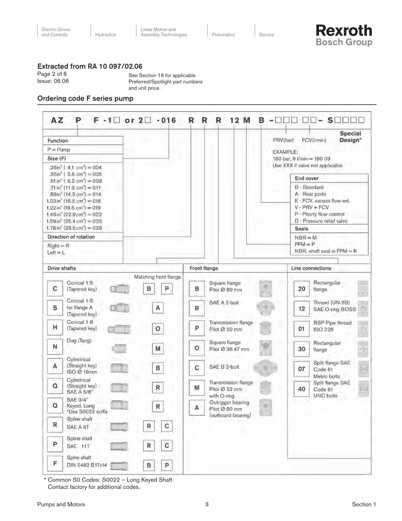
Ordering code F series pump
* Common S0 Codes: S0022 – Long Keyed Shaft
Contact factory for additional codes.
Extracted from RA 10 097/02.06Page 2 of 6
Issue: 06.06

Pumps and Motors 4 Section 1
Electric Drivesand Controls Hydraulics
Linear Motion andAssembly Technologies Pneumatics Service
See Section 16 for applicable
Preferred/Spotlight part numbers
and unit price.
Ordering code N series pump
* Common S0 Codes: S0075 – Tapered Shaft
Contact factory for additional codes.
Extracted from RA 10 097/02.06Page 3 of 6
Issue: 06.06

Pumps and Motors 5 Section 1
Electric Drivesand Controls Hydraulics
Linear Motion andAssembly Technologies Pneumatics Service
See Section 16 for applicable
Preferred/Spotlight part numbers
and unit price.
Ordering code G series pump
Note: Consult factory for availability
Extracted from RA 10 097/02.06Page 4 of 6
Issue: 06.06

Pumps and Motors 6 Section 1
Electric Drivesand Controls Hydraulics
Linear Motion andAssembly Technologies Pneumatics Service
See Section 16 for applicable
Preferred/Spotlight part numbers
and unit price.
Ordering code for multiple pumps
* Contact factory for availability of units with no ordering number listed.
** Refer to page 18 for SAE O-Ring Boss specifications and dimensions.
Extracted from RA 10 097/02.06Page 5 of 6
Issue: 06.06
Pumps and Motors 7 Section 1
Electric Drivesand Controls Hydraulics
Linear Motion andAssembly Technologies Pneumatics Service
See Section 16 for applicable
Preferred/Spotlight part numbers
and unit price.
Extracted from RA 10 097/02.06Page 6 of 6
Issue: 06.06
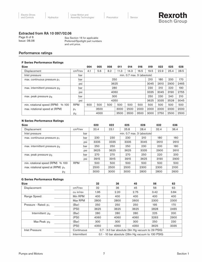
Performance ratings
F Series Performance RatingsS 820520220910610410110800500400ezi
mctnemecalpsiD 3/rev 4.1 5.6 8.2 11.3 14.3 16.5 19.5 22.9 25.4 28.5
)etulosba(3.xam7.0.nimraberusserptelnI
max. continuous pressure p1 071002081012052rab
56420092016254035263isp
max. intermittent pressure p2 091022012032082rab
55720913540353330604isp
max. peak pressure p3 012042032052003rab
54038253533352630534isp
min. rotational speed (RPM) % 100 RPM 600 500 500 500 500 500 500 500 500 500
max. rotational speed at (RPM) p10 3500 3000 2500 2000 2000 2000 2000 2000
max. Drehzahl bei p20 4000 3500 3500 3500 3000 2750 2500 2500
N Series Performance Ratings630230820520220020eziS
mctnemecalpsiD 3/rev 20.4 23.1 25.8 28.4 32.4 36.4
Inlet pressure bar min. 0.7 max. 3 (absolute)
max. continuous pressure p1 bar 230 230 230 210 180 160
psi 3335 3335 3335 3045 2610 2610
max. intermittent pressure p2 bar 250 250 250 230 200 180
psi 3625 3625 3625 3335 2900 2610
max. peak pressure p3 bar 270 270 270 250 220 200
psi 3915 3915 3915 3625 3190 2900
min. rotational speed (RPM) % 100 RPM 500 500 500 500 500 500
max. rotational speed at (RPM) p1 0 2500 2500 2500 2300 2300 2100
max. Drehzahl bei p2 0 3000 3000 3000 2800 2800 2600
G Series Performance Ratings3665546323eziS
mc:tnemecalpsiD 3/rev 32 36 45 56 63
cu in/rev 1.95 2.20 2.75 3.42 3.84
Range Speed: Min RPM 400 400 400 400 400
Max RPM 2800 2800 2600 2300 2300
Pressure - Rated: p1 (Bar) 250 250 250 195 170
(PSI) 3625 3625 3625 2828 2465
Intermittent: p2 (Bar) 280 280 280 225 200
(PSI) 4060 4060 4060 3263 2900
Max Peak: p3 (Bar) 300 300 300 250 230
(PSI) 4350 4350 4350 3625 3335
GISP92otmuucavgHni9(etulosbarab0.3-7.0suounitnoC:erusserPtelnI
Intermittent 0.1 - 10 bar absolute (26in Hg vacuum to 130 PSIG

Pumps and Motors 8 Section 1
Electric Drivesand Controls Hydraulics
Linear Motion andAssembly Technologies Pneumatics Service
See Section 16 for applicable
Preferred/Spotlight part numbers
and unit price.
Extracted from RA 14 025/08.06Page 1 of 3
Issue: 06.06
External gear motors
Series F & N
Fixed displacement motors
Sizes 8.2...36.4 cm3 (0.51...2.28 in3)
– Plain bearings for heavy duty applications
– Drive shafts SAE or ISO
– Port connections: fl ange or threaded
– Consistent high quality
– Considerably longer life due to reinforced shaft and housing
Ratings and specifi cations

Pumps and Motors 9 Section 1
Electric Drivesand Controls Hydraulics
Linear Motion andAssembly Technologies Pneumatics Service
See Section 16 for applicable
Preferred/Spotlight part numbers
and unit price.
* Common S0 Codes: S0018 = Cross check valve in rear cover (internal case drain), S0022 = Long keyed shaft,
S0030 = S0018 + S0022, S0028 = Pressure relief valve and anti-cavitation valve.
Ordering code F series motor
Extracted from RA 14 025/08.06Page 2 of 3
Issue: 06.06
Pumps and Motors 10 Section 1
Electric Drivesand Controls Hydraulics
Linear Motion andAssembly Technologies Pneumatics Service
See Section 16 for applicable
Preferred/Spotlight part numbers
and unit price.
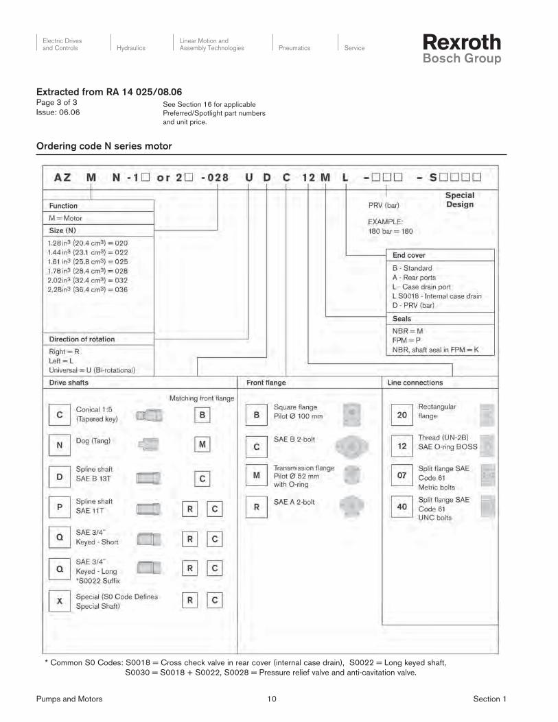
Ordering code N series motor
* Common S0 Codes: S0018 = Cross check valve in rear cover (internal case drain), S0022 = Long keyed shaft,
S0030 = S0018 + S0022, S0028 = Pressure relief valve and anti-cavitation valve.
Extracted from RA 14 025/08.06Page 3 of 3
Issue: 06.06

Pumps and Motors 11 Section 1
Electric Drivesand Controls Hydraulics
Linear Motion andAssembly Technologies Pneumatics Service
See Section 16 for applicable
Preferred/Spotlight part numbers
and unit price.
Extracted from RE 10213/04.05Page 1 of 3
Issue: 06.06
Internal gear pump, fi xed displacement
Model PGF
Frame sizes 1, 2 and 3
Component series: 2X (FS1 and 2)
3X (FS3)
Max. operating pressure up to 250 bar (3626 PSI)
Max. displacement 1.7 to 40 cm3 (0.10 to 2.44 in3)
– Fixed displacement
– Low operating noise
– Low fl ow pulsation
– High effi ciency even at low viscosity due to sealing
gap compensation
– Long service life due to plain bearings and sealing
gap compensation
– Suitable for a wide viscosity and speed range
– Excellent suction characteristics
– All frame sizes can be combined with each other
– Can be combined with PGH internal gear pumps,
PV7 vane pumps and axial piston pumps
– Valve technology can be integrated in the cover plate on inquiry
Model PGF1... for direct mounting
Model PGF3... for direct mounting
Pumps and Motors 12 Section 1
Electric Drivesand Controls Hydraulics
Linear Motion andAssembly Technologies Pneumatics Service
See Section 16 for applicable
Preferred/Spotlight part numbers
and unit price.
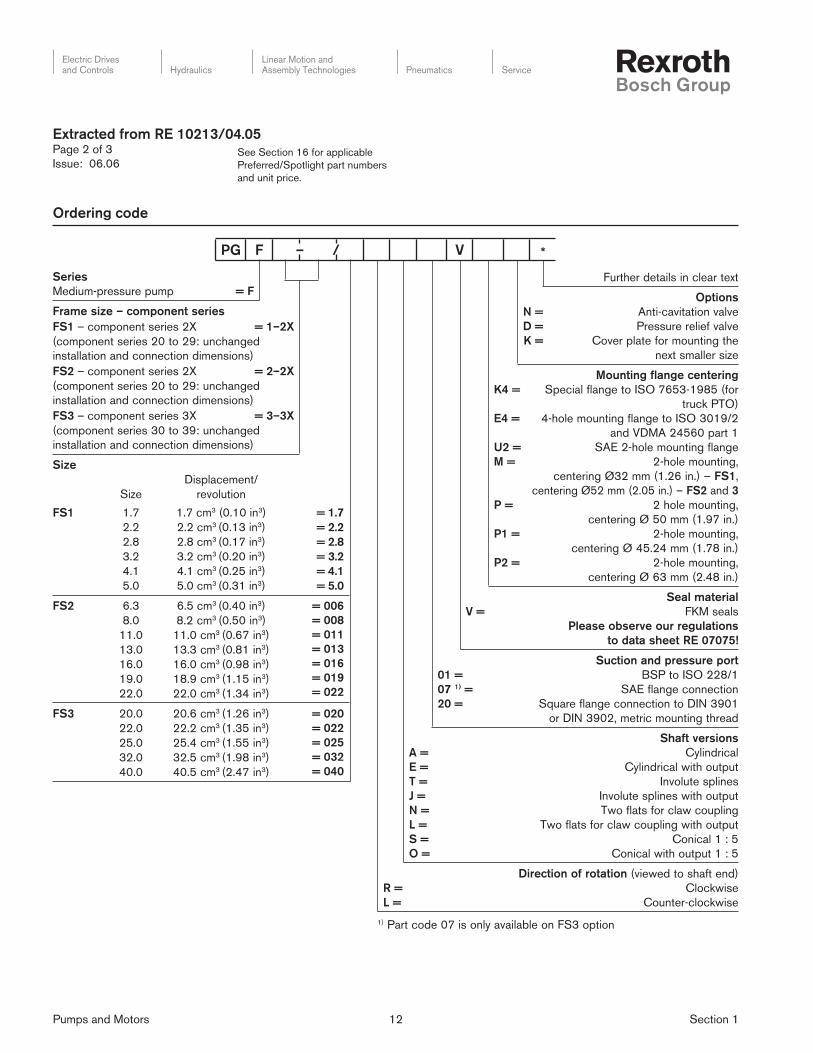
Ordering code
Extracted from RE 10213/04.05Page 2 of 3
Issue: 06.06
Series
Medium-pressure pump = F
Frame size – component series
FS1 – component series 2X = 1–2X
(component series 20 to 29: unchanged
installation and connection dimensions)
FS2 – component series 2X = 2–2X
(component series 20 to 29: unchanged
installation and connection dimensions)
FS3 – component series 3X = 3–3X
(component series 30 to 39: unchanged
installation and connection dimensions)
Size
Size
Displacement/
revolution
FS1 1.7
2.2
2.8
3.2
4.1
5.0
1.7 cm3 (0.10 in3)
2.2 cm3 (0.13 in3)
2.8 cm3 (0.17 in3)
3.2 cm3 (0.20 in3)
4.1 cm3 (0.25 in3)
5.0 cm3 (0.31 in3)
= 1.7
= 2.2
= 2.8
= 3.2
= 4.1
= 5.0
FS2 6.3
8.0
11.0
13.0
16.0
19.0
22.0
6.5 cm3 (0.40 in3)
8.2 cm3 (0.50 in3)
11.0 cm3 (0.67 in3)
13.3 cm3 (0.81 in3)
16.0 cm3 (0.98 in3)
18.9 cm3 (1.15 in3)
22.0 cm3 (1.34 in3)
= 006
= 008
= 011
= 013
= 016
= 019
= 022
FS3 20.0
22.0
25.0
32.0
40.0
20.6 cm3 (1.26 in3)
22.2 cm3 (1.35 in3)
25.4 cm3 (1.55 in3)
32.5 cm3 (1.98 in3)
40.5 cm3 (2.47 in3)
= 020
= 022
= 025
= 032
= 040
Further details in clear text
N =
D =
K =
Options
Anti-cavitation valve
Pressure relief valve
Cover plate for mounting the
next smaller size
K4 =
E4 =
U2 =
M =
P =
P1 =
P2 =
Mounting flange centering
Special flange to ISO 7653-1985 (for
truck PTO)
4-hole mounting flange to ISO 3019/2
and VDMA 24560 part 1
SAE 2-hole mounting flange
2-hole mounting,
centering Ø32 mm (1.26 in.) – FS1,
centering Ø52 mm (2.05 in.) – FS2 and 3
2 hole mounting,
centering Ø 50 mm (1.97 in.)
2-hole mounting,
centering Ø 45.24 mm (1.78 in.)
2-hole mounting,
centering Ø 63 mm (2.48 in.)
V =
Seal material
FKM seals
Please observe our regulations
to data sheet RE 07075!
01 =
07 1) =
20 =
Suction and pressure port
BSP to ISO 228/1
SAE flange connection
Square flange connection to DIN 3901
or DIN 3902, metric mounting thread
A =
E =
T =
J =
N =
L =
S =
O =
Shaft versions
Cylindrical
Cylindrical with output
Involute splines
Involute splines with output
Two flats for claw coupling
Two flats for claw coupling with output
Conical 1 : 5
Conical with output 1 : 5
R =
L =
Direction of rotation (viewed to shaft end)
Clockwise
Counter-clockwise
1) Part code 07 is only available on FS3 option
PG F – / V *

Pumps and Motors 13 Section 1
Electric Drivesand Controls Hydraulics
Linear Motion andAssembly Technologies Pneumatics Service
See Section 16 for applicable
Preferred/Spotlight part numbers
and unit price.
Technical data
Extracted from RE 10213/04.05Page 3 of 3
Issue: 06.06
Frame Size 1
Nominal Displacement cc/rev. 1.7 2.2 2.8 3.2 4.1 5.0
Actual Displacement in3/rev. 0.10 0.13 0.17 0.20 0.25 0.31
Max. Outlet Pressure psig 2610 3045 2610
Inlet Pressure Range psia 11.8 to 29.0
Viscosity SUS 55 to 1450
Bulk Fluid Temperature °F –4 to +212
Minimum Speed rpm 600
Maximum Speed rpm 4500 3600 4000 3600
Rotation RH or LH possible (not capable of bi-directional rotation)
Frame Size 2
Nominal Displacement cc/rev. 6.3 8 11 13 16 19 22
Actual Displacement in3/rev. 0.40 0.50 0.67 0.81 0.98 1.15 1.34
Max. Outlet Pressure psig 3045 2610
Inlet Pressure Range psia 8.9 to 29.0
Viscosity SUS 55 to 1450
Bulk Fluid Temperature °F –4 to +212
Minimum Speed rpm 600
Maximum Speed rpm 3600 3000
Rotation RH or LH possible (not capable of bi-directional rotation)
Frame Size 3
Nominal Displacement cc/rev. 20 22 25 32 40
Actual Displacement in3/rev. 1.26 1.35 1.55 1.98 2.47
Max. Outlet Pressure psig 3045 2610
Inlet Pressure Range psia 8.9 to 29.0
Viscosity SUS 55 to 1450
Bulk Fluid Temperature °F –4 to +212
Minimum Speed rpm 500
Maximum Speed rpm 3600 3400 3200 3000 2500
Rotation RH or LH possible (not capable of bi-directional rotation)

Pumps and Motors 14 Section 1
Electric Drivesand Controls Hydraulics
Linear Motion andAssembly Technologies Pneumatics Service
See Section 16 for applicable
Preferred/Spotlight part numbers
and unit price.
Extracted from RE 10223/03.05Page 1 of 3
Issue: 06.06
Internal gear pump, fi xed displacement
Model PGH
Frame sizes 2, 3, 4 and 5
Component series: 2X
Max. operating pressure up to 350 bar (5076 PSI)
Max. displacement 250 cm3 (15.26 in3)
– Fixed displacement
– Low operating noise
– Low fl ow pulsation
– High effi ciency even at low speed and viscosity due to sealing
gap compensation
– Suitable for wide viscosity and speed ranges
– All frame sizes and nominal sizes can freely combined with
each other
– Can be combined with PGF internal gear pumps, vane pumps
and axial piston pumps
– Suitable for operation with HFC fl uids
(seal version “W“)
Model PGH... with SAE 2-hole mounting fl ange
Double pump model PGH4 + PGH3

Pumps and Motors 15 Section 1
Electric Drivesand Controls Hydraulics
Linear Motion andAssembly Technologies Pneumatics Service
See Section 16 for applicable
Preferred/Spotlight part numbers
and unit price.
Series
High pressure pump
= H
Frame size
FS2
FS3
FS4
FS5
= 2
= 3
= 4
= 5
Component series:
Component series 20 to 29
= 2X
(20 to 29: unchanged installation and
connection dimensions)
Size
Size
Displacement/
revolution
FS2 5.0
6.3
8.0
5.2 cm3 (0.32 in3)
6.5 cm3 (0.40 in3)
8.2 cm3 (0.50 in3)
= 005
= 006
= 008
FS3 11
13
16
11.0 cm3 (0.67 in3)
13.3 cm3 (0.81 in3)
16.0 cm3 (0.98 in3)
= 011
= 013
= 016
FS4 20
25
32
40
50
63
80
100
20.1 cm3 (1.23 in3)
25.3 cm3 (1.54 in3)
32.7 cm3 (2.00 in3)
40.1 cm3 (2.45 in3)
50.7 cm3 (3.09 in3)
65.5 cm3 (4.00 in3)
80.3 cm3 (4.90 in3)
101.4 cm3 (6.19 in3)
= 020
= 025
= 032
= 040
= 050
= 063
= 080
= 100
FS5 63
80
100
125
160
200
250
64.7 cm3 (3.95 in3)
81.4 cm3 (4.97 in3)
100.2 cm3 (6.11 in3)
125.3 cm3 (7.65 in3)
162.8 cm3 (9.93 in3)
200.4 cm3 (12.23 in3)
250.5 cm3 (15.29 in3)
= 063
= 080
= 100
= 125
= 160
= 200
= 250
Ordering code
Extracted from RE 10223/03.05Page 2 of 3
Issue: 06.06
PG H – 2X / *
Further details in clear text
U2 =
E4 = 1)
Mounting flange
SAE 2-hole mounting flange
ISO 4-hole mounting flange to
ISO 3019/2 and
VDMA 24560 part 1
V =
W = 2)
Seal material
FKM seals
Shaft seal ring made of NBR
(other seals made of FKM)
07 =
11 =
Suction and pressure port to SAE 3)
Pressure port for standard pressure series
Pressure port for high pressure series
E =
R =
Shaft version
Cylindrical
SAE involute splined shaft
R =
L =
Direction of rotation (viewed to shaft end)
Clockwise
Counter-clockwise
1) Only in conjunction with cylindrical shaft (to VDMA),
frame sizes 4 and 5 only, clockwise rotation only2) FS4 and FS5 only for operation with HFC fl uid 3) A type of connection 07 or 11 is determined for each size:
07: PGH2-2X/005/006/008…
PGH3-2X/011/013/016…
PGH4-2X/063/080/100…
PGH5-2X/160/200/250…
11: PGH4-2X/020/025/032/040/050…
PGH5-2X/063/080/100/125…
The suction ports are standard pressure series ports
(for the dimensions, see page 17).
Pumps and Motors 16 Section 1
Electric Drivesand Controls Hydraulics
Linear Motion andAssembly Technologies Pneumatics Service
See Section 16 for applicable
Preferred/Spotlight part numbers
and unit price.
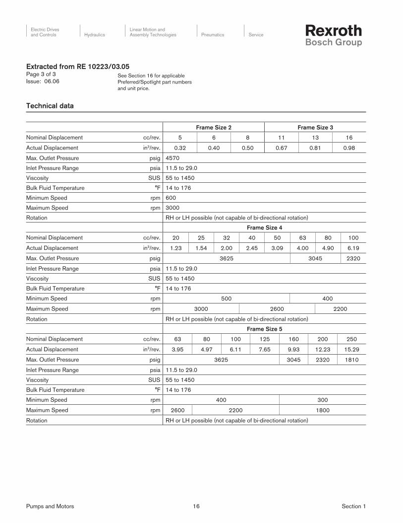
Technical data
Extracted from RE 10223/03.05Page 3 of 3
Issue: 06.06
Frame Size 2 Frame Size 3
Nominal Displacement cc/rev. 5 6 8 11 13 16
Actual Displacement in3/rev. 0.32 0.40 0.50 0.67 0.81 0.98
Max. Outlet Pressure psig 4570
Inlet Pressure Range psia 11.5 to 29.0
Viscosity SUS 55 to 1450
Bulk Fluid Temperature °F 14 to 176
Minimum Speed rpm 600
Maximum Speed rpm 3000
Rotation RH or LH possible (not capable of bi-directional rotation)
Frame Size 4
Nominal Displacement cc/rev. 20 25 32 40 50 63 80 100
Actual Displacement in3/rev. 1.23 1.54 2.00 2.45 3.09 4.00 4.90 6.19
Max. Outlet Pressure psig 3625 3045 2320
Inlet Pressure Range psia 11.5 to 29.0
Viscosity SUS 55 to 1450
Bulk Fluid Temperature °F 14 to 176
Minimum Speed rpm 500 400
Maximum Speed rpm 3000 2600 2200
Rotation RH or LH possible (not capable of bi-directional rotation)
Frame Size 5
Nominal Displacement cc/rev. 63 80 100 125 160 200 250
Actual Displacement in3/rev. 3.95 4.97 6.11 7.65 9.93 12.23 15.29
Max. Outlet Pressure psig 3625 3045 2320 1810
Inlet Pressure Range psia 11.5 to 29.0
Viscosity SUS 55 to 1450
Bulk Fluid Temperature °F 14 to 176
Minimum Speed rpm 400 300
Maximum Speed rpm 2600 2200 1800
Rotation RH or LH possible (not capable of bi-directional rotation)

Pumps and Motors 17 Section 1
Electric Drivesand Controls Hydraulics
Linear Motion andAssembly Technologies Pneumatics Service
See Section 16 for applicable
Preferred/Spotlight part numbers
and unit price.
Single pump model PVV2-1X/...A15D..
Double pump model PVV21-1X/...A15DD..
Extracted from RE 10335/11.02Page 1 of 2
Issue: 01.01
Fixed displacement vane pump
Model PVV
Series 1X
Max. pressure up to 210 bar (3050 PSI)
Max. displacement 18–193 cm3 (1.09–11.78 in3)
– 4 frame sizes
– single pumps
– double pumps
– Standard, right hand rotation
– SAE dimensions
– Direct replacement capability to other manufacturers’ product
– Fixed displacement
– Long bearing life due to minimal shaft loading
– Low wear due to minimal vane tip loading
– Low operating noise
– Easy to service due to exchangable pump cartridges
– Good effi ciency
– Optional positioning of the pressure connection
– Keyed or splined drive shafts available
Double pump:
– Very compact design
– The position of the pressure connections is separately se lect able
– Industrial version PVV
Technical data
Design vane pump, fi xed
Type PVV
Mounting style fl ange mounting to SAE J744
Pipe connections SAE fl ange version (UNC mounting bolts)
Direction of rotation clockwise or counter-clockwise
Direction of fl ow inlet and outlet are independent of the direction of rotation
Drive direct, radial and axial forces are not permitted
Frame size (pump cartridge) 1 2 4 5
Nom. displacement ≈ V cm3
in3
18
1.09
27
1.64
36
2.19
40
2.44
46
2.80
40
2.44
45
2.74
55
3.35
60
3.66
68
4.14
69
4.21
82
5.00
98
5.97
113
6.89
122
7.44
139
8.48
154
9.39
162
9.88
183
11.1
193
11.7
Max. fl ow (qv)
at n = 1500 RPM,
L/min
GPM
26
6.8
39
10.3
53
14.0
59
15.5
70
18.5
59
15.5
66
17.4
80
21.1
89
23.5
100
26.4
101
26.6
120
31.7
141
37.2
167
44.1
177
46.7
203
53.6
223
58.9
234
61.8
267
70.5
285
75.2
p = 0.7 bar (10.2 PSI) and n = 25 mm2/s (119 SUS)
Outlet continuous for PVV pmax bar
PSI
210
3000
210
3000
210
3000
160
2400
140
2000
175
2500
175
2500
175
2500
175
2500
175
2500
175
2500
175
2500
175
2500
175
2500
175
2500
175
2500
175
2500
175
2500
175
2500
175
2500
peak pmax a max. of 10 % above the max. continuous output pressure; not longer than 0.5 seconds
RPM: nmin RPM 600 600 600 600
at 1 bar (14.5 PSI) nmax for PVV RPM 2700 2000 1800 1800 1800

Pumps and Motors 18 Section 1
Electric Drivesand Controls Hydraulics
Linear Motion andAssembly Technologies Pneumatics Service
See Section 16 for applicable
Preferred/Spotlight part numbers
and unit price.
Further details to be
written in clear text
B =
C =
Flange version
SAE-B-2 hole fl ange
(Frame sizes 1; 2; 21)
SAE-C-2 hole fl ange
(Frame sizes 4; 5 and
Frame sizes 41 to 54)
M =
Seals
NBR seals
D =
D =
Only for double pump
pressure connection
(as viewed from cover)
Frame sizes 21 to 52
Top (45° to the right of the inlet)
Frame size 54
Top (0° from the inlet)
Pump type Industrial version = V
Frame size
Single pumps
Double pumps
1
2
4
5
21
41
42
51
52
54
Series Series 10 to 19
(10 to 19, unchanged installation and
connection dimensions)
= 1X
Nominal Displacement(For codes please
see table on next page)
Direction of rotation (viewed on the shaft end)
Clockwise
= R
Shaft end
Drive shaft (keyed)
Splined drive shaft (SAE)
= A
= J
Connections
SAE suction and pressure connections, UNC mounting bolt = 15
Position of the pressure connection (as viewed from rear) (Front
pump or single pump, fl ange end)
Top (0° from the inlet) = D
Ordering code
Ordering example, single pump:
PVV2-1X/055RA15DMB
Ordering example, double pump:
PVV52-1X/154-068RB15DDMC
Extracted from RE 10335/11.02Page 2 of 2
Issue: 04.03
Technical data (continued from page 1)
Alternative pressure fl uids: Water in oil emulsion Water glycol fl uids
Max. perm. operating pressure bar
(PSI)
70
(1015)
140
(2030)
Only in conjunction with a return fi lter, retention effi ciency b10 ≥ 100 or higher. The permissible pressure
fl uid temperature range is 15 °C to 50 °C (59 °F to 122 °F). Maximum permissible RPM: 1200.
Please consult us before applying fi xed displacement vane pumps with alternative fl uids!
Weight Frame size 1 2 4 5 21 41 42 51 52 54
kg
(lbs.)
12
(26.45)
14.8
(32.62)
23
(50.69)
34
(74.94)
20
(44.08)
34
(74.94)
34.5
(76.04)
43
(94.77)
46
(101.38)
54
(119.02)
PV – 1X / R 15 D M *

Pumps and Motors 19 Section 1
Electric Drivesand Controls Hydraulics
Linear Motion andAssembly Technologies Pneumatics Service
See Section 16 for applicable
Preferred/Spotlight part numbers
and unit price.
Pumps and Motors 19 Section 1
Extracted from 9535233084, 9535233089,
9535233090, &
9535233091Page 1 of 2
Issue: 06.06
Vane pumps
Model PSV
Series 5X and 6X
Max. pressure up to 140 bar (2000 PSI)
Max. displacement 164 cm3 (10 in3)
The PSV product is a variable displacement vane pump from the
Racine Fluid Power legacy. The success of the PSV pump over
the years’ has created a large installed base of satisfied custom-
ers. Bosch Rexroth is pleased to continue the support of this
product in the market for both new and replacement business.
In most cases, current production is backwards compatible with
previous designs and can be upgraded with little or no rework by
the end user. A complete array of spare parts and kits also re-
main available for service requests.
Complete details on the PSV product line can be retrieved
from the product datasheets online in the Bosch branded product
section.
PSV F R –
Model designation
Compensator type
Pressure comp.
with remote capability
Solenoid two pressure
= P
= S
Volume control
Volume control
No volume control
= S
= N
Mounting type
Subplate
Pilot (flange) with threaded ports
Pilot (flange) with flanged ports
= S
= A
= C
Seal type
Viton = F
Displacement
1.0 cid
1.5 cid
2.0 cid
2.6 cid
4.0 cid
8.0 cid
10.0 cid
= 10
= 15
= 20
= 25
= 40
= 80
= 100
Design series
5X =
6X =
M =
D =
L =
S =
Shaft type
Keyed/combination
Thru
Long
Short
Rotation
RH only
H =
G =
E =
D =
Pressure rating
2000 PSI
1500 PSI
1000 PSI
750 PSI
PSV10/15 Datasheet number 9535233084
PSV20/25 Datasheet number 9535233089
PSV40 Datasheet number 9535233090
PSV80/100 Datasheet number 9535233091
Ordering code

Pumps and Motors 20 Section 1
Electric Drivesand Controls Hydraulics
Linear Motion andAssembly Technologies Pneumatics Service
See Section 16 for applicable
Preferred/Spotlight part numbers
and unit price.
PSV10 PSV15 PSV20 PSV25 PSV40 PSV80 PSV100
Displacement in3/rev 1.0 1.5 2.0 2.6 4.0 8.0 10.0
Max. Outlet Pressure PSI 2000 1000 2000 1000 2000 1500 1000
Max. Inlet Vacuum Pressure 6 in. of Hg
Max. Case Pressure PSIG 10
Viscosity SUS 100 - 1000 150 - 1000
Bulk Fluid Temperature °F 130 Max.
Speed Range rpm 750 to 1800
Rotation RH Only (CW as viewed from shaft end)
Fluid Compatibility Mineral Oil and Esters OK, Water Glycol Prohibited
Mounting Types
S = Subplate
P = Pilot / Flanged”
S & P S & P S & P S & P P Only P Only P Only
Extracted from 9535233084, 9535233089,
9535233090, &
9535233091Page 2 of 2
Issue: 06.06
Technical data

Pumps and Motors 21 Section 1
Electric Drivesand Controls Hydraulics
Linear Motion andAssembly Technologies Pneumatics Service
See Section 16 for applicable
Preferred/Spotlight part numbers
and unit price.
Further details to be
written in clear text
Code No. ofoutputports
01 1
M = NBR – seals, suitable for mineral oil
(HLP) petroleum oils
12 = SAE threaded outlet port
A = parallel shaft end
Ordering code
Extracted from RE 11263/03.05Page 1 of 2
Issue: 07.05
Radial piston pump
Model R4
Sizes 1.6 to 20, Series 3X
Max. pressure up to 700 bar (10,000 PSI)
Max. displacement to 19.43 cm3 (1.19 in3)
– Self-priming, check valve operated
– 14 sizes, with overlapping displacements with varying
pressure capacity
– Hydro-dynamically lubricated bearings for long bearing life
– Cylinder outlets can be connected in various com bi na tions
Series
Series 30 to 39
(30 to 39: installation and connection
dimensions remain unchanged)
= 3X
Size
Displacement
1.51 cm3 (0.092 in3)
2.14 cm3 (0.131 in3)
2.59 cm3 (0.158 in3)
3.57 cm3 (0.218 in3)
4.32 cm3 (0.264 in3)
7.14 cm3 (0.527 in3)
8.63 cm3 (0.207 in3)
3.39 cm3 (0.294 in3)
5.83 cm3 (0.356 in3)
8.03 cm3 (0.490 in3)
16.07 cm3 (0.981 in3)
19.43 cm3 (1.186 in3)
(3)
(3)
(3)
(5)
(5)
(10)
(3)
(3)
(3)
(5)
(10)
(10)
Size–pmax
= 1.60 – 700
= 2.00 – 700
= 2.50 – 700
= 3.15 – 700
= 4.00 – 700
= 8.00 – 700
= 3.15 – 700
= 5.00 – 500
= 6.30 – 500
= 8.00 – 500
= 16.00 – 500
= 20.00 – 500
(3), (5), (10) ≈ Radial piston pump with 3, 5, 10 pistons
PR 4 – 3X / R A 12 M / *

Pumps and Motors 22 Section 1
Electric Drivesand Controls Hydraulics
Linear Motion andAssembly Technologies Pneumatics Service
See Section 16 for applicable
Preferred/Spotlight part numbers
and unit price.
Speed range rpm 1000 to 2000
Operating pressure – inlet bar (PSIA) 0.8 to 2.5 absolute (12 to 35)
Cylinder I.D. Ø 10 mm (0.394 in) Ø 15 mm (0.591 in)
– outlet bar (PSI) 700 (10,150) 500 (7250)
Max. torque (drive shaft) Nm (lb-ft) 160 (118)
Mounting position optional
Shaft loading radial- and axial forces may not be transmitted
Mounting face mounting
Connection ports threaded ports
Direction of rotation clockwise
Fluid HLP mineral oils to DIN 51 524 part 2
Also, please observe the fluid specifications in RA 07 075!
Fluid temperature range °C (°F) –10 … +70 (14 … 158)
Viscosity range mm2/s (SUS) 10 to 200 (45 … 930)
Maximum permissible degree of contamination of fl uid to NAS 1638 Class 9.
3 pistons 5 pistons 10 pistons
Weight kg (lbs.) 6.8 (15) 8.6 (19) 12.7 (28)
Extracted from RE 11263/03.05Page 2 of 2
Issue: 07.05
Technical data

Pumps and Motors 23 Section 1
Electric Drivesand Controls Hydraulics
Linear Motion andAssembly Technologies Pneumatics Service
See Section 16 for applicable
Preferred/Spotlight part numbers
and unit price.
Extracted from RE 11260/08.05Page 1 of 2
Issue: 06.04
Radial piston pump
Model R4 mini
Series 1X
Operating pressure up to 700 bar (10,000 PSI)
Sizes 0.40 to 2.00 mm3 (0.024 to 0.122 in3)
– Self-priming, valve controlled
– Very low noise
– High bearing life due to hydro-dynamically lubricated
plain bearings
– Very compact design, therefore installation-friendly dimensions
– Can be combined with fi xed and variable displacement
vane pumps
– Five nominal sizes
Further details to be
written in clear text
01 =
Number of pressure ports
1 pressure port
M =
V =
NBR seals, suitable for mineral oil
HLP to DIN 51 524, part 2
FKM seals
01 =
Suction and pressure ports
Pipe threads to ISO 228/1
G =
A =
Splined shaft end
(for use as combination pump with vane pumps)
Cylinderical shaft end
Ordering code
Series
Series 10 to 19
(10 to 19: installation and connection
dimensions remain unchanged)
= 1X
Size
Displacement
0.40 mm3 (0.024 in3)
0.63 mm3 (0.038 in3)
1.00 mm3 (0.061 in3)
1.60 mm3 (0.098 in3)
2.00 mm3 (0.122 in3)
Size–pmax
= 0.40 – 700
= 0.63 – 700
= 1.00 – 450
= 1.60 – 250
= 2.00 – 175
Direction of rotation Counter- and clockwise = W
Note: All fi ve sizes of pump have 3 pistons
PR4 – 1X / W 01 01 *

Pumps and Motors 24 Section 1
Electric Drivesand Controls Hydraulics
Linear Motion andAssembly Technologies Pneumatics Service
See Section 16 for applicable
Preferred/Spotlight part numbers
and unit price.
Extracted from RE 11260/07.02Page 2 of 2
Issue: 06.04
Size mm3 (in3) 0.40 (0.024) 0.63 (0.038) 1.00 (0.061) 1.60 (0.098) 2.00 (0.122)
Speed range rpm 1000–3400 1000–3000 1000–2000 1000–2000 1000–2000
Operating pressure range
Inlet (absolute) bar
(PSI)
0.80–1.5
(11.6–21.8)
0.80–1.5
(11.6–21.8)
0.80–1.5
(11.6–21.8)
0.80–1.5
(11.6–21.8)
0.80–1.5
(11.6–21.8)
Outlet (max. permissible) bar
(PSI)
700
(10,000)
700
(10,000)
450
(6527)
250
(3626)
175
(2538)
Installation Size: 0.024 in3 – 10,000 PSI
Horizontal: The suction port should lie vertically above the pressure port.
This improves the bleeding of the pump
Vertical: No limitation
All other sizes have no installation limitations.
Max. permissible torque (drive shaft) Nm (lb-ft) 10 (7.38)
Shaft loading Radial and axial forces are not permitted.
Mounting style Face mounting
Pipe connections Threaded connections
Direction of rotation Clockwise and counter-clockwise, does not affect the direction of fl ow
Pressure fl uid HLP mineral oil to DIN 51 524 part 2, other pressure fl uid upon request.
Also, please observe the fluid specifications in RA 07 075!
Pressure fl uid temperature range °C (°F) –10 … +70 (14 … 158)
Viscosity range mm2/s (SUS) 10 … 200 (45 … 930)
Required fi ltration Maximum permissible degree of contamination of fl uid to NAS 1638 Class 9.
Weight kg (lbs.) 2.6 (5.7)
Technical data

Pumps and Motors 25 Section 1
Electric Drivesand Controls Hydraulics
Linear Motion andAssembly Technologies Pneumatics Service
See Section 16 for applicable
Preferred/Spotlight part numbers
and unit price.
Extracted from 9 535 233 724/10.03Page 1 of 3
Issue: 06.04
Vane pumps
Model VPV
Sizes 16 to 164, Pressure to 210 bar (3050 PSI)
Rexroth is leading the way in advanced variable vane pump tech-
nol o gy.
Market conditions favor hydraulic com po nents that operate at
low noise levels without sacrifi cing effi ciency or durability while
keeping pricing competitive. VPV pumps feature an out stand ing
response to the needs of the market today and for the future.
– Flows from 30 to 287 L/min (7.6 to 75.8 GPM) in single pumps
– Available in com bi na tion with other VPV pumps and
Rexroth gear pumps
– Through-drive horsepower transfer is 100% to the
second pump
– VPV pumps are available with through shaft versions for
quick combinations
– Pressures to 210 bar (3050 PSI)
– Continuous speeds from 1000 to 1800 rpm
– Overall effi ciencies to 89%
– A variety of fl uids can be used: mineral oil, phosphate ester,
and en vi ron men tal ly friendly fl uids
– Controls include standard pressure com pen sa tion, remote
pressure com pen sa tion, load sense, solenoid 2-pressure, and
solenoid vented
w SAE
Size – in3/rev (cc/rev) 1.0 (16) 1.5 (25) 2.0 (32) 2.75 (45) 3.84 (63) 4.88 (80) 6.0 (100) 7.93 (130) 10.0 (164)
Flow1) L/min
GPM
30
(7.6)
43
(11.4)
57
(15.1)
79
(20.8)
110
(29.1)
140
(37.0)
172
(45.4)
227
(60.0)
287
(75.8)
Max. Pressure bar
(PSI)
210
(3000)
210
(3000)
210
(3000)
210
(3000)
210
(3000)
210
(3000)
210
(3000)
210
(3000)
210
(3000)
Speed range 1000 to 1800 rpm
Mounting Flange to ISO 3019/1
Mount Position Any
Rotation RH
Sound Pressure Level2) 67 69 69 68 69 71 74 76 77
1) 1750 rpm in GPM.
2) dB(A) at 3000 PSI, 1750 rpm, full fl ow in a hemi-anechoic chamber with microphone placed 1 meter away at 7 discrete
locations. Sound pressure levels are spacially and time weighted averaged.

Pumps and Motors 26 Section 1
Electric Drivesand Controls Hydraulics
Linear Motion andAssembly Technologies Pneumatics Service
See Section 16 for applicable
Preferred/Spotlight part numbers
and unit price.
Extracted from 9 535 233 724/10.03Page 2 of 3
Issue: 06.04
VPV “Whisper Pumps” ™
Size in3/rev
(cc/rev)Mount
Maximum
Pressure
bar (PSI)
L/min (GPM)
@ 1750Rotation Description Matl. No.
Weight
kg (lbs)
1.00 (16) SAE A 210 (3050) 30 (7.6) R 0513R18C3VPV16SM21HYB03 0 513 300 212 17.7 (39.0)
1.00 (16) SAE A 210 (3050) 30 (7.6) R 0513R18C3VPV16SM21HYB03P1 0 513 300 246 20.9 (46.0)
1.50 (25) SAE B 210 (3050) 43 (11.4) R 0513R18C3VPV25SM21HYB03 0 513 400 212 30.4 (67.0)
1.50 (25) SAE B 210 (3050) 43 (11.4) R 0513R18C3VPV25SM21HYB03P1 0 513 400 248 33.6 (74.0)
2.00 (32) SAE B 210 (3050) 57 (15.1) R 0513R18C3VPV32SM21HYB03 0 513 500 220 30.4 (67.0)
2.00 (32) SAE B 210 (3050) 57 (15.1) R 0513R18C3VPV32SM21HYB03P1 0 513 500 254 33.7 (74.0)
2.75 (45) SAE C 210 (3050) 79 (20.8) R 0513R18C3VPV45SM21HYB05 0 513 600 214 57.6 (127.0)
2.75 (45) SAE C 210 (3050) 79 (20.8) R 0513R18C3VPV45SM21HYB05P1 0 513 600 234 61.2 (135.0)
3.84 (63) SAE C 210 (3050) 110 (29.1) R 0513R18C3VPV63SM21HYB05 0 513 700 218 57.6 (127.0)
3.84 (63) SAE C 210 (3050) 110 (29.1) R 0513R18C3VPV63SM21HYB05P1 0 513 700 242 61.2 (135.0)
4.88 (80) SAE C 210 (3050) 140 (37.0) R 0513R18C3VPV80SM21HYB05 0 513 800 248 57.6 (127.0)
4.88 (80) SAE C 210 (3050) 140 (37.0) R 0513R18C3VPV80SM21HYB05P1 0 513 800 238 61.2 (135.0)
6.00 (100) SAE D 210 (3050) 172 (45.4) R 0513R18C3VPV100SM21HYB04 0 513 850 216 111.1 (245.0)
6.00 (100) SAE D 210 (3050) 172 (45.4) R 0513R18C3VPV100SM21HYB04P1 0 513 850 214 115.7 (255.0)
7.93 (130) SAE D 210 (3050) 227 (60.0) R 0513R18C3VPV130SM21HYB04 0 513 860 250 111.1 (245.0)
7.93 (130) SAE D 210 (3050) 227 (60.0) R 0513R18C3VPV130SM21HYB04P1 0 513 860 258 115.7 (255.0)
10.0 (164) SAE D 210 (3050) 287 (75.8) R 0513R18C3VPV164SM21HYB04 0 513 870 226 111.1 (245.0)
10.0 (164) SAE D 210 (3050) 287 (75.8) R 0513R18C3VPV164SM21HYB04P1 0 513 870 216 115.7 (255.0)
See catalog #9 535 233 724 for complete description and performance specifi cations.
Adaptor Kits for Combinations Old Number Matl. No.
VPV 16 to VPV 16 SAE 9 511 230 518 9 511 230 518
VPV 16 to “F” Gear Pump SAE Key 9 511 230 521 R978711779
VPV 25/32 to VPV 25/32 SAE 9 511 230 523 9 511 230 523
VPV 25/32 to VPV 16 SAE 9 511 230 525 9 511 230 525
VPV 45/63/80 to VPV 45/63/80 SAE 9 511 230 528 9 511 230 528
VPV 45/63/80 to VPV 16 SAE 9 511 230 532 9 511 230 532
VPV 45/63/80 to VPV 25/32 9 511 230 530 9 511 230 530
VPV 45/63/80 to “F” Gear Pump SAE Key 9 511 230 533 R978711781
VPV 45/63/80 to “G” Gear Pump SAE Key 9 511 230 534 R978711782
VPV 100/130/164 to VPV 100/130/164 9 511 230 536 9 511 230 536
VPV 100/130/164 to VPV 45/63/80 9 511 230 538 9 511 230 538
VPV 100/130/164 to VPV 25/32 9 511 230 540 9 511 230 540
VPV 100/130/164 to VPV 16 9 511 230 542 9 511 230 542
VPV 100/130/164 to “F” Gear Pump SAE Key 9 511 230 543 R978711783
VPV 100/130/164 to “G” Gear Pump SAE Key 9 511 230 594 R978711808
See catalog #9 535 233 724 for complete description and performance specifi cations.

Pumps and Motors 27 Section 1
Electric Drivesand Controls Hydraulics
Linear Motion andAssembly Technologies Pneumatics Service
See Section 16 for applicable
Preferred/Spotlight part numbers
and unit price.
Extracted from 9 535 233 724/10.03Page 3 of 3
Issue: 06.04
VPV “Whisper Pumps” TM (continued)
Pump Repair Kits SAE 210 bar (3050 PSI) Old Number Matl. No.
VPV 16 Standard Pump 9 511 230 606 R978711812
VPV 16 “P1” Pump 9 511 230 608 R978711814
VPV 25/32 Standard Pump 9 511 230 598 R978711809
VPV 25/32 “P1” Pump 9 511 230 623 R978711825
VPV 45/63 Standard Pump 9 511 230 639 R978711838
VPV 45/63 “P1” Pump 9 511 230 642 R978711841
VPV 80 Standard Pump 9 511 230 641 R978711840
VPV 80 “P1” Pump 9 511 230 643 R978711842
VPV 100/130 Standard Pump 9 511 230 650 R978711849
VPV 100/130 “P1” Pump 9 511 230 652 R978711851
VPV 164 Standard Pump 9 511 230 651 R978711850
VPV 164 “P1” Pump 9 511 230 653 R978711852
Seal Kits for VPV SAE Old Number Material No.
VPV 16 9 511 230 605 9 511 230 605
VPV 25/32 9 511 230 597 9 511 230 597
VPV 45/63/80 9 511 230 658 9 511 230 658
VPV 100/130/164 9 511 230 659 9 511 230 659
See catalog #9 535 233 724 for complete description and performance specifi cations.

Pumps and Motors 28 Section 1
Electric Drivesand Controls Hydraulics
Linear Motion andAssembly Technologies Pneumatics Service
See Section 16 for applicable
Preferred/Spotlight part numbers
and unit price.
Extracted from RE 15 205/02.98Page 1 of 5
Issue: 06.06
Hydraulic motor
Radial piston, low speed, high torque
Model MCR 03
Sizes 160 to 400
Series 3X
Maximum operating pressure 6500 psi (450 bar)
Maximum displacement volume 24.4 in3 (400 cm3)
Maximum output torque 1702 lb-ft (2307 Nm)
– Compact, sturdy construction
– Smooth running even at very low speeds
– Low noise
– Reversible
– Sealed taper roller bearings
– High radial forces permitted on the output shaft
– Shaft seal up to 10 bar
– Freewheeling
– Available with optional built-on holding (multi-disc) brake
or dynamic (drum) brake
Function
Closed circuit
Minimum inlet pressure must be adapted to suit operating condi-
tions; the following must be taken into consideration:
Idling pressure. flow resistances. pump operation.
Minimum flow of the feed pump must be adapted to suit operating
conditions.
Open circuit
Minimum inlet pressure must be adapted to suit operating condi-
tions; the following must be taken into consideration:
Idling pressure. flow resistances. pump operation.
The outlet pressure must be at least 2 bar greater than the pres-
sure in the housing.
Note: If the motor circuits are in series please consult the
manufacturer.

Pumps and Motors 29 Section 1
Electric Drivesand Controls Hydraulics
Linear Motion andAssembly Technologies Pneumatics Service
See Section 16 for applicable
Preferred/Spotlight part numbers
and unit price.
Extracted from RE 15 205/02.98Page 2 of 5
Issue: 06.06
Ordering code
Frame size
Size 3 = 03
Flange housing
Compact version = A
Flange motor = D
Wheel motor = F
Hydrobase = H
Nominal size, displacement V
Size 160 = 160 cm3 = 160
Size 225 = 225 cm3 = 225
Size 255 = 255 cm3 = 255
Size 280 = 280 cm3 = 280
Size 325 = 325 cm3 = 325
Size 365 = 365 cm3 = 365
Size 400 = 400 cm3 = 400
Single shaft end
Splined to DIN 5480 = W40 1)
Parallel with key Ø 40 mm = L40 2)
With flange Ø 172 mm = F180 3)
Without 2nd shaft end = Z
1) only with flange housing A maximum torque 1500 Nm
2) only with flange housing D maximum torque 1500 Nm
3) only with flange housing F
further information
in clear text
Wheel stud
No code = without wheel stud
/S = with wheel stud
Ports
01 = pipe thread to ISO 228/1
12 = UNF-SAE-thread
Two speed operation
No code = not switchable
2W = switchable operation
Seals
M = NBR seals suitable for mineral oil to
DIN 51 524 (HL,HLP)
(except dynamic brake see p.10)
Brake mounting
A0 = without brake
B2 = hydraulic release holding brake
(spring pressure disc brake) 3) C2R = dynamic brake (drum brake)
for right hand side of vehicle (see Fig., p.10) 3) C2L = dynamic brake (drum brake)
for left hand side of vehicle (see Fig., p.10)
Series
3X = Series 32 to 39
(30 to 39: externally interchangeable)
MCR 03 Z – 3X / M / *

Pumps and Motors 30 Section 1
Electric Drivesand Controls Hydraulics
Linear Motion andAssembly Technologies Pneumatics Service
See Section 16 for applicable
Preferred/Spotlight part numbers
and unit price.
1) The data given apply after 100 hours running-in time2) Continuous operation3) Peak values may occur for a maximum duration of one second
within an operating minute.4) In the return line we recommend pmin = 15 ba 5) Environmentally
Description Radial piston multi-disc motor with fi xed displacement
Frame size MCR 03...
Type of mounting Flange mounting; face mounting
Cable connections Threaded or fl anged
Mounting position Optional
Shaft load See page 7
Direction of rotation Right/left – reversible
Frame size 3
Nominal size 160 225 255 280 325 365 400
Displacement volume V cm3 160 225 255 280 325 365 400
Flow at n =100 rpm/100bar qV L/min 16 22.5 25.5 28 32.5 36.5 40
Output torque 1; 7)
– specifi c torque (at Δp = 100 bar) T Nm 225 358 405 445 517 580 636
– peak torque T Nm 1022 1386 1570 1760 1875 2105 2307
Output speed 1; 7)
– min. speed n rpm 5 to 10 when running smooth, dependent on application
– max. continuous speed n rpm 320 320 280 260 240 240 240
– max. peak speed n rpm 400 400 360 330 310 280 260
– freewheeling speed n rpm 900
Output power 1; 7)
– continuous power P kW 18 18 18 18 22 22 22
– cont. power half displacement P kW 12 12 12 12 14 14 14
Weight see unit dimensions pages 8 to 10
Polar moment of inertia Jm kgmm2 see unit dimensions pages 8 to 10 (rotating mass only)
Hydraulic
Nominal pressure p bar 250
Pressure differential, fi xed 2; 6) Δp
bar 250– with mineral oil (HL, HLP)
Pressure differential, peak 3; 6) Δp
bar 450 400– with mineral oil (HL, HLP)
Inlet pressure 6) Port “A” or “B” p bar 450 420 400
Summated pressure 4; 6) Port “A” + “B” p bar 450 420 400
Case drain pressure max. p bar 10
Hydraulic fl uid 5) Mineral oil (HL, HLP) to DIN 51 524
Hydraulic fl uid temperature range ϑ °C – 20 to +80
Viscosity range ν mm2/s 10 to 2000
Fluid cleanliness Max. degree of contamination of the fl uid to NAS 1638 class 9.
We recommend a fi lter with a min retention rate of ß10 ≥ 75.
Brake
Holding brake (disc brake)
Holding torque T Nm 2200
Release pressure p bar min. 15; max. 30
volume to operate brake V cm3 23
Technical data (For applications outside these parameters please consult us)
friendly fl uids HETG. HEPG. HEE to RE 90 2216) For connection in series. consult the technical sales department.7) Warning! During the running-in time of the motor (min. 20 hours)
motors should not be run unloaded at greater than 50% of maximum speed.
Extracted from RE 15 205/02.98Page 3 of 5
Issue: 06.06

Pumps and Motors 31 Section 1
Electric Drivesand Controls Hydraulics
Linear Motion andAssembly Technologies Pneumatics Service
See Section 16 for applicable
Preferred/Spotlight part numbers
and unit price.
– All torques given apply to run-in motors (see page 4. footnote 7 of complete data sheet.)
– For “half displacement” operating mode multiply the torques and Q–values by 0.5.
– For maximum case leakage multiply QL by 2
T = torque in Nm
Q = input flow in L/min
QL = mean case leakage in L/min
p = min. charge pressure in pump mode
Pressure
diff.
Δp in bar
Speed n in rpm Speed n in rpm
0 25 50 100 200 300 320 0 25 50 100 150 200 240
MCR 03 . 160 MCR 03. 325
100
T Nm 147 214 219 224 222 213 208 284 447 467 452 429 412
q L/min 0.3 4.3 8.3 16.3 32.6 48.7 52.0 0.8 8.9 17.1 33.3 49.6 66.0 79.0
qVL L/min 0.15 0.15 0.15 0.15 0.30 0.35 0.40 0.40 0.40 0.40 0.40 0.40 0.50 0.50
200
T Nm 321 438 453 463 463 672 917 952 952 937
q L/min 0.3 4.3 8.3 16.6 32.8 2.0 10.1 18.3 34.5 51.2
qVL L/min 0.15 0.15 0.15 0.30 0.40 1.00 1.00 1.00 1.00 1.20
300
T Nm 519 659 680 695 1086 1397 1432 1440
q L/min 0.4 4.4 8.4 16.8 3.6 11.3 19.5 35.9
qVL L/min 0.20 0.20 0.20 0.40 1.80 1.60 1.60 1.70
400
T Nm 693 876 908 926 1489 1875
q L/min 0.6 4.6 8.8 17.0 4.4 12.1
qVL L/min 0.30 0.30 0.40 0.5 2.20 2.00
450
T Nm 779 985 1022
q L/min 1.0 5.4 9.8
qVL L/min 0.5 0.7 0
Charge pressure p bar 1 2 2 3 6 9 10 1 2 3 4 6 8 10
Pressure
diff.
Δp in bar
Speed n in rpm Speed n in rpm
0 25 50 100 150 220 0 25 50 100 150 200 240
MCR 03 . 225 MCR 03 . 365
100
T Nm 215 308 315 322 318 305 320 503 524 507 495 483 462
q L/min 0.3 5.9 11.6 22.8 45.6 68.2 0.8 9.9 19.1 37.3 55.6 74.0 88.6
qVL L/min 0.15 0.15 0.15 0.15 0.3 0.35 0.4 0.4 0.4 0.4 0.4 0.5 0.5
200
T L/min 466 630 651 666 651 755 1030 1069 1068 1053
q L/min 0.3 5.9 11.6 23.1 45.8 2.0 11.1 20.3 38.5 57.2
qVL L/min 0.15 0.15 0.15 0.3 0.4 1.0 1.0 1.0 1.0 1.2
300
T Nm 752 946 978 999 1219 1570 1609 1617
q L/min 0.4 6.0 11.7 23.3 3.6 12.3 21.5 39.9
qVL L/min 0.20 0.20 0.20 0.40 1.80 1.60 1.60 1.70
400
T Nm 1003 1261 1304 1673 2105
q L/min 0.6 6.2 12.1 4.4 13.1
qVL L/min 0.3 0.3 0.4 2.2 2.0
450
T Nm 1128 1386
q L/min 1.0 7.0
qVL L/min 0.5 0.7
Extracted from RE 15 205/02.98Page 4 of 5
Issue: 06.06
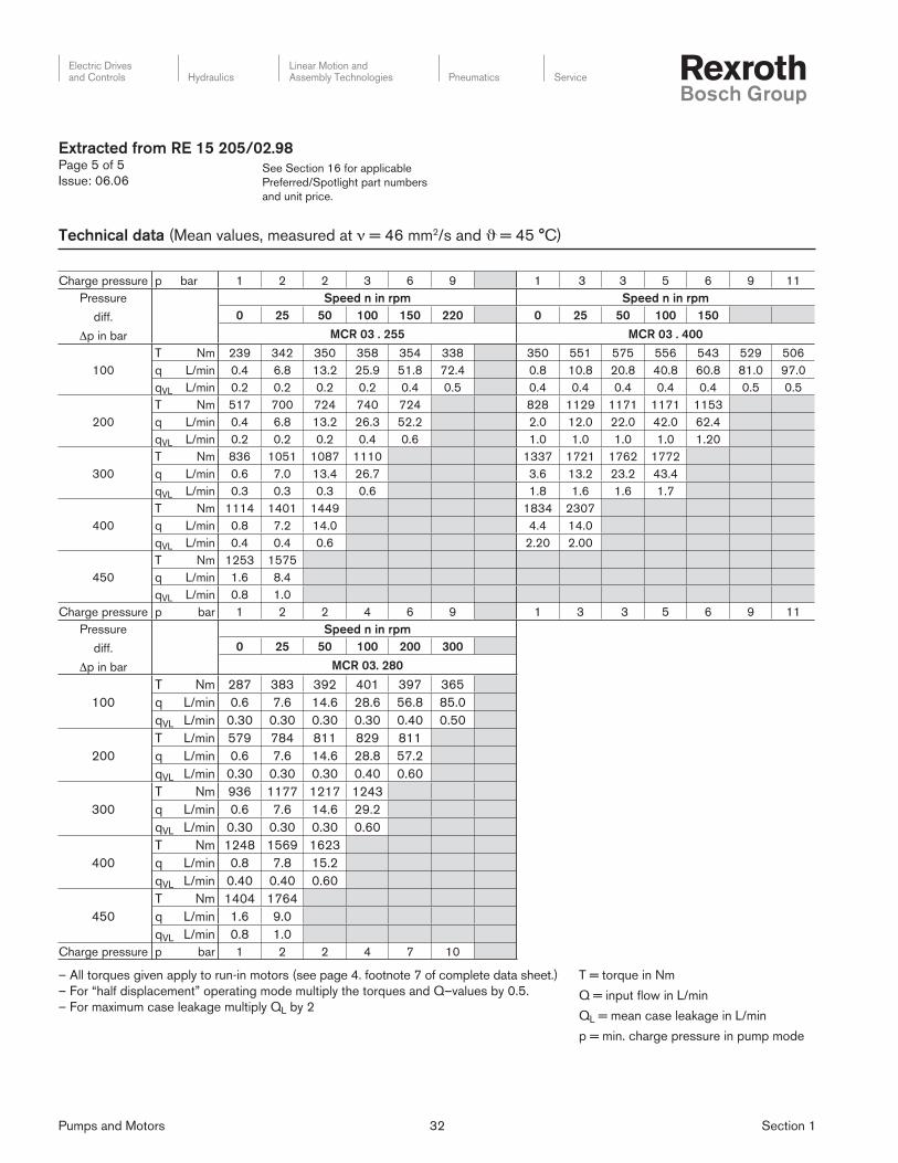
Technical data (Mean values, measured at ν = 46 mm2/s and ϑ = 45 °C)
Pumps and Motors 32 Section 1
Electric Drivesand Controls Hydraulics
Linear Motion andAssembly Technologies Pneumatics Service
See Section 16 for applicable
Preferred/Spotlight part numbers
and unit price.
Extracted from RE 15 205/02.98Page 5 of 5
Issue: 06.06
Technical data (Mean values, measured at ν = 46 mm2/s and ϑ = 45 °C)
Charge pressure p bar 1 2 2 3 6 9 1 3 3 5 6 9 11
Pressure
diff.
Δp in bar
Speed n in rpm Speed n in rpm
0 25 50 100 150 220 0 25 50 100 150
MCR 03 . 255 MCR 03 . 400
100
T Nm 239 342 350 358 354 338 350 551 575 556 543 529 506
q L/min 0.4 6.8 13.2 25.9 51.8 72.4 0.8 10.8 20.8 40.8 60.8 81.0 97.0
qVL L/min 0.2 0.2 0.2 0.2 0.4 0.5 0.4 0.4 0.4 0.4 0.4 0.5 0.5
200
T Nm 517 700 724 740 724 828 1129 1171 1171 1153
q L/min 0.4 6.8 13.2 26.3 52.2 2.0 12.0 22.0 42.0 62.4
qVL L/min 0.2 0.2 0.2 0.4 0.6 1.0 1.0 1.0 1.0 1.20
300
T Nm 836 1051 1087 1110 1337 1721 1762 1772
q L/min 0.6 7.0 13.4 26.7 3.6 13.2 23.2 43.4
qVL L/min 0.3 0.3 0.3 0.6 1.8 1.6 1.6 1.7
400
T Nm 1114 1401 1449 1834 2307
q L/min 0.8 7.2 14.0 4.4 14.0
qVL L/min 0.4 0.4 0.6 2.20 2.00
450
T Nm 1253 1575
q L/min 1.6 8.4
qVL L/min 0.8 1.0
Charge pressure p bar 1 2 2 4 6 9 1 3 3 5 6 9 11
Pressure
diff.
Δp in bar
Speed n in rpm
0 25 50 100 200 300
MCR 03. 280
100
T Nm 287 383 392 401 397 365
q L/min 0.6 7.6 14.6 28.6 56.8 85.0
qVL L/min 0.30 0.30 0.30 0.30 0.40 0.50
200
T L/min 579 784 811 829 811
q L/min 0.6 7.6 14.6 28.8 57.2
qVL L/min 0.30 0.30 0.30 0.40 0.60
300
T Nm 936 1177 1217 1243
q L/min 0.6 7.6 14.6 29.2
qVL L/min 0.30 0.30 0.30 0.60
400
T Nm 1248 1569 1623
q L/min 0.8 7.8 15.2
qVL L/min 0.40 0.40 0.60
450
T Nm 1404 1764
q L/min 1.6 9.0
qVL L/min 0.8 1.0
Charge pressure p bar 1 2 2 4 7 10
– All torques given apply to run-in motors (see page 4. footnote 7 of complete data sheet.)
– For “half displacement” operating mode multiply the torques and Q–values by 0.5.
– For maximum case leakage multiply QL by 2
T = torque in Nm
Q = input flow in L/min
QL = mean case leakage in L/min
p = min. charge pressure in pump mode

Pumps and Motors 33 Section 1
Electric Drivesand Controls Hydraulics
Linear Motion andAssembly Technologies Pneumatics Service
See Section 16 for applicable
Preferred/Spotlight part numbers
and unit price.
Extracted from RE 15 206/02.98Page 1 of 4
Issue: 06.06
Hydraulic motor
Radial piston, low speed, high torque
Model MCR 05
Sizes 380 to 820
Series 3X
Maximum operating pressure 6500 psi (450 bar)
Maximum displacement volume 50 in3 (820 cm3)
Maximum output torque 3573 lb-ft (4844 Nm)
– Compact, sturdy construction
– Smooth running even at very low speeds
– Low noise
– Reversible
– Sealed taper roller bearings
– High radial forces permitted on the output shaft
– Shaft seal up to 10 bar
– Freewheeling
– Available with optional built-on holding (multi-disc) brake
or dynamic (drum) brake
Function
Closed circuit
Minimum inlet pressure must be adapted to suit operating condi-
tions; the following must be taken into consideration:
Idling pressure. flow resistances. pump operation.
Minimum flow of the feed pump must be adapted to suit operating
conditions.
Open circuit
Minimum inlet pressure must be adapted to suit operating condi-
tions; the following must be taken into consideration:
Idling pressure. flow resistances. pump operation.
The outlet pressure must be at least 2 bar greater than the pres-
sure in the housing.
Note: If the motor circuits are in series please consult the
manufacturer.
Model MCR 05 C...F180Z-3X/B4M/..
Pumps and Motors 34 Section 1
Electric Drivesand Controls Hydraulics
Linear Motion andAssembly Technologies Pneumatics Service
See Section 16 for applicable
Preferred/Spotlight part numbers
and unit price.
Extracted from RE 15 206/02.98Page 2 of 4
Issue: 06.06
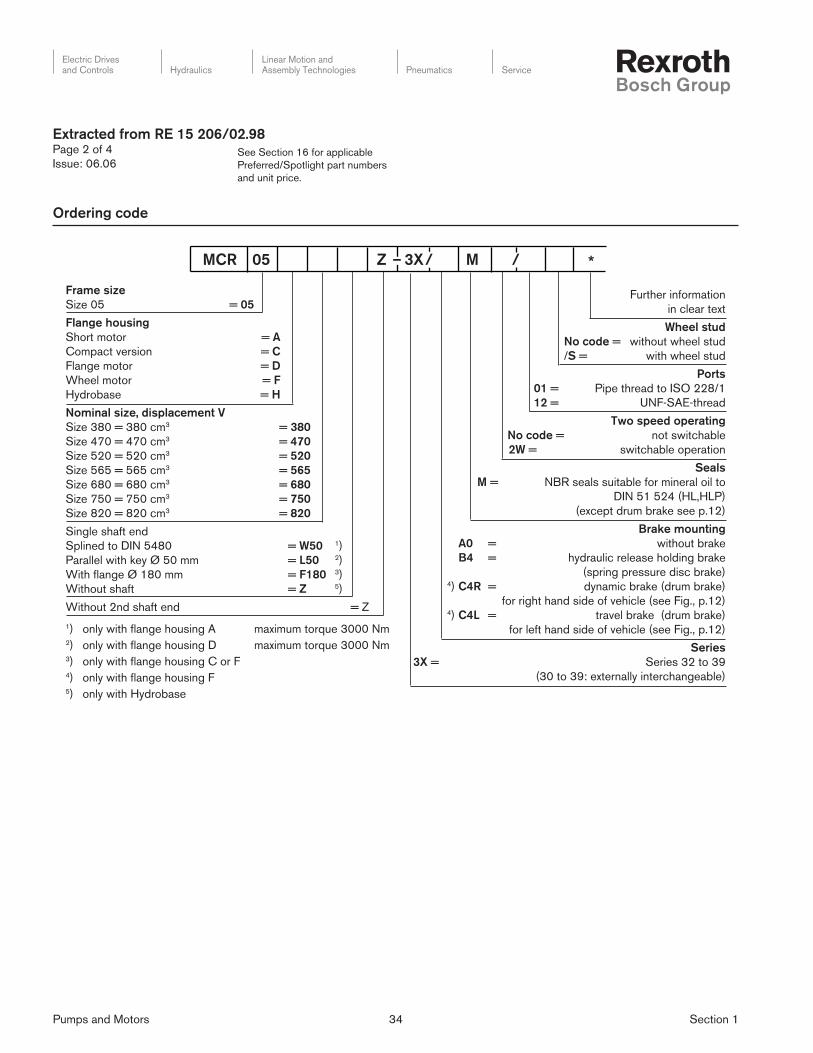
Ordering code
Further information
in clear text
Wheel stud
No code = without wheel stud
/S = with wheel stud
Ports
01 = Pipe thread to ISO 228/1
12 = UNF-SAE-thread
Two speed operating
No code = not switchable
2W = switchable operation
Seals
M = NBR seals suitable for mineral oil to
DIN 51 524 (HL,HLP)
(except drum brake see p.12)
Brake mounting
A0 = without brake
B4 = hydraulic release holding brake
(spring pressure disc brake) 4) C4R = dynamic brake (drum brake)
for right hand side of vehicle (see Fig., p.12) 4) C4L = travel brake (drum brake)
for left hand side of vehicle (see Fig., p.12)
Series
3X = Series 32 to 39
(30 to 39: externally interchangeable)
MCR 05 Z – 3X / M / *
Frame size
Size 05 = 05
Flange housing
Short motor = A
Compact version = C
Flange motor = D
Wheel motor = F
Hydrobase = H
Nominal size, displacement V
Size 380 = 380 cm3 = 380
Size 470 = 470 cm3 = 470
Size 520 = 520 cm3 = 520
Size 565 = 565 cm3 = 565
Size 680 = 680 cm3 = 680
Size 750 = 750 cm3 = 750
Size 820 = 820 cm3 = 820
Single shaft end
Splined to DIN 5480 = W50 1)
Parallel with key Ø 50 mm = L50 2)
With flange Ø 180 mm = F180 3)
Without shaft = Z 5)
Without 2nd shaft end = Z
1) only with flange housing A maximum torque 3000 Nm 2) only with flange housing D maximum torque 3000 Nm 3) only with flange housing C or F4) only with flange housing F5) only with Hydrobase

Pumps and Motors 35 Section 1
Electric Drivesand Controls Hydraulics
Linear Motion andAssembly Technologies Pneumatics Service
See Section 16 for applicable
Preferred/Spotlight part numbers
and unit price.
1) The data given apply after 100 hours running-in time
2) Continuous operation
3) Peak values may occur for a maximum duration of one second
within an operating minute.
4) In the return line we recommend pmin = 15 bar
5) Environmentally friendly fl uids HETG. HEPG. HEE to RE 90 221
6) For connection in series. consult the technical sales department.
7) Warning! During the running-in time of the motor (min. 20
hours) motors should not be run unloaded at greater than 50% of
maximum speed.
Radial piston multi-disc motor with fi xed displacement
Frame size MCR 05...
Type of mounting Flange mounting; face mounting
Pipe connections Threaded or fl anged
Mounting position optional
Shaft loading see page 7
Direction of rotation Right/left - reversible
Frame size 05
Nominal size 380 470 520 565 680 750 820
Displacement V cm3 380 470 520 565 680 750 820
Flow at n = 100 rpm/100 bar qV L/min 38 47 52 56.5 70 77 84
Output torque 1; 7)
T Nm 604 748 827 899 1082 1194 1305– specifi c torque (at Δp = 100 bar)
– peak torque T Nm 2528 3127 3459 3759 4017 4430 4844
Output speed 1; 7)
– min. speed n rpm 5 to 10 when running smoothly, dependent on application
– max. speed n rpm 220 220 220 220 200 170 150
– freewheeling speed n rpm 600
Output power 1; 7)
– cont. power at full displacenent P kW 29 29 29 29 35 35 35
– cont. power at half displacement P kW 19 19 19 19 23 23 23
Weight m kg see unit dimensions pages 8 to 12
Polar moment of inertia Jm kgmm2 see unit dimensions pages 8 to 12
Hydraulic
Nominal pressure p bar 250
Pressure differential, cont. 2; 3) Δp
bar 250– with mineral oil (HL, HLP)
Pressure differential, peak 4; 3) Δp
bar 450 400– with mineral oil (HL, HLP)
Inlet pressure Port “A” or “B” p bar 470 420
Summated pressure 5; 3) ports “A” + “B” p bar 470 420
Case drain pressure,max p bar 10
Hydraulic fl uid 6) Mineral oils (HL, HLP) to DIN 51 524
Hydraulic fl uid temperature range ϑ °C – 20 to +80
Viscosity range ν mm2/s 10 to 2000
Fluid cleanliness Maximum degree of contamination of the fl uid to NAS 1638
class 9. We therefore recommend a fi lter with a minimum
retention rate of ß10 ≥ 75.
Brake
Holding brake (disc brake) B2 B4
Holding torque T Nm 2200 5000
Release pressure, min – max p bar 15 – 30 15 – 30
Volume to operate brake V cm3 23 46
Technical data (For applications outside these parameters please consult us!)
Extracted from RE 15 206/02.98Page 3 of 4
Issue: 06.06

Pumps and Motors 36 Section 1
Electric Drivesand Controls Hydraulics
Linear Motion andAssembly Technologies Pneumatics Service
– All torques given apply to run-in motors (see page 4. footnote 7 of complete data sheet.)
– For “half displacement” operating mode multiply the torques and Q–values by 0.5.
– For maximum case leakage multiply QL by 2
T = torque in Nm
Q = input flow in L/min
QL = mean case leakage in L/min
Pressure
diff.
Δp in bar
Speed n in rpm Speed n in rpm
0 25 50 100 150 220 0 25 50 100 150 220
MCR 05 . 380 MCR 05. 680
100
T Nm 393 513 538 544 525 507 5.95 989 995 908 821 698
qV L/min 0.3 9.8 19.3 38.6 57.7 84.4 0.88 17.64 34.93 70.01 102.76 139.54
qV L L/min 0.15 0.15 0.15 0.30 0.35 0.40 0.44 0.47 0.50 0.57 0.64 0.64
200
T Nm 846 1075 1123 1111 1087 1407 1938 2017 1973 1862
qV L/min 0.7 10.2 19.7 38.9 58.0 2.4 18.55 36.09 72.17 103.61
qVL L/min 0.35 0.35 0.35 0.45 0.50 1.20 1.22 1.24 1.30 1.41
300
T Nm 1268 1613 1685 1667 2338 2964 3026 3013
qV L/min 0.9 10.4 19.9 39.2 3.7 19.24 36.82 71.98
qVL L/min 0.45 0.45 0.45 0.60 1.85 1.91 1.97 2.14
400
T Nm 1691 2150 2247 3116 3939 4017
qV L/min 1.5 11.0 20.5 4.34 19.91 38.18
qVL L/min 0.75 0.75 0.75 2.17 2.35 2.33
450
T Nm 1903 2419 2528
qV L/min 2.2 11.7 21.2
qVL L/min 1.1 1.1 1.1
Charge pressure p bar 1 4 4 6 9 14 1 2 3 7 12 23
Speed n rpm 0 25 50 100 150 220 0 25 50 100 150
MCR 05 . 470 MCR 05 . 750
100
T Nm 484 632 662 670 647 625 657 1091 1098 1002 906
qV L/min 0.40 12.2 23.9 47.8 71.5 105.0 0.88 19.39 38.43 77.01 113.26
qV L L/min 0.20 0.20 0.20 0.40 0.50 0.80 0.44 0.47 0.50 0.57 0.64
200
T L/min 1042 1324 1384 1369 1339 1551 2137 2224 2176
qV L/min 0.80 12.6 24.3 48.2 71.9 2.40 20.30 39.59 79.17
qV L L/min 0.40 0.40 0.40 0.60 0.70 1.20 1.22 1.24 1.30
300
T Nm 1562 1986 2076 2053 2578 3270 3338
qV L/min 1.2 13.0 24.7 48.6 3.7 20.99 40.32
qV L L/min 0.60 0.60 0.60 0.80 1.85 1.91 1.97
400
T Nm 2083 2649 2768 3438 4345 4430
qV L/min 2.0 13.8 25.5 4.34 21.66 41.73
qV L L/min 1.0 1.0 1.0 2.17 2.35 2.37
450
T Nm 2344 2980 3114
qV L/min 3.0 14.8 26.5
qV L L/min 1.5 1.5 1.5
Charge pressure p bar 1 5 5 7 10 16 1 3 4 9 15
Speed n min-1 0 25 50 100 150 220 0 25 50 100 150
MCR 05 . 520 MCR 05 . 820
100
T Nm 538 702 737 744 683 620 718 1192 1200 1095 990
qV L/min 0.4 13.4 26.4 52.8 79.0 116.0 0.88 21.14 41.93 84.01 123.76
qV L L/min 0.20 0.20 0.20 0.40 0.50 0.80 0.44 0.47 0.50 0.57 0.64
200
T Nm 1158 1472 1537 1520 1487 1697 2337 2432 2380
qV L/min 0.80 13.8 26.8 53.2 79.4 2.40 22.05 43.09 86.17
qV L L/min 0.40 0.40 0.40 0.60 0.70 1.20 1.22 1.24 1.30
300
T Nm 1735 2207 2305 2281 2819 3573 3649
qV L/min 1.2 14.2 27.2 53.6 3.70 22.74 43.82
qV L L/min 0.60 0.60 0.60 0.80 1.85 1.91 1.97
400
T Nm 2314 2942 3074 3758 4750 4844
qV L/min 2.0 15.0 28.0 4.34 23.35 45.18
qVL L/min 1.00 1.00 1.00 2.17 2.35 2.37
450
T Nm 2604 3310 3459
qV L/min 3.0 16.0 29.0
qV L L/min 1.5 1.5 1.5
Charge pressure p bar 1 6 6 7 11 17 1 4 6 11 19
Technical data (Mean values, measured at ν = 46 mm2/s and ϑ = 45 °C)

Pumps and Motors 37 Section 1
Electric Drivesand Controls Hydraulics
Linear Motion andAssembly Technologies Pneumatics Service
See Section 16 for applicable
Preferred/Spotlight part numbers
and unit price.
Extracted from RE 15 207/02.98Page 1 of 4
Issue: 06.06
Hydraulic motor
Radial piston, low speed, high torque
Model MCR 10
Sizes 780 to 1340
Series 3X
Maximum operating pressure 6500 psi (450 bar)
Maximum displacement volume 81.8 in3 (1340 cm3)
Maximum output torque 5920 lb-ft (8027 Nm)
– Compact, robust construction
– Smooth running even at very low speeds
– Low noise
– Reversible
– Sealed taper roller bearings
– High radial forces permitted on the output shaft
– Shaft seal up to 10 bar
– Available with optional built-on holding (multi-disc)
brake or dynamic (drum) brake
– switchable
• free-running
• half displacement volume
– for open and closed circuit operation
Function
Closed circuit
Minimum inlet pressure must be adapted to suit operating condi-
tions; the following must be taken into consideration:
Idling pressure. flow resistances. pump operation.
Minimum flow of the feed pump must be adapted to suit operating
conditions.
Open circuit
Minimum inlet pressure must be adapted to suit operating condi-
tions; the following must be taken into consideration:
Idling pressure. flow resistances. pump operation.
The outlet pressure must be at least 2 bar greater than the pres-
sure in the housing.
Note: If the motor circuits are in series please consult the
manufacturer.
Model MCR 10 F...F250Z-3X/B7M...
Model MCR 10 F...F250Z-3X/C7.M...
Model MCR 10 F...F250Z-3X/A0M...

Pumps and Motors 38 Section 1
Electric Drivesand Controls Hydraulics
Linear Motion andAssembly Technologies Pneumatics Service
See Section 16 for applicable
Preferred/Spotlight part numbers
and unit price.
Extracted from RE 15 207/02.98Page 2 of 4
Issue: 06.06
Ordering code
Frame size
Frame size 10 = 10
Flange housing
Short motor = C
Wheel motor = F
Flange motor = D
Size/displacement volume V
Size 780 = 780 cm3 = 780
Size 940 = 940 cm3 = 940
Size 1120 = 1120 cm3 = 1120
Size 1250 = 1250 cm3 = 1250
Size 1340 = 1340 cm3 = 1340
Single shaft end
With flange Ø 250 = F250 1)
Parallel with key Ø 60 = L60 2; 3)
Without 2nd shaft end = Z
Series nos.
Series 30 to 39 = 3X
(30 to 39, externally interchangeable)
1) Only with flange housing C or F2) Only with flange housing D3) Max. permitted pressure differential Δp = 250 bar
4) Only with flange housing F
MCR 10 Z – 3X M * Further details
in clear text
Studs
No code = without studs
/S = with studs for
wheel mounting
Connections
/11 = Pipe thread to ISO 228/1
/42 = UNF-SAE-thread
Switchable displacement
No code = not switchable
2W = switchable operation
Seals
M = NBR seals suitable for
mineral oil to DIN 51 524 (HL, HLP)
Brake mounting
A0 = no brake
B7 = hydraulically released holding brake
(spring pressure disc brake) 4) C7R = travel brake (drum brake)
for right hand side of vehicle, see fig., p. 9 4) C7L = travel brake (drum brake)
for left hand side of vehicle, see fig., p. 9

Pumps and Motors 39 Section 1
Electric Drivesand Controls Hydraulics
Linear Motion andAssembly Technologies Pneumatics Service
See Section 16 for applicable
Preferred/Spotlight part numbers
and unit price.
1) The data given apply after 100 hours running-in time2) Continuous operation3) Peak values may occur for a maximum duration of one second
within an operating minute.4) In the return line we recommend pmin = 15 bar5) Environmentally friendly fl uids HETG. HEPG. HEE to RE 90 221
Description Radial piston multi-disc motor, switchable displacement
Model description MCR 10...
Type of mounting Flange mounting; face mounting
Connections Threaded or fl anged
Mounting position Optional
Shaft loading See page 6
Rotation clockwise/anti-clockwise - reversible
Frame size 10
Size 780 940 1120 1250 1340
Displacement V cm3 780 940 1120 1250 1340
Flow n = 100 rpm/100 bar qV L/min 79 95 113.5 126.5 136.5
Output torque 1; 7)
T Nm 1240 1494 1783 1990 2130– specifi c torque (at Δp = 100 bar)
– peak torque T Nm 5134 6187 6659 7432 8027
Output speed 1; 7)
n rpm 5 to 10 for smooth running, depending on application– min. speed
– max. speed n rpm 170 150 150 140 120
– freewheeling speed n rpm 400
Output power 1; 7)
– continuous power P kW 44 44 50 50 50
Weight – motor m kg 69
– motor with holding brake m kg 81
– motor with travel brake m kg 92
Hydraulic
Nominal pressure p bar 250
Pressure differential, cont. 2; 6; 7; 8) Δp
bar 250– for mineral oil (HL, HLP)
Pressure differential, peak 3; 6; 7; 8) Δp
bar 450 400–for mineral oil (HL, HLP)
Inlet pressure 6) Port “A” or “B” p bar 470 420
Summated pressure 4; 6) Port “A” + “B” p bar 470 420
Case drain pressure, max. pmax bar 10
Switching pressure (displacement switching) bar 10 to 30
Hydraulic fl uid 5) Mineral oil (HL, HLP) to DIN 51 524
Hydraulic fl uid temperature range ϑ °C – 20 to +80
Viscosity range ν mm2/s 10 to 2000
Fluid cleanliness: Maximum permissible degree of contamination of fl uid to
NAS 1638 Class 9. We therefore recommend a fi lter with
a minimum retention rate of ß10 ≥ 75.
Brake Holding brake (disc brake)
Holding torque T Nm 7000
Release pressure p bar min. 15; max. 30
Technical data (For applications outside these parameters please consult us)
Extracted from RE 15 207/02.98Page 3 of 4
Issue: 06.06
6) For connection in series. consult the technical sales department.7) Warning! During the running-in time of the motor (min. 20 hours)
motors should not be run unloaded at greater than 50% of
maximum speed.8) For single shaft end “L60” max. permissible pressure differential
Δp = 250 bar

Pumps and Motors 40 Section 1
Electric Drivesand Controls Hydraulics
Linear Motion andAssembly Technologies Pneumatics Service
See Section 16 for applicable
Preferred/Spotlight part numbers
and unit price.
Nominal Size 780 1250
Speed n in rev/min 0 25 50 100 150 0 25 50 100 150
100
T Nm 806 994 1049 1029 911 1094 1818 1726 1517 1309
qV L/min 0.3 19.8 39.47 79.00 118.20 1.00 32.09 63.73 126.69 189.30
qVL L/min 0.15 0.15 0.24 0.50 0.60 0.50 0.56 0.63 0.76 0.90
200
T Nm 1736 2232 2282 2232 2158 2586 3669 3684 3497
qV L/min 0.60 20.10 39.80 79.50 118.8 2.86 33.03 64.63 127.82
qVL L/min 0.30 0.30 0.40 0.75 0.9 1.43 1.44 1.45 1.46
300
T Nm 2604 3348 3422 3348 4178 5550 5574
qV L/min 0.80 20.30 40.00 80.00 4.08 34.08 66.16
qVL L/min 0.40 0.40 0.50 1.00 2.04 2.10 2.16
400
T Nm 3472 4464 4563 5730 7432 7416
qV L/min 1.40 20.90 40.80 5.68 35.11 67.35
qVL L/min 0.70 0.70 0.90 2.84 2.92 3.00
450
T Nm 3906 5022 5134
qV L/min 1.6 21.10 41.00
qVL L/min 0.8 0.8 1.00
Nominal Size 940 1340
Speed n in rev/min 0 25 50 100 150 0 25 50 100
100
T Nm 971 1198 1264 1240 1098 1182 1964 1865 1639
qV L/min 1.00 23.80 47.47 95.00 142.20 1.00 34.61 68.78 136.76
qVL L/min 0.15 0.15 0.24 0.50 0.60 0.50 0.56 0.63 0.76
200
T L/min 2091 2690 2750 2689 2793 3962 3979 3777
qV L/min 0.60 24.10 47.80 95.50 2.86 35.56 69.68 137.93
qVL L/min 0.30 0.30 0.40 0.75 1.43 1.44 1.45 1.46
300
T Nm 3137 4035 4124 4512 5994 6020
qV L/min 0.80 24.30 48.00 4.08 36.64 71.24
qVL L/min 0.40 0.40 0.50 2.04 2.10 2.16
400
T Nm 4183 5380 5500 6188 8027 8010
qV L/min 1.40 24.90 48.80 5.68 37.67 72.50
qVL L/min 0.70 0.70 0.90 2.84 2.92 3.00
450
T Nm 4706 6052 6187
qV L/min 1.60 25.10 49.00
qVL L/min 0.80 0.80 1.00
Nominal Size 1120
Speed n in rev/min 0 25 50 100 150
100
T Nm 980 1629 1547 1360 1173
qV L/min 1.00 28.82 57.19 113.62 169.80
qVL L/min 0.50 0.56 0.63 0.76 0.90
200
T Nm 2317 3287 3301 3134
qV L/min 2.86 29.76 58.07 114.71
qVL L/min 1.43 1.44 1.45 1.46
300
T Nm 3743 4973 4994
qV L/min 4.08 30.76 59.49
qVL L/min 2.04 2.10 2.16
400
T Nm 5134 6660 6645
qV L/min 5.68 31.76 60.87
qVL L/min 2.84 2.92 3.00
Notes on the technical data
T = torque in Nm
Q = input flow in L/min
QL = mean case leakage in L/min
Extracted from RE 15 207/02.98Page 4 of 4
Issue: 06.06
Technical data (Mean values, measured at ν = 46 mm2/s and ϑ = 45 °C)
– All torques given apply to run-in motors
(see page 4. footnote 7 of complete data sheet.)
– For “half displacement” operating mode
multiply the torques and Q–values by 0.5.
– For maximum case leakage multiply QL by 2

Pumps and Motors 41 Section 1
Electric Drivesand Controls Hydraulics
Linear Motion andAssembly Technologies Pneumatics Service
See Section 16 for applicable
Preferred/Spotlight part numbers
and unit price.
Flange housing
Wheel version = F
Sizes/Displacement V
Size 1130 = 1130 cm3 = 1130
Size 1250 = 1250 cm3 = 1250
Size 1500 = 1500 cm3 = 1500
Size 1780 = 1780 cm3 = 1780
Size 2150 = 2150 cm3 = 2150
1st shaft end
with flange 280 = F 280
without 2nd shaft end = Z
Series = 3X
Series 30 to 39
(30 to 39. externally interchangeable)
Extracted from RE 15 208/10.94Page 1 of 3
Issue: 06.06
Hydraulic motor
Radial piston, low speed, high torque
Model MCR 15
Sizes 1130 to 2150
Series 3X
Maximum operating pressure 6500 psi (450 bar)
Maximum displacement volume 131 in3 (2150 cm3)
Maximum output torque 10096 lb-ft (13688 Nm)
– compact. sturdy construction
– smooth running even at very low speeds
– low noise
– reversible
– sealed tapered roller bearing
– high radial forces permitted on output shaft
– shaft seal up to 10 bar
– optional integral holding brake (multi-disc brake) or wheel brake
(drum brake)
– switchable
• freewheeling
• half displacement
– for open and closed circuits
Ordering code
MCR 15 Z – 3X M *
Further details
in clear text
Studs
no code = without studs
/S = with studs for
wheel mounting
Ports
11 = BSP thread to ISO 228/1
42 = UNF-SAE threads
no code = not switchable.
anti-clockwise rotation preferred
2R = switchable. clockw. rotation preferred
2L = switchable. anti-clw. rotation preferred
Seals
M = NBR seals. suitable for
mineral oil to DIN 51 524 (HL. HLP)
Brake mounting
AO = without brake
B11 = hydraulic holding brake
(spring pressure disc brake)
Function
Closed circuit
Minimum inlet pressure must be adapted to suit operating condi-
tions; the following must be taken into consideration:
Idling pressure. flow resistances. pump operation.
Min. flow of the pump must be adapted to suit operating conditions.
Open circuit
Minimum inlet pressure must be adapted to suit operating condi-
tions; the following must be taken into consideration:
Idling pressure. flow resistances. pump operation.
The outlet pressure must be at least 2 bar greater than the pres-
sure in the housing.
Note: If the motor circuits are in series please consult the
manufacturer.

Pumps and Motors 42 Section 1
Electric Drivesand Controls Hydraulics
Linear Motion andAssembly Technologies Pneumatics Service
See Section 16 for applicable
Preferred/Spotlight part numbers
and unit price.
1) The data given apply after 100 hours running-in time2) Continuous operation3) Peak values may occur for a maximum duration of one second
within an operating minute.4) In the return line we recommend pmin = 15 bar
Type Piston machine
Model Radial piston multi-stroke motor, switchable displacement
Type code MCR 15...
Type of mounting Flange mounting; face mounting
Type of connection Threaded, fl ange
Mounting position Optional
Shaft load See pages 6, 7
Direction of rotation Right / left - reversible
Frame size 15
Nominal size 1130 1250 1500 1780 2150
Displacement V cm3 1130 1250 1500 1780 2150
Displacement fl ow at n = 100 rev/min/100 bar Q L/min 114 126 151 179 216
Output torque 1), 7)
– spec. torque (at Δp = 100 bar) T Nm 1799 1990 2388 2833 3422
– max. torque T Nm 8095 8955 9552 11332 13688
Output torque 1; 7)
– min. speed n rev/min 5 to 10 when running smooth, depending on application
– max. speed n rev/min 150 150 150 125 125
– freewheeling n rev/min 300
Output power 1)
– continuous power P kW 55 55 55 60 60
Weight
– motor m kg 93
– motor with holding brake m kg 120
– motor with wheel brake m kg 135
Hydraulic
Nominal pressure p bar 250
Pressure difference, cont. 2), 6), 7) Δp
– with mineral oil (HL, HLP) bar 250
Pressure difference, peak 3), 6), 7) Δp
– with mineral oil (HL, HLP) bar 450 400
Inlet pressure port “A” or “B” p bar 470 420
Summated pressure 4; 6) port “A” + “B” p bar 470 420
Case drain pressure p bar 10
Fluid 5) Mineral oil (HL, HLP) to DIN 51 524
Fluid temperature range ϑ °C – 20 to +80
Viscosity range ν mm2/s 10 to 2000
Fluid cleanliness Max. permissible degree of contamination of the fl uid to NAS
1638 class 9. We therefore recommend a fi lter with a minimum
retention rate of ß10 ≥ 75.
Brake
Holding brake (multi-disc brake)
Holding torque T Nm 11 000
Brake release pressure, min – max p bar Min. 15 max. 30
Wheel brake (drum brake) See table page 8
Technical data (For applications outside these parameters please consult us)
Extracted from RE 15 208/10.94Page 2 of 3
Issue: 06.06
5) Environmentally friendly fl uids HETG. HEPG. HEE to RE 90 2216) For connection in series. consult the technical sales department.7) Warning! During the running-in time of the motor (min. 20
hours) motors should not be run unloaded at greater than 50% of maximum speed.

Pumps and Motors 43 Section 1
Electric Drivesand Controls Hydraulics
Linear Motion andAssembly Technologies Pneumatics Service
See Section 16 for applicable
Preferred/Spotlight part numbers
and unit price.
Nominal Size 1130 1780
Speed n in rev/min 0 25 50 100 150 0 25 50 100 150
100
T Nm 1133 1529 1583 1493 1397 1558 2456 2420 2043
Q L/min 0.72 28.95 57.40 114.19 171.31 0.74 45.41 90.05 179.22
QL L/min 0.20 0.20 0.30 0.50 0.90 0.37 0.41 0.45 0.53
200
T Nm 2447 3166 3238 3166 3133 3683 5049 5116 4833
Q L/min 2.18 29.59 58.09 114.98 172.16 2.18 46.55 91.22 180.55
QL L/min 0.40 0.40 0.50 0.60 1.00 1.09 1.11 1.13 1.17
300
T Nm 3670 4749 4858 4694 5949 7692 7794
Q L/min 4.04 30.10 59.02 115.52 4.04 48.00 93.10
QL L/min 0.50 0.50 0.70 0.70 2.02 2.15 2.28
400
T Nm 4892 6331 6474 8160 10335 10425
Q L/min 5.84 31.00 59.81 5.82 49.46 94.81
QL L/min 1.00 1.00 1.00 2.92 3.21 3.50
450
T Nm 5503 7122 7284
Q L/min 6.90 31.46 60.59
QL L/min 1.10 1.10 1.30
Nominal Size 1250 2150
Speed n in rev/min 0 25 50 100 150 0 25 50 100
100
T Nm 1253 1692 1751 1691 1512 1882 2967 2922 2467
Q L/min 0.74 31.95 63.40 126.19 189.31 0.72 54.66 108.55 216.22
QL L/min 0.20 0.20 0.30 0.50 0.90 0.37 0.41 0.45 0.53
200
T Nm 2707 3503 3582 3503 4448 6098 6180
Q L/min 2.18 32.59 64.09 126.98 2.18 55.80 109.72
QL L/min 0.40 0.40 0.50 0.60 1.09 1.11 1.13
300
T Nm 4060 5254 5373 7186 9290 9414
Q L/min 4.04 33.10 65.02 4.04 57.25 111.60
QL L/min 0.50 0.50 0.70 2.02 2.15 2.28
400
T Nm 5411 7003 7162 9855 12483
Q L/min 5.82 34.00 65.81 5.84 58.71
QL L/min 1.00 1.00 1.00 2.92 3.21
450
T Nm 6088 7878 8057
Q L/min 6.90 34.46 66.59
QL L/min 1.10 1.10 1.30
Nominal Size 1500
Speed n in rev/min 0 25 50 100 150
100
T Nm 1504 2030 2101 1983 1719
Q L/min 0.40 37.90 75.60 151.00 226.80
QL L/min 0.20 0.20 0.30 0.50 0.90
200
T Nm 3248 4203 4298 4203
Q L/min 0.80 38.30 76.00 151.20
QL L/min 0.40 0.40 0.50 0.60
300
T Nm 4872 6304 6448
Q L/min 1.00 38.50 76.40
QL L/min 0.50 0.50 0.70
400
T Nm 6494 8403 8594
Q L/min 2.00 39.50 77.40
QL L/min 1.00 1.00 1.00
450
T Nm 7305 9454 9669
Q L/min 2.20 39.70 77.60
QL L/min 1.10 1.10 1.30
Technical data (Mean values, measured at ν = 46 mm2/s and ϑ = 45 °C)
Extracted from RE 15 208/10.94Page 3 of 3
Issue: 06.06
Notes on the technical data
T = torque in Nm
Q = input flow in L/min
QL = mean case leakage in L/min
– All torques given apply to run-in motors
(see page 4. footnote 7 of complete data sheet.)
– For “half displacement” operating mode
multiply the torques and Q–values by 0.5.
– For maximum case leakage multiply QL by 2

Pumps and Motors 44 Section 1
Electric Drivesand Controls Hydraulics
Linear Motion andAssembly Technologies Pneumatics Service
See Section 16 for applicable
Preferred/Spotlight part numbers
and unit price.
Extracted from RE 15 209/03.95Page 1 of 3
Issue: 06.06
Hydraulic motor
Radial piston, low speed, high torque
Model MCR 20
Sizes 1750 to 3000
Series 3X
Maximum operating pressure 6500 psi (450 bar)
Maximum displacement volume 183 in3 (3000 cm3)
Maximum output torque 12570 lb-ft (17043 Nm)
– compact, sturdy construction
– smooth running even at very low speeds
– low noise
– reversible
– sealed tapered roller bearing
– high radial forces permitted on output shaft
– shaft seal up to 10 bar
– optional integral holding brake (multi-disc brake)
– switchable
• freewheeling
• half displacement
– for open and closed circuits
Ordering code
Sizes/Displacement V
Size 1750 = 1750 cm3 = 1750
Size 2100 = 2100 cm3 = 2100
Size 2500 = 2500 cm3 = 2500
Size 3000 = 3000 cm3 = 3000
1st shaft end
with flange 280 = F 280
without 2nd shaft end = Z
Series
Series 30 to 39 = 3X
(30 to 39, externally interchangeable)
MCR 20 C Z – 3X M * Further details
in clear text
Studs
no code = without studs
/S = with studs for
wheel mounting
Ports
11 = BSP thread to ISO 228/1
42 = UNF-SAE threads
no code = not switchable,
2W = switchable displacement
Seals
M = NBR seals, suitable for
mineral oil to DIN 51 524 (HL, HLP)
Brake mounting
AO = without brake
B19 = hydraulic holding brake
(spring pressure disc brake)
Function
Closed circuit
Minimum inlet pressure must be adapted to suit operating condi-
tions; the following must be taken into consideration:
Idling pressure. flow resistances. pump operation.
Min. flow of the pump must be adapted to suit operating conditions.
Open circuit
Minimum inlet pressure must be adapted to suit operating condi-
tions; the following must be taken into consideration:
Idling pressure. flow resistances. pump operation.
The outlet pressure must be at least 2 bar greater than the pres-
sure in the housing. Note: If the motor circuits are in series
please consult the manufacturer.

Pumps and Motors 45 Section 1
Electric Drivesand Controls Hydraulics
Linear Motion andAssembly Technologies Pneumatics Service
See Section 16 for applicable
Preferred/Spotlight part numbers
and unit price.
Type Piston machine
Model Radial piston multi-stroke motor, switchable displacement
Type code MCR 20...
Type of mounting Flange mounting; face mounting
Type of connection Threaded, fl ange
Mounting position Optional
Shaft load See page 6
Direction of rotation Right / left - reversible
Frame size 20
Nominal size 1750 2100 2500 3000
Displacement V cm3 1750 2100 2500 3000
Displacement fl ow at n = 100 rev/min/100 bar Q L/min 176 211 252 302
Output torque 1), 7)
– spec. torque (at Δp = 100 bar) T Nm 2785 3342 3979 4775
– max. torque T Nm 11 531 13 762 14 244 17 093
Output speed
– min. speed n rev/min 5 to 10 when running smoothly, depending on application
– max. continious speed n rev/min 125 125 115 115
– max. intermitent speed n rev/min 160 160 115 115
– freewheeling n rev/min 500
Output power 1)
Weight – continuous power P kW 70 70 85 85
– motor m kg 110
– motor with holding brake m kg 140
Hydraulic
Nominal pressure p bar 250
Pressure difference, cont. 2), 6), 7) Δp
– with mineral oil (HL, HLP) bar 250
Pressure difference, peak 3), 6), 7) Δp
– with mineral oil (HL, HLP) bar 450 400
Inlet pressure port “A” or “B” p bar 470 420
Summated pressure 4; 6) port “A” + “B” p bar 470 420
Case drain pressure p bar 10
Fluid 5) Mineral oil (HL, HLP) to DIN 51 524
Fluid temperature range ϑ °C – 20 to +80
Viscosity range ν mm2/s 10 to 2000
Fluid cleanliness Max. permissible degree of contamination of the fl uid to
NAS 1638 class 9. We therefore recommend a fi lter with
a minimum retention rate of ß10 ≥ 75.
Brake
Holding brake (multi-disc brake)
Holding torque T Nm 19 000
Brake release pressure, min – max p bar Min. 15 Max. 30
1) The data given apply after 100 hours running-in time2) Continuous operation3) Peak values may occur for a maximum duration of one second
within an operating minute.4) In the return line we recommend pmin = 15 bar5) Environmentally friendly fl uids HETG, HEPG, HEE to RE 90 221
Technical data (For applications outside these parameters please consult us)
6) For connection in series, consult the technical sales department.7) Warning! During the running-in time of the motor (min. 20
hours) motors should not be run unloaded at greater than 50% of maximum speed.
Extracted from RE 15 209/03.95Page 2 of 3
Issue: 06.06

Pumps and Motors 46 Section 1
Electric Drivesand Controls Hydraulics
Linear Motion andAssembly Technologies Pneumatics Service
See Section 16 for applicable
Preferred/Spotlight part numbers
and unit price.
Technical data (Mean values, measured at ν = 46 mm2/s and ϑ = 45 °C)
Pressure
Differential
Δp bar
Speed in RPM Speed in RPM
0 25 50 100 125 0 25 50 100 115
MCR20. 1750 MCR20. 3000
100
T Nm 1950 2423 2507 2206 2111 2626 3915 4011 3247 2435
Q L/min 1.6 45.4 89.3 176.8 221.0 1.6 76.6 151.8 301.8 347.0
QL L/min 0.8 0.8 0.9 0.9 1.1 0.8 0.8 0.9 0.9 1.0
200
T Nm 3899 5013 5124 5013 6207 8212 8403
Q L/min 2.4 46.2 90.3 178.0 2.4 77.4 152.8
QL L/min 1.2 1.2 1.4 1.5 1.2 1.2 1.4
300
T Nm 5850 7520 7688 10027 126052 12891
Q L/min 3.4 47.2 91.3 3.4 78.4 153.8
QL L/min 1.7 1.7 1.9 1.7 1.7 1.9
400
T Nm 7799 10028 10251 13751 16998
Q L/min 4.4 48.2 92.1 4.4 79.4
QL L/min 2.2 2.2 2.3 2.2 2.2
450
T Nm 8774 11281 11531
Q L/min 4.8 48.6 92.6
QL L/min 2.4 2.4 2.6
Speed n rpm 0 25 50 100 125
MCR20. 2100
100
T Nm 2335 2902 3002 2570 2390
Q L/min 1.6 54.1 106.8 211.8 269.7
QL L/min 0.8 0.8 0.9 0.9 1.1
200
T Nm 4670 6005 6138 6005
Q L/min 2.4 54.9 107.8 213
QL L/min 1.2 1.2 1.4 1.5
300
T Nm 7006 9007 9207
Q L/min 3.4 55.9 108.8
QL L/min 1.7 1.7 1.9
400
T Nm 9341 12010 12276
Q L/min 4.4 56.9 109.6
QL L/min 2.2 2.2 2.3
450
T Nm 10508 13510
Q L/min 4.8 57.3
QL L/min 2.4 2.4
Speed n rpm 0 25 50 100 115
MCR20. 2500
100
T Nm 2188 3263 3342 2706 2594
Q L/min 1.6 64.1 126.8 251.8 289.5
QL L/min 0.8 0.8 0.9 0.9 1.0
200
T Nm 5173 6844 7003 6605
Q L/min 2.4 64.9 127.8 253
QL L/min 1.2 1.2 1.4 1.5
300
T Nm 8356 10504 10743
Q L/min 3.4 65.9 128.8
QL L/min 1.7 1.7 1.9
400
T Nm 11459 14165 14244
Q L/min 4.4 66.9 129.6
QL L/min 2.2 2.2 2.3
Notes on the technical data
T = torque in Nm
Q = input flow in L/min
QL = mean case leakage in L/min
– All torques given apply to run-in motors
(see page 4. footnote 7 of complete data sheet.)
– For “half displacement” operating mode
multiply the torques and Q–values by 0.5.
– For maximum case leakage multiply QL by 2
Extracted from RE 15 209/03.95Page 3 of 3
Issue: 06.06

Pumps and Motors 47 Section 1
Electric Drivesand Controls Hydraulics
Linear Motion andAssembly Technologies Pneumatics Service
See Section 16 for applicable
Preferred/Spotlight part numbers
and unit price.
Extracted from RA 91 001/11.04Page 1 of 5
Issue: 06.06
Fixed displacement motor
for open and closed circuits,
Axial piston, bent axis design
Model AA2FM (A2FM)
Sizes 5, Series 6
Nominal pressure 315 bar (4600 PSI)
Maximum pressure 350 bar (5100 PSI)
Size 10 to 200, Series 6
Nominal pressure 400 bar (5800 PSI)
Maximum pressure 450 bar (6500 PSI)
Size 250 to 1000, Series 6
Nominal pressure 350 bar (5100 PSI)
Maximum pressure 400 bar (5800 PSI)
– Fixed displacement motor AA2FM of axial piston,
bent axis design, suitable for hydrostatic drives in open and
closed circuits
– Use in mobile and industrial applications
– The output speed depends on the fl ow capacity of the pump
and the displacement of the motor
– The torque increases with the pressure differential between the
high and low pressure side and with increasing displacement
– Careful selection of the displacements offered, permit sizes to
be matched to practically every application
– High power density
– Compact design
– High overall effi ciency
– Excellent starting torque effi ciency
– Economical conception
– One piece pistons with piston rings
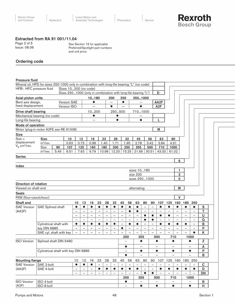
Pumps and Motors 48 Section 1
Electric Drivesand Controls Hydraulics
Linear Motion andAssembly Technologies Pneumatics Service
See Section 16 for applicable
Preferred/Spotlight part numbers
and unit price.
Extracted from RA 91 001/11.04Page 2 of 5
Issue: 06.06
Ordering code
Pressure fluid
Mineral oil, HFD for sizes 250-1000 only in combination with long-life bearing “L“ (no code)
HFB-, HFC pressure fluid Sizes 10...200 (no code)
Sizes 250...1000 (only in combination with long-life bearing “L“) E-
Axial piston unita 10...180 200 250 355...1000
Bent axis design, fixed displacement
Version SAE l — l — AA2F
Version ISO — l — l A2F
Drive shaft bearing 10...200 250...500 710...1000
Mechanical bearing (no code) l l —
Long-life bearing — l l L
Mode of operation
Motor (plug-in motor A2FE see RE 91008) M
Size
Size ≈displacement Vg cm3/rev.
Size 10 12 16 23 28 32 45 56 63 80
in3/rev. 0.63 0.73 0.98 1.40 1.71 1.95 2.78 3.42 3.84 4.91
Size 90 107 125 160 180 200 250 355 500 710 1000
in3/rev. 5.49 6.51 7.63 9.79 10.98 12.20 15.25 21.66 30.51 43.33 61.02
Series
6
Index
sizes 10...180 1
size 200 3
sizes 250...1000 0
Direction of rotation
Viewed on shaft end alternating W
Seals
FKM (flour-caoutchouc) V
Shaft end 10 12 16 23 28 32 45 56 63 80 90 107 125 160 180 250
SAE Version
(AA2F)
SAE Splined shaft l l l l l l l l l – – l l l l l S
– – – – – – – l l – – – – – – – T
– – – – – – – – – l l l l – – – U
– – – – – – – – – l l – – – – – Q
Cylindrical shaft with
key DIN 6885
l l l l l l – l l – – l l l l – B
– – – – – – l – – – – – – – – – P
SAE cyl. shaft with key – – – – – – – – – – – – – – – l K
200 355 500 710 1000
ISO Version Splined shaft DIN 5480 – l l l l Z
l – – – – A
Cylindrical shaft with key DIN 6885 – l l l l P
l – – – – B
Mounting flange 10 12 16 23 28 32 45 56 63 80 90 107 125 160 180 250
SAE Version
(AA2F)
SAE 2-bolt l l l – – – – – – – – – – – – – C
SAE 4-bolt – – – l l l l l l – – l l l l l D
– – – – – – – – – l l – – – – – DN
200 355 500 710 1000
ISO Version(A2F)
ISO 4-bolt l – – – – B
ISO 8-bolt – l l l l H

Pumps and Motors 49 Section 1
Electric Drivesand Controls Hydraulics
Linear Motion andAssembly Technologies Pneumatics Service
See Section 16 for applicable
Preferred/Spotlight part numbers
and unit price.
Service line connections
AA2F 1) 10 12 16 23 28 32 45 56 63 80 90 107 125 160 180 250
SAE ports A and B, rear 51 0 – – – l l l l l l l l l l l l l 510
SAE ports A and B 52 0 – – – l l l l l l l l l l l l l 520
at side, opposite side 7 – – – – – – l l l l l l l l l l 527
Threaded ports A and B at side, opposite side
53 0 l l l l l l – – – – – – – – – – 530
Threaded ports A and B at side and rear 2) 54 0 – – – l l l – – – – – – – – – – 540
SAE ports A and Bbottom
60 0 – – – – – – – – – – – l l – – – 600
Port plate for fitting acounterbalance valve 3) 18 1 – – – – l l l l l l l l l l l – 181
Port plate with integrated pressure relief valves 3)
19 1 – – – – l l l l l l l l l l l – 191
2 – – – – l l l l l l l l l l l – 192
A2F 3) 200 355 500 710 1000
SAE ports A and Brear
01 0 l l l l l 010
7 – l l ¢ ¢ 017
SAE ports A and B, bottom 10 0 – l – – – 100
Valves
without valves 0
with pressure relief valves (without pressure sequence range) 1
with pressure relief valves (with pressure sequence range) 2
with flushing and boost pressure valve 7
Speed measurement 10...16 23...180 200 250 355...1000
without speed measurement (no code) l l l l lprepared for speed measurement with ID sensor 4) — l – – – D
prepared for speed measurement with HDD sensor 4) — l l – 5) ¢ F
Special design
Standard design (no code)
Special design for slew drive applications (standard for port plate 19) sizes 23...180 J1) Threads of fi xing screws and service lines are SAE (UN/UNF)2) Threaded ports at side are plugged with locking screw3) Threads of fi xing screws are metric4) Complete order recommended (AA2FM inc. speed sensor)5) See RE 91001 (ISO-Version)6) No code = standard version, S = special version (sizes 5...200), SO = special version (sizes 250...1000),
K = combination with mounting part or mounting pump (sizes 5...200)
Pressure fluid
Axial piston unita
Drive shaft bearingMode of operation
Size
Series
Index
Direction of rotation
Seals
Shaft end
Mounting flange
Extracted from RA 91 001/11.04Page 3 of 5
Issue: 06.06
M / 6 W – V – 6)
l = available
¢ = in preparation
– = not available

Pumps and Motors 50 Section 1
Electric Drivesand Controls Hydraulics
Linear Motion andAssembly Technologies Pneumatics Service
See Section 16 for applicable
Preferred/Spotlight part numbers
and unit price.
Permissible radial and axial loading on the drive shaft – These are maximum values and do not apply to continous operation.
Size 5 10 12 16 23 28 32 45 56 63 80
Radial force, max. 1)
at distance a (from shaft collar) a
Fq Fq maxN(lbf)
710(160)
2100(472)
2500(562)
3250(730)
3850(865)
4800(1079)
5400(1214)
7250(1630)
8150(1832)
9150(2057)
10250(2304)2)
amm(in)
12(0.47)
16(0.63)
16(0.63)
16(0.63)
16(0.63)
16(0.63)
16(0.63)
18(0.71)
18(0.71)
18(0.71)
20(0.79)
Axial force, max. 3)–
+Fax
+Fax max N(lbf)
180(40)
320(72)
320(72)
320(72)
500(112)
500(112)
500(112)
630(142)
800(180)
800(180)
1000(225)
–Fax max N(lbf)
180(40)
320(72)
320(72)
320(72)
500(112)
500(112)
500(112)
630(142)
800(180)
800(180)
1000(225)
Permissible axial force/bar (psi) operating pressure
±Fax per./bar (psi)
N/bar(lbf/psi)
1.5(0.023)
3.0(0.05)
3.0(0.05)
3.0(0.05)
5.2(0.08)
5.2(0.08)
5.2(0.08)
7.0(0.11)
8.7(0.13)
8.7(0.13)
10.6(0.16)
Size 90 107 125 160 180 200 250 355 500 710 1000
Radial force, max. 1)
at distance a (from shaft collar) a
Fq Fq maxN(lbf)
11450(2574)2)
12100(2720)
14100(3170)
16300(3664)
18300(4114)
22900(5148)
12004)
(270)15004)
(337)19004)
(427)30004)
(674)26004)
(584)
amm(in)
20(0.79)
20(0.79)
20(0.79)
25(0.98)
25(0.98)
25(0.98)
41(1.61)
52.5(2.07)
52.5(2.07)
67.5(2.66)
67.5(2.66)
Axial force, max. 3)
–
+Fax
+Fax max N(lbf)
1000(225)
1250(281)
1250(281)
1600(360)
1600(360)
1600(360)
2000(450)
2500(562)
3000(674)
4400(989)
4400(989)
–Fax max N(lbf)
1000(225)
1250(281)
1250(281)
1600(360)
1600(360)
1600(360)
2000(450)
2500(562)
3000(674)
4400(989)
4400(989)
Permissible axial force/bar (psi) operating pressure
±Fax per./bar (psi)
N/bar(lbf/psi)
10.6(0.16)
12.9(0.20)
12.9(0.20)
16.7(0.26)
16.7(0.26)
16.7(0.26)
5) 5) 5) 5) 5)
1) during intermittent operation (sizes 5...200)2) value for Q-shaft: Fq max = 9000 N (2023 lb-ft) 3) max. permissible axial force when stopped or when axial piston unit
working in pressureless conditions.4) when stopped or when axial piston unit working in pressureless conditions.
Higher forces are permitted when under pressure, please contact us.5) please contact us
When considering the permissible axial force, the force-transfer direction must be taken into account.
– Fax max = increase in sevice life of bearings
+ Fax max = reduction in service life of bearings (avoid if at all possible)
Extracted from RA 91 001/11.04Page 4 of 5
Issue: 06.06
Technical Data
Operational pressure range – Maximum pressure on port A or B (pressure data according to DIN 24312)
AA2F Sizes 10 12 16 23 28 32 45 56 63 80 90 107 125 160 180 250 Nominal pressure Peak pressure
Shaft end: S 400 bar (5800 psi) 450 bar (6500 psi)
S 350 bar (5100 psi) 400 bar (5800 psi)
Q 300 bar (4350 psi) 350 bar (5100 psi)
Q 280 bar (4000 psi) 315 bar (4600 psi)
T 400 bar (5800 psi) 450 bar (6500 psi)
U 400 bar (5800 psi) 450 bar (6500 psi)
B 350 bar (5100 psi) 400 bar (5800 psi)
P 350 bar (5100 psi) 400 bar (5800 psi)
K 350 bar (5100 psi) 400 bar (5800 psi)
A2F Sizes 5 200 355 500 710 1000 Nominal pressure Peak pressure
Shaft end: Z 350 bar (5100 psi) 400 bar (5800 psi)
A 400 bar (5800 psi) 450 bar (6500 psi)
P 350 bar (5100 psi) 400 bar (5800 psi)
B 350 bar (5100 psi) 400 bar (5800 psi)
B 210 bar (3000 psi) 250 bar (3600 psi)
C 315 bar (4600 psi) 350 bar (5100 psi)
With pulsating loads over pN = 315 bar (4600 psi) (pmax = 350 [5100 psi]);we recommend the use of a splined shaft (AA2FM 10...250: S, T or U / A2FM 200: A / A2FM 355...1000: Z)The sum of the pressure at ports A and B may not exceed 700 bar (10000 psi) (A2F5: 630 bar (9000 psi))
Attention: shaft end with drives of radial force loads at the drive shaft (pinion, V-belt drives) necessitate reduction of the nominal pressure to pN = 315 bar (4600 psi)! Sizes 250...1000 please contact us.x

Pumps and Motors 51 Section 1
Electric Drivesand Controls Hydraulics
Linear Motion andAssembly Technologies Pneumatics Service
See Section 16 for applicable
Preferred/Spotlight part numbers
and unit price.
Extracted from RA 91 001/11.04Page 5 of 5
Issue: 06.06
Technical Data
Table of values (theoretical values, ignoring ηmh and ηvi; values rounded)
Size 5 10 12 16 23 28 32 45 56 63 80
Diplacement Vg in3 0.30 0.63 0.73 0.98 1.40 1.71 1.95 2.78 3.42 3.84 4.91
cm3 4.93 10.3 12.0 16.0 22.9 28.1 32.0 45.6 56.1 63.0 80.4
Speed max. nmax rpm 10000 8000 8000 8000 6300 6300 6300 5600 5000 5000 4500
nmax intermit.1) rpm 11000 8800 8800 8800 6900 6900 6900 6200 5500 5500 5000
Flow max. qV max gpm 13 21.8 25.3 33.9 38.2 46.6 52.2 67.4 74.0 83.1 95.6
L/min 49 82 96 128 144 176 201 255 280 315 360
Torque constants TK lb-ft/psi 0.004 0.0084 0.0097 0.013 0.019 0.023 0.026 0.037 0.045 0.051 0.065
Nm/bar 0.076 0.164 0.19 0.25 0.36 0.445 0.509 0.725 0.89 1.0 1.27
Torque at Δp = 5100 psi T lb-ft 18 2) 42 49 66 94 115 132 188 231 259 332
Δp = 350 bar T Nm 24.7 2) 57 67 88 126 156 178 254 312 350 445
Δp = 5800 psi T lb-ft – 48 56 75 107 131 150 213 263 295 377
Δp = 400 bar T Nm – 65 76 100 144 178 204 290 356 400 508
Rotary stiffness lb-ft/° 40 89 89 89 170 170 170 243 325 325 494
Nm/° 54 120 120 120 230 230 230 330 440 440 670
Mass moment of inertia
around output shaft
J lbs-ft2 0.0019 0.0095 0.0095 0.0095 0.0285 0.0285 0.0285 0.0569 0.0997 0.0997 0.1708
kgm2 0.00008 0.0004 0.0004 0.0004 0.0012 0.0012 0.0012 0.0024 0.0042 0.0042 0.0072
Filling capacity gal 0.045 0.045 0.045 0.053 0.053 0.053 0.087 0.119 0.119 0.145
L 0.17 0.17 0.17 0.20 0.20 0.20 0.33 0.45 0.45 0.55
Mass (approx.) m lbs 5.5 12 12 12 21 21 21 30 40 40 51
kg 2.5 5.4 5.4 5.4 9.5 9.5 9.5 13.5 18 18 23
Size 90 107 125 160 180 200 250 355 500 710 1000
Displacement Vg in3 5.49 6.51 7.63 9.79 10.98 12.20 15.25 21.66 30.51 43.33 61.02
cm3 90 106.7 125 160.4 180 200 250 355 500 710 1000
Speed max. nmax rpm 4500 4000 4000 3600 3600 2750 2700 2240 2000 1600 1600
nmax intermit.1) rpm 5000 4400 4400 4000 4000 3000 – – – – –
Flow max. qV max gpm 106.9 112.7 132.1 152.5 171.1 145.2 178 210 264 300 422
L/min 405 427 500 577 648 550 675 795 1000 1136 1600
Torque constants TK lb-ft/psi 0.073 0.086 0.101 0.130 0.146 0.162 0.202 0.287 0.405 0.575 0.809
Nm/bar 1,43 1,70 1,99 2,54 2,86 3,18 3,98 5,65 7,96 11,3 15,9
Torque at Δp = 5100 psi T lb-ft 371 440 516 662 742 825 1030 1465 2063 2930 4127
Δp = 350 bar T Nm 501 595 697 889 1001 1114 1393 1978 2785 3955 5570
Δp = 5800 psi T lb-ft 422 500 587 753 844 938 – – – – –
Δp = 400 bar T Nm 572 680 796 1016 1144 1272 – – – – –
Rotary stiffness lb-ft/° 494 649 649 996 996 2146 2753 3756 6069 13832 13832
Nm/° 670 880 880 1350 1350 2910 3733 5092 8228 18753 18753
Mass moment of inertia
around output shaft
J lbs-ft2 0.1708 0.2753 0.2753 0.5221 0.5221 0.8970 1.4475 2.4205 4.2240 13.052 13.052
kgm2 0.0072 0.0116 0.0116 0.0220 0.0220 0.0378 0.061 0.102 0.178 0.55 0.55
Filling capacity gal 0.145 0.211 0.211 0.291 0.291 0.713 0.660 0.925 1.110 2.113 2.113
L 0.55 0.8 0.8 1.1 1.1 2.7 2.5 3.5 4.2 8 8
Mass (approx.) m lbs 51 71 71 99 99 145 161 242 342 715 741
kg 23 32 32 45 45 66 73 110 155 325 3361) intermittent maximum speed: overspeed at discharge and over-running travel operations, t < 5 sec. and Δp < 150 bar (2200 psi)2) Δp = 315 bar (4600 psi)

Pumps and Motors 52 Section 1
Electric Drivesand Controls Hydraulics
Linear Motion andAssembly Technologies Pneumatics Service
See Section 16 for applicable
Preferred/Spotlight part numbers
and unit price.
Extracted from RA 91 172/10.03Page 1 of 4
Issue: 06.06
Fixed displacement motor
for open and closed circuits,
Axial piston, swashplate design
Model A10FM, Standard version
Model A10FE, Plug-in version
Size 10...63
Series 5
Nominal pressure 4060 psi (280 bar)
Peak pressure 5100 psi (350 bar)
– Output speed proportional to inlet fl ow
– Output torque increases with the pressure gradient between
high and low-pressure sides
– For mobile and industrial use
– Long service life
– High permissible output speeds
– Well proven A10-rotary group
– High power to weight ratio- compact size
– Low noise levels
– Mechanical and hydraulic connections acc. to SAE standards
– Optional speed pickup
– Integrated anti cavitation valve optional, i.e. fan drives
– Plug-in version for space saving installation
Model A10FM, size 23 to 63
A10FE, size 10 to 45 A10FE, size 11 to 18
(2-hole fl ange) (8-hole fl ange)

Pumps and Motors 53 Section 1
Electric Drivesand Controls Hydraulics
Linear Motion andAssembly Technologies Pneumatics Service
See Section 16 for applicable
Preferred/Spotlight part numbers
and unit price.
Hydraulic fluid
Mineral oil (without prefix)
Axial piston motor
Swashplate design fixed displacement, nomi-nal pressure 4060psi (280 bar) peak pres-sure 5000 psi (350 bar)
A10F
Operating mode
Motor M
Size
Displacement Vg in cm3 18 23 28 37 45 58 63
in3/rev 1.10 1.43 1.73 2.23 2.71 3.53 3.84
cm3/rev 18 23.5 28.5 36.7 44.5 58 63.1
❍ ● ● ● ● ● ●
Series
5
Index
2
Direction of rotation (Looking at shaft end)
changing W
with valve option “2“ only right 1) R
with valve option “2“ only left 1) L
Seals
FPM fluororubber V
Shaft end 18 23 28 37 45 58 63
❍ ● ● ● ● ● ●
— ❍ ❍ ● ● ● ●
❍ ● ● ● ● ❍ ❍
SAE splined shaft with runout R
SAE splined shaft with runout W
Tapered with woodruff key C
Mounting flange
SAE 2-hole ❍ ● ● ● ● ● ● C
Ports for service lines 18 23 28 37 45 58 63
— ● ● ● ● ● ●
❍ ● ● ● ● ● ●
❍ ❍ ❍ ● ● ❍ ❍
❍ ● ● ● ● ❍ ❍
Ports A/B on side - same side; SAE flange, UNC threaded bolt holes 60N00
Threaded ports A/B on side - same side; UNF thread 66N00
Ports A/B at rear - SAE flange, UNC threaded bolt holes 61N00
SAE threaded ports at rear - UNF thread 64N00
Valves 18 23 28 37 45 58 63
❍ ● ● ● ● ● ●
— ● ● ● ● ● ●
❍ ● ● ● ● ● ●
Without valves 0
Integrated flushing valve 7 2)
Integrated anti-cavitation valve 2 1,2)
Speed pickup
Without speed pickup (no code) ❍ ● ● ● ● ● ●
❍ ● ● ● ● ● ●Prepared for speed pickup (for inductive sensor ID) D
1) Integrated anti-cav valve requires selection of R- or L hand rotation2) with port for service lines option “60N00“ and “66N00“
A10F M / 5 2 – V C
Extracted from RA 91 172/10.03Page 2 of 4
Issue: 06.06
● = available ❍ = in preparation – = not available
Ordering code
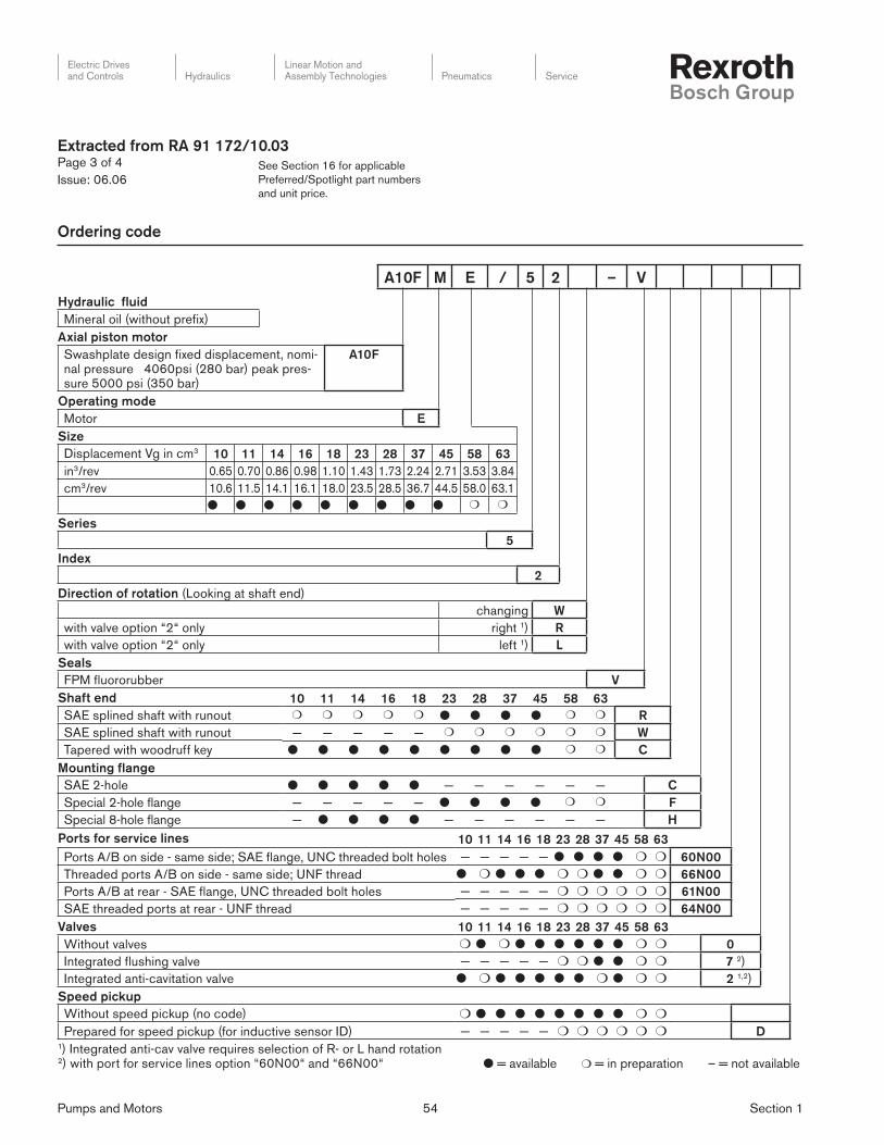
Pumps and Motors 54 Section 1
Electric Drivesand Controls Hydraulics
Linear Motion andAssembly Technologies Pneumatics Service
See Section 16 for applicable
Preferred/Spotlight part numbers
and unit price.
Ordering code
Hydraulic fluid
Mineral oil (without prefix)
Axial piston motor
Swashplate design fixed displacement, nomi-nal pressure 4060psi (280 bar) peak pres-sure 5000 psi (350 bar)
A10F
Operating mode
Motor E
Size
Displacement Vg in cm3 10 11 14 16 18 23 28 37 45 58 63
0.65 0.70 0.86 0.98 1.10 1.43 1.73 2.24 2.71 3.53 3.84
10.6 11.5 14.1 16.1 18.0 23.5 28.5 36.7 44.5 58.0 63.1
● ● ● ● ● ● ● ● ● ❍ ❍
in3/rev
cm3/rev
Series
5
Index
2
Direction of rotation (Looking at shaft end)
changing W
with valve option “2“ only right 1) R
with valve option “2“ only left 1) L
Seals
FPM fluororubber V
Shaft end 10 11 14 16 18 23 28 37 45 58 63
❍ ❍ ❍ ❍ ❍ ● ● ● ● ❍ ❍
— — — — — ❍ ❍ ❍ ❍ ❍ ❍
● ● ● ● ● ● ● ● ● ❍ ❍
SAE splined shaft with runout R
SAE splined shaft with runout W
Tapered with woodruff key C
Mounting flange
SAE 2-hole ● ● ● ● ● — — — — — —
— — — — — ● ● ● ● ❍ ❍
— ● ● ● ● — — — — — —
C
Special 2-hole flange F
Special 8-hole flange H
Ports for service lines 10 11 14 16 18 23 28 37 45 58 63
— — — — — ● ● ● ● ❍ ❍
● ❍ ● ● ● ❍ ❍ ● ● ❍ ❍
— — — — — ❍ ❍ ❍ ❍ ❍ ❍
— — — — — ❍ ❍ ❍ ❍ ❍ ❍
Ports A/B on side - same side; SAE flange, UNC threaded bolt holes 60N00
Threaded ports A/B on side - same side; UNF thread 66N00
Ports A/B at rear - SAE flange, UNC threaded bolt holes 61N00
SAE threaded ports at rear - UNF thread 64N00
Valves 10 11 14 16 18 23 28 37 45 58 63
❍ ● ❍ ● ● ● ● ● ● ❍ ❍
— — — — — ❍ ❍ ● ● ❍ ❍
● ❍ ● ● ● ● ● ❍ ● ❍ ❍
Without valves 0
Integrated flushing valve 7 2)
Integrated anti-cavitation valve 2 1,2)
Speed pickup
Without speed pickup (no code) ❍ ● ● ● ● ● ● ● ● ❍ ❍
— — — — — ❍ ❍ ❍ ❍ ❍ ❍Prepared for speed pickup (for inductive sensor ID) D1) Integrated anti-cav valve requires selection of R- or L hand rotation2) with port for service lines option “60N00“ and “66N00“
A10F M E / 5 2 – V
Extracted from RA 91 172/10.03Page 3 of 4
Issue: 06.06
● = available ❍ = in preparation – = not available

Pumps and Motors 55 Section 1
Electric Drivesand Controls Hydraulics
Linear Motion andAssembly Technologies Pneumatics Service
See Section 16 for applicable
Preferred/Spotlight part numbers
and unit price.
Extracted from RA 91 172/10.03Page 4 of 4
Issue: 06.06
Technical data
± Fax
Fq
X
X/2 X/2
Applied force with shaft R and W Applied force with shaft C
± Fax
Fq
X
X/2 X/2
1) Maximum speed depending on outlet pressure
0
1.00
0.95
0.90
0.85
0.8029(2)
58(4)
87(6)
116(8)
145(10)
174(12)
203(14)
232(16)
261(18)
Moto
r sp
eed
n/n
max
Outlet pressure PND in PSI (bar)
Table of values (theoretical values, without considering ηmh and ηv: values rounded)
Size 10 11 14 16 18
Motor displacement Vg max in3 (cm3) 0.65 (10.6) 0.70 (11.5) 0.86 (14.1) 0.98 (16.1) 1.10 (18)
Max. speed 1) nmax rpm 5000 4200 4200 4200 4200
Max. inlet flow at nmax qv max gpm (L/min) 14 (53) 12.7 (48) 15.6 (59) 17.9 (68) 20.1 (76)
Max. power at nmax Δp = 4060 psi (280 bar) Pmax HP (kW) 33 (24.7) 30 (22.5) 37 (27.6) 42 (31.6) 47 (35.3)
Max. torque at Vg max Δp = 4060 psi (280 bar) Tmax lb-ft (Nm) 34.6 (47) 37.6 (51) 46.5 (63) 53.1 (72) 59 (80)
Mass moment of inertia (about the output shaft) J lb-ft2 0.014 0.022 0.022 0.022 0.022
(kgm2) (0.0006) (0.00093) (0.00093) (0.00093) (0.00093)
Filling volume. approx. gal. (L) 0.026(0.1) 0.039(0.15) 0.039(0.15) 0.039(0.15) 0.039(0.15)
Weight. approx. m lbs (kg) 11 (5) 14.3 (6.5) 14.3 (6.5) 14.3 (6.5) 14.3 (6.5)
Permissible load on output shaft. max. perm. axial force Fax max lbf (N) 900 (400) 1570 (700) 1570 (700) 1570 (700) 1570 (700)
Max. perm. radial force Fq max lbf (N) 560 (250) 790 (350) 790 (350) 790 (350) 790 (350)
Actual starting torque at n = 0 min–1
Δp = 4060 psi (280 bar)
T lb-ft (Nm) 27.6 (37.5) 22.1 (30) 33.2 (45) 39.1 (53) 49.8 (67.5)
Table of values (theoretical values, without considering ηmh and ηv: values rounded)
Size 23 28 37 45 58 63
Motor displacement Vg max in3 (cm3) 1.43(23.5) 1.73(28.5) 2.24(36.7) 2.71(44.5) 3.53(58) 3.84(63.1)
Max. speed 1) nmax rpm 4900 4700 4200 4000 3600 3400
Max. inlet flow at nmax qv max gpm (L/min) 30.4(115) 35.4(134) 40.7(154) 47(178) 55.2(209) 56.8(215)
Max. power at nmax Δp = 4060 psi (280 bar) Pmax HP (kW) 71(53.6) 83(62.5) 95(71.8) 111(83.1) 130(97.4) 133(100.1)
Max. torque at Vg max Δp = 4060 psi (280 bar) Tmax lb-ft (Nm) 77.4(105) 93.7(127) 120(163) 146(198) 190(258) 207(281)
Mass moment of inertia (about the output shaft) J lb-ft2 0.04 0.04 0.078 0.078 0.133 0.133
(kgm2) (0.0017) (0.0017) (0.0033) (0.0033) (0.0056) (0.0056)
Filling volume. approx. gal. (L) 0.16(0.6) 0.16(0.6) 0.185(0.7) 0.185(0.7) 0.21(0.8) 0.21(0.8)
Weight. approx. m lbs (kg) 26.5(12) 26.5(12) 37.5(17) 37.5(17) 48.5(22) 48.5(22)
Permissible load on output shaft. max. perm.
axial force
Fax max lbf (N) 2250(1000) 2250(1000) 3370(1500) 3370(1500) 4500(2000) 4500(2000)
Max. perm. radial force Fq max lbf (N) 2700(1200) 2700(1200) 3370(1500) 3370(1500) 3820(1700) 3820(1700)
Actual starting torque at n = 0 min–1
Δp = 4060 psi (280 bar)
T lb-ft (Nm) 55.3(75) 77.4(105) 92.2(125) 125(170) 151(205) 169(230)

Pumps and Motors 56 Section 1
Electric Drivesand Controls Hydraulics
Linear Motion andAssembly Technologies Pneumatics Service
See Section 16 for applicable
Preferred/Spotlight part numbers
and unit price.
Extracted from RA 91 401/07.05Page 1 of 4
Issue: 06.06
Fixed displacement pump
for open circuits,
Axial piston, bent axis design
Model AA2FO (A2FO)
Sizes Nominal pressure/Peak pressure
5 4600/5100 psi (315/350 bar)
10...200 5800/6500 psi (400/450 bar)
250...1000 5100/5800 psi (350/400 bar)
Series 6
– Fixed displacement pump AA2FO of axial piston, bent axis
design, suitable for hydrostatic drives in open circuits
– Use in mobile and industrial applications
– Output fl ow is proportional to drive speed and displacement
– The drive shaft bearings are designed to give the service life
expected in these areas of operation
– High power density
– Compact design
– High overall effi ciency
– Cost effective concept
– One piece pistons with piston rings
Additional instructions in text form
Seals
The fi xed pump A2F5 is equipped with
Buna-N (NBR) seals in standard design.
In case of need FKM- (fl uor-caoutchouc)
seals please indicate when ordering in
clear text:
"with FKM-seals"
Axial piston unit
01 Bent axis design, fi xed displacement A2F
Size
02
Size 5
≈ Displacement Vg in3/rev. 0.30
cm3/rev. 4.93
Series
03 60
Direction of rotation
04Viewed on shaft end clockwise R
counter-clockwise L
Shaft end
05Parallel keyed shaft DIN 6885 B
Tapered shaft with threaded end and woodruff key per DIN 6888 C
Service line ports
06 Threaded ports A und B at side, metric 7
A2F 5 / 60 – 7
01 02 03 04 05 06
Ordering code for size 5

Pumps and Motors 57 Section 1
Electric Drivesand Controls Hydraulics
Linear Motion andAssembly Technologies Pneumatics Service
See Section 16 for applicable
Preferred/Spotlight part numbers
and unit price.
Extracted from RA 91 401/07.05Page 2 of 4
Issue: 06.06
Ordering code
O / 6 – V
01 02 03 04 05 06 07 08 09 10 11 12
Hydraulic fl uid
01
Mineral oil, HFD for sizes 250...1000 only in combination with long-life bearing “L“ (no code)
HFB-, HFC hydraulic fl uid Sizes 10...200 (no code)
Sizes 250...1000 (only in combination with long-life bearing “L“) E-
Axial piston unit 10...180 200 250 355...1000
02Bent axis design,
fi xed displacement
Version SAE – – AA2F
Version ISO – – A2F
Drive shaft bearing 10...200 250...500 710...1000
03Mechanical bearing (no code) –
Long-life bearing – L
Mode of operation
04 Pump, open circuits O
Size
05
Size ≈ displacement Vg (cm3)
Size 10 12 16 23 28 32 45 56 63 80
in3/rev. 0.63 0.73 0.98 1.40 1.71 1.95 2.78 3.42 3.84 4.91
Size 90 107 125 160 180 200 250 355 500 710 1000
in3/rev. 5.49 6.51 7.63 9.79 10.98 12.20 15.25 21.66 30.51 43.33 61.02
Series
06 6
Index
07
sizes 10...180 1
size 200 3
sizes 250...1000 0
Direction of rotation
08Viewed on shaft end clockwise R
counter-clockwise L
Seals
09 FKM (fl our-caoutchouc) V

Pumps and Motors 58 Section 1
Electric Drivesand Controls Hydraulics
Linear Motion andAssembly Technologies Pneumatics Service
See Section 16 for applicable
Preferred/Spotlight part numbers
and unit price.
Extracted from RA 91 401/07.05Page 3 of 4
Issue: 06.06
O / 6 – V
01 02 03 04 05 06 07 08 09 10 11 12
Shaft end 10 12 16 23 28 32 45 56 63 80 90 107 125 160 180 250
10
SAE Version
(AA2F)
SAE
Splined shaft– – S
– – – – – – – – – – – – – – T
– – – – – – – – – – – – U
– – – – – – – – – – – – – – Q
Parallel keyed shaft
DIN 6885– – – – B
– – – – – – – – – – – – – – – P
SAE parallel keyed shaft – – – – – – – – – – – – – – – K
200 355 500 710 1000
ISO Version
(A2F)
Splined shaft
DIN 5480– – – – A
– Z
Parallel keyed shaft
DIN 6885– – – – B
– P
Mounting fl ange 10 12 16 23 28 32 45 56 63 80 90 107 125 160 180 250
11
SAE Version
(AA2F)
2-bolt – SAE – – – – – – – – – – – – – C
4-bolt – SAE – – – – – D
– – – – – – – – – – – – – – DN
200 355 500 710 1000
ISO Version
(A2F)
4-bolt – ISO – – – – B
8-bolt – ISO – H
Service line ports
12
AA2F 1) 10 12 16 23 28 32 45 56 63 80 90 107 125 160 180 250
SAE flange ports A and B, at side and
SAE flange port S, rear– – – 55
Threaded ports A and B, at side and
SAE fl ange port S, rear– – – – – – – – – – – – – 56
A2F 2) 200 355 500 710 1000
SAE flange ports A and B, at side and
SAE flange port S, rear– – – – 05
SAE flange ports A and B, rear and
SAE flange port S, rear– 11
1) threads of fastening screws and service lines are SAE (UN/UNF)2) threads of fastening screws are metric
= available – = not available
Ordering code

Pumps and Motors 59 Section 1
Electric Drivesand Controls Hydraulics
Linear Motion andAssembly Technologies Pneumatics Service
See Section 16 for applicable
Preferred/Spotlight part numbers
and unit price.
Size 5 10 12 16 23 28 32 45 56 63 80
DiplacementVg in3 0.30 0.63 0.73 0.98 1.40 1.71 1.95 2.78 3.42 3.84 4.91
cm3 4.93 10.3 12 16 22.9 28.1 32 45.6 56.1 63 80.4
Speed max. nmax1) rpm 5600 3150 3150 3150 2500 2500 2500 2240 2000 2000 1800
nmax limit 2) rpm 8000 6000 6000 6000 4750 4750 4750 4250 3750 3750 3350
Flow max. qV max gpm 7.3 8.6 10.0 13.2 15.1 18.5 21.1 27.0 29.6 33.3 38.0
L/min 27.6 32.4 37.8 50 57 70 80 102 112 126 144
Power at Δp = 5100 psi Pmax HP 19.53) 25 30 39 44 55 63 80 88 99 113
Δp = 350 bar Pmax kW 14.53) 18.9 22 29.2 33 41 47 59.5 65 73.5 84
Δp = 5800 psi Pmax HP – 30 34 45 51 63 71 91 100 113 129
Δp = 400 bar Pmax kW – 22 25 34 38 47 53 68 75 84 96
Torque at Δp = 5100 psi T lb-ft 18 3) 42 50 65 94 116 132 189 232 260 331
Δp = 350 bar T Nm 24.7 3) 57 67 88 126 156 178 254 312 350 445
Δp = 5800 psi T lb-ft – 48 56 75 107 131 150 214 263 295 377
Δp = 400 bar T Nm – 65 76 101 145 178 203 290 356 400 511
Mass moment of inertia
around output shaft
J lbs-ft2 0.0019 0.0095 0.0095 0.0095 0.0285 0.0285 0.0285 0.0569 0.0997 0.0997 0.1708
kgm2 0.00008 0.0004 0.0004 0.0004 0.0012 0.0012 0.0012 0.0024 0.0042 0.0042 0.0072
Case fi ll capacity gal 0.045 0.045 0.045 0.053 0.053 0.053 0.087 0.119 0.119 0.145
L 0.17 0.17 0.17 0.20 0.20 0.20 0.33 0.45 0.45 0.55
Weight (approx.) m lbs 5.5 12 12 12 21 21 21 30 40 40 51
kg 2.5 5.4 5.4 5.4 9.5 9.5 9.5 13.5 18 18 23
Size 90 107 125 160 180 200 250 355 500 710 1000
DisplacementVg in3 5.49 6.51 7.63 9.79 10.98 12.20 15.25 21.66 30.51 43.33 61.02
cm3 90 106.7 125 160.4 180 200 250 355 500 710 1000
Speed max. nmax1) rpm 1800 1600 1600 1450 1450 1550 1500 1320 1200 1200 950
nmax limit 2) rpm 3350 3000 3000 2650 2650 2750 1800 1600 1500 1500 1200
Flow max. qV max gpm 42.8 44.9 52.8 61.2 69.0 81.9 99.1 123.9 158.5 218.2 251.0
L/min 162 170 200 232 261 310 375 469 600 826 950
Power at Δp = 5100 psi Pmax HP 127 134 157 183 205 244 295 368 472 670 747
Δp = 350 bar Pmax kW 95 100 117 135 152 181 219 273 350 497 554
Δp = 5800 psi Pmax HP 145 153 179 208 233 277 – – – – –
Δp = 400 bar Pmax kW 108 114 133 155 174 207 – – – – –
Torque at Δp = 5100 psi T lb-ft 372 442 517 664 746 828 1036 1470 2070 2940 4141
Δp = 350 bar T Nm 501 594 696 893 1003 1114 1393 1978 2785 3955 5570
Δp = 5800 psi T lb-ft 422 500 586 752 845 938 – – – – –
Δp = 400 bar T Nm 572 678 795 1020 1145 1272 – – – – –
Mass moment of inertia
around output shaft
J lbs-ft2 0.1708 0.2753 0.2753 0.5221 0.5221 0.8970 1.4475 2.4205 4.2240 13.052 13.052
kgm2 0.0072 0.0116 0.0116 0.0220 0.0220 0.0378 0.061 0.102 0.178 0.55 0.55
Case fi ll capacity gal 0.145 0.211 0.211 0.291 0.291 0.713 0.660 0.925 1.110 2.113 2.113
L 0.55 0.8 0.8 1.1 1.1 2.7 2.5 3.5 4.2 8 8
Weight (approx.) m lbs 51 71 71 99 99 145 161 242 342 715 741
kg 23 32 32 45 45 66 73 110 155 325 3361) The values shown are valid for an absolute pressure (pabs) of 14.5 psi (1 bar) at the suction inlet S and when operated on
mineral oil (with a specifi c mass of 7.36 lbs/gal (0.88 kg/L)).2) By increase of the input pressure (pabs > 14.5 psi / 1 bar) the rotational speeds can be increased to the max. admissible
speeds nmax limit (speed limits).3) Δp = 4600 psi (315 bar)
Technical data (theoretical values, without considering ηmh and ηv; values rounded)
Extracted from RA 91 401/07.05Page 4 of 4
Issue: 06.06

Pumps and Motors 60 Section 1
Electric Drivesand Controls Hydraulics
Linear Motion andAssembly Technologies Pneumatics Service
See Section 16 for applicable
Preferred/Spotlight part numbers
and unit price.
Extracted from RA 91 604/02.04Page 1 of 4
Issue: 06.06
Variable displacement motor
for open and closed circuits,
Axial piston, bent axis design
Model AA6VM (A6VM)
Sizes 28...1000
Series 6
Nominal pressure 5800 psi (400 bar)
Peak pressure 6500 psi (450 bar)
Sizes 250...1000
Nominal pressure 5100 psi (350 bar)
Peak pressure 5800 psi (400 bar)
– Variable displacement axial piston motor of bent axis design for
hydrostatic transmissions in open and closed circuits
– For use in mobile and stationary applications
– The wide control range enables the variable displacement mo-
tor to satisfy the requirement for high rotational speed and high
torque.
– The displacement is continuously variable from Vg max to
Vg min = 0.
– The output speed depends on the fl ow capacity of the pumps
and the displacement of the motor.
– The torque increases with the pressure differential between the
high and low pressure side and with increasing displacement.
– Wide control range with hydrostatic transmissions
– Wide selection of regulating and control devices
– Cost savings as no need for shiftable gearboxes and possibility
to use smaller pumps
– Rugged, compact bearing system with long service life
– High power density
– Favorable start-up effi ciency
– Low moment of inertia
– Large swivel range

Pumps and Motors 61 Section 1
Electric Drivesand Controls Hydraulics
Linear Motion andAssembly Technologies Pneumatics Service
See Section 16 for applicable
Preferred/Spotlight part numbers
and unit price.
Technical Data
Minimum inlet pressure on service line port A(B)
To prevent damage to the variable displacement motor, there has to be a minimum inlet pressure in the inlet area.
The minimum inlet pressure depends on the speed and swivel angle (displacement) of the variable displacement motor.
Please contact us if these conditions cannot be satisfied.
Permitted displacement in relation to rotational speed
n / nmax
Dis
pla
cem
ent
Vg /
Vg
max
Inle
t p
ressure
pab
s. m
in p
si (b
ar)
n / nmax 0
Table of values (theoretical values, ignoring ηmh and ηv; values rounded)
Size 28 55 80 107 140 160 200 250 355 500 1000
Displacement 1) Vg max in3 1.71 3.34 4.88 6.53 8.54 9.76 12.20 15.25 21.66 30.51 61.02
cm3 28.1 54.8 80 107 140 160 200 250 355 500 1000
Vg 0 in3 0 0 0 0 0 0 0 0 0 0 0
cm3 0 0 0 0 0 0 0 0 0 0 0
Rotational speed max.
(while adhering to
max. permitted fl ow)
nmax at Vg max rpm 5550 4450 3900 3550 3250 3100 2900 2700 2240 2000 1600
nmax1 at Vg < Vg,1 rpm 8750 7000 6150 5600 5150 4900 4600 3600 2950 2650 2100
Vg,1 in3 1.10 2.14 3.11 4.15 5.37 6.16 7.69 11.47 16.48 23.00 46.5
cm3 18 35 51 68 88 101 126 188 270 377 762
nmax 0 at Vg 0 rpm 10450 8350 7350 6300 5750 5500 5100 3600 2950 2650 2100
Flow max. qV max gpm 41 64 82 100 120 131 153 178 210 264 423
L/min 156 244 312 380 455 496 580 675 795 1000 1600
Torque max. Tmax at Vg max 2) lb-ft 132 257 ??? 502 657 752 939 1026 1459 2054 4109
Nm 179 349 509 681 891 1019 1273 1391 1978 2785 5571
Torsional rigidity lb-ft/rad 266 516 848 1151 1545 1711 2146 2753 3756 6069 13832
Nm/rad 360 700 1150 1560 2095 2320 2910 3733 5092 8228 18753
Mass moment of inertia
around output shaft
J lbs-ft2 0.033 0.100 0.190 0.301 0.491 0.600 0.838 1.448 2.420 4.224 13.05
kgm2 0.0014 0.0042 0.0080 0.0127 0.0207 0.0253 0.0353 0.061 0.102 0.178 0.550
Filling capacity L 0.5 0.75 1.2 1.5 1.8 2.4 2.7 3.0 5.0 7.0 16.0
Mass (approx.) m lbs 35 57 75 104 132 141 176 198 375 463 948
kg 16 26 34 47 60 64 80 90 170 210 430
1) The minimum and maximum displacement are continuously variable, see model codes on page 2.
(default setting sizes 250 to 1000 unless specified in order: Vg min = 0.2 • Vg max , Vg max = Vg max).2) sizes 28 to 200: Δp = 5800 psi (400 bar); sizes 250 to 1000: Δp = 5100 psi (350 bar)
0 0.2 0.4 0.6 0.8 1
30 (2) 15 (1)
60 (4)
90 (6)
115 (8)
145 (10)
175 (12)
200 (14)
230 (16)
Vg max
Vg 1
0.3 Vg max
0.2 0
0.2
0.4
0.4
0.6
0.6
0.8
0.8
1.0
1.0
1.2 1.4 1.6
sizes 28...200
sizes 250...1000
Extracted from RA 91 604/02.04Page 4 of 4
Issue: 06.06

Pumps and Motors 62 Section 1
Electric Drivesand Controls Hydraulics
Linear Motion andAssembly Technologies Pneumatics Service
See Section 16 for applicable
Preferred/Spotlight part numbers
and unit price.
Pressure fluid
Petroleum oil (no character), HFD for sizes 250-1000 only in combination with long-life bearing “L”
HFB, HFC pressure fluid Sizes 28 to 200 (no character)
Sizes 250 to 1000 (only in combination with long-life bearing “L”) E
Axial piston unit 28 55 80 107 140 160 200 250 355 500 1000
Bent-axis type, variable Version SAE – ● ● ● – ● ● ● – – – AA6V
Version ISO ● 1) 1) 1) ● 1) 1) 1) ● ● ● A6V
Drive shaft bearing 28...200 250 355 500 1000
Standard bearing (no character) ● ● ● ● –
Long-life bearing – ● ● ● ● L
Operation mode
Motor (A6VE plug-in motor, see RE 91606) M
Size
Displacement Vg max in3/rev 1.71 3.34 4.88 6.53 8.54 9.76 12.20 15.25 21.66 30.51 61.02
cm3/rev 28 55 80 107 140 160 200 250 355 500 1000
Control device 28 55 80 107 140 160 200 250 355 500 1000
Hydraulic control, Δp = 145 psi (10 bar) HD1 ● ● ● ● ● ● ● ● ● ● ● HD1
pilot pressure dependent Δp = 365 psi (25 bar) HD2 ● ● ● ● ● ● ● ● ● ● ● HD2
Δp = 508 psi (35 bar) HD3 – – – – – – – ● ● ● ● HD3
Hydraulic two-point control HZ – – – – – – – ● ● ● ● HZ
HZ1 ● – – – ● ● ● – – – – HZ1
HZ3 – ● ● ● – – – – – – – HZ3
Electrical control, with 12 V EP1 ● ● ● ● ● ● ● ● ● ● ● EP1
proportional solenoid (sizes 28 to 200) 2) 24 V EP2 ● ● ● ● ● ● ● ● ● ● ● EP2
Electrical two-point control, 12 V EZ1 ● – – – ● ● ● ● ● ● ● EZ1
with solenoid 24 V EZ2 ● – – – ● ● ● ● ● ● ● EZ2
12 V EZ3 – ● ● ● – – – – – – – EZ3
24 V EZ4 – ● ● ● – – – – – – – EZ4
Automatic control, without pressure rise HA1 ● ● ● ● ● ● ● ● ● ● ● HA1
high-pressure dependent with pressure rise Δp = 1450 psi (100 bar) HA2 ● ● ● ● ● ● ● ● ● ● ● HA2
Hydraulic control, speed dependent
pSt/pHD = 3/100, hydraulic travel direction valve DA – – – – – – – ● ● ● ❍ DA
pSt/pHD = 5/100, hydraulic travel direction valve DA1 ● ● ● ● ● ● ● – – – – DA1
electrical travel direction valve 12 V DA2 ● ● ● ● ● ● ● – – – – DA2
+ electrical Vg max switch 24 V DA3 ● ● ● ● ● ● ● – – – – DA3
pSt/pHD = 8/100, hydraulic travel direction valve DA4 ● ● ● ● ● ● ● – – – – DA4
electrical travel direction valve 12 V DA5 ● ● ● ● ● ● ● – – – – DA5
+ electrical Vg max switch 24 V DA6 ● ● ● ● ● ● ● – – – – DA6
Pressure control (for HD, EP only) 28 55 80 107 140 160 200 250 355 500 1000
without pressure control (no character) ● ● ● ● ● ● ● ● ● ● ●
Pressure control direct ● ● ● ● ● ● ● ● ● ● ● D
direct, with 2nd pressure setting ● ● ● ● ● ● ● 3) 3) 3) 3) E
remotely controlled – – – – – – – ● ● ● ● G
Overriding HA control (for HA1, HA2 only)
without override (no character) ● ● ● ● ● ● ● ● ● ● ●
Hydraulic override ● ● ● ● ● ● ● ● ● ● ● T
Electrical override 12 V ● ● ● ● ● ● ● – – – – U1
24 V ● ● ● ● ● ● ● – – – – U2
Electrical override 12 V ● ● ● ● ● ● ● – – – – R1
+ electrical travel direction valve 24 V ● ● ● ● ● ● ● – – – – R2
Series
Series 6, Index 3 63
Direction of rotation
when viewing shaft end, alternating W
Setting range for displacement 4) 28 55 80 107 140 160 200 250 355 500 1000
Vg min = 0 to 0.8 Vg max (no character) ● ● ● ● ● ● ● – – – –
Vg min = 0 to 0.4 Vg max Vg max = Vg max to 0.8 Vg max – – – – – – – ● ● ● ● 1
Vg min > 0.4 Vg max to 0.8 Vg max Vg max = Vg max to 0.8 Vg max – – – – – – – ● ● ● ● 2
1) ISO-Version see RE 91604 2) with proportional valve (sizes 250 to 1000) 3) supplied as standard with D version (sizes 250 to 1000)4) please specify precise values for Vg min and Vg max in plain text when placing your order: V g min = ... cm3, V g max = ... cm3
Ordering Code
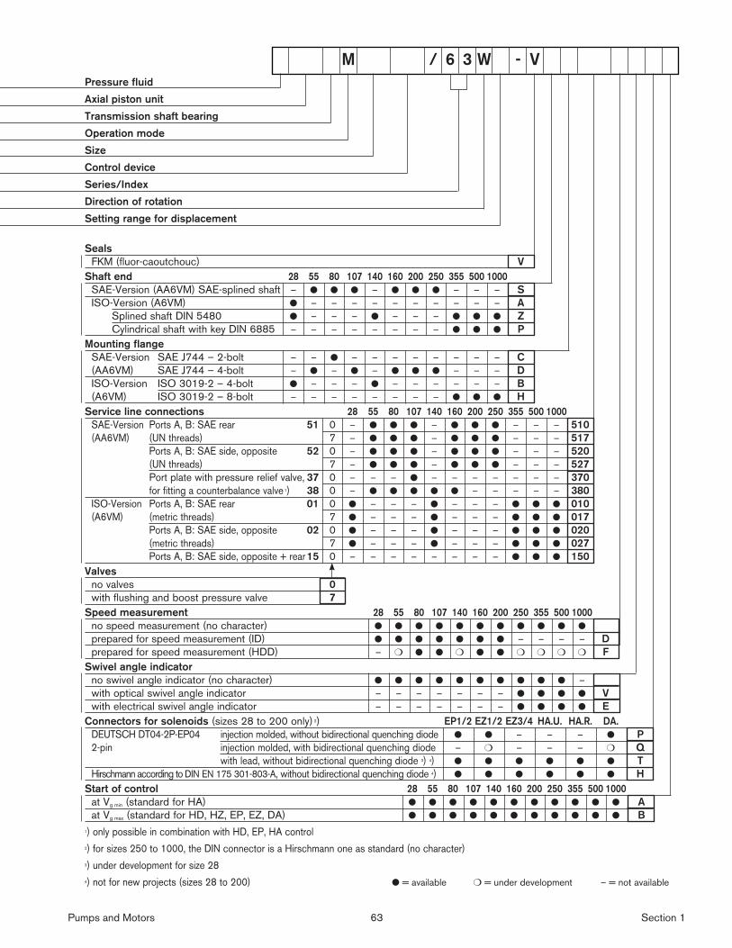
Pumps and Motors 63 Section 1
Electric Drivesand Controls Hydraulics
Linear Motion andAssembly Technologies Pneumatics Service
See Section 16 for applicable
Preferred/Spotlight part numbers
and unit price.
Pressure fluid
Axial piston unit
Transmission shaft bearing
Operation mode
Size
Control device
Series/Index
Direction of rotation
Setting range for displacement
Seals
FKM (fluor-caoutchouc) V
Shaft end 28 55 80 107 140 160 200 250 355 500 1000
SAE-Version (AA6VM) SAE-splined shaft – ● ● ● – ● ● ● – – – S
ISO-Version (A6VM) ● – – – – – – – – – – A
Splined shaft DIN 5480 ● – – – ● – – – ● ● ● Z
Cylindrical shaft with key DIN 6885 – – – – – – – – ● ● ● P
Mounting flange
SAE-Version SAE J744 – 2-bolt – – ● – – – – – – – – C
(AA6VM) SAE J744 – 4-bolt – ● – ● – ● ● ● – – – D
ISO-Version ISO 3019-2 – 4-bolt ● – – – ● – – – – – – B
(A6VM) ISO 3019-2 – 8-bolt – – – – – – – – ● ● ● H
Service line connections 28 55 80 107 140 160 200 250 355 500 1000
SAE-Version Ports A, B: SAE rear 51 0 – ● ● ● – ● ● ● – – – 510
(AA6VM) (UN threads) 7 – ● ● ● – ● ● ● – – – 517
Ports A, B: SAE side, opposite 52 0 – ● ● ● – ● ● ● – – – 520
(UN threads) 7 – ● ● ● – ● ● ● – – – 527
Port plate with pressure relief valve, 37 0 – – – ● – – – – – – – 370
for fitting a counterbalance valve 1) 38 0 – ● ● ● ● ● – – – – – 380
ISO-Version Ports A, B: SAE rear 01 0 ● – – – ● – – – ● ● ● 010
(A6VM) (metric threads) 7 ● – – – ● – – – ● ● ● 017
Ports A, B: SAE side, opposite 02 0 ● – – – ● – – – ● ● ● 020
(metric threads) 7 ● – – – ● – – – ● ● ● 027
Ports A, B: SAE side, opposite + rear 15 0 – – – – – – – – ● ● ● 150
Valves
no valves 0
with flushing and boost pressure valve 7
Speed measurement 28 55 80 107 140 160 200 250 355 500 1000
no speed measurement (no character) ● ● ● ● ● ● ● ● ● ● ●
prepared for speed measurement (ID) ● ● ● ● ● ● ● – – – – D
prepared for speed measurement (HDD) – ❍ ● ● ❍ ● ● ❍ ❍ ❍ ❍ F
Swivel angle indicator
no swivel angle indicator (no character) ● ● ● ● ● ● ● ● ● ● –
with optical swivel angle indicator – – – – – – – ● ● ● ● V
with electrical swivel angle indicator – – – – – – – ● ● ● ● E
Connectors for solenoids (sizes 28 to 200 only) 2) EP1/2 EZ1/2 EZ3/4 HA.U. HA.R. DA.
DEUTSCH DT04-2P-EP04 injection molded, without bidirectional quenching diode ● ● – – – ● P
2-pin injection molded, with bidirectional quenching diode – ❍ – – – ❍ Q
with lead, without bidirectional quenching diode 3) 4) ● ● ● ● ● ● T
Hirschmann according to DIN EN 175 301-803-A, without bidirectional quenching diode 4) ● ● ● ● ● ● H
Start of control 28 55 80 107 140 160 200 250 355 500 1000
at Vg min (standard for HA) ● ● ● ● ● ● ● ● ● ● ● A
at Vg max (standard for HD, HZ, EP, EZ, DA) ● ● ● ● ● ● ● ● ● ● ● B
1) only possible in combination with HD, EP, HA control
2) for sizes 250 to 1000, the DIN connector is a Hirschmann one as standard (no character)
3) under development for size 28
4) not for new projects (sizes 28 to 200) ● = available ❍ = under development – = not available
M / 6 3 W - V

Pumps and Motors 64 Section 1
Electric Drivesand Controls Hydraulics
Linear Motion andAssembly Technologies Pneumatics Service
See Section 16 for applicable
Preferred/Spotlight part numbers
and unit price.
Extracted from RA 91 703/11.04Page 1 of 4
Issue: 06.06
Dual displacement motor
for open and closed circuits,
Axial piston, swashplate design
Model A10VM
Model A10VE, Plug-in version
Size 28...63
Series 5
Nominal pressure 4000 psi (280 bar)
Peak pressure 5100 psi (350 bar)
– Dual displacement motor, axial piston swashplate design, for
hydrostatic transmissions in open and closed circuits
– Output speed directly proportional to inlet fl ow and inversely
proportional to motor displacement
– Output torque increases proportional to the pressure difference
between high and low pressure sides and increasing displace-
ment
– Heavy duty bearings for long service life
– High permissible output speed
– Well proven A10 rotary unit technology
– High power/weight ratio – compact size
– Cost effective
– Low noise
– Control range 1 : 3.75
– External direct control supply possible
– Minimum displacement can be set externally
– SAE 2-bolt mounting fl ange on A10VM
– Special 2-bolt mounting fl ange on A10VE
Model A10VM
Model A10VE
Electric Drivesand Controls Hydraulics
Linear Motion andAssembly Technologies Pneumatics Service

Pumps and Motors 65 Section 1
Electric Drivesand Controls Hydraulics
Linear Motion andAssembly Technologies Pneumatics Service
See Section 16 for applicable
Preferred/Spotlight part numbers
and unit price.
Size 28 45 63
Max. perm. axial force on output shaft Fax max lfb (N) 225 (1000) 337 (1500) 450 (2000)
Max. perm. radialforce on output shaft Fq max lfb (N) 270 (1200) 337 (1500) 382 (1700)
Size 28 45 63
Motor displacement Vg max
Vg min
in3
in3
1.71
0.49(VM)0.61(VE)
2.75
0.73
3.78
0.98
Speed maximum1) at
Speed minimum
Vg max
Vg min
nmax
cont.
nmax
nmin
rpm
rpm
rpm
4700
5300
250
4000
4600
250
3300
3800
250
Inlet fl ow at nmax cont. and Vg
max
qv max gpm 34.8 47.5 54
Power at nmax cont. and Vg
max
Δp = 4000 psi Pmax HP 81 111 126
Torque constant at Vg max Tc lb-ft/psi 0,022 0,036 0,049
Torque at Vg max Δp = 4000 psi Tmax lb-ft 91 146 200
Actual starting torque at n = 0 rpm Δp = 4000 psi lb-ft 67 108 149
Mass moment of inertia (about output shaft) J lb-ft2 0.0403 0.0783 0.1329
Angular acceleration maximum rad/s2 5500 4000 3300
Rotational stiffness of Output shaft R
W
lb-ft/rad
lb-ft/rad
18900
14400
29800
25000
50500
39300
Filling volume gal 0.16 0.185 0.21
Weight approx. m lbs 30.9 39.7 57.3
1) At max. speed the low pressure side must see at least 260 psi (18 bar).
Technical data
Table of values (Theoretical values, without considering ηmh and ηv; values rounded)
Permissible radial and axial force on output shaft
1,2
1,15
1,1
1,05
1,0
0,95
0,9
0 0,2 0,4 0,6 0,8 1,0
Vg
Vgmax
n nm
ax b
ei V
gm
ax
nm
ax
Permissible displacement dependent on speed
Displacement
Sp
eed
Extracted from RA 91 703/11.04Page 4 of 4
Issue: 06.06
± Fax
Fq
X
X/2 X/2

Pumps and Motors 66 Section 1
Axial piston unit
Swash plate design, variable,
A10Vnom. press. 4000 psi (280 bar)
peak press. 5100 psi (350 bar)
Operating mode
Motor M
Size
Motor displacement Vg max
28 45 63
in3 / rev. 1.71 2.75 3.78
cm3 / rev. 28 45 62
Control devices
Two-point direct control, external
control supply, without pilot valve DG ● ● DG
Two-point control, hydraulically
operated
HZ ● ● ● HZ
HZ 6 ● ● ● HZ6
Two-point con-
trol ,electrically
operated, with
solenoid valve
Control voltage
12V
EZ 1 ● ● ● EZ1
EZ 6 ● ● ● EZ6
Control voltage
24V
EZ 2 ● ● ● EZ2
EZ 7 ● ● ● EZ7
with stroking time orifi ce
Series
5
Design index
2
Direction of rotation
bi-directional W
Min. displacement 28 45 63
Vg min in3 (cm3) infi nitely variable
Adjustment, please state in clear text
from 0.49 (8) 0.73 (12) 0.98 (16)1
to 1.71 (28) 1.52 (25) 2.32 (38)from – 1.59 (26) 2.44 (40)
2to – 2.75 (45) 3.78 (62)
Seal
FKM fl uororubber (DIN ISO 1629) V
Shaft end
SAE splined (for details see unit dimensions) ● ● ● R
SAE splined (for details see unit dimensions) – ● ● W
Mounting fl ange
SAE 2-hole ● ● ● C
Ports for service lines
A/B at side-same side; SAE fl ange,UNC fi xing screws ● ● ● 60N00
A/B at side-same side; UNF threaded ports ● ● ● 66N00
A/B at rear, SAE fl ange; UNC fi xing screws – ● – 61N00
A/B at rear, UNF threaded ports – ● – 64N00
Valves
without valves ● ● ● 0
integrated fl ushing valve, only with side ports (60N00, 66N00) ● ● ● 7
Speed pickup
without speed pickup (no code) ● ● ● -
prepared for speed pickup(IDR 18/20-L250) ● ● ● D
– = not available = in preparation ● = available
A10V M / 5 2 W - V
Ordering code

Pumps and Motors 67 Section 1
Axial piston unit
Swash plate design, variable,
A10Vnom. press. 4000 psi (280 bar)
peak press. 5100 psi (350 bar)
Operating mode
Plug-in motor E
Size
Motor displacement Vg max
28 45 63
in3 / rev. 1.71 2.75 3.78
cm3 / rev. 28 45 62
Control devices
Two-point direct control, external
control supply, without pilot valve DG ● ● DG
Two-point control, hydraulically
operated
HZ ● ● ● HZ
HZ 6 ● ● ● HZ6
Two-point con-
trol ,electrically
operated, with
solenoid valve
Control voltage
12V
EZ 1 ● ● ● EZ1
EZ 6 ● ● ● EZ6
Control voltage
24V
EZ 2 ● ● ● EZ2
EZ 7 ● ● ● EZ7
with stroking time orifi ce
Series
5
Design index
2
Direction of rotation
bi-directional W
Min. displacement 28 45 63
Vg min in3 (cm3) infi nitely variable
Adjustment, please state in clear text
from 0.61 (10) 0.73 (12) 0.98 (16)1
to 1.71 (28) 1.52 (25) 2.32 (38)from – 1.59 (26) 2.44 (40)
2to – 2.75 (45) 3.78 (62)
Seal
FKM fl uororubber (DIN ISO 1629) V
Shaft end
SAE splined (for details see unit dimensions) ● ● ● R
SAE splined (for details see unit dimensions) – ● ● W
Mounting fl ange
Special 2-hole ● ● ● F
Ports for service lines
A/B at side-same side; SAE fl ange,UNC fi xing screws ● ● ● 60N00
A/B at side-same side; UNF threaded ports ● ● 66N00
A/B at rear, SAE fl ange; UNC fi xing screws – ● – 61N00
A/B at rear, UNF threaded ports – ● – 64N00
Valves
without valves ● ● ● 0
integrated fl ushing valve, only with side ports (60N00, 66N00) ● ● ● 7
Speed pickup
without speed pickup (no code) ● ● ● -
prepared for speed pickup(IDR 18/20-L250) ● D
– = not available = in preparation ● = available
Ordering code
A10V E / 5 2 W - V

Pumps and Motors 68 Section 1
Electric Drivesand Controls Hydraulics
Linear Motion andAssembly Technologies Pneumatics Service
See Section 16 for applicable
Preferred/Spotlight part numbers
and unit price.
Extracted from RA 92 003/05.06Page 1 of 5
Issue: 06.06
Variable displacement pump
for closed circuits,
Axial piston, swashplate design
Model AA4VG
Sizes 28...250
Series 3
Nominal pressure 5800 psi (400 bar)
Peak pressure 6500 psi (450 bar)
– Variable displacement axial piston pump of swashplate design
for hydrostatic closed circuit transmissions
– Flow is proportional to drive speed and displacement and is
infi nitely variable
– Output fl ow increases with swivel angle from 0 to its maximum
value
– Swivelling the pump over center smoothly changes the direc-
tion of fl ow
– Availability of a highly adaptable range of control and regulating
devices
– The pump is equipped with two pressure relief valves on the
high pressure ports to protect the hydrostatic transmission
(pump and motor) from overloads
– These valves also function as boost inlet valves
– An integral auxiliary pump serves as boost and pilot oil pump
– The maximum boost pressure is limited by a built-in boost pres-
sure relief valve
– The integral pressure cut-off is standard
Changes in ordering code from 02.04 issue
– Control device
- new standard: supply fi ltration at HD3, EP3 and EP4 control
- not for new projects: HD1, EP1, EP2
– Service line ports
- new: sophisticated designation of the position of suction port S
– Filtration
- new: contamination indicator with electr. signal and
DEUTSCH male connector
- not for new projects: M and L
– Range of male connectors for solenoids
- not for new projects: H

Pumps and Motors 69 Section 1
Electric Drivesand Controls Hydraulics
Linear Motion andAssembly Technologies Pneumatics Service
See Section 16 for applicable
Preferred/Spotlight part numbers
and unit price.
Axial piston unit
01 Variable swashplate design, nominal pressure 5800 psi (400 bar), peak pressure 6500 psi (450 bar) AA4V
Operation
02 Pump in closed circuit G
Size
03≈ Displacement Vg max cm3 28 40 56 71 90 125 180 250
in3 1.71 2.44 3.42 4.33 5.49 7.63 10.9815.25
Control device 28 40 56 71 90 125 180 250
04
Without control unit ● ● ● ● ● ● ● ● NV
Hydraulic control pilot pressure
related
without supply fi ltration ▲ ▲ ▲ ▲ ● ● ● ● HD1 1)
with supply fi ltration ● ● ● ● ❍ ❍ ❍ ❍ HD3
mechanical servo ● ● ● ● ● ● ● ● HW
direct operated ● ● ● ● ● ● ● ● DG
speed related U = 12 V DC ● ● ● ● ● ● ● ● DA1
U = 24 V DC ● ● ● ● ● ● ● ● DA2
Electrical control with proportional solenoid
without supply fi ltration
U = 12 V DC ▲ ▲ ▲ ▲ ● ● ● ● EP1 1)
U = 24 V DC ▲ ▲ ▲ ▲ ● ● ● ● EP2 1)
with proportional solenoid
with supply fi ltration
U = 12 V DC ● ● ● ● ❍ ❍ ❍ ❍ EP3
U = 24 V DC ● ● ● ● ❍ ❍ ❍ ❍ EP4
with switching solenoid U = 12 V DC ● ● ● ● ● ● ● ● EZ1
U = 24 V DC ● ● ● ● ● ● ● ● EZ2
Pressure cut-off 28 40 56 71 90 125 180 250
05 With pressure cut-off (standard) ● ● ● ● ● ● ● ● D
Neutral position switch (only for HW) 28 40 56 71 90 125 180 250
06Without neutral position switch (no code) ● ● ● ● ● ● ● ●
With neutral position switch ● ● ● ● ● ● ● ● L
Mechanical stroke limiter 28 40 56 71 90 125 180 250
07Without mechanical stroke limiter (no code) ● ● ● ● ● ● ● ●
With mechanical stroke limiter, external adjustable ● ● ● ● ● ● ● ● M
Ports X3, X4 for positioning pressure 28 40 56 71 90 125 180 250
08Without ports X3, X4 (no code) ● ● ● ● ● ● ● ●
With ports X3, X4 ● ● ● ● ● ● ● ● T
DA control valve NV HD HW DG DA EP EZ 28...250
09
Without DA control valve ● ● ● ● – ● ● ● 1
With DA control valve, fi xed setting – ● ● ● ● ● – ● 2
With DA control valve, mech.
adjust. with control lever
operating direction counter-clockwise – ● ● ● ● ● – ● 3L
operating direction clockwise – ● ● ● ● ● – ● 3R
With DA control valve, fi xed setting and hydraulic inch
valve built-on, control with brake fl uid– – – – ● – – ● 4
With DA control valve, fi xed setting, connections for master controller – ● ● ● ● ● – ● 7
With DA control valve, fi xed setting and hydraulic inch
valve built-on, control with mineral oil– – – – ● – – ● 8
AA4V G D / 32 – N01 02 03 04 05 06 07 08 09 10 11 12 13 14 15 16 17 18 19 20 21
Extracted from RA 92 003/05.06Page 2 of 5
Issue: 06.06
Ordering code

Pumps and Motors 70 Section 1
Electric Drivesand Controls Hydraulics
Linear Motion andAssembly Technologies Pneumatics Service
See Section 16 for applicable
Preferred/Spotlight part numbers
and unit price.
Series
10 Series 3, Index 2 32
Direction of rotation 28...250
11Viewed from shaft end clockwise ● R
counter-clockwise ● L
Seals
12 NBR (nitril-caoutchouc), shaft seal in FKM (fl uor-caoutchouc) N
Shaft end (permissible input torque see page X) 28 40 56 71 90 125 180 250
Splined shaft
ANSI B92.1a–1976
for single pump ● ● ● ● ● ● ● ● S
for combination pump – 1st pump – 2) – 2) ● ● – 2) ● ● ● T
only for combination pump – 2nd pump – ● – – ● – – – U
Mounting fl ange 28 40 56 71 90 125 180 250
14
SAE J744 – 2-hole ● ● ● – – – – – C
SAE J744 – 4-hole – – – – – – ● ● D
SAE J744 – 2+4-hole – – – ● ● ● – – F
Service line ports 28 40...180 250
15
SAE fl ange ports
A and B top/bottom
suction port S bottom – ● – 52
suction port S top – ❍ – 53
SAE fl ange ports
A and B same side
right suction port S bottom ● – ● 60
left suction port S top ❍ – ❍ 63
Boost pump 28 40 56 71 90 125 180 250
16
Without integral boost pump without through drive ● ● ● ● ● ● ● ● N00
with through drive ● ● ● ● ● ● ● ● K..
With integral boost pump without through drive ● ● ● ● ● ● ● ● F00
with through drive ● ● ● ● ● ● ● ● F..
Through drive
17
Flange SAE J744 3) Splined shaft hub 28 40 56 71 90 125 180 250
82-2 (A) 5/8 in 9T 16/32DP 4) ● ● ● ● ● ● ● ● .01
101-2 (B) 7/8 in 13T 16/32DP 4) ● ● ● ● ● ● ● ● .02
1 in 15T 16/32DP 4) ● ● ● ● ● ● ● ● .04
127-2 (C) 1 in 15T 16/32DP 4) – ● – – – – – – .09
1 1/4 in 14T 12/24DP 4) – – ● ● ● ● ● ● .07
152-2/4 (D) 1 1/4 in 14T 12/24DP 4) – – – – ● – – – .90
1 3/4 in 13T 8/16DP 4) – – – – – ● ● ● .69
165-4 (E) 1 3/4 in 13T 8/16DP 4) – – – – – – ● ● .72
AA4V G D / 32 – N01 02 03 04 05 06 07 08 09 10 11 12 13 14 15 16 17 18 19 20 21
Extracted from RA 92 003/05.06Page 3 of 5
Issue: 06.06
Ordering code
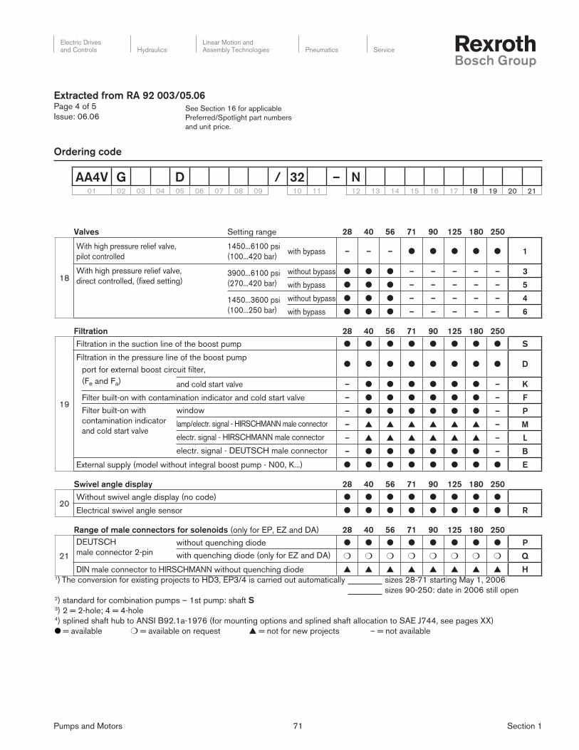
Pumps and Motors 71 Section 1
Electric Drivesand Controls Hydraulics
Linear Motion andAssembly Technologies Pneumatics Service
See Section 16 for applicable
Preferred/Spotlight part numbers
and unit price.
Extracted from RA 92 003/05.06Page 4 of 5
Issue: 06.06
Valves Setting range 28 40 56 71 90 125 180 250
18
With high pressure relief valve,
pilot controlled
1450...6100 psi
(100...420 bar)with bypass – – – ● ● ● ● ● 1
With high pressure relief valve,
direct controlled, (fi xed setting)3900...6100 psi
(270...420 bar)
without bypass ● ● ● – – – – – 3
with bypass ● ● ● – – – – – 5
1450...3600 psi
(100...250 bar)
without bypass ● ● ● – – – – – 4
with bypass ● ● ● – – – – – 6
Filtration 28 40 56 71 90 125 180 250
19
Filtration in the suction line of the boost pump ● ● ● ● ● ● ● ● S
Filtration in the pressure line of the boost pump● ● ● ● ● ● ● ● D
port for external boost circuit fi lter,
(Fe and Fa) and cold start valve – ● ● ● ● ● ● – K
Filter built-on with contamination indicator and cold start valve – ● ● ● ● ● ● – F
Filter built-on with
contamination indicator
and cold start valve
window – ● ● ● ● ● ● – P
lamp/electr. signal - HIRSCHMANN male connector – ▲ ▲ ▲ ▲ ▲ ▲ – M
electr. signal - HIRSCHMANN male connector – ▲ ▲ ▲ ▲ ▲ ▲ – L
electr. signal - DEUTSCH male connector – ● ● ● ● ● ● – B
External supply (model without integral boost pump - N00, K...) ● ● ● ● ● ● ● ● E
Swivel angle display 28 40 56 71 90 125 180 250
20Without swivel angle display (no code) ● ● ● ● ● ● ● ●
Electrical swivel angle sensor ● ● ● ● ● ● ● ● R
Range of male connectors for solenoids (only for EP, EZ and DA) 28 40 56 71 90 125 180 250
21
DEUTSCH
male connector 2-pinwithout quenching diode ● ● ● ● ● ● ● ● P
with quenching diode (only for EZ and DA) ❍ ❍ ❍ ❍ ❍ ❍ ❍ ❍ Q
DIN male connector to HIRSCHMANN without quenching diode ▲ ▲ ▲ ▲ ▲ ▲ ▲ ▲ H1) The conversion for existing projects to HD3, EP3/4 is carried out automatically ________ sizes 28-71 starting May 1, 2006
________ sizes 90-250: date in 2006 still open2) standard for combination pumps – 1st pump: shaft S3) 2 = 2-hole; 4 = 4-hole4) splined shaft hub to ANSI B92.1a-1976 (for mounting options and splined shaft allocation to SAE J744, see pages XX)
= available ❍ = available on request ▲ = not for new projects – = not available
AA4V G D / 32 – N01 02 03 04 05 06 07 08 09 10 11 12 13 14 15 16 17 18 19 20 21
Ordering code
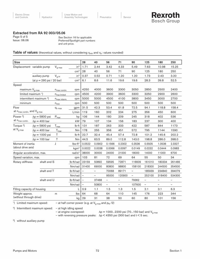
Pumps and Motors 72 Section 1
Electric Drivesand Controls Hydraulics
Linear Motion andAssembly Technologies Pneumatics Service
See Section 16 for applicable
Preferred/Spotlight part numbers
and unit price.
Size 28 40 56 71 90 125 180 250
Displacement variable pump Vg max in3 1.71 2.44 3.42 4.33 5.49 7.63 10.98 15.25
cm3 28 40 56 71 90 125 180 250
auxiliary pump Vg H in3 0.37 0.52 0.71 1.20 1.20 1.73 2.43 3.20
(at p = 290 psi / 20 bar) cm3 6.1 8.6 11.6 19.6 19.6 28.3 39.8 52.5
Speed
maximum Vg max nmax contin. rpm 4250 4000 3600 3300 3050 2850 2500 2400
limited maximum 1) nmax limited rpm 4500 4200 3900 3600 3300 3250 2900 2600
intermittent maximum 2) nmax interm. rpm 5000 5000 4500 4100 3800 3450 3000 2700
minimum nmin rpm 500 500 500 500 500 500 500 500
Flow
at nmax contin. and Vg max
qv max gpm 31.5 42.3 53.4 61.8 72.5 94.1 118.8 158.4
L/min 119 160 202 234 275 356 450 600
Power 3)
at nmax contin.
Δp = 5800 psi Pmax hp 106 144 180 209 245 318 402 536
Δp = 400 bar kW 79 107 134 156 183 237 300 400
Torque 3)
at Vg max
Δp = 5800 psi Tmax lb-ft 131 187 263 333 422 587 844 1173
Δp = 400 bar Tmax Nm 178 255 356 451 572 795 1144 1590
Δp = 1000 psi T lb-ft 22.7 32.4 45.4 57.4 72.8 101.2 145.6 202.2
Δp = 100 bar T Nm 44.5 63.5 89.0 112.8 143.0 198.8 286.0 398.0
Moment of inertia
(about drive axis)
J lbs-ft2 0.0522 0.0902 0.1566 0.2302 0.3536 0.5505 1.0536 2.3327
kgm2 0.0022 0.0038 0.0066 0.0097 0.0149 0.0232 0.0444 0.0983
Angular acceleration, max. rad/s2 38000 30000 24000 21000 18000 14000 11000 6700
Speed variation, max. rpm 103 81 72 69 64 55 50 34
Rotary stiffness shaft end S lb-ft/rad 23159 50892 59595 72871 116609 161010 180334 261466
Nm/rad 31400 69000 80800 98800 158100 218300 244500 354500
shaft end T lb-ft/rad – – 70068 89171 – 185939 234840 394079
Nm/rad – – 95000 120900 – 252100 318400 534300
shaft end U lb-ft/rad – 37468 – – 79362 – – –
Nm/rad – 50800 – – 107600 – – –
Filling capacity of housing L 0.9 1.1 1.5 1.3 1.5 2.1 3.1 6.3
Weight approx.
(without through drive)
m lbs 64 68 64 110 145 176 223 344
kg 29 31 38 50 60 80 101 156
Table of values (theoretical values, without considering ηmh and ηv: values rounded)
Extracted from RA 92 003/05.06Page 5 of 5
Issue: 06.06
1) Limited maximum speed: – at half corner power (e.g. at Vg max and pN /2)
2) Intermittent maximum speed: – at high idling speed
– at engine overspeed: Δp = 1000...2200 psi (70...150 bar) and Vg max
– with reversing pressure peaks: Δp < 4350 psi (300 bar) and t < 5 sec.
3) without auxiliary pump

Pumps and Motors 73 Section 1
Electric Drivesand Controls Hydraulics
Linear Motion andAssembly Technologies Pneumatics Service
See Section 16 for applicable
Preferred/Spotlight part numbers
and unit price.
Extracted from RA 92 050/10.97Page 1 of 6
Issue: 01.02
Variable displacement pump
for open circuits,
Axial piston, swashplate design
Model A4VSO
Sizes 40 to 250, Series 1 and 3
Nominal pressure up to 350 bar (5100 PSI)
Maximum pressure up to 400 bar (5800 PSI)
– Swashplate design
– Infi nitely variable displacement
– Good self priming suction characteristics
– Continuous operating pressure of 350 bar (5100 PSI)
– Low noise level
– Excellent service life
– Drive shaft able to accept axial and radial loading
– Good power to weight ratio
– Compact modular design
– Short control times
– Over-center design (swallow circuits)
– Swivel angle indicator standard
– Installation positional optional
For the description and operation of the various controls, see
relevant RA-sheets (see page 2).

Pumps and Motors 74 Section 1
Electric Drivesand Controls Hydraulics
Linear Motion andAssembly Technologies Pneumatics Service
See Section 16 for applicable
Preferred/Spotlight part numbers
and unit price.
Extracted from RA 92 050/10.97Page 3 of 6
Issue: 07.05
Ordering code
Hydraulic fluid / version 40 71 125 180 250 355 500 750 1000
Mineral oil (no code) l l l l l l l l lHF hydraulic fl uid (with the exception of Skydrol)
l l l l l l l – – E
High-speed version – – – – l l l – – H
High-speed version for HF fl uids – – – – l l l – – K
Version
SAE A
Axial piston unit
Swashplate design, variable, industrial design
A4VS
Charging pump 40 71 125 180 250 355 500 750 1000
Without charging pump (no code) l l l l l l l l l
Mode of operation
Pump, open circuit O
Nominal size 40 71 125 180 250 355 500 750 1000
Displacement, Vg max in3
(cm3)2.44(40)
4.33(71)
7.63(125)
10.98(180)
15.26(250)
21.66(355)
30.51(500)
45.77(750)
61.02 (1000)
Control and adjustment devices
Constant pressure control DR l l l l l l l l l DR..
Parallel pressure control DP l l l l l l l l ¢ DP.. see RA 92060
Constant fl ow control (load sensing) FR – – – FR..
Const. power control with hyperbolic oper. curve
LR l l l l l l l l ¢ LR.. see RA 92064
Manual control MA l l l l l l l – – MA..see RA 92072
Electric motor control EM l l l l l l l – – EM..
Hydraulic control, with rotary servo HW l l l l l l l l ¢ HW.. see RA 92068
Hydraulic control, volume dependent HM l l l l l l l ¢ ¢ HM..
Hydraulic control with servo/proportional valve
HS l l l l l l l l ¢ HS.. see RA 92076
Electronic control EO l l l l l l l ¢ ¢ EO..
Hydraulic control, pilot pressure dependent
HD l l l l l l l l ¢ HD.. see RA 92080
Hydraulic control, speed dependent DS1 l l l l l l l l ¢ DS.. see RE 92055
Series
Series 10 l l – – – – – – – 10*)
Series 30 – – ¢ ¢ l ¢ l ¢ l 30
Direction of rotation
As viewed from drive shaft clockwise R
counter-clockwise L
Seals
NBR (Nitrile rubber to DIN ISO 1629) with shaft seal FPM P
FPM (Fluorocarbon rubber to DIN ISO 1629) V
Shaft end
SAE parallel keyed shaft l l l l l l – – – K
SAE splined shaft l l l l l l – – – S
Metric keyed parallel shaft DIN 6885 l l l l l l l l l P
Metric splined shaft DIN 5480 l l l l l l l l l Z
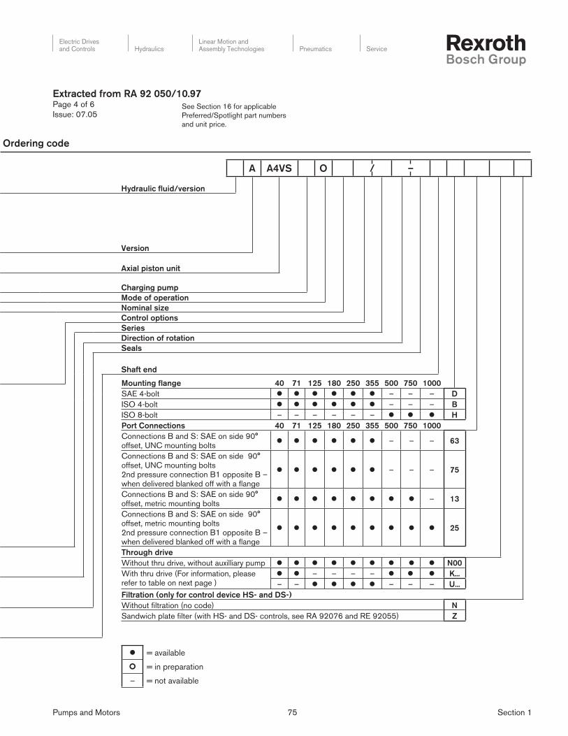
Pumps and Motors 75 Section 1
Electric Drivesand Controls Hydraulics
Linear Motion andAssembly Technologies Pneumatics Service
See Section 16 for applicable
Preferred/Spotlight part numbers
and unit price.
Extracted from RA 92 050/10.97Page 4 of 6
Issue: 07.05
A A4VS O / –
Hydraulic fluid/version
Version
Axial piston unit
Charging pump
Mode of operation
Nominal size
Control options
Series
Direction of rotation
Seals
Shaft end
l = available
¢ = in preparation
– = not available
Ordering code
Mounting flange 40 71 125 180 250 355 500 750 1000
SAE 4-bolt l l l l l l – – – D
ISO 4-bolt l l l l l l – – – B
ISO 8-bolt – – – – – – l l l H
Port Connections 40 71 125 180 250 355 500 750 1000
Connections B and S: SAE on side 90° offset, UNC mounting bolts
l l l l l l – – – 63
Connections B and S: SAE on side 90° offset, UNC mounting bolts2nd pressure connection B1 opposite B – when delivered blanked off with a fl ange
l l l l l l – – – 75
Connections B and S: SAE on side 90° offset, metric mounting bolts
l l l l l l l l – 13
Connections B and S: SAE on side 90° offset, metric mounting bolts2nd pressure connection B1 opposite B – when delivered blanked off with a fl ange
l l l l l l l l l 25
Through drive
Without thru drive, without auxilliary pump l l l l l l l l l N00
With thru drive (For information, please refer to table on next page )
l l – – – – l l l K...
– – l l l l – – – U...
Filtration (only for control device HS- and DS-)
Without fi ltration (no code) N
Sandwich plate fi lter (with HS- and DS- controls, see RA 92076 and RE 92055) Z

Pumps and Motors 76 Section 1
Electric Drivesand Controls Hydraulics
Linear Motion andAssembly Technologies Pneumatics Service
See Section 16 for applicable
Preferred/Spotlight part numbers
and unit price.
Extracted from RA 92 050/10.97Page 5 of 6
Issue: 07.05
Through-drive adapter kits to fi t U99 port plate for A4VSO
Through-drive
Code
Mount-shaft
Type
Through-Drive Kit Part Numbers
125 - 180 250
U01SAE A, 2-bolt Mount
SAE A, Spline 5/8”R902447030 R902447032
U52 SAE A, 2-Bolt Mount
SAE A-B Spline, 3/4”R902447035 R902447037
U68 (“K02”)SAE B 2-Bolt Mount
SAE B Spline, 7/8”R902447040 R902447042
U04SAE B 2-Bolt Mount
SAE B-B Spline, 1”R902447045 R902447047
U07SAE C 2-Bolt Mount
SAE C Spline, 1 1/4”R902447050 R902447051
U24SAE C 2-Bolt Mount
SAE C-C Spline, 1 1/2”R902447052 R902447053
U15SAE C, 4-Bolt Mount
SAE C Spline, 1 1/4”R902447054 R902447055
U16SAE C, 4-Bolt Mount
SAE C-C Spline, 1 1/2”R902447056 R902447057
U17SAE D 4-Bolt Mount
SAE D Spline, 1 3/4”R902447062 R902447063
U78SAE D 4-Bolt Mount
SAE F Spline, 2”R902447065 R902447066
U18SAE E 4-bolt Mount
SAE F Spline, 2”N/A R902447067
“U”-type through drives are identical in mount and fl ange to “K” type.
Kits consist of Adapter fl ange, Coupling, Mtg Bolts, O-Ring Seal.
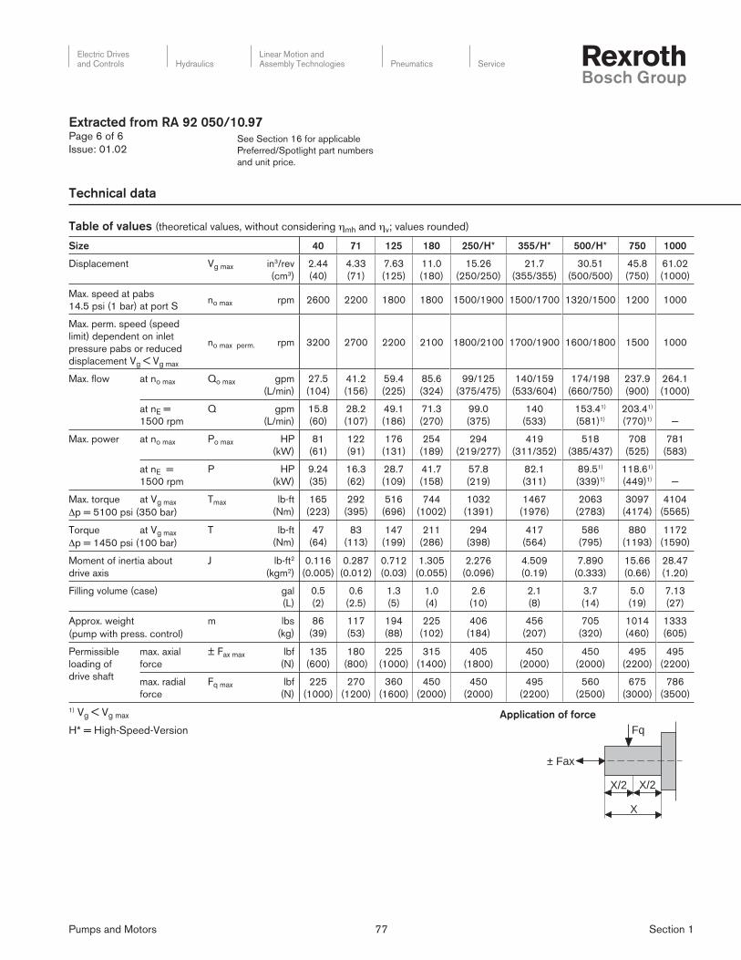
Pumps and Motors 77 Section 1
Electric Drivesand Controls Hydraulics
Linear Motion andAssembly Technologies Pneumatics Service
See Section 16 for applicable
Preferred/Spotlight part numbers
and unit price.
Size 40 71 125 180 250/H* 355/H* 500/H* 750 1000
Displacement Vg max in3/rev
(cm3)
2.44
(40)
4.33
(71)
7.63
(125)
11.0
(180)
15.26
(250/250)
21.7
(355/355)
30.51
(500/500)
45.8
(750)
61.02
(1000)
Max. speed at pabs
14.5 psi (1 bar) at port Sno max rpm 2600 2200 1800 1800 1500/1900 1500/1700 1320/1500 1200 1000
Max. perm. speed (speed
limit) dependent on inlet
pressure pabs or reduced
displacement Vg < Vg max
no max perm. rpm 3200 2700 2200 2100 1800/2100 1700/1900 1600/1800 1500 1000
Max. fl ow at no max Qo max gpm
(L/min)
27.5
(104)
41.2
(156)
59.4
(225)
85.6
(324)
99/125
(375/475)
140/159
(533/604)
174/198
(660/750)
237.9
(900)
264.1
(1000)
at nE =
1500 rpm
Q gpm
(L/min)
15.8
(60)
28.2
(107)
49.1
(186)
71.3
(270)
99.0
(375)
140
(533)
153.41)
(581)1)
203.41)
(770)1) —
Max. power at no max Po max HP
(kW)
81
(61)
122
(91)
176
(131)
254
(189)
294
(219/277)
419
(311/352)
518
(385/437)
708
(525)
781
(583)
at nE =
1500 rpm
P HP
(kW)
9.24
(35)
16.3
(62)
28.7
(109)
41.7
(158)
57.8
(219)
82.1
(311)
89.51)
(339)1)
118.61)
(449)1) —
Max. torque at Vg max Tmax lb-ft
(Nm)
165
(223)
292
(395)
516
(696)
744
(1002)
1032
(1391)
1467
(1976)
2063
(2783)
3097
(4174)
4104
(5565)Δp = 5100 psi (350 bar)
Torque at Vg max T lb-ft
(Nm)
47
(64)
83
(113)
147
(199)
211
(286)
294
(398)
417
(564)
586
(795)
880
(1193)
1172
(1590)Δp = 1450 psi (100 bar)
Moment of inertia about
drive axis
J lb-ft2
(kgm2)
0.116
(0.005)
0.287
(0.012)
0.712
(0.03)
1.305
(0.055)
2.276
(0.096)
4.509
(0.19)
7.890
(0.333)
15.66
(0.66)
28.47
(1.20)
Filling volume (case) gal
(L)
0.5
(2)
0.6
(2.5)
1.3
(5)
1.0
(4)
2.6
(10)
2.1
(8)
3.7
(14)
5.0
(19)
7.13
(27)
Approx. weight m lbs
(kg)
86
(39)
117
(53)
194
(88)
225
(102)
406
(184)
456
(207)
705
(320)
1014
(460)
1333
(605)(pump with press. control)
Permissible
loading of
drive shaft
max. axial
force
± Fax max lbf
(N)
135
(600)
180
(800)
225
(1000)
315
(1400)
405
(1800)
450
(2000)
450
(2000)
495
(2200)
495
(2200)
max. radial
force
Fq max lbf
(N)
225
(1000)
270
(1200)
360
(1600)
450
(2000)
450
(2000)
495
(2200)
560
(2500)
675
(3000)
786
(3500)
1) Vg < Vg max
H* = High-Speed-Version
Extracted from RA 92 050/10.97Page 6 of 6
Issue: 01.02
± Fax
Fq
X
X/2 X/2
Application of force
Table of values (theoretical values, without considering ηmh and ηv; values rounded)
Technical data

Pumps and Motors 78 Section 1
Electric Drivesand Controls Hydraulics
Linear Motion andAssembly Technologies Pneumatics Service
See Section 16 for applicable
Preferred/Spotlight part numbers
and unit price.
Extracted from RA 92 053/02.05Page 1 of 4
Issue: 06.06
Axial piston variable pump
for HFC Fluids (Water-Glycol)
Model AA4VSO
Sizes 125 to 355
Series 30
Nominal pressure up to 5100 PSI (350 bar)
Peak pressure up to 5800 PSI (400 bar)
– Variable displacement axial piston pump in swashplate design
for open circuit hydrostatic drives
– Especially suitable for operation with HFC fl uids
– With the approved HFC fl uids the units can be operated with
the same speeds and pressures as on mineral oil
– Infi nitely variable displacement
– Good suction characteristics
– Low noise level
– Long service life
– High power/weight ratio
– Drive shaft capable of absorbing axial and radial lloads
– Modular design
– Short control times
– Through drive and pump combinations possible
– Swivel angle indicator
– Optional mounting position
Model AA4VSO

Pumps and Motors 79 Section 1
Electric Drivesand Controls Hydraulics
Linear Motion andAssembly Technologies Pneumatics Service
See Section 16 for applicable
Preferred/Spotlight part numbers
and unit price.
Table of values 1)
Size 125 180 250
Displacement Vg ma in3/rev (cm3) 7.63 (125) 10.98 (180) 15.26 (250)
Speed2)
max. at Vg max n0 max rpm 1800 1800 1800
max. at Vg ≤ Vg max n0 max zul rpm 2200 2100 1800
Flow
at n0 max qV0 max GPM (L/min) 59.4 (225) 85.6 (324) 119 (450)
at nE=1500 min-1 qVE max GPM (L/min) 49.1 (186) 71.3 (270) 99.0 (375)
Power Δp = 5100 PSI (Δp = 350 bar)
at n0 max Po max HP (kW) 176 (131) 254 (189) 352 (262)
at nE = 1500 rpm PE max HP (kW) 146 (109) 212 (158) 294 (219)
Torque
at Vg max Δp = 5100 PSI
(Δp = 350 bar)
Tmax lb-ft
(Nm)
516
(696)
744
(1002)
1032
(1391)
Δp = 1450 PSI
(Δp = 100 bar)
T lb-ft
(Nm)
147
(199)
211
(286)
294
(398)
Moment of inertia (about drive axis) J lb-ft2 (kgm2) 0.712 (0,03) 1.305 (0,055) 2.276 (0,0959)
Angular acceleration, max. rad/s2 1225 1000 775
Torsional
stiffness
shaft K Nm/rad 277,000 339,000 542,000
shaft S Nm/rad 286,000 354,000 558,000
Case volume gal (L) 1 (4) 1.3 (5) 2.6 (10)
Weight (with pressure control) m lbs (kg) 194 (88) 225 (102) 406 (184)
1) theoretical values, without considering ηmh and ηv, values rounded2) Values are valid with inlet pressure of 14.5 PSI (1 bar) absolute at port S.
Extracted from RA 92 053/02.05Page 2 of 4
Issue: 06.06
Technical data
Operating pressure range
Inlet
Absolute pressure at port S
pabs min ............................................................................ 14.5 PSI (1 bar)
pabs max ...........................................................................435 PSI (30 bar)
For further information see page 7 under item “Filters.”
Outlet
Pressuer at port B
Nominal pressure pN ............................................5,100 PSI (350 bar)
Peak pressure pmax ...............................................5,800 PSI (400 bar)
(Pressure data to DIN 24312)
Case drain pressure
The permissible case drain pressure (housing pressure) depends
on the drive speed (see diagram).
250 125180
Size
Speed n in rpm
Cas
e dr
ain
pres
sure
PL
abs
in P
SI (
bar)
4000 3000 2000 1000 0
(4) 58
14.5
43.5
29
(3)
(2)
(1)
Max. permissible case pressure (housing pressure)
pL abs max .............................................................................58 PSI (4 bar)
These are approximate values; under certain operating conditions
a reduction in these values may be necessary.

Pumps and Motors 80 Section 1
Electric Drivesand Controls Hydraulics
Linear Motion andAssembly Technologies Pneumatics Service
See Section 16 for applicable
Preferred/Spotlight part numbers
and unit price.
Extracted from RA 92 053/02.05Page 3 of 4
Issue: 06.06
Ordering code
Axial piston unit
Swashplate design, variable, SAE version AA4VS
Type of operation
Pump, open circuit O
Size 125 180 250 355
Displacement Vg max in in3 7.63 10.98 15.26 21.66
Control device
Pressure control (see RA 92 060) l l l ¢ DR
Flow control (see RA 92 060) l l l ¢ FR
Power control with hyperbolic curve (see RA 92 064) l l l ¢ LR
Manual control (see RA 92 072) l l l ¢ MA
Electric motor control (see RA 92 072) l l l ¢ EM
Hydraulic control, volume dependent (see RA 92 076) l l l ¢ HM
Hydraulic control, with servo-proportional valve
(see RA 92 076) l l l ¢ HS
Electronic control (see RA 92 076) l l l ¢ EO
Hydraulic control, pilot pressure dependent (see RA 92 080) l l l ¢ HD
Hydraulic control, operation in parallel with mutiple pumps
(see RA 92 060) l l l ¢ DP
Electro-hydraulic control system (see RE 92 088) l l l ¢ DFE1
Series
30
Direction of rotation
Viewed on shaft endclockwise R
counter-clockwise L
Seals and fluid
NBR nitrile rubber, shaft seal PTFE Teflon, special version for HFC-Fluids F
Shaft end
Keyed parallel shaft SAE K
Splined shaft SAE S
Mounting flange
SAE 4-hole D
Ports
Pressure port B, inlet port S: SAE flange on side 90°offset, UNC threads 63
Pressure port B, inlet port S: SAE flange on side 90° offset, UNC threads,
2nd pressure port B1 opposite B (closed with blanking flange on delivery)75

Pumps and Motors 81 Section 1
Electric Drivesand Controls Hydraulics
Linear Motion andAssembly Technologies Pneumatics Service
See Section 16 for applicable
Preferred/Spotlight part numbers
and unit price.
AA4VS O / 30 – F D
Through drive 125 180 250 355
Without through drive l l l l N00
With universal through drive
Flange SAE J744 Hub for splined shaft Sealing
82-2 (A) 5/8 in (A) axial l l l l U01
82-2 (A) 3/4 in (A-B) axial l l l l U52
101-2 (B) 7/8 in (B) axial l l l l U68
101-2 (B) 1 in (B-B) axial l l l l U04
127-2 (C) 1 1/4 in (C) axial l l l l U07
127-2 (C) 1 1/2 in (C-C) axial l l l l U24
127-4 (C) 1 1/4 in (C) axial l l l l U15
127-4 (C) 1 1/2 in (C-C) axial l l l l U16
152-4 (D) 1 3/4 in (D) axial — l l l U17
152-4 (D) 2 in (F) axial — l l l U78
165-4 (E) 2 in (F) axial — — l l U18
with through drive, without coupling, without adapter flange, with cover plate for operation U99
Extracted from RA 92 053/02.05Page 4 of 4
Issue: 06.06
Axial piston unit
Type of operation
Size
Control device
Series
Direction of rotation
Seals and fluid
Shaft end
Mounting flange
Ports
l = available
¢ = in preparation
– = not available

Pumps and Motors 82 Section 1
Electric Drivesand Controls Hydraulics
Linear Motion andAssembly Technologies Pneumatics Service
See Section 16 for applicable
Preferred/Spotlight part numbers
and unit price.
Extracted from RA 92 100/10.97Page 1 of 5
Issue: 06.06
Variable displacement pump for closed
circuit axial piston, swashplate design
Model A4VSG
Sizes 40 to 1000
Series 1 and 2
Nominal pressure up to 5100 PSI (350 bar)
Peak pressure up to 5800 PSI (400 bar)
– Swashplate design
– Infi nitely variable displacement
– Reversible fl ow
– Numerous control options
– Nominal pressure 5100 psi (350 bar)
– Low noise level
– Long service life
– Drive shaft capable of absorbing axial and radial loads
– Low power / weight ratio
– Modular design
– Short control times
– Tandem pumps possible, full thru drive
– Swivel angle indicator standard
– Installation position optional
– Operation on HF fl uids permitted at derated parameters
Model A4VSG

Pumps and Motors 83 Section 1
Electric Drivesand Controls Hydraulics
Linear Motion andAssembly Technologies Pneumatics Service
See Section 16 for applicable
Preferred/Spotlight part numbers
and unit price.
Extracted from RA 92 100/10.97Page 2 of 5
Issue: 06.06
Technical data
Table of values (theoretical values, without considering hmh and hv; values rounded)
Size 40 71 125 180 250 355 500 750 1000
Displacement Vg max in3/rev(cm3/rev)
2.44(40)
4.33(71)
7.63(125)
11.0 (180)
15.26(250)
21.7 (355)
30.51(500)
45.8(750)
61.02(1000)
Max. speed nmax rpm 3700 3200 2600 2400 2200 2000 1800 1600 1600
Max. fl ow at nmax Qmax gpm (L/min)
39.1(148)
60.0(227)
85.9(325)
114.1(432)
145.3(550)
187.5(710)
237.7(900)
317.0(1200)
422.6(1600)
at nE = 1200 rpm Q gpm (L/min)
12.7(48)
22.5(85)
39.6(150)
57.0(216)
79.3(300)
112.5(426)
158.5(600)
237.8(900)
317.0(1200)
at nE 1800 rpm Q gpm (L/min)
19.0(72)
33.7(128)
59.4(2259)
85.6(324)
118.9(450)
168.8(639)
237.7(900)
— —
— —
Max. power at nmax Pmax HP(kW)
116(86)
178(132)
255(190)
339(252)
432(321)
558(414)
707(525)
943(700)
1257(933)Δp = 5100 PSI (350 bar)
at nE = 1200 rpm P HP (kW)
37.8(28)
66.9(50)
117.8(88)
169.6(126)
236.0(175)
334.7(248)
471.6(350)
707.6(525)
943.2(700)
at nE 1800 rpm P HP (kW)
56.5(42)
100.3(75)
176.7(131)
254.7(189)
353.8(263)
502.3(373)
707(525)
— —
— —
Max. torque at Vg max Tmax lb-ft(Nm)
165(223)
293(395)
516(696)
743(1002)
1032(1391)
1465(1976)
2064(2783)
3096(4174)
4127(5565)Δp = 5100 PSI (350 bar)
Torque at Vg max T lb-ft(Nm)
32(64)
57(113)
101(199)
146(286)
202(398)
287(564)
405(795)
607(1193)
809(1590)Δp = 1450 PSI (100 bar)
Moment of inertia about drive axis J lb-ft2
(kgm2)0.116
(0.005)0.287(0.012)
0.712(0.03)
1.305(0.055)
2.276(0.096)
4.509(0.19)
7.890(0.333)
15.66(0.66)
28.47(1.20)
Filling volume (case) gal (L)
0.5(2)
0.6(2.5)
1.3(5)
1.0(4)
2.6(10)
2.1(8)
3.7(14)
5.0(19)
7.13(27)
Approx. weight m lbs(kg)
104(47)
132(60)
220(100)
251(114)
472(214)
523(237)
772(350)
1102(500)
1389(630)(pump with press. control)
Permissible loading of drive shaft
max. axial force ± Fax max
lbf(N)
135(600)
180(800)
225(1000)
315(1400)
405(1800)
450(2000)
450(2000)
495(2200)
495(2200)
max. radial force Fq max
lbf(N)
225(1000)
270(1200)
360(1600)
450(2000)
450(2000)
495(2200)
562(2500)
674(3000)
787(3500)
Installation notes
Optional installation position. The pump housing must be fi lled with fl uid during commissioning and stay full when operating. In order to
obtain the lowest noise level, all connections (suction, pressure, case drain ports) must be linked by fl exible couplings to tank.
Avoid placing a check valve in the case drain line. This may be permissible in individual cases, but only after consultation with us.
Calculation of size
Vg = Geometric displacement per rev. – in3 (cm3) n = Speed rpm (rpm)Δp = Pressure differential – PSI (bar)Q = Flow – gpm (L/min)T = Torque – lb-ft (Nm)P = Power – HP (kW)ηv = Volumetric effi ciencyηmh = Mechanical-hydraulic effi ciencyηt = Total effi ciency (ηt = ηv • ηmh)
Flow Q =Vg • n • ηv
gpm ( Q = L/min )231 1000
Drive torque T =Vg • Δp
lb-ft ( T =Vg • Δp
Nm )24 • π • ηmh 24 • π • ηmh
Power P =Q • Δp
HP ( P =Q • Δp
600 • ηtkW )1714 • ηt
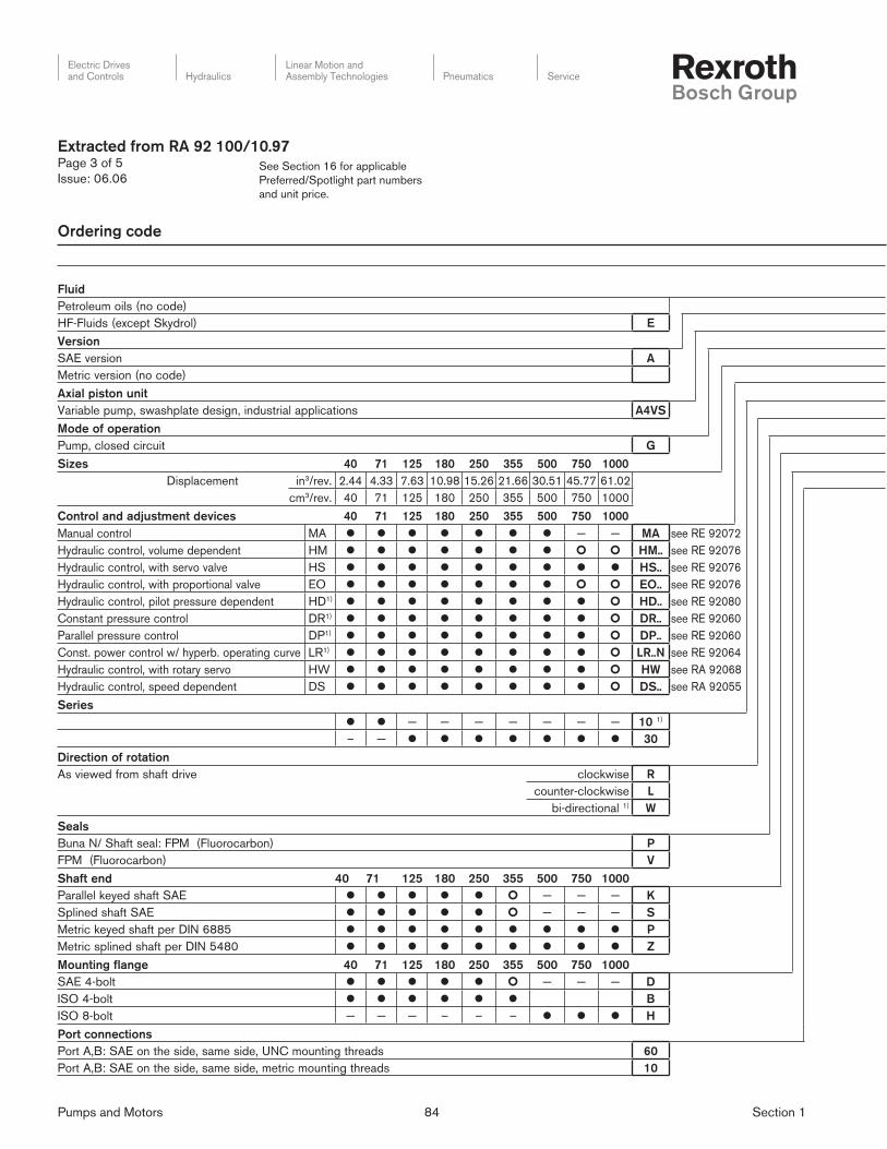
Pumps and Motors 84 Section 1
Electric Drivesand Controls Hydraulics
Linear Motion andAssembly Technologies Pneumatics Service
See Section 16 for applicable
Preferred/Spotlight part numbers
and unit price.
Fluid
Petroleum oils (no code)
HF-Fluids (except Skydrol) E
Version
SAE version A
Metric version (no code)
Axial piston unit
Variable pump, swashplate design, industrial applications A4VS
Mode of operation
Pump, closed circuit G
Sizes 40 71 125 180 250 355 500 750 1000
Displacement in3/rev. 2.44 4.33 7.63 10.98 15.26 21.66 30.51 45.77 61.02
cm3/rev. 40 71 125 180 250 355 500 750 1000
Control and adjustment devices 40 71 125 180 250 355 500 750 1000
Manual control MA l l l l l l l — — MA see RE 92072
Hydraulic control, volume dependent HM l l l l l l l ¢ ¢ HM.. see RE 92076
Hydraulic control, with servo valve HS l l l l l l l l l HS.. see RE 92076
Hydraulic control, with proportional valve EO l l l l l l l ¢ ¢ EO.. see RE 92076
Hydraulic control, pilot pressure dependent HD1) l l l l l l l l ¢ HD.. see RE 92080
Constant pressure control DR1) l l l l l l l l ¢ DR.. see RE 92060
Parallel pressure control DP1) l l l l l l l l ¢ DP.. see RE 92060
Const. power control w/ hyperb. operating curve LR1) l l l l l l l l ¢ LR..N see RE 92064
Hydraulic control, with rotary servo HW l l l l l l l l ¢ HW see RA 92068
Hydraulic control, speed dependent DS l l l l l l l l ¢ DS.. see RA 92055
Series
l l — — — — — — — 10 1)
– — l l l l l l l 30
Direction of rotation
As viewed from shaft drive clockwise R
counter-clockwise L
bi-directional 1) W
Seals
Buna N/ Shaft seal: FPM (Fluorocarbon) P
FPM (Fluorocarbon) V
Shaft end 40 71 125 180 250 355 500 750 1000
Parallel keyed shaft SAE l l l l l ¢ — — — K
Splined shaft SAE l l l l l ¢ — — — S
Metric keyed shaft per DIN 6885 l l l l l l l l l P
Metric splined shaft per DIN 5480 l l l l l l l l l Z
Mounting flange 40 71 125 180 250 355 500 750 1000
SAE 4-bolt l l l l l ¢ — — — D
ISO 4-bolt l l l l l l B
ISO 8-bolt — — — – – – l l l H
Port connections
Port A,B: SAE on the side, same side, UNC mounting threads 60
Port A,B: SAE on the side, same side, metric mounting threads 10
Extracted from RA 92 100/10.97Page 3 of 5
Issue: 06.06
Ordering code
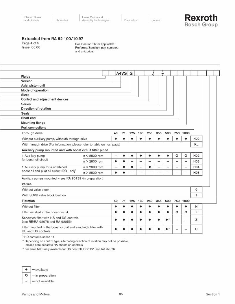
Pumps and Motors 85 Section 1
Electric Drivesand Controls Hydraulics
Linear Motion andAssembly Technologies Pneumatics Service
See Section 16 for applicable
Preferred/Spotlight part numbers
and unit price.
*) HD control is series 11.1) Depending on control type, alternating direction of rotation may not be possible,
please note separate RA sheets on controls.2) For sizes 500 (only available for DS control), HS/HS1 see RA 92076
Fluids
Version
Axial piston unit
Mode of operation
Sizes
Control and adjustment devices
Series
Direction of rotation
Seals
Shaft end
Mounting flange
Port connections
Extracted from RA 92 100/10.97Page 4 of 5
Issue: 06.06
A4VS G / –
Through drive 40 71 125 180 250 355 500 750 1000
Without auxilliary pump, withouth through drive l l l l l l l l l N00
With through drive (For information, please refer to table on next page) K...
Auxiliary pump mounted and with boost circuit filter piped
1 Auxiliary pump
for boost oil circuit
n < 2800 rpm — l l l l l l ¢ ¢ H02
n > 2800 rpm l l — — — — — — — H03
1 Auxiliary pump for a combined
boost oil and pilot oil circuit (EO1 only)
n < 2800 rpm — l l – l — — — — H04
n > 2800 rpm l l — — — — — — — H05
Auxiliary pumps mounted – see RA 90139 (in preparation)
Valves
Without valve block 0
With SDVB valve block built on 9
Filtration 40 71 125 180 250 355 500 750 1000
Without filter l l l l l l l l l N
Filter installed in the boost circuit l l l l l l l ¢ ¢ F
Sandwich filter with HS and DS controls
(see RE/RA 92076 and RA 92055)l l l l l l l 2) — — Z
Filter mounted in the boost circuit and sandwich filter with
HS and DS controlsl l l l l l l 2) — — U
l = available
¢ = in preparation
– = not available

Pumps and Motors 86 Section 1
Electric Drivesand Controls Hydraulics
Linear Motion andAssembly Technologies Pneumatics Service
See Section 16 for applicable
Preferred/Spotlight part numbers
and unit price.
Through drive ordering codes 40 71 125 180 250 355 500 750 1000
Without auxiliary pump, without through drive l l l l l l l l l N00
With through drive for mounting of axial piston unit, gear or radial piston pump
Flange Hub/shaft to accept
ISO 125, 4-bolt Splined shaft 32x2x30x14x9g A4VSO/H/G 40 l l l l l l l ¢ ¢ K31
ISO 125, 4-bolt splined 32x2x14x9g A4VSO/H/G 40 l l l l l ¢ l ¢ ¢ K31
ISO 140, 4-bolt splined 40x2x18x9g A4VSO/H/G 71 — l l l l l l ¢ ¢ K33
ISO 160, 4-bolt splined 50x2x24x9g A4VSO/H/G 125 — — l l l ¢ l ¢ ¢ K34
ISO 160, 4-bolt splined 50x2x24x9g A4VSO/G 180 — — — l l ¢ l ¢ ¢ K34
ISO 224, 4-bolt splined 60x2x28x9g A4VSO/H/G 250 — — — — l ¢ l ¢ ¢ K35
ISO 224, 4-bolt splined 70x3x22x9g A4VSO/G 355 — — — — — l ¢ ¢ ¢ K77
ISO 315, 8-bolt splined 80x2x38x9g A4VSO/G 500 — — — — — — l l ¢ K43
ISO 400, 8-bolt splined 90x3x28x9g A4VSO/G 750 — — — — — — — ¢ ¢ K76
127-4 (SAE C, 4-bolt) splined 32-4 (SAE C) AA4VSO/G 40 ¢ ¢ ¢ ¢ ¢ ¢ — — — K15
127-4 (SAE C, 4-bolt) splined 38-4 (SAE C-C) AA4VSO/G 71 ¢ ¢ l ¢ ¢ ¢ — — — K16
152-4 (SAE D, 4-bolt) splined 44-4 (SAE D) AA4VSO/G 125 — — l ¢ ¢ ¢ — — — K17
152-4 (SAE D, 4-bolt) splined 50-4 (SAE F) AA4VSO/G 180 — — — ¢ ¢ ¢ — — — K78
165-4 (SAE E, 4-bolt) splined 50-4 (SAE F) AA4VSO/G 250 — — — — l ¢ — — — K18
82-2 (SAE A, 2-bolt) keyed 19-1 (SAE A-B) AA10VSO 18 ¢ ¢ ¢ ¢ ¢ ¢ — — — K40
101-2 (SAE B, 2-bolt) keyed 22-1 (SAE B) * AA10VSO 28 l l l ¢ ¢ ¢ — — — K03
101-2 (SAE B, 2-bolt) keyed 25-1 (SAE B-B) * AA10VSO 45 ¢ ¢ ¢ ¢ ¢ ¢ — — — K05
127-2 (SAE C, 2-bolt) keyed 32-1 (SAE C) * AA10VSO 71 — ¢ ¢ ¢ l ¢ — — — K08
127-2 (SAE C, 2-bolt) keyed 38-1 (SAE C-C) * AA10VSO 100 — — ¢ ¢ ¢ ¢ — — — K38
152-4 (SAE D, 4-bolt) keyed 44-1 (SAE D) * AA10VSO 140 — — ¢ ¢ ¢ ¢ — — — K21
82-2 (SAE A, 2-bolt) splined 5/8" 16-4 (SAE A) G2 / GC2/GC3-1X l l l l l l l ¢ ¢ K01
82-2 (SAE A, 2-bolt) splined 3/4" 19-4 (SAE A-B) A10VSO 18 l l l l l l l ¢ ¢ K52
101-2 (SAE B) 22-4 (SAE B) G3, G4, A10VSO 28 l l l l l l l l ¢ K68
101-2 (SAE B) splined 25-4 (SAE B-B) GC4-1X, A10VO 45 ¢ ¢ l ¢ ¢ l ¢ ¢ ¢ K04
101-2 (SAE B) splined 32-4 (SAE C) GC5-1X l l l ¢ l ¢ ¢ ¢ ¢ K06
127-2 (SAE C) splined 32-4 (SAE C) A10VO 71 ¢ ¢ ¢ ¢ ¢ ¢ ¢ ¢ ¢ K07
127-2 (SAE C) splined 38-4 (SAE C-C) GC6-1X, A10VO 100 — ¢ l l l ¢ ¢ ¢ ¢ K24
152-4 (SAE D) splined 44-4 (SAE D) A10VO 140 ¢ ¢ ¢ ¢ ¢ ¢ ¢ ¢ ¢ K17
Ø 63 (mm) metric, 4-bolt, keyed Ø 25 (mm) R4 l l l ¢ l ¢ ¢ ¢ ¢ K57
101-2 (SAE B, 2-bolt) splined 7/8" R-shaft (SAE B med.) A10VO 28...R, PVV 1 & 2 ¢ ¢ ¢ ¢ ¢ ¢ ¢ ¢ ¢ KA3
101-2 (SAE B, 2-bolt) splined 1" R-shaft (SAE BB) A10VO 45...R ¢ ¢ ¢ ¢ ¢ ¢ ¢ ¢ ¢ KA4
127-2 (SAE C, 2-bolt) splined 1-1/4", R-shaft (SAE C) A10VO 71...R, PVV 4 & 5 ¢ ¢ ¢ ¢ ¢ ¢ ¢ ¢ ¢ KA5
with through drive shaft, without coupler, without intermediate flange, with cover l l l ¢ l l l l ¢ K99
Through drive / Combination pumps
1. If a second Brueninghaus Hydromatik pump is to be mounted at the factory, the two ordering codes have to be connected with a "+".
Ordering code of the fi rst pump + ordering code of the second pump
SAE Example: AA4VSG 125 EO1/22R – PSD60K16ON + AA4VSG 71 HM1/10R – PSD60N000N
Metric Example: A4VSG 125 EO1/22R – PPB10K339F + A4VSG 71 HM1/10R – PZB10N000N
2. Please check with the factory if a gear pump or radial piston pump is to be mounted at the factory.
* Not for new projects. Permitted with reduced through drive torque only.
Extracted from RA 92 100/10.97Page 5 of 5
Issue: 06.06
Ordering code

Pumps and Motors 87 Section 1
Electric Drivesand Controls Hydraulics
Linear Motion andAssembly Technologies Pneumatics Service
See Section 16 for applicable
Preferred/Spotlight part numbers
and unit price.
Extracted from RA 92 105/05.04Page 1 of 4
Issue: 06.06
Axial piston-compact unit
Model AA4CSG (A4CSG)
Sizes 250 to 750
Series 3
Nominal pressure up to 5100 PSI (350 bar)
Peak pressure up to 5800 PSI (400 bar)
– Axialpiston pump-variable displacement, swashplate design for hydrostatic drives in closed circuits.
– The fl ow is proportional to input speed and displacement. It can be infi nitely varied by adjustment of the swashplate.
– The necessary boostpump and all required controlvalves are integrated.
– One common auxiliary pump for boost and EP-control pressure
– Compact design (extremely short in length)
– Favorable power to weight ratio
– Low noise level
– Long service life
– High effi ciency
– New electro-hydr. control EP with proportional solenoid and zero displacement position at power loss (fail safe function)
– Throughdrive for multiple pumpcombinations also possible with integrated boost pump
– Full through drive capability, tandems of same size possible
– For further information on control- and regulating devices see separate data sheets RA 92 076 and RA 92 080
Model AA4CSG

Pumps and Motors 88 Section 1
Electric Drivesand Controls Hydraulics
Linear Motion andAssembly Technologies Pneumatics Service
See Section 16 for applicable
Preferred/Spotlight part numbers
and unit price.
Extracted from RA 92 105/05.04Page 2 of 4
Issue: 06.06
Ordering code
Version 250 355 500 750 A
SAE version l l — —
Metric version (no code) — — l l
Axial piston unit
Compact unit, swashplate design, variable displacementNominal pressure 5100 psi (350 bar), peak pressure 5800 psi (400 bar)
A4CS
Type of operation
Pump, closed circuit operation G
Size 250 355 500 750
Displacement Vg max
in3 15.26 21.66 30.51 45.77
(cm3) (250) (355) (500) (750)
Control and adjustment devices
Hydr. adjustment, control volume dependent HM ¢ ¢ ¢ ¢ HM..
}see
RA 92076Hydr. adjustment with servo-/ proportional valve HS ¢ ¢ ¢ ¢ HS..
Electronic control EO ¢ ¢ ¢ ¢ EO..
Hydr. control, pilot pressure dependent HD ¢ l l ¢ HD.. see RA 92080
Electro-hydraulic control with proportional solenoid EP l l l l EP.. see RA 92084
Series
30
Direction of rotation
viewing at shaft end clockwise R
counter-clockwise L
Seals
FKM (Fluorcarbon rubber) V
Shaft end 250 355 500 750
SAE parallel keyed shaft l l — — K
SAE splined shaft l — — — S
SAE splined shaft with run out spline — l — — R
Metric keyed parallel shaft DIN 6885 — — l l P
Metric splined shaft DIN 5480 — — l l Z
Mounting flange
4-hole to SAE J744 (ISO 3019-1) l l — — D
8-hole to ISO 3019-2 — — l l H
Port connections
Ports A,B: SAE flanged opposite sides UNC threadedPort S: SAE flanged on side 90o offset } bolt holes
l l — — 85
Ports A,B: SAE flanged opposite sides metric threadedPort S: SAE flanged on side 90o offset } bolt holes
— — l l 35
Boost pump 250 355 500 750
with integrated boost pump l l l l F
without integrated boost pump ¢ ¢ l ¢ K
l = available ¢ = in preparation — = not available

Pumps and Motors 89 Section 1
Electric Drivesand Controls Hydraulics
Linear Motion andAssembly Technologies Pneumatics Service
See Section 16 for applicable
Preferred/Spotlight part numbers
and unit price.
Extracted from 92 105/05.04Page 3 of 4
Issue: 06.06
Version
Axial piston unit
Type of operation
Size
Control and adjustment device
Series
Direction of rotation
Seals
Shaft end
Mounting flange
Port connections
Boost pump
A4CS G / 30 – V
Through drive 250 355 500 750
prepared for through drive, no coupling, no adapter flange, closed with cover l l l l 99
with through drive for mounting of second pump (for further options see page 18)
Flange SAE J744 shaft coupling splined SAE J744 to mount
127-41) (C) 32-4 11/4 in 14T (C) AA4VSO/G 40 ¢ ¢ ¢ ¢ 15
127-41) (C) 38-4 11/2 in 17T (C-C.) AA4VSO/G 71 ¢ ¢ ¢ ¢ 16
152-41) (D) 44-4 13/4 in 13T (D) AA4VSO/G 125 l l l ¢ 17
152-41) (D) 50-4 2 in 15T (F) AA4VSO/G 180 ¢ ¢ ¢ ¢ 78
165-41) (E) 50-4 2 in 15T (F) AA4CSG, AA4VSO/G 250 ¢ ¢ ¢ ¢ 18
165-41) (E) 50-4 2 in 15T (F) AA4CSG, AA4VSO/G 355 – ¢ ¢ ¢ 18
Flange ISO 3019-2 (metr.) shaft coupling splined DIN 5480 to mount
315, 8-hole W 0x3x30x25x9g A4CSG, A4VSO/G 500 – – l ¢ 43
400, 8-hole W 0x3x30x28x9g A4CSG, A4VSO/G 750 – – – ¢ 76
Flange SAE J 744 shaft coupling splined SAE J744 to mount
82-21) (A) 16-4 5/8 in 9T (A) AZPF, PGF2 l l l ¢ 01
82-21) (A) 19-4 3/4 in 11T (A-B) A10VSO 10, 18 ¢ ¢ ¢ ¢ 52
101-21) (B) 22-4 7/8 in 13T (B) (A)A10V(S)O 28, PGF3, AZPN/G l l l ¢ 68
101-21) (B) 25-4 1 in 15T (B-B) (A)A10V(S)O 45, PGH4 ¢ ¢ l ¢ 04
127-21) (C) 32-4 11/4 in 14T (C) (A)A10V(S)O 71 l l l ¢ 07
127-21) (C) 38-4 11/2 in 17T (C-C) (A)A10V(S)O 100, PGH5 ¢ ¢ ¢ ¢ 24
152-41) (D) 44-4 13/4 in 13T (D) (A)A10V(S)O 140 l l l ¢ 171) 2 = 2-bolt; 4 = 4-bolt to SAE J744
Valves
Integrated: boost-, control pressure relief- and flushing valve; direct operated mainline relief valves 2) ¢ ¢ ¢ ¢ 3
Integrated: boost-, control pressure relief- and flushing valve; pilot operated mainline relief valves 2) l l l l 42) crossover relief valves
Filtration
without filter l l l l N
with threaded connection for filter in boost circuit l l l l D
with built on filter (optical-electr. dirt indicator) in boost circuit l l l ¢ M
with threaded connection f. filter in boost circuit (D) a. sandwichplate filter for HS-control (see RA 92076) ¢ ¢ – – Z
with built on filter in boost circuit (M) and sandwichplate filter for HS-control (see RA 92076) ¢ ¢ – – U

Pumps and Motors 90 Section 1
Electric Drivesand Controls Hydraulics
Linear Motion andAssembly Technologies Pneumatics Service
See Section 16 for applicable
Preferred/Spotlight part numbers
and unit price.
Table of values (theoretical values, without considering hmh und hv; values rounded)
Size 250 355 500 750
Displacement Variable pump Vg max in3
(cm3)15.26(250)
21.7(355)
30.51(500)
45.8(750)
integr. boost pump Vg H in3
(cm3)3.84(63)
4.88(80)
5.98(98)
8.72(143)
Drive speed max. speed nmax rpm 2200 2000 1800 1600
min. speed nmin rpm 800 800 800 800
Max. fl ow (variable pump) at nmax qv max gpm(L/min)
145.3(550)
187.6(710)
237.8(900)
317.0(1200)
at nE = 1200 rpm qv 1200 gpm(L/min)
79.3(300)
112.5(426)
158.5(600)
237.8(900)
at nE = 1800 rpm qv 1800 gpm(L/min)
118.9(450)
168.8(639)
237.7(900)
——
Max. power (variable pump, Δp = 5100 psi [350 bar] without boost pump)
at nmax Pmax HP(kW)
432(321)
558(414)
707(525)
943(700)
at nE = 1200 rpm P1200 HP(kW)
236(175)
334.7(248)
471.6(350)
707.6(525)
at nE = 1800 rpm P1800 HP(kW)
353.8(263)
502.3(373)
707(525)
——
Max. torque at Vg max (variable pump without boost pump)
Δp = 5100 psi(350 bar)
Tmax lb-ft(Nm)
1032(1391)
1465(1976)
2064(2783)
3096(4174)
Δp = 1450 psi(100 bar)
T lb-ft(Nm)
295(398)
416(564)
586(795)
879(1193)
Moment of inertia about drive axis J lb-ft2
(kgm2)2.276(0.96)
4.509(0.19)
7.890(0.333)
15.66(0.66)
Torsional stiffness Shaft end K / P lb-ft/rad(kNm/rad)
326491(443)
599918(814)
843865(1145)
1370820(1860)
Shaft end S / R / Z lb-ft/rad(kNm/rad)
271216(368)
350075(475)
891033(1209)
1335444(1812)
Case volume gal(L)
2.64(10)
2.11(8)
3.70(14)
5.02(19)
Weight approx.. (Pump with EP-control and integrated boost pump)
m lbs(kg)
472(214)
523(237)
772(350)
1102(500)
Permissible forces on drive shaft
Size 250 355 500 750
Permissible radial force Fq max lbf(N)
450(2000)
495(2200)
562(2500)
674(3000)
Permissible axial force ± Fax max lbf(N)
405(1800)
450(2000)
450(2000)
495(2200)
Application of forces
± Fax
Fq
X
X/2 X/2
Vg = geometr. displacement per revolution in in3 (cm3)
Δp = Pressure differential in PSI (bar)
n = Drive speed in rpm (min-1)
ηv = Volumetric efficiency
ηmh = Mechanical-hydraulic efficiency
ηt = Overall efficiency (ηt = ηv • ηmh)
Determination of size
Extracted from RA 92 105/05.04Page 4 of 4
Issue: 06.06
Ordering code
Flow qV =Vg • n • ηv
gpm ( qV =Vg • n • ηv
L/min )231 1000
Drive torque T =Vg • Δp
lb-ft ( T =1.59 • Vg • Δp
Nm )24 • π • ηmh 100 • ηmh
Power P =qV • Δp
HP ( P =2π • T• n
=qV • Δp
kW )1714 • ηt 60,000 600 • ηt

Pumps and Motors 91 Section 1
Electric Drivesand Controls Hydraulics
Linear Motion andAssembly Technologies Pneumatics Service
See Section 16 for applicable
Preferred/Spotlight part numbers
and unit price.
Extracted from RA 92 500/06.04Page 1 of 4
Issue: 06.06
Variable displacement pump
for open circuits,
Axial piston, swashplate design
Model AA11VO
Sizes 40...260
Series 1
Nominal pressure 5100 psi (350 bar)
Peak pressure 5800 psi (400 bar)
– Variable displacement axial piston pump of swashplate design
for hydrostatic drives in open circuit hydraulic system
– Designed primarily for use in mobile applications
– The pump operates under self-priming conditions, with tank
pressurization, or with an optional built-in charge pump (impeller)
– A comprehensive range of control options is available matching
any application requirement
– Power control option is externally adjustable, even when the
pump is running
– The through drive is suitable for adding gear pumps and axial
piston pumps up to the same, i.e. 100% through drive
– The output fl ow is proportional to the drive speed and infi nitely
variable between maximum and zero

Pumps and Motors 92 Section 1
Electric Drivesand Controls Hydraulics
Linear Motion andAssembly Technologies Pneumatics Service
See Section 16 for applicable
Preferred/Spotlight part numbers
and unit price.
Ordering code
Axial piston unit
Swashplate design, variable displacement, SAE version AA11V
Charge pump (impeller) 40 60 75 95 130 145 190 260
without charge pump (no code) ● ● ● ● ● ● ● ●
with charge pump – – – – ● ● ● ● L
Operation
Pump, open circuit O
Size 40 60 75 95 130 145 190 260
Displacement Vg max cm3/rev. 42 58.5 74 93.5 130 145 193 260
in3/rev. 2.56 3.57 4.52 5.71 7.93 8.84 11.78 15.87
Control device 40 60 75 95 130 145 190 260
Power control LR ● ● ● ● ● ● ● ● LR
with override cross-sensing negative LR C ● ● ● ● ● ● ● ● LR . C
high pressure related negative LR3 ● ● ● ● ● ● ● ● LR3
pilot pressure related negative LG1 ● ● ● ● ● ● ● ● LG1
positive LG2 ● ● ● ● ● ● ● ● LG2
electrical 12V negative LE1 ❍ ❍ ❍ ● ● ● ● ● LE1
24V negative LE2 ❍ ● ● ● ● ● ● ● LE2
with pressure cut-off D ● ● ● ● ● ● ● ● L . D..
hydraulic 2-stage E ● ● ● ● ● ● ● ● L.E..
hydraulic remote controlled G ● ● ● ● ● ● ● ● L . . G .
with load sensing S ● ● ● ● ● ● ● ● L . . . S
electr. prop. override, 24V neg. S2 ❍ ❍ ❍ ● ● ● ● ● L...S2
hydr. prop. override, negative S5 ❍ ❍ ❍ ● ● ● ● ● L . . . S5
with stroke limiter negative Δp = 365 psi (25 bar) H1 ● ● ● ● ● ● ● ● L . . . H1
characteristic Δp = 145 psi (10 bar) H5 ● ● ● ● ● ● ● ● L . . . H5
positive Δp = 365 psi (25 bar) H2 ● ● ● ● ● ● ● ● L . . . H2
characteristic Δp = 145 psi (10 bar) H6 ● ● ● ● ● ● ● ● L . . . H6
positive characteristic U = 12 V U1 ● ● ● ● ● ● ● ● L . . . U1
U = 24 V U2 ● ● ● ● ● ● ● ● L . . . U2
Pressure control DR ● ● ● ● ● ● ● ● DR
with load sensing DRS ● ● ● ● ● ● ● ● DRS
remote controlled DRG ● ● ● ● ● ● ● ● DRG
for parallel operation DRL ● ● ● ● ● ● ● ● DRL
Hydraulic control Δp = 145 psi (10 bar) HD1 ● ● ● ● ● ● ● ● HD1
pilot pressure related (pos. charac.) Δp = 365 psi (25 bar) HD2 ● ● ● ● ● ● ● ● HD2
with pressure cut-off D ● ● ● ● ● ● ● ● HD. D
with pressure cut-off, remote controlled G ❍ ● ❍ ❍ ❍ ❍ ● ● HD. G
Electrical control U = 12 V EP1 ● ● ● ● ● ● ● ● EP1
with proportional solenoid (pos. characteristic) U = 24 V EP2 ● ● ● ● ● ● ● ● EP2
with pressure cut-off D ● ● ● ● ● ● ● ● EP. D
with pressure cut-off, remote controlled G ● ● ● ● ● ● ● ● EP. G
In case of controls with several additional functions, observe the order of the columns, only one option per column is possible
(e.g. LRDCH2).
The following combinations are not available for the power control:
LRDS2, LRDS5, L...GS, L...GS2, L...GS5, L...EC and the combination L...DG in connection with the stroke limiters H1, H2, H5, H6,
U1 and U2.
● = available
❍ = available on request
– = not available

Pumps and Motors 93 Section 1
Electric Drivesand Controls Hydraulics
Linear Motion andAssembly Technologies Pneumatics Service
See Section 16 for applicable
Preferred/Spotlight part numbers
and unit price.
Axial piston unit
Charge pump
Operation
Size
Control device
Series
1
Index
size 40...130 0
size 145...260 1
Direction of rotation
viewed on shaft end clockwise R
counter-clockwise L
Seals
NBR (Buna-N), shaft seal in FKM (fl uorocarbon) N
Shaft end (perm. input torques see page 7) 40 60 75 95 130 145 190 260
Splined shaft ANSI B92.1a–1976 for single pump ● ● ● ● ● ● ● ● S
for combination pump ● ● ● –1) –1) –1) ● ● T
Cylindrical shaft with key DIN 6885 ● ● ● ● ● ● ● ● P
Mounting fl ange 40 60 75 95 130 145 190 260
SAE J744 – 2-hole ● ● – – – – – – C
SAE J744 – 4-hole – – ● ● ● ● ● ● D
SAE J617 2) (SAE 3) – – – ● ● ● ● – G
Service line ports 40 60 75 95 130 145 190 260
Pressure and suction port on opposite sides (SAE), ● ● ● ● ● ● ● ● 62
with UNC fastening threads
Through drive (see page 56 for attachments)
Flange SAE J744 3) Splined shaft coupler 40 60 75 95 130 145 190 260
– – ● ● ● ● ● ● ● ● N00
82-2 (A) 5/8in 9T 16/32DP (A) ● ● ● ● ● ● ● ● K01
3/4in 11T 16/32DP (A-B) ❍ ● ❍ ● ● ● ❍ ❍ K52
101-2 (B) 7/8in 13T 16/32DP (B) ● ● ● ● ● ● ● ● K02
1in 15T 16/32DP (B-B) ● ● ● ● ● ● ● ● K04
127-2 (C) 4) 1 1/4in 14T 12/24DP (C) – ● ● ● ● ● ● ● K07
1 1/2in 17T 12/24DP (C-C) – – – ● ● ● ● ● K24
152-4 (D) 1 1/4in 14T 12/24DP (C) – – ● ● ● ● ● ● K86
1 3/4in 13T 8/16DP (D) – – – – ● ● ● ● K17
165-4 (E) 1 3/4in 13T 8/16DP (D) – – – – – – ● ● K72
Swivel angle indicator (page 57) 40 60 75 95 130 145 190 260
without (no code) ● ● ● ● ● ● ● ●
with optical swivel angle indicator ● – ● ● ● ● ● ● V
with electrical swivel angle sensor ● – ● ● ● ● ● ● R
Male connectors for solenoids 5) (page 58) 40 60 75 95 130 145 190 260
DEUTSCH DT04-2P-EP04 (2-pole), molded to the solenoid coil ● ● ● ● ● ● ● ● P
Hirschmann according to DIN EN 175 301-803-A ● ● ● ● ● ● ● ● H
(not for new projects)
AA11V O / 1 – N 62 – 6)
1) S-shaft suitable for combination pump! 4) Size 190 and 260 with 2 + 4-hole fl ange2) To fi t the fl ywheel housing of the combustion engine 5) Male connector without bidirectional surpressor diode3) 2 2-hole; 4 4-hole6) no code = standard version, S = special version, K = combination with mounting part or mounting pump

Pumps and Motors 94 Section 1
Electric Drivesand Controls Hydraulics
Linear Motion andAssembly Technologies Pneumatics Service
See Section 16 for applicable
Preferred/Spotlight part numbers
and unit price.
Technical Data
Extracted from RA 92 500/06.04Page 4 of 4
Issue: 06.06
Value table (theoretical values, without effi ciencies and tolerances; values rounded)
Size AA11VO 40 60 75 95 130 145 190 260
AA11VLO (with charge pump) 130 145 190 260
Displacement Vg max In3/rev. 2.56 3.57 4.52 5.71 7.93 8.84 11.78 15.87 7.93 8.84 11.78 15.87
cm3/rev. 42 58.5 74 93.5 130 145 193 260 130 145 193 260
Vg min In3/rev. 0 0 0 0 0 0 0 0 0 0 0 0
Speed
maximum at Vg max 1)
nmax rpm 3000 2700 2550 2350 2100 2200 2100 1800 2500 2) 2500 2) 2500 2) 23002)
maximum at Vg ≤ Vg max 3) nmax1 rpm 3500 3250 3000 2780 2500 2500 2500 2300 2500 2500 2500 2300
Flow 4) gpm 33.3 41.7 49.9 58.1 72.1 84.3 107 123.6 85.9 95.9 127.6 158
at nmax and Vg max
qV max L/min 126 158 189 220 273 319 405 468 325 363 483 598
Power at qV max hp 99.2 123.4 147.5 171.7 213.2 249.4 316.5 366.1 254.8 283 376.8 468
and Δp = 5100 psi (350 bar) Pmax
kW 74 92 110 128 159 186 236 273 190 211 281 349
Torque at Vg max lb-ft 172.6 240.4 303.9 384.3 534 596 792.9 1068 534 596 792.9 1068
and Δp = 5100 psi (350 bar) Tmax
Nm 234 326 412 521 724 808 1075 1448 724 808 1075 1448
Mass moment of inertia lbs-ft2 0.1139 0.1946 0.2729 0.4105 0.7546 0.8092 1.3052 2.0835 0.7997 0.8543 1.3692 2.1238
around drive axis J kgm2 0.0048 0.0082 0.0115 0.0173 0.0318 0.0341 0.055 0.0878 0.0337 0.036 0.0577 0.0895
Rotational vibration 4)
Angular acceleration, max. α rad/s2 22000 17500 15000 13000 10500 9000 6800 4800 10500 9000 6800 4800
Speed variation, max. Δn rpm 85 73 68 63 57 49 37 28 57 49 37 28
Frequency limit flimit Hz 788 731 675 626 563 563 563 518 563 563 563 518
Rotary stiffness Shaft end S lb-ft/rad 43035 63658 75173 128117 174700 174700 191599 259628 174700 174700 191599 259628
Nm/rad 58347 86308 101921 173704 236861 236861 259773 352009 236861 236861 259773 352009
Shaft end T lb-ft/rad 54931 75556 92640 – – – 222691 418282 – – 222691 418282
Nm/rad 74476 102440 125603 – – – 301928 567115 – – 301928 567115
Shaft end P lb-ft/rad 64512 79574 105548 14883 230417 230417 282702 482244 230417 230417 282702 482244
Nm/rad 87467 107888 143104 196435 312403 312403 383292 653835 312403 312403 383292 653835
Filling volume gal 0.29 0.36 0.49 0.55 0.77 0.77 1.0 1.22 0.77 0.77 1.0 1.22
L 1.1 1.35 1.85 2.1 2.9 2.9 3.8 4.6 2.9 2.9 3.8 4.6
Weight (approx.) lbs 71 88 99 117 145 168 209 276 159 161 229 304
m
kg 32 40 45 53 66 76 95 125 72 73 104 138
1) The values apply at absolute pressure (pabs) 14.5 psi (1 bar) at the suction port S and mineral hydraulic fl uid.2) The values apply at absolute pressure (pabs) of at least 12 psi (0.8 bar) at the suction port S and mineral hydraulic fl uid.3) The values apply at Vg ≤ Vg max or in case of an increase in the inlet pressure pabs at the suction port S (see diagram page 5)4) The permissible angular acceleration or speed variation only applies for single pumps, not for combi pumps. The load on connection parts (e.g. through drive) must be taken into account additionally. At f < flimit the Δn specifi ed in the table is permissible.
At f > flimit the permissible angular acceleration α specifi ed in the table limits the value of the speed variation: Δnperm = 3.04 • α/f.
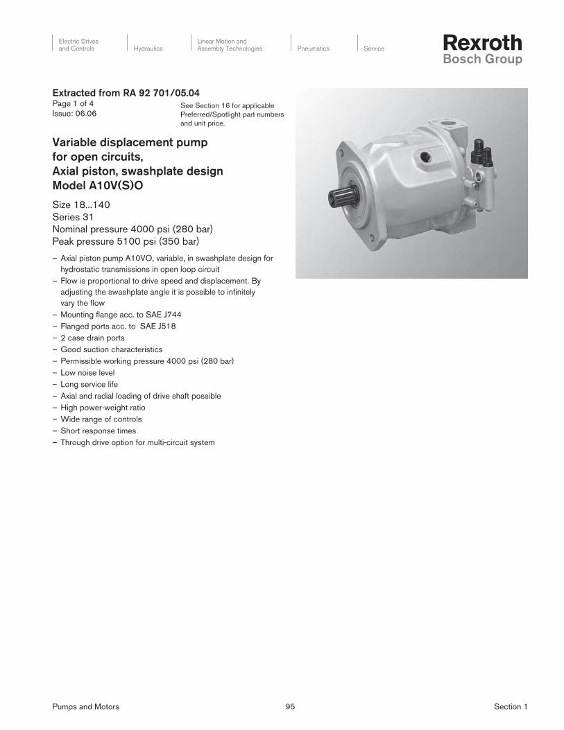
Pumps and Motors 95 Section 1
Electric Drivesand Controls Hydraulics
Linear Motion andAssembly Technologies Pneumatics Service
See Section 16 for applicable
Preferred/Spotlight part numbers
and unit price.
Extracted from RA 92 701/05.04Page 1 of 4
Issue: 06.06
Variable displacement pump
for open circuits,
Axial piston, swashplate design
Model A10V(S)O
Size 18...140
Series 31
Nominal pressure 4000 psi (280 bar)
Peak pressure 5100 psi (350 bar)
– Axial piston pump A10VO, variable, in swashplate design for
hydrostatic transmissions in open loop circuit
– Flow is proportional to drive speed and displacement. By
adjusting the swashplate angle it is possible to infi nitely
vary the fl ow
– Mounting fl ange acc. to SAE J744
– Flanged ports acc. to SAE J518
– 2 case drain ports
– Good suction characteristics
– Permissible working pressure 4000 psi (280 bar)
– Low noise level
– Long service life
– Axial and radial loading of drive shaft possible
– High power-weight ratio
– Wide range of controls
– Short response times
– Through drive option for multi-circuit system
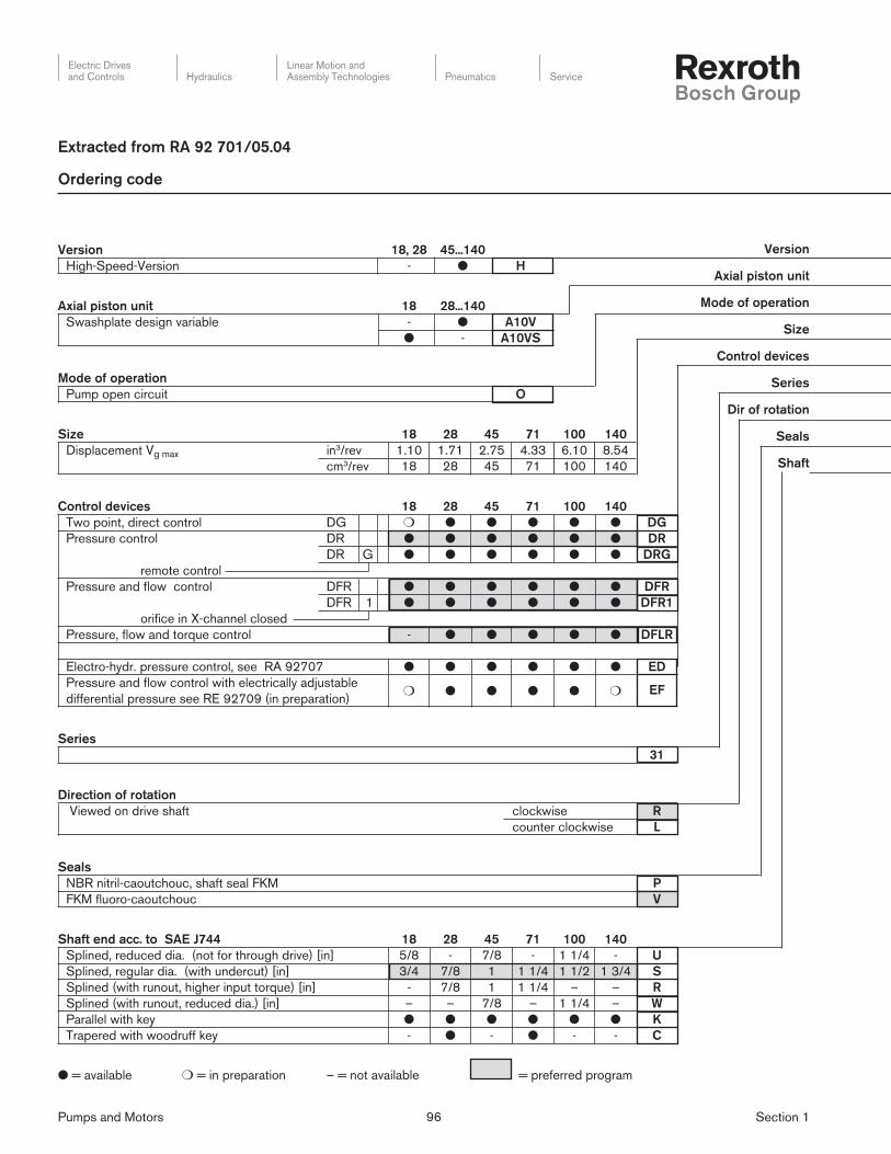
Pumps and Motors 96 Section 1
Electric Drivesand Controls Hydraulics
Linear Motion andAssembly Technologies Pneumatics Service
Version
Axial piston unit
Mode of operation
Size
Control devices
Series
Dir of rotation
Seals
Shaft
Extracted from RA 92 701/05.04
● = available ❍ = in preparation – = not available = preferred program
Version 18, 28 45...140
High-Speed-Version - ● H
Axial piston unit 18 28...140
Swashplate design variable - ● A10V
● - A10VS
Mode of operation
Pump open circuit O
Size 18 28 45 71 100 140
Displacement Vg max in3/rev 1.10 1.71 2.75 4.33 6.10 8.54
cm3/rev 18 28 45 71 100 140
Control devices 18 28 45 71 100 140
Two point, direct control DG ❍ ● ● ● ● ● DG
Pressure control DR ● ● ● ● ● ● DR
DR G ● ● ● ● ● ● DRG
remote control
Pressure and fl ow control DFR ● ● ● ● ● ● DFR
DFR 1 ● ● ● ● ● ● DFR1
orifi ce in X-channel closed
Pressure, fl ow and torque control - ● ● ● ● ● DFLR
d
Electro-hydr. pressure control, see RA 92707 ● ● ● ● ● ● ED
Pressure and fl ow control with electrically adjustable ❍ ● ● ● ● ❍ EF
differential pressure see RE 92709 (in preparation)
Series
31
Direction of rotation
Viewed on drive shaft clockwise R
counter clockwise L
Seals
NBR nitril-caoutchouc, shaft seal FKM P
FKM fl uoro-caoutchouc V
Shaft end acc. to SAE J744 18 28 45 71 100 140
Splined, reduced dia. (not for through drive) [in] 5/8 - 7/8 - 1 1/4 - U
Splined, regular dia. (with undercut) [in] 3/4 7/8 1 1 1/4 1 1/2 1 3/4 S
Splined (with runout, higher input torque) [in] - 7/8 1 1 1/4 – – R
Splined (with runout, reduced dia.) [in] – – 7/8 – 1 1/4 – W
Parallel with key ● ● ● ● ● ● K
Trapered with woodruff key - ● - ● - - C
Ordering code

Pumps and Motors 97 Section 1
Electric Drivesand Controls Hydraulics
Linear Motion andAssembly Technologies Pneumatics Service
Extracted from RA 92 701/05.04
A10V(S) O / 31 –
Port plate
91 and 61
without
through
drive only
Version
Axial piston unit
Mode of operation
Size
Control devices
Series
Direction of rotation
Seals
Shaft
Mounting fl ange acc. to SAE J744 18 28 45 71 100 140
2-hole ● ● ● ● ● - C
4-hole – – – – – ● D
Port for service lines 18 28 45 71 100 140
Pressure port B SAE fl ange rear, - - - ● - - 91
Suction port S fi xing thread UNC
Pressure port B SAE fl ange on opposite side - - - ● - - 92
Suction port S fi xing thread UNC
Pressure port B SAE fl ange rear, - ● ● - ● ● 61
Suction port S fi xing thread UNC
Pressure port B SAE fl ange on opposite side ● ● ● - ● ● 62
Suction port S fi xing thread UNC
Through drive 18 28 45 71 100 140
Without through drive ● ● ● ● ● ● N00
With through drive (port plate 62 org2)
Mounting fl ange1) Shaft/coupling2) Sealing
82-2 (A) 16-4 (A) axial ● ● ● ● ● ● K01
82-2 (A) 19-4 (A-B) axial ● ● ● ● ● ● K52
101-2 (B) 22-4 (B) axial – ● ● ● ● ● K68
101-2 (B) 25-4 (B-B) axial – – ● ● ● ● K04
127-2 (C) 32-4 (C) axial – – – ● ● ● K07
127-2 (C) 38-4 (C-C) axial – – – – ● ● K24
152-4 (D) 44-4 (D) axial – – – – – ● K17
1) Flange acc. to SAE J744
2) Coupling for splined shaft acc. to SAE J744 OCT83
For mounting options on through drive see page 29.

Pumps and Motors 98 Section 1
Electric Drivesand Controls Hydraulics
Linear Motion andAssembly Technologies Pneumatics Service
See Section 16 for applicable
Preferred/Spotlight part numbers
and unit price.
Size 18 28 45 71 100 140
High-Speed-Version 45 71 100 140
Displacement Vg max in3 1.10 1.71 2.75 4.33 6.10 8.54 2.75 4.33 6.10 8.54
(cm3) (18) (28) (45) (71) (100) (140) (45) (71) (100) (140)
Speed 1), max.
at Vg max no max rpm 3300 3000 2600 2200 2000 1800 3000 2550 2300 2050
at Vg < Vg max no max perm. rpm 3900 3600 3100 2600 2400 2100 3300 2800 2500 2200
Flow, max.
at no max qvo max gpm 15.6 22.2 30.9 41.2 52.8 66.6 35.7 47.8 60.7 75.8
(L/min) (59.4) (84) (117) (156) (200) (252) (135) (181) (230) (287)
at nE = 1800 rpm qvE gpm 8.5 13.2 21.4 33.8 47.5 66.6 21.4 33.8 47.5 66.6
(L/min) (32.4) (50) (81) (128) (180) (252) (81) (128) (180) (252)
Power (Δp = 4000 psi (280 bar) & Vg max)
at no max Po max HP 37 52 74 98 125 157 84 113 143 180
(kW) (27.7) (39) (55) (73) (93) (117) (63) (84) (107) (134)
at nE = 1800 rpm PE max HP 20 31 51 80 113 158 51 80 113 158
(kW) (15) (23) (38) (60) (84) (118) (38) (60) (84) (118)
Torque at Vg max
Δp = 4000 psi
(280 bar)
Tmax lb-ft 58.9 91 146 230 324 453 146 230 324 453
(Nm) (80.1) (125) (200) (316) (445) (623) (200) (316) (445) (623)
Δp = 1450 psi
(100 bar)
T lb-ft 21 33 53 83 117 164 53 83 117 164
(Nm) (28.6) (45) (72) (113) (159) (223) (72) (113) (159) (223)
Moment of inertia
about drive axis
J lb-ft2 0.022 0.040 0.078 0.197 0.396 0.574 0.078 0.197 0.396 0.574
(kgm2) (0.00093) (0.0017) (0.0033) (0.0083) (0.0167) (0.0242) (0.0033) (0.0083) (0.0167) (0.0242)
Max. angular acceleration rad/s 6800 5500 4000 2900 2400 2000 4000 2900 2400 2000
Torsional stiffness - shaft "S" lb-ft/rad 8149 16403 27562 52835 89039 124610 27562 52835 89039 124610
(Nm/rad) (11087) (22317) (37499) (71884) (121142) (169537) (37499) (71884) (121142) (169537)
shaft "U" lb-ft/rad 5946 22107 66953 22107 66953
(Nm/rad) (8090) (30077) (91093) (30077) (91093)
shaft "R" lb-ft/rad 19375 30153 56261 30153 56261
(Nm/rad) (26360) (41025) (76545) (41025) (76545)
shaft "W" lb-ft/rad 25330 74858 25330 74858
(Nm/rad) (34463) (101847) (34463) (101847)
shaft "K" lb-ft/rad 9805 19712 32270 60352 99448 144680 32270 60352 99448 144680
(Nm/rad) (13340) (26819) (43905) (82112) (135303) (196844) (43905) (82112) (135303) (196844)
Filling capacity gal. 0.1 0.18 0.26 0.42 0.58 0.79 0.26 0.42 0.58 0.79
(L) (0.4) (0.7) (1.0) (1.6) (2.2) (3.0) (1.0) (1.6) (2.2) (3.0)
Weight (without fl uid) m lbs 26 33 46 73 99 132 46 73 99 132
(kg) 12 15 21 33 45 60 21 33 45 601) Values shown are valid for an absolute pressure of 14.5 psi (1 bar) at inlet port S. At reduced displacement or increased
inlet pressure the speed may be increased according to the diagram.2) For higher radial loads, please consult us.
Table of values (theoretical values, without considering ηmh and ηv: values rounded)
Extracted from RA 92 701/05.04Page 4 of 4
Issue: 06.06
Technical Data

Pumps and Motors 99 Section 1
Electric Drivesand Controls Hydraulics
Linear Motion andAssembly Technologies Pneumatics Service
See Section 16 for applicable
Preferred/Spotlight part numbers
and unit price.
Extracted from RA 92 703/03.06Page 1 of 4
Issue: 06.06
Variable displacement pump
for open circuits,
Axial piston, swashplate design
Model A10VO
Size 10...85
Series 52/53
Nominal pressure 3600 psi (250 bar)
Peak pressure 4600 psi (315 bar)
– Variable axial piston pump in swashplate design for hydrostatic
drives in open circuits
– Flow is proportional to drive speed and displacement.The fl ow
is infi nitely variable by adjustment of the swashplate
– Strong bearings for long service life
– High permissible drive speeds
– High power-weight ratio - small dimensions
– Low noise level
– Good suction characteristics
– Axial and radial loading of drive shaft possible
– Pressure and fl ow control
– Electro-hydraulic pressure control
– Power control
– Electro-hydraulic displacement control
– Short response times
Series 52
Series 53
Electric Drivesand Controls Hydraulics
Linear Motion andAssembly Technologies Pneumatics Service

Pumps and Motors 100 Section 1
Electric Drivesand Controls Hydraulics
Linear Motion andAssembly Technologies Pneumatics Service
See Section 16 for applicable
Preferred/Spotlight part numbers
and unit price.
Ordering code
A10V(S) O / 5 – V
01 02 03 04 05 06 07 08 09 10 11 12
1) Size 60 only in series 52; size 63 only in series 53 (see also index 06 in ordering code)2) For availability of control options in series 52 and 53 (see also index 06 in ordering code)
Axial piston unit 10 28 45 60/631) 85
01Swash plate design, variable – – – – A10VS
– A10V
Operating mode
02 Pump, open circuit O
Size 10 28 45 60/631) 85
03Displacement Vg max [cm3] 10 28 45 63 85
[in3] 0.61 1.71 2.75 3.84 5.18
Control devices2)
04
Pressure control DR DR
with hydraulic fl ow control
X-T open DFR – DFR2)
X-T open DR F – DRF2)
X-T closed DFR1 DFR12)
X-T closed DR S – DRS2)
with fl ow control, electro-hydraulic adjustment of differential press.(inverse proportional characteristic) (RE 92 709)
EF . D . – EF.D.
with remote pressure control
hydraulic DR G DRG
electric, inverse charact. (RE 92 707) ED . – ED.
Power control
with pressure control
min. start of control
145 to 510 psi (10 to 35 bar) LA 5 D – LA5D
520 to 1015 psi (36 to 70 bar) LA 6 D – LA6D
1030 to 1520 psi (71 to 105 bar) LA 7 D – LA7D
1535 to 2030 psi (106 to 140 bar) LA 8 D – LA8D
2045 to 3335 psi (141 to 230 bar) LA 9 D – LA9D
with remote pressure control
min. start of control see above LA X D G – LAXDG
with pressure and fl ow control, X-T closed
min. start of control see above LA X D S – LAXDS
with press. and fl ow control, electro-hydr. adjustment of diff. press. (inverse prop. characteristic), X-T closed (RE 92 709)
min. start of control see above LA X S . – LAXS.
Electro-proportional displacement control (RE 92 708)
with pressure and fl ow control positive characteristic
EP . D . – EP.D.
with pressure and fl ow control positive characteristic; deactivation of control at I = 0
EK . D . – EK.D.
Extracted from RA 92 703/03.06Page 2 of 4
Issue: 06.06

Pumps and Motors 101 Section 1
Electric Drivesand Controls Hydraulics
Linear Motion andAssembly Technologies Pneumatics Service
See Section 16 for applicable
Preferred/Spotlight part numbers
and unit price.
A10V(S) O / 5 – V01 02 03 04 05 06 07 08 09 10 11 12
Series
05 5
Index 10 28 45 60 63 85
06
DR, DFR, DFR1, DRG, ED... – 21)
DR, DRF, DRS, DRG, ED... – – 3
EF..., LA..., EP..., EK... – – 3
Direction of rotation
07viewing on shaft end clockwise R
counter clockwise L
Seals
08 FKM fl uor-rubber V
Shaft end 10 28 45 60/63 85
09
Splined shaft to SAE J744, standard shaft S
Similar to shaft “S“ however for higher input torque – – R
Splined shaft to SAE J744, reduced diameter, not for through drive – U
similar to shaft “U“, higher input torque, not for through drive – – W
SAE key K2)
Tapered with Woodruff key – – C2)
Mounting fl ange
10SAE 2-hole C
SAE 4-hole – – – D
Port for service lines
11
SAE fl ange at rear, UNC threads (no through drive) – 61
SAE fl ange on side, opposite sides, UNC threads – 62
Threaded ports at rear, UN threads (no through drive) – – 642)
Through drive
12
Without through drive (only for port plate 61 and 64) N00
Flange SAE J744 Coupler for splined shaft3) Sealing
82-2 (A) 5/8 in 9T 16/32DP axial – K01
82-2 (A) 3/4 in 11T 16/32DP axial – K52
101-2 (B) 7/8 in 13T 16/32DP axial – K68
101-2 (B) 1 in 15T 16/32DP axial – – K04
127-4 (C) 1 1/4 in 14T 12/24DP axial – – – – K15
127-2 (C) 1 1/4 in 14T 12/24DP axial – – – – K07
127-2 (C) 1 1/2 in 17T 12/24DP axial – – – – K24
1) Not for new projects. For new projects use series 53 only.2) only series 523) 30° pressure angle, fl at base, fl ank centering, fi t class 5.
available in preparation – not available
Ordering code
Extracted from RA 92 703/03.06Page 3 of 4
Issue: 06.06

Pumps and Motors 102 Section 1
Electric Drivesand Controls Hydraulics
Linear Motion andAssembly Technologies Pneumatics Service
See Section 16 for applicable
Preferred/Spotlight part numbers
and unit price.
Size A10V(S)O 10 28 45 60 63 85
Displacement Vg max in3
(cm3)
0.61
(10.5)
1.71
(28)
2.75
(45)
3.66
(60)
3.84
(63)
5.18
(85)
Speed2)
max. at Vg max n0 max min-1 3600 3000 26003) 2700 2600 2500
max. at Vg ≤ Vg max n0 max zul min-1 4320 3600 3120 3240 3140 3000
Flow
at n0 max qV0 max gpm
(L/min)
9.7
(37)
22
(84)
31
(117)
43
(162)
43.1
(163)
55
(212)
at n0 max zul. qV0 max
zul.
gpm
(L/min)
11.4
(43,2)
26.6
(100)
37
(140)
51
(194)
52.2
(198)
67.3
(255)
Power Δp = 3600 psi (250 bar)
at n0 max Po max HP
(kW)
22
(16)
47
(35)
65
(49)
90
(68)
90
(68)
119
(89)
at n0 max zul. Po max
zul.
HP
(kW)
25.5
(18)
56
(42)
77.8
(58)
108
(81)
110
(82,5)
141
(106)
Torque
at Vg max Δp = 3600 psi
(250 bar)
Tmax lb-ft
(Nm)
31
(42)
82
(111)
131
(179)
175
(238)
184
(250)
247
(338)
Δp = 1440 psi
(100 bar)
T lb-ft
(Nm)
13
(16.7)
33
(44.5)
53
(71.5)
70
(95)
74
(100)
102
(135)
Moment of inertia
(about drive axis)
J lbs-ft2
(kgm2)
0.0142
(0.0006)
0.0403
(0.0017)
0.0783
(0.0033)
0.1329
(0.0056)
0.1329
(0.0056)
0.2848
(0.012)
Angular acceleration, max. rad/s2 8000 5500 4000 3300 3300 2700
Torsional stiffness Shaft S lb-ft/rad
(Nm/rad)
6760
(9200)
16400
(22300)
27560
(37500)
48100
(65500)
48100
(65500)
105100
(143000)
Shaft R lb-ft/rad
(Nm/rad)
—
—
19400
(26300)
30240
(41000)
51200
(69400)
51200
(69400)
—
—
Shaft U lb-ft/rad
(Nm/rad)
5020
(6800)
—
—
22130
(30000)
36290
(49200)
36290
(49200)
75900
(102900)
Shaft W lb-ft/rad
(Nm/rad)
—
—
—
—
25370
(34400)
39830
(54000)
39830
(54000)
86960
(117900)
Shaft P lb-ft/rad
(Nm/rad)
7890
(10700)
—
—
—
—
—
—
—
—
—
—
Case volume gal
(L)
0.05
(0.2)
0.08
(0.3)
0.13
(0.5)
0.21
(0.8)
0.21
(0.8)
0.26
(1)
Weight (without fl uid) lbs
(kg)
17
(8)
31
(14)
40
(18)
48.5
(22)
48.5
(22)
75
(34)
1) theoretical values, without considering ηmh and ηv, values rounded 2) Values are valid with inlet pressure of 1 bar at suction inlet S. With reduced displacement or increased inlet pressure the drive
speed can be increased according to the diagram on page 53) For higher drive speeds, please consult us.
Technical data
Extracted from RA 92 703/03.06Page 4 of 4
Issue: 06.06

Pumps and Motors 103 Section 1
Electric Drivesand Controls Hydraulics
Linear Motion andAssembly Technologies Pneumatics Service
See Section 16 for applicable
Preferred/Spotlight part numbers
and unit price.
Extracted from RA 92 711/05.95Page 1 of 4
Issue: 06.06
Variable displacement pump
for open circuits,
Axial piston, swashplate design
Model AA10VSO (A10VSO; Size 18)
Sizes 18 to 140, Series 31
Nominal pressure up to 280 bar (4000 PSI)
Maximum pressure up to 350 bar (5100 PSI)
– Variable displacement axial piston pump of swashplate design
for hydrostatic open circuit systems
– Flow is proportional to drive speed and displacement. It can be
infi nitely varied by adjustment of the swashplate.
– SAE mounting fl ange
– Flange connections to SAE
– Two case drain ports
– Good suction characteristics
– Permissible continous pressure 280 bar (4000 PSI)
– Low noise level
– Long service life
– Axial and radial load of drive shaft possible
– High power-weight ratio
– Wide range of controls
– Short response times
– Through drive option for multi-circuit system

Pumps and Motors 104 Section 1
Electric Drivesand Controls Hydraulics
Linear Motion andAssembly Technologies Pneumatics Service
See Section 16 for applicable
Preferred/Spotlight part numbers
and unit price.
Extracted from RA 92 711/05.95Page 2 of 4
Issue: 06.06
Ordering code
Hydraulic Fluid, Type of rotary group 18...45 71...140
Mineral oil and HFD (no code) l lHFA, HFB and HFC - Fluids l l E
High-Speed-Version — l H
Axial Piston Unit
Swashplate design, variable size 18 A10VS
size 28 to 140 AA10VS
Type of operation
Pump in open circuit ¢
Size 18 28 45 71 100 140
in3/rev. 1.10 1.71 2.75 4.33 6.10 8.54
cm3/rev. 18 28 45 71 100 140
Control device 18 28 45 71 100 140
Two-position control, direct controls DG l l l l l l DG
Pressure control DR l l l l l l DR
DR G l l l l l l DRG
remote control
Pressure flow control DFR l l l l l l DFR
DFR 1 l l l l l l DFR1
without orifice between X and tank
Pressure, flow and power control — l l l l l DFLR
Pressure and flow control, electronic, see RA30022 l l l l l l DFE1
Electro-hydraulic pressure control, see RE92707 l l l l l l ED
Series
31
Direction of rotation
Viewed on shaft end clockwise R
counter clockwise L
Seals
NBR nitril-caoutchouc, shaft seal in FKM P
FKM flour-caoutchouc V
Shaft end 18 28 45 71 100 140
SAE Parallel with key l l l l l l K
SAE Splined shaft l l l l l l S
SAE Splined shaft (higher through drive torque) l l l l — — R
SAE Splined shaft (not suitable for through drive) l — l — l — U
Mounting flange 18 28 45 71 100 140
SAE 2-bolt l l l l l — C
SAE 4-bolt — — — — — l D

Pumps and Motors 105 Section 1
Electric Drivesand Controls Hydraulics
Linear Motion andAssembly Technologies Pneumatics Service
See Section 16 for applicable
Preferred/Spotlight part numbers
and unit price.
Service line connections 18 28 45 71 100 140
Pressure port B and suction port S:
SAE ports at opposite sides l l l — l l 62
UNC fixing threads — — — l — — 92
Through drives 18 28 45 71 100 140
without through drive l l l l l l N00
with through drive to accept an axial piston pump or a gear pump
Mounting flange SAEJ744 hub sealing
82-2(A) keyed (A-B) axial ¢ l l l l l K401)
101-2 (B) keyed (B) axial — l l l l l K031)
101-2 (B-B) keyed (B-B) axial — — l l l l K051)
127-2 (C) keyed (C) axial — — — l l l K081)
127-2 (C) keyed (C) radial — — — — l l K381)
152-4 (D) keyed (D) axial — — — — — l K211)
82-2 (A) 5/8 in (A) axial l l l l l l K01
82-2 (A) 3/4 in (A-B) axial l l l l l l K52
101-2 (B) 7/8 in (B) axial — l l l l l K68
101-2 (B) 1 in (B-B) axial — — l l l l K04
127-2 (C) 1 1/4 in (C) axial — — — l l l K07
127-2 (C) 1 1/2 in (C-C) axial — — — — l l K24
152-4 (D) 1 3/4 in (D) axial — — — — — l K171) Not for new projects. Permitted with reduced throug drive torque only.
Hydraulic Fluid, Type of rotary group
Axial Piston Unit
Type of operation
Size
Control device
Series
Direction of rotation
Seals
Shaft end
Mounting flange
AA10VS O / 31 –
l = available
¢ = in preparation
– = not available
Extracted from RA 92 711/05.95Page 3 of 4
Issue: 06.06

Pumps and Motors 106 Section 1
Electric Drivesand Controls Hydraulics
Linear Motion andAssembly Technologies Pneumatics Service
See Section 16 for applicable
Preferred/Spotlight part numbers
and unit price.
Technical data
Extracted from RA 92 711/05.95Page 4 of 4
Issue: 06.06
± Fax
Fq
X
X/2 X/2
Application of force
Table of values (theoretical values, without considering ηmh and ηv: values rounded)
Size (A)A10VSO Standard 18 28 45 71 100 140
AA10VSO High Speed 71 100 140
Displacement Vg max cm3
(in3)
18
(1.10)
28
(1.71)
45
(2.75)
71
(4.33)
100
(6.10)
140
(8.54)
71
(4.33)
100
(6.10)
140
(8.54)
Speed1), max.
at Vg max n0 max rpm 3300 3000 2600 2200 2000 1800 2550 2300 2050
at increased inlet pressure
pabs resp. Vg < Vgmax
n0 max perm. rpm 3900 3600 3100 2600 2400 2100 2600 2400 2100
Flow, max
at n0 max qvo max L/min
(GPM)
59.4
(15.7)
84
(22)
117
(31)
156
(41)
200
(53)
252
(67)
181
(48)
230
(61)
287
(76)
at nE = 1800 rpm qvo L/min
(GPM)
32
(7.2)
59
(13.3)
81
(21.4)
128
(33.8)
180
(47.6)
252
(67)
128
(33.8)
180
(47.6)
252
(67)
Power, max. (Δp = 280 bar (4000 PSI)
at n0 max Po max kW
(HP)
28
(36.6)
39
(51)
55
(72)
73
(96)
93
(124)
118
(156)
84
(112)
107
(142)
134
(177)
at nE = 1800 rpm P kW
(HP)
15
(19)
24
(31)
38
(50)
69
(79)
84
(111)
118
(156)
69
(79)
84
(111)
118
(156)
Torque, max.
at Vg max
Δp= 280 bar (4000 PSI)
Tmax Nm
(ft-lb)
80
(58)
125
(91)
200
(146)
316
(230)
445
(324)
623
(453)
316
(230)
445
(324)
623
(453)
at Vg max
Δp= 100 bar (1450 PSI)
T Nm
(ft-lb )
28.6
(14.6)
45
(33)
72
(53)
113
(83)
159
(117)
223
(164)
113
(83)
159
(117)
223
(164)
Moment of inertia
(about drive axis)
J kgm2
(lbs-ft2)
0.0009
(0.022)
0.0017
(0.0403)
0.0033
(0.0783)
0.0083
(0.1970)
0.0167
(0.3963)
0.0242
(0.5743)
0.0083
(0.1970)
0.0167
(0.3963)
0.0242
(0.5743)
Fill volume L (gal.) 0.4 (0.1) 0.7 (0.2) 1.0 (0.3) 1.6 (0.4) 2.2 (0.6) 3.0 (0.8) 1.6 (0.4) 2.2 (0.6) 3.0 (0.8)
Weight (without fl uid) ca. m kg (lbs.) 12 (27) 15 (33) 21 (46) 33 (73) 45 (99) 60 (132) 33 (73) 45 (99) 60 (132)
Permissible loading of drive shaft
max. perm. load Fax max N
(lbs.)
700
(157)
1000
(225)
1500
(337)
2400
(540)
4000
(900)
4800
(1080)
2400
(540)
4000
(900)
4800
(1080)
max. perm. load2) Fq max N
(lbs.)
350
(79)
1200
(270)
1500
(337)
1900
(427)
2300
(517)
2800
(630)
1900
(427)
2300
(517)
2800
(630)
1) These values are valid for an absolute pressure of 14.5 psi (1 bar) at the suction port S.
By reducing the displacement or increasing the input pressure the speed can be
increased as shown in the diagram.
2) Please consult us for higher radial forces.

Pumps and Motors 107 Section 1
Electric Drivesand Controls Hydraulics
Linear Motion andAssembly Technologies Pneumatics Service
See Section 16 for applicable
Preferred/Spotlight part numbers
and unit price.
Extracted from RA 92 714/11.05Page 1 of 4
Issue: 06.06
Variable displacement pump
for open circuits,
Axial piston, swashplate design
Model A10VSO
Size 71...180
Series 32
Nominal pressure 4000 psi (280 bar)
Peak pressure 5100 psi (350 bar)
– Low noise level
– Variable pump in axial piston-swashplate design
– The fl ow is proportional to the drive speed and the displace-
ment
– Optimized housing and port plate structure to minimize noise
radiation
– Optional with pulsation damping
– High effi ciency
– Hydrostatic unloading of cradle bearings
– Double retainer mechanism for high speed version
(Size 140 and 180)
– Arrangement to counteract cylinder lift off
– Optimized sealing
– High functional reliability, also with torsional vibrations or under
unfavorable operating conditions
– Port for pressure transducer in pump outlet
– Universal through drive
– Excellent power to weight ratio

Pumps and Motors 108 Section 1
Electric Drivesand Controls Hydraulics
Linear Motion andAssembly Technologies Pneumatics Service
See Section 16 for applicable
Preferred/Spotlight part numbers
and unit price.
Extracted from RA 92 714/11.05Page 2 of 4
Issue: 06.06
Ordering code for standard program
Axial piston unit
01 Swashplate design, variable, industrial applications, nom. pres. 4000 psi (280 bar), peak press. 5100 psi (350 bar) A10VS
Type of operation
02 Pump, open circuit O
Size 45 71 100 140 180
03Displacement Vg max [cm3] 45 71,1 100 140 180
[in3] 2.75 4.34 6.10 8.54 10.98
Control and adjustment devices
04
Two-point control, directly operated DG DG
Pressure control DR DR
with fl ow control, hydraulic, X-T open DR F DRF
X-T closed DR S DRS
with displacement control, electronic DF E1 DFE11)
(with pressure control), remotely adjustable
hydraulic DR G DRG
electric, inversely prop. characteristic ED . ED.2)
Power control
with pressure control
Beginning of control
below
725 psi
(50 bar)LA 5 D LA5D
from 739.5 to 1305 psi
(51 to 90 bar)LA 6 D LA6D
1319.5 to 2320 psi
(91 to 160 bar)LA 7 D LA7D
2334.5 to 3480 psi
(160 to 240 bar)LA 8 D LA8D
over 3480 psi
(240 bar)LA 9 D LA9D
with pressure control, remotely adjustable
Beginning of control see above LA X D G LAXDG
with pressure and fl ow control, X-T closed
Beginning of control see above LA X D S LAXDS
with separate fl ow control, X-T closed
Beginning of control see above LA X S LAXS
A10VS O / 32 – V D S01 02 03 04 05 06 07 08 09 10 11 12

Pumps and Motors 109 Section 1
Electric Drivesand Controls Hydraulics
Linear Motion andAssembly Technologies Pneumatics Service
See Section 16 for applicable
Preferred/Spotlight part numbers
and unit price.
Extracted from RA 92 714/11.05Page 3 of 4
Issue: 06.06
Series
05 32
Direction of rotation
06viewing on shaft end clockwise R
counter clockwise L
Seals and fl uids 45 71 100 140 180
07FKM fl uor-rubber V
HFA, HFB and HFC-fl uids (except Skydrol) – C3)
Shaft end
08
keyed parallel shaft to SAE K
splined to SAE J744 S
like shaft end S , for higher torque inputs – – – R
Anbaufl ansch
09 SAE 4-hole D
Ports for service lines
10
outlet B and inlet S, SAE fl ange on side, opposite sides UNC thread for fi xing screws, without through drive 62N
like 62N however with universal through drive 72U
like 62N however with universal through drive and pulsation damping 82U
Through drive
11
without through drive (only for port plate 62N) 00
Flange SAE J744 Hub for splined shaft Sealing
82-2 (A) 5/8 in 9T 16/32DP axial 01
82-2 (A) 3/4 in 11T 16/32DP axial 52
101-2 (B) 7/8 in 13T 16/32DP axial 68
101-2 (B) 1 in 15T 16/32DP axial 04
127-4 (C) 1 1/4 in 14T 12/24DP axial – 15
152-4 (D) 1 1/2 in 17T 12/24DP axial – – 96
152-4 (D) 1 3/4 in 13T 8/16DP axial – – – 17
with shaft for through drive, without hub, without adapter fl ange, closed with cover (not for portplate 62N) 99
Type of rotary group
12 High speed (only with port plate 62N and 72U) – – – S
1) See RE 30 022, not for HFx-fl uids 2) See RE 92 707 3) See RE 90 223
available in preparation – not available
A10VS O / 32 – V D S01 02 03 04 05 06 07 08 09 10 11 12
Ordering code for standard program
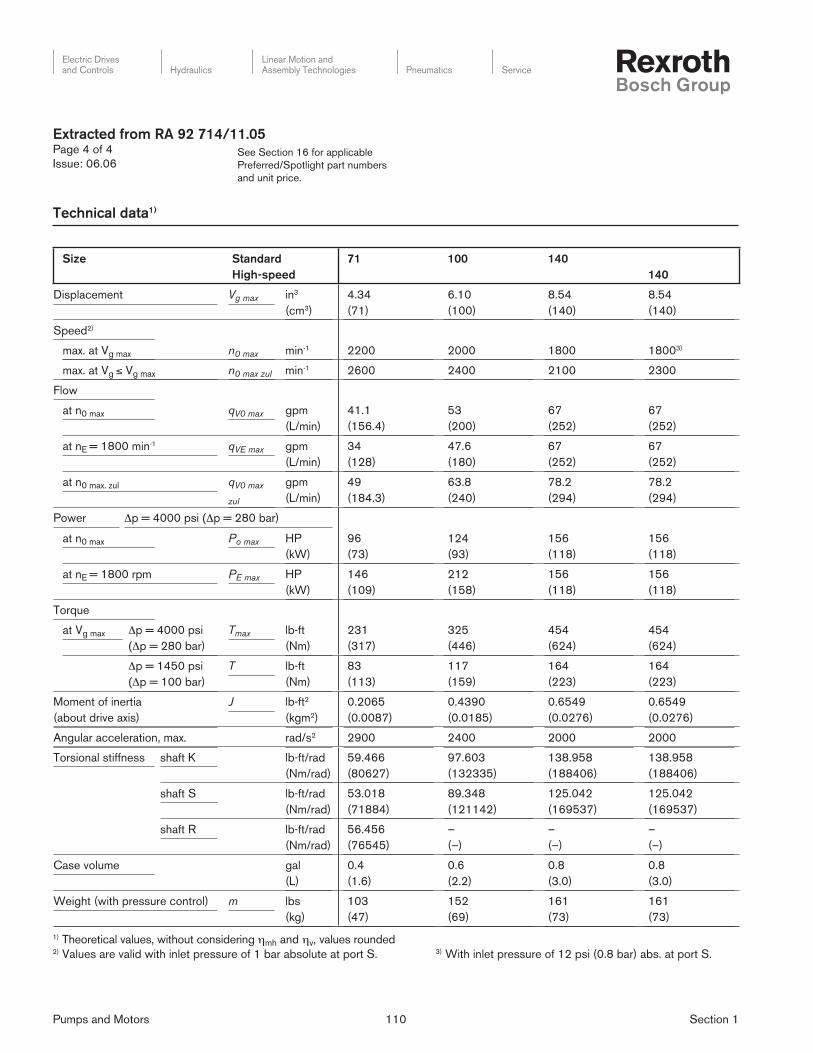
Pumps and Motors 110 Section 1
Electric Drivesand Controls Hydraulics
Linear Motion andAssembly Technologies Pneumatics Service
See Section 16 for applicable
Preferred/Spotlight part numbers
and unit price.
Technical data1)
Size Standard
High-speed
71 100 140
140
Displacement Vg max in3
(cm3)
4.34
(71)
6.10
(100)
8.54
(140)
8.54
(140)
Speed2)
max. at Vg max n0 max min-1 2200 2000 1800 18003)
max. at Vg ≤ Vg max n0 max zul min-1 2600 2400 2100 2300
Flow
at n0 max qV0 max gpm
(L/min)
41.1
(156.4)
53
(200)
67
(252)
67
(252)
at nE = 1800 min-1 qVE max gpm
(L/min)
34
(128)
47.6
(180)
67
(252)
67
(252)
at n0 max. zul qV0 max
zul
gpm
(L/min)
49
(184.3)
63.8
(240)
78.2
(294)
78.2
(294)
Power Δp = 4000 psi (Δp = 280 bar)
at n0 max Po max HP
(kW)
96
(73)
124
(93)
156
(118)
156
(118)
at nE = 1800 rpm PE max HP
(kW)
146
(109)
212
(158)
156
(118)
156
(118)
Torque
at Vg max Δp = 4000 psi
(Δp = 280 bar)
Tmax lb-ft
(Nm)
231
(317)
325
(446)
454
(624)
454
(624)
Δp = 1450 psi
(Δp = 100 bar)
T lb-ft
(Nm)
83
(113)
117
(159)
164
(223)
164
(223)
Moment of inertia
(about drive axis)
J lb-ft2
(kgm2)
0.2065
(0.0087)
0.4390
(0.0185)
0.6549
(0.0276)
0.6549
(0.0276)
Angular acceleration, max. rad/s2 2900 2400 2000 2000
Torsional stiffness shaft K lb-ft/rad
(Nm/rad)
59.466
(80627)
97.603
(132335)
138.958
(188406)
138.958
(188406)
shaft S lb-ft/rad
(Nm/rad)
53.018
(71884)
89.348
(121142)
125.042
(169537)
125.042
(169537)
shaft R lb-ft/rad
(Nm/rad)
56.456
(76545)
–
(–)
–
(–)
–
(–)
Case volume gal
(L)
0.4
(1.6)
0.6
(2.2)
0.8
(3.0)
0.8
(3.0)
Weight (with pressure control) m lbs
(kg)
103
(47)
152
(69)
161
(73)
161
(73)
1) Theoretical values, without considering ηmh and ηv, values rounded2) Values are valid with inlet pressure of 1 bar absolute at port S. 3) With inlet pressure of 12 psi (0.8 bar) abs. at port S.
Extracted from RA 92 714/11.05Page 4 of 4
Issue: 06.06

Pumps and Motors 111 Section 1
Electric Drivesand Controls Hydraulics
Linear Motion andAssembly Technologies Pneumatics Service
See Section 16 for applicable
Preferred/Spotlight part numbers
and unit price.
Extracted from RA 92 735/10.03Page 1 of 3
Issue: 06.06
Variable displacement pump
for open circuits,
Axial piston, swashplate design
Model A10VNO
Size 28...85
Series 52
Nominal pressure 3000 psi (210 bar)
Peak pressure 3600 psi (250 bar)
– Variable displacement axial piston pump in swashplate design
for hydrostatic drives in open circuits
– Flow is proportional to drive speed and displacement. It can be
infi nitely varied by adjustment of the swashplate
– High power to weight ratio - small dimensions
– Low noise level
– Permissible continuous pressure 3000 psi (210 bar)
– Axial and radial loading of drive shaft possible
– Pressure an fl ow control (load sensing)
– Short response times
– Well proven A10-Technology
– Extreme small mounting dimensions
– Cost effective alternative to fi xed displacement pumps
– Costs-optimized design
Electric Drivesand Controls Hydraulics
Linear Motion andAssembly Technologies Pneumatics Service
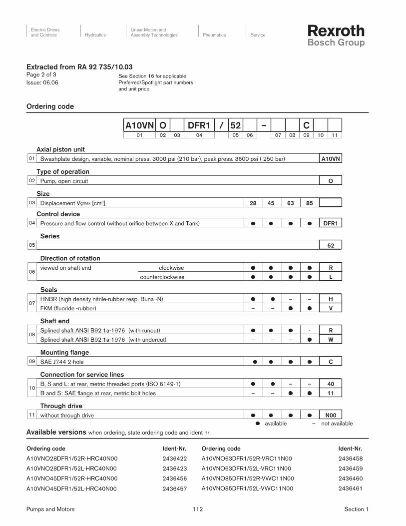
Pumps and Motors 112 Section 1
Electric Drivesand Controls Hydraulics
Linear Motion andAssembly Technologies Pneumatics Service
See Section 16 for applicable
Preferred/Spotlight part numbers
and unit price.
Axial piston unit
Swashplate design, variable, nominal press. 3000 psi (210 bar), peak press. 3600 psi ( 250 bar) A10VN
Type of operation
Pump, open circuit O
Size
Displacement Vgmax [cm3] 28 45 63 85
Control device
Pressure and fl ow control (without orifi ce between X and Tank) DFR1
Series
52
Direction of rotation
viewed on shaft end clockwise R
counterclockwise L
Seals
HNBR (high density nitrile-rubber resp. Buna -N) – – H
FKM (fl uoride -rubber) – – V
Shaft end
Splined shaft ANSI B92.1a-1976 (with runout) - R
Splined shaft ANSI B92.1a-1976 (with undercut) – – – W
Mounting fl ange
SAE J744 2-hole C
Connection for service lines
B, S and L: at rear, metric threaded ports (ISO 6149-1) – – 40
B and S: SAE fl ange at rear, metric bolt holes – – 11
Through drive
without through drive N00
Ordering code
Extracted from RA 92 735/10.03Page 2 of 3
Issue: 06.06
08
A10VN O DFR1 / 52 – C01 02 03 04 05 06 07 08 09 10 11
10
11
07
06
02
01
03
04
05
09
available – not available
Ordering code Ident-Nr.
A10VNO28DFR1/52R-HRC40N00 2436422
A10VNO28DFR1/52L-HRC40N00 2436423
A10VNO45DFR1/52R-HRC40N00 2436456
A10VNO45DFR1/52L-HRC40N00 2436457
Ordering code Ident-Nr.
A10VNO63DFR1/52R-VRC11N00 2436458
A10VNO63DFR1/52L-VRC11N00 2436459
A10VNO85DFR1/52R-VWC11N00 2436460
A10VNO85DFR1/52L-VWC11N00 2436461
Available versions when ordering, state ordering code and ident nr.

Pumps and Motors 113 Section 1
Electric Drivesand Controls Hydraulics
Linear Motion andAssembly Technologies Pneumatics Service
See Section 16 for applicable
Preferred/Spotlight part numbers
and unit price.
Technical data
± Fax
Fq
X
X/2 X/2
1,2
1,1
1,0
0,90,7 0,8 0,9
1,4 20
1,2 17.5
1,0 14.5
0,9 13
0,8 11.51,0
1,6 23
Inp
ut
pre
ssure
p
ab
s
Displacement Vg / Vgmax
bar psi
Sp
eed
n/n
max
Size 28 45 63 85
Displacement Vg max in3 (cm3) 1.71 (28) 2.74 (45) 3.84 (63) 5.18 (85)
Speed
max. at Vg max self priming (14.5 psi (1 bar)) n0 max rpm 3000 1800 1800 1800
with boost (72 psi (5 bar)) n0 max rpm 3500 2600 2600 2600
Flow
at n0 max self priming ((14.5 psi (1 bar)) qvo max gpm (L/min) 22.2 (84) 21.4 (81) 29.8 (113) 40.4 (153)
with boost (72 psi (5 bar)) qvo max gpm (L/min) 25.98 (98) 30.9 (117) 43 (163) 58.3 (221)
Power (Δp = 3000 psi (210 bar))
at n0 max self priming (14.5 psi (1 bar)) Po max HP (kW) 39 (29) 38 (28) 52 (39) 71 (53)
with boost (72 psi (5 bar)) Po max HP (kW) 45 (34) 55 (41) 76 (57) 104 (77)
Torque (Δp = 3000 psi (210 bar))
at Vg max Tmax ft-lb (Nm) 69 (94) 110 (150) 154 (210) 208 (284)
Moment of inertia (about drive axis) J lbs-ft2 (kgm2) 0.0403 (0.0017) 0.0474 (0.002) 0.0948 (0.004) 0.1422 (0.006)
angular acceleration, max. rad/s2 5500 4900 3500 2500
speed fl uctuation, max. rpm 70 65 57 47
Torsional stiffness Shaft end R lb-ft/rad (Nm/rad) 19480 (26500) 19480 (26500) 29770 (40500) 49900 (68000)
Shaft end W lb-ft/rad (Nm/rad) 14330 (19500) 14330 (19500) 25140 (34200) 39100 (53200)
Fill volume gal. (L) 0.08 (0.3) 0.08 (0.3) 0.13 (0.5) 0.21 (0.8)
Weight (without fl uid) m lbs (kg) 30.8 (14) 30.8 (14) 39.6 (18) 48.4 (22)
Permissible loading of drive shaft
max. prem. load Fax max lbf (N) 146 (650) 146 (650) 225 (1000) 300 (1350)
max. prem. load Fq max lbf (N) 146 (650) 146 (650) 225 (1000) 300 (1350)
Inlet operating pressure range
Absolute pressure at port S
pabs min _________________________________ 12 psi (0.8 bar)
pabs max ________________________________ 435 psi (30 bar)
Output operating pressure range
Pressure at port B
Nominal pressure pN ___________________ 3000 psi (210 bar)
Peak pressure pmax ____________________ 3600 psi (250 bar)
(Pressure data to DIN 24312)
Direction of fl ow
S to B.
Case drain pressure
The max. permissible pressure of the leakage fl uid (at port L, L1)
max. 7 psi (0,5 bar) higher than inlet pressure at port S, but not
higher than 29 psi (2 bar) absolute.
pL abs max __________________________________29 psi (2 bar)
Maximum permissible speed (Speed limit)
Graph, showing permissible speed with increased inlet pressure
at port S ( pabs ) resp. reduced displacement(Vg < Vg max ).
Extracted from RA 92 735/10.03Page 3 of 3
Issue: 06.06
Table of values

Pumps and Motors 114 Section 1
Electric Drivesand Controls Hydraulics
Linear Motion andAssembly Technologies Pneumatics Service
See Section 16 for applicable
Preferred/Spotlight part numbers
and unit price.
Extracted from RA 92 750/06.06Page 1 of 4
Issue: 06.06
Variable displacement pump
for closed circuits,
Axial piston, swashplate design
Model AA10VG
Sizes 18...63
Series 1
Nominal pressure 4350 psi (300 bar)
Peak pressure 5100 psi (350 bar)
– Variable displacement axial piston pump with swashplate de-
sign for hydrostatic closed circuit transmissions
– Flow is proportional to drive speed and displacement and is
infi nitely variable
– Output fl ow increases with the swivel angle of the swash plate
from 0 to its maximum value
– Flow direction changes smoothly when the swashplate is
moved through the neutral position
– A wide range of highly adaptable control instruments is avail-
able for different control and regulating functions
– The pump is equipped with two pressure relief valves on the
high pressure ports to protect the hydrostatic transmission
(pump and motor) from overload
– The pressure relief valves also function as boost inlet valves
– An integral auxiliary pump serves as boost and pilot oil pump
– The maximum boost pressure is limited by a built-in boost pres-
sure relief valve
Changes in ordering code from 06.04 issue
– Control device
- new standard: supply fi ltration at HD3, EP3 and EP4 control
- not for new projects: HD1, EP1, EP2
– Range of male connectors for solenoids
- not for new projects: H

Pumps and Motors 115 Section 1
Electric Drivesand Controls Hydraulics
Linear Motion andAssembly Technologies Pneumatics Service
See Section 16 for applicable
Preferred/Spotlight part numbers
and unit price.
Axial piston unit
01 Variable swashplate design, nominal pressure 4350 psi (300 bar), peak pressure 5100 psi (350 bar) AA10V
Operation
02 Pump in closed circuit G
Size
03≈ Displacement Vg max cm3 18 28 45 63
in3 1.10 1.71 2.81 3.84
Control device 18 28 45 63
04
Hydraulic control pilot pressure related without supply fi ltration ▲ ▲ ▲ ▲ HD1
with supply fi ltration ● ● ● ● HD3
mechanical servo ● ● ● ● HW
direct operated ● ● ● ● DG
speed related U = 12 V DC – ● ● ● DA1
U = 24 V DC – ● ● ● DA2
Electrical control with proportional solenoid without supply fi ltration U = 12 V DC ▲ ▲ ▲ ▲ EP1
U = 24 V DC ▲ ▲ ▲ ▲ EP2
with supply fi ltration U = 12 V DC ● ● ● ● EP3
U = 24 V DC ● ● ● ● EP4
with switching solenoid U = 12 V DC ● ● ● ● EZ1
U = 24 V DC ● ● ● ● EZ2
Mechanical pivot control ● – – – MD
Pressure cut-off 18 28 45 63
05Without pressure cut-off (no code) ● ● ● ●
With pressure cut-off (standard for version with DA control valve) – ● ● ● D
Neutral position switch (only for HW) 18 28 45 63
06Without neutral position switch (no code) ● ● ● ●
With neutral position switch ● ● ● ● L
Mechanical stroke limiter 18 28 45 63
07Without mechanical stroke limiter (no code) ● ● ● ●
With mechanical stroke limiter, external adjustable ● ● ● ● M
Spring neutral position centering (only MD) 18 28 45 63
08Without spring neutral position centering (no code) ● – – –
With spring neutral position centering ● – – – N
DA control valve HD HW DG DA EP EZ 28 45 63
09
Without DA control valve ● ● ● – ● ● ● ● ● 1
With DA control valve, fi xed setting ● ● ● ● ● – ● ● ● 2
With DA control valve, mech. adjust. with control lever
operating direction counter-clockwise ● ● ● ● ● – ● ● ● 3L
clockwise ● ● ● ● ● – ● ● ● 3R
With DA control valve, fi xed setting and hydraulic inch valve built-on, control with brake fl uid
– – – ● – – ● ● ● 4
With DA control valve, fi xed setting, connections for master controller
● ● ● ● ● – ● ● ● 7
With DA control valve, fi xed setting and hydraulic inch valve built-on, control with mineral oil
– – – ● – – ● ● ● 8
AA10V G / 10 – N C01 02 03 04 05 06 07 08 09 10 11 12 13 14 15 16 17 18 19 20
Ordering Code
Extracted from RA 92 750/06.06Page 2 of 4
Issue: 06.06

Pumps and Motors 116 Section 1
Electric Drivesand Controls Hydraulics
Linear Motion andAssembly Technologies Pneumatics Service
See Section 16 for applicable
Preferred/Spotlight part numbers
and unit price.
Series
10 Series 1, Index 0 10
Direction of rotation 18...63
11Viewed from shaft end clockwise ● R
counter-clockwise ● L
Seals
12 NBR (nitril-caoutchouc), shaft seal in FKM (fl uor-caoutchouc) N
Shaft end (permissible input torque see page X) 18 28 45 63
13Splined shaftANSI B92.1a-1976
standard for single pump ● ● ● ● S
standard for combination pump – – ● ● T
Mounting fl ange
14 SAE J744 – 2-hole C
Service line ports (metric thread) 18 28 45 63
15SAE fl ange ports A and B, same side left, suction port S bottom – ● ● ● 60
Threaded ports A and B, same side right, suction port S bottom ● – – – 66
Boost pump 18 28 45 63
16
Without integral boost pump without through drive ● ● ● ● N00
with through drive ● ● ● ● K..
With integral boost pump without through drive ● ● ● ● F00
with through drive ● ● ● ● F..
Through drive
17
Flange SAE J744 1) Splined shaft hub 18 28 45 63
82-2 (A) 5/8 in 9T 16/32DP 2) ● ● ● ● .01
101-2 (B) 7/8 in 13T 16/32DP 2) ● ● ● ● .02
1 in 15T 16/32DP 2) – ● ● ● .04
127-2 (C) 1 1/4 in 14T 12/24DP 2) – – – ● .07
Valves Setting range 18 28 45 63
18
With high pressure relief valve,direct controlled, (fi xed setting)
3600...4600 psi without bypass ● ● ● ● 3
(250...320 bar) with bypass ● ● ● ● 5
1450...3600 psi without bypass ● ● ● ● 4
(100...250 bar) with bypass ● ● ● ● 6
Filtration 18 28 45 63
19
Filtration in the suction line of the boost pump ● ● ● ● S
Filtration in the pressure line of the boost pumpports for external boost circuit fi lter, (Fe and G (Fa))
– ● 3) ● 3) ● D
External supply (model without integral boost pump - N00, K...) ● ● ● ● E
Range of male connectors for solenoids (only for EP, EZ and DA) 18 28 45 63
20
DEUTSCH male connector2-pin
without quenching diode ● ● ● ● P
with quenching diode (only for EZ and DA) ❍ ❍ ❍ ❍ Q
DIN male connector to HIRSCHMANN without quenching diode ▲ ▲ ▲ ▲ H1) 2 = 2-hole2) splined shaft hub to ANSI B92.1a-1976 (splined shaft allocation to SAE J744, see pages XX)3) pressure fi ltration in connection with the DA control valve is not possible.
= available ❍ = available on request ▲ = not for new projects – = not available
AA10V G / 10 – N C01 02 03 04 05 06 07 08 09 10 11 12 13 14 15 16 17 18 19 20
Ordering Code
Extracted from RA 92 750/06.06Page 3 of 4
Issue: 06.06
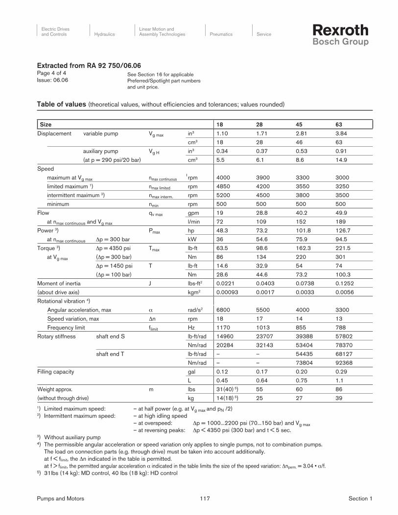
Pumps and Motors 117 Section 1
Electric Drivesand Controls Hydraulics
Linear Motion andAssembly Technologies Pneumatics Service
See Section 16 for applicable
Preferred/Spotlight part numbers
and unit price.
Extracted from RA 92 750/06.06Page 4 of 4
Issue: 06.06
Size 18 28 45 63
Displacement variable pump Vg max in3 1.10 1.71 2.81 3.84
cm3 18 28 46 63
auxiliary pump Vg H in3 0.34 0.37 0.53 0.91
(at p = 290 psi/20 bar) cm3 5.5 6.1 8.6 14.9
Speed
maximum at Vg max nmax continuous rpm 4000 3900 3300 3000
limited maximum 1) nmax limited rpm 4850 4200 3550 3250
intermittent maximum 2) nmax interm. rpm 5200 4500 3800 3500
minimum nmin rpm 500 500 500 500
Flow qv max gpm 19 28.8 40.2 49.9
at nmax continuous and Vg max l/min 72 109 152 189
Power 3) Pmax hp 48.3 73.2 101.8 126.7
at nmax continuous Δp = 300 bar kW 36 54.6 75.9 94.5
Torque 3) Δp = 4350 psi Tmax lb-ft 63.5 98.6 162.3 221.5
at Vg max (Δp = 300 bar) Nm 86 134 220 301
Δp = 1450 psi T lb-ft 14.6 32.9 54 74
(Δp = 100 bar) Nm 28.6 44.6 73.2 100.3
Moment of inertia J lbs-ft2 0.0221 0.0403 0.0738 0.1252
(about drive axis) kgm2 0.00093 0.0017 0.0033 0.0056
Rotational vibration 4)
Angular acceleration, max α rad/s2 6800 5500 4000 3300
Speed variation, max Δn rpm 18 17 14 13
Frequency limit flimit Hz 1170 1013 855 788
Rotary stiffness shaft end S lb-ft/rad 14960 23707 39388 57802
Nm/rad 20284 32143 53404 78370
shaft end T lb-ft/rad – – 54435 68127
Nm/rad – – 73804 92368
Filling capacity gal 0.12 0.17 0.20 0.29
L 0.45 0.64 0.75 1.1
Weight approx. m lbs 31(40) 5) 55 60 86
(without through drive) kg 14(18) 5) 25 27 39
1) Limited maximum speed: – at half power (e.g. at Vg max and pN /2)2) Intermittent maximum speed: – at high idling speed
– at overspeed: Δp = 1000...2200 psi (70...150 bar) and Vg max
– at reversing peaks: Δp < 4350 psi (300 bar) and t < 5 sec.3) Without auxiliary pump4) The permissible angular acceleration or speed variation only applies to single pumps, not to combination pumps.
The load on connection parts (e.g. through drive) must be taken into account additionally.
at f < flimit, the Δn indicated in the table is permitted.
at f > flimit, the permitted angular acceleration α indicated in the table limits the size of the speed variation: Δnperm. = 3.04 • α/f.5) 31lbs (14 kg): MD control, 40 lbs (18 kg): HD control
Table of values (theoretical values, without effi ciencies and tolerances; values rounded)

Pumps and Motors 118 Section 1
Electric Drivesand Controls Hydraulics
Linear Motion andAssembly Technologies Pneumatics Service
See Section 16 for applicable
Preferred/Spotlight part numbers
and unit price.
Extracted from RA 30 024/10.02Page 1 of 3
Issue 06.06
Closed loop pressure and
flow control system
Model SYDFE1
Series 2X
– The DFE1 control is used for the electro-hydraulic closed loop
control of the pressure and swivel angle of a variable dis place -
ment axial piston pump
The SYDFE1 closed loop control system is comprised of the
following components:
– AA10VSO axial piston pump with built-on VT-DFP-2X pro por -
tion al valve, which serves as the pilot valve, and inductive posi-
tion trans duc ers for sensing the swivel angle and valve position
– VT 5041-2X analog amplifi er for the realization of all of the
electrical functions required for the DFE1 control
– Pump pre-load valve (optional)
– Combination pumps are possible
Model SYDFE1-2X/071R-PSA12N00-0000-A030PX2

Pumps and Motors 119 Section 1
Electric Drivesand Controls Hydraulics
Linear Motion andAssembly Technologies Pneumatics Service
See Section 16 for applicable
Preferred/Spotlight part numbers
and unit price.
Extracted from RA 30 024/10.02Page 2 of 3
Issue: 06.06
Ordering code
Single pump 1)
Pump
combination 2)
Series 20 to 29 = 2X
(20 to 29: unchanged
installation and connection
dimensions)
A10VSO pump
Size 18 = 018
Size 28 = 028
Size 45 = 045
Size 71 = 071
Size 100 = 100
Size 140 = 140
Direction of rotation
Clockwise (preferred types
for through-drive pumps) = R
Anti-clockwise = L
Hydraulic fluid
Mineral oil to DIN 51 524 (HL / HLP) = P
Shaft end
( = Preferred types for through-drive pumps)
Size 18 28 45 71 100 140
3) – Ø22 Ø25 Ø32 Ø40 Ø45 = P
4) 3/4” – – – 1 1/2” 1 3/4” = S
5) – 7/8” 1” 1 1/4” – – = R
Connection flange ( l = available)
Size 18 28 45 71 100 140
ISO 2-hole – l l l l – = A
ISO 4-hole – – – – – l = B
SAE 2-hole l – – – – – = C
Connection for service lines Pressure port B SAE on opposite sides = 12
Pressure port S Mounting thread, metric
Through-drive (see table on page 3)
Without through-drive
Through-drive without hub for mounting:
(any built-on pumps with SAE splined shaft profile )
= N00
Center diameter Built-on pump
Ø82.55 mm (3.25 in.) A10VSO18 = KC1 6)
Ø100 mm (3.94 in.) A10VSO28/45 = KD3 6)
Ø125 mm (4.92 in.) A10VSO71/100 = KD5 6)
Ø180 mm (7.09 in.) A10VSO140 = KD7 6)
Ø101.6 mm (4.00 in.) Gear pump = KC3 6)
Ø127 mm (5.00 in.) Gear pump = KC5 6)
For single pumps, the hub must be ordered separately, if required
For double pumps, the hub is included in the scope of supply.
Further details in clear text
Preload valve
1 = Pressure limitation 200 bar (2900 PSI)
2 = Pressure limitation250 bar (3626 PSI)
3 = Pressure limitation300 bar (4350 PSI)
X = Without preload valve
Pressure transducer
HM 12 (4 to 20 mA) C = Measuring range
315 bar (4568 PSI)HM 13 (0 to 10 V)
G = Measuring range 315 bar (4568 PSI)
X = Without pressure transducer
Electronic assembly, VT 5041-2X with switch-able
actual pressure value signal (from series 25)
P = 4-20 mA / 0-10 V / 0-5 V / 1-10 V X = Without amplifier
Additional function, VT 5041-2X with
power limiter and swivel angle indicator
X = Without amplifier
1 = Amplifier without additional function
3 = Amplifier with additional function
Valve, installation orientation
0 = Plug-in connector installed radially to pump axis
A = Valve, spool variant
Basic pump version
0000 = Standard (internal pilot oil supply)0479 = External supply (sizes 18 … 100) 0487 = External supply (size 140)
1) See order example at the top of page 3 2) See order example at the top of page 33) Cylindrical with keyed shaft DIN 68854) Splined shaft profi le SAE5) Splined shaft profi le SAE (higher trough-drive torque)6) Through-drive is fi tted with an operationally safe
blind cover
SYDFE1 – 2X / – P 12 – – A 0 0 *

Pumps and Motors 120 Section 1
Electric Drivesand Controls Hydraulics
Linear Motion andAssembly Technologies Pneumatics Service
See Section 16 for applicable
Preferred/Spotlight part numbers
and unit price.
Extracted from RA 30 024/10.02Page 3 of 3
Issue: 06.06
Ordering code
1) Order example of single pump
SYDFE1-2X/100R-PSA12N00-0479-A0X0XCX
2) Order example of pump combination
Both model designations must be connected with “+“ (material number of 1st pump + material number of 2nd pump)
SY2DFE1-2X/100-100/ R900709794 + R900709794
SY2DFE1-2X/100-100/ SYDFE1-2X/100R-PSA12KD5-0000-A010PCX + SYDFE1-2X/100R-PSA12KD5-0000-A010PCX
Double pump
Size of front pump
Size of rear pump
Material number of front pump(or details in clear text, if material number is not known)
Material number of rear pump(or details in clear text, if material number is not known)
Order example
Single pumps
Model Material no.
SYDFE1-2X/018R-PSC12N00-0000-A010PCX R900783410
SYDFE1-2X/028R-PPA12N00-0000-A010PCX R900708517
SYDFE1-2X/045R-PPA12N00-0000-A010PCX R900708518
SYDFE1-2X/071R-PPA12N00-0000-A010PCX R900708519
SYDFE1-2X/100R-PPA12N00-0000-A010PCX R900708520
SYDFE1-2X/140R-PPB12N00-0000-A010PCX R900708521
Through-drive pumps for pump combinations
Model Material no.
SYDFE1-2X/028R-PRA12KD3-0000-A010PCX R900709782
SYDFE1-2X/045R-PRA12KD3-0000-A010PCX R900709786
SYDFE1-2X/071R-PRA12KD5-0000-A010PCX R900709792
SYDFE1-2X/100R-PSA12KD5-0000-A010PCX R900709794
SYDFE1-2X/140R-PSB12KD7-0000-A010PCX R900709795
Size
Through-drive ( = available) 18 28 45 71 100 140
Without through-drive N00
With through-drive for building on an axial piston unit, a gear pump or a radial piston pump
Mounting fl ange Shaft/coupling (separate order) for mounting:
ISO 100, 2-hole Splined shaft 7/8“ 22-4 (SAE B) A10VSO 28 (shaft S or R) – KD3
ISO 100, 2-hole Splined shaft1“ 25-4 (SAE B-B) A10VSO 45 (shaft S or R) – – KD3
ISO 125, 2-hole Splined shaft 1 1/4“ 32-4 (SAE C) A10VSO 71 (shaft S or R) – – – KD5
ISO 125, 2-hole Splined shaft 1 1/2“ 38-4 (SAE C-C) A10VSO 100 (shaft S) – – – – KD5
ISO 180, 4-hole Splined shaft 1 3/4“ 44-4 (SAE D) A10VSO 140 (shaft S) – – – – – KD7
82-2 (SAE A, 2-hole) Splined shaft 5/8“ 16-4 (SAE A) 1PF2G2, PGF2 KC1
82-2 (SAE A, 2-hole) Splined shaft 3/4“ 19-4 (SAE A-B) A10VSO 10, 18 (shaft S) KC1
101-2 (SAE B) Splined shaft 7/8“ 22-4 (SAE B) A10VO 28 (shaft S), PGF3 – KC3
101-2 (SAE B) Splined shaft 1“ 25-4 (SAE B-B) A10VO 45 (shaft S), PGH4 – KC3
127-2 (SAE C) Splined shaft 1 1/4“ 32-4 (SAE C) A10VO 71 (shaft S) – – – KC5
127-2 (SAE C) Splined shaft 1 1/2“ 38-4 (SAE C-C) A10VO 100 (shaft S), PGH5 – – – – KC5
152-4 (SAE D) Splined shaft 1 3/4“ 44-4 (SAE D) A10VO 140 (shaft S) – – – – – KC6
Standard models

Pumps and Motors 121 Section 1
Electric Drivesand Controls Hydraulics
Linear Motion andAssembly Technologies Pneumatics Service
See Section 16 for applicable
Preferred/Spotlight part numbers
and unit price.
Extracted from RA 30 030/10.02Page 1 of 3
Issue: 06.06
Pressure and fl ow closed loop system
Model SYDFEE
Series 2X
The DFEE control is used for the electro-hydraulic closed loop
control of the pressure and swivel angle of an axial piston pump
The SYDFEE.. closed loop control system consists of the fol-
low ing com po nents:
– AA10VSO axial piston pump with built-on proportional valve as
the pilot valve VT-DFPE…-2X/..
– The VT-DFPE..-2X/.. valve with integrated analog con trol and
closed loop control electronics realizes the complete closed
loop control function for the DFEE system
– The acquisition of the swivel angle is via a rotary angle sen sor
type VT-SWA-1-1X which is a hall effect based sensor
– Pump pre-load valve (optional)
– Combination pumps are possible
Model SYDFEE-2X/071R-PSA12N00-0000-A2AOFL2

Pumps and Motors 122 Section 1
Electric Drivesand Controls Hydraulics
Linear Motion andAssembly Technologies Pneumatics Service
See Section 16 for applicable
Preferred/Spotlight part numbers
and unit price.
Extracted from RA 30 030/10.02Page 2 of 3
Issue: 06.06
Ordering code
Single pump 1)
Pump combination 2)
Series 20 to 29 = 2X
(20 to 29: unchanged instal-lation and connection dimen-sions)
Pump A10VSO
Nominal Size 18 = 018
Nominal Size 28 = 028
Nominal Size 45 = 045
Nominal Size 71 = 071
Nominal Size 100 = 100
Nominal Size 140 = 140
Direction of rotationClockwise (pref. types for through drive pumps) = R
Anti-clockwise = L
Pressure fluidMineral oil to DIN 51 524 (HL/HLP) = P
Shaft end( = Preferred types for through drive pumps)
NS 18 28 45 71 100 140
3) – Ø22 Ø25 Ø32 Ø40 Ø45 = P
4) 3/4” – – – 1 1/2” 1 3/4” = S
5) – 7/8” 1” 1 1/4” – – = R
Connection flange (l = available)
NS 18 28 45 71 100 140
ISO 2-hole – l l l l – = A
ISO 4-hole – – – – – l = B
SAE 2-hole l – – – – – = C
Actuator line connectionsPressure connection B SAE, on opposite sides = 12
Suction connection S metric mounting heads
Through drive (see table on page 3)Without through drive Through drive without hub for mounting: (All built-on pumps are with a SAE splined shaft)
= N00
Centre dia. Pump to be fitted
Ø82.55 mm (3.25 in.) A10VSO18 = KC1 6)
Ø100 mm (3.94 in.) A10VSO28/45 = KD3 6)
Ø125 mm (4.92 in.) A10VSO71/100 = KD5 6)
Ø180 mm (7.09 in.) A10VSO140 = KD7 6)
Ø101.6 mm (4.00 in.) Gear pump = KC3 6)
Ø127 mm (5.00 in.) Gear pump = KC5 6)
With single pumps the hub must be ordered separately.With combination pumps the hub is included within the scope of supply.
SYDFEE – 2X / – P 12 – – A *
Further details in clear text
Pre-load valve 1 = Pressure limitation
200 bar (2900 PSI) 2 = Pressure limitation 250 bar (3636 PSI) 3 = Pressure limitation 300 bar (4351 PSI) X = Without pre-load valve
Pressure transducerC = HM 12 (4 to 20 mA)
measuring range up to 315 bar (4568 PSI)
G = HM 13 (0 to 10 V)measuring range up to
315 bar (4568 PSI)L = HM 16 (0.5 to 5 V)
measuring range up to 315 bar (4568 PSI) 7)
with connection cable 0.5 m (1.64 ft.)
and plug-in connector M12X = Without pressure transducer
Actual pressure inputC = Current input 4 – 20 mAV = Voltage input 0 – 10 VD = Voltage input 0 – 5 VE = Voltage input 1 – 10 VF = Voltage input 0.5 – 5 V 8)
Electronic sub-assembly, optional0 = No option1 = Without leakage oil compensation
Additional function “power limitation”A = Without power limitationB = With power limitation
Valve, mounting orientation, integrated electronics0 = Radial to the pump axis2 = 90° in the direction of the connection plate
A = Valve, spool version
Basic pump version0000 = Remote supply (NS 18 … 100)0487 = Remote supply (NS 140)
1) See ordering example at the top of page 32) See ordering example at the top of page 33) Cylinderical with key, DIN 68854) SAE spline profi le5) SAE spline profi le (higher through drive torque)6) The through drive is covered by a cover plate7) For direct connection to the integrated electronics version
“actual pressure input F”8) Connection via component socket M12

Pumps and Motors 123 Section 1
Electric Drivesand Controls Hydraulics
Linear Motion andAssembly Technologies Pneumatics Service
See Section 16 for applicable
Preferred/Spotlight part numbers
and unit price.
Extracted from RA 30 030/10.05Page 3 of 3
Issue: 06.06
Ordering code
Nominal size
Through drive ( l = available) 18 28 45 71 100 140
Without through drive l l l l l l N00
With through drive for mounting an axial piston pump, a gear pump or radial piston pump
Mounting fl ange Shaft/coupling (separate order) For fi tting a:
ISO 100, 2-hole Splined shaft 7/8” 22-4 (SAE B) A10VSO 28 (shaft S or R) – l l l l l KD3
ISO 100, 2-hole Splined shaft 1” 25-4 (SAE B-B) A10VSO 45 (shaft S or R) – – l l l l KD3
ISO 125, 2-hole Splined shaft 1 1/4” 32-4 (SAE C) A10VSO 71 (shaft S or R) – – – l l l KD5
ISO 125, 2-hole Splined shaft 1 1/2” 38-4 (SAE C-C) A10VSO 100 (shaft S) – – – – l l KD5
ISO 180, 4-hole Splined shaft 1 3/4” 44-4 (SAE D) A10VSO 140 (shaft S) – – – – – l KD7
82-2 (SAE A, 2-hole) Splined shaft 5/8” 16-4 (SAE A) 1PF2G2, PGF2 l l l l l l KC1
82-2 (SAE A, 2-hole) Splined shaft 3/4” 19-4 (SAE A-B) A10VSO 10, 18 (shaft S) l l l l l l KC1
101-2 (SAE B) Splined shaft 3/8” 22-4 (SAE B) A10VO 28 (shaft S), PGF3 – l l l l l KC3
101-2 (SAE B) Splined shaft 1” 25-4 (SAE B-B) A10VO 45 (shaft S), PGH4 – l l l l l KC3
127-2 (SAE C) Splined shaft 1 1/4” 32-4 (SAE C) A10VO 71 (shaft S) – – – l l l KC5
127-2 (SAE C) Splined shaft 1 1/2” 38-4 (SAE C-C) A10VO 100 (shaft S), PGH5 – – – – l l KC5
152-4 (SAE D) Splined shaft 1 3/4” 44-4 (SAE D) A10VO 140 (shaft S) – – – – – l KC6
Single pump
Model Material No.
SYDFEE-2X/018R-PSC12N00-0000-A0A0CCX R900708503
SYDFEE-2X/018R-PSC12N00-0000-A0A0CC2 R900708504
SYDFEE-2X/028R-PPA12N00-0000-A0A0CCX R900708505
SYDFEE-2X/028R-PPA12N00-0000-A0A0CC2 R900708506
SYDFEE-2X/045R-PPA12N00-0000-A0A0CCX R900708507
SYDFEE-2X/045R-PPA12N00-0000-A0A0CC2 R900708508
SYDFEE-2X/071R-PPA12N00-0000-A0A0CCX R900708510
SYDFEE-2X/071R-PPA12N00-0000-A0A0CC2 R900708511
SYDFEE-2X/100R-PPA12N00-0000-A0A0CCX R900708512
SYDFEE-2X/100R-PPA12N00-0000-A0A0CC2 R900708513
SYDFEE-2X/140R-PPB12N00-0000-A0A0CCX R900708514
SYDFEE-2X/140R-PPB12N00-0000-A0A0CC2 R900708515
Through drive pumps for combination pumps
Model Material No.
SYDFEE-2X/028R-PRA12KD3-0000-A0A0CCX R900709773
SYDFEE-2X/045R-PRA12KD3-0000-A0A0CCX R900709774
SYDFEE-2X/071R-PRA12KD5-0000-A0A0CCX R900709775
SYDFEE-2X/100R-PSA12KD5-0000-A0A0CCX R900709780
SYDFEE-2X/140R-PSB12KD7-0000-A0A0CCX R900709781
1) Ordering example for a single pumpSYDFEE-2X/100R-PSA12N00-0479-A0A0VGX
2) Ordering example for a combination pump
Both of the model codes are to be connected by a “+.” (Material No. of the 1st pump + Material No. of the 2nd pump)
SY2DFEE-2X/100-100/ R900709780 + R900709780
SY2DFEE-2X/100-100/ SYDFEE-2X/100R-PSA12KD5-0000-A0A0CCX + SYDFEE-2X/100R-PSA12KD5-0000-A0A0CCX
Double pump
Nom. size of the front pump
Nom. size of the rear pump
Material No. of the front pump(or in clear text if the Material No. is not known)
Material No. of the rear pump (or in clear text if the Material No. is not known)
Ordering example
Standard models
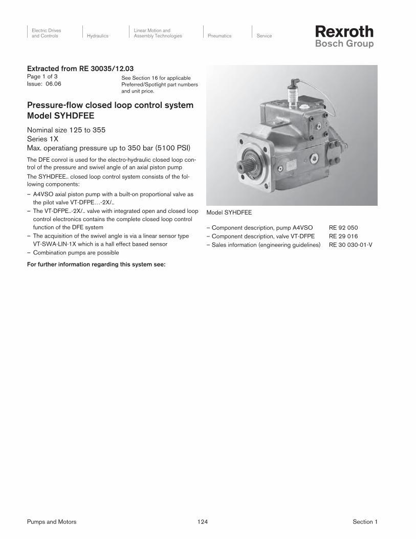
Pumps and Motors 124 Section 1
Electric Drivesand Controls Hydraulics
Linear Motion andAssembly Technologies Pneumatics Service
See Section 16 for applicable
Preferred/Spotlight part numbers
and unit price.
Extracted from RE 30035/12.03Page 1 of 3
Issue: 06.06
Pressure-fl ow closed loop control system
Model SYHDFEE
Nominal size 125 to 355
Series 1X
Max. operatiang pressure up to 350 bar (5100 PSI)
The DFE conrol is used for the electro-hydraulic closed loop con-
trol of the pressure and swivel angle of an axial piston pump
The SYHDFEE.. closed loop control system consists of the fol-
lowing components:
– A4VSO axial piston pump with a built-on proportional valve as
the pilot valve VT-DFPE…-2X/..
– The VT-DFPE..-2X/.. valve with integrated open and closed loop
control electronics contains the complete closed loop control
function of the DFE system
– The acquisition of the swivel angle is via a linear sensor type
VT-SWA-LIN-1X which is a hall effect based sensor
– Combination pumps are possible
For further information regarding this system see:
Model SYHDFEE
– Component description, pump A4VSO RE 92 050
– Component description, valve VT-DFPE RE 29 016
– Sales information (engineering guidelines) RE 30 030-01-V

Pumps and Motors 125 Section 1
Electric Drivesand Controls Hydraulics
Linear Motion andAssembly Technologies Pneumatics Service
See Section 16 for applicable
Preferred/Spotlight part numbers
and unit price.
Ordering code
Extracted from RE 30035/12.03Page 2 of 3
Issue: 06.06
Single pump 1)
Combination
pump 2)
Series 10 – 19 = 1X
Nom. size 125
Nom. size 180
Nom. size 250
Nom. size 355
= 125
= 180
= 250
= 355
Direction of rotation
Clockwise (preferred type)
Anti-clockwise
= R
= L
Pressure fluid
FKM seals
HFC
= V
= F
Shaft end3)
Cyl. shaft with key way DIN 6885
Splined shaft to DIN 5480 (standard type)
= P
= Z
Connection flange3)
NG 125 – 355 –> ISO 4-hole = B
Actuator line connections
Connections B and S: SAE on side, off-set through 90°,
metric fixing threads
2nd pressure connection B1 opposite B – when
delivered blanked off with a flange (standard) = 25
Further details
in clear text
Actual pressure input
C =
V =
D =
E =
F =
Current input:
4 – 20 mA
Voltage input:
0 –10 V
0 – 5 V
1 – 10 V
0.5 – 5 V 5)
Electronic sub-assembly
0 =
1 =
With
Without
leakage oil compensation
A =
B =
Additional function
power limitation
Without power limitation
With power limitation
0 = Valve mounting orientation
integrated electronics parallel to
pump axis in the direction of the
connection plate (standard)
A =
C =
Valve spool version
Standard (for mineral oil to DIN 51524
(HL/HLP))
4–groove spool for HFC pressure fluid
0000 =
0576 =
Basic pump version
Standard (internal pilot oil)
Remote supply
N00 =
U99 =
Through drive (see table on page 3)
Without through drive
Universal through drive without hub, without
intermediate flange with cover closed
Through drive without hub, with cover for mounting: (all com-
bination pumps (2nd) with SAE splined shaft profile)
KC1 4) =
KD3 4) =
KC3 4) =
Combination pump 6) Pilot in mm (in.)
A10VSO18 Ø82.55 (3.25)
A10VSO28/45 Ø100 (3.94)
Gear pump Ø101.6 (4.00)
With single pumps the hub and, if necessary,
the intermediate flange must be ordered seperately.
With combination pumps the front hub and, if necessary, the
intermediate flange are included within the scope of supply.
1) See ordering example at the top of page 32) See ordering example at the top of page 33) For dimensions see table on page 114) The through drive is is covered by a cover plate5) Connection via an M12 component socket 6) Example
SYHDFEE – 1X / – 25 – – 0 *
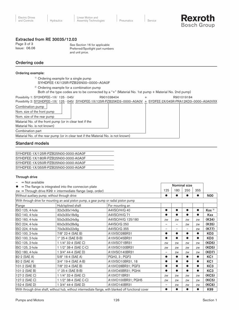
Pumps and Motors 126 Section 1
Electric Drivesand Controls Hydraulics
Linear Motion andAssembly Technologies Pneumatics Service
See Section 16 for applicable
Preferred/Spotlight part numbers
and unit price.
Ordering code
Extracted from RE 30035/12.03Page 3 of 3
Issue: 06.06
Ordering example:
1) Ordering example for a single pump
SYHDFEE-1X/125R-PZB25N00–0000–A0A0F
2) Ordering example for a combination pump
Both of the type codes are to be connected by a “+” (Material No. 1st pump + Material No. 2nd pump)
Possibility 1: SY2HDFEE–1X/ 125 - 045/ R901038404 + R901019184
Possibility 2: SY2HDFEE–1X/ 125 - 045/ SYHDFEE-1X/125R-PZB25KD3–0000–A0A0V + SYDFEE-2X/045R-PRA12KD3–0000–A0A0VXX
Combination pump
Nom. size of the front pump
Nom. size of the rear pump
Matarial No. of the front pump (or in clear text if the
Matarial No. is not known)
Combination part
Matarial No. of the rear pump (or in clear text if the Material No. is not known)
SYHDFEE-1X/125R-PZB25N00-0000-A0A0F
SYHDFEE-1X/180R-PZB25N00-0000-A0A0F
SYHDFEE-1X/250R-PZB25N00-0000-A0A0F
SYHDFEE-1X/355R-PZB25N00-0000-A0A0F
Through drive
– = Not available
l = The flange is integrated into the connecion plate
zw = Through drive K99 + intermediate flange (sep. order)
Nominal size
125 180 250 355
Without auxiliary pump; without through drive l l l l N00
With through drive for mounting an axial piston pump, a gear pump or radial piston pump
Flange Hub/splined shaft For mounting an
ISO 125, 4-hole 32x2x30x14x9g A4VSO/H/G 40 l l l l Kxx 3)
ISO 140, 4-hole 40x2x30x18x9g A4VSO/H/G 71 l l l l Kxx
ISO 160, 4-hole 50x2x30x24x9g A4VSO/H/G 125/180 zw zw zw zw (K34)
ISO 224, 4-hole 60x2x30x28x9g A4VSO/G 250 – – zw zw (K35)
ISO 224, 4-hole 70x3x30x22x9g A4VSO/G 355 – – – zw (K77)
ISO 100, 2-hole 7/8“ 22-4 (SAE B) A10VSO28BR31 l l l l KD3
ISO 100, 2-hole 1“ 25-4 (SAE B-B) A10VSO45BR31 l l l l KD3
ISO 125, 2-hole 1 1/4“ 32-4 (SAE C) A10VSO71BR31 zw zw zw zw (KD5)
ISO 125, 2-hole 1 1/2“ 38-4 (SAE C-C) A10VSO100BR31 zw zw zw zw (KD5)
ISO 180, 4-hole 1 3/4“ 44-4 (SAE D) A10VSO140BR31 – zw zw zw (KD7)
82-2 (SAE A) 5/8“ 16-4 (SAE A) PGH2, 3 ; PGF2 l l l l KC1
82-2 (SAE A) 3/4“ 19-4 (SAE A-B) A10VSO10BR31, 18 l l l l KC1
101-2 (SAE B) 7/8“ 22-4 (SAE B) A10VO28BR31; PGF3 l l l l KC3
101-2 (SAE B) 1“ 25-4 (SAE B-B) A10VO45BR31; PGH4 l l l l KC3
127-2 (SAE C) 1 1/4“ 32-4 (SAE C) A10VO71BR31 zw zw zw zw (KC5)
127-2 (SAE C) 1 1/2“ 38-4 (SAE C-C) A10VO100BR31; PGH5 zw zw zw zw (KC5)
152-4 (SAE D) 1 3/4“ 44-4 (SAE D) A10VO140BR31 – zw zw zw (KC6)
With through drive shaft, without hub, without intermediate flange, with blanked off functional cover l l l l K99
Standard models