Embed Size (px)
Citation preview
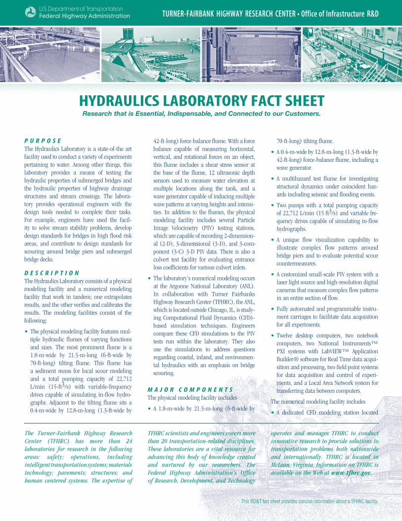
HYDRAULICS LABORATORY FACT SHEETResearch that is Essential, Indispensable, and Connected to our Customers.
TURNER-FAIRBANK HIGHWAY RESEARCH CENTER • Office of Infrastructure R&D
The Turner-Fairbank Highway Research Center (TFHRC) has more than 24 laboratories for research in the following areas: safety; operations, including intelligent transportation systems; materials technology; pavements; structures; and human centered systems. The expertise of
TFHRC scientists and engineers covers more than 20 transportation-related disciplines. These laboratories are a vital resource for advancing this body of knowledge created and nurtured by our researchers. The Federal Highway Administration’s Office of Research, Development, and Technology
operates and manages TFHRC to conduct innovative research to provide solutions to transportation problems both nationwide and internationally. TFHRC is located in McLean, Virginia. Information on TFHRC is available on the Web at www.tfhrc.gov.
This RD&T fact sheet provides concise information about a TFHRC facility.
P u r P o s eThe Hydraulics Laboratory is a state-of-the art facility used to conduct a variety of experiments pertaining to water. Among other things, this laboratory provides a means of testing the hydraulic properties of submerged bridges and the hydraulic properties of highway drainage structures and stream crossings. The labora-tory provides operational engineers with the design tools needed to complete their tasks. For example, engineers have used the facil-ity to solve stream stability problems, develop design standards for bridges in high flood risk areas, and contribute to design standards for scouring around bridge piers and submerged bridge decks.
D e s c r i P t i o nThe Hydraulics Laboratory consists of a physical modeling facility and a numerical modeling facility that work in tandem; one extrapolates results, and the other verifies and calibrates the results. The modeling facilities consist of the following:
The physical modeling facility features mul-•tiple hydraulic flumes of varying functions and sizes. The most prominent flume is a 1.8-m-wide by 21.3-m-long (6-ft-wide by 70-ft-long) tilting flume. This flume has a sediment recess for local scour modeling and a total pumping capacity of 22,712 L/min (15-ft3/s) with variable-frequency drives capable of simulating in-flow hydro-graphs. Adjacent to the tilting flume sits a 0.4-m-wide by 12.8-m-long (1.3-ft-wide by
42-ft-long) force-balance flume. With a force balance capable of measuring horizontal, vertical, and rotational forces on an object, this flume includes a shear stress sensor at the base of the flume, 12 ultrasonic depth sensors used to measure water elevation at multiple locations along the tank, and a wave generator capable of inducing multiple wave patterns at varying heights and intensi-ties. In addition to the flumes, the physical modeling facility includes several Particle Image Velocimetry (PIV) testing stations, which are capable of recording 2-dimension-al (2-D), 3-dimensional (3-D), and 3-com-ponent (3-C) 3-D PIV data. There is also a culvert test facility for evaluating entrance loss coefficients for various culvert inlets.
The laboratory’s numerical modeling occurs •at the Argonne National Laboratory (ANL). In collaboration with Turner Fairbanks Highway Research Center (TFHRC), the ANL, which is located outside Chicago, IL, is study-ing Computational Fluid Dynamics (CFD)-based simulation techniques. Engineers compare these CFD simulations to the PIV tests run within the laboratory. They also use the simulations to address questions regarding coastal, inland, and environmen-tal hydraulics with an emphasis on bridge scouring.
M A J o r c o M P o n e n t sThe physical modeling facility includes
A 1.8-m-wide by 21.3-m-long (6-ft-wide by •
70-ft-long) tilting flume.
A 0.4-m-wide by 12.8-m-long (1.3-ft-wide by •42-ft-long) force-balance flume, including a wave generator.
A multihazard test flume for investigating •structural dynamics under coincident haz-ards including seismic and flooding events.
Two pumps with a total pumping capacity •of 22,712 L/min (15 ft3/s) and variable fre-quency drives capable of simulating in-flow hydrographs.
A unique flow visualization capability to •illustrate complex flow patterns around bridge piers and to evaluate potential scour countermeasures.
A customized small-scale PIV system with a •laser light source and high-resolution digital cameras that measure complex flow patterns in an entire section of flow.
Fully automated and programmable instru-•ment carriages to facilitate data acquisition for all experiments.
Twelve desktop computers, two notebook •computers, two National Instruments™ PXI systems with LabVIEW™ Application Builder® software for Real Time data acqui-sition and processing, two field point systems for data acquisition and control of experi-ments, and a Local Area Network system for transferring data between computers.
The numerical modeling facility includes
A dedicated CFD modeling station located •
at the ANL. Engineers create CFD models of particular physical setups and analyze them twice using FLUENT and STAR CD. Then they compare the models to check for consistency.
A c c o M P L i s H M e n t sThe laboratory’s accomplishments include the following:
Conducted several forensic investigations of •major bridge collapses, including the 1989 Hatchie River bridge failure in Tennessee and the 1995 I-5 bridge collapse in California.
Investigated bridge scour countermeasure •ideas and development.
Developed criteria currently in the Federal •Highway Administration’s (FHWA’s) Hydraulics Engineering Circular (HEC)-23 for protection of piers and abutments from scour.
Developed guidelines currently in FHWA’s •HEC-18 for estimating scour around piers with complex geometries.
Conducted junction loss experiments for •storm sewer analyses using 3-D PIV experi-ments to evaluate proposed modifications to those routines.
Conducted model studies (physical and numer-•ical) for scour evaluation of the Woodrow Wilson Bridge, which spans the Potomac River between Virginia and Maryland.
Conducted a model study for a proposed •bridge over the Milwaukee River where a
major sanitary line could be undermined by bridge scour.
Conducted culvert entrance loss studies •for Iowa, South Dakota, and the Federal Emergency Management Agency (FEMA).
Conducted scour in bottomless culverts studies for the Maryland State Highway Administration.
e x P e r t i s eThe laboratory staff consists of the following members who have expertise in fluid measure-ment techniques, including high-speed digital photography of illuminated flow sections using a high energy pulsed laser for 2-D and 3-D PIV.
Laboratory Manager with a doctorate in fluid •mechanics and more than 15 years of labora-tory experience.
Research Engineer (contract) with a master’s •in electronics and computer science.
Research Technicians and Electronic •Engineers (contract) with contemporary experience in instrumentation and data pro-cessing.
Furthermore, the laboratory has access to pro-fessionals experienced in systems analysis, risk analysis, urban drainage design, and CFD mod-eling.
Laboratory Manager: Kornel KerenyiE-mail: [email protected]: 202-493-3142Web site: http://www.fhwa.dot.gov/engineering/hydraulics/research/lab.cfm
L A B o r A t o r Y P A r t n e r sThe Hydraulics Laboratory has partnered with the Alaska Department of Transportation (DOT), Georgia DOT, Iowa DOT, Maryland State Highway Administration (SHA), Michigan DOT, Minnesota DOT, Pennsylvania DOT, South Dakota DOT, Texas DOT, Utah DOT, Vermont Agency of Transportation, Arlington County, Department of Energy (through ANL), FEMA, National Oceanic and Atmospheric Administration (NOAA), and United States Geological Survey (USGS).
FHWA-HRT-07-054HRDI-07/10-07(1M)E


