Embed Size (px)
Citation preview

CL04
HydraulicsProduct CatalogueValve series

Contents
All the technical information listed here has been defined using standards or the manufacturer’s testing procedures. Subject to deviations under the customer’s specific operating conditions. We only accept liability for the warranted properties if these properties have been agreed in writing, separately to the factory catalogues. We do not accept liability for the overall function of the plant or machine when supplying individual components.
CLAAS Industrietechnik 4
Valve Series CL04 Overview 5
Components 6
General technical data 6
Components CL04 Screw-in Cartridges 8
Valve Sections 38
Accessories 50
Modular mobile hydraulic system 54

54 Valve Series CL04
Increasingly powerful vehicles call for hydraulics with greater power density, while pressure and volume flow are constantly rising at the same time. The growing number of electrohydraulic functions in vehicles and systems demand a reduction in electricity consumption. For the purposes of energy efficiency, the CL04 valve series was designed as a modular valve series.
■ Switching valves in leak-proof poppet design ■ Check, pressure and flow valves ■ With the CLAAS system flanged valve sections ■ Customer-specific special cartridges, such as the poppet
type 2 way proportional valve for small flow rates ■ This modular structure provides tailor-made solutions for your
applications. ■ High-grade components and a 100% check on all cartridges
guarantees the reliable operation of your machinery.
Overview of valve series CL04
CLAAS Industrietechnik is your innovative, reliable partner for the development and supply of hydraulic components and drive technology systems. Our strengths: our 600 employees in Paderborn, Germany develop and produce specific solutions tailored to the needs of customers and industries. Hence you will find our products and systems in agricultural and construction machinery, in municipal service technology and a wide range of special applications. Our customers appreciate the high-level product benefits and top-class technology we offer. As different as the customer-specific applications are our products always share the same strengths: innovation, reliability and quality to meet the highest requirements.
Modular efficiency: hydraulic valves from CLAAS Industrietechnik
High-quality switching and proportional valve technology is one of the core competences of CLAAS Industrietechnik. Our system approach includes the whole range from design and simulation to integration in our customers’ applications. Herewith we develop solutions for a wide variety of challenges in hydraulic and electronic system technology.
Our test facilities are used to validate all components and systems thoroughly during the development process. Our switching valves, directional valves, pressure and flow control valves are used as basic components. At the start of a development project, our engineers try to get a complete understanding of the application together with our customers. After this, they develop individual solutions on the basis of our modular philosophy. The wide range of combination options available with the basic elements of our modular mobile hydraulic system is adapted to your application in a technically and economically efficient way. With it we offer a holistic project handling for all hydraulic tasks.
Combination of hydraulics and electronics
Solving complex control tasks demands a close interaction of hydraulics and electronics. The combination of the modular mobile hydraulic system and our electronic control systems developed and tested in our own company provides the basis for customized solutions that are precisely tailored to your needs.
At home in every field – system solutions from CLAAS Industrietechnik

76 Valve Series CL04
General technical data
Pressure ValvesPage 22
Directional ValvesPage 10
Valve SectionsPage 38
Check valves Page 34
Flow Control Valve
Page 32
Permissible oil types Mineral oil HL, HLP, HVLP according to DIN 51524;
polialphaolefines, e.g. Avia Syntofluid;
other fluids on request
Oil cleaniness min. 21/18/15 according to ISO4406; no particles >200 µm
Nominal voltage 12 VDC and 24 VDC
Electric connectors Standard Compagnie Deutsch DT04-2P IPX9K
Optional 3-pin DIN connector accordinbg to DIN EN175301-803 (IP65)
Optional AMP Junior Timer 2-pin (IP65)
Electrical protection class IP65 to 69 according to EN 60529, depending on the connector
Only applies in conjunction with a fitted connector
Operating pressure max. 350 bar
Ambient temperature min. - 25° C
max. + 50° C
Permissible oil temperature min. - 25° C
max. + 85° C
Permissible oil viscosity min. 10 cSt
max. 500 cSt
optimal 35 cSt
Components of valve series CL04AccessoriesPage 50

98 Valve Series CL04
Screw-in Cartridges Screw-in Cartridges
Screw-in Cartridges of the CL04 valve series
CL04 Cartridges The valves in the CL04 valve series are screw-in cartridges for a maximum operating pressure of 350 bar. Despite their high switching performance of up to 50 l/min, all electrically actuated valves are directly controlled, making them particularly robust and ideal for mobile hydraulic applications. All spools, poppets and sleeves are hardened and all external parts are protected against corrosion. To ensure that the cartridges can always be relied upon to operate correctly even under rough conditions, we have subjected them to a stringent validation process during development. In order to maintain this standard in future, each individual valve is fully automatically tested during serial assembly.
Directional ValvesHigh-performance poppet type valves in both 2/2 directional and 3/2 directional versions – with negative or positive overlap – form the basis for the series. These are supplemented by switching and proportional cartridges in a spool design. The proportional 2/2 directional poppet valve designed for small flow rates holds a special position.
Pressure ValvesPressure relief and mechanical/electrical proportional pressure control valves for different pressure ranges.
Flow control ValvesHigh pressure resistant flow control valves are available in two sizes, set to a fixed volume flow.
Check ValveCheck valves, direct and pilot operated, with hardened spools are available with different opening pressures, as well as for different flow rates.

1110
Q [l/min]
Q [l/min]
Q [l/min]
Q [l/min]
Δp [b
ar]
p [b
ar]
Δp [b
ar]
p [b
ar]
NP0 PP0
Valve Series CL04
Screw-in Cartridges Screw-in Cartridges
3/2 directional valve, poppet type positive / negative overlap
The high-performance 3/2 directional valves have hardened poppets and sleeves. All external parts have a Cr VI-free zinc coating and thus they are also suitable for use under rough environmental conditions. In functional terms, the positiv overlapped version is particularly suitable for use in constant pressure systems because of the lack of pressure shocks in switching operations. Both versions are resistant to silting over long periods under pressure.
Technical Data
Model 3/2 directional valve, poppet typeInstallation position anyCavity CL04 3 portsWeight (excluding coil) 0.26 kgNominal flow rate 35 l/minFlow rate max. 50 l/minNominal operating pressure 350 bar at all portsSwitching time * 50 – 100 msSwitching frequency * max. 10000/hInternal leakage * max. 3 drops/min at ∆P 250 barNominal voltage 12 VDC; 24 VDCSupply voltage tolerance ±10 %Duty cycle 100 %Nominal power consumption (at 20°C) 33 WNominal current (operating temp.) at 12 VDC type: 1.6 A
at 24 VDC type: 0.82 ACoil type CC04-MSP-045-SW0Standard electrical connection Deutsch DT04-2P with free wheeling diodeCoil diameter 45 mm
* Data and characteristic curves measured with oil viscosity approx. 35cSt
Dimensional drawing
Characteristic curves
pressure drop - flow rate characteristic
valve performance
pressure drop - flow rate characteristic
valve performance
Order code CC04 - W32 - - - -
Series CLAAS Cartridge Range CL04
Type 3/2 directional valve
Model Poppet type with positive overlap PP0
Poppet type with negative overlap NP0
Version Solenoid, standard version with manual override STN
Nominal voltage 12 V 12 V
24 V 24 V
No coil OSP
Connector type DIN 43650 DIN
DT04-2P with Diode DTD
AMP-Junior-Timer AMP
No coil 000

1312
Q [l/min]
Q [l/min]
Q [l/min]
Q [l/min]
Δp [b
ar]
p [b
ar]
Δp [b
ar]
p [b
ar]
Valve Series CL04
Screw-in Cartridges Screw-in Cartridges
2/2 directional valve, poppet typenormally closed
The 2/2 directional valves have hardened poppets and sleeves. All external parts have a Cr VI-free zinc coating and thus are suitable for use under rough environmental conditions. The standard version features high performance figures, while the Low Watt version is ideal for applications in which high quality is required; however switching performance is lower than the standard version in favour of installation space and power consumption.
Technical data
Standard (STN) Low Watt (LWN)Model 2/2 directional valve, poppet typeInstallation position anyCavity CL04 2 portsWeight (excluding coil) 0.24 kg 0.21 kgNominal flow rate 50 l/min 25 l/minNominal operating pressure 350 bar 270 barSwitching time * 30 – 100 msSwitching frequency * max. 10000/hInternal leakage * max. 3 drops/min at ∆P 250 barNominal voltage 12 VDC; 24 VDCSupply voltage tolerance ±10 %Duty cycle 100 %Nominal power consumption (at 20°C) 33 W 20 WNominal current (operating temp.) at 12 VDC type: 1.6 A
at 24 VDC type: 0.82 Aat 12 VDC type: 1.0 Aat 24 VDC type: 0.52 A
Coil type CC04-MSP-045-SW0 CC04-MSP-037-SW0Standard electrical connection Deutsch DT04-2P with free wheeling diodeCoil diameter 45 mm 37 mm
* Data and characteristic curves measured with oil viscosity approx. 35cSt
Dimensional drawing
Characteristic curves
pressure drop - flow rate characteristic
valve performance
pressure drop - flow rate characteristic
valve performance
Order code CC04 - W22 - CP0 - - -
Series CLAAS Cartridge Range CL04
Type 2/2 directional valve
Model Poppet type normally closed CP0
Version Solenoid, standard version with manual override STN
Solenoid, low Watt (LW) version with manual override LWN
Nominal voltage 12 V 12 V
24 V 24 V
No coil OSP
Connector type DIN 43650 DIN
DT04-2P with Diode DTD
AMP-Junior-Timer AMP
No coil 000
STN LWN

1514
Q [l/min] Q [l/min]
Δp [b
ar]
p [b
ar]
Valve Series CL04
Screw-in Cartridges Screw-in Cartridges
2/2 directional valve, poppet typenormally open
De-energized the valve is kept open by a spring, allowing flow from 1 to 2 or wise versa. This functionality is required in safety-related applications in which it is necessary to switch to a safe, i.e. depressurized, state in the event of a fault. Resistance to silting and the robust direct operated poppet makes the cartridge suitable for such applications. Like all CL04 solenoid cartridges, the poppets and sleeves are hardened and grinded. All external parts have a Cr VI-free zinc coating and thus are suitable for use under rough environmental conditions.
Characteristic curves
Technical data
Model 2/2 directional valve, poppet typeInstallation position anyCavity CL04 2 portsWeight (excluding coil) 0.24 kgNominal flow rate 50 l/minNominal operating pressure 350 barSwitching time * 40 – 100 msSwitching frequency * max. 10000/hInternal leakage * max. 3 drops/min at ∆P 250 barNominal voltage 12 VDC; 24 VDCSupply voltage tolerance ±10 %Duty cycle 100 %Nominal power consumption (at 20°C) 33 WNominal current (operating temp.) 12 VDC type: 1.6 A
24 VDC type: 0.82 ACoil type CC04-MSP-045-SW0Standard electrical connection Deutsch DT04-2P with free wheeling diodeCoil diameter 45 mm
* Data and characteristic curves measured with oil viscosity approx. 35cSt
Dimensional drawing
Order code CC04 - W22 - OP0 - STN - -
Series CLAAS Cartridge Range CL04
Type 2/2 directional valve
Model Poppet type, normally open OP0
Version Solenoid, standard version with manual override STN
Nominal voltage 12 V 12 V
24 V 24 V
No coil OSP
Connector type DIN 43650 DIN
DT04-2P with diode DTD
AMP-Junior-Timer AMP
No coil 000
pressure drop - flow rate characteristic valve performance

1716
Q [l/min] Q [l/min]
Δp [b
ar]
p [b
ar]
Valve Series CL04
Screw-in Cartridges Screw-in Cartridges
3/2 directional valve, spool type
The 3/2 directional spool valve has hardened spools and sleeves. It can be used wherever zero leakage and maximum switching power of the CL04 3/2 directional poppet valve are not required, but rather a more compact, more energy-saving solution is needed. All CL04 3/2-directional valves require the same cavity. This means that we can offer you a custom tailored solution, while still having the option of replacing the cartridges to fulfil changing requirements without changing the block design. All external parts have a Cr VI-free zinc coating and thus are suitable for use under rough environmental conditions.
Technical data
Model 3/2 directional valve, spool typeInstallation position anyCavity CL04 3 portsWeight (excluding coil) 0.23 kgNominal flow rate 20 l/minNominal operating pressure 270 barSwitching time * 40 – 100 msSwitching frequency * max. 10000/hInternal leakage * max. 150 ml/min at ∆P 250 barNominal voltage 12 VDC; 24 VDCSupply voltage tolerance ±10 %Duty cycle 100 %Nominal power consumption (at 20°C) 20 WNominal current (operating temp.) at 12 VDC type: 1.0 A
at 24 VDC type: 0.52 ACoil type CC04-MSP-037-SW0Standard electrical connection Deutsch DT04-2P with with free wheeling diodeCoil diameter 37 mm
* Data and characteristic curves measured with oil viscosity approx. 35cSt
Dimensional drawing
Characteristic curves
Order code CC04 - W32 - NS0 - LWN - -
Series CLAAS Cartridge Range CL04
Type 3/2 directional valve
Model Spool type with negative overlap NS0
Version Solenoid, low Watt (LW) version with manual override LWN
Nominal voltage 12 V 12 V
24 V 24 V
No coil OSP
Connector type DIN 43650 DIN
DT04-2P with Diode DTD
AMP-Junior-Timer AMP
No coil 000
pressure drop - flow rate characteristic valve performance

1918
l [mA] l [mA]
Q [l
/min]
Q [l
/min]
Valve Series CL04
Screw-in Cartridges Screw-in Cartridges
2/2 directional valve, poppet typeproportional, normally closed
The proportional 2/2 directional poppet valve holds a special position within the CL04 valve series. Requiring the same installation space as the 2/2 directional poppet valve, it enables the regulation of small flow rates in both flow directions and to hold loads securely and without leakage when it is de-energized. All of this is combined with a robust direct actuation as well as hardened poppets and sleeves. The external parts have a Cr VI-free zinc coating. Currently this proportional cartridge is only available for a nominal flow rate of 3l/min, based on a pressure difference of 100 bar. However, other nominal flows can be realized on request.
Technical data
Model 2/2 directional valve, poppet type, proportionalInstallation position anyCavity CL04 2 portsWeight (excluding coil) 0.21 kgNominal flow rate 3 l/minNominal operating pressure 350 barInternal leakage * max. 3 drops/min at ∆P 250 barNominal voltage 12 VDC; 24 VDCSupply voltage tolerance ±10 %Duty cycle 100 %Nominal current (operating temp.) 12 VDC type: 0 – 1.9 A
24 VDC type: 0 – 1.0 AElectrical resistance (at 20°C) at 12 VDC: 3.2 Ω
at 24 VDC: 12.8 ΩOptimum PWM frequency 100 – 130 HzCoil type CC04-MSP-037-PR0Standard electrical connection Deutsch DT04-2PCoil diamete 37 mm
* Data and characteristic curves measured with oil viscosity approx. 35cSt
Dimensional drawing
Characteristic curves
Order code CC04 - P22 - CP0 - 03N - -
Series CLAAS Cartridge Range CL04
Type 2/2 directional valve, proportional P22
Model Poppet type normally closed CP0
Version 3 l/min *, Solenoid, with manual override 03N
Nominal voltage 12 V 12 V
24 V 24 V
No coil OSP
Connector type DIN 43650 DIN
DT04-2P DTD
AMP-Junior-Timer AMP
No coil 000
* other volumetric flows on request
flow rate 1-2 flow rate 2-1
2120
l [mA]
Q [l
/min]
Valve Series CL04
Screw-in Cartridges Screw-in Cartridges
3/2 directional valve, spool typeproportional
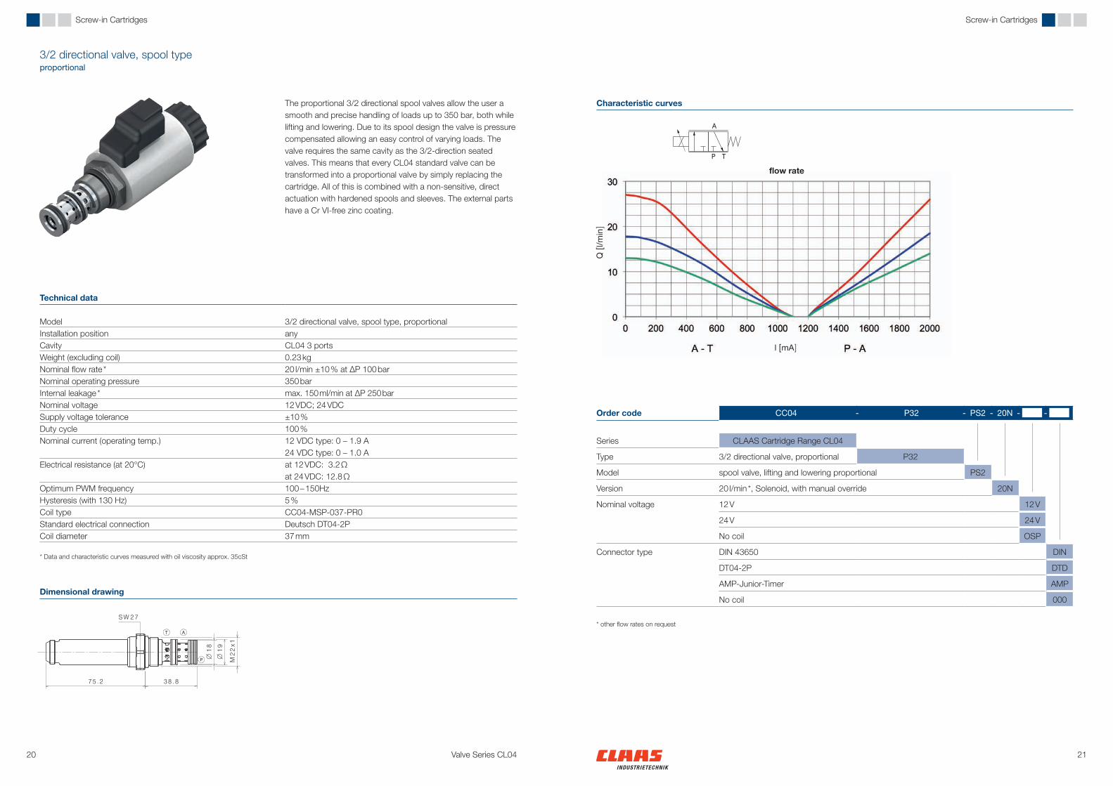
The proportional 3/2 directional spool valves allow the user a smooth and precise handling of loads up to 350 bar, both while lifting and lowering. Due to its spool design the valve is pressure compensated allowing an easy control of varying loads. The valve requires the same cavity as the 3/2-direction seated valves. This means that every CL04 standard valve can be transformed into a proportional valve by simply replacing the cartridge. All of this is combined with a non-sensitive, direct actuation with hardened spools and sleeves. The external parts have a Cr VI-free zinc coating.
Technical data
Model 3/2 directional valve, spool type, proportionalInstallation position anyCavity CL04 3 portsWeight (excluding coil) 0.23 kgNominal flow rate * 20 l/min ±10 % at ∆P 100 barNominal operating pressure 350 barInternal leakage * max. 150 ml/min at ∆P 250 barNominal voltage 12 VDC; 24 VDCSupply voltage tolerance ±10 %Duty cycle 100 %Nominal current (operating temp.) 12 VDC type: 0 – 1.9 A
24 VDC type: 0 – 1.0 AElectrical resistance (at 20°C) at 12 VDC: 3.2 Ω
at 24 VDC: 12.8 ΩOptimum PWM frequency 100 – 150HzHysteresis (with 130 Hz) 5 %Coil type CC04-MSP-037-PR0Standard electrical connection Deutsch DT04-2PCoil diameter 37 mm
* Data and characteristic curves measured with oil viscosity approx. 35cSt
Dimensional drawing
Characteristic curves
Order code CC04 - P32 - PS2 - 20N - -
Series CLAAS Cartridge Range CL04
Type 3/2 directional valve, proportional P32
Model spool valve, lifting and lowering proportional PS2
Version 20 l/min *, Solenoid, with manual override 20N
Nominal voltage 12 V 12 V
24 V 24 V
No coil OSP
Connector type DIN 43650 DIN
DT04-2P DTD
AMP-Junior-Timer AMP
No coil 000
* other flow rates on request
flow rate

2322
Q [l/min]
dP [b
ar]
Valve Series CL04
Screw-in Cartridges Screw-in Cartridges
Pressure relief valve DBX, poppet typespring loaded
The pressure relief valves of the DBX series can be used for flow rates up to 70l/min. Sleeve and poppet are both hardened and due to the special poppet design both stroke direction are damped. By default all DBX are set to a fixed opening pressure during assembly and all valves are checked for function. Three different springs are currently used to cover a pressure range from 20 to 350 bar. All external parts have a Cr VI-free coating.
Technical data
Mode pressure relief valve, spring loaded, poppet typeInstallation position Preferably suspendedCavity CL04 2 portsWeight 0.32 kgNominal flow rate 50 l/minFlow rate max. 70 l/minAdjustable nominal pressure * min. 20 bar (at 10 l/min)
max. 380 bar (at 10 l/min)Internal leakage * max. 3 drops/min at 70% preset pressure
* Data and characteristic curves measured with oil viscosity approx. 35cSt
Dimensional drawing
Characteristic curves
Pressure range CPressure range BPressure range A
Order code CC04 - DBX - ME0 - -
Series CLAAS Cartridge Range CL04
Model pressure relief valve, poppet type DBX
Version direct acting, spring loaded ME0
Pressure range* 210 – 380 bar 00A
75 – 220 bar 00B
20 – 150 bar 00C
Preset pressure depending on the selected pressure range XXX bar (e.g. 150 bar -> 150)
* other flow rates on request
pressure drop - flow rate characteriticsSample pressures set at 10 l/min
2524
Q [l/min]
Δp [b
ar]
Valve Series CL04
Screw-in Cartridges Screw-in Cartridges
Pressure relief valve DBP, poppet typespring loaded
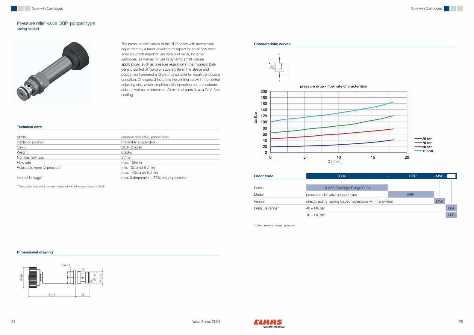
The pressure relief valves of the DBP series with mechanical adjustment by a hand wheel are designed for small flow rates. They are predestined for use as a pilot valve, for larger cartridges, as well as for use in dynamic small volume applications, such as pressure regulation in the hydraulic bale density control of round or square balers. The sleeve and poppet are hardened and are thus suitable for rough continuous operation. One special feature is the venting screw in the central adjusting unit, which simplifies initial operation on the customer side, as well as maintenance. All external parts have a Cr VI-free coating.
Technical data
Model pressure relief valve, poppet typeInstllation position Preferably suspendedCavity CL04 2 portsWeight 0.28kgNominal flow rate 5 l/min Flow rate max. 15 l/minAdjustable nominal pressure* min. 10 bar (at 5 l/min)
max. 140 bar (at 5 l/min)Internal leakage* max. 3 drops/min at 70% preset pressure
* Data and characteristic curves measured with oil viscosity approx. 35cSt
Dimensional drawing
Characteristic curves
Order code CC04 - DBP - MV0 -
Series CLAAS Cartridge Range CL04
Model pressure relief valve, poppet type DBP
Version directly acting, spring loaded; adjustable with handwheel MV0
Pressure range * 40 – 140 bar 00A
10 – 110 bar 00B
* other pressure ranges on request
pressure drop - flow rate characteritics

2726
l [A]
l [A]
Δp [b
ar]
Δp [b
ar]
Valve Series CL04
Screw-in Cartridges Screw-in Cartridges
Pressure relief valve, poppet typeelectric, proportional / inverse proportional
Electric proportional pressure relief valves of type DBP are predestined for use as pre-control valves or for pressure regulation in small volume, dynamic applications, such as the pressure regulation in the hydraulic bale density control of round or square balers. The inverse proportional solenoid maintains the pressure when it is de-energized, thus enabling emergency operation in the event of a cable break. The actuators of both solenoids have a venting screw.
Dimensional drawing
Characteristic curves
pressure characteristic
pressure characteristic
Order code CC04 - DBP - - - - -
Series CLAAS Cartridge Range CL04
Model pressure relief valve, poppet type DBP
Version proportional, electric, directly actuated E00
inversely proportional, electric, directly actuated I00
Pressure range up to 75 bar 00A
up to 100 bar 00B
up to 215 bar 00C
Preset pressure depending on the selected pressure range XXX bar (e.g. 150 bar -> 150)
Nominal voltage 12 V 12 V
24 V 24 V
No coil OSP
Connector type DIN 43650 DIN
DT04-2P DT0
AMP-Junior-Timer AMP
No coil 000
Technical data
Prop-DBV Inverse-Prop-DBVModel pressure relief valve, poppet type, electric, proportional/inverse propotionalInstallation position Preferably suspendedCavity CL04 2 portsWeight (excluding coil) 0.32 kg 0.42 kgNominal flow rate* Pressure range A, B: 5 l/min
Pressure range C: 2 l/minPressure range A, B: 2 l/min Pressure range C: 1 l/min
Maximum flow rate 10 l/min; 5l/min at pressure range CAdjustable nominal pressure* 0 – 215 bar electric proportional
Pressure increase; el. proportional 0 – 215 bar fixed pressure, manually adjustable, pressure decrease el.proportional
Internal leakage* max. 3 drops/min at 70% preset pressureNominal voltage 12 VDC; 24 VDCSupply voltage tolerance ±10 %Duty cycle 100 %Nominal current (operating temp.) 12 VDC type: 0 – 1.9 A / 24 VDC type: 0 – 1.0 AElectrical resistance (at 20°C) at 12 VDC: 4.55 Ω / at 24 VDC: 17.6 ΩOptimum PWM frequency* 200 HzCoil type CC04-MSP-045-PR0Standard electrical connection Deutsch DT04-2PCoil diameter 45 mm
* Data and characteristic curves measured with oil viscosity approx. 35cSt
E00
I00

2928 Valve Series CL04
Screw-in Cartridges Screw-in Cartridges
Pressure reducing valves DRX, spool typespring loaded
The pressure reducing valves of type DRX are direct acting, spring loaded spool valves. Small moving masses and the direct control make the DRX extremely dynamic – pressure peaks in the hydraulic system are safely balanced. With a nominal flow rate of 25 l/min, they use a high-pressure circuit of up to 350 bar to feed a low-pressure circuit for small motors or the pilot valves of a large mobile hydraulic block. Different internal area ratios allow two pressure levels.
Dimensional drawing
Symbol
Technical data
Typ DE0 Typ DV0Model pressure reducing valve, spool type,
spring loaded, adjustablepressure reducing valve, spool type, spring loaded, adjustable with hand wheel
Installation position Preferably suspendedCavity CL04 3 portsWeight 0.32kg 0.31kgNominal flow rate 25 l/min Flow rate max. 30 l/minNominal pressure max. 350 barAdjustable nominal pressure at A* 0 – 60 bar
0 – 200 barInternal leakage* max. 200 ml/min at 50 bar at A, static
* Data and characteristic curves measured with oil viscosity approx. 35cSt
DV0 DE0
Order code CC04 - DRX - - -
Series CLAAS Cartridge Range CL04
Model pressure reducing valve, spool type DRX
Version adjustable DE0
adjustable with hand wheel DV0
Pressure range up to 60 bar 060
up to 200 bar 200
Preset pressure XXX bar (e.g. 15 bar -> 015)
DRX Available 3rd quarter 2014

3130 Valve Series CL04
Screw-in Cartridges Screw-in Cartridges
Pressure reducing valve DRX, spool typeelectric proportional
The DRX pressure reducing valves are electric proportional spool valves. Small moving masses and the direct control make the DRX extremely dynamic – pressure peaks in the hydraulic system are safely balanced. With a nominal volume flow of 25 l/min, they use a high-pressure circuit of up to 350 bar to feed a low-pressure circuit. It is also perfect as a dynamic pilot valve for large cartridges or spool valves. Different internal area ratios allow two pressure levels.
Technical data
Model pressure reducing valve, spool type, electric proportional, central venting screw
Installation position Preferably suspendedCavity CL04 3 portsWeight (excluding coil) 0.34 kgNominal flow rate 25 l/min Flow rate max. 30 l/minOperating pressure max. 350 barAdjustable nominal pressure * 0 – 17 bar / 0 – 65 barInternal leakage * max. 200 ml/min at 50 bar at A, staticNominal voltage 12 VDC; 24 VDCSupply voltage tolerance ±10 %Duty cycle 100 %Nominal current (operating temp.) 12 VDC type: 0 – 1.9 A / 24 VDC type: 0 – 1.0 AElectrical resistance (at 20°C) at 12 VDC: 4.55 Ω / at 24 VDC: 17.6 ΩOptimum PWM frequency * 100 – 150 HzCoil type CC04-MSP-045-PR0Standard electrical connection Deutsch DT04-2PCoil diameter 45 mm
* Data and characteristic curves measured with oil viscosity approx. 35cSt
Dimensional drawing
Symbol
DRX Available in 3rd quarter 2014
Order code CC04 - DRX - E00 - - -
Series CLAAS Cartridge Range CL04
Model pressure reducing valve, spool type DRX
Version electric proportional, direct acting E00
Pressure range up to 17 bar 017
up to 65 bar 065
Nominal voltage 12 V 12 V
24 V 24 V
No coil OSP
Connector type DIN 43650 DIN
DT04-2P DT0
AMP-Junior-Timer AMP
No coil 000

3332
Q [l
/min]
Δp [bar]
Valve Series CL04
Screw-in Cartridges Screw-in Cartridges
Flow conrtol valve SRV / SRX2 way, spool type
The 2 way flow control valves are designed as spring loaded spool valves. SRV and SRX cover different nominal flow rates with the same cavity. Both versions are fully pressure compensated so they are almost independent of the actual pressure drop between inlet and outlet. Different nominal volume flows within a model size are realized by different orifices. Both flow control valves are highly dynamic due to small moving masses and the direct control. For reliable continuous operation, the working parts are hardened. All visible parts have a Cr VI-free coating.
Dimensional drawing
Characteristic curves
Technical data
Typ SRV Typ SRXModel 2 way flow control valve, spool typeInstallation position Preferably suspendedCavity CL04 2 portsWeight 0.08 kg 0.12 kgNominal flow rate * 7 l/min 28 l/minControl pressure differential 7 barMax operating pressure max. 350 bar
* Data and characteristic curves measured with oil viscosity approx. 35cSt Order code CC04 - -
Series CLAAS Cartridge Range CL04
Model flow control valve SRX
flow control valve SRV
Nominal flow rate* 7 l/min (SRV) 007
28 l/min (SRX) 028
* Other flow rates on request
flow control characteristics

3534
Q [l/min]Q [l/min]
0,5 bar
Δp [b
ar]
Δp [b
ar]
Valve Series CL04
Screw-in Cartridges Screw-in Cartridges
Check valves RVS / RVXpoppet type
Check valves RVS and RVX have hardened and grinded poppets and sleeves. They cover different nominal flow rates with the same cavity. The RVX is a flow-optimized version which is therefore only available with the low opening pressure of 0,5 bar. Both versions have proven their reliability in a continuous test with 7 million switching operations with a Δp of 350 bar. The visible parts have a Cr VI-free coating.
Dimensional drawing
Characteristic curves
Technical data
Typ RVS Typ RVXModel check valve, poppet typeInstallation position anyCavity CL04 2 portsWeight 0.06 kg 0.12 kgNominal flow rate 40 l/min 60 l/minFlow rate max. 60 l/min max. 100 l/minOperating pressure 350 barOpening pressure 0.3 / 0.5 / 0.9 /1.8 / 3.6 / 6.0 bar 0.5 barInternal leakage * max. 3 drops/min at ∆P 250 bar
* Data and characteristic curves measured with oil viscosity approx. 35cSt
Order code CC04 - -
Series CLAAS Cartridge Range CL04
Model check valve, standard RVS
check valve, high flow RVX
Opening pressure* 0.3 bar P03
0.5 bar R05
0.9 bar S09
1.8 bar T18
3.6 bar U36
6.0 bar V60
* RVX only in conjunction with 0.5 bar opening pressure
pressure drop - flow rate characteristic RVS pressure drop - flow rate characteristic RVX

3736
Q [l/min]
Δp [b
ar]
Valve Series CL04
Screw-in Cartridges Screw-in Cartridges
Check valve RVPpiloted
The piloted check valve RVP is similar to the RVS. The area ratio of the pilot piston and valve seat is 2:1. The pilot piston isolates port X from port 1 with a low-friction piston sealing. All visible parts are Cr VI-free coated.
Technical data
Model check vavle, poppet type, sealed pilot piston
Instalation position anyCavity CL04 3 portsWeight 0.08 kgNominal flow rate * 40 l/minFlow rate max. 50 l/minOperating pressure max. 350 barOpening pressure 1.8 / 3.6 / 6.0 barInternal leakage * max. 3 drops/min at ∆P 250 barPilot ratio 2:1
* Data and characteristic curves measured with oil viscosity approx. 35cSt
Dimensional drawing
Characteristic curves
Order code CC04 - -
Series CLAAS Cartridge Range CL04
Model check valve, piloted RVP
Opening pressure* 1.8 bar T18
3.6 bar U36
6.0 bar V60
*other opening pressures on request
pressure drop - flow rate characteristic
with spring U

3938 Valve Series CL04
Valve Sections Valve Sections
Valve sections in the CL04 valve series
The coated spheroidal cast iron valve sections of the CL04 series are designed for 4/3 directional, 4/3 directional with piloted double check valve and 2x 3/3 directional functions at operating pressures up to 350 bar. They can be combined to customer-specific valve blocks using the CLAAS-specific so-called “screw-in-screw” principle. Because of the wide variety of directional valves in the CL04 series, we can easily fit each valve section to the individual requirements of your applications in terms of switching characteristics and nominal flow rate. Customer-specific sections as well as inlet sections with free circulation and pressure relief function complete the valve series.
The remarkable compact aluminium valve sections - with two independent 2/2 directional cartridges - are core elements of the CLAAS modular mobile hydraulic system. These valve sections can be combined with one 4/3-way pre-selection valve to replace several 4/3-way valves. The aluminium housing limits the maximum operating pressure to 210 bar.

4140 Valve Series CL04
Valve Sections Valve Sections
Valve sections4/3 directional
The spheroidal cast iron 4/3 directional valve section has a galvanic corrosion protection. Depending on the assembled cartridges, it can be used as a switching valve as well as a proportional valve. All P and T ports are threaded according to DIN EN ISO 6149-1, so that no inlet or end sections are required. As an alternative, it is always possible to flange this valve with other valve sections. This only requires four special screws and two O-rings.
Technical data
Model 4/3 directional valve section2x 3/2 directional valves, CL04 cartridge spool or poppet design
Operating pressure max. 350 barInstallation position anyCavity primary axis CL04 3 portsCavity secondary axis M18 x 1.5 DIN EN ISO 6149-1Threaded ports for P and T M18 x 1.5 DIN EN ISO 6149-1Threaded ports for A and B M18 x 1.5 DIN EN ISO 6149-1Weight (only housing) 2.3 kgNominal flow rate 30 l/minFlow rate max. 15 – 50 l/min (depending on cartridges)Flange design CL04; for special screw 50 mm
Dimensional drawing
Circuit diagram
Order code CS04 - 430 - - - -
Series CLAAS section valve range CL04
Model 4/3 directional valve section 430
Screw-in cartridgesprimary axis for port A
3/2 directional valve on-off, poppet type, negative overlap PA1
3/2 directional valve on-off, poppet type, positive overlap PA2
3/2 directional valve on-off, spool type, Low Watt PA3
3/2 directional valve proportional, spool type PA4
Screw-in cartridgesprimary axis for port B
3/2 directional valve on-off, poppet type, negative overlap PB1
3/2 directional valve on-off, poppet type, positive overlap PB2
3/2 directional valve on-off, spool type, Low Watt PB3
3/2 directional valve proportional, spool type PB4
Nominal voltage 12 V 12 V
24 V 24 V
No coil OSP
Connector type * DIN 43650 DIN
DT04-2P DT0
DT04-2P with diode DTD
AMP-Junior-Timer AMP
No coil 000
* Low Watt version with diode only, proportional valves always without a diode

4342 Valve Series CL04
Valve Sections Valve Sections
Valve sections4/3 directional valve section with piloted double check valve
The spheroidal cast iron 4/3 directional valve section with piloted double check valve has galvanic corrosion protection. Depending on the assembled cartridges, it can be used as an on-off valve as well as a proportional valve. All P and T ports are threaded according to DIN EN ISO 6149-1, so that no inlet or end sections are required. As an alternative, it is always possible to flange this valve with other sections. This only requires four special screws and two O-rings.
Technical data
Model 4/3 directional valve section with piloted double check valve2 x 3/2 directional valves, CL04 cartridge spool or poppet type
Operating pressure max. 350 barInstallation position anyCavity primary axis CL04 3 portsCavity secondary axis CL04 2 ports, including pilot cavityThreaded ports for P and T M18 x 1.5 DIN EN ISO 6149-1Threaded ports for A and B M18 x 1.5 DIN EN ISO 6149-1Weight (only housing) 2.25 kgNominal flow rate 30 l/minFlow rate max. 15 – 50 l/min (depending on cartridges)Pilot ratio of double check valve 3.5 : 1 with RVS
2.7 : 1 with RVXFlange design CL04; for special screw 50 mm
Dimensional drawing
Order code CS04 - 431 - - - - -
Series CLAAS valve section range CL04
Model 4/3 d. valve section w. double check valve 431
Screw-in cartridgesprimary axis for port A
3/2 directional valve on-off, poppet type, negative overlap PA1
3/2 directional valve on-off, poppet type, positive overlap PA2
3/2 directional valve on-off, spool type, Low Watt PA3
3/2 directional valve proportional, spool type PA4
Screw-in cartridgesprimary axis for port B
3/2 directional valve on-off, poppet type, negative overlap PB1
3/2 directional valve on-off, poppet type, positive overlap PB2
3/2 directional valve on-off, spool type, Low Watt PB3
3/2 directional valve proportional, spool type PB4
Secondary axis for ports A and B
double check valve SP
Piloted check valve in A SA
Piloted check valve in B SB
Opening pressure Opening pressure 1.8 bar T
Opening pressure 3.6 bar U
Opening pressure 6.0 bar V
Nominal voltage 12 V 12 V
24 V 24 V
No coil OSP
Connector type * DIN 43650 DIN
DT04-2P DT0
DT04-2P with diode DTD
AMP-Junior-Timer AMP
No coil 000
* Low Watt version with diode only, proportional valves always without a diode
Circuit diagram

4544 Valve Series CL04
Valve Sections Valve Sections
Valve sections2 x 3/3 directional valve section
The spheroidal cast iron 4/3 directional section valve has a galvanic corrosion protection. Depending on the assembled cartridge, it can be used as an on-off valve as well as a proportional valve. This valve is suitable for safety-related functions, for example, in which a 4/3 directional function needs to be brought to a failsafe state. The cartridge based design means that two conventional 3/3 directional valve sections can be substituted by one. All P and T ports are threaded according to DIN EN ISO 6149-1, so that no inlet or end sections are required. As an alternative, it is always possible to flange this valve with others valve sections. This only requires four special screws and two O-rings.
Technical data
Model 2 x 3/3 directional valve section2 x 3/2 directional cartridges CL04, spool or poppet type2 x 2/2 directional cartridges CL04, spool or poppet type
Operating pressure max. 350 barInstallation position anyCavity primary axis CL04 3 portsCavity secondary axis CL04 2 portsThreaded ports for P and T M18 x 1.5 DIN EN ISO 6149-1Threaded ports for A and B M18 x 1.5 DIN EN ISO 6149-1Weight (only housing) 2.3 kgNominal flow rate 30 l/minFlow rate max. 15 –50 l/min (depending on cartridges)Flange design CL04; for special screw 50 mm
Dimensional drawing
Order code CS04 - - - - - -
Series CLAAS valve section range CL04
Model 1 x 3/3 directional valve section 133
2 x 3/3 directional valve section 233
Screw-in cartridgesprimary axis for port A
3/2 directional valve on-off, poppet type, negative overlap PA1
3/2 directional valve on-off, poppet type, positive overlap PA2
3/2 directional valve on-off, spool type, Low Watt PA3
3/2 directional valve proportional, spool type PA4
without valve, with plug (with 1 x 3/3 directions) PA0
Screw-in cartridgesprimary axis for port B
3/2 directional valve on-off, poppet type, negative overlap PB1
3/2 directional valve on-off, poppet type, positive overlap PB2
3/2 directional valve on-off, spool type, Low Watt PB3
3/2 directional valve proportional, spool type PB4
without valve, with plug (with 1 x 3/3 directions) PB0
Screw-in cartridgessecondary axis for port A
2/2 directional valve, poppet type, normally closed S1
2/2 directional valve, Low Watt; poppet type, normally closed S2
2/2 directional valve, poppet type, normally open S3
2/2 proportional valve, poppet type, normally closed S4
without valve, with plug (with 1 x 3/3 directions) S0
Screw-in cartridgessecondary axis for port B
2/2 directional valve, poppet type, normally closed 1
2/2 directional valve, Low Watt; poppet type, normally closed 2
2/2 directional valve, poppet type, normally open 3
2/2 proportional valve, poppet type, normally closed 4
without valve, with plug (with 1 x 3/3 directions) 0
Nominal voltage 12 V 12 V
24 V 24 V
No coil OSP
Connector type * DIN 43650 DIN
DT04-2P DT0
DT04-2P with diode DTD
AMP-Junior-Timer AMP
No coil 000
* Low Watt version with diode only, proportional valve always without a diode
Circuit diagram
sample configuration

4746
Q [l/min] Q [l/min]
Δp [b
ar]
p [b
ar]
Valve Series CL04
Valve Sections Valve Sections
Inlet sectionFree circulation valve with pressure relief function
The spheroidal cast iron housing has a galvanic corrosion protection. It is intended as an inlet section for CL04 valve blocks used in constant flow systems. The direct actuated spool type circulation valve is designed for large flow rates up to 70l/min. Low pressure losses in circulation mode and the integrated pressure relieve function -using a CL04- DBX- make this an efficient and safe solution for your applications in mobile hydraulics. The solenoid of the free circulation valve has a manual override as standard.
Technical data
Model 2/2 directional free circulation spool valveDirectly actuated pressure relieve valve in poppet design
Nominal pressure 250 barOperating pressure max. 350 bar (with a different pressure relief valve, reduced flow rate)Installation position preferably horizontalThreaded ports for P and T M22 x 1.5 DIN EN ISO 6149-1Weight (only housing) 3.4 kgNominal flow rate 50 l/minFlow rate max. 70 l/minFlange design CL04; for special screw 50 mmCoil type CC04-MSP-045-SW0Nominal voltage 12 VDC; 24 VDCSupply voltage tolerance ± 10 %Duty cycle 100 %Nominal power consumption 33 WNominal current at 12 VDC type: 1.6 A / at 24 VDC type: 0.82 AStandard electrical connection Deutsch DT04-2P with free wheeling diodeCoil diameter 45 mm
Order code CS04 - USP - - -
Series CLAAS valve section range CL04
Model free circulation valve with relief function USP
Preset pressure e.g. 200 bar -> 200
Nominal voltage 12 V 12 V
24 V 24 V
No coil OSP
Connector type DIN 43650 DIN
DT04-2P with diode DTD
AMP-Junior-Timer AMP
No coil 000
Characteristic curves
Dimensional drawing
pressure drop - flow rate characteritic valve performance
Circuit diagram

4948 Valve Series CL04
Valve Sections Valve Sections
Valve section2x 2/2 directional valve section
The remarkable compact aluminium section valve with two independent 2/2 directional cartridges are core elements of the CLAAS modular mobile hydraulic system. These valve sections can be combined with one 4/3-way pre-selection valve placed in the inlet section of the block to replace several 4/3-way valves. The switching characteristics can be achieved in this attractively concept via the pre-selection valve. A smaler section is available for the use of 2/2 directional valves in the low watt version.
Technical data
Model 2x 2/2 directional valve section2 x 2/2 directional valves; CL04 cartridges, poppet type
Operating pressure max. 210 bar (aluminium housing)Installation position anyCavity CL04 2 portsThreaded ports for inlet A and B M16 x 1.5 DIN EN ISO 6149-1Threaded ports for outlet A and B M16 x 1.5 DIN EN ISO 6149-1Weight (only housing) 0.72 kgNominal flow rate 30 l/minFlow rate max. 15 – 50 l/minFlange design CL04; for special screw 50 mm
Dimensional drawing
Order code CS04 - 222 - - - -
Series CLAAS valve section range CL04
Model 2 x 2/2 directional section 222
Screw-in cartridgesprimary axis for port A
2/2 directional valve, poppet type, normally closed PA1
2/2 directional valve, Low Watt*; poppet type, normally closed PA2
2/2 directional valve, poppet type, normally open PA3
2/2 proportional* valve, poppet type, normally closed PA4
Screw-in cartridgesprimary axis for port B
2/2 directional valve, poppet type, normally closed PB1
2/2 directional valve, Low Watt*; poppet type, normally closed PB2
2/2 directional valve, poppet type, normally open PB3
2/2 proportional* valve, poppet type, normally closed PB4
Nominal voltage 12 V 12 V
24 V 24 V
No coil OSP
Connector type * DIN 43650 DIN
DT04-2P DT0
DT04-2P with diode DTD
AMP-Junior-Timer AMP
No coil 000
* Low Watt version with diode only, proportional valve always without a diode
Circuit diagram

5150 Valve Series CL04
Accessories Accessories
CL04 cavityCL04 flange concept Fasteners and seals
All CL04 section valves can be connected in a flange configuration according to the “scew-in-scew” principle using four special screws. The screws have an M8 threat in the screw head and allow valve sections to be added at a later point without having to untighten screws and to fit other longer or shorter screws. Our OEM customers can thus still respond flexibly to customer demands for special equipment in final assembly. The usual installation method using stud screws is still possible, irrespective of this concept.
Special screw M8 for section width 50 mm 0040 114.X
Special screw M8 for section width 38 mm1799 485.X
Dimensional drawing
2 x O-ring Ø 20,3 x 2,62 NBR90 DIN 37710219 150.X
* minimum fitting length** minimum space for working stroke,
drill tip permitted
2 x O-ring Ø 21,9 x 2,62 NBR90 DIN 37710211 693.X
2 ports
3 ports

5352 Valve Series CL04
Accessories Accessories
Solenoid coils
Dimensional drawing for coils D45 Technical data, coils for switching solenoids
Technical data, coils for proportional solenoidsDimensional drawing for coils D37
DT04-2P12 /24 VSwitching and prop. solenoid
DT04-2P12 /24 VSwitching and prop. solenoid
DIN-4365012 /24 VSwitching and prop. solenoid
DIN-4365012 /24 VSwitching and prop. solenoid
AMP-JT12 /24 VSwitching and prop. solenoid
Nut M18 x 1,50056 414.X
O-rings DIN 3771 Ø 13,3 x 2,2 NBR700213103.x
Nut M22 x 1,50056 405.X
O-rings DIN 3771 Ø 22,0 x 2,5 NBR700211813.x
Order code CC04 - MSP - - - -
Series CLAAS Cartridge Programm CL04
Solenoid coils MSP
Diameter Ø 45 mm 045
Ø 37 mm 037
Characteristics proportional PRP
switching SW0
Nominal voltage 12 V 12 V
24 V 24 V
Connector type DIN 43650 DIN
DT04-2P DT0
DT04-2P with diode DTD
AMP-Junior-Timer AMP
45mm proportional valve solenoids 37mm proportional valve solenoids12 V 24 V 12 V 24 V
DT0 DIN AMP DT0 DIN AMP DT0 DIN AMP DT0 DIN AMPConnector type DT04-2P DIN-43650 AMP-JT DT04-2P DIN-43650 AMP-JT DT04-2P DIN-43650 AMP-JT DT04-2P DIN-43650 AMP-JT
Diameter [mm] 45 +0.6 37 +0.4
Nominal voltage 12 VDC 24 VDC 12 VDC 24 VDCDuty cycle 100 % 100 %Nominal current 1,9 A 1,0 A 1,9 A 1,0 AResistance R20 [ Ω ] 4,55 Ω 17,6 Ω 3,14 Ω 12,8 ΩWatts (at 20° C) Pmax 33 W 33 WProtection class (with mounted plug)
IP67 IPX9k
IP65 IP65 IP67 IPX9k
IP65 IP65 IP67 IPX9k
IP65 IP65 IP67 IPX9k
IP65 IP65
Thermal protection class H (DIN VDE 0580) up to 180° C H (DIN VDE 0580) up to 180° CWeight [kg] 0.37 kg 0.22 kg
45mm switching valve solenoids 37mm switching valve solenoids12 V 24 V 12 V 24 V
DTD DT0 DIN AMP DTD DT0 DIN AMP DTD DT0 DIN AMP DTD DT0 DIN AMPConnector type DT04-2P DIN-43650 AMP-JT DT04-2P DIN-43650 AMP-JT DT04-2P DIN-43650 AMP-JT DT04-2P DIN-43650 AMP-JT
Free wheeling diode (in connector marked in blue)
ja x x x ja x x x ja x x x ja x x x
Diameter [mm] 45 +0.6 37 +0.4
Nominal voltage 12 VDC 24 VDC 12 VDC 24 VDCDuty cycle 100 % 100 %Nominal current 1,6 A 0,82 A 1,0 A 0,5 AWatts (at 20° C) 33 W 19 WProtection class (with mounted plug)
IP67 IPX9k
IP67 IPX9k
IP65 IP65 IP67 IPX9k
IP67 IPX9k
IP65 IP65 IP67 IPX9k
IP67 IPX9k
IP65 IP65 IP67 IPX9k
IP67 IPX9k
IP65 IP65
Thermal protection class H (DIN VDE 0580) up to 180° C H (DIN VDE 0580) up to 180° CWeight [kg] 0.37 kg 0.37 kg

5554 Valve Series CL04
The modular mobile hydraulic system is characterised by the combination of different valve series in a single valve block:
■ CL06 proportional valves ■ CL04 and CL02 directional cartridge valves ■ ND50 low pressure valves
The sectional valves are flanged to a central inlet section, e.g. CL06 on the left side and CL04 on the right side. Special adapters also enable various valve series to be connected together directly. The possibility of connecting individual valve sections means that all customer-specific functions can be realised in just one valve block.
Modular mobile hydraulic system – Individual control block
Up to 8 valve sections from one series or, if combined with special adapters, from different series can be flanged together.
customer-specificvalve sections with standard CL04 components
inlet sectionmodular mobile hydraulik system or customer specific section
standard CL06 valve sections
valve sections CL04
Up to 8 valve sections from one series or, if combined with special adapters, from different series can be flanged together.

CLaas Industrietechnik GmbHHalberstädter str. 15–1933106 PaderbornGermanyPhone +49(0)5251 [email protected]