Embed Size (px)
Citation preview

Hydraulic Transients in Socorridos Pump-Storage Hydropower System
Dídia I. C. Covas, Helena M. Ramos and António Betâmio de Almeida Instituto Superior Técnico, Technical University of Lisbon (TULisbon), Portugal
ABSTRACT
The current paper presents the results of a hydraulic transient analysis of a hydraulic system located at Madeira Island (Portugal): a conventional hydropower system with multi-uses (i.e., hydroelectricity production, water supply and irrigation) that has been converted into a pump-storage hydropower system by means of the construction of two storage-tanks and one pumping station. The new pumping station is composed of three parallel centrifugal pumps, each with a nominal flow-rate of 0.7 m3/s and a pumping head of 480 m. Hydraulic transients generated by pump’s trip-off and start-up were analysed during design stage. Existing pipe materials and wall-thicknesses were sufficient to withstand predicted maximum pressures; however, predicted minimum pressures were negative and cavitation would necessarily occur in a large extension of St. Quitéria pipe branch. Thus, a surge protection device was specified: a hydropneumatic pressure vessel (HPV). After the installation of the surge protection device, pressure transient tests were carried out for different operating conditions: normal pump stoppage and normal start-up, and sudden strip-off of one, two and three pumps. Transient pressure data were collected with high resolution pressure transducers at two different locations of the system. Negative pressures did not occur which meant that the system was adequately protected against water hammer. However, calculated numerical results did not fit both in amplitude and in time with collected physical data. Several parameters of the numerical model had to be calibrated (e.g., storage tanks’ levels, wave speed, hydropneumatic vessel characteristics). Conclusions are drawn about the main sources of uncertainty in the numerical simulations of hydraulic transients.
Keywords: hydraulic transients, surge protection, pressurized vessel, pumping station.

1 INTRODUCTION
Hydraulic transient analysis is of the utmost importance in the design of pressurized pipe for selection of pipe materials, pressure classes and wall-thicknesses to withstand predicted extreme pressures, and for specification of surge protection devices when severe hydraulic transients cannot be avoided. Classic water hammer theory based on the assumptions of linear elastic behaviour of pipe-walls and quasi-steady state friction-losses is used to predict the maximum and minimum pressure surges (1), (2), (3), (4). Most software packages are based on this theory. This approach is relatively accurate to simulate hydraulic transients in metal or concrete pipes; however, it has shown to be considerably imprecise for plastic pipes, particularly in surges generated by rapid changes in flow conditions (5), (6) due to the viscoelastic behaviour of polymers (7), (8).
This case-study paper presents the results of a detailed hydraulic transient analysis of a real life hydraulic system located at Madeira Island, Portugal: a conventional hydropower system with multi-uses (i.e., hydroelectricity production, water supply and irrigation) that has been converted into a pump-storage hydropower system by means of the construction of two storage-tanks and a pumping station. Given the new operating conditions at the pumping station, a hydraulic transient study was carried out, in the design stage, using classic water hammer theory and a surge protection device was specified – a hydropneumatic pressure vessel (9), (10), (11). A field data collection programme has been carried out for verifying and testing the operational conditions and to assess the effectiveness of surge protection in the system. Numerical results obtained in the design stage were compared with collected transient pressure data. Conclusions are drawn about the main sources of uncertainty in the numerical simulations of hydraulic transients.
2 SOCORRIDOS PUMP-STORAGE HYDROPOWER SYSTEM
A conventional hydropower system with multi-uses (i.e., hydroelectricity production, water supply and irrigation), located at Madeira Island (Portugal) with two hydropower plants (Socorridos and St. Quitéria, located at 1200 and 3200 from the upstream end, respectively) has been converted into a pump-storage hydropower system by means of the construction of two storage tanks (an upper tank at the upstream end and a lower tank at an intermediate section) and a pumping station.
The pipe system has a total length of 3200 m (from Covão to St. Quitéria), is made of steel and has diameters between 600 and 1500 mm. Water intake is at Covão reservoir (547.10 m elevation). Initially, water was conveyed by gravity, along a 1200 m long steel pipe (with decreasing diameters from 1200 to 1500 mm) to Socorridos hydropower plant (81.00) and, afterwards, along 2000 m long steel pipe (700 mm diameter) to St. Quitéria hydropower plant (320.00) (cf. Figure 1 and Figure 2).
Now, an additional operating scheme has been implemented: water is turbined and stored in two newly constructed tanks located at Socorridos and Covão during the electricity on-peak hours, and pumped again to Covão during off-peak hours (i.e., during the night). Part of pumping power is generated from the wind energy. The schematic of Covão-Socorridos-St.Quitéria hydropower system is depicted in Figure 1.

Figure 1. Covão - Socorridos - St. Quitéria hydropower system
Socorridos pumping station is buried underground with 26 m height, 12 m width and 44 m length, and has been constructed near Socorridos hydropower plant (Figure 2). The station is composed of four parallel centrifugal pumps, with vertical axis, having each pump 0.7 m3/s nominal flow-rate and 480 m nominal pumping head (Figure 3 and Figure 4).
Figure 2. Socorridos pumping station – outside view (on the left). Socorridos-St.Quitéria steel pipe (on the centre and on the right)
Figure 3. Socorridos pumping station: centrifugal pumps and control valves
WTS 80,00
St.Quitéria Hydropower Plant
Socorridos Hydropower
Plant
Socorridos Pumping Station
Covão
reservoir
320,00
550,00
Levadas
A
BC
D
85,00
Socorridos
Reservoir
Water Treatment Station
Surge protection
device

Figure 4. Socorridos pumping station: plant of the ground level (on the top) and transversal and
longitudinal views (on the bottom)
Socorridos storage tank has been constructed underground in a system of tunnels internally covered with cement with a total capacity of 40 000 m3.
Figure 5. Socorridos storage tank: inlet tunnel (on the left) and centrifugal pump (on the right)
St. Quitéria hydropower plant is located at the downstream end of St.Quiteria pipe branch, at immediately upstream a water treatment plant and a storage-tank. This hydropower station has a single Pelton turbine with a nominal flow rate of 1 m3/s and a by-pass to the water treatment plant (Figure 6).
Figure 6. St. Quitéria hydropower station: inside view of Pelton turbine

3 DESIGN STAGE
3.1 Mathematical model Classic water hammer theory is commonly used for design purposes, as it reasonably well describes maximum and minimum transient pressures particularly in non-plastic pipes. The classic approach typically assumes (i) pseudo-uniform velocity profile (consequently, friction losses are described by steady-state formulae and Coriolis and momentum coefficients are constant); (ii) the rheological behaviour of the pipe material is linear-elastic; (iii) the fluid is one-phase, homogenous and compressible; and (iv) the pipe is uniform and constrained from axial or lateral movement. However, these assumptions are not always verified in practice. Examples are the energy dissipation during fast-transient events, the viscoelastic behaviour of the pipe-wall in plastic pipes and the multi-phase flow (5), (6), (12), (13), (14).
The flow movement, when temperature changes are negligible, is described by the mass-balance and the momentum-conservation principles. Equations that describe one-dimensional transient flow in pressurised conduits based on the classic theory are the following set of two partial differential equations (1), (6):
020 =
∂∂+
∂∂
x
Q
gS
a
t
H (1)
01 =+
∂∂+
∂∂
fht
Q
gSx
H
(2)
where Q = discharge (m3/s); H = piezometric head (m) ; a0 = elastic wave speed (m/s); g = gravity acceleration (m/s-2); S = pipe cross-sectional area (m2); x = coordinate along the pipeline axis (m); t = time (s) ; hf = head loss per unit length (-). These equations neglect convective terms of velocity.
When of the above referred assumption (i) is not verified, unsteady friction losses and fluid inertial effects should be considered and the head loss hf is decomposed into two terms, a steady-state hfs and an unsteady-state component hf u, as hf = hf s + hf u. The steady-state component hfs is calculated for turbulent and laminar flow, respectively, by:
1
2
nsfs n
fh Q Q
gDS
−= and 2
32 'fsh Q
gD S
ν= (3)-(4)
where fs = Darcy-Weisbach friction factor (-); D = pipe inner diameter (m); n = exponent of flow; ν’ = kinematic fluid viscosity (m2s-2).
The unsteady component hf,u is usually neglected in the classic water hammer theory. Whilst this assumption is reasonably accurate for slow transients and low pulsating frequencies, rapid transient events and high pulsating frequencies require a more accurate representation of unsteady skin friction. Several unsteady friction formulations have been presented in literature (15), (16), (17), (18), (19), (20), (21), (22)
The Method of Characteristics (MOC) is usually used to solve Equations (1) and (2). The stability of MOC requires the verification of a numerical restriction for the time and space steps, given by the Courant-Friedrich-Lewy (CFL) condition, 0/ aVdtdx ±≥ . This
condition corresponds to the propagation of flow characteristics in time and space through characteristic lines with a numerical wave speed higher than the real wave speed. These characteristic lines (curves) are referred as C+ and C-. Ideally, CFL should

be an equality to avoid numerical dispersion and damping. CFL allows the transformation of the set of equations (1)-(2) into a system of ordinary differential equations valid along the characteristic lines – the Characteristic Equations:
C+: 00 0f
adH dQa h
dt gS dt+ + = along 0
dxV a
dt= + (5)
C-: 00 0f
adH dQa h
dt gS dt− − = along 0
dxV a
dt= − (6)
Integrating these equations along the characteristic lines in the x-t plane, the following finite-differences scheme can be written, for turbulent flows, by:
C+: ( , )
10 0, 1, 1 , 1, 1
( 1, 1)
02
i jn
i j i j i j i j sni j
a aH H Q Q f Q Q dt
gS gDS
−− − − −
− −
− + − + = ∫ (7)
C-: ( , )
10 0, 1, 1 , 1, 1
( 1, 1)
02
i jn
i j i j i j i j sni j
a aH H Q Q f Q Q dt
gS gDS
−+ − + −
− −
− − − − = ∫ (8)
The flow parameters, Q and H, at section x and time t are calculated based on Equations (7) and (8) for all interior sections. For laminar flows, the last term in these equations should be replaced according to Equation (4). At the ends of each pipe, additional equations have to be specified. In-house software developed at Instituto Superior Técnico (IST, TULisbon), based on classic water hammer theory, was used to carry out hydraulic transient analysis.
3.2 Hydraulic transient analysis without surge protection A hydraulic transient analysis was carried out including a complete and detailed description of the hydraulic system, in terms of pipe lengths, diameters, materials and wave speeds, as well as of pump characteristic curves and check-valves. The pipe system consisted of a main pipe connecting Socorridos Hydropower station to Covão tank, and a branch with no-flow connecting Socorridos to St. Quitéria.
A preliminary study was carried out by neglecting the referred St. Quitéria pipe branch and obtained numerical results were significantly different. Figure 7 presents the comparison of results obtained neglecting and considering St. Quitéria branch for the simultaneous trip-off of three pumps: maximum calculated pressure varies from 599.91 (neglecting) to 668.25 m (considering the branch).
(a)
548.77
599.91
362.91
668.25
389.58350
400
450
500
550
600
650
700
0 20 40 60 80 100 120 140
Tempo (s)
Cot
a pi
ezom
étric
a (m
)
EE-Socorridos sem ramal
EE-Socorridos com ramal
P
iezo
me
tric
head
(m
)
Time (s)
Neglecting St.Quitéria branch Considering St.Quitéria branch
(b)
350
400
450
500
550
600
650
700
0 250 500 750 1000 1250L (m)
Cot
a P
iezo
mét
rica
(m)
P
iezom
etr
ic h
ea
d (
m)
Neglecting St.Quitéria branch
Considering St.Quitéria branch
Figure 7. Simultaneous trip-off of the three pumps without surge protection, considering and neglecting St. Quitéria pipe branch: (a) piezometric head at downstream Socorridos pumping station; (b) transient pressure envelops in the main pumping system (Socorridos-Covão)

Once established the description of the hydraulic system, different scenarios have been simulated for normal or extreme operating conditions. Maximum relative pressures at Socorridos pumping station obtained are presented in Table 1. Ideally, these should not exceed 15%. Calculated piezometric heads for the most critical scenario (simultaneous trip-off of the three pumps) are presented in Figure 8.
As maximum transient pressures exceed 15% at the downstream end of Socorridos pumping station (Figure 8a) and minimum pressures are lower than atmospheric pressure in 700 m of St. Quitéria branch (Figure 8b), it is necessary to specify and install a surge protection device in the system.
Table 1. Maximum transient pressures at Socorridos
Scenarios Hmax/H0
Simultaneous trip-off of three pump 26%
Trip-off of one pump 12%
Normal stoppage of three pumps (valve closure in 10 s) 16%
Figure 8. Simultaneous trip-off of three pumps without surge protection: (a) piezometric head at downstream Socorridos and St. Quitéria; (b) transient pressure envelops in St.Quitéria branch
3.3 Design of surge protection The design of surge protection was carried out for the worst operating scenario - the simultaneous trip-off of the three pumps. For this scenario, existing pipe materials and wall-thicknesses were not sufficient to withstand predicted maximum pressures (as Hmax/Ho exceeded 15% - cf. Table 2) and predicted minimum pressures crossed pipe profile and cavitation would necessarily occur in a large extension of St. Quitéria pipe branch (ca. 700 m) (Figure 8b).
A surge protection device at the upstream end of St. Quitéria hydropower plant – a hydropneumatic pressure vessel (HPV) – was specified. A sensitivity analysis was carried out to define the size (i.e., total vessel volume - ∀total), the minimum and maximum volume of air and the diameter of the vessel connection and of the by-pass. Different initial air volumes (∀air) were considered as well as different by-pass diameters (described by the ratio of head loss coefficients in the main pipe and in the branch, Kdif). Corresponding simulation results are presented in Table 2 and Figure 9. The following conclusions were drawn:
(i) Under-pressures are controlled by a minimum air volume (initial) equal to 1 m3, to which corresponds a minimum pressure equal to 8.9 bar.
(b)
0100200300400500600700800900
1000
0 500 1000 1500 2000
L (m)
Cot
a P
iezo
mét
rica
(m)
P
iezo
met
ric h
ead
(m)
(a)
548.36
668.25
389.58
753.68
241.15220
320
420
520
620
720
820
0 20 40 60 80 100 120 140
Tempo (s)
Cot
a pi
ezom
étric
a (m
)
A jusante da EE de SocorridosA montante da centraHmax/Hmin
P
iezo
met
ric h
ead
(m)
Time (s)
Socorridos
St.Quitéria

(ii) Extreme maximum pressures are controlled by means of the installation of a by-pass pipe in the vessel branch. For a nominal diameter of the vessel connection equal to 250 mm, the ratio of the headloss coefficients between the main pipe and the by-pass to control the over-pressures is Kdif = 1/161; this corresponds to a by-pass diameter of 80 mm. Corresponding maximum overpressure is 35 bar.
(iii) Increasing the minimum volume of air (initial) from 1 to 1.5 m3 is not necessary to reduce under-pressures, decreasing maximum over-pressures from 35 to 33.6 bar.
Table 2. Extreme pressures and piezometric heads at St. Quitéria for the simultaneous trip-off of the three pumps.
Scenario pmax (bar)
pmin (bar)
Hmax (m)
Hmin (m)
Without surge protection 45.0 -7.2 766 244
HPV: ∀air = 1 m3; Kdif = 0 44.9 8.9 765 244
HPV: ∀air = 1 m3; Kdif = 1/161 35.0 8.9 666 405
HPV: ∀air = 1.5 m3; Kdif = 1/161 33.6 10.8 652 424
HPV: ∀air = 1 m3; Kdif = 1/16 35.0 6.7 666 382
200
300
400
500
600
700
800
20 30 40 50 60 70 80
Time (s)
Pie
zom
etric
hea
d (m
)
Without surge protection
Surge protection HPV: Vair=1 m3; Vtotal= 3.5 m3; Kdif =0
Surge protection HPV: Vair=1 m3; Vtotal= 3.5 m3; Kdif =1/161
Surge protection HPV: Vair=1.5 m3; Vtotal= 4.0 m3; Kdif=1/161
Surge protection HPV: Vair=1 m3; Vtotal= 3.5 m3; Kdif =10/161
Figure 9. Simultaneous trip-off of the three pumps without and with surge protection for different initial air volumes and by-pass diameters: piezometric head variation at St. Quiteria (z=316.00)
A cylindrical steel hydropneumatic vessel (HPV) with vertical axis was specified for surge protection with following characteristics (cf. Figure 10):
- Total volume.............................................................................. 3,5 m3
- Initial air volume (∀air) .............................................................. 1,0 m3 - Maximum air volume ................................................................ 2,2 m3 - Diameter ................................................................................... 1,25 m - Cross-sectional area ............................................................... 1,23 m2 - Height ...................................................................................... 3.75 m - Nominal pressure....................................................................... 35 bar - Nominal diameter of steel pipe connection a check-valve .....250 mm - Nominal diameter of steel pipe by-pass....................................80 mm.
Details of the installation of the HPV are presented in Figure 10. Calculated transient pressures are presented in Figure 11.

DN500
DN250
DN80
1 – Motorized butterfly valve DN250 PN40
2 – Fast closure check valve DN250 PN40
3 – Assembly fitting DN250 PN40
4 – Hydropneumatic vessel
5 – Level indicator
6 – Draining pipe DN50 with closure valve
7 – Security valve
By-pass à Central
DN80
DN250
DN50 DN500
Figure 10. Hydropneumatic pressure vessel and connection branch and bypass at St. Quitéria
Figure 11. Simultaneous trip-off of the three pumps with surge protection (HPV): (a) piezometric heads at Socorridos and St. Quitéria; (b) water level inside the vessel located at St. Quitéeria; (c) envelops in main pumping system and (d) envelops in St. Quitéria branch.
(a)
548.36
581,97
389,13
665,81
405,26
350
400
450
500
550
600
650
700
0 20 40 60 80 100
Time (s)
Pie
zom
etric
hea
d (m
)
Socorridos
St.'Fig 10 - RAC(dimens)'!F3Quitéria
(c)
546,00
89,00 89,00
410,00
450,00
0
100
200
300
400
500
600
700
0 250 500 750 1000 1250L (m)
Pie
zom
etric
hea
d (m
)
Maximum envelop
Perfil Terreno
Steady state
Minimum envelop
(d)
320
304,8 316306
310
89,5 72,6
210,7
0
100
200
300
400
500
600
700
800
900
1000
0 500 1000 1500 2000L (m)
Pie
zom
etric
hea
d (m
)
Maximum envelop
Perf il Terreno
Steady state
Minimum envelop
(b)
317,00
317,20
317,40
317,60
317,80
318,00
318,20
0 20 40 60 80 100Time (s)
Wat
er le
vel i
nsid
e th
e hy
drop
neum
atic
ves
sel (
m)

4 DATA COLLECTION
A data collection programme has been carried out in the hydropower system after the construction of Socorridos pumping station and the installation of St. Quitéria hydropneumatic pressure vessel. The following set of transient tests was carried out:
(i) normal start-up of one pump (Test 1); (ii) trip-off of one pump (Test 2); (iii) normal start-up of 2 pumps (Test 3); (iv) simultaneous trip-off of 2 pumps (Test 4); (v) normal shut-down of one pump (Test 6); (vi) simultaneous trip-off of 3 pumps (Test 8).
The data acquisition system used is composed of two acquisition boards (Piccoscope), two strain-gauge type pressure transducers (Wika) and two laptop computers. Each acquisition board has four analogue inputs channels. Pressure transducers have pressure ranges of 0 to 60 bar (absolute pressure) and an accuracy of 0.5% of the full range. Transient pressures were collected simultaneously at the downstream side of Socorridos pumps and at the upstream side of St. Quitéria Pelton turbine (cf. Figure 12). Data were collected with a sampling rate of 100 Hz.
Figure 12. Pressure transducers installed at downstream the pumps at Socorridos pumping stations (on the left) and in the connection branch of the HPV at St. Quitéria (on the right)
Figure 13 depicts measurement Tests 2, 4 and 8 carried out for one, two and three pumps’ trip-off, respectively. Minimum pressures observed at St. Quitéria were higher than the atmospheric pressure (St. Quitéria elevation z = 323.00) and maximum pressures at Socorridos were 5-6% higher than steady state pressure and the maximum value Hmax/Ho was lower than 16% (Socorridos elevation z=90.00).
Socorridos
350
400
450
500
550
600
10 20 30 40 50 60 70 80
Time (s)
Pie
zom
etric
hea
d (m
)
One pump
Two pumps
Three pumps
St. Quiteria
350
400
450
500
550
600
650
700
10 20 30 40 50 60 70 80
Time (s)
Pie
zom
etric
hea
d (m
)
One pump
Tw o pumps
Three pumps
Figure 13. Transient pressure data collected at Socorridos (on the left side) and St. Quitéria (on the right side) for the trip-off of one, two and three pumps (Test 2, 4 and 8, respectively)
5 MODEL CALIBRATION
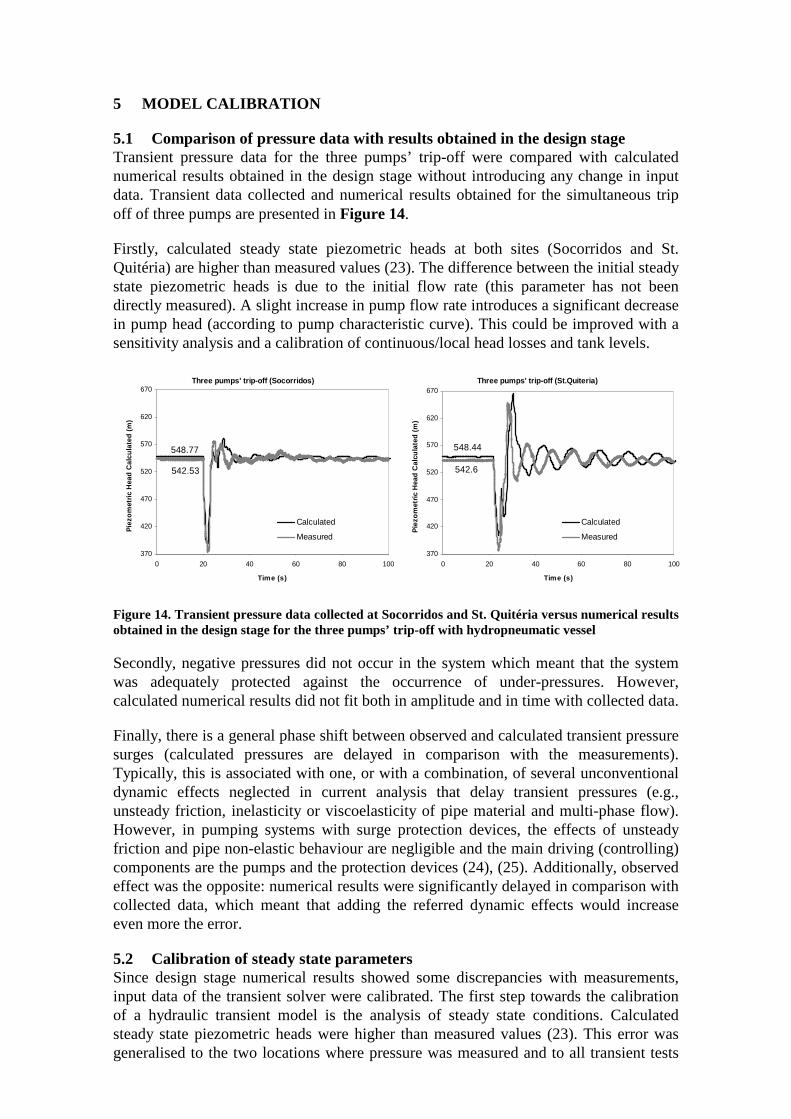
5.1 Comparison of pressure data with results obtained in the design stage Transient pressure data for the three pumps’ trip-off were compared with calculated numerical results obtained in the design stage without introducing any change in input data. Transient data collected and numerical results obtained for the simultaneous trip off of three pumps are presented in Figure 14.
Firstly, calculated steady state piezometric heads at both sites (Socorridos and St. Quitéria) are higher than measured values (23). The difference between the initial steady state piezometric heads is due to the initial flow rate (this parameter has not been directly measured). A slight increase in pump flow rate introduces a significant decrease in pump head (according to pump characteristic curve). This could be improved with a sensitivity analysis and a calibration of continuous/local head losses and tank levels.
Three pumps' trip-off (St.Quiteria)
548.44
542.6
370
420
470
520
570
620
670
0 20 40 60 80 100
Time (s)
Pie
zom
etric
Hea
d C
alcu
late
d (m
)
Calculated
Measured
Three pumps' trip-off (Socorridos)
548.77
542.53
370
420
470
520
570
620
670
0 20 40 60 80 100
Time (s)
Pie
zom
etric
Hea
d C
alcu
late
d (m
)
Calculated
Measured
Figure 14. Transient pressure data collected at Socorridos and St. Quitéria versus numerical results obtained in the design stage for the three pumps’ trip-off with hydropneumatic vessel
Secondly, negative pressures did not occur in the system which meant that the system was adequately protected against the occurrence of under-pressures. However, calculated numerical results did not fit both in amplitude and in time with collected data.
Finally, there is a general phase shift between observed and calculated transient pressure surges (calculated pressures are delayed in comparison with the measurements). Typically, this is associated with one, or with a combination, of several unconventional dynamic effects neglected in current analysis that delay transient pressures (e.g., unsteady friction, inelasticity or viscoelasticity of pipe material and multi-phase flow). However, in pumping systems with surge protection devices, the effects of unsteady friction and pipe non-elastic behaviour are negligible and the main driving (controlling) components are the pumps and the protection devices (24), (25). Additionally, observed effect was the opposite: numerical results were significantly delayed in comparison with collected data, which meant that adding the referred dynamic effects would increase even more the error.
5.2 Calibration of steady state parameters Since design stage numerical results showed some discrepancies with measurements, input data of the transient solver were calibrated. The first step towards the calibration of a hydraulic transient model is the analysis of steady state conditions. Calculated steady state piezometric heads were higher than measured values (23). This error was generalised to the two locations where pressure was measured and to all transient tests

that have been carried out. As referred in the previous section, this is due to the initial flow rate and pumping head. As pumping head depends on total head losses and on the levels of Socorridos and Covão storage tanks, a sensitivity analysis to these parameters has been carried out.
Total head losses – The diameter of the steel pipe from Socorridos to Covão is very high varying between 1,000 and 1,500 mm. Consequently total head losses in the pumping system for 1.97 m3/s are very low (approximately 2 m) in comparison with pumping head (470 m). Thus, the model results are not sensitive to this parameter.
Covão and Socorridos storage tanks’ levels - In the design stage, hydraulic transients were analysed for the worst operating scenario which corresponded to the three pumps shut-off and the maximum difference of elevation between the two storage tanks, that is Covão tank with the maximum water level (z=547.10) and Socorridos tank with the minimum water level (z=81.00). This corresponds to a total pump flow equal to a 1.93 m3/s and a pumping head equal to 467.8 m. In reality, during the data collection programme and typically when pumps in Socorridos are operating, storage tanks are in the opposite situation: Covão tank is almost empty (z=541.10) and Socorridos tank is full (z=85.60). This scenario corresponds to a total pump flow equal to 1.976 m3/s and a pumping head equal to 457.60 m. Thus, the model is very sensitive to this parameter, having the major part of the error been corrected with this calibration.
Accurate elevations of transducers - Piezometric heads have been calculated with the accurate elevations of transducers: at Socorridos pumping station z=89.00 (instead of 87.00) and z=323,00 (instead of 320,00). Additionally, the elevations in the model have been corrected accordingly.
In conclusion, by changing the level of the storage tanks and the elevation of transducers at Socorridos and St. Quiteria, the steady-state error has been corrected (see Figure 15).
Three pumps' trip-off (St.Quiteria)
542.64
542.6
370
420
470
520
570
620
670
0 20 40 60 80 100
Time (s)
Pie
zom
etric
Hea
d C
alcu
late
d (m
)
Calculated
Measured
Three pumps' trip-off (Socorridos)
543.12
542.53
370
420
470
520
570
620
670
0 20 40 60 80 100
Time (s)
Pie
zom
etric
Hea
d C
alcu
late
d (m
)
Calculated
Measured
Figure 15. Transient pressure data collected at Socorridos and St. Quitéria versus numerical results obtained after steady-state calibration for the three pumps’ trip-off with hydropneumatic vessel
5.3 Calibration of transient state parameters A general phase shift in observed and calculated transient pressure surges has been observed. Measured transient pressure wave propagates faster than numerically calculated one. This suggested that either the real wave speed is higher than estimated or the air vessel has a lower volume of air than numerically considered.

Pump simplifications - Initially, it was thought that part of the discrepancies were due to the pump dynamic behaviour as the following simplifications were done in the analysis: (i) The pump without check valve has been described by the turbo-pump characteristic
equations based on Sutter’s parameters experimentally determined for a set of specific speeds, Ns (i.e., Ns = 25, 147 and 261 rpm). In the current case, Ns = 12 rpm and Sutter’s parameters used were the corresponding to Ns = 25 rpm.
(ii) Each pump has got a special mechanism - a wheel break - that does not allow the inversion of the wheel rotation. This type of behaviour was not described by the model and, therefore, was simplified to a normal pump without check valve.
(iii) Total pump-motor inertia is a parameter given by manufacturers (330 kgm2). This has a direct effect in observed transient pressures.
(iv) A characteristic curve of a general butterfly valve was used to simulate the motorized valve located at the downstream of the pumps. This curve was supposed to be similar to the actual one, but still it was an approximation.
However, major discrepancies did not occur in the pumping station, but at St. Quitéria where the hidropneumatic vessel is located. Actually, minimum pressures at the pumping station fitted very well with collected data, which led the authors to believe that these were not the main cause of the error.
Hydropneumatic vessel volume and pipe branch – A sensitivity analysis has been carried out to the main parameters that describe the hydropneumatic vessel behaviour during hydraulic transients. The main parameters were: initial air volume (∀air), adiabatic coefficient (n) and local headlosses in and out of the vessel (Kdif). The basis in this analysis was the vessel with ∀air=1 m3, n=1.2 and Kdif=1/160, and one parameter was changed at a time. The following conclusions were drawn: (a) The lower the volume of air, the lower is the minimum pressure and the higher is
the maximum pressure (Figure 16a). Higher volumes of air are more efficient in water hammer protection. Higher air volumes introduce a higher delay and a higher damping of the transient pressure wave. The best fitting in the first seconds of the hydraulic transient (for t=20 until 26 s) is obtained for 0.5 m3 initial air volume, although measured value was 1 m3.
(b) The higher the adiabatic coefficient, the higher are extreme pressures (Figure 16b). This parameter does not affect the phase shift. Because the air volume is quite small (1 m3), this parameter hardly affects the extreme pressure values, although it strongly influences the delay and the damping of the pressure wave..
(c) The higher the headloss coefficient in the outflow is, the lower is the maximum pressure (Figure 16c). This parameter does not affect minimum pressures.
(d) The higher the headloss coefficient in the inflow is, the lower the minimum pressures are, and consequently the higher the maximum pressures (Figure 16d).
The best fitting is obtained for ∀air=1 m3, n=1.2 and Kdif=10/160 – cf. Figure 16(d).
Another parameter that significantly affects the transient response is the air vessel check valve (CV). The CV closes very fast but not instantaneously, and then it opens slightly allowing some reverse flow through it – cf. Figure 16(a). However, the model describes the check-valve as ideal (instantaneous closure, as the flow reverses). The dynamic behaviour of the check-valve is the most important source of uncertainty in the model as, until the CV closure, numerical results fit perfectly well with collected data. This can only be overcome by an extensive study of check valves.

(a)
320
370
420
470
520
570
620
670
720
20 25 30 35 40 45 50
Time (s)
Pie
zom
etric
hea
d (s
)
Vair = 0,5 m3Vair = 1,0 m3Vair = 1,5 m3Data
(b)
320
370
420
470
520
570
620
670
720
20 25 30 35 40 45 50
Time (s)
Pie
zom
etric
hea
d (s
)
n=1.0n=1.2n=1.4Data
(c)
320
370
420
470
520
570
620
670
720
770
820
20 25 30 35 40 45 50
Time (s)
Pie
zom
etric
hea
d (s
)
Kdif=1/1Kdif=1/80kdif=1/160Data
(d)
320
370
420
470
520
570
620
670
720
20 25 30 35 40 45 50
Time (s)
Pie
zom
etric
hea
d (s
)
kdif=1/160Kdif=10/160Kdif=20/160Kdif=80/160Data
Figure 16. Piezometric head at the upstream section of the hydroneumatic vessel for the three pumps’ trip-off. Sensitivity analysis to (a) initial air volume Vair, (b) adiabatic coefficient n, (c) local headlosses in the out-flow and (d) local headlosses in the inflow.
Wave speed – The effect of wave speed has been analysed by changing the Socorridos-St.Quiteria wave speed from 1150 m/s to 1250 and to 1400 m/s (i.e., increases of 9 and 23%). These changes affect very slightly transient pressures as presented in Figure 17 and does not solve the major phase shift observed.
Three pumps' trip-off (St.Quiteria)
370
420
470
520
570
620
670
20 25 30 35 40 45 50 55 60
Time (s)
Pie
zom
etric
Hea
d C
alcu
late
d (m
)
a=1150 m/sa=1250 m/sa=1400 m/sData
Three pumps' trip-off (Socorridos)
543.12
542.53
370
420
470
520
570
620
670
10 15 20 25 30 35 40 45 50
Time (s)
Pie
zom
etric
Hea
d C
alcu
late
d (m
)
a=1150 m/sa=1250 m/sa=1400 m/sData
Figure 17. Piezometric head at Socorridos and St. Quiteria for the three pumps’ trip-off for different wave speeds of Socorridos-St.Quiteria pipe – 1150, 1250 and 1400 m/s
CV closure

6 CONCLUSIONS
A hydraulic transient analysis of a hydropower system with multiple uses that has been converted into a pump-storage hydropower system by means of the construction of two storage-tanks and a pumping station, has been presented. Given the new operating conditions at the pumping station, a surge protection device was installed – a hydropneumatic vessel. Transient pressure data were collected for different operating conditions of the pumps. Numerical results obtained in the design stage were compared with collected transient pressure data. Negative pressures did not occur in the system which meant that the system was adequately protected against water hammer. However, calculated numerical results did not fit both in amplitude and in time with collected physical data. The main uncertainties associated with the numerical simulations of hydraulic transients was the storage tanks’ levels (that affected steady state pressures) and dynamic behaviour of the air vessel check-valve (that did not close instantaneously and allowed some reverse flow). The latter uncertainty can only be overcome by further analysis of the dynamic behaviour of “pseudo-ideal” check valves.
ACKNOWLEDGEMENTS
The authors wish to acknowledge the financial support of ENERGETUS and of Portuguese Research Foundation (FCT) through the projects POCTI/ECM/58375/2004 “Losses control and profit of available energy in water supply systems” and PTDC/ECM/65731/2006 “Energy and hydraulic efficiency e water supply systems”.
REFERENCES
(1) Almeida, A. B. and Koelle, E. (1992). Fluid Transients in Pipe Networks, Computational Mechanics Publications, Elsevier Applied Science, Southampton, UK.
(2) Chaudhry, M. H. (1987). Applied Hydraulic Transients, Litton Educational Publishing Inc., Van Nostrand Reinhold Co, New York, USA.
(3) Wylie, E. B. and Streeter, V. L. (1993). Fluid Transients in Systems, Prentice Hall, Englewood Cliffs, N.J..
(4) Covas, D. (2006). "Book Review "Pressure Wave Analysis of Transient Flow in Pipe Distribution Systems" Edited by Don J. Wood, Srinivasa Lingireddy and Paul F. Boulos, MWH Soft, Pasadena, CA, 2004, 213 pp (ISBN 0-9745689-2-9)." Urban Water Journal, 3(1), 51-52.
(5) Covas, D., Stoianov, I., Mano, J., Ramos, H., Graham, N., and Maksimovic, C. (2004). "The Dynamic Effect of Pipe-Wall Viscoelasticity in Hydraulic Transients. Part I - Experimental Analysis and Creep Characterization." Journal of Hydraulic Research, 42(5), 516-530.
(6) Covas, D., Stoianov, I., Mano, J., Ramos, H., Graham, N., and Maksimovic, C. (2005). "The Dynamic Effect of Pipe-Wall Viscoelasticity in Hydraulic Transients. Part II - Model Development, Calibration and Verification." Journal of Hydraulic Research, 43(1), 56-70.
(7) Ferry, J. D. (1970). Viscoelastic Properties of Polymers, Wiley-Interscience - John Wiley & Sons, New York, USA.
(8) Aklonis, J. J., MacKnight, W. J., and Shen, M. (1972). Introduction to Polymer Viscoelasticity, Wiley-IntersWiley-Interscience - John Wiley & Sons, Inc, New York, USA.
(9) Almeida, A. B. and Covas, D. (2004). "Socorridos Pumping Station and Storage Tank. Water hammer analysis - Part 1." December/2004, Instituto Superior Técnico, Lisboa (in Portuguese).
(10) Almeida, A. B. and Covas, D. (2005). "Socorridos Pumping Station and Storage Tank. Water hammer analysis - Final report - Part 3." June/2005, Instituto Superior Técnico, Lisboa (in Portuguese).

(11) Almeida, A. B. and Covas, D. (2005). "Socorridos Pumping Station and Storage Tank. Water hammer analysis - Part 2." January/2005, Instituto Superior Técnico, Lisboa (in Portuguese).
(12) Ramos, H. (1995). "Simulation and Control of Hydrotransients at Small Hydroelectric Power Plants." PhD, Instituto Superior Técnico, Technical University of Lisbon, Portugal.
(13) Ramos, H. and Covas, D. (2006). "Water pipe system response under dynamic effects." Journal of Water Supply: Research and Technology - Aqua, 55, 269-282.
(14) Ramos, H., Covas, D., and Almeida, A. B. (2005). "Unconventional dynamic effects in plastic water pipe systems." XXXI IAHR Congress, Seoull, Korea, 12-18 Sept.2005.
(15) Trikha, A. K. (1975). "An efficient method for simulating frequency-dependent friction in transient liquid flow." Journal of Fluids Engineering, Trans. ASME, 97(1), 97-105.
(16) Brunone, B., Golia, U. M., and Greco, M. (1995). "Effects of Two-Dimensionality on Pipe Transients Modelling." Journal of Hydraulic Engineering, ASCE, 121(12), 906-912.
(17) Zielke, W. (1968). "Frequency-dependent friction in transient pipe flow." Journal of Basic Engineering, Trans. ASME, Series D, 90(1), 109-115.
(18) Vardy, A. E. and Brown, J. (1996). "On turbulent, unsteady, smooth-pipe friction." Proceedings of the 7th International Conference on Pressure Surges and Fluid Transients in Pipelines and Open Channels, BHR Group Ltd., Harrogate, England, 289-311.
(19) Silva-Araya, W. F. and Chaudhry, M. H. (1997). "Computation of energy dissipation in transient flow." Journal of Hydraulic Engineering, ASCE, 123(2), 108-115.
(20) Eichinger, P. and Lein, G. (1992). "The influence of friction on unsteady pipe flow." Proceedings of the International Conference on Unsteady Flow and Fluid Transients, Bettess & Watts, Balkema, Rotterdam, 41-50.
(21) Bergant, A., Simpson, A. R., and Vitkovsky, J. P. (1999). "A Review of Unsteady Friction Models Transient Pipe Flow." Proceedings of 9th International Meeting on the Behaviour of Hydraulic Machinery under Steady Oscillatory Conditions, IAHR, Brno, Czech Republic.
(22) Vardy, A. E., Hwang, K. L., and Brown, J. (1993). "A weighting function model of transient turbulent pipe friction." Journal of Hydraulic Research, 31(4), 533-548.
(23) Covas, D. I. C., Ramos, H. M., and Almeida, A. B. (2007). "Hydraulic transient analysis: from the design stage to real life testing." Water Management Challenges in Global Change. CCWI2007 and SUWM2007 Conference. De Monfort University, Leicester, UK, 3-5 September 2007.
(24) Covas, D. (2003). "Inverse Transient Analysis for Leak Detection and Calibration of Water Pipe Systems - Modelling Special Dynamic Effects." PhD, Imperial College of Science, Technology and Medicine, University of London, UK.
(25) Covas, D., Stoianov, I., Ramos, H., Graham, N., and Maksimovic, C. (2003). "The Dissipation of Pressure Surges in Water Pipeline Systems." Pumps, Electromechanical Devices and Systems Applied to Urban Management. Volume 2., The Netherlands, Balkema Publishers, 711-719.