Embed Size (px)
Citation preview
© 2020 Demountable Concepts, Inc. 0484-A
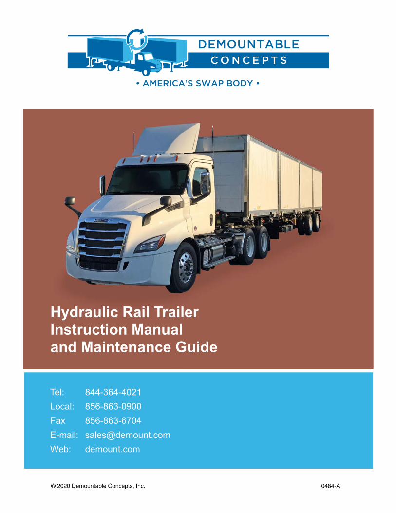
Hydraulic Rail Trailer Instruction Manual and Maintenance Guide
Tel: 844-364-4021 Local: 856-863-0900Fax 856-863-6704 E-mail: [email protected] Web: demount.com

Hydraulic Rail Trailer Instruction Manual and Maintenance Guide demount.com | 844-364-4021
2
Demounting Bodies - Section 1
Orientation - System Components Page 3
Warnings Page 4
Prepare to Demount, Unlock Body Page 5
Lift Trailer and Disconnect Light Plugs Page 6
Lower Center Stops and Set Legs Page 7
Lower Trailer Page 8
Pull Out from Body Page 9
Mounting Bodies - Section 2
Preparing and Backing Under Page 9
Lift Trailer Page 10
Store the Legs and Lock Bodies Page 11
Connect Light Plugs and Pre-Trip Page 12
Additional Features - Section 3
Additional Trailer Features Page 13
Maintenance - Section 4
Trailer, Tractor Trailer, and Hydraulic Landing Gear Checklist Page 14
Parts List Page 15
Diagrams - Section 5
Electrical Schematic - Container Chassis 4 Body Van Lock System Page 17
4-Way Plug and Receptacle Wiring Trailer Harness Page 18
Check for Missing or Damaged Components Page 19
Trouble Shooting - Section 6
Trouble Shooting Page 20
Trouble Sooting Hydraulic Legs Page 25
TABLE OF CONTENTS
Hydraulic Rail Trailer Instruction Manual and Maintenance Guide demount.com | 844-364-4021
3
SECTION 1 DEMOUNTING BODIES
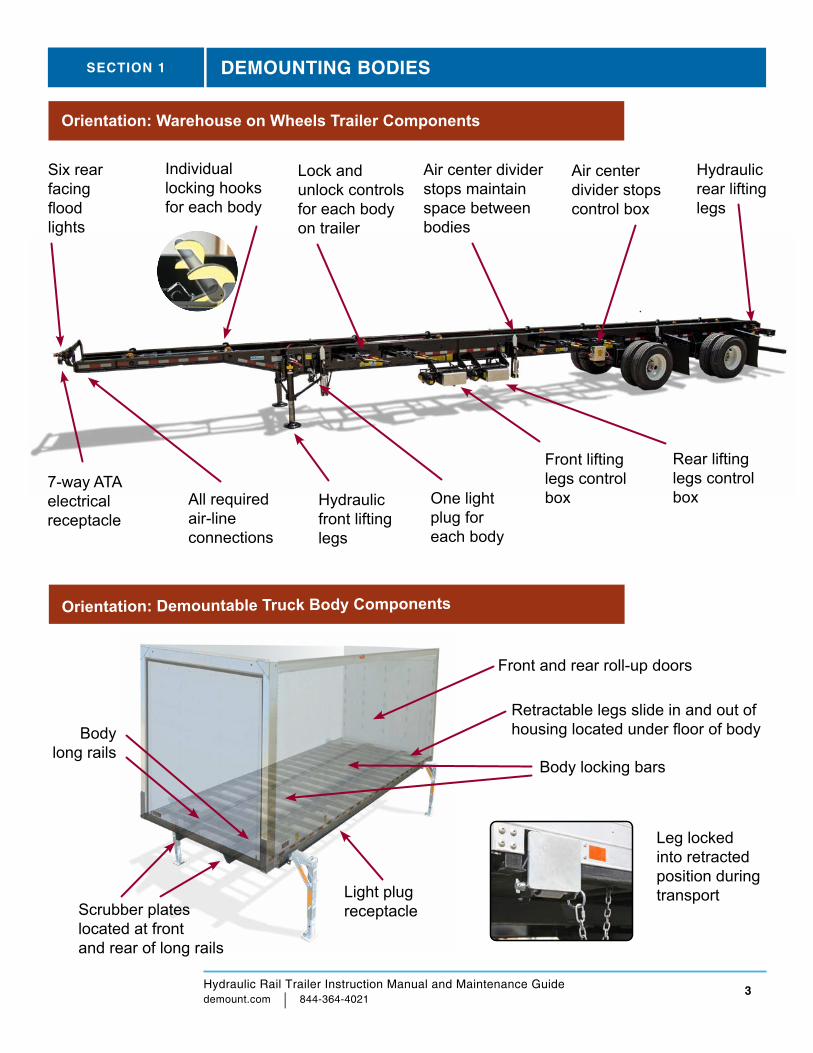
Orientation: Warehouse on Wheels Trailer Components
Retractable legs slide in and out ofhousing located under floor of body
Leg locked into retracted position during transport
Body long rails
Front and rear roll-up doors
Light plug receptacleScrubber plates
located at front and rear of long rails
Orientation: Demountable Truck Body Components
7-way ATAelectrical receptacle
All required air-line connections
Individual locking hooks for each body
Air center divider stops maintain space between bodies
Front lifting legs control box
Six rear facing flood lights
Rear lifting legs control box
Air center divider stops control box
Hydraulic front lifting legs
Hydraulic rear lifting legs
Lock and unlock controls for each body on trailer
One light plug for each body
Body locking bars
Hydraulic Rail Trailer Instruction Manual and Maintenance Guide demount.com | 844-364-4021
4
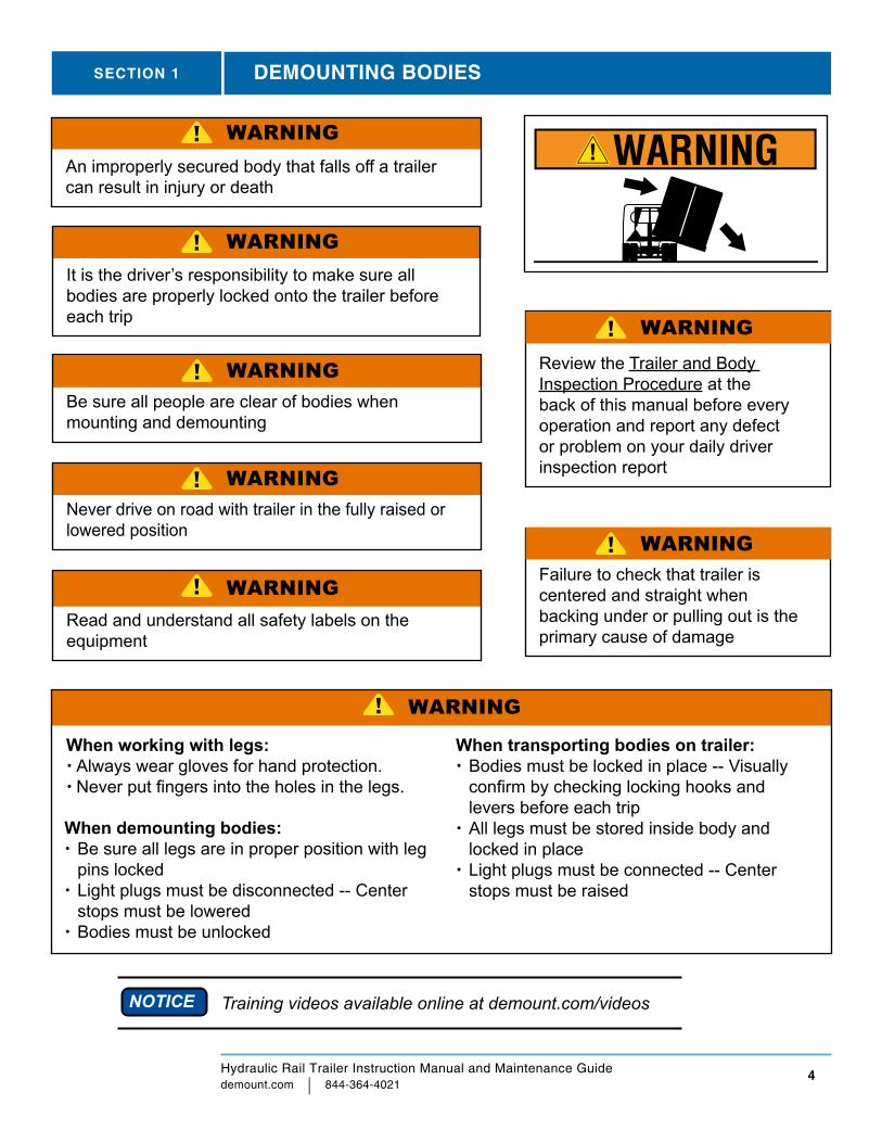
WARNINGFailure to check that trailer is centered and straight when backing under or pulling out is the primary cause of damage
Training videos available online at demount.com/videos
SECTION 1
When demounting bodies:Be sure all legs are in proper position with leg pins lockedLight plugs must be disconnected -- Center stops must be loweredBodies must be unlocked
An improperly secured body that falls off a trailer can result in injury or death
It is the driver’s responsibility to make sure all bodies are properly locked onto the trailer before each trip
Be sure all people are clear of bodies when mounting and demounting
Never drive on road with trailer in the fully raised or lowered position
Review the Trailer and Body Inspection Procedure at the back of this manual before every operation and report any defect or problem on your daily driver inspection report
Read and understand all safety labels on the equipment
When working with legs: Always wear gloves for hand protection. Never put fingers into the holes in the legs.
NOTICE
WARNING
WARNING
WARNING
WARNING
WARNING
WARNING
When transporting bodies on trailer:Bodies must be locked in place -- Visually confirm by checking locking hooks and levers before each tripAll legs must be stored inside body and locked in placeLight plugs must be connected -- Center stops must be raised
WARNING
DEMOUNTING BODIES
Hydraulic Rail Trailer Instruction Manual and Maintenance Guide demount.com | 844-364-4021
5
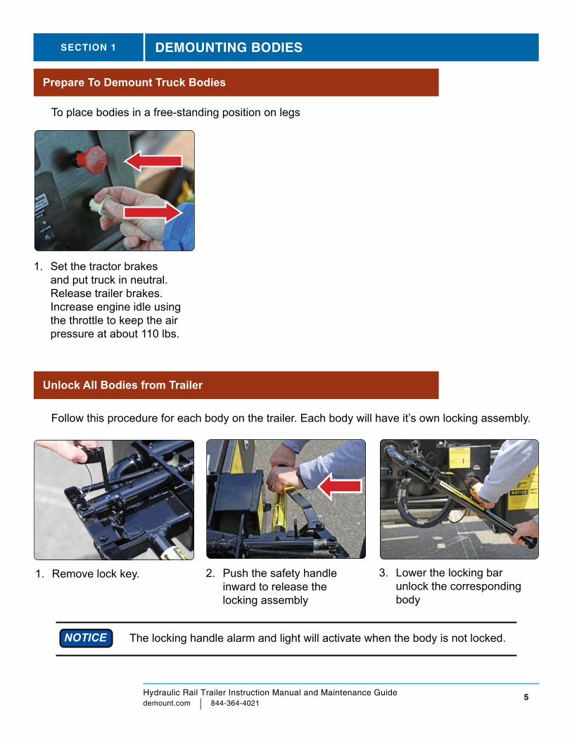
To place bodies in a free-standing position on legs
Unlock All Bodies from Trailer
Prepare To Demount Truck Bodies
1. Remove lock key. 2. Push the safety handle inward to release the locking assembly
3. Lower the locking bar unlock the corresponding body
The locking handle alarm and light will activate when the body is not locked.NOTICE
SECTION 1 DEMOUNTING BODIES
1. Set the tractor brakes and put truck in neutral. Release trailer brakes. Increase engine idle using the throttle to keep the air pressure at about 110 lbs.
Follow this procedure for each body on the trailer. Each body will have it’s own locking assembly.
Hydraulic Rail Trailer Instruction Manual and Maintenance Guide demount.com | 844-364-4021
6
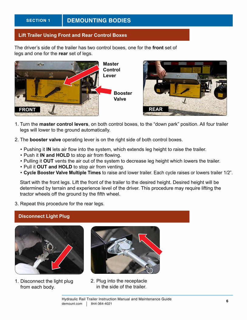
1. Disconnect the light plug from each body.
2. Plug into the receptacle in the side of the trailer.
Disconnect Light Plug
Lift Trailer Using Front and Rear Control Boxes
SECTION 1 DEMOUNTING BODIES
The driver’s side of the trailer has two control boxes, one for the front set of legs and one for the rear set of legs.
FRONT REAR
Master Control Lever
Booster Valve
1. Turn the master control levers, on both control boxes, to the “down park” position. All four trailer legs will lower to the ground automatically.
2. The booster valve operating lever is on the right side of both control boxes.
• Pushing it IN lets air flow into the system, which extends leg height to raise the trailer. • Push it IN and HOLD to stop air from flowing. • Pulling it OUT vents the air out of the system to decrease leg height which lowers the trailer. • Pull it OUT and HOLD to stop air from venting. • Cycle Booster Valve Multiple Times to raise and lower trailer. Each cycle raises or lowers trailer 1/2”.
Start with the front legs. Lift the front of the trailer to the desired height. Desired height will be determined by terrain and experience level of the driver. This procedure may require lifting the tractor wheels off the ground by the fifth wheel.
3. Repeat this procedure for the rear legs.
Hydraulic Rail Trailer Instruction Manual and Maintenance Guide demount.com | 844-364-4021
7
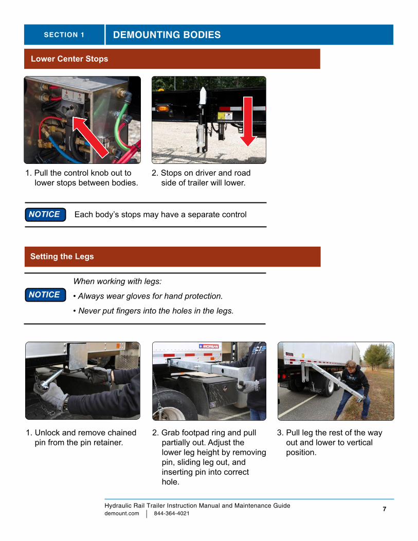
1. Pull the control knob out to lower stops between bodies.
1. Unlock and remove chained pin from the pin retainer.
2. Grab footpad ring and pull partially out. Adjust the lower leg height by removing pin, sliding leg out, and inserting pin into correct hole.
3. Pull leg the rest of the way out and lower to vertical position.
Lower Center Stops
Setting the Legs
SECTION 1 DEMOUNTING BODIES
2. Stops on driver and road side of trailer will lower.
NOTICE Each body’s stops may have a separate control
When working with legs:
• Always wear gloves for hand protection.
• Never put fingers into the holes in the legs.
NOTICE
Hydraulic Rail Trailer Instruction Manual and Maintenance Guide demount.com | 844-364-4021
8
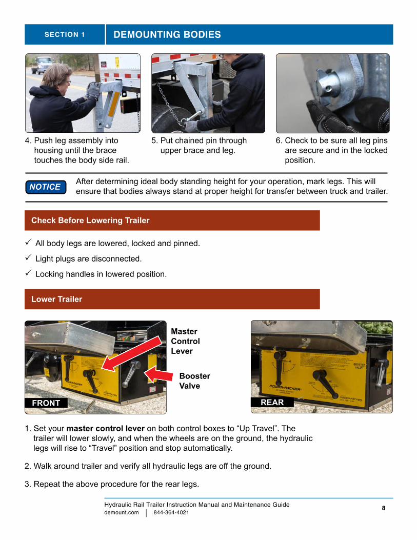
4. Push leg assembly into housing until the brace touches the body side rail.
5. Put chained pin through upper brace and leg.
6. Check to be sure all leg pins are secure and in the locked position.
After determining ideal body standing height for your operation, mark legs. This will ensure that bodies always stand at proper height for transfer between truck and trailer.NOTICE
All body legs are lowered, locked and pinned.
Light plugs are disconnected.
Locking handles in lowered position.
Check Before Lowering Trailer
Lower Trailer
SECTION 1 DEMOUNTING BODIES
1. Set your master control lever on both control boxes to “Up Travel”. The trailer will lower slowly, and when the wheels are on the ground, the hydraulic legs will rise to “Travel” position and stop automatically.
2. Walk around trailer and verify all hydraulic legs are off the ground.
3. Repeat the above procedure for the rear legs.
FRONT REAR
Master Control Lever
Booster Valve

Hydraulic Rail Trailer Instruction Manual and Maintenance Guide demount.com | 844-364-4021
9
Before You Back Up
1. Be sure locking hooks are in the down position
Backing Under Bodies
3. Turn on flood lights, the switch is located near glad-hand connections.
SECTION 1 DEMOUNTING BODIES
1. Back straight under bodies. Get out and check alignment 2-3 times before backing all the way underneath.
2. Reposition trailer as needed. Do not over steer. Front stops must contact body.
3. Set tractor and trailer brakes.
Pulling Out From Body
1. Make sure there is clearance the entire length of trailer, between the bottom of bodies and top of trailer frame, before pulling trailer out from under the body.
2. Release parking brake.
3. Pull trailer forward slowly.
4. Be sure to pull out straight until entire trailer is out from under the bodies.
SECTION 2 MOUNTING BODIES
2. Be sure the center stops are lowered.
Hydraulic Rail Trailer Instruction Manual and Maintenance Guide demount.com | 844-364-4021
10
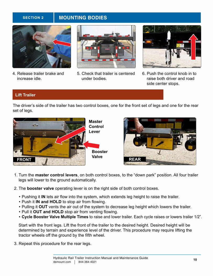
4. Release trailer brake and increase idle.
5. Check that trailer is centered under bodies.
6. Push the control knob in to raise both driver and road side center stops.
Lift Trailer
SECTION 2 MOUNTING BODIES
The driver’s side of the trailer has two control boxes, one for the front set of legs and one for the rear set of legs.
FRONT REAR
Master Control Lever
Booster Valve
1. Turn the master control levers, on both control boxes, to the “down park” position. All four trailer legs will lower to the ground automatically.
2. The booster valve operating lever is on the right side of both control boxes.
• Pushing it IN lets air flow into the system, which extends leg height to raise the trailer. • Push it IN and HOLD to stop air from flowing. • Pulling it OUT vents the air out of the system to decrease leg height which lowers the trailer. • Pull it OUT and HOLD stop air from venting flowing. • Cycle Booster Valve Multiple Times to raise and lower trailer. Each cycle raises or lowers trailer 1/2”.
Start with the front legs. Lift the front of the trailer to the desired height. Desired height will be determined by terrain and experience level of the driver. This procedure may require lifting the tractor wheels off the ground by the fifth wheel.
3. Repeat this procedure for the rear legs.

Hydraulic Rail Trailer Instruction Manual and Maintenance Guide demount.com | 844-364-4021
11
1. Unlock and remove the chained pin at the upper leg stabilizing brace.
2. Lift entire leg to horizontal position and slide partially into the leg housing.
3. Remove lower leg pin, slide in inner leg and insert pin through inner and outer leg at last hole.
4. Push leg completely into housing – Keep fingers clear.
5. Insert pin through leg retainers on body and loop on foot pad.
6. Flip lock on pin into place. Check to be sure all legs are locked into place.
Storing the Legs
SECTION 2 MOUNTING BODIES
Lock Bodies
1. For each body lift the corresponding locking handle up.
2. Making sure the safety pin/ handle goes into place.
3. Insert the locking key in the safety pin.
Hydraulic Rail Trailer Instruction Manual and Maintenance Guide demount.com | 844-364-4021
12
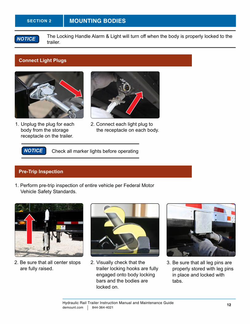
Connect Light Plugs
Pre-Trip Inspection
1. Perform pre-trip inspection of entire vehicle per Federal Motor Vehicle Safety Standards.
The Locking Handle Alarm & Light will turn off when the body is properly locked to the trailer.NOTICE
2. Connect each light plug to the receptacle on each body.
SECTION 2 MOUNTING BODIES
Check all marker lights before operating NOTICE
1. Unplug the plug for each body from the storage receptacle on the trailer.
2. Be sure that all center stops are fully raised.
2. Visually check that the trailer locking hooks are fully engaged onto body locking bars and the bodies are locked on.
3. Be sure that all leg pins are properly stored with leg pins in place and locked with tabs.

Hydraulic Rail Trailer Instruction Manual and Maintenance Guide demount.com | 844-364-4021
13
SECTION 2 MOUNTING BODIES
4. Be sure that all light plugs are plugged into each body’s receptacle.
5. Be sure the locking pins are fully inserted and locking handle and alarm switch are intact and secure.
Pre-Trip, Continued
6. The unit is now ready to be driven.
SECTION 3 ADDITIONAL TRAILER FEATURES
System Operation:
Suspension Dump: Lift knob on RA030 valve to dump all suspension ride bags. Push Down to fill.
Lift Axle Down: With the red manual control knob up and electric power off, the lift ride bags will fill to the system pressure.
Lift Axle Up: Supply 12 volt DC power to the solenoid (the red knob must be up) OR manually push the control knob down and twist to lock.
Lift Axle Service BrakeLine In
Air Tank SupplyLine In
Lift Axle Service BrakeLine Out
Lift Axle Ride BagSupplyLift Axle Lift BagSupply
Solenoid Wire
Air Supply from Height Control
Fixed Axle Suspension Supply
(A)(C )
(B)
RA013S Suspension Control - (S/N - 2311100)

Hydraulic Rail Trailer Instruction Manual and Maintenance Guide demount.com | 844-364-4021
14
Tractor Trailer Check List
INSPECT: Inspected OK
Needs Repair
Comments
Front Locking Bar Assembly □ □Rear Locking Bar Assembly □ □Measurements of front hooks □ □Measurements of rear hooks □ □ Adjust front and rear hooks as required □ □
Demountable Trailer Maintenance Check List
Trailer maintenance to be done with chassis only with no bodies attached.
NOTICE Checklist is in addition to standard trailer maintenance procedures.NOTICE
Locking Hooks
□ Check measurements of front hooks
□ Check measurements of rear hooks
□ Adjust front and rear hooks as required
□ Grease all locking shafts on the trailer
□ Grease locking lever at locking pin
□ Check that locking lever is in good working order
Center Stops
□ Check that center stops work smoothly
□ Grease center stops with spray lithium grease
□ Check center stop pins (if applicable)
Electrical
□ Check all trailer lights
□ Check light plug front and rear
□ Clean front trailer 7-way connector
SECTION 4 MAINTENANCE

Hydraulic Rail Trailer Instruction Manual and Maintenance Guide demount.com | 844-364-4021
15
Hydraulic Landing Gear Check List
INSPECT: Hydraulic Landing Gear (if applicable)
Inspected OK
Needs Repair
Comments
Check Oil Level □ □Inspect fully extend legs □ □Check all hydraulic lines and fittings for leaks □ □Check for loose bolts and nuts □ □
Check that center stops work smoothly □ □Check center stop pins □ □Check all trailer lights □ □Check light plug front and rear □ □Check condition of air bags □ □Check condition of shock absorbers □ □Check all air lines and fittings for leaks or wear □ □Check for loose nuts and bolts □ □
Parts
Part Number DescriptionDC-1253 LIGHT PLUG 4 WAY WITH CABLE PROTECTOR
DC-1253-W10 LIGHT PLUG 4 WAY WITH 10’ WIRE
DCI-DL-235 SAFETY LOCKOUT HANDLE WITH GRIP AND HARDWARE
DCI-DL-234 LOCKING SYSTEM ASSY. SPRING
DCI-DL-233 LOCKING SYSTEM ASSY. PIN SS
DCI-DL-236A SAFETY LOCKOUT KEY WITH CABLE
SECTION 4 MAINTENANCE
Hydraulic Rail Trailer Instruction Manual and Maintenance Guide demount.com | 844-364-4021
16
Purchase parts online at dcixpress.com or by phone 844-364-4021
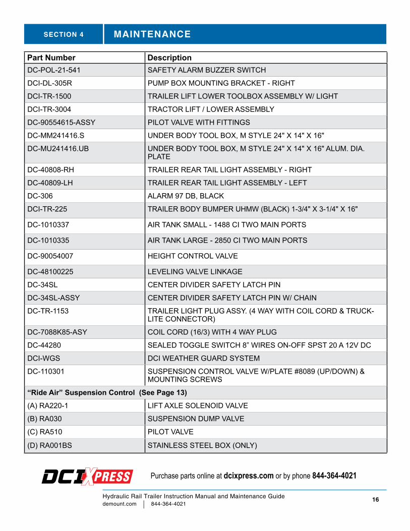
Part Number DescriptionDC-POL-21-541 SAFETY ALARM BUZZER SWITCH
DCI-DL-305R PUMP BOX MOUNTING BRACKET - RIGHT
DCI-TR-1500 TRAILER LIFT LOWER TOOLBOX ASSEMBLY W/ LIGHT
DCI-TR-3004 TRACTOR LIFT / LOWER ASSEMBLY
DC-90554615-ASSY PILOT VALVE WITH FITTINGS
DC-MM241416.S UNDER BODY TOOL BOX, M STYLE 24" X 14" X 16"
DC-MU241416.UB UNDER BODY TOOL BOX, M STYLE 24" X 14" X 16" ALUM. DIA. PLATE
DC-40808-RH TRAILER REAR TAIL LIGHT ASSEMBLY - RIGHT
DC-40809-LH TRAILER REAR TAIL LIGHT ASSEMBLY - LEFT
DC-306 ALARM 97 DB, BLACK
DCI-TR-225 TRAILER BODY BUMPER UHMW (BLACK) 1-3/4" X 3-1/4" X 16"
DC-1010337 AIR TANK SMALL - 1488 CI TWO MAIN PORTS
DC-1010335 AIR TANK LARGE - 2850 CI TWO MAIN PORTS
DC-90054007 HEIGHT CONTROL VALVE
DC-48100225 LEVELING VALVE LINKAGE
DC-34SL CENTER DIVIDER SAFETY LATCH PIN
DC-34SL-ASSY CENTER DIVIDER SAFETY LATCH PIN W/ CHAIN
DC-TR-1153 TRAILER LIGHT PLUG ASSY. (4 WAY WITH COIL CORD & TRUCK-LITE CONNECTOR)
DC-7088K85-ASY COIL CORD (16/3) WITH 4 WAY PLUG
DC-44280 SEALED TOGGLE SWITCH 8” WIRES ON-OFF SPST 20 A 12V DC
DCI-WGS DCI WEATHER GUARD SYSTEM
DC-110301 SUSPENSION CONTROL VALVE W/PLATE #8089 (UP/DOWN) & MOUNTING SCREWS
“Ride Air” Suspension Control (See Page 13)(A) RA220-1 LIFT AXLE SOLENOID VALVE
(B) RA030 SUSPENSION DUMP VALVE
(C) RA510 PILOT VALVE
(D) RA001BS STAINLESS STEEL BOX (ONLY)
SECTION 4 MAINTENANCE
Hydraulic Rail Trailer Instruction Manual and Maintenance Guide demount.com | 844-364-4021
17
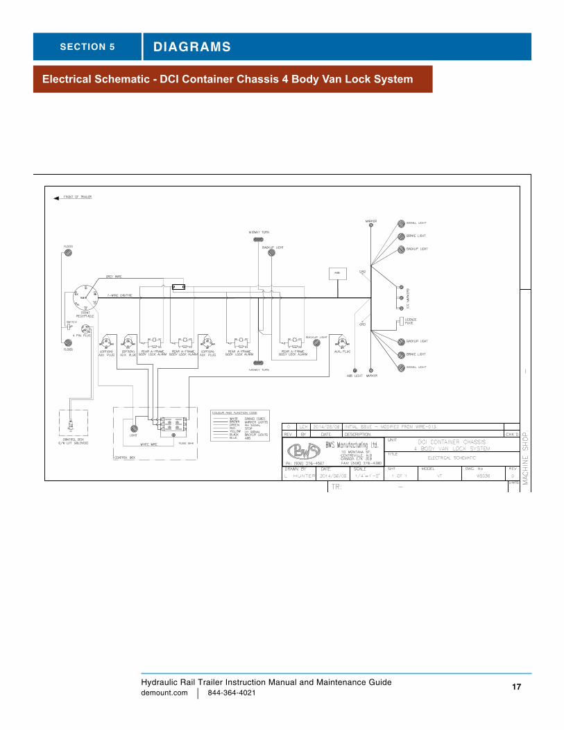
Electrical Schematic - DCI Container Chassis 4 Body Van Lock System
SECTION 5 DIAGRAMS
Hydraulic Rail Trailer Instruction Manual and Maintenance Guide demount.com | 844-364-4021
18
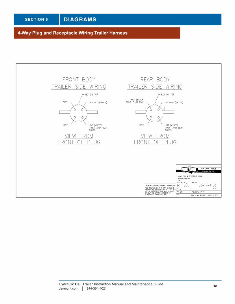
4-Way Plug and Receptacle Wiring Trailer Harness
SECTION 5 DIAGRAMS
Hydraulic Rail Trailer Instruction Manual and Maintenance Guide demount.com | 844-364-4021
19
DRAWNCHECKED
SHEET 1 OF 1
Locking LeverN/A
N/A x N/AN/A
jolynyk
4/3/2017
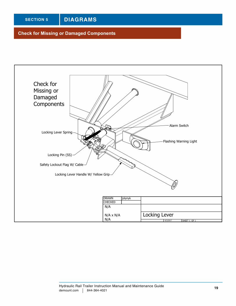
Flashing Warning Light
Locking Lever Handle W/ Yellow Grip
Locking Lever Spring
Safety Lockout Flag W/ Cable
Locking Pin (SS)
Alarm Switch
Check for Missing or Damaged Components
SECTION 5 DIAGRAMS
Check for Missing or Damaged Components
Hydraulic Rail Trailer Instruction Manual and Maintenance Guide demount.com | 844-364-4021
20
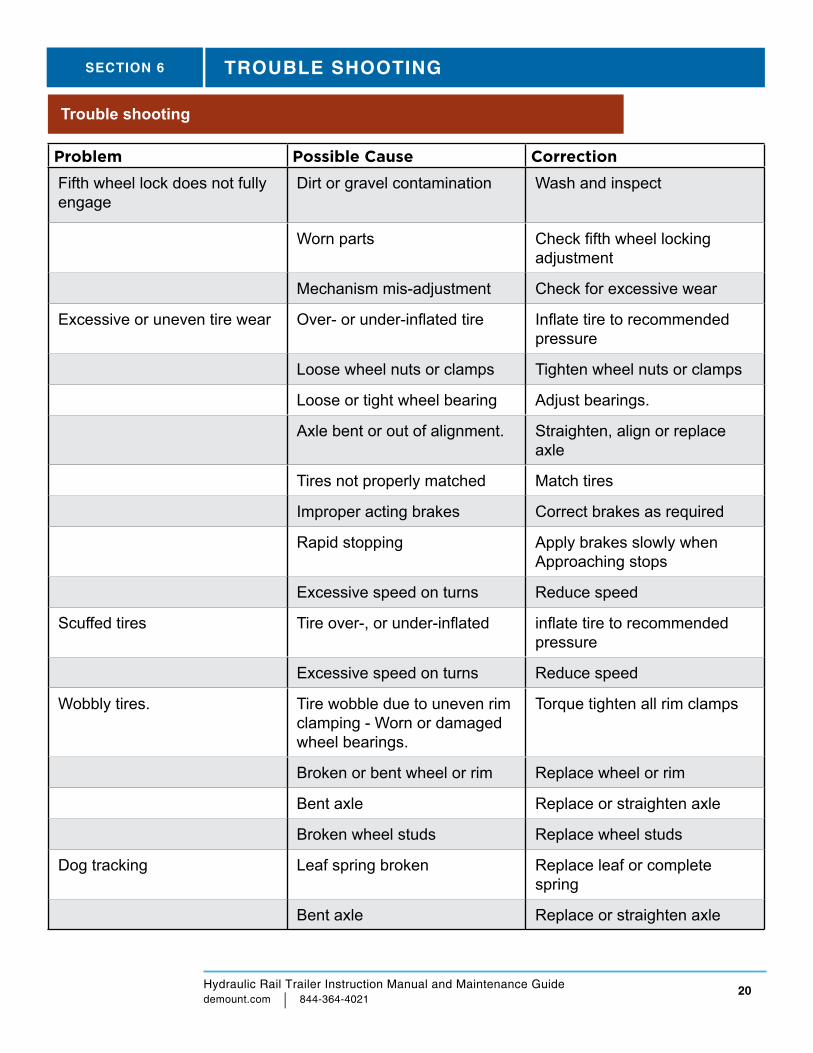
Trouble shooting
Problem Possible Cause Correction
Fifth wheel lock does not fully engage
Dirt or gravel contamination Wash and inspect
Worn parts Check fifth wheel locking adjustment
Mechanism mis-adjustment Check for excessive wear
Excessive or uneven tire wear Over- or under-inflated tire Inflate tire to recommended pressure
Loose wheel nuts or clamps Tighten wheel nuts or clamps
Loose or tight wheel bearing Adjust bearings.
Axle bent or out of alignment. Straighten, align or replace axle
Tires not properly matched Match tires
Improper acting brakes Correct brakes as required
Rapid stopping Apply brakes slowly when Approaching stops
Excessive speed on turns Reduce speed
Scuffed tires Tire over-, or under-inflated inflate tire to recommended pressure
Excessive speed on turns Reduce speed
Wobbly tires. Tire wobble due to uneven rim clamping - Worn or damaged wheel bearings.
Torque tighten all rim clamps
Broken or bent wheel or rim Replace wheel or rim
Bent axle Replace or straighten axle
Broken wheel studs Replace wheel studs
Dog tracking Leaf spring broken Replace leaf or complete spring
Bent axle Replace or straighten axle
SECTION 6 TROUBLE SHOOTING

Hydraulic Rail Trailer Instruction Manual and Maintenance Guide demount.com | 844-364-4021
21
Problem Possible Cause Correction
Frame or suspension (axles) out of alignment
Straighten frame or align axles
Worn or damaged torque arms or bushings
Check or replace
Loss of tire air pressure Puncture in tire Repair or replace tire
Faulty valve or valve core Replace valve assembly or core
Wheel or rim damage Replace wheel or rim
Brakes do not apply evenly. Brake valve(s) not operating correctly
Check brake adjustment and related items
Loading of trailer not proportional
Redistribute load
Brakes do not release. Brake shoe bound up at anchor pins
Lubricate brake operating parts
Brake hoses restricted Replace hoses
Brake out of alignment Adjust brakes
Damaged brake assembly Replace damaged parts
Contaminated air valves Clean or replace
No brakes or insufficient brakes
Source of air supply shut off at tractor
Open cutout cocks at rear of tractor cab or push control valve “IN”
Disconnected or not properly coupled glad hands
Connect or properly couple glad hands
Low brake line pressure Check air pressure gauge on tractor or for inoperative compressor
Brake pads worn or glazed Replace pads
Reservoir drain valve open Close drain valve
SECTION 6 TROUBLE SHOOTING
Hydraulic Rail Trailer Instruction Manual and Maintenance Guide demount.com | 844-364-4021
22
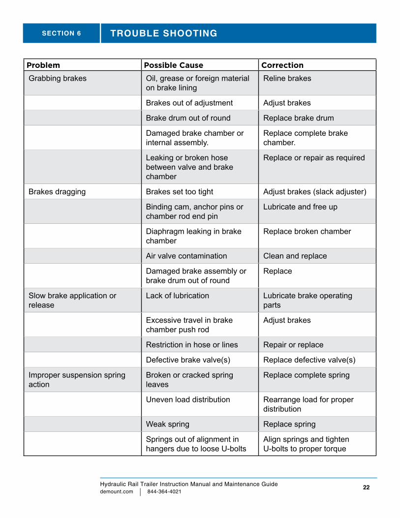
Problem Possible Cause Correction
Grabbing brakes Oil, grease or foreign material on brake lining
Reline brakes
Brakes out of adjustment Adjust brakes
Brake drum out of round Replace brake drum
Damaged brake chamber or internal assembly.
Replace complete brake chamber.
Leaking or broken hose between valve and brake chamber
Replace or repair as required
Brakes dragging Brakes set too tight Adjust brakes (slack adjuster)
Binding cam, anchor pins or chamber rod end pin
Lubricate and free up
Diaphragm leaking in brake chamber
Replace broken chamber
Air valve contamination Clean and replace
Damaged brake assembly or brake drum out of round
Replace
Slow brake application or release
Lack of lubrication Lubricate brake operating parts
Excessive travel in brake chamber push rod
Adjust brakes
Restriction in hose or lines Repair or replace
Defective brake valve(s) Replace defective valve(s)
Improper suspension spring action
Broken or cracked spring leaves
Replace complete spring
Uneven load distribution Rearrange load for proper distribution
Weak spring Replace spring
Springs out of alignment in hangers due to loose U-bolts
Align springs and tighten U-bolts to proper torque
SECTION 6 TROUBLE SHOOTING
Hydraulic Rail Trailer Instruction Manual and Maintenance Guide demount.com | 844-364-4021
23
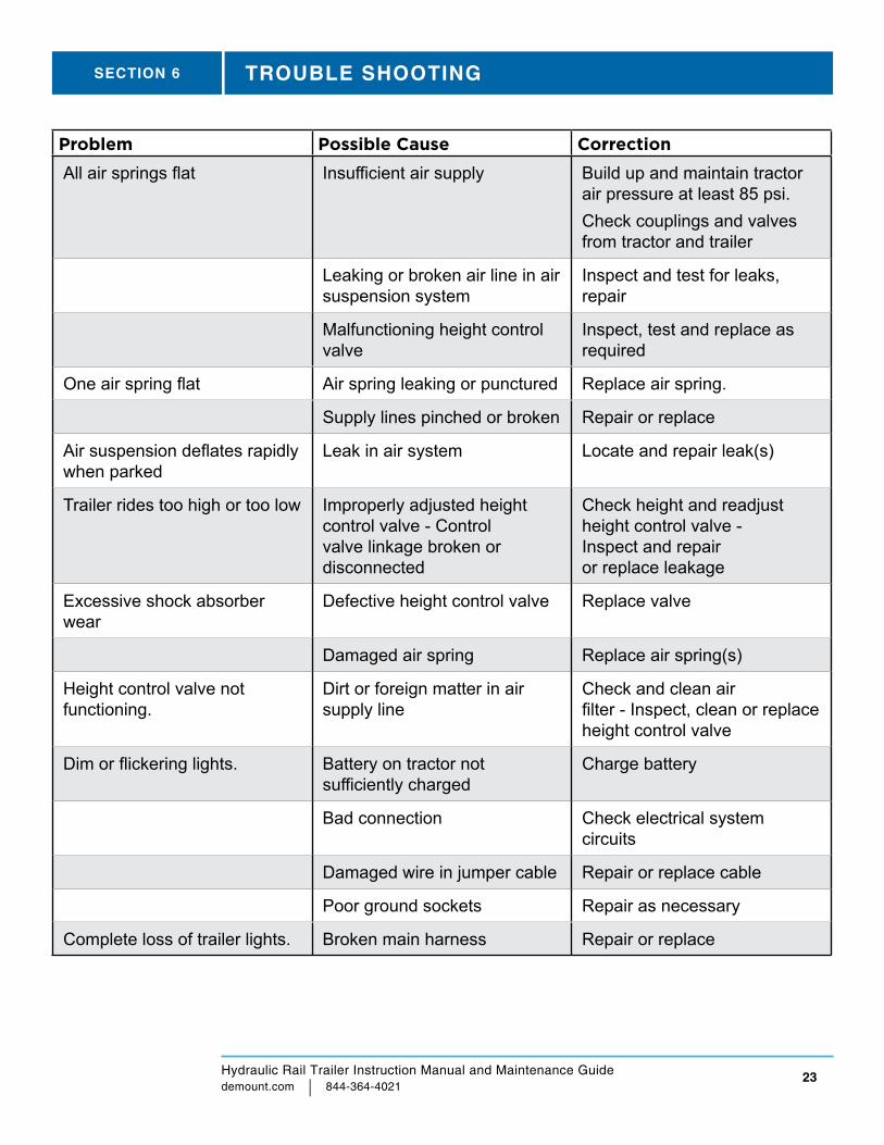
Problem Possible Cause Correction
All air springs flat Insufficient air supply Build up and maintain tractor air pressure at least 85 psi.Check couplings and valves from tractor and trailer
Leaking or broken air line in air suspension system
Inspect and test for leaks, repair
Malfunctioning height control valve
Inspect, test and replace as required
One air spring flat Air spring leaking or punctured Replace air spring.
Supply lines pinched or broken Repair or replace
Air suspension deflates rapidly when parked
Leak in air system Locate and repair leak(s)
Trailer rides too high or too low Improperly adjusted height control valve - Control valve linkage broken or disconnected
Check height and readjust height control valve - Inspect and repair or replace leakage
Excessive shock absorber wear
Defective height control valve Replace valve
Damaged air spring Replace air spring(s)
Height control valve not functioning.
Dirt or foreign matter in air supply line
Check and clean air filter - Inspect, clean or replace height control valve
Dim or flickering lights. Battery on tractor not sufficiently charged
Charge battery
Bad connection Check electrical system circuits
Damaged wire in jumper cable Repair or replace cable
Poor ground sockets Repair as necessary
Complete loss of trailer lights. Broken main harness Repair or replace
SECTION 6 TROUBLE SHOOTING
Hydraulic Rail Trailer Instruction Manual and Maintenance Guide demount.com | 844-364-4021
24
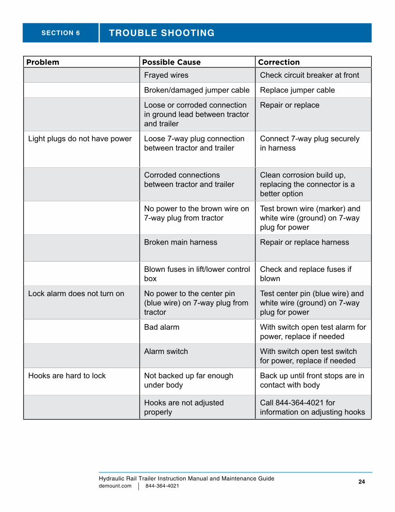
Problem Possible Cause Correction
Frayed wires Check circuit breaker at front
Broken/damaged jumper cable Replace jumper cable
Loose or corroded connection in ground lead between tractor and trailer
Repair or replace
Light plugs do not have power Loose 7-way plug connection between tractor and trailer
Connect 7-way plug securely in harness
Corroded connections between tractor and trailer
Clean corrosion build up, replacing the connector is a better option
No power to the brown wire on 7-way plug from tractor
Test brown wire (marker) and white wire (ground) on 7-way plug for power
Broken main harness Repair or replace harness
Blown fuses in lift/lower control box
Check and replace fuses if blown
Lock alarm does not turn on No power to the center pin (blue wire) on 7-way plug from tractor
Test center pin (blue wire) and white wire (ground) on 7-way plug for power
Bad alarm With switch open test alarm for power, replace if needed
Alarm switch With switch open test switch for power, replace if needed
Hooks are hard to lock Not backed up far enough under body
Back up until front stops are in contact with body
Hooks are not adjusted properly
Call 844-364-4021 for information on adjusting hooks
SECTION 6 TROUBLE SHOOTING
Hydraulic Rail Trailer Instruction Manual and Maintenance Guide demount.com | 844-364-4021
25
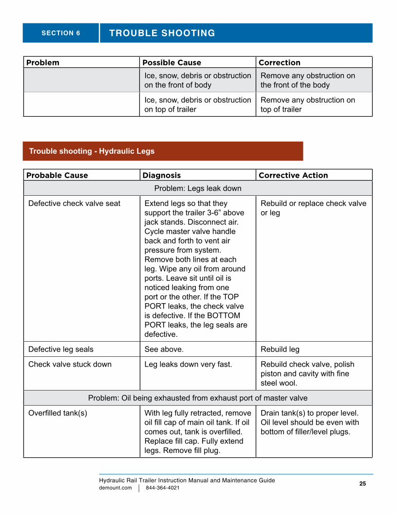
Problem Possible Cause Correction
Ice, snow, debris or obstruction on the front of body
Remove any obstruction on the front of the body
Ice, snow, debris or obstruction on top of trailer
Remove any obstruction on top of trailer
SECTION 6 TROUBLE SHOOTING
Probable Cause Diagnosis Corrective Action
Problem: Legs leak down
Defective check valve seat Extend legs so that they support the trailer 3-6” above jack stands. Disconnect air. Cycle master valve handle back and forth to vent air pressure from system. Remove both lines at each leg. Wipe any oil from around ports. Leave sit until oil is noticed leaking from one port or the other. If the TOP PORT leaks, the check valve is defective. If the BOTTOM PORT leaks, the leg seals are defective.
Rebuild or replace check valve or leg
Defective leg seals See above. Rebuild leg
Check valve stuck down Leg leaks down very fast. Rebuild check valve, polish piston and cavity with fine steel wool.
Problem: Oil being exhausted from exhaust port of master valve
Overfilled tank(s) With leg fully retracted, remove oil fill cap of main oil tank. If oil comes out, tank is overfilled. Replace fill cap. Fully extend legs. Remove fill plug.
Drain tank(s) to proper level. Oil level should be even with bottom of filler/level plugs.
Trouble shooting - Hydraulic Legs
Hydraulic Rail Trailer Instruction Manual and Maintenance Guide demount.com | 844-364-4021
26
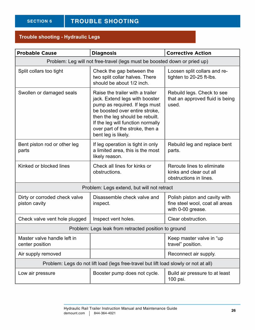
Probable Cause Diagnosis Corrective Action
Problem: Leg will not free-travel (legs must be boosted down or pried up)
Split collars too tight Check the gap between the two split collar halves. There should be about 1/2 inch.
Loosen split collars and re-tighten to 20-25 ft-lbs.
Swollen or damaged seals Raise the trailer with a trailer jack. Extend legs with booster pump as required. If legs must be boosted over entire stroke, then the leg should be rebuilt. If the leg will function normally over part of the stroke, then a bent leg is likely.
Rebuild legs. Check to see that an approved fluid is being used.
Bent piston rod or other leg parts
If leg operation is tight in only a limited area, this is the most likely reason.
Rebuild leg and replace bent parts.
Kinked or blocked lines Check all lines for kinks or obstructions.
Reroute lines to eliminate kinks and clear out all obstructions in lines.
Problem: Legs extend, but will not retract
Dirty or corroded check valve piston cavity
Disassemble check valve and inspect.
Polish piston and cavity with fine steel wool, coat all areas with 0-00 grease.
Check valve vent hole plugged Inspect vent holes. Clear obstruction.
Problem: Legs leak from retracted position to ground
Master valve handle left in center position
Keep master valve in “up travel” position.
Air supply removed Reconnect air supply.
Problem: Legs do not lift load (legs free-travel but lift load slowly or not at all)
Low air pressure Booster pump does not cycle. Build air pressure to at least 100 psi.
Trouble shooting - Hydraulic Legs
SECTION 6 TROUBLE SHOOTING
Hydraulic Rail Trailer Instruction Manual and Maintenance Guide demount.com | 844-364-4021
27
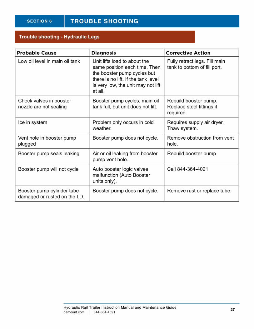
Probable Cause Diagnosis Corrective Action
Low oil level in main oil tank Unit lifts load to about the same position each time. Then the booster pump cycles but there is no lift. If the tank level is very low, the unit may not lift at all.
Fully retract legs. Fill main tank to bottom of fill port.
Check valves in booster nozzle are not sealing
Booster pump cycles, main oil tank full, but unit does not lift.
Rebuild booster pump. Replace steel fittings if required.
Ice in system Problem only occurs in cold weather.
Requires supply air dryer. Thaw system.
Vent hole in booster pump plugged
Booster pump does not cycle. Remove obstruction from vent hole.
Booster pump seals leaking Air or oil leaking from booster pump vent hole.
Rebuild booster pump.
Booster pump will not cycle Auto booster logic valves malfunction (Auto Booster units only).
Call 844-364-4021
Booster pump cylinder tube damaged or rusted on the I.D.
Booster pump does not cycle. Remove rust or replace tube.
Trouble shooting - Hydraulic Legs
SECTION 6 TROUBLE SHOOTING

For Service and Parts:
Tel: 844-364-4021
Local: 856-863-0900
Fax 856-863-6704
E-mail: [email protected]
Web: demount.com
To preview, or order parts online visit dcixpress.com Click on the
Demountable Parts link.
NOTICE
© 2020 Demountable Concepts, Inc. 0484-A