Embed Size (px)
Citation preview

Hyd
raul
ics
Parker Hannifin CorporationQuick Coupling DivisionMinneapolis, MN www.parker.com/quickcouplings
Hydraulic Quick CouplingsDouble Shut-Off and Straight-Thru CouplingsParker hydraulic couplings have a wide variety of designs, each tailored to a particular application or use. This catalog is arranged according to those categories. In each section the construction of a specific design will be detailed. However, based on the valving of the coupling, hydraulic couplings generally fall into one of two groups, either Double Shut-Off or Straight-Thru.
Double Shut-Off couplings are used extensively when it is important to minimize fluid loss upon disconnection. Both halves of the coupler, the body and the nipple, contain shut-off valves. These valves open automatically when the body and nipple are connected, and close automatically when the two halves are disconnected—keeping fluid loss to a minimum.
Parker Straight-Thru couplings have no valves in either half and are ideal for maximum flow application. Their smooth, open bore offers the lowest pressure drop of any quick disconnect coupling, and allows them to be thoroughly cleaned. Since there are no valves in either half, fluid flow should be shut off before the coupling is disconnected.
Rated PressureRated pressure for the Parker hydraulic couplings range from 30 to 15,000 psi, depending on the coupling series, size and materials. Rated pressures as shown in this catalog are defined by ISO 5598, as “the qualified operating pressures which are recommended for a component or a system by the manufacturer.” Parker “Rated Pressures” have been established on the basis of laboratory tests which include, but are not limited to, static burst tests and multiple cycle impulse tests. System characteristics such as high cycling rates and high amplitude shocks either hydraulic or mechanical, can reduce the functioning life of a coupling, even if the system’s nominal pressure falls within the rated pressure range of the coupling.
For assistance in analyzing your application, contact your nearest Parker sales office or the Quick Coupling Division in Minneapolis.
Refer to the Safety Guide at the end of this catalog for considerations when selecting a Quick Coupling.
Refer to the Fluid Compatibility Chart (note Table of Contents) for seal selection assistance for both Double Shut-Off and Straight-Thru couplings.
Checklist for Selecting Quick Couplingsq What are the functional requirements of the coupling?
q What is the maximum working pressure of the application?
q Which seals and body material are compatible with the system’s fluid?
q Is the application static or dynamic?
q What size coupler is required?
q What is the maximum pressure drop suitable for the application?
q Does the application require the ability to connect and disconnect under pressure?
q What is the media temperature and ambient temperature?
q What end configurations are required?
q Is an industry interchange coupler required?
q Is air inclusion and fluid loss a concern in the application?

Hyd
raul
ics
Parker Hannifin CorporationQuick Coupling DivisionMinneapolis, MN www.parker.com/quickcouplings
Table of ContentsIntroduction .....................................................................B-1
Coupling Selection & Ordering Guide ...........................B-3
General Purpose Couplings
60 Series........................................................................B-4 Couplers.............................................................B-6, B-7 Nipples................................................................B-6, B-7 60 Series Steam...........................................................B-9 Couplers......................................................................B-9 Nipples........................................................................B-9 6600 Series.....................................................................B-10 Couplers.....................................................................B-11 Nipples.......................................................................B-11 SM Series.......................................................................B-13 Couplers..................................................................B-14 Nipples...................................................................B-14 HP Series........................................................................B-16 Couplers.....................................................................B-17 Nipples.......................................................................B-17 4000 Series.....................................................................B-18 Couplers.....................................................................B-19 Nipples.......................................................................B-19 4200 Series....................................................................B-21 Couplers....................................................................B-22 Nipples.......................................................................B-22
Non-Spill Couplings NS Series........................................................................B-23 Couplers...................................................................B-24 Nipples...................................................................B-24 EAS/SAE Adapters........................................................B-25 FF/FC Series....................................................................B-26 Couplers.....................................................................B-27 Nipples.......................................................................B-27 FC Nipples.................................................................B-29 FEM/FEC Series.......................................................B-30 Couplers..............................................................B-31 Nipples................................................................B-32 FEC Nipples.............................................................B-33 FH Series.................................................................B-34
Couplers..............................................................B-35 Nipples................................................................B-35
FS Series.................................................................B-36 Couplers..............................................................B-37 Nipples................................................................B-37 Repair Kits...........................................................B-38
Connect Under Pressure Couplings 6100 Series.............................................................B-39 Couplers.............................................................B-40 Nipples................................................................B-41 8200 Series..............................................................B-42 Couplers..............................................................B-43 Nipples................................................................B-43 9200 Series..............................................................B-44 Couplers..............................................................B-45 Nipples................................................................B-45 5000 Series..............................................................B-46 Couplers..............................................................B-47 Nipples................................................................B-47
High Pressure Couplings 3000 Series..............................................................B-48 Couplers.............................................................B-49 Nipples................................................................B-49 TC Series..................................................................B-50 Couplers..............................................................B-50 Nipples................................................................B-50 1141 Series..............................................................B-51 Couplers..............................................................B-51 Nipples................................................................B-51 High Flow Couplings ST Series..................................................................B-52 Couplers.............................................................B-53 Nipples................................................................B-54 1163 Series..............................................................B-55 Couplers.............................................................B-55 Nipples................................................................B-55 HO Series.................................................................B-56 Couplers.............................................................B-56 Nipples................................................................B-56
Mold Coolant Line Couplings Moldmate Series......................................................B-57 Couplers..............................................................B-58 Sub Assemblies & Replacement Parts..............B-59 Nipples................................................................B-61
Special Purpose - Miniature DM Series................................................................B-63 Couplers........................................................B-64 Nipples................................................................B-64 Ordering Information and Options ............................B-65
Promotional Products-Keychains..............................B-66

B-3
Body Sizes (in.)
Valving Style MaterialB S S3 S6
Locking Mechanism
Std Seal Material*
Std Seal Temp Range
Rated Pressure
Coupling Series
General Purpose1/8 to 2-1/2 Poppet n n n n Ball Nitrile -40° to +250° F 800-5000 psi 60 Series
1/4 to 1 Poppet n Ball EthylenePropylene -65° to +400° F 60 Series
(steam)1/4 to 1 Poppet n Ball Nitrile -40° to +250° F 4000-5000 psi 6600 Series
1/4 to 3/4 Poppet n Ball Nitrile -40° to +250° F 4500-6000 psi SM Series
1 to 1-1/2 Poppet n Ball Nitrile -40° to +250° F 5000 psi HP Series
1/4 to 1 Poppet/Ball n Ball Nitrile -40° to +250° F 3000 psi 4000 Series
3/8 to 1/2 Poppet/Ball n Ball Nitrile -40° to +250° F 3000 psi 4200 Series
Non-Spill
3/8 to 1 Flush Face n Ball Nitrile -40° to +250° F 2500 psi NS Series
1/2 Flush Face/Poppet n Ball Nitrile/Polyurethane -40° to +250° F 3000-3625 psi EAS/SAE
Adapters
1/4 to 1 Flush Face n Ball Nitrile/Polyurethane -40° to +250° F 3000-5000 psi FF Series
1/4 to 1 Flush Face n Ball Nitrile/Polyurethane -40° to +250° F 3000-5000 psi FEM Series
1/4 to 1 Flush Face n Ball Fluorocarbon -15° to +400° F 2000 psi FS Series
Non-Spill Connect Under Pressure
3/8 to 3/4 Flush Face n Ball Nitrile/Polyurethane -40° to +250° F 3000 psi FC Series
1/2 to 3/4 Flush Face n Ball Nitrile/Polyurethane -40° to +250° F 3000 psi FEC Series
3/4 to 1-1/2 Flush Face n Threads Nitrile -40° to +250° F 2000-3000 psi 6100 Series
Connect Under Pressure
1/2 Poppet n Ball Nitrile -40° to +250° F 3000 psi 8200 Series
1/2 Poppet n Ball Nitrile -40° to +250° F 3000 psi 9200 Series
1/2 Ball n Threads Nitrile -40° to +250° F 2500 psi 5000 Series
High Pressure
3/8 Flush Face n Ball Nitrile -40° to +250° F 10,000 psi FH Series
1/4 to 3/8 Ball n Threads Polyurethane -22° to +230° F 10,000 psi 3000 Series
3/8 Poppet n Ball Fluorocarbon -15° to +400° F 10,000 psi TC Series
1/4 Poppet n Threads Polyurethane -22° to +230° F 10,000 psi 1141 Series
High Flow
1/8 to 1-1/2 Unvalved n n n Ball Nitrile -40° to +250° F 2500-6700 psi ST Series
1/4 to 1/2 Unvalved n Ball Nitrile -40° to +250° F 10,000-15,000 psi HO Series
3/4 Unvalved n Ball Nitrile -40° to +250° F 200 psi 1163 Series
Mold Coolant
1/4 to 1/2 Valved/Unvalved n Ball Silicone -20° to +400° F 200 psi Moldmate
Miniature
1/8 Poppet n Ball Fluorocarbon -15° to +400° F 250 psi DM Series
Hydraulic Coupling Selection Guide
Seal Code Seal Material Optional for the Following SeriesW Ethylene Propylene 60, 6600, 4000, 4200, 6100, 5000, 8200, 9200, ST
Y Fluorocarbon 60, 6600, 4000, 4200, 6100, 5000, 8200, 9200, ST, Moldmate
Z Neoprene 60, 6600, 4000, 4200, 6100, 5000, 8200, 9200, ST
E5 Ethylene Propylene SM, HP, NS, FF, FEM, FH, FS, HO
E4 Fluorocarbon SM, HP, NS, FF, FEM, FH, HO
E12 Neoprene SM, HP, NS, FF, FEM, FH, FS, HO
E35 Perfluoroelastomer SM, HP, NS, FF, FEM, FH, FS (Contact QCD)
* Seal Material Options
To select proper seal materials, see Fluid Compatibility Chart or contact QCD.
Parker Hannifin CorporationQuick Coupling DivisionMinneapolis, MN www.parker.com/quickcouplings
B H
ydra
ulic
s
Materials: B - Brass
S - Steel
S3 - 303 Stainless
S6 - 316 Stainless

B-4
60 Series double shut-off couplings are versatile for use across a spectrum of hydraulic applications where fluid lines require connection and disconnection. Couplers and nipples are available in a wide range of sizes and materials.
Features:• Accepts ISO 7241-1, Series B compliant nipples
• Poppet valves along with a metal to metal valve stop maintains valve alignment and prevents flow checking
• Steel, brass, and stainless steel material options
• Brass couplers have double O-rings and stainless steel locking balls
• Steel coupler sleeve and steel nipple body are hardened to be wear resistant
• Standard end configurations include female pipe and straight thread ORB
• Optional Sleeve-Lok and alternative seal materials available
Applications include:• Industrial hydraulic lines
• Food and chemical processing
• Water and coolant lines
• Mobile equipment
• May be used with some gases
60 SeriesISO 7241, Series BManual sleeve, poppet valve
Hydraulic Quick Couplings General Purpose
General Purpose Specifications Industry Standard: Parker 60 Series couplings comply with ISO 7241 Series B Standard.
ANSI/ISO Pressure Rating: Dynamic applications with normal to moderate hydraulic shocks such as general industrial equipment, hydraulic presses, agricultural equipment, etc. Impulse tested at a multiple (125% to 133%) of rated pressure.
Low Cycle, Non-pulsating Pressure Rating: Applications with lower cycle life and no severe cyclic pressure fluctuations, essentially steady pressure during an operating cycle. Typical applications include hydraulic jacks, mine roof support systems, and high pressure fluid transfer (pumping water or slurry in oil wells). Minor pump ripple is considered non-pulsating. Impulse tested at rated pressure.
Body Size 1/8 1/4 3/8 1/2 3/4 1 1 1/2 2 1/2 1/8 1/4 3/8 1/2 3/4 1 1 1/2 2 1/2
Rated Pressure (psi) Rated Pressure (psi)
Brass 1000 1000 1000 1000 1000 1000 800 800 3000 3700 2700 3500 2200 1500 1500 1200Stainless steel 2000 2000 1500 1500 1500 1000 1000 1000 5000 5000 5000 5000 3000 3000 1500 1500
Steel 5000 5000 4000 4000 2500 2000 1000 1000 5000 5000 4000 4000 2500 2000 1500 1500Steel w/ HD nipple N/A 5000 4000 4000 3000 3000 N/A N/A 5000 5000 4000 4000 3000 3000 N/A N/A
Seal Temperature Range: Nitrile: -40°F to +250°F (Standard seal for Brass, Steel, & 303 Stainless Steel couplings). Fluorocarbon: -15°F to +400°F (Standard seal for 316 Stainless Steel couplings). Other Seal materials: Contact the Division for availability.
Vacuum Data: 27.4 inches Hg. both connected and disconnected (1-1/2” and 2-1/2” body size 60 Series couplings are not recommended for service in disconnected mode)
Body Size 1/8 1/4 3/8 1/2 3/4 1 1 1/2 2 1/2
Rated Flow (gpm) .8 3 6 12 28 50 100 200
Parker Hannifin CorporationQuick Coupling DivisionMinneapolis, MN www.parker.com/quickcouplings
B H
ydra
ulic
s

B-5
Hydraulic Quick Couplings General Purpose
60 SeriesISO 7241, Series BManual sleeve, poppet valve
Performance
60 Series (1/8" & 1/4")Test Fluid: Oil - 150 SUS
0
5
10
15
20
25
30
0 0.5 1 1.5 2 2.5 3 3.5 4 4.5
Flow in USGPM
Pres
sure
Drop
in PS
ID
1/8"
1/4"
60 Series (3/8" & 1/2")Test Fluid: Oil - 150 SUS
0
5
10
15
20
25
30
35
40
0 2 4 6 8 10 12 14 16 18Flow in USGPM
Pres
sure
Drop
in PS
ID
3/8"
1/2"
60 Series (3/4" & 1")Test Fluid: Oil - 150 SUS
0
5
10
15
20
25
30
35
40
45
0 10 20 30 40 50 60 70
Flow in USGPM
Pressure Drop
in PS
ID
3/4"
1"
60 Series (1-1/2" & 2-1/2")Test Fluid: Oil - 200 SUS
0
20
40
60
80
100
120
140
0 50 100 150 200 250 300Flow in USGPM
Pressure Drop
in PS
ID
1-1/2"
2-1/2"
Parker Hannifin CorporationQuick Coupling DivisionMinneapolis, MN www.parker.com/quickcouplings
B H
ydra
ulic
s

B-6
60 SeriesISO 7241, Series BManual sleeve, poppet valve
Hydraulic Quick Couplings General Purpose
* This dimension represents the portion that is exposed when the nipple is inserted into the mating Parker Coupler.
Nipples - Female Thread
Body Size
Part No. Brass
Weight(lbs.)
Part No. Steel
Weight(lbs.)
Part No.Type 303 Stainless
Weight(lbs.)
Part No.Type 316 Stainless
Weight(lbs.)
ThreadSize
OverallLength
ExposedLength*
WrenchFlats
LargestDiameter
1/8 BH1-61 0.04 H1-63 0.03 SH1-63 0.03 SSH1-63Y 0.04 1/8-27 NPTF 1.26 0.44 0.96 0.96
1/8 - 0.06 H1-63-T4 0.05 SH1-63-T4 - SSH1-63Y-T4 0.06 7/16-20 ORB 1.41 0.59 0.96 0.96
1/4 BH2-61 0.09 H2-63 0.08 SH2-63 0.08 SSH2-63Y 0.08 1/4-18 NPTF 1.54 0.55 1.14 1.14
1/4 – 0.11 H2-63-T6 0.10 SH2-63-T6 0.10 SSH2-63Y-T6 0.10 9/16-18 ORB 1.69 0.70 1.14 1.14
3/8 BH3-61 0.10 H3-63 0.12 SH3-63 0.12 SSH3-63Y 0.12 3/8-18 NPTF 1.68 0.54 1.40 1.40
3/8 – 0.12 H3-63-T8 0.16 SH3-63-T8 0.16 SSH3-63Y-T8 0.14 3/4-16 ORB 1.94 0.80 1.40 1.40
1/2 BH4-61 0.25 H4-63 0.24 SH4-63 0.24 SSH4-63Y 0.24 1/2-14 NPTF 1.94 0.69 1.77 1.77
1/2 - 0.28 H4-63-T10 0.27 SH4-63-T10 0.27 SSH4-63Y-T10 0.27 7/8-14 ORB 2.12 0.87 1.77 1.77
3/4 BH6-61 0.50 H6-63 0.46 SH6-63 0.45 SSH6-63Y 0.46 3/4-14 NPTF 2.43 0.79 2.14 2.14
3/4 – 0.55 H6-63-T12 0.46 SH6-63-T12 0.50 SSH6-63Y-T12 0.50 1-1/16-12 ORB 2.54 0.90 2.14 2.14
1 BH8-61 0.76 H8-63 0.76 SH8-63 0.76 SSH8-63Y 0.76 1-11 1/2 NPTF 2.91 0.99 2.52 2.52
1 – 0.80 H8-63-T16 0.80 SH8-63-T16 0.80 SSH8-63Y-T16 0.80 1-5/16-12 ORB 2.91 0.99 2.52 2.52
Couplers - Female Thread
Body Size
Part No.
Brass
Weight(lbs.)
Part No. Steel
Weight(lbs.)
Part No.Type 303 Stainless
Weight(lbs.)
Part No.Type 316 Stainless
Weight(lbs.)
ThreadSize
OverallLength
WrenchFlats
LargestDiameter
1/8 BH1-60 0.16 H1-62 0.16 SH1-62 0.16 SSH1-62Y 0.15 1/8-27 NPTF 1.90 0.68 0.96
1/8 - - H1-62-T4 0.18 SH1-62-T4 0.10 SSH1-62Y-T4 0.17 7/16-20 ORB 2.06 0.68 0.96
1/4 BH2-60 0.32 H2-62 0.30 SH2-62 0.30 SSH2-62Y 0.30 1/4-18 NPTF 2.26 0.81 1.14
1/4 – - H2-62-T6 0.31 SH2-62-T6 0.31 SSH2-62Y-T6 0.31 9/16-18 ORB 2.41 0.81 1.14
3/8 BH3-60 0.43 H3-62 0.40 SH3-62 0.40 SSH3-62Y 0.40 3/8-18 NPTF 2.49 0.88 1.40
3/8 – - H3-62-T8 0.51 SH3-62-T8 0.51 SSH3-62Y-T8 0.51 3/4-16 ORB 2.75 1.00 1.40
1/2 BH4-60 0.80 H4-62 0.73 SH4-62 0.75 SSH4-62Y 0.76 1/2-14 NPTF 2.87 1.12 1.77
1/2 - - H4-62-T10 0.78 SH4-62-T10 0.75 SSH4-62Y-T10 0.78 1-1/16-12 ORB 3.05 1.12 1.77
3/4 BH6-60 - H6-62 1.30 SH6-62 1.31 SSH6-62Y 1.33 3/4-14 NPTF 3.56 1.31 2.14
3/4 – - H6-62-T12 1.39 SH6-62-T12 1.34 SSH6-62Y-T12 1.40 1-1/16-12 ORB 3.56 1.31 2.14
1 BH8-60 - H8-62 1.95 SH8-62 1.95 SSH8-62Y 1.95 1-11 1/2 NPTF 4.18 1.62 2.52
1 – - H8-62-T16 1.95 SH8-62-T16 1.95 SSH8-62Y-T16 1.95 1-5/16-12 ORB 4.18 1.62 2.52
Parker Hannifin CorporationQuick Coupling DivisionMinneapolis, MN www.parker.com/quickcouplings
B H
ydra
ulic
s

B-7
Couplers - Female Thread
Body Size
Part No. Brass
Weight(lbs.)
Part No.Steel
Weight(lbs.)
Part No.Type 303 Stainless
Weight(lbs.)
Part NumberType 316 Stainless
Weight(lbs.)
ThreadSize
OverallLength
WrenchFlats
LargestDiam-eter
1 1/2 BH12-60L 4.58 H12-62L 4.70 SH12-62L 4.68 SSH12-62LY 4.68 1 1/4-11 1/2 NPTF 4.86 2.38* 3.00
1 1/2 BH12-60N 4.58 H12-62N 4.70 SH12-62N 4.68 SSH12-62NY 4.68 1 1/2-11 1/2 NPTF 4.86 2.38* 3.00
1 1/2 – 4.61 H12-62-T20 4.72 SH12-62-T20 4.71 SSH12-62Y-T20 4.71 1 5/8-12 ORB 4.86 2.38* 3.00
1 1/2 – 4.61 H12-62-T24 4.72 SH12-62-T24 4.71 SSH12-62Y-T24 4.71 1 7/8-12 ORB 4.86 2.38* 3.00
2 1/2 BH2016-60 11.06 H2016-62 10.58 SH2016-62 – SSH2016-62Y – 2-11 1/2 NPTF 5.57 3.75 4.10
2 1/2 BH2020-60 11.42 H2020-62 10.91 SH2020-62 – SSH2020-62Y – 2 1/2-8 NPTF 6.04 3.75 4.10
2 1/2 BH2024-60 – H2024-62 – SH2024-62 – SSH2024-62Y – 3-8 NPTF 6.69 4.00 4.35
60 SeriesISO 7241, Series BManual sleeve, poppet valve
Hydraulic Quick Couplings General Purpose
*Wrench Flat on 303 Stainless is 2.50 in.
Nipples - Female Thread
Body Size
Part No. Brass
Weight(lbs.)
Part No. Steel
Weight(lbs.)
Part No.Type 303 Stainless
Weight(lbs.)
Part No.Type 316 Stainless
Weight(lbs.)
ThreadSize
OverallLength
ExposedLength*
WrenchFlats
LargestDiameter
1 1/2 BH12-61L 2.96 H12-63L 3.10 SH12-63L 3.06 SSH12-63LY – 1 1/4-11 1/2 NPTF 4.76 2.69 2.38‡ 2.75†
1 1/2 BH12-61N 2.96 H12-63N 3.10 SH12-63N 3.06 SSH12-63NY – 1 1/2-11 1/2 NPTF 4.76 2.69 2.38‡ 2.75†
1 1/2 – - H12-63-T20 3.15 SH12-63-T20 3.14 SSH12-63Y-T20 – 1 5/8-12 ORB 4.76 2.69 2.38‡ 2.75†
1 1/2 – - H12-63-T24 3.15 SH12-63-T24 3.14 SSH12-63Y-T24 - 1 7/8-12 ORB 4.76 2.69 2.38‡ 2.75†
2 1/2 BH2016-61 7.78 H2016-63 7.90 SH2016-63 7.92 SSH2016-63Y – 2-11 1/2 NPTF 5.48 2.90 3.75 4.10
2 1/2 BH2020-61 8.12 H2020-63 8.16 SH2020-63 8.16 SSH2020-63Y – 2 1/2 -8 NPTF 5.95 3.37 3.75 4.10
2 1/2 BH2024-61 – H2024-63 – SH2024-63 – SSH2024-63Y – 3-8 NPTF 6.87 4.29 4.00 4.35
* This dimension represents the portion that is exposed when the nipple is inserted into the mating Parker Coupler.† Largest diameter on Brass is 2.96” across Hex Corners‡ Hex on 303 Stainless is 2.50 in.
Parker Hannifin CorporationQuick Coupling DivisionMinneapolis, MN www.parker.com/quickcouplings
B H
ydra
ulic
s
Contact QCD for availability and additional options.To select proper seal materials, see Fluid Compatibility Chart or contact QCD.
Code Description Part Number Examplesuffix -VA Valve actuator (Nipples) H3-63-VAsuffix -SL Sleeve-Lok (Couplers) H3-62-SLprefix HD Heavy duty (Steel Nipples) HDH3-63suffix W Ethylene Propylene seal material (EPR) H3-63Wsuffix Y Fluorocarbon seal material H3-62Ysuffix Z Neoprene seal material H3-63Z
Optional Materials and Features:(add code to part number)

B-8
60 Series Dust Plugs and Caps
Body Size
Dust PlugAluminum
Dust PlugRubber
Dust CapAluminum
Dust CapRubber
1/8 H1-65 H1-65M H1-66 H1-66M
1/4 H2-65 H2-65M H2-66 H2-66M
3/8 H3-65 H3-65M H3-66 H3-66M
1/2 H4-65 H4-65M H4-66 H4-66M
3/4 H6-65 H6-65M H6-66 H6-66M
1 H8-65 H8-65M H8-66 H8-66M
1-1/2 H12-65 - H12-66 -
2-1/2 H20P-65 - H20P-66 -
Replacement Parts60 Series Couplers
Body Size O-Rings - Nitrile Back-Up Rings
1/8 50001-013-0010 H67A-28
1/4 50001-015-0010 H67C-28
3/8 50001-116-0010 4118007
1/2 50001-213-0010 4128002
3/4 50001-218-0010 4148001
1 50001-222-0010 4158001
1-1/2 50001-124-0010 (Valve)
1-1/2 50001-138-0260 (Fitting)
1-1/2 50001-224-0010 (Body 2 req.)
2-1/2 50001-133-0010 (Valve)
2-1/2 50001-234-0260 (Fitting)
2-1/2 50001-333-0010 (Body)
60 SeriesISO 7241, Series BManual sleeve, poppet valve
Hydraulic Quick Couplings General Purpose
Repair KitsCouplers Nipples
Body Size
Repair KitPart No.
Used forPart No.
Repair KitPart No.
Used forPart No.
3/8 H67E-62K H3-62 H67E-63K H3-63
3/8 BH67E-60K BH3-60 BH67E-61K BH3-61
3/8 SH67E-62K SH3-62 SH67E-63K SH3-63
3/8 SSH67-62KY SSH3-62Y SSH67E-63KY SSH3-63Y
1/2 H67F-62K H4-62 H67F-63K H4-63
1/2 BH67F-60K BH4-60 BH67F-61K BH4-61
1/2 SH67F-62K SH4-62 SH67F-63K SH4-63
1/2 SSH67F-62KY SSH4-62Y SSH67F-63KY SSH4-63Y
3/4 H67G-62K H6-62 H67G-63K H6-63
3/4 BH67G-60K BH6-60 BH67G-61K BH6-61
3/4 SH67G-62K SH6-62 SH67G-63K SH6-63
3/4 SSH67G-62KY SSH6-62Y SSH67G-63KY SSH6-63Y
1 H67J-62K H8-62 H67J-63K H8-63
1 BH67J-60K BH8-60 BH67J-61K BH8-61
1 SH67J-62K SH8-62 SH67J-63K SH8-63
1 SSH67J-62KY SSH8-62Y SSH67J-63KY SSH8-63Y
Parker Hannifin CorporationQuick Coupling DivisionMinneapolis, MN www.parker.com/quickcouplings
B H
ydra
ulic
s

B-9
Couplers - Female Pipe Thread
Body Size
Part No. Brass Thread Size Length Largest Diameter Wrench Flats Weight (lbs.)
1/4 BH2-60-STM 1/4-18 NPTF 2.26 1.14 0.81 0.303/8* H3-68 3/8-18 NPTF 2.50 1.77 0.88 0.50
1/2 BH4-60-STM 1/2-14 NPTF 2.87 1.77 1.12 0.75
3/4 BH4-60-STM 3/4-14 NPTF 3.56 2.14 1.31 1.31
1 BH4-60-STM 1-11 1/2 NPTF 4.18 2.52 1.62 1.95
Nipple - Female Pipe Thread
Body Size
Part No. Brass Thread Size Overall
LengthExposed*
LengthLargest
DiameterWrench
FlatsWeight (lbs.)
1/4 BH2-61-STM 1/4 - 18 NPTF 1.54 0.65 0.87 0.75 0.08
3/8 H3-69 3/8 - 18 NPTF 1.68 0.52 1.01 0.88 0.13
1/2 BH4-61-STM 1/2 - 14 NPTF 1.94 0.69 1.30 1.12 0.24
3/4 BH6-61-STM 3/4 - 14 NPTF 2.43 0.79 1.59 1.38 0.46
1 BH8-61-STM 1 - 11 1/2 NPTF 2.91 0.99 1.88 1.62 0.76
60 Series (Steam)ISO 7241, Series BManual sleeve, EP seal
Hydraulic Quick Couplings General Purpose
60 Series Steam couplings are brass with stainless steel locking balls and ethylene propylene seals to withstand temperatures up to 400 F. 1/4 to 1 inch body sizes. 3/8 inch size couplers have a grip-ring sleeve.
Features:
• Accepts ISO 7241-1, Series B compliant nipples
• Poppet valves along with a metal to metal valve stop maintains valve alignment and prevents flow checking
• Brass couplers have double O-rings and stainless steel locking balls
• Standard end configuration is female pipe thread
Applications:
• Steam systems
• Cleaning equipment
Specifications Body Size 1/4 to 1
Standard Seal Material Ethylene Propylene
Temperature Range up to +400°
* See Photo for 3/8 inch size coupler configuration.
* This dimension represents the portion that is exposed when the nipple is inserted into the mating Parker Coupler.
Repair Kits - Steam CouplingBody Size Repair Kit Part No. Used for Part No.
3/8 H68E-67K H3-68
3/8 H69E-67K H3-69
H3-68 has grip-ring sleeve
Parker Hannifin CorporationQuick Coupling DivisionMinneapolis, MN www.parker.com/quickcouplings
B H
ydra
ulic
s

B-10
6600 Series Specifications:Body Size Rated Flow (gpm) Rated Pressure (psi) Temperature Body Material Sleeve Type Seal Material
1/4 0.8 5000
-40° F to +250° F Steel Manual Connect Nitrile
3/8 6 4000
1/2 12 4000
3/4 28 4000
1 50 4000
Performance:6600 Series (1/4")
Test Fluid: Oil - 150 SUS
0
5
10
15
20
25
0 0.2 0.4 0.6 0.8 1 1.2
Flow in USGPM
Pressure Drop
in PS
ID
1/4"
The 6600 Series are versatile for use in a wide range of hydraulic applications where fluid lines require connection and disconnection for equipment operation or maintenance
Features:• Accepts ISO 7241-1, Series A compliant nipples
• Poppet valves and a metal perch to maintain valve alignment and prevent flow checking
• Coupler sleeve and nipple body are hardened to be damage resistant
• Standard end configurations include female pipe and straight thread ORB
• Protective zinc plating with clear trivalent chromate finish
Applications include:• Snow plows
• Truck trailer connections
• Mobile applications
• Attachments
6600 Series (3/8"& 1/2")Test Fluid: Oil - 150 SUS
0
5
10
15
20
25
30
35
40
45
0 2 4 6 8 10 12 14 16 18Flow in USGPM
Pres
sure
Drop
in PS
ID
3/8"
1/2"
6600 Series (3/4" & 1")Test Fluid: Oil - 150 SUS
0
5
10
15
20
25
30
35
40
45
50
0 10 20 30 40 50 60 70
Flow in USGPM
Pressure Drop
in PS
ID
3/4"
1"
Hydraulic Quick Couplings General Purpose
Parker Hannifin CorporationQuick Coupling DivisionMinneapolis, MN www.parker.com/quickcouplings
B H
ydra
ulic
s6600 SeriesISO 7241 Series AManual sleeve, poppet valve

B-11
6600 Series Nipples
Body Size
NipplePart Number Port End Valve Type Length Exposed
Length*Largest
Diameter Wrench Flats Weight (lbs.)
1/4 6602-2-4 1/8-27 NPTF Poppet 1.41 0.50 0.65 0.56 0.05
1/4 6602-4-4 1/4-18 NPTF Poppet 1.41 0.58 0.87 0.75 0.07
3/8 6602-6-6 3/8-18 NPTF Poppet 1.63 0.72 1.01 0.88 0.11
3/8 6610-6-6 9/16-18 ORB Poppet 1.63 0.72 1.01 0.88 0.13
1/2 6602-8-10 1/2-14 NPTF Poppet 2.08 0.78 1.23 1.06 0.21
1/2 6602-12-10 3/4-14 NPTF Poppet 2.30 0.78 1.59 1.38 0.33
1/2 6610-8-10 3/4-16 ORB Poppet 2.08 0.76 1.23 1.06 0.22
1/2 6610-10-10 7/8-14 ORB Poppet 2.08 0.82 1.30 1.12 0.21
1/2 6610-12-10 1 1/16 -12 ORB Poppet 2.30 1.04 1.59 1.38 0.33
3/4 6602-12-12 3/4-14 NPTF Poppet 2.55 1.18 1.59 1.38 0.49
3/4 6610-12-12 1 1/16-12 ORB Poppet 2.55 1.18 1.59 1.38 0.47
1 6602-16-16 1-11 1/2 NPTF Poppet 3.10 1.34 1.88 1.62 0.75
1 6610-16-16 1-5/16-12 ORB Poppet 3.10 1.34 2.17 1.62 0.72
6600 Series Couplers
Body Size
CouplerPart Number Port End Valve Type Length Largest
Diameter Wrench Flats Weight (lbs.)
1/4 6601-2-4 1/8-27 NPTF Poppet 1.85 1.08 0.88 0.27
1/4 6601-4-4 1/4-18 NPTF Poppet 1.85 1.08 0.88 0.26
3/8 6601-6-6 3/8-18 NPTF Poppet 2.18 1.27 1.06 0.39
3/8 6608-6-6 9/16-18 ORB Poppet 2.18 1.27 1.06 0.38
1/2 6601-8-10 1/2-14 NPTF Poppet 2.75 1.52 1.25 0.67
1/2 6601-12-10 3/4-14 NPTF Poppet 2.88 1.52 1.38 0.71
1/2 6608-8-10 3/4-16 ORB Poppet 2.74 1.52 1.25 0.67
1/2 6608-10-10 7/8 -14 ORB Poppet 2.79 1.52 1.25 0.64
1/2 6608-12-10 1 1/16-12 ORB Poppet 3.01 1.52 1.38 0.77
3/4 6601-12-12 3/4 -14 NPTF Poppet 3.36 1.90 1.62 1.31
3/4 6608-12-12 1 1/16-12 ORB Poppet 3.35 1.90 1.62 1.31
1 6601-16-16 1-11 1/2 NPTF Poppet 4.11 2.14 1.88 1.93
1 6608-16-16 1 5/16-12 ORB Poppet 4.11 2.14 1.88 1.75
6600 Series Replacement Parts 1/4 3/8 1/2 3/4 1
O-Rings - Nitrile 50001-112-0010 50001-115-0010 50001-211-0010 50001-123-0010 50001-126-0010
Back-up Rings 4118006 4118005 50-140-4 4138001 4148002
Parker Hannifin CorporationQuick Coupling DivisionMinneapolis, MN www.parker.com/quickcouplings
B H
ydra
ulic
s
6600 SeriesISO 7241 Series AManual sleeve, poppet valve
Hydraulic Quick Couplings General Purpose
* This dimension represents the portion of the nipple that is exposed when the nipple and coupler are connected.

B-12
6600 Series Dust Caps and Plugs
Body Size Dust Cap Color/Material Dust Plug Weight
(lbs.)
1/4 H1-65M Black Rubber H1-66M .02
3/8 TR-37 Black Rubber TR-37 .04
1/2 5205-4M Black Rubber 5209-4M .04
3/4 6659-12M Black Rubber 6657-12M .06
1 6659-16M Black Rubber 6657-16M .08
Parker Hannifin CorporationQuick Coupling DivisionMinneapolis, MN www.parker.com/quickcouplings
B H
ydra
ulic
s6600 SeriesISO 7241, Series AManual sleeve, poppet valve
Hydraulic Quick Couplings General Purpose
Contact QCD for availability and additional options.To select proper seal materials, see Fluid Compatibility Chart or contact QCD.
Code Description Part Number Examplesuffix -SL Sleeve-Lok (Couplers) 6601-6-6-SLsuffix W Ethylene Propylene seal material (EPR) 6601-6-6Wsuffix Y Fluorocarbon seal material 6601-6-6Ysuffix Z Neoprene seal material 6601-6-6Z
Optional Materials and Features:(add code to part number)

B-13 Parker Hannifin CorporationQuick Coupling DivisionMinneapolis, MN www.parker.com/quickcouplings
B H
ydra
ulic
s
PerformanceSM Series (1/4")
Test Fluid: Oil - 200 SUS
0
5
10
15
20
25
0 0.5 1 1.5 2 2.5 3 3.5 4 4.5
Flow in USGP M
Pre
ssure Drop
in PSID
1/4"
SM Series (1/2" & 3/4")Test Fluid: Oil - 200 SUS
0
5
10
15
20
25
30
35
0 5 10 15 20 25 30 35 40
Flow in USGP M
Pressur
e Drop
in PSID
1/2"
3/4"
SM SeriesHigh PressureManual sleeve, poppet valve
Hydraulic Quick CouplingsGeneral Purpose
SM Series double shut-off couplings are versatile for use across a spectrum of hydraulic applications where fluid lines require connection and disconnection. Couplers and nipples are steel with nitrile seals and are available in 1/4 through 3/4 inch sizes.
Features:
• Rated pressures up to 6000 psi
• Poppet valves have captive seals to minimize seal washout
• Steel material with standard nitrile seals
• Standard end configurations include female pipe, straight thread ORB, and British pipe
• Alternative seal materials available
Applications:• Industrial hydraulic lines
• Mobile equipment
Specifications Body Size 1/4 1/2 3/4
Rated Pressure (PSI) 6,000 6,000 4,500
Rated Flow (GPM) 3 12 28
Temperature Range (Nitrile Seals) -40° to +250°F
Contact QCD for availability and additional options.To select proper seal materials, see Fluid Compatibility Chart or contact QCD.
Code Description Part Number Examplesuffix -SL Sleeve-Lok (Couplers) SM-501-8FP-SLsuffix -E5 Ethylene Propylene seal material (EPR) SM-501-8FP-E5suffix -E4 Fluorocarbon seal material SM-501-8FP-E4suffix -E12 Neoprene seal material SM-501-8FP-E12
Optional Materials and Features:(add code to part number)

B-14 Parker Hannifin CorporationQuick Coupling DivisionMinneapolis, MN www.parker.com/quickcouplings
B H
ydra
ulic
s
Nipple - Female Thread
Body Size
Part Number Steel Thread Size Length Exposed*
LengthLargest
Diameter Wrench Flats Weight (lbs.)
1/4 SM-252-4FP 1/4-18 NPTF 1.49 0.50 0.87 0.75 0.08
1/4 SM-252-4FB G1/4 BSPP 1.64 0.65 0.87 0.75 0 .09
1/4 SM-252-6FP 3/8-18 NPTF 1.64 0.81 1.08 0.94 0 .14
1/4 SM-252-6FB G3/8 BSPP 1.64 0.81 1.08 0.94 0.14
1/4 SM-252-6FO 9/16-18 ORB 1.64 0.55 0.87 0.75 0 .08
1/2 SM-502-8FO 3/4-16 ORB 2.14 0.72 1.23 1.06 0 .16
1/2 SM-502-8FP 1/2-14 NPTF 2.01 0.45 1.23 1.06 0 .15
1/2 SM-502-8FB G1/2 BSPP 2.01 0.60 1.23 1.06 0.18
1/2 SM-502-12FP 3/4-14 NPTF 2.31 0.90 1.59 1.37 0 .30
1/2 SM-502-12FB G3/4 BSPP 2.63 1.07 1.59 1.37 0 .34
3/4 SM-752-12FO 1 1/16-12 ORB 2.60 0.39 1.73 1.50 0 .48
3/4 SM-752-12FP 3/4-14 NPTF 2.48 0.39 1.73 1.50 0 .52
3/4 SM-752-12FB G3/4 BSPP 2.60 0.53 1.73 1.50 0 .56
3/4 SM-752-16FP 1-11 1/2 NPTF 2.69 0.67 1.88 1.62 0.56
3/4 SM-752-16FB G 1 BSPP 2.69 0.67 1.88 1.62 0 .68
3/4 SM-752-16FO 1-5/16-12 ORB 2.69 0.67 1.88 1.62 0 .68
Couplers - Female Thread
Body Size
Part Number Steel Thread Size Length Largest Diameter Wrench Flats Weight (lbs.)
1/4 SM-251-4FP 1/4-18 NPTF 2.09 1.06 0.75 0.24
1/4 SM-251-4FB G1/4 BSPP 2.24 1.06 0.75 0 .26
1/4 SM-251-6FP 3/8-18 NPTF 2.24 1.06 0.94 0.28
1/4 SM-251-6FB G3/8 BSPP 2.24 1.06 0.94 0.26
1/4 SM-251-6FO 9/16-18 ORB 2.24 1.06 0.75 0.25
1/2 SM-501-8FP 1/2-14 NPTF 3.00 1.56 1.25 0 .70
1/2 SM-501-8FB G1/2 BSPP 3.00 1.56 1.25 0 .74
1/2 SM-501-8FO 3/4-16 ORB 3.16 1.56 1.25 0.70
1/2 SM-501-12FP 3/4-14 NPTF 3.07 1.56 1.37 0 .81
1/2 SM-501-12FB G3/4 BSPP 3.16 1.56 1.37 0 .85
3/4 SM-751-12FO 1 1/16-12 ORB 3.89 2.22 1.62 1.78
3/4 SM-751-12FP 3/4-14 NPTF 3.77 2.22 1.62 1.83
3/4 SM-751-12FB G3/4 BSPP 3.89 2.22 1.62 1.88
3/4 SM-751-16FP 1-11 1/2 NPTF 3.98 2.22 1.62 1.84
3/4 SM-751-16FB G 1 BSPP 3.98 2.22 1.62 1.89
3/4 SM-751-16FO 1-5/16-12 ORB 3.98 2.22 1.62 1.89
SM SeriesHigh PressureManual sleeve, poppet valve
Hydraulic Quick Couplings - General Purpose
* This dimension represents the portion that is exposed when the nipple is inserted into the mating Parker Coupler.

B-15 Parker Hannifin CorporationQuick Coupling DivisionMinneapolis, MN www.parker.com/quickcouplings
B H
ydra
ulic
s
SM Series Dust Caps and Plugs
Body Size Dust Cap Color/Material Dust Plug
1/4 N/A Plastic PL-25
1/4 CR-25 Black Rubber PR-25
1/4 C-25 Aluminum P-25
1/2 DC-50 Black Rubber DP-50
1/2 C-50 Aluminum P-50
3/4 C-75 Aluminum P-75
SM SeriesHigh PressureManual sleeve, poppet valve
Hydraulic Quick Couplings - General Purpose

B-16 Parker Hannifin CorporationQuick Coupling DivisionMinneapolis, MN www.parker.com/quickcouplings
B H
ydra
ulic
s
Performance HP Series (1" & 1-1/2")Test Fluid: Oil - 200 SUS
0
5
10
15
20
25
30
35
40
45
0 20 40 60 80 100 120 140
Flow in USGPM
Pres
sure
Drop
in PSID
1"
1-1/2"
HP SeriesHigh PressureManual sleeve, poppet valve
Hydraulic Quick Couplings General Purpose
HP Series double shut-off couplings are designed for pressures up to 5000 psi. Couplers and nipples are steel with nitrile seals and are available in 1 and 1-1/2 inch sizes.
Features:
• Rated pressures up to 5000 psi
• Smooth flow path with minimal pressure drop
• Heat treated steel nipple and heavy duty sleeve withstand pressure surges
• Couplings have protective zinc with clear trivalent chromate finish
• Standard end configurations include female pipe and straight thread ORB
• Alternative seal materials available
Applications:
• Industrial hydraulic lines
• Mobile equipment
Specifications Body Size 1 1 - 1/2
Rated Pressure (PSI) 5,000
Rated Flow (GPM) 50 100
Temperature Range (std seals) -40° to +250°F
Contact QCD for availability and additional options.To select proper seal materials, see Fluid Compatibility Chart or contact QCD.
Code Description Part Number Examplesuffix -E5 Ethylene Propylene seal material (EPR) HP-1001-16FP-E5suffix -E4 Fluorocarbon seal material HP-1001-16FP-E4suffix -E12 Neoprene seal material HP-1001-16FP-E12
Optional Seal Materials:(add code to part number)

B-17 Parker Hannifin CorporationQuick Coupling DivisionMinneapolis, MN www.parker.com/quickcouplings
B H
ydra
ulic
s
Couplers
Body Size Part Number Thread Size Length Largest Diameter Wrench Flats Weight (lbs.)
1 HP-1001-16FP 1 11-1/2 NPSF 3.95 2.38 1.62 2.10
1 HP-1001-16FO 1 5/16-12 ORB 4.35 2.38 1.62 2.10
1-1/2 HP-1501-24FP 1 1/2-11 1/2 NPTF 4.93 3.00 2.25 4.40
1-1/2 HP-1501-24FO 1 7/8 -12 ORB 4.93 3.00 2.25 4.40
Nipples
Body Size Part Number Thread Size Overall
LengthExposed*
LengthLargest
DiameterWrench
FlatsWeight (lbs.)
1 HP-1002-16FP 1 11-1/2 NPSF 3.00 1.32 1.88 1.62 0.84
1 HP-1002-16FO 1 5/16-12 ORB 3.40 1.72 1.88 1.62 0.84
1-1/2 HP-1502-24FP 1 1/2-11 1/2 NPTF 4.06 0.99 2.63 2.25 1.85
1-1/2 HP-1502-24FO 1 7/8-12 ORB 4.06 0.99 2.63 2.25 1.85
HP SeriesHigh PressureManual sleeve, poppet valve
Hydraulic Quick Couplings General Purpose
* This dimension represents the portion that is exposed when the nipple is inserted into the mating Parker Coupler.
Dust Plugs and Caps
Protective Plugs for Coupler Protective Caps for Nipple
P/N Material Fits Coupler P/N Material Fits Nipple
HPP-100 Aluminum HP-1001 HPC-100 Aluminum HP-1002
HPP-150 Aluminum HP-1501 HPC-150 Aluminum HP-1502

B-18
4000 Series Specifications:Body Size Rated Flow (gpm) Rated Pressure (psi) Temperature Body Material Sleeve Type Seal Material
1/4 3
3000 -40° F to +250° F Steel Manual Connect Nitrile
3/8 6
1/2 12
3/4 28
1 50
Performance:
4000 Series (1/4", 3/8", 1/2")Test Fluid: Oil - 200 SUS
0
10
20
30
40
50
60
70
0 2 4 6 8 10 12 14 16 18Flow in USGPM
Pres
sure
Dro
p in
PS
1/4"
3/8"
1/2"
The 4000 Series brings to the industry a proven design for use on agricultural machinery and other rugged applications.
Features:
• 1/2” size accepts ISO 5675 universal tips
• Basic operation where coupler sleeve is manually retracted to allow connection with male tip
• Critical parts are hardened
• Ball and poppet valve options
• Protective zinc plating with clear trivalent chromate finish
Applications include:• Hydraulic Loaders
• Add-on hydraulic circuits
• Hydraulic tools
4000 Series (3/4" & 1")Test Fluid: Oil - 200 SUS
0
10
20
30
40
50
60
70
80
90
0 10 20 30 40 50 60 70Flow in USGPM
Pres
sure
Drop
in PS
ID 3/4"
1"
Contact QCD for availability and additional options.To select proper seal materials, see Fluid Compatibility Chart or contact QCD.
Code Description Part Number Examplesuffix W Ethylene Propylene seal material- EPR 4050-4PWsuffix Y Fluorocarbon seal material 4050-4PYsuffix Z Neoprene seal material 4050-4PZ
Optional Seal Materials:(add code to part number)
Parker Hannifin CorporationQuick Coupling DivisionMinneapolis, MN www.parker.com/quickcouplings
B H
ydra
ulic
s4000 SeriesAccepts ISO 5675 Nipples (1/2”size)Manual sleeve, poppet/ball valve
Hydraulic Quick Couplings General Purpose

B-19
8010 Series Nipples
Body Size
NipplePart Number Port End Valve Type Length Exposed
Length*Largest
Diameter Wrench Flats Weight(lbs.)
1/4 4010-2P 1/4-18 NPTF Poppet 1.48 0.71 0.87 0.75 0.08
1/4 4010-T6 9/16-18 ORB Poppet 1.60 0.81 0.87 0.75 0.09
3/8 4010-3P 3/8-18 NPTF Poppet 1.60 0.80 1.08 0.94 0.16
1/2 8010-4 1/2-14 NPTF Ball 1.95 1.09 1.23 1.06 0.20
1/2 8010-4P 1/2-14 NPTF Poppet 1.95 1.09 1.23 1.06 0.20
1/2 8010-5 3/4-14 NPTF Ball 2.14 1.28 1.44 1.25 0.25
1/2 8010-5P 3/4-14 NPTF Poppet 2.14 1.28 1.44 1.25 0.25
1/2 8010-15 3/4-16 ORB Ball 1.95 1.20 1.23 1.06 0.20
1/2 8010-15P 3/4-16 ORB Poppet 1.95 1.20 1.23 1.06 0.20
1/2 8010-16 7/8-14 ORB Ball 1.95 1.18 1.23 1.06 0.25
1/2 8010-16P 7/8-14 ORB Poppet 1.95 1.18 1.23 1.06 0.25
1/2 8010-29BSPP 1/2-14 BSPP Ball 1.95 1.09 1.18 1.06 0.25
3/4 4110-5 3/4-14 NPTF Ball 1.81 1.23 1.52 1.31 0.50
1 4010-6P 1-11 1/2 NPTF Poppet 2.79 1.49 1.88 1.63 0.62
4000 Series Couplers
Body Size
CouplerPart Number Port End Valve Type Length Largest
Diameter Wrench Flats Weight(lbs.)
1/4 4050-2P 1/4-18 NPTF Poppet 2.18 1.06 0.88 0.24
1/4 4050-2P-T8M 3/4-16 ORB (Male) Poppet 1.80 1.06 0.88 0.21
1/4 4050-T6 9/16-18 ORB Poppet 2.18 1.06 0.88 0.27
1/4 4050P-T6* 9/16-18 ORB Poppet 2.43 1.33 0.88 0.33
3/8 4050-3P 3/8-18 NPTF Poppet 2.31 1.33 0.94 0.51
1/2 4050-4 1/2-14 NPTF Ball 2.60 1.50 1.06 0.58
1/2 4050-4P 1/2-14 NPTF Poppet 2.60 1.50 1.06 0.58
1/2 4050-5 3/4-14 NPTF Ball 2.69 1.50 1.13 0.71
1/2 4050-5P 3/4-14 NPTF Poppet 2.69 1.50 1.13 0.71
1/2 4050-15 3/4-16 ORB Ball 2.81 1.50 1.06 0.64
1/2 4050-15P 3/4-16 ORB Poppet 2.81 1.50 1.06 0.64
1/2 4050-16 7/8-14 ORB Ball 2.75 1.50 1.06 0.59
1/2 4050-16P 7/8-14 ORB Poppet 2.75 1.50 1.06 0.59
1/2 4050-29BSPP 1/2-14 BSPP Ball 2.68 1.50 1.06 0.59
3/4 4150-5 3/4-14 NPTF Ball 3.06 1.87 1.38 1.00
1 4050-6P 1-11 1/2 NPTF Poppet 3.84 2.08 1.63 1.89
* Special Push/Pull Sleeve
Parker Hannifin CorporationQuick Coupling DivisionMinneapolis, MN www.parker.com/quickcouplings
B H
ydra
ulic
s
4000 SeriesAccepts ISO 5675 Nipples (1/2”size)Manual sleeve, poppet/ball valve
Hydraulic Quick Couplings General Purpose
* This dimension represents the portion of the nipple that is exposed when the nipple and coupler are connected.

B-20
4050 Series Replacement O-Rings Body Size Material Part Number Durometer
1/4 Nitrile 50001-113-0260 90
3/8 Nitrile 50001-116-0260 90
1/2 Nitrile 50001-211-0260 90
3/4 Nitrile 50001-215-0010 70
1 Nitrile 50001-218-0260 90
4000 Series Dust Caps and Plugs
Body Size Dust Cap Color/Material Dust Plug Weight
(lbs.)
1/4 5205-2M Black Rubber 5209-2M .02
3/8 5205-3M Black Rubber 5209-3M .03
1/2 5205-4M Black Rubber 5209-4M .04
1/2 5005-4 Steel w/Chain 5009-4 .21
1/2 5205-4M-BU Blue Rubber 5209-4M-BU .04
1/2 5205-4M-GR Green Rubber 5209-4M-GR .04
1/2 5205-4M-RE Red Rubber 5209-4M-RE .04
1/2 5205-4M-YE Yellow Rubber 5209-4M-YE .04
3/4 5205-5M Black Rubber 5209-5M .05
1 5205-6M Black Rubber 5209-6M .06
Parker Hannifin CorporationQuick Coupling DivisionMinneapolis, MN www.parker.com/quickcouplings
B H
ydra
ulic
s4000 SeriesAccepts ISO 5675 Nipples (1/2”size)Manual sleeve, poppet/ball valve
Hydraulic Quick Couplings General Purpose

B-21
4200 Series Specifications:Body Size Rated Flow (gpm) Rated Pressure (psi) Temperature Body Material Sleeve Type Seal Material
3/8 63000 -40° F to +250° F Steel Push/pull/
breakaway Nitrile1/2 12
Performance: 4200 Series (3/8" & 1/2")Test Fluid: Oil - 200 SUS
0
10
20
30
40
50
60
70
80
0 2 4 6 8 10 12 14 16 18
Flow in USGPM
Pres
sure
Drop
in PS
ID
3/8"
1/2"
The 4200 Series brings to the industry a proven design for use on agricultural machinery, construction equipment, and other rugged applications where a breakaway feature is desirable.
Features:
• 1/2” size accepts ISO 5675 universal tips
• Grooves in sleeve to accommodate retaining rings for bulkhead mounting
• One-handed push-to-connect operation when coupler is clamp mounted
• 1/2” body size couplers are compatible with 5001-4 and 5006-4 breakaway clamps
• Critical parts are hardened
• Ball and poppet valve options
• Protective zinc plating with clear trivalent chromate finish
Applications include:• Hydraulic Loaders
• Add-on hydraulic circuits
• Implement breakaway
• Hydraulic tools
4200 Series Dust Caps and Plugs
Body Size Dust Cap Color/Material Dust Plug Weight
(lbs.)
3/8 5205-3M Black Rubber 5209-3M .03
1/2 5205-4M Black Rubber 5209-4M .04
1/2 5005-4 Steel w/Chain 5009-4 .21
1/2 5205-4M-BU Blue Rubber 5209-4M-BU .04
1/2 5205-4M-GR Green Rubber 5209-4M-GR .04
1/2 5205-4M-RE Red Rubber 5209-4M-RE .04
1/2 5205-4M-YE Yellow Rubber 5209-4M-YE .04
Contact QCD for availability and additional options.To select proper seal materials, see Fluid Compatibility Chart or contact QCD.
Code Description Part Number Examplesuffix W Ethylene Propylene seal material- EPR 4250-4PWsuffix Y Fluorocarbon seal material 4250-4PYsuffix Z Neoprene seal material 4250-4PZ
Optional Seal Materials:(add code to part number)
Parker Hannifin CorporationQuick Coupling DivisionMinneapolis, MN www.parker.com/quickcouplings
B H
ydra
ulic
s
4200 SeriesAccepts ISO 5675 Nipples (1/2”size)Push/pull/breakaway sleeve
Hydraulic Quick Couplings General Purpose

B-22
8010 Series Nipples
Body Size
NipplePart Number Port End Valve Type Length Exposed
Length*Largest
Diameter Wrench Flats Weight(lbs.)
3/8 4010-3P 3/8-18 NPTF Poppet 1.60 0.80 1.08 0.94 0.16
1/2 8010-4 1/2-14 NPTF Ball 1.95 1.09 1.23 1.06 0.201/2 8010-4P 1/2-14 NPTF Poppet 1.95 1.09 1.23 1.06 0.201/2 8010-15 3/4-16 ORB Ball 2.06 1.20 1.23 1.06 0.20
1/2 8010-15P 3/4-16 ORB Poppet 2.06 1.20 1.23 1.06 0.20
4200 Series Couplers
Body Size
CouplerPart Number Port End Valve Type Length Largest Diameter Wrench Flats Weight
(lbs.)
3/8 4250-3P 3/8-18 NPTF Poppet 2.31 1.31 0.81 0.39
1/2 4250-4 1/2-14 NPTF Ball 2.68 1.50 0.94 0.55
1/2 4250-4P 1/2-14 NPTF Poppet 2.68 1.50 0.94 0.55
1/2 4250-15 3/4-16 ORB Ball 2.68 1.50 0.94 0.55
1/2 4250-15P 3/4-16 ORB Poppet 2.68 1.50 0.94 0.55
4250 Series Replacement O-Rings Body Size Material Part Number Durometer
3/8 Nitrile 50001-116-0260 90
1/2 Nitrile 50001-211-0260 90
8010 Series Nipples (Connect Under Pressure)
Body Size
NipplePart Number Port End Valve Type Length Exposed
Length*Largest
Diameter Wrench Flats Weight(lbs.)
1/2 8010-4P-DC 1/2-14 NPTF DC Poppet 1.81 1.09 1.06 1.16 0.201/2 8010-15P-DC 1/2-14 NPTF DC Poppet 1.81 1.09 1.06 1.16 0.20
Parker Hannifin CorporationQuick Coupling DivisionMinneapolis, MN www.parker.com/quickcouplings
B H
ydra
ulic
s4200 SeriesAccepts ISO 5675 Nipples (1/2”size)Push/pull/breakaway sleeve
Hydraulic Quick Couplings General Purpose
* This dimension represents the portion of the nipple that is exposed when the nipple and coupler are connected.

B-23
NS Series Dust Plug/Caps
Body Size Dust Plug/Cap Rubber
3/8 NR-37
1/2 NR-50
3/4 NR-75
1 NR-100
Parker Hannifin CorporationQuick Coupling DivisionMinneapolis, MN www.parker.com/quickcouplings
B H
ydra
ulic
s
Performance NS Series (3/8"& 1/2")Test Fluid: Oil - 200 SUS
0
5
10
15
20
25
30
35
40
45
50
0 2 4 6 8 10 12 14 16 18
Flow in USGPM
Pres
sure
Drop
in PS
ID
3/8"
1/2"
NS Series (3/4" & 1")Test Fluid: Oil - 200 SUS
0
5
10
15
20
25
0 10 20 30 40 50 60 70
Flow in USGPM
Pressure Drop
in PS
ID
3/4"
1"
NS SeriesPush-to-ConnectSleeve lock
Hydraulic Quick Couplings Non-Spill
NS Series non-spill couplings are designed to minimize spillage and air inclusion when connecting or disconnecting. Couplers and nipples are steel with nitrile seals. 1/2 inch through 1 inch sizes utilize a PTFE back-up ring as additional support to the interface seal.
Features:
• Rated pressure up to 2500 psi
• Positive valve stop prevents flow checking
• Heat treated steel nipple and heavy duty sleeve withstand pressure surges
• Standard sleeve lock guards against accidental disconnection
• Couplings have protective zinc with clear trivalent chromate finish
• Standard end configurations include female pipe, straight thread ORB, and BSPP
• Alternative seal materials available
Applications:• Hydraulic hand tools
• Utility equipment
• Mining equipment
Specifications Body Size 3/8 1/2 3/4 1
Rated Pressure (psi) 2,500
Rated Flow (gpm) 10 12 30 50
Temperature Range (std seals) -40° to +250°F
Spillage (ml)(max. per disconnect) 0.020 0.070 0.150 0.220
Air Inclusion (ml)(max. per disconnect) 0.010 0.020 0.050 0.070

B-24 Parker Hannifin CorporationQuick Coupling DivisionMinneapolis, MN www.parker.com/quickcouplings
B H
ydra
ulic
s
Standard Port Configurations FP - Female Pipe Thread FO - Female Straight Thread FB - Female British Standard Parallel Pipe
NS SeriesPush-to-ConnectSleeve lock
Hydraulic Quick Couplings Non-Spill
Couplers
Body Size
Part Number Steel Thread Size Length Largest Diameter Wrench Flats Weight (lbs.)
3/8 NS-371-6FP 3/8-18 NPSF 2.10 1.13 1.06 0.363/8 NS-371-6FB G3/8 BSPP 2.10 1.13 1.06 0.383/8 NS-371-8FO 3/4-16UNF 2.20 1.13 1.06 0.401/2 NS-501-8FP 1/2-14 NPSF 2.88 1.56 1.25 0.841/2 NS-501-8FB G1/2 BSPP 2.95 1.56 1.25 0.741/2 NS-501-10FO 7/8-14UNF 2.97 1.56 1.25 0.803/4 NS-751-12FP 3/4-14 NPSF 3.19 1.96 1.56 1.483/4 NS-751-12FB G3/4 BSPP 3.38 1.96 1.56 1.543/4 NS-751-12FO 1 1/16-12UN 3.51 1.96 1.56 1.581 NS-1001-16FP 1-11 1/2 NPSF 3.70 2.25 1.75 2.351 NS-1001-16FB G 1 BSPP 3.81 2.25 1.75 2.361 NS-1001-16FO 1 5/16-12UN 3.81 2.25 1.75 2.36
* This dimension represents the portion that is exposed when the nipple is inserted into the mating Parker Coupler.
Nipples
Body Size
Part Number Steel
Thread Size
Overall Length
Exposed* Length
Largest Diameter
Wrench Flats Weight (lbs.)
3/8 NS-372-6FP 3/8-18 NPSF 1.70 1.17 1.08 0.94 0.16
3/8 NS-372-6FB G3/8 BSPP 1.78 1.25 1.08 0.94 0.16
3/8 NS-372-8FO 3/4-16UNF 1.91 1.38 1.23 1.06 0.20
1/2 NS-502-8FP 1/2-14 NPSF 1.81 0.69 1.23 1.06 0.20
1/2 NS-502-8FB G1/2 BSPP 1.95 0.83 1.23 1.06 0.22
1/2 NS-502-10FO 7/8-14UNF 2.14 1.02 1.23 1.06 0.23
3/4 NS-752-12FP 3/4-14 NPSF 2.25 1.12 1.59 1.37 0.48
3/4 NS-752-12FB G3/4 BSPP 2.47 1.34 1.59 1.37 0.54
3/4 NS-752-12FO 1 1/16-12UN 2.62 1.49 1.59 1.37 0.65
1 NS-1002-16FP 1-11 1/2 NSPF 2.64 1.54 1.88 1.62 0.72
1 NS-1002-16FB G 1 BSPP 2.78 1.68 1.88 1.62 0.74
1 NS-1002-16FO 1 5/16-12UN 2.78 1.68 1.88 1.62 0.80
Contact QCD for availability and additional options.To select proper seal materials, see Fluid Compatibility Chart or contact QCD.
Code Description Part Number Examplesuffix -E5 Ethylene Propylene seal material (EPR) NS-502-8FP-E5suffix -E4 Fluorocarbon seal material NS-502-8FP-E4
Optional Seal Materials:(add code to part number)

B-25
Adapters
Body Size Part Number Thread Size Length Wrench Flats Largest
Diameter
1/2 EAS-500 N/A 3.36 1.38 1.50
1/2 SAE-500 N/A 3.00 1.25 1.48
Parker Hannifin CorporationQuick Coupling DivisionMinneapolis, MN www.parker.com/quickcouplings
B H
ydra
ulic
s
Specifications
Body Size Rate Pressure (psi) Rated Flow (gpm) Temperature Range
Flush Face EndSpillage (ml)
max. per disconnect
Flush Face EndAir Inclusion (ml)max. per connect
1/2 3625 12 -40º to +250º F .020 .070
Parker Non-Spill Adapters were designed to accommodate the widespread use of several coupling types in mobile equipment. These adapters allow the user to adapt between poppet style, (ISO 7241-A), 6600 series couplings and non-spill type, (ISO 16028), FEM/FF series couplings. They are useful where multiple hydraulic attachments are being utilized.
Features:• Adapts flush, non-spill valving to / from poppet style
• Global interchangeability with other ISO 16028 and ISO 7241-A compliant couplings
• Protective zinc plating with clear trivalent chromate finish
Applications include:• Skid loader attachments
Performance
Adapter Part Number
1/2" Body Size
Male Half of Adapter
Adapter Series
E – FEM Series (ISO 16028 Standard)S – 6600 Series
Female Half of Adapter E – FEM Series (ISO 16028 Standard)S – 6600 Series
E A S – 500
FEM/FF to 6600 Adapter (1/2")Test Fluid: Oil - 200 SUS
0
10
20
30
40
50
60
0 2 4 6 8 10 12 14 16 18
Flow in USGPM
Pre
ssu
re D
rop
in
PS
ID
1/2"
How To Order
EAS/SAE Adapters ISO 16028 / ISO 7241-A ½ inch body size
Hydraulic Quick Couplings Non-Spill
B-26 Parker Hannifin CorporationQuick Coupling DivisionMinneapolis, MN www.parker.com/quickcouplings
B H
ydra
ulic
sFF/FC SeriesHTMA (3/8 size) Push to connect/sleeve lock
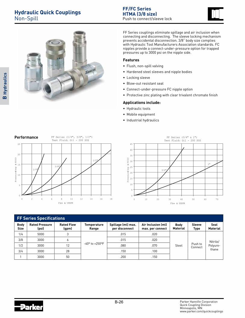
FF Series couplings eliminate spillage and air inclusion when connecting and disconnecting. The sleeve locking mechanism prevents accidental disconnection. 3/8“ body size complies with Hydraulic Tool Manufacturers Association standards. FC nipples provide a connect-under-pressure option for trapped pressures up to 3000 psi on the nipple side.
Features• Flush, non-spill valving
• Hardened steel sleeves and nipple bodies
• Locking sleeve
• Blow-out resistant seal
• Connect-under-pressure FC nipple option
• Protective zinc plating with clear trivalent chromate finish
Applications include:• Hydraulic tools
• Mobile equipment
• Industrial hydraulics
FF Series (1/4", 3/8", 1/2")Test Fluid: Oil - 200 SUS
0
5
10
15
20
25
0 2 4 6 8 10 12 14 16 18Flow in USGPM
Pre
ssur
e Drop
in PSID
1/4"3/8"
1/2"
Performance FF Series (3/4" & 1")Test Fluid: Oil - 200 SUS
0
5
10
15
20
25
30
35
40
45
0 10 20 30 40 50 60 70
Flow in USGPM
Pre
ssur
e Drop
in PSID
3/4"
1"
FF Series Specifications Body Size
Rated Pressure (psi)
Rated Flow (gpm)
Temperature Range
Spillage (ml) max. per disconnect
Air Inclusion (ml)max. per connect
Body Material
Sleeve Type
Seal Material
1/4 5000 3
-40º to +250ºF
.015 .020
Steel Push to Connect
Nitrile/Polyure-
thane
3/8 3000 6 .015 .020
1/2 3000 12 .080 .070
3/4 3000 28 .150 .100
1 3000 50 .200 .150
Hydraulic Quick Couplings Non-Spill

B-27
FF Series Couplers
Body Size
CouplerPart Number Port End Length Largest
Diameter Wrench Flats Weight (lbs.)
1/4 FF-251-4FP 1/4-18 NPSF 1.79 1.06 1.00 0.23
1/4 FF-251-4MP 1/4-18 NPTF 1.84 1.06 1.00 0.24
1/4 FF-251-6FO 9/16-18 UNF 1.91 1.06 1.00 0.23
3/8 FF-371-6FP 3/8-18 NPSF 2.39 1.20 1.06 0.44
3/8 FF-371-8FP 1/2-14 NPSF 2.80 1.20 1.06 0.50
3/8 FF-371-6FB G3/8 BSPP 2.45 1.20 1.06 0.45
3/8 FF-371-8FB G1/2 BSPP 2.80 1.20 1.06 0.48
3/8 FF-371-8FO 3/4-16 UNF 2.82 1.20 1.06 0.52
1/2 FF-501-8FP 1/2-14 NPSF 3.00 1.54 1.25 0.88
1/2 FF-501-10FO 7/8-14 UNF 3.00 1.54 1.25 1.05
3/4 FF-751-12FP 3/4-14 NPSF 3.50 1.94 1.75 1.84
3/4 FF-751-12FO 1 1/16-12 UNF 3.75 1.94 1.75 1.93
1 FF-1001-16FP 1-11 1/2NPSF 4.14 2.25 1.87 2.64
1 FF-1001-16FO 1 5/16-12UNF 4.24 2.25 1.87 2.68
FF Series Nipples
Body Size
NipplePart Number Port End Length Exposed
Length*Largest
Diameter Wrench Flats Weight (lbs.)
1/4 FF-252-4FP 1/4-18 NPSF 1.66 1.15 1.06 1.00 0.16
1/4 FF-252-4MP 1/4-18 NPTF 1.72 1.18 1.06 1.00 0.26
1/4 FF-252-6FO 9/16-18 UNF 1.66 1.15 1.06 1.00 0.16
3/8 FF-372-6FP 3/8-18 NPSF 2.31 1.71 1.08 0.94 0.26
3/8 FF-372-8FP 1/2-14 NPSF 2.64 2.04 1.19 1.06 0.32
3/8 FF-372-6FB G3/8 BSPP 2.45 1.86 1.08 0.94 0.28
3/8 FF-372-8FB G1/2 BSPP 2.70 2.16 1.19 1.06 0.32
3/8 FF-372-8FO 3/4-16 UNF 2.70 2.16 1.19 1.06 0.3
1/2 FF-502-8FP 1/2-14 NPSF 2.75 2.11 1.38 1.25 0.42
1/2 FF-502-10FO 7/8-14 UNF 2.75 2.07 1.38 1.25 0.44
3/4 FF-752-12FP 3/4-14 NPSF 3.38 2.47 1.73 1.50 1.00
3/4 FF-752-12FO 1 1/16-12 UNF 3.58 2.47 1.73 1.50 1.02
1 FF-1002-16FP 1-11 1/2 NPSF 3.85 2.60 2.17 1.87 1.60
1 FF-1002-16FO 1 5/16-12UNF 3.85 2.60 2.17 1.87 1.70
Standard Port Configurations: FP - Female Pipe Thread FO - Female Straight Thread MP - Male Pipe Thread FB - Female British Standard Pipe Parallel
* This dimension represents the portion of the nipple that is exposed when the nipple and coupler are connected.
Parker Hannifin CorporationQuick Coupling DivisionMinneapolis, MN www.parker.com/quickcouplings
B H
ydra
ulic
s
FF/FC SeriesHTMA (3/8 size) Push to connect/sleeve lock
Hydraulic Quick Couplings Non-Spill

B-28
FF Series Repair Kits1/4” Nipple FF-252-KIT FF-252-KIT-E4 FF-252-KIT-E5
1/4” Coupler FF-251-KIT FF-251-KIT-E4 FF-251-KIT-E5
3/8” Nipple FF-372-KIT FF-372-KIT-E4 FF-372-KIT-E5
3/8” Coupler FF-371-KIT FF-371-KIT-E4 FF-371-KIT-E5
3/4” Nipple FF-752-KIT FF-752-KIT-E4 FF-752-KIT-E5
3/4” Coupler FF-751-KIT FF-751-KIT-E4 FF-751-KIT-E5
1” Nipple FF-1002-KIT FF-1002-KIT-E4 FF-1002-KIT-E5
1” Coupler FF-1001-KIT FF-1001-KIT-E4 FF-1001-KIT-E5
Spline Tool–
FF/FS-251-TOOL
–
FF/FS-371-TOOL
–
FF/FS-751-TOOL
–
FF/FS-1001-TOOL
Parker Hannifin CorporationQuick Coupling DivisionMinneapolis, MN www.parker.com/quickcouplings
B H
ydra
ulic
sFF/FC SeriesHTMA (3/8” size)Push to connect/sleeve lock
Dust Caps - FF SeriesBody Size Dust Plug Part No. Rubber Dust Cap Part No. Rubber
1/4 FR-25 FR-25
3/8 NR-50 NR-37
1/2 FR-501 FR-502
3/4 FR-751 FR-7521 FR-1001 FR-1002
Hydraulic Quick Couplings Non-Spill
Optional seals include O-ring & Back-Up Ring, not Anti-Blow Out bonded seal. Contact QCD for availability and additional options.To select proper seal materials, see Fluid Compatibility Chart or contact QCD.
Code Description Part Number Examplesuffix -E5 Ethylene Propylene seal material (EPR) FF-501-8FP-E5suffix -E4 Fluorocarbon seal material FF-501-8FP-E4
Optional Seal Materials:(add code to part number)

B-29
FC Series Connect Under Pressure Nipples
Body Size Part Number Mating Half Port End Length Exposed
Length*Largest
DiameterWrench
Flats Weight (lbs.)
3/8 FC-372-6FP FF-371 3/8-18 NPSF 3.30 2.58 1.16 1.062 0.45
3/8 FC-372-8FO FF-371 3/4-16 UNF 3.30 2.58 1.16 1.062 0.42
3/8 FC-372-8FP FF-371 1/2-14 NPSF 3.30 2.58 1.16 1.062 0.42
1/2 FC-502-8FP FF-501 1/2-14 NPSF 3.46 2.65 1.22 1.125 0.53
1/2 FC-502-10FO FF-501 7/8-14 UNF 3.46 2.65 1.22 1.125 0.52
3/4 FC-752-12FO FF-751 1 1/16-12 UNF 4.81 3.72 1.65 1.500 1.32
3/4 FC-752-12FP FF-751 3/4-14 NPSF 4.81 3.72 1.65 1.500 1.34
Parker Hannifin CorporationQuick Coupling DivisionMinneapolis, MN www.parker.com/quickcouplings
B H
ydra
ulic
s
FF/FC SeriesHTMA (3/8” size) Connect under pressure nipple
FC Series Specifications
Body Size
Rated Pressure
(PSI)
Rated Connect-Under-
Pressure Capabilty
Rated Flow
(GPM)
Spillage (ML)
max. per discon-
nect
Air Inclusion
(ML)max. per connect
3/8 3000 3000 6 .015 .020
1/2 3000 3000 12 .020 .070
3/4 3000 1500 26 .150 .100
Connect Under Pressure OperationFC Series products operate slightly different from traditional non-spill couplings. With no pressure in the coupler and up to 3000 PSI of trapped pressure in the nipple, begin to couple the mating halves. Delay momentarily during con nec tion to allow trapped pressure to equalize with the mating half before completing the connection.
FC Series nipples provide a connect-under-pressure option for trapped pressures up to 3000 psi on the nipple side.
Features:• Connect-under-pressure nipple
• Flush, non-spill valving
• Hardened locking surface
• Blow-out resistant seal
• Protective zinc plating with clear trivalent chromate finish
Applications include:• Hydraulic tools
Performance
FC Series (3/8", 1/2", 3/4")Test Fluid: Oil - 200 SUS
0
10
20
30
40
50
60
0 5 10 15 20 25 30 35 40
Flow in USGPM
Pres
sure
Drop
in PS
ID
3/8"
1/2"
3/4"
Standard Port Configurations: FP - Female Pipe Thread FO - Female Straight Thread
* This dimension represents the portion of the nipple that is exposed when the nipple and coupler are connected.
Hydraulic Quick Couplings Non-Spill

B-30 Parker Hannifin CorporationQuick Coupling DivisionMinneapolis, MN www.parker.com/quickcouplings
B H
ydra
ulic
s
FEM Series (1/4", 3/8", 1/2")Test Fluid: Oil - 150 SUS
0
5
10
15
20
25
30
0 2 4 6 8 10 12 14 16 18
Flow in USGP M
Pres
sure
Drop
in PS
ID
1/4"
3/8"
1/2"
FEM/FEC SeriesISO 16028Push to Connect
Performance FEM Series (5/8", 3/4", 1")Test Fluid: Oil - 150 SUS
0
5
10
15
20
25
30
35
40
45
50
0 10 20 30 40 50 60 70
Flow in USGP M
Pres
sure
Drop
in PS
ID
5/8"
3/4"
1"
FEM Series Specifications Body Size
Rated Pressure (psi)
Rated Flow (gpm)
Temperature Range
Spillage (ml) max. per disconnect
Air Inclusion (ml)max. per connect
Body Material
Sleeve Type
Seal Material
1/4 4568 3
-40º to +250ºF
.015 .020
Steel Push to Connect
Nitrile/Poly-urethane
3/8 3625 6 .015 .020
1/2 3625 12 .020 .070
5/8 3625 20 .030 .070
3/4 3625 26 .150 .100
1 2900 50 .200 .150
Materials of ConstructionBody: SteelFinish: Chromium-6 Free platingValve: Flush face valvingSeal: Polyurethane or Nitrile; size dependant
FEM Series couplings meet or exceed ISO 16028 design and performance requirements. The flush valves eliminate spillage and air inclusion when connecting and disconnecting. Coupler and nipple bodies have a modular design with increased flexibility for end port options. FEC nipples provide a connect-under-pressure option for trapped residual pressure.
Features• Flush, non-spill valving
• Global interchangeability with other ISO 16028 compliant couplings
• Hardened steel sleeves and nipple bodies
• Optional locking sleeve
• Blow-out resistant seal
• Connect-under-pressure FEC nipple option
• Protective zinc plating with clear trivalent chromate finish
Applications include:• Skid loader attachments
• Hydraulic tools
Hydraulic Quick Couplings Non-Spill

B-31 Parker Hannifin CorporationQuick Coupling DivisionMinneapolis, MN www.parker.com/quickcouplings
B H
ydra
ulic
s
FEM Series Couplers
Body Size
CouplerPart Number Port End Length Largest
Diameter Wrench Flats Weight (lbs.)
1/4 FEM-251-4FP-NL 1/4-18 NPSF 1.96 1.06 1.00 0.25
1/4 FEM-251-6FO-NL 9/16-18 UNF 2.08 1.06 1.00 0.25
3/8 FEM-371-6FP-NL 3/8-18 NPSF 2.89 1.19 1.06 0.51
3/8 FEM-371-8FO-NL 3/4-16 UNF 2.89 1.19 1.06 0.51
1/2 FEM-501-8FP-NL 1/2-14 NPSF 2.96 1.54 1.25 0.93
1/2 FEM-501-8FO-NL 3/4-16 UNF 2.96 1.54 1.25 0.93
1/2 FEM-501-10FO-NL 7/8-14 UNF 2.96 1.54 1.25 0.93
1/2 FEM-501-12FO-NL 1 1/16-12 UNF 3.21 1.54 1.25 0.93
5/8 FEM-621-12FO-NL 1 1/16-12 UNF 3.70 1.70 1.50 1.40
3/4 FEM-751-12FP-NL 3/4-14 NPSF 3.95 1.95 1.75 2.04
3/4 FEM-751-12FO-NL 1 1/16-12 UNF 3.95 1.95 1.75 2.04
1 FEM-1001-16FP-NL 1-11 1/2-NPSF 4.21 2.25 2.00 2.70
1 FEM-1001-16FO-NL 1 5/16-12 UNF 4.21 2.25 2.00 2.70
FEM Series Couplers (Bulkhead)
Body Size
CouplerPart Number Port End Length Largest
Diameter Wrench Flats Weight (lbs.)
1/2 FEM-501-10BMF-NL 7/8-14 UNF 4.04 1.54 1.25 0.931/2 FEM-501-10BMS-NL 1-14 UNS 4.04 1.54 1.25 0.95
FEM/FEC Series ISO 16028 Push to Connect
Hydraulic Quick Couplings Non-Spill
Optional seals include O-ring & Back-Up Ring, not Anti-Blow Out bonded seal. Contact QCD for availability and additional options.To select proper seal materials, see Fluid Compatibility Chart or contact QCD.
Code Description Part Number Examplesuffix -E5 Ethylene Propylene seal material (EPR) FEM-501-8FP-NL-E5suffix -E4 Fluorocarbon seal material FEM-501-8FP-NL-E4

B-32 Parker Hannifin CorporationQuick Coupling DivisionMinneapolis, MN www.parker.com/quickcouplings
B H
ydra
ulic
s
FEM Series Nipples
Body Size
NipplePart Number Port End Length Exposed
Length*Largest
Diameter Wrench Flats Weight (lbs.)
1/4 FEM-252-4FP 1/4-18 NPSF 1.71 1.25 1.06 1.00 0.17
3/8 FEM-372-6FP 3/8-18 NPSF 2.48 1.83 1.16 1.06 0.32
3/8 FEM-372-8FO 3/4-16 UNF 2.48 1.83 1.16 1.06 0.32
1/2 FEM-502-8FP 1/2-14 NPSF 2.77 2.15 1.38 1.25 0.54
1/2 FEM-502-10FO 7/8-14 UNF 2.77 2.15 1.38 1.25 0.54
1/2 FEM-502-12FO 1 1/16-12 UN 3.02 2.35 1.38 1.25 0.54
5/8 FEM-622-12FO 1 1/16-12 UN 3.09 2.39 1.65 1.50 0.76
3/4 FEM-752-12FP 3/4-14 NPSF 3.38 2.46 1.94 1.75 1.12
3/4 FEM-752-12FO 1-1/16 12 UN 3.38 2.46 1.94 1.75 1.12
1 FEM-1002-16FP 1-11 1/2 NPSF 3.85 2.93 2.25 2.00 1.72
1 FEM-1002-16FO 1-5/16 12 UN 3.85 2.93 2.25 2.00 1.72
FEM Series Nipples (Bulkhead)
Body Size
NipplePart Number Port End Length Exposed
Length*Largest
Diameter Wrench Flats Weight (lbs.)
1/2 FEM-502-10BMF 7/8-14 UNF 3.85 3.15 1.38 1.25 0.54
1/2 FEM-502-10BMS 1-14 UNS 3.85 3.15 1.38 1.25 0.56
Dust Caps - FEM SeriesBody Size Dust Plug Part No. Rubber Dust Cap Part No. Rubber
1/4 FR-25 FR-25
3/8 NR-50 NR-37
1/2 FR-501 FER-502
3/4 FR-751 FER-7521 FR-1001 FR-1002
FEM/FEC Series ISO 16028Push to Connect
Standard Port Configurations: FP - Female Pipe Thread FO - Female Straight Thread BMF - Bulkhead Flare BMS - Bulkhead Face Seal
Other Fitting Port Configurations available upon request.
* This dimension represents the portion of the nipple that is exposed when the nipple and coupler are connected.
Hydraulic Quick Couplings Non-Spill

B-33
FEC Series Connect Under Pressure Nipples
Body Size Part Number Mating Half Port End Length Exposed
Length*Largest
DiameterWrench
Flats Weight (lbs.)
1/2 FEC-502-8FP FEM-501 1/2-14 NPSF 3.50 2.68 1.22 1.125 –
1/2 FEC-502-10FO FEM-501 7/8-14 UNF 3.50 2.68 1.22 1.125 –
1/2 FEC-502-12FO FEM-501 1 1/16-12 UNF 3.79 2.97 1.65 1.500 –
5/8 FEC-622-12FO FEM-621 1 1/16-12 UN 4.19 3.39 1.65 1.500 –
3/4 FEC-752-12FO FEM-751 1 1/16-12 UN 4.84 3.76 1.65 1.500 –
Parker Hannifin CorporationQuick Coupling DivisionMinneapolis, MN www.parker.com/quickcouplings
B H
ydra
ulic
s
FEM Series Nipples
Body Size
NipplePart Number Port End Length Exposed
Length*Largest
Diameter Wrench Flats Weight (lbs.)
1/4 FEM-252-4FP 1/4-18 NPSF 1.71 1.25 1.06 1.00 0.17
3/8 FEM-372-6FP 3/8-18 NPSF 2.48 1.83 1.16 1.06 0.32
3/8 FEM-372-8FO 3/4-16 UNF 2.48 1.83 1.16 1.06 0.32
1/2 FEM-502-8FP 1/2-14 NPSF 2.77 2.15 1.38 1.25 0.54
1/2 FEM-502-10FO 7/8-14 UNF 2.77 2.15 1.38 1.25 0.54
1/2 FEM-502-12FO 1 1/16-12 UN 3.02 2.35 1.38 1.25 0.54
5/8 FEM-622-12FO 1 1/16-12 UN 3.09 2.39 1.65 1.50 0.76
3/4 FEM-752-12FP 3/4-14 NPSF 3.38 2.46 1.94 1.75 1.12
3/4 FEM-752-12FO 1-1/16 12 UN 3.38 2.46 1.94 1.75 1.12
1 FEM-1002-16FP 1-11 1/2 NPSF 3.85 2.93 2.25 2.00 1.72
1 FEM-1002-16FO 1-5/16 12 UN 3.85 2.93 2.25 2.00 1.72
FEM/FEC SeriesISO 16028 Connect under pressure nipple
Applications
Parker FEC Series nipple provide connect-under-pressure capability with up to 3000 PSI of trapped pressure in the nipple and are ideal for ap pli ca tions where residual pressure makes reconnect difficult. Utilized primarily in the con struc tion equipment market, FEC Series products are commonly found on hydraulic attachments used in skid steer applications. The FEC Series mates with the FEM Series interface ISO 16028 couplers.
Features:• Connect-Under-Pressure nipple
• Hardened locking surface
• Steel construction, Chromium-6 Free plating for corrosion resistance
• Anti blowout bonded nipple seal
• Flush face valving
PerformanceConnect Under Pressure Operation
FEC Series products operate slightly different from traditional non-spill couplings. With no pressure in the coupler and up to 3000 PSI of trapped pressure in the nipple, begin to couple the mating halves. Delay momentarily during con nec tion to allow trapped pressure to equalize with the mating half before completing the connection.
FEC Series (1/2", 5/8", 3/4")Test Fluid: Oil - 200 SUS
0
10
20
30
40
50
60
70
80
0 10 20 30 40
Flow in USGPM
Pre
ssur
e D
rop
in P
SID
1/2"
5/8"
3/4"
FEC Series Specifications
Body Size
Rate Pressure
(psi)
Rated Connect-Under-Pressure
Capabilty
Rated Flow
(gpm)
Spillage (ml)
max. per disconnect
Air Inclusion (ml)
max. per connect
1/2 3625 3000 12 .020 .070
5/8 3625 1700 20 .003 .070
3/4 3625 1500 26 .150 .100
Standard Port Configurations: FP - Female Pipe Thread FO - Female Straight Thread
* This dimension represents the portion of the nipple that is exposed when the nipple and coupler are connected.
Hydraulic Quick Couplings Non-Spill

B-34
Optional seals include O-ring & Back-Up Ring, not Anti-Blow Out bonded seal. Contact QCD for availability and additional options.To select proper seal materials, see Fluid Compatibility Chart or contact QCD.
Code Description Part Number Examplesuffix -E5 Ethylene Propylene seal material (EPR) FH-371-6FP-E5suffix -E4 Fluorocarbon seal material FH-371-6FP-E4
Optional Seal Materials:(add code to part number)
Parker Hannifin CorporationQuick Coupling DivisionMinneapolis, MN www.parker.com/quickcouplings
B H
ydra
ulic
s
Performance FH Series (3/8")Test Fluid: Oil - 200 SUS
0
5
10
15
20
25
30
35
40
45
0 1 2 3 4 5 6 7 8 9
Flow in USGPM
Pressure Drop
in PS
ID
3/8"
FH SeriesHTMA (High Pressure)Push-to-connect/sleeve lock
FH Series high pressure, non-spill couplings have flush valves and are designed to minimize spillage and air inclusion when connecting or disconnecting. Couplers and nipples are steel with nitrile seals. Available in 3/8 inch size only, with red finish for easy identification. Will not connect with lower pressure flush face couplings.
Features:
• Rated pressure up to 10,000 psi
• Push to connect operation
• Red finish on nipple body and coupler sleeve
• Standard sleeve lock guards against accidental disconnection
• Not interchangeable with lower pressure flush face couplings
• Standard end configurations include female pipe, male pipe, and BSPP threads
• Alternative seal materials available
Applications:
• Hydraulic crimpers, cutters, benders, clamps, wedges
• Rescue equipment
• High pressure test equipment
Specifications Body Size 3/8
Rated Pressure (PSI) 10,000
Rated Flow (GPM) 6
Tem per a ture Range -40° to +250° F
Spillage (ML)(max. per disconnect) .020
Air Inclusion (ML)(max. per connect) .070
Materials of Construction Body Steel
Finish Chromium-6 Free plating
Valve Flush Face Valves
Seal Anti blow-out Nitrile/PTFE bonded seal (nipple only)
Hydraulic Quick Couplings Non-Spill

B-35
FH Series Dust Caps and Plugs
Body Size Dust Plug Rubber Dust Cap Rubber
3/8 NR-50 NR-37
Parker Hannifin CorporationQuick Coupling DivisionMinneapolis, MN www.parker.com/quickcouplings
B H
ydra
ulic
s
Nipples
Body Size
Part NumberSteel Thread Size Length Largest Diameter Wrench Flats Weight (lbs.)
3/8 FH-372-6FP 3/8-18 NPTF 2.12 1.23 1.00 0.26
3/8 FH-372-6FB G3/8 -BSPP 2.12 1.23 1.00 0.28
Couplers
Body Size
Part NumberSteel Thread Size Length Largest Diameter Wrench Flats Weight (lbs.)
3/8 FH-371-6FP 3/8 -18 NPTF 2.63 1.23 1.12 0.44
3/8 FH-371-6MP 3/8 -18 NPTF 2.85 1.23 1.12 0.45
3/8 FH-371-6FB G3/8 -BSPP 2.63 1.23 1.12 0.45
FH SeriesHTMA (High Pressure)Push-to-connect/sleeve lock
Hydraulic Quick Couplings Non-Spill
Standard Port Configurations: FP - Female Pipe Thread MP - Male Pipe Thread FB - Female British Parallel Pipe
B-36
Code Description Part Number Examplesuffix -E5 Ethylene Propylene seal material- EPR) FS-371-6FP-E5suffix -E12 Neoprene seal material FS-371-6FP-E12
Optional Seal Materials:
Parker Hannifin CorporationQuick Coupling DivisionMinneapolis, MN www.parker.com/quickcouplings
B H
ydra
ulic
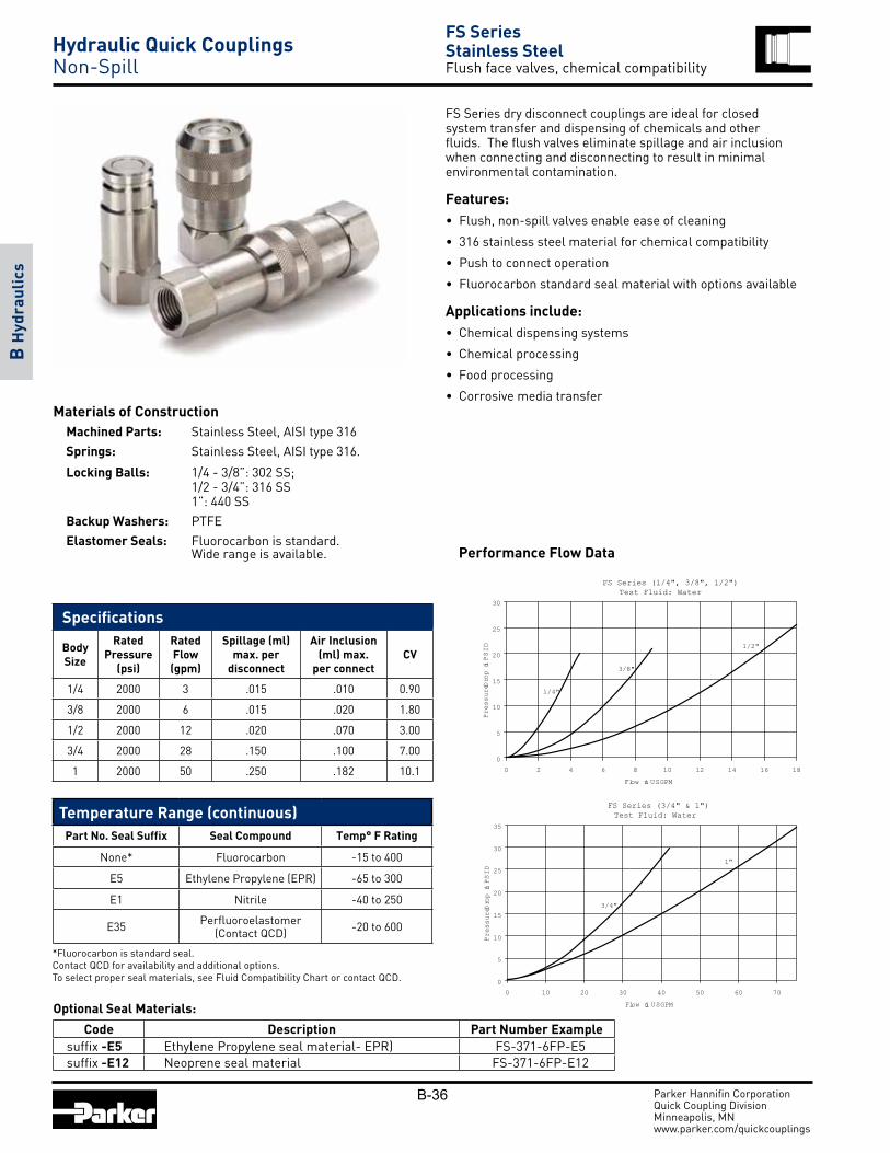
sFS SeriesStainless SteelFlush face valves, chemical compatibility
FS Series dry disconnect couplings are ideal for closed system transfer and dispensing of chemicals and other fluids. The flush valves eliminate spillage and air inclusion when connecting and disconnecting to result in minimal environmental contamination.
Features:• Flush, non-spill valves enable ease of cleaning
• 316 stainless steel material for chemical compatibility
• Push to connect operation
• Fluorocarbon standard seal material with options available
Applications include:• Chemical dispensing systems
• Chemical processing
• Food processing
• Corrosive media transferMaterials of Construction
Machined Parts: Stainless Steel, AISI type 316Springs: Stainless Steel, AISI type 316.
Locking Balls: 1/4 - 3/8”: 302 SS; 1/2 - 3/4”: 316 SS 1”: 440 SSBackup Washers: PTFEElastomer Seals: Fluorocarbon is standard. Wide range is available. Performance Flow Data
FS Series (3/4" & 1")Test Fluid: Water
0
5
10
15
20
25
30
35
0 10 20 30 40 50 60 70Flow in USGPM
Pres
sure
Drop
in PS
ID
3/4"
1"
Specifications
Body Size
Rated Pressure
(psi)
Rated Flow
(gpm)
Spillage (ml)max. per
disconnect
Air Inclusion (ml) max.
per connectCV
1/4 2000 3 .015 .010 0.90
3/8 2000 6 .015 .020 1.80
1/2 2000 12 .020 .070 3.00
3/4 2000 28 .150 .100 7.00
1 2000 50 .250 .182 10.1
Temperature Range (continuous)Part No. Seal Suffix Seal Compound Temp° F Rating
None* Fluorocarbon -15 to 400
E5 Ethylene Propylene (EPR) -65 to 300
E1 Nitrile -40 to 250
E35 Perfluoroelastomer (Contact QCD) -20 to 600
FS Series (1/4", 3/8", 1/2")Test Fluid: Water
0
5
10
15
20
25
30
0 2 4 6 8 10 12 14 16 18Flow in USGPM
Pres
sure
Drop
in PS
ID
1/4"
3/8"
1/2"
Hydraulic Quick Couplings Non-Spill
*Fluorocarbon is standard seal.Contact QCD for availability and additional options.To select proper seal materials, see Fluid Compatibility Chart or contact QCD.

B-37 Parker Hannifin CorporationQuick Coupling DivisionMinneapolis, MN www.parker.com/quickcouplings
B H
ydra
ulic
s
FS SeriesStainless SteelFlush face valves, chemical compatibility
FS Series Couplers - Female Thread
Body Size
CouplerPart Number Port End Length Largest
Diameter Wrench Flats Weight (lbs.)
1/4 FS-251-4FP 1/4-18 NPT 1.79 1.06 1.00 0.25
1/4 FS-251-4MP 1/4-18 NPTF 2.00 1.06 1.00 0.25
1/4 FS-251-6FO 9/16-18UNF 1.92 1.06 1.00 0.24
3/8 FS-371-6FP 3/8-18 NPT 2.52 1.30 1.06 0.58
3/8 FS-371-8FO 3/4-16 UNF 2.83 1.30 1.06 0.63
1/2 FS-501-8FP 1/2-14 NPT 2.74 1.58 1.38 0.92
1/2 FS-501-10FO 7/8-14 UNF 2.86 1.58 1.38 0.96
3/4 FS-751-12FP 3/4-14 NPT 3.63 1.99 1.75 2.00
3/4 FS-751-12FO 1-1/16-12 UNF 3.73 1.99 1.75 2.04
1 FS-1001-16FP 1-11 1/2 NPT 4.14 2.25 1.87 2.76
1 FS-1001-16FO 1-5/16-12 UNF 4.24 2.25 1.87 2.80
FS Series Nipples - Female Thread
Body Size
CouplerPart Number Port End Overall Length Exposed
Length*Largest
Diameter Wrench Flats Weight (lbs.)
1/4 FS-252-4FP 1/4-18 NPT 1.66 1.14 1.06 1.00 0.18
1/4 FS-252-4MP 1/4-18 NPTF 1.87 1.34 1.06 1.00 0.18
1/4 FS-252-6FO 9/16-18 UNF 1.78 1.26 1.06 1.00 0.17
3/8 FS-372-6FP 3/8-18 NPT 2.31 1.71 1.08 0.94 0.26
3/8 FS-372-8FO 3/4-16 UNF 2.45 1.71 1.19 1.06 0.30
1/2 FS-502-8FP 1/2-14 NPT 2.75 2.03 1.30 1.12 0.44
1/2 FS-502-10FO 7/8-14 UNF 2.85 2.11 1.30 1.12 0.48
3/4 FS-752-12FP 3/4-14 NPT 3.38 2.37 1.65 1.50 1.02
3/4 FS-752-12FO 1-1/16-12 UNF 3.38 2.37 1.65 1.50 1.02
1 FS-1002-16FP 1-11 1/2 NPT 3.89 2.60 2.17 1.87 1.60
1 FS-1002-16FO 1-5/16 12 UNF 3.89 2.51 2.17 1.87 1.64
Standard Port Configurations: FP - Female Pipe Thread MP - Male Pipe Thread FO - Female Straight Thread
* This dimension represents the portion of the nipple that is exposed when the nipple and coupler are connected.
Dust Caps - FS SeriesBody Size Dust Plug Part No. Rubber Dust Cap Part No. Rubber
1/4 FR-25 FR-25
3/8 NR-50 NR-37
1/2 FR-501 FR-502
3/4 FR-751 FR-7521 FR-1001 FR-1002
Hydraulic Quick Couplings Non-Spill

B-38 Parker Hannifin CorporationQuick Coupling DivisionMinneapolis, MN www.parker.com/quickcouplings
B H
ydra
ulic
sFS SeriesStainless SteelFlush face valves, chemical compatibility
FS Repair Kits
TOOL Spline tool for Coupler Repair
Replacement Seals
No Suffix Fluorocarbon Seals
E5 Eth yl ene Propylene (EPR)
E35 Perfluoroelastomer (Contact Factory for Seal Options).
FS Series Repair Kits Repair kits are available for both coupler and nipple half of FS coupling. Kits include replacement elastomer seals, valve assembly and instructions to perform rebuild. Spline tool must be ordered separately to accomplish coupler half repair. Other tools required: Vise, Allen Wrench and Open End Wrench.
Nipple Repair Kits1/4 FS-252-KIT FS-252-KIT-E5
3/8 FS-372-KIT FS-372-KIT-E5
1/2 FS-502-KIT FS-502-KIT-E5
3/4 FS-752-KIT FS-752-KIT-E5
1 FS-1002-KIT FS-1002-KIT-E5
Coupler Repair Kits1/4 N/A N/A
3/8 FS-371-KIT FS-371-E5
1/2 FS-501-KIT FS-501-KIT-E5
3/4 FS-751-KIT FS-751-KIT-E5
1 FS-1001-KIT FS-1001-KIT-E5
Hydraulic Quick Couplings Non-Spill
Spline ToolN/A
FF/FS-371-TOOL
FS-501-TOOL
FF/FS-751-TOOL
FF/FS-751-TOOL

B-39 Parker Hannifin CorporationQuick Coupling DivisionMinneapolis, MN www.parker.com/quickcouplings
B H
ydra
ulic
s
Performance 6100 Series (1/2" & 3/4")Test Fluid: OIL 150 SUS
0
10
20
30
40
50
60
70
80
90
100
0 5 10 15 20 25 30 35 40
Flow in USGPM
Pres
sure
Drop
in PS
ID
1/2"
3/4"
* Not recommended for continuous hydraulic impulse applications at rated pressures.
6100 Series (1", 1-1/4", 1-1/2")Test Fluid: OIL 150 SUS
0
10
20
30
40
50
60
70
0 10 20 30 40 50 60 70 80 90 100 110 120 130 140 150
Flow in USGPM
Pres
sure
Drop
in PS
ID
1-1/2"
1-1/4"
1"
6100 SeriesThreaded ConnectionFlush valves, high flow
6100 Series is a thread to connect, low spill coupling that can be connected under pressure. Coupler and nipple bodies are corrosion resistant brass. Couplers are available with a steel hex nut or heavy duty wing nut sleeve. A connection indicator groove on the nipple body indicates when the connection is complete and the valves are fully open.
Features:
• Rated pressures up to 3000 psi
• Thread to connect operation
• Bonded valve seal stays in place under full pressure connect and disconnect
• Visual connection indicator
• Rugged wing nut sleeve will withstand hammering to tighten or loosen
• Optional flange for secure bulkhead mounting
• Standard end configuration is female pipe thread
• Special part numbers apply for CO2 transfer (contact QCD)
Applications:
• Submersible pumps
• Oil field equipment
• Dump trailers
• Engine test stands
• Bulk liquid transfer
Specifications Body Size 3/4 3/4 1 1 - 1/4 1 - 1/2
Dash Number -08 -12 -16 -20 -24
Rated Pressure (psi) *
Female Half 3,000 3,000 3,000 2,750 2,000
Male Half 3,000 3,000 3,000 2,500 2,500
Complete Coupling Assembly 3,000 3,000 3,000 2,750 2,500
Rated Flow (gpm) 12 28 50 76 100
Temperature Range (std seals) -40° to +250°F
Hydraulic Quick Couplings Connect Under Pressure

B-40 Parker Hannifin CorporationQuick Coupling DivisionMinneapolis, MN www.parker.com/quickcouplings
B H
ydra
ulic
s
Dust Plugs for CouplersBody Size Dust Plug - Couplers
3/4 6109-08 1 6109-16
1 1/4 6109-20
1 1/2 6109-24
Coupling Set with Hex Nut
Body Size
Part NumberWith Flange
Part NumberWithout Flange
Thread Size
Overall Connected Length Weight (lbs.)
3/4 6110-08 6130-08 1/2-14 NPTF 5.20 1.89
3/4 6110-12 6130-12 3/4-14 NPTF 5.20 1.83
1 6110-16 6130-16 1-11 1/2 NPTF 5.99 2.93
1 1/4 6110-20 6130-20 1 1/4-11 1/2 NPTF 6.33 4.12
1 1/2 6110-24 6130-24 1 1/2-11 1/2 NPTF 6.55 5.95
Coupling Set with Wingnut
Body Size
Part NumberWith Flange
Part NumberWithout Flange
Thread Size
Overall Connected Length Weight (lbs.)
3/4 6100-08 6120-08 1/2-14 NPTF 5.20 2.12
3/4 6100-12 6120-12 3/4-14 NPTF 5.32 2.00
1 6100-16 6120-16 1-11 1/2 NPTF 5.99 3.19
1 1/4 6100-20 6120-20 1 1/4-11 1/2 NPTF 6.48 4.25
1 1/2 6100-24 6120-24 1 1/2-11 1/2 NPTF 6.80 6.13
6100 SeriesThreaded ConnectionFlush valves, high flow
Hydraulic Quick Couplings Connect Under Pressure
Dust Caps for NipplesBody Size Dust Cap - Nipples
3/4 6108-08 1 6108-16
1 1/4 6108-20
1 1/2 6108-24
Contact QCD for availability and additional options.To select proper seal materials, see Fluid Compatibility Chart or contact QCD.
Code Description Part Number Examplesuffix W Ethylene Propylene seal material- EPR 6135-08Wsuffix Y Fluorocarbon seal material 6135-08Ysuffix Z Neoprene seal material 6135-08Z
Optional Seal Materials:(add code to part number)

B-41 Parker Hannifin CorporationQuick Coupling DivisionMinneapolis, MN www.parker.com/quickcouplings
B H
ydra
ulic
s
Couplers - Wingnut
Body Size
Part NumberBrass Thread Size Overall Length Wrench Flats Wing Nut Weight (lbs.)
3/4 6125-08 1/2-14 NPTF 3.22 1.16 4.06 1.30
3/4 6125-12 3/4-14 NPTF 3.22 1.16 4.06 1.26
1 6125-16 1-11 1/2 NPTF 3.87 1.43 4.38 1.96
1 1/4 6125-20 1 1/4-11 1/2 NPTF 4.16 1.78 5.20 2.84
1 1/2 6125-24 1 1/2-11 1/2 NPTF 4.34 2.00 5.32 3.72
Couplers - Hex Nut
Body Size
Part NumberBrass Thread Size Overall Length Wrench Flats Hex Size Weight (lbs.)
3/4 6135-08 1/2-14 NPTF 3.22 1.16 1.75 1.07
3/4 6135-12 3/4-14 NPTF 3.22 1.16 1.75 1.07
1 6135-16 1-11 1/2 NPTF 3.87 1.43 2.13 1.89
1 1/4 6135-20 1 1/4-11 1/2 NPTF 4.16 1.78 2.50 2.56
1 1/2 6135-24 1 1/2-11 1/2 NPTF 4.34 2.00 2.75 3.15
6100 SeriesThreaded ConnectionFlush valves, high flow
Hydraulic Quick Couplings Connect Under Pressure
Nipples
Body Size
Part NumberWithout Flange
Brass
Part NumberWith Flange
BrassThread Size Overall Length Wrench Flats Hex Size Weight (lbs.)
3/4 6105-08 6115-08 1/2-14 NPTF 3.11 1.18 1.62 0.75
3/4 6105-12 6115-12 3/4-14 NPTF 3.23 1.18 1.62 0.76
1 6105-16 6115-16 1-11 1/2 NPTF 3.55 1.56 1.88 1.30
1 1/4 6105-20 6115-20 1 1/4-11 1/2 NPTF 3.71 1.88 2.13 1.65
1 1/2 6105-24 6115-24 1 1/2-11 1/2 NPTF 4.12 2.18 2.50 2.61
FlangesBody Size
Part Number Steel
Bolt Hole Diameter
Bolt Circle Diameter
3/4 6107-08 (1 piece) .208 2.13
1 6107-16 (1 piece) .208 2.38
1 1/4 6107-20 (2 piece) .208 2.63
1 1/2 6107-24 (2 piece) .281 3.25

B-42
Parker’s 8200 Series unique valve design allows connection while either or both the coupler and nipple are under pressure. Valves in both halves remain closed, opening only when system pressure has been relieved on the female body and then reapplied. This pressure sequence may be done with either an open center or a closed center hydraulic system that has a control valve.
Features:• Accepts ISO 5675 universal tips
• Connect under system pressure on the coupler side and residual pressure on the nipple side
• Sleeve designed to accommodate bracket mounting
• One-handed push-to-connect operation when coupler is clamp mounted
• 1/2” body size couplers are compatible with 5001-4 and 5006-4 breakaway clamps
• Critical parts are hardened
• Protective zinc plating with clear trivalent chromate finish
Applications include:• Tractors
• Mid-sized agricultural equipment
• Agricultural attachments requiring breakaway
Performance 8200 Series (1/2")Test Fluid: Oil - 200 SUS
0
10
20
30
40
50
60
70
0 2 4 6 8 10 12 14 16 18
Flow in USGPM
Pres
sure
Drop
in PS
ID
1/2"
8200 Series SpecificationsBody Size Rated Flow Rated Pressure Temperature Body Material Sleeve Type Seal Material
1/2 12 gpm 3000 psi -40° F to +250° F Steel Push/pull/break away Nitrile
Parker Hannifin CorporationQuick Coupling DivisionMinneapolis, MN www.parker.com/quickcouplings
B H
ydra
ulic
s8200 SeriesPush/Pull/Breakaway SleeveAccepts ISO 5675 nipples
Hydraulic Quick Couplings Connect Under Pressure
Contact QCD for availability and additional options.To select proper seal materials, see Fluid Compatibility Chart or contact QCD.
Code Description Part Number Examplesuffix W Ethylene Propylene seal material- EPR (Couplers) 8250-15Wsuffix Y Fluorocarbon seal material (Couplers) 8250-15Ysuffix Z Neoprene seal material (Couplers) 8250-15Z
Optional Seal Materials:(add code to part number)

B-43
8010 Series Nipples - Female Thread
Body Size
NipplePart Number Port End Valve Type Length Largest
Diameter Wrench Flats Weight (lbs.) Complete Coupling Part Number
1/2 8010-4 1/2-14 NPTF Ball 1.95 1.23 1.06 0.20 8200-4
1/2 8010-4P 1/2-14 NPTF Poppet 1.95 1.23 1.06 0.20 -
1/2 8010-15 3/4 -16 ORB Ball 1.95 1.23 1.06 0.20 8200-15
1/2 8010-15P 3/4 -16 ORB Poppet 1.95 1.23 1.06 0.20 -
1/2 8010-16 7/8 -14 ORB Ball 1.95 1.23 1.06 0.25 8200-16
1/2 8010-16P 7/8 -14 ORB Poppet 1.95 1.23 1.06 0.25 -
8200 Series Couplers - Female Thread
Body Size
CouplerPart Number Port End Valve Type Length Largest
Diameter Wrench Flats Weight (lbs.) Complete Coupling Part Number
1/2 8250-4 1/2-14 NPSF Poppet 3.29 1.50 0.87 0.63 8200-4
1/2 8250-15 3/4-16 ORB Poppet 3.29 1.50 0.87 0.63 8200-15
1/2 8250-16 7/8-14 ORB Poppet 3.29 1.50 0.87 0.63 8200-16
8200 Series Replacement Parts Body Size Part Number Description Material
1/2 50005-211-0200 O-Ring Nitrile
8200 Series Dust Caps and Plugs
Body Size Dust Cap Color/Material Dust Plug Weight
(lbs.)
1/2 5205-4M Black Rubber 5209-4M .04
1/2 5005-4 Steel w/Chain 5009-4 .21
1/2 5205-4M-BU Blue Rubber 5209-4M-BU .04
1/2 5205-4M-GR Green Rubber 5209-4M-GR .04
1/2 5205-4M-RE Red Rubber 5209-4M-RE .04
1/2 5205-4M-YE Yellow Rubber 5209-4M-YE .04
Parker Hannifin CorporationQuick Coupling DivisionMinneapolis, MN www.parker.com/quickcouplings
B H
ydra
ulic
s
8200 SeriesPush/Pull/BreakawayAccepts ISO 5675 nipples
Hydraulic Quick Couplings Connect Under Pressure

B-44
9200 Series Specifications:Body Size Rated Flow Rated Pressure Temperature Body Material Sleeve Type Seal Material
1/2 12 gpm 3000 psi -40° F to +250° F Steel Push/pull/breakaway Nitrile
The 9200 Series coupler allows zero pressure connection and disconnection while either or both the coupler and nipple are under pressure. A lever operated cam locks both coupler and nipple valves in the open or closed position. “Closed”, the flow is shut off at the coupler, allowing easy connect and disconnect. Valves in the “Open” position are locked in place and unaffected by hydraulic surges. Valves will automatically close if the coupling is accidentally disconnected.
Features:• Accepts ISO 5675 universal tips
• Premier connect under pressure coupling
• Locked valves prevent flow checking
• Functionally can replace a double shut-off quick coupling and two high pressure ball valves
• Protective zinc plating with clear trivalent chromate finish
Applications include:• Mobile equipment
• Industrial hydraulics
• Not recommended for use with gaseous or compressible media
Performance: 9200 Series (1/2")Test Fluid: Oil - 200 SUS
0
10
20
30
40
50
60
70
80
90
0 2 4 6 8 10 12 14 16 18
Flow in USGPM
Pres
sure
Drop
in PS
ID
1/2"
Parker Hannifin CorporationQuick Coupling DivisionMinneapolis, MN www.parker.com/quickcouplings
B H
ydra
ulic
s9200 SeriesLever Actuated Accepts ISO 5675 nipples
Hydraulic Quick Couplings Connect Under Pressure
Contact QCD for availability and additional options.To select proper seal materials, see Fluid Compatibility Chart or contact QCD.
Code Description Part Number Examplesuffix W Ethylene Propylene seal material- EPR (Couplers) 9250-4-320Wsuffix Y Fluorocarbon seal material (Couplers) 9250-4-320Ysuffix Z Neoprene seal material (Couplers) 9250-4-320Z
Optional Seal Materials:(add code to part number)

B-45
9200 Series Couplers
Body Size
CouplerPart Number Port End Valve Type Orientation Length Largest
DiameterWrench
FlatsWeight (lbs.)
1/2 9250-4-320* 1/2-14 NPTF Poppet Left hand – yellow grip 5.37 1.50 1.13 1.98
1/2 9250-6-320* 9/16-18 UNF Poppet Left hand – yellow grip 5.37 1.50 1.13 2.06
1/2 9250-15-320* 3/4-16 UNF Poppet Left hand – yellow grip 5.37 1.50 1.13 2.06
1/2 9250-16-320* 7/8-14 UNF Poppet Left hand – yellow grip 5.37 1.50 1.13 2.06
1/2 9250-334** 9/16-18 UNF Poppet Left hand – yellow grip 5.37 1.50 1.13 2.15
* -320 indicates lower sleeve spring force for easier connection when coupler is not mounted in a clamp.** -334 couplers connect with ¼” ISO 7241-B series nipples.
9200 Series Replacement PartsBody Size Part Number Description Weight
(lbs.)
1/2 50001-211-0260 Interface O-Ring .01
9200 Series Dust Caps and Plugs
Body Size Coupler Dust Cover Color/Material Nipple Dust Cap Weight (lbs.)
1/2 9507-4-1 Black Rubber 5209-4M .04
* Connects with 9250-334 couplers
Parker Hannifin CorporationQuick Coupling DivisionMinneapolis, MN www.parker.com/quickcouplings
B H
ydra
ulic
s
8010 Series Nipples
Body Size
NipplePart Number Port End Valve Type Length Largest
Diameter Wrench Flats Weight(lbs.)
1/4 H2-63-T6* 9/16-18 ORB Poppet 1.54 1.01 0.88 0.10
1/2 8010-4 1/2-14 NPTF Ball 1.95 1.23 1.06 0.20
1/2 8010-4P 1/2-14 NPTF Poppet 1.95 1.23 1.06 0.20
1/2 8010-15 3/4-16 ORB Ball 1.95 1.23 1.06 0.20
1/2 8010-15P 3/4-16 ORB Poppet 1.95 1.23 1.06 0.20
1/2 8010-16 7/8-14 ORB Ball 1.95 1.23 1.06 0.25
1/2 8010-16P 7/8-14 ORB Poppet 1.95 1.23 1.06 0.25
9200 SeriesLever ActuatedAccepts ISO 5675 nipples
Hydraulic Quick Couplings Connect Under Pressure

B-46
5000 Series SpecificationsBody Size Rated Flow Rated Pressure Temperature Body Material Sleeve Type Seal Material
1/2 12 gpm 2500 psi -40° F to +250° F Steel Single Acting Nitrile
The 5000 Series is an economical coupling that can be connected under pressure where tools can be used to make the connection. The coupler and nipple are connected and then the valves are opened from tightening the threaded union on the back of the coupler body. Unscrewing the body threads will permit the valves to close and the coupler sleeve can be retracted to release the nipple.
Features:• Accepts ISO 5675 universal tips
• Manual, threaded actuation, connect under pressure coupling
• Protective zinc plating with clear trivalent chromate finish
Applications include:• Lubrication systems
• Hydraulic tools
• Attachments
Performance: 5000 Series (1/2")Test Fluid: Oil - 200 SUS
0
10
20
30
40
50
60
70
0 2 4 6 8 10 12 14 16 18
Flow in USGPM
Pressure Drop
in PS
ID
1/2"
Parker Hannifin CorporationQuick Coupling DivisionMinneapolis, MN www.parker.com/quickcouplings
B H
ydra
ulic
s5000 SeriesThreaded Actuation Accepts ISO 5675 nipples
Hydraulic Quick Couplings Connect Under Pressure
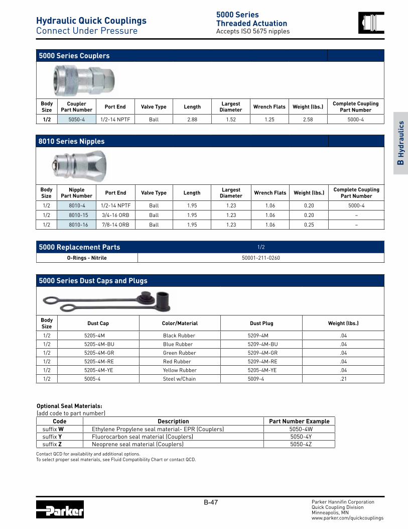
B-47
8010 Series Nipples
Body Size
NipplePart Number Port End Valve Type Length Largest
Diameter Wrench Flats Weight (lbs.) Complete Coupling Part Number
1/2 8010-4 1/2-14 NPTF Ball 1.95 1.23 1.06 0.20 5000-4
1/2 8010-15 3/4-16 ORB Ball 1.95 1.23 1.06 0.20 –
1/2 8010-16 7/8-14 ORB Ball 1.95 1.23 1.06 0.25 –
5000 Series Couplers
Body Size
CouplerPart Number Port End Valve Type Length Largest
Diameter Wrench Flats Weight (lbs.) Complete Coupling Part Number
1/2 5050-4 1/2-14 NPTF Ball 2.88 1.52 1.25 2.58 5000-4
5000 Replacement Parts 1/2
O-Rings - Nitrile 50001-211-0260
Parker Hannifin CorporationQuick Coupling DivisionMinneapolis, MN www.parker.com/quickcouplings
B H
ydra
ulic
s
5000 Series Dust Caps and Plugs
Body Size Dust Cap Color/Material Dust Plug Weight (lbs.)
1/2 5205-4M Black Rubber 5209-4M .04
1/2 5205-4M-BU Blue Rubber 5209-4M-BU .04
1/2 5205-4M-GR Green Rubber 5209-4M-GR .04
1/2 5205-4M-RE Red Rubber 5209-4M-RE .04
1/2 5205-4M-YE Yellow Rubber 5205-4M-YE .04
1/2 5005-4 Steel w/Chain 5009-4 .21
5000 SeriesThreaded ActuationAccepts ISO 5675 nipples
Hydraulic Quick Couplings Connect Under Pressure
Contact QCD for availability and additional options.To select proper seal materials, see Fluid Compatibility Chart or contact QCD.
Code Description Part Number Examplesuffix W Ethylene Propylene seal material- EPR (Couplers) 5050-4Wsuffix Y Fluorocarbon seal material (Couplers) 5050-4Ysuffix Z Neoprene seal material (Couplers) 5050-4Z
Optional Seal Materials:(add code to part number)

B-48
3000 Series (1/4", 3/8")Test Fluid: Oil - 200 SUS
0
20
40
60
80
100
120
140
160
0 1 2 3 4 5 6 7 8 9
Flow in USGPM
Pres
sure
Dro
p in
PSI
D
1/4"
3/8"
3000 Series SpecificationsBody Size Rated Flow (gpm) Rated Pressure (psi) Temperature Body Material Sleeve Type Seal Material
1/4 3 10,000 -22° F to +230° F
Steel Thread to connect Polyurethane
3/8 6 Steel Thread to connect Polyurethane
The 3000 Series coupling are designed for high pressure applications. The coupler sleeve and nipple body must be manually threaded together to make the connection.
Features:• Manual threaded connection and actuation
• Hard, chrome alloy ball valves
• Polyurethane interface seal resists high pressure extrusion
• Threaded retainer provides a positive valve stop
• Protective zinc plating with clear trivalent chromate finish
Applications include:
• Hydraulic rams
• Portable hydraulic tools
• Crimping equipment
Performance:
Parker Hannifin CorporationQuick Coupling DivisionMinneapolis, MN www.parker.com/quickcouplings
B H
ydra
ulic
s3000 SeriesThreaded ConnectionSteel body, polyurethane seal
Hydraulic Quick Couplings High Pressure

B-49
3000 Series Nipples
Body Size
NipplePart Number Port End Valve Type Length Largest
Diameter Wrench Flats Weight (lbs.)
1/4 3010-2 1/4-18 NPTF (Female) Ball 1.29 1.13 0.88 0.14
3/8 3010-3 3/8-18 NPTF (Female) Ball 1.58 1.25 0.94 0.23
3/8 3010-3-230 3/8-18 NPTF (Male) Ball 2.31 1.25 1.00 0.30
3000 Series Couplers
Body Size
CouplerPart Number Port End Valve Type Length Largest
Diameter Wrench Flats Weight (lbs.)
1/4 3050-2 1/4-18 NPTF (Male) Ball 2.38 1.13 0.81 0.25
3/8 3050-3 3/8-18 NPTF (Male) Ball 2.38 1.38 1.00 0.49
3/8 3050-3-231 3/8-18 NPTF (Female) Ball 2.38 1.38 1.00 0.49
Parker Hannifin CorporationQuick Coupling DivisionMinneapolis, MN www.parker.com/quickcouplings
B H
ydra
ulic
s
3000 SeriesThreaded ConnectionSteel body, polyurethane seal
3000 Series Dust Caps and Plugs
Body Size Dust Cap Color/Material Dust Plug Weight
(lbs.)
1/4 3009-2 Steel 3005-2 .02
3/8 3009-3 Steel 3005-3 .04
3000 Series Replacement O-Rings Body Size Material Part Number Durometer
1/4 Polyurethane 50001-114-0296 90
3/8 Polyurethane 50001-210-0296 90
Hydraulic Quick Couplings High Pressure

B-50
Coupler
Body Size Part Number Thread Size Overall Length Largest Diameter Wrench Flats Weight (lbs.)
3/8 TC-371 3/8-18 NPSF 2.48 1.25 0.94 0.43
Performance
3/8"
TC Series (3/8")Test Fluid: Oil - 200 SUS
0
10
20
30
40
50
60
70
80
90
100
0 1 2 3 4 5 6 7 8 9
Flow in USGPM
Pressure Drop
in PS
ID
TC SeriesManual SleeveSleeve lock, fluorocarbon seal
TC Series couplings are used in high pressure applications with hydraulic and mechanical shock. Steel coupler sleeves and nipple bodies are hardened for resistance to damage. Fluorocarbon seals along with PTFE back up rings provide reliable sealing in high pressures. Available in 3/8 inch size only, with sleeve lock to guard against accidental disconnection.
Features:
• Rated pressure up to 10,000 psi
• Manual sleeve operation
• Fluorocarbon seals
• Standard sleeve lock guards against accidental disconnection
• Positive valve stop prevents flow checking
• Standard end configuration is female pipe thread
• Protective zinc plating with clear trivalent chromate finish
Applications:• Hydraulic jacking and house moving equipment
• Construction equipment
• Railway maintenance
Specifications Body Size 3/8
Rated Pressure (psi) 10,000
Rated Flow (gpm) 6
Tem per a ture Range (std seals) -15° to +400° F
Nipple
Body Size Part Number Thread Size Overall Length Exposed Length Largest Diameter Wrench Flats Weight (lbs.)
3/8 TC-372 3/8-18 NPSF 1.82 0.66 1.08 0.94 0.14
TC Series Dust Plug/Caps TR-37
Parker Hannifin CorporationQuick Coupling DivisionMinneapolis, MN www.parker.com/quickcouplings
B H
ydra
ulic
s
Hydraulic Quick Couplings High Pressure
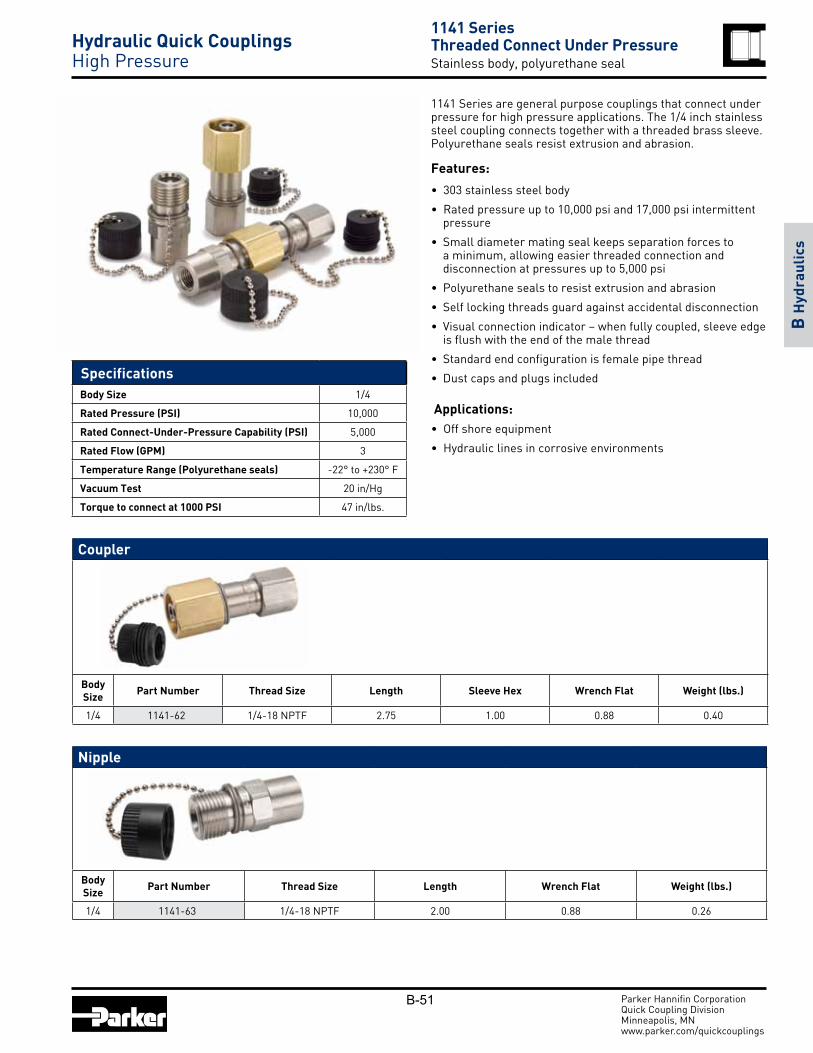
B-51
Nipple
Body Size Part Number Thread Size Length Wrench Flat Weight (lbs.)
1/4 1141-63 1/4-18 NPTF 2.00 0.88 0.26
Coupler
Body Size Part Number Thread Size Length Sleeve Hex Wrench Flat Weight (lbs.)
1/4 1141-62 1/4-18 NPTF 2.75 1.00 0.88 0.40
1141 SeriesThreaded Connect Under PressureStainless body, polyurethane seal
Hydraulic Quick Couplings High Pressure
1141 Series are general purpose couplings that connect under pressure for high pressure applications. The 1/4 inch stainless steel coupling connects together with a threaded brass sleeve. Polyurethane seals resist extrusion and abrasion.
Features:
• 303 stainless steel body
• Rated pressure up to 10,000 psi and 17,000 psi intermittent pressure
• Small diameter mating seal keeps separation forces to a minimum, allowing easier threaded connection and disconnection at pressures up to 5,000 psi
• Polyurethane seals to resist extrusion and abrasion
• Self locking threads guard against accidental disconnection
• Visual connection indicator – when fully coupled, sleeve edge is flush with the end of the male thread
• Standard end configuration is female pipe thread
• Dust caps and plugs included
Applications:• Off shore equipment
• Hydraulic lines in corrosive environments
Specifications Body Size 1/4
Rated Pressure (PSI) 10,000
Rated Connect-Under-Pressure Capability (PSI) 5,000
Rated Flow (GPM) 3
Temperature Range (Polyurethane seals) -22° to +230° F
Vacuum Test 20 in/Hg
Torque to connect at 1000 PSI 47 in/lbs.
Parker Hannifin CorporationQuick Coupling DivisionMinneapolis, MN www.parker.com/quickcouplings
B H
ydra
ulic
s

B-52 Parker Hannifin CorporationQuick Coupling DivisionMinneapolis, MN www.parker.com/quickcouplings
B H
ydra
ulic
s
ST Series non-valved couplings provide maximum flow and low pressure drop. The smooth, open bore allows easy cleaning in applications where the same lines are used for more than one media.
Features
• Steel nipples are case hardened for resistance to Brinelling
• Functionally interchanges with similar straight-through design couplings
• Standard Nitrile seals
• Material options available
• Sleeve-Lok option available
Applications:
• High pressure water
• Steam washers
• Carpet cleaners
Performance
Specifications Body Size
Rated Pressure (psi) Brass Coupler/Nipple
Rated Pressure (psi) Brass Coupler/Steel Nipple
Rated Pressure (psi) 303 SS Coupler/Nipple
Temperature Range (standard seals) Rated Flow
1/8 2500 2600 4200
-40º to +250º F
3
1/4 5200 5500 6700 6
3/8 2700 3500 5500 12
1/2 2200 2700 3000 12
3/4 1700 2700 3000 28
1 1200 2000 1700 50
1-1/4 1700 – – 76
1-1/2 1400 – – 100
ST Series (3/4", 1", 1-1/4")Test Fluid: Oil - 150 SUS
0
1
2
3
4
5
0 20 40 60 80 100
Flow in USGPM
Pres
sure
Drop
in PS
ID
3/4"
1"
1-1/4"
ST Series (1/8", 1/4", 3/8", 1/2")Test Fluid: Oil - 150 SUS
0
2
4
6
8
10
12
0 2 4 6 8 10 12 14 16 18
Flow in USGPM
Pres
sure
Drop
in PS
ID
1/8"
1/4"
3/8" 1/2"
ST SeriesStraight-through Interface Non-valved, manual sleeve
Hydraulic Quick Couplings High Flow

B-53 Parker Hannifin CorporationQuick Coupling DivisionMinneapolis, MN www.parker.com/quickcouplings
B H
ydra
ulic
s
ST Series Couplers - Male Pipe Thread
Body Size
BrassPart Number
303 StainlessPart Number Port End Length Largest
DiameterWrench
FlatsBrass
Weight (lbs.)Stainless
Weight (lbs.)
1/8 BST-1M SST-1M 1/8-27 NPTF 1.06 0.69 0.56 0.05 0.05
1/4 BST-2M SST-2M 1/4-18 NPTF 1.69 0.94 0.81 0.13 0.16
3/8 BST-3M SST-3M 3/8-18 NPTF 1.75 1.16 1.00 0.25 1.16
1/2 BST-4M SST-4M 1/2-14 NPTF 1.94 1.30 1.13 0.34 1.30
3/4 BST-6M SST-6M 3/4-14 NPTF 2.17 1.66 1.44 – 1.66
1 BST-8M SST-8M 1-11 1/2 NPTF 2.53 2.02 1.75 0.85 2.02
ST Series Couplers - Female Pipe Thread
Body Size
BrassPart Number
303 StainlessPart Number Port End Length Largest
DiameterWrench
FlatsBrass
Weight (lbs.)Stainless
Weight (lbs.)
1/8 BST-1 SST-1 1/8-27 NPTF 1.06 0.69 0.56 0.06 0.05
1/4 BST-2 SST-2 1/4-18 NPTF 1.54 0.94 0.81 0.17 0.15
3/8 BST-3 SST-3 3/8-18 NPTF 1.64 1.16 1.00 0.26 0.24
1/2 BST-4 SST-4 1/2-14 NPTF 1.98 1.30 1.13 0.40 0.37
3/4 BST-6 SST-6 3/4-14 NPTF 2.15 1.66 1.44 0.62 0.57
1 BST-8 SST-8 1-11 1/2 NPTF 2.43 2.02 1.75 0.99 0.93
1-1/4 BST-10 – 1 1/4-11 1/2 NPTF 2.44 2.51 2.00 1.38 –
1-1/2 BST-12 – 1 1/2-11 1/2 NPTF 2.88 3.00 2.50 2.43 –
ST SeriesStraight-through Interface Non-valved, manual sleeve
Hydraulic Quick Couplings High Flow
Contact QCD for availability and additional options.To select proper seal materials, see Fluid Compatibility Chart or contact QCD.
Code Description Part Number Examplesuffix -SL Sleeve-Lok (Couplers) SST-3M-SLsuffix W Ethylene Propylene seal material- EPR (Couplers) SST-3MWsuffix Y Fluorocarbon seal material (Couplers) SST-3MYsuffix Z Neoprene seal material (Couplers) SST-3MZ
Optional Materials and Features:(add code to part number)

B-54 Parker Hannifin CorporationQuick Coupling DivisionMinneapolis, MN www.parker.com/quickcouplings
B H
ydra
ulic
s
ST Series Nipples- Female Pipe Thread
Body Size
Brass Part No.
Weight. (lbs.)
Steel Part No.
Weight. (lbs.)
303 Stainless Part No.
Weight. (lbs.) Length Largest
DiameterWrench
Flats
1/8 BST-N1 0.03 ST-N1 0.03 SST-N1 0.02 0.98 0.65 0.56
1/4 BST-N2 0.07 ST-N2 0.07 SST-N2 0.07 1.46 0.87 0.75
3/8 BST-N3 0.12 ST-N3 0.11 SST-N3 0.11 1.62 1.59 0.08
1/2 BST-N4 0.23 ST-N4 0.21 SST-N4 0.21 1.85 1.30 1.13
3/4 BST-N6 0.33 ST-N6 0.32 SST-N6 0.32 2.15 1.59 1.38
1 BST-N8 0.52 ST-N8 0.49 SST-N8 0.48 2.35 1.88 1.63
1-1/4 BST-N10 0.85 – – – – 2.38 2.31 2.00
1-1/2 BST-N12 1.45 – – – – 2.81 2.74 2.38
ST SeriesStraight-through Interface Non-valved, manual sleeve
Hydraulic Quick Couplings High Flow
ST Series Nipples- Male Pipe Thread
Body Size
Brass Part No.
Weight. (lbs.)
Steel Part No.
Weight. (lbs.)
303 Stainless Part No.
Weight. (lbs.) Length Largest
DiameterWrench
Flats
1/8 BST-N1M 0.02 ST-N1M 0.02 SST-N1M 0.02 1.04 0.51 0.44
1/4 BST-N2M 0.06 ST-N2M 0.05 SST-N2M 0.05 1.53 0.65 0.56
3/8 BST-N3M 0.08 ST-N3M 0.07 SST-N3M 0.08 1.69 0.79 0.69
1/2 BST-N4M 0.15 ST-N4M 0.13 SST-N4M 0.13 1.94 1.01 0.88
3/4 BST-N6M 0.23 ST-N6M 0.21 SST-N6M 0.22 2.19 1.23 1.06
1 BST-N8M 0.46 ST-N8M 0.43 SST-N8M 0.43 2.51 1.59 1.38
1-1/4 BST-N10M 0.96 – – – – 2.85 2.17 1.88
1-1/2 BST-N12M 1.46 – – – – 3.25 2.45 2.13

B-55 Parker Hannifin CorporationQuick Coupling DivisionMinneapolis, MN www.parker.com/quickcouplings
B H
ydra
ulic
s
Parker Water Service Quick Couplings add convenience and efficiency wherever water hoses are frequently connected and disconnected. The durable 4-ball locking mechanism provides a secure connection.
Features:• Brass and stainless steel construction
• Nitrile seals
Applications include:• Garden hoses
• Wash down systems
• Mobile water tank lines
Specifications Body Size Rated Pressure (psi) Rated Flow (gpm) Temperature Range (std seals)
3/4 200 28 -40º to +250º F
Coupler
Body Size
CouplerPart Number Port End Length Largest
Diameter Weight (lbs.)
3/4 1163-60 3/4-11 1/2 NH 1.16 1.21 0.12
Nipple
Body Size
NipplePart Number Port End Overall Length Exposed Length Weight (lbs.)
3/4 1163-61 3/4-11 1/2 NH 1.25 0.50 0.08
1163 SeriesWater Hose Connectors Non-valved, manual sleeve
Hydraulic Quick Couplings High Flow

B-56
.To select proper seal materials, see Fluid Compatibility Chart or contact QCD Contact QCD for availability..
Code Description Part Number Examplesuffix -E5 Ethylene Propylene seal material- EPR (Couplers) HO-371-6FP-E5suffix -E4 Fluorocarbon seal material (Couplers) HO-371-6FP-E4suffix -E12 Neoprene seal material (Couplers) HO-371-6FP-E12
Optional Seal Materials:
Parker Hannifin CorporationQuick Coupling DivisionMinneapolis, MN www.parker.com/quickcouplings
B H
ydra
ulic
s
Couplers
Body Size Part Number Thread Size Overall Length Largest Diameter Wrench Flats Weight (lbs.) Dust Plug
Rubber
1/4 HO-251-4FP 1/4-18 NPTF 1.67 1.06 0.94 0.24 TR-37
3/8 HO-371-6FP 3/8-18 NPTF 1.67 1.06 0.94 0.22 TR-37
1/2 HO-501-8FP 1/2-14 NPTF 2.03 1.62 1.25 0.52 DP-50
HO SeriesNon-Valved, High PressureManual sleeve, sleeve lock
Hydraulic Quick Couplings High Flow
HO series couplings are high flow, high pressure, steel couplings for a wide variety of applications. Electroless nickel plating provides corrosion resistance.
Features:
• Steel material with electroless nickel plating
• Nitrile seals with PTFE back up ring
• No valving, unrestricted flow
• Standard sleeve lock guards against accidental disconnection
• Rated pressures up to 15,000 psi
Applications:
• Paper and pulp processing
• Refinery systems
• Testing systems
Specifications Body Size 1/4 3/8 1/2
Rated Pressure (PSI) 15,000 15,000 10,000
Rated Flow (GPM) 3 6 12
Temperature Range (std seals) -40° to +250°F
Nipples
Body Size Part Number Thread Size Overall Length Exposed Length Largest Diam-
eter Wrench Flats Weight (lbs.) Dust Plug Rubber
1/4 HO-252-4FP 1/4-18 NPTF 1.40 0.66 0.94 0.81 0.10 TR-37
3/8 HO-372-6FP 3/8-18 NPTF 1.44 0.70 1.08 0.94 0.12 TR-371/2 HO-502-8FP 1/2-14 NPTF 2.03 0.86 1.30 1.12 0.26 DP-50

B-57 Parker Hannifin CorporationQuick Coupling DivisionMinneapolis, MN www.parker.com/quickcouplings
B H
ydra
ulic
s
Performance
Guidelines for Selection and Use:Non-valved couplers provide maximum flow for efficient cooling. Valved couplers shut off automatically when disconnected. Valved couplers can be used with either valved or non-valved nipples. A valved nipple, however, must be used with a valved coupler.
Moldmate couplings are rated for 200 psi max pressure. Most thermoplastic and thermoset heat transfer systems have pumps which provide relatively high flow rates at low pressures. Water and water glycol systems usually have capacities ranging from 10 to 40 gpm with most from 10 to 15 gpm. Normal medial opening pressures are 20 to 60 psi for these systems. Heat transfer systems using oil gen er al ly operate from 10 to 30 psi. However, their flow rates are usually much higher, requiring the total volume of oil to be cir cu lated at least once per minute.
The number of hose connections in a single mold system results in a cu mu la tive pres sure drop. Please note the Pressure Drop vs. Flow Rate chart pro vided, to select the appropriate size.
Temperature is another important con sid era tion. Parker Moldmate couplings with the standard sili cone seal have a temperature capability of -90° to +400°F. Rapid deterioration of the seal and leakage may result if used beyond these limits.
External conditions of temperature, corrosive at mo spheres, and other ab nor mal i ties may affect coupling performance and must be considered when selection is made. Con sult QCD with questions.
Moldmate Series (1/4", 3/8", 1/2")Test Fluid: Water (Straight Coupler)
0
5
10
15
20
25
30
35
40
45
50
0 2 4 6 8 10 12 14 16 18
Flow in USGP M
Pressure Drop in PS
ID
1/4" Valved
1/4" Non-valved
3/8" Valved
3/8" Non-valved
1/2" Non-valved
Moldmate SeriesSpecial Purpose-Mold CoolantBrass body, silicone seal
Hydraulic Quick Couplings Mold Coolant
Moldmate series couplings are specifically designed for connecting coolant lines to molds and dies on injection molding machinery and die casting equipment. These couplings significantly reduce downtime, by providing a quick and easy way to connect and disconnect lines during mold changes.
Features:
• Rated pressure is 200 psi
• Valved and unvalved options. Valved couplers have silver colored sleeves
• Brass material with standard silicone interface seals are compatible with water and water glycol fluids. Valved versions have a fluorocarbon seal on the poppet.
• Optional fluorocarbon seal for use with oil based media
• Short nipples can be installed recessed below the mold surface enabling more efficient storage and protecting the nipple from damage
• Standard and Push-Lok hose barb ends are available in straight, 45 or 90 degree configurations
• Manual sleeve operation
• Extension nipples are offered in several lengths
Applications:• Mold coolant lines
• Die casting equipment
Special Order Information:
Standard seal material is Silicone and is com pat i ble with water and water glycol fluids com mon ly used in heat transfer systems. Fluorocarbon seals are available for use with oil-based media. To specify a Fluorocarbon seal, add the suffix “Y” to the standard moldmate part number, thus: PC206Y.
Specifications Body Size 1/4 3/8 1/2
Rated Pressure (psi) 200
Rated Flow (gpm) 3 6 12
* For use with oil based media only
Material Temperature Range Standard Silicone seal -20° to +400° F
*Optional Fluorocarbon seal -15° to +400° F

B-58 Parker Hannifin CorporationQuick Coupling DivisionMinneapolis, MN www.parker.com/quickcouplings
B H
ydra
ulic
s
Couplers - 45 Degree
Body Size
Part Number Brass
Non-Valved
Weight (lb.)
Part Number BrassValved
Weight (lb.)
HoseI.D.
OverallLength
Largest Diameter
WrenchFlats
OverallLength
Largest Diameter
WrenchFlats
Non-Valved Valved1/4 PC224 0.13 PC224AV 0.13 1/4 2.67 0.71 0.56 2.87 0.71 0.631/4 PC224-BP* 0.13 PC224AV-BP 0.14 1/4 2.57 0.71 0.56 2.77 0.71 0.631/4 PC226 0.13 PC226AV 0.14 3/8 2.71 0.71 0.56 2.91 0.71 0.631/4 PC226-BP* 0.26 PC226AV-BP 0.17 3/8 2.74 0.71 0.56 2.94 0.71 0.633/8 PC326 0.36 PC326V 0.36 3/8 3.65 0.96 0.88 3.65 1.01 0.883/8 PC326-BP* 0.34 PC326V-BP 0.36 3/8 3.75 0.96 0.88 3.75 1.01 0.883/8 PC328 0.36 PC328V 0.36 1/2 3.69 0.96 0.88 3.69 1.01 0.883/8 PC328-BP* 0.34 PC328V-BP 0.40 1/2 3.88 0.96 0.88 3.88 0.96 0.881/2 PC524 0.74 NA – 1/2 4.18 1.21 1.12 –1/2 PC524-BP* 0.78 NA – 1/2 4.28 1.21 1.12 –1/2 PC526 0.76 NA – 3/4 4.56 1.21 1.12 –1/2 PC526-BP* 0.80 NA – 3/4 4.56 1.21 1.12 –
Couplers - Straight
Body Size
Part Number Brass
Non-Valved
Weight (lb.)
Part Number BrassValved
Weight (lb.)
HoseI.D.
OverallLength
LargestDiameter
OverallLength
LargestDiameter
WrenchFlats
Non-Valved Valved1/4 PC204 0.10 PC204AV 0.10 1/4 1.87 0.63 2.67 0.71 0.631/4 PC204-BP* 0.10 PC204AV-BP 0.10 1/4 1.89 0.63 2.52 0.71 0.631/4 PC205 0.09 PC205AV 0.10 5/16 1.87 0.63 2.67 0.71 0.631/4 PC206 0.09 PC206AV 0.10 3/8 1.87 0.63 2.67 0.71 0.631/4 PC206-BP* 0.11 PC206AV-BP 0.13 3/8 2.04 0.63 2.70 0.71 0.633/8 PC306 0.24 PC306V 0.27 3/8 3.01 0.96 3.17 1.01 0.883/8 PC306-BP* 0.26 PC306V-BP 0.29 3/8 3.15 0.96 3.31 1.01 0.883/8 PC308 0.25 PC308V 0.28 1/2 3.15 0.96 3.17 1.01 0.883/8 PC308-BP* 0.25 PC308V-BP 0.03 1/2 3.27 0.96 3.43 1.01 0.881/2 PC504 0.46 NA – 1/2 3.55 1.30 –1/2 PC504-BP* 0.50 NA – 1/2 3.68 1.21 –1/2 PC506 0.48 NA – 3/4 3.80 1.21 –1/2 PC506-BP* 0.52 NA – 3/4 3.80 1.21 –
Standard Hose Barb
Moldmate SeriesSpecial Purpose-Mold CoolantBrass body, silicone seal
Hydraulic Quick Couplings Mold Coolant
NA = Not Available
* Suffix BP in part number denotes Push-Lok hose barb. Without suffix denotes standard hose barb. Push-Lok hose barbs are designed for use with Parker Push-Lok hose and do not require clamps. Valved Couplers can be used with either non-valved or valved nipples.
Push-Lok Hose Barb
Standard Hose BarbPush-Lok Hose Barb

B-59 Parker Hannifin CorporationQuick Coupling DivisionMinneapolis, MN www.parker.com/quickcouplings
B H
ydra
ulic
s
Non-valved Sub-assembly (Brass Sleeve)
Body Size
Part No. BrassNon-Valved Weight (lb.) Thread Size Length Largest Diameter Wrench Flats
1/4 P208-01A 0.07 1/8-27 NPTF 1.15 0.71 0.56
3/8 P308-01A 0.21 1/4-18 NPTF 1.84 0.96 0.88
3/8 P308-01A-HF 0.20 3/8-18 NPTF 1.84 0.96 0.88
1/2 PC500 0.34 1/2-14 NPTF 2.02 1.21 1.12
Couplers - 90 Degree
Body Size
Part No. BrassNon-Valved
Weight (lb.)
Part No. BrassValved (silver sleeve)
Weight (lb.)
HoseI.D.
OverallLength
WrenchFlats
LargestDiameter
OverallLength
WrenchFlats
LargestDiameter
Non-Valved Valved1/4 PC214 0.13 PC214AV 0.14 1/4 1.78 0.56 0.71 1.98 0.63 0.711/4 PC214-BP* 0.14 PC214AV-BP 0.14 1/4 1.78 0.56 0.71 1.98 0.63 0.711/4 PC215 0.13 PC215AV 0.14 5/16 1.78 0.56 0.71 1.98 0.63 0.711/4 PC216 0.14 PC216AV 0.15 3/8 1.78 0.56 0.71 1.98 0.63 0.711/4 PC216-BP* 0.16 PC216AV-BP 0.17 3/8 1.80 0.56 0.71 2.00 0.63 0.713/8 PC316 0.31 PC316V 0.31 3/8 2.78 0.88 0.96 2.78 0.88 0.963/8 PC316-BP* 0.37 PC316V-BP 0.37 3/8 2.78 0.88 0.96 2.78 0.88 0.963/8 PC318 0.33 PC318V 0.35 1/2 2.78 0.88 0.96 2.78 0.88 0.963/8 PC318-BP* 0.37 PC318V-BP 0.39 1/2 2.80 0.88 0.96 2.80 0.88 0.961/2 PC514 0.79 NA – 1/2 3.50 1.12 1.21 –1/2 PC514-BP* 0.83 NA – 1/2 3.50 1.12 1.21 –1/2 PC516 0.80 NA – 3/4 3.50 1.12 1.21 –1/2 PC516-BP* 0.84 NA – 3/4 3.50 1.12 1.21 –
* Suffix BP in part number denotes Push-Lok hose barb. Without suffix denotes standard hose barb. Push-Lok hose barbs are designed for use with Parker Push-Lok hose and do not require clamps. Valved Couplers can be used with either non-valved or valved nipples.
Moldmate SeriesSpecial Purpose-Mold CoolantBrass body, silicone seal
Hydraulic Quick Couplings Mold Coolant
*Bodies are designed for use with valves retained by a male pipe fitting (i.e. hose barb). Order valves and valve springs seperately.
Valved Sub-assembly (Silver Colored Sleeve)
Body Size
Part No. BrassValved Weight (lb.) Thread Size Length Largest Diameter Wrench Flats
1/4 P201-01A 0.07 1/8-27 NPTF 1.35 0.71 0.56
3/8 P301-01A 0.21 1/4-18 NPTF 1.84 0.96 0.88
Sub Assemblies and Individual Replacement Parts
Standard Hose BarbPush-Lok Hose Barb

B-60 Parker Hannifin CorporationQuick Coupling DivisionMinneapolis, MN www.parker.com/quickcouplings
B H
ydra
ulic
s
Valves (for Valved Sub-assembly) Valve Springs (for Valved Sub-assembly)
Body Size Part Number Material Body
Size Part Number Material
1/4 3613001 Brass 1/4 7820123 Stainless
3/8 P300-115 Brass 3/8 P300-6 Stainless
Moldmate SeriesSpecial Purpose-Mold CoolantBrass body, silicone seal
Hydraulic Quick Couplings Mold Coolant
* Please note: Bulk seals are considered to be non-returnable.
Sub Assemblies and Individual Replacement Parts
Replacement Seals (for both Valved and Non-valved)
Body Size Part Number Material Body
Size Part Number Material
1/4 P200-9A * Silicone 1/4 P200-9AY * Fluorocarbon
3/8 P300-115 * Silicone 3/8 P300-6 * Fluorocarbon
1/2 P500-9A * Silicone 1/2 — * Fluorocarbon
Assembly Instruction Sheet (for all sizes & configurations)
Part Number
9090065

B-61 Parker Hannifin CorporationQuick Coupling DivisionMinneapolis, MN www.parker.com/quickcouplings
B H
ydra
ulic
s
Nipples - Male Pipe Thread
Body Size
Part No. Brass
Weight (lb.)
Brass
Part No. Steel
Weight (lb.)
Steel
ThreadSize
OverallLength
ExposedLength**
WrenchFlats
LargestDiameter
InstallRecess
DiameterDepth
1/4 BPN250 0.02 – – 1/16-27 NPTF 0.94 0.54 0.44 0.51 0.69 0.691/4 BPN251 0.02 PN251S 0.02 1/8-27 NPTF 0.94 0.54 0.44 0.51 0.69 0.691/4 BPN252 0.03 PN252S 0.03 1/4-18 NPTF 1.13 0.74 0.56 0.67 0.84 0.941/4 BPN253 0.05 PN253S 0.05 3/8-18 NPTF 1.19 0.79 0.69 0.79 1.00 0.943/8 BPN352 0.04 PN352S 0.04 1/4-18 NPTF 1.34 0.74 0.56 0.65 1.00 1.093/8 BPN353 0.06 PN353S 0.06 3/8-18 NPTF 1.38 0.78 0.69 0.79 1.00 1.133/8 BPN354 0.12 NA – 1/2-14 NPTF 1.59 0.99 0.88 1.01 1.19 1.251/2 BPN553 0.12 NA – 3/8-18 NPTF 1.53 0.77 0.88 1.01 1.25 1.341/2 BPN554 0.11 NA – 1/2-14 NPTF 1.70 0.94 0.88 1.01 1.25 1.501/2 BPN556 0.16 NA – 3/4-14 NPTF 1.75 0.99 1.06 1.23 1.50 1.56
Nipples - Female Pipe Thread
Body Size
Part No. Brass
Weight (lb.)
Brass
Part No. Steel
Weight (lb.)
Steel
ThreadSize
OverallLength
ExposedLength**
WrenchFlats
LargestDiameter
1/4 BPN251F 0.02 PN251F 0.02 1/8-27 NPTF 0.97 0.58 0.50 0.581/4 BPN252F 0.05 PN252F 0.04 1/4-18 NPTF 1.28 0.89 0.63 0.721/4 BPN253F 0.08 PN253F 0.08 3/8-18 NPTF 1.41 1.02 0.75 0.873/8 BPN352F 0.05 PN352F 0.05 1/4-18 NPTF 1.48 0.88 0.63 0.723/8 BPN353F 0.07 PN353F 0.06 3/8-18 NPTF 1.58 0.98 0.75 0.87
Valved Nipple
Body Size
Part Number Brass Thread Size Overall Length **Exposed Length Largest Diameter Wrench Flats Weight (lb.)
1/4 BPV252* 1/4-18 NPTF 1.21 0.82 0.67 .56 0.033/8 BPV353* 3/8-18 NPTF 1.48 0.88 0.79 .69 0.07
Moldmate SeriesSpecial Purpose-Mold CoolantBrass body, silicone seal
Hydraulic Quick Couplings Mold Coolant
*Valved Nipple must be used with Valved Coupler.**This dimension represents the portion of the nipple that is exposed when inserted into a moldmate coupler.
A
BInstall Recess Diameter Depth
0.84 0.941.00 1.23
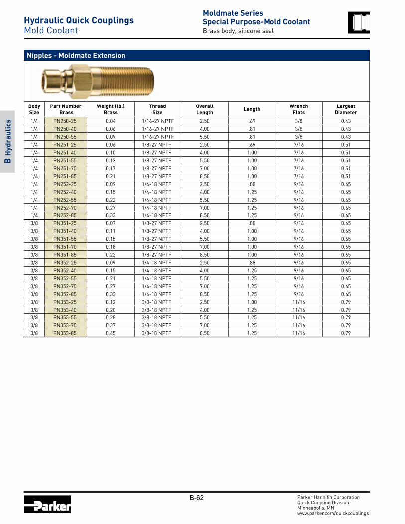
B-62 Parker Hannifin CorporationQuick Coupling DivisionMinneapolis, MN www.parker.com/quickcouplings
B H
ydra
ulic
s
Nipples - Moldmate Extension
Body Size
Part Number Brass
Weight (lb.)Brass
Thread Size
OverallLength Length Wrench
FlatsLargest
Diameter
1/4 PN250-25 0.04 1/16-27 NPTF 2.50 .69 3/8 0.431/4 PN250-40 0.06 1/16-27 NPTF 4.00 .81 3/8 0.431/4 PN250-55 0.09 1/16-27 NPTF 5.50 .81 3/8 0.431/4 PN251-25 0.06 1/8-27 NPTF 2.50 .69 7/16 0.511/4 PN251-40 0.10 1/8-27 NPTF 4.00 1.00 7/16 0.511/4 PN251-55 0.13 1/8-27 NPTF 5.50 1.00 7/16 0.511/4 PN251-70 0.17 1/8-27 NPTF 7.00 1.00 7/16 0.511/4 PN251-85 0.21 1/8-27 NPTF 8.50 1.00 7/16 0.511/4 PN252-25 0.09 1/4-18 NPTF 2.50 .88 9/16 0.651/4 PN252-40 0.15 1/4-18 NPTF 4.00 1.25 9/16 0.651/4 PN252-55 0.22 1/4-18 NPTF 5.50 1.25 9/16 0.651/4 PN252-70 0.27 1/4-18 NPTF 7.00 1.25 9/16 0.651/4 PN252-85 0.33 1/4-18 NPTF 8.50 1.25 9/16 0.653/8 PN351-25 0.07 1/8-27 NPTF 2.50 .88 9/16 0.653/8 PN351-40 0.11 1/8-27 NPTF 4.00 1.00 9/16 0.653/8 PN351-55 0.15 1/8-27 NPTF 5.50 1.00 9/16 0.653/8 PN351-70 0.18 1/8-27 NPTF 7.00 1.00 9/16 0.653/8 PN351-85 0.22 1/8-27 NPTF 8.50 1.00 9/16 0.653/8 PN352-25 0.09 1/4-18 NPTF 2.50 .88 9/16 0.653/8 PN352-40 0.15 1/4-18 NPTF 4.00 1.25 9/16 0.653/8 PN352-55 0.21 1/4-18 NPTF 5.50 1.25 9/16 0.653/8 PN352-70 0.27 1/4-18 NPTF 7.00 1.25 9/16 0.653/8 PN352-85 0.33 1/4-18 NPTF 8.50 1.25 9/16 0.653/8 PN353-25 0.12 3/8-18 NPTF 2.50 1.00 11/16 0.793/8 PN353-40 0.20 3/8-18 NPTF 4.00 1.25 11/16 0.793/8 PN353-55 0.28 3/8-18 NPTF 5.50 1.25 11/16 0.793/8 PN353-70 0.37 3/8-18 NPTF 7.00 1.25 11/16 0.793/8 PN353-85 0.45 3/8-18 NPTF 8.50 1.25 11/16 0.79
Moldmate SeriesSpecial Purpose-Mold CoolantBrass body, silicone seal
Hydraulic Quick Couplings Mold Coolant

B-63 Parker Hannifin CorporationQuick Coupling DivisionMinneapolis, MN www.parker.com/quickcouplings
B H
ydra
ulic
s
Performance DM Series (1/8")Test Fluid: Water
0
2
4
6
8
10
12
0 0.2 0.4 0.6 0.8 1 1.2
Flow in USGP M
Pressure Drop in PSID
1/8"
How To Order
DM - 12 1 - 4
Port Size (1/16 of a inch)
1= Valved Coupler2= Valved Nipple
DM Series
1/8" Body Size
FP
FP= Female NPTMP= Male MPT
DM SeriesSpecial Purpose-MiniatureDouble shut-off, push to connect
Hydraulic Quick Couplings Miniature
DM Series are special purpose miniature couplings that offer double shut-off and push to connect operation in a small envelope. The 1/8 inch brass couplings are nickel plated with standard fluorocarbon seals.
Features:
• Rated pressure is 250 psi
• Double shut-off valving
• Fluorocarbon seals
• Standard end configurations are female and male pipe thread
Applications:
• Dental equipment
• Lubrication lines
• Fluid transfer
• Coolant lines
Specifications Body Size (in.) 1/8
Rated Pressure (psi) 250
Locking Device (balls) 5
Rated Flow (gpm) 0.8
Temperature Range -15°F to +400°F

B-64 Parker Hannifin CorporationQuick Coupling DivisionMinneapolis, MN www.parker.com/quickcouplings
B H
ydra
ulic
s
Couplers - Female Pipe Thread
Body Size Part Number Weight (lb.) Thread Size Overall
LengthLargest
DiameterWrench
Flats
1/8 DM-121-2FP 0.06 1/8-27 NPTF 1.42 0.63 0.551/8 DM-121-4FP 0.10 1/4-18 NPTF 1.81 0.78 0.67
* This dimension represents the portion that is exposed when a nipple is inserted into a Parker DM Series coupler.
* This dimension represents the portion that is exposed when a nipple is inserted into a Parker DM Series coupler.
DM SeriesSpecial Purpose-MiniatureDouble shut-off, push to connect
Hydraulic Quick Couplings Miniature
Couplers - Male Pipe Thread
Body Size Part Number Weight (lb.) Thread Size Overall
LengthLargest
DiameterWrench
Flats
1/8 DM-121-2MP 0.06 1/8-27 NPTF 1.50 0.63 0.551/8 DM-121-4MP 0.07 1/4-18 NPTF 1.61 0.63 0.55
Nipples - Female Pipe Thread
Body Size Part Number Weight (lb.) Thread Size Overall
LengthExposedLength*
LargestDiameter
WrenchFlats
1/8 DM-122-2FP 0.05 1/8-27 NPTF 1.56 1.03 0.63 0.551/8 DM-122-4FP 0.09 1/4-18 NPTF 1.97 1.44 0.78 0.67
Nipples - Male Pipe Thread
Body Size Part Number Weight (lb.) Thread Size Overall
LengthExposedLength*
LargestDiameter
WrenchFlats
1/8 DM-122-2MP 0.05 1/8-27 NPTF 1.65 1.12 0.63 0.551/8 DM-122-4MP 0.06 1/4-18 NPTF 1.77 1.24 0.63 0.55

B-65 Parker Hannifin CorporationQuick Coupling DivisionMinneapolis, MN www.parker.com/quickcouplings
B H
ydra
ulic
s
When ordering Parker coupler bodies and nipples, please state the part number of each type of coupler body and each type of nipple desired. List coupler bodies and nipples as separate items rather than in combinations. Be sure to double check thread or hose sizes of items required.
Many of Parker’s coupling products are available with unique non-standard options well suited to very specific applications. Examples of unusual end use applications might include: high temperatures (above 250° F), extremely caustic/corrosive solutions passing through the coupling, external/environmental corrosion situations, or other high wear and tear situations such as dragging the product along the ground. Please see the Fluid Compatibility Chart at the end of the catalog for a guide in selecting material for various media. It is always recommended that the Quick Coupling Division be contacted with any questions concerning specific product application needs.
Typically, a prefix or suffix is added to the base part number to specify a non-standard O-ring seal, or special option such as a sleeve lock. The Optional Seals Suffix chart illustrates the designations.
N/A = Not Available
STD = Standard (No Suffix Needed)
* To select proper seal materials, see Fluid Compatibility Chart in Ap pen di ces section, or contact your Parker Quick Coupling Distributor.
** Fluorocarbon seal available for use only with oil based media, not water glycol.
*** Contact QCD for Perfluoroelastomer seal options.
Optional Features
• Prefix “HD” for Heavy Duty Nipple• Suffix “SL” for Coupler Sleeve-Lok• Suffix “P” for Poppet Valve• Suffix “BP” for Push-Lok Hose Barb• Suffix “VA” for Valve Actuator
Optional Seals Suffix*
No suffix is required when ordering products with the standard Nitrile seals. When specifying an optional seal, refer to the following chart to determine the appropriate suffix.
Coupling Series
EthylenePropylene
Fluoro-carbon Neoprene Perfluoro-
elastomer60 Series W Y Z ***6600 Series W Y Z ***SM Series E5 E4 E12 ***HP Series E5 E4 E12 ***4000 Series W Y Z N/A4200 Series W Y Z N/ANS Series E5 E4 N/A ***FF SeriesStd. is E49
E5 E4 N/A ***
FH Series E5 E4 N/A ***FS Series E5 STD E12 ***6100 Series W Y Z N/A5000 Series W Y Z N/A8200 Series W Y Z N/A9200 Series W Y Z N/A3000 Series Available with Polyurethane only (no suffix needed)TC Series Available with Fluorocarbon only (no suffix needed)1141 Series Available with Polyurethane only (no suffix needed)ST Series W Y ZWater Service Available with Nitrile onlyHO Series E5 E4 E12 N/AMoldmate SeriesStd. is Silicone
N/A Y** N/A N/A
Ordering InformationHydraulic Quick Couplings
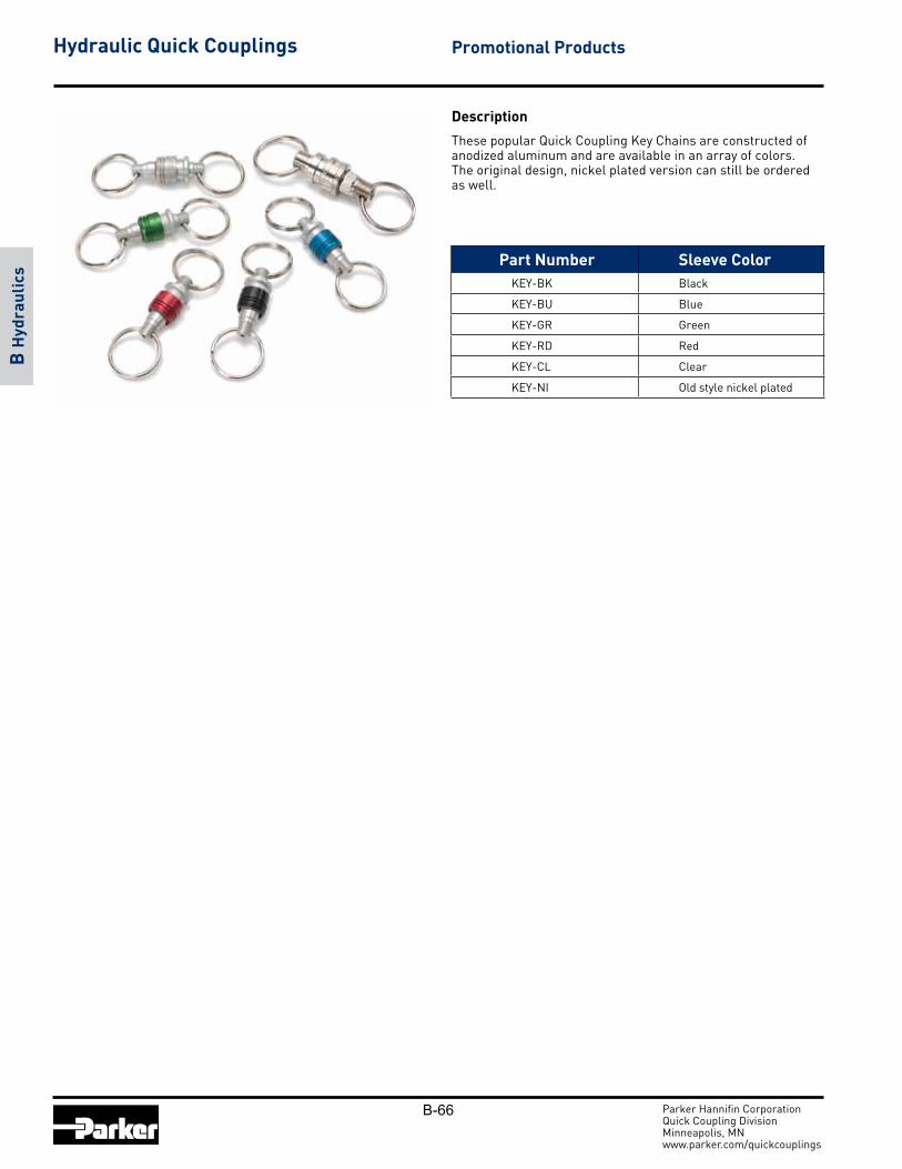
B-66 Parker Hannifin CorporationQuick Coupling DivisionMinneapolis, MN www.parker.com/quickcouplings
B H
ydra
ulic
s
Description
These popular Quick Coupling Key Chains are constructed of anodized aluminum and are available in an array of colors. The original design, nickel plated version can still be ordered as well.
Promotional ProductsHydraulic Quick Couplings
Part Number Sleeve ColorKEY-BK Black
KEY-BU Blue
KEY-GR Green
KEY-RD Red
KEY-CL Clear
KEY-NI Old style nickel plated