Embed Size (px)
Citation preview
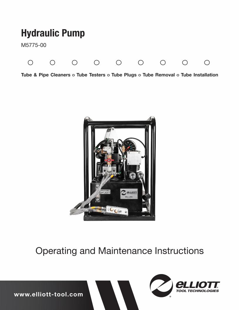
www.elliott-tool.com
Tube & Pipe Cleaners Tube Testers Tube Plugs Tube Removal Tube Installation
Hydraulic PumpM5775-00
Operating and Maintenance Instructions

TABLE OF CONTENTS
Introduction .......................................................................................................... 4
Safety Guidelines ................................................................................................. 5
Parts List & Diagrams ........................................................................................... 6
Warranty ............................................................................................................. 22
4 Hydraulic Pumps
INTRODUCTIONThank you for purchasing this Elliott product. More than 100 years of experience have been employed in the design and manufacture of this control, representing the highest standard of quality, value and durability. Elliott tools have proven themselves in thousands of hours of trouble-free field operation.
If this is your first Elliott purchase, welcome to our company; our products are our ambassadors. If this is a repeat purchase, you can rest assured that the same value you have received in the past will continue with all of your purchases, now and in the future.
If you have any questions regarding this product, manual or operating instructions, please call Elliott at +1 800 332 0447 toll free (USA only) or +1 937 253 6133, or fax us at +1 937 253 9189 for immediate service.

Hydraulic Pumps 5
SAFETY GUIDELINESRead and save all instructions. Before use, be sure everyone using this machine reads and understands this manual, as well as any labels packaged with or attached to the machine.
• Know Your Elliott Tool. Read this manual carefully to learn your tool’s application and limitations as well as the potential hazards specific to this tool.
• Avoid Dangerous Environments. Do not use power tools in damp or wet locations
• Keep Work Area Clean and Well Lit. Cluttered, dark work areas invite accidents.
• Use Safety Equipment. Everyone in the work area should wear safety goggles or glasses with side shields complying with current safety standards.
• Use The Right Tools. Do not force a tool or attachment to do a job or operate at a speed it was not designed for.
• Use Proper Accessories. Use Elliott accessories only. Be sure accessories are properly installed and maintained.
• Check for Damaged Parts. Inspect guards and other parts before use. Check for misalignment, binding of moving parts, improper mounting, broken parts or any other conditions that may affect operation. If abnormal noise or vibration occurs, turn the tool off immediately and have the problem corrected before further use. Do not use a damaged tool. Tag damaged tools “Do Not Use” until repaired. A damaged part should be properly repaired or replaced by an Elliott service facility.
• Unplug Tool. Unplug tool when it is not in use, before changing accessories or performing recommended maintenance.
• Maintain Labels and Nameplates. These carry important information and will assist you in ordering spare and replacement parts. If unreadable or missing, contact an Elliott service facility for a replacement.
6 Hydraulic Pumps
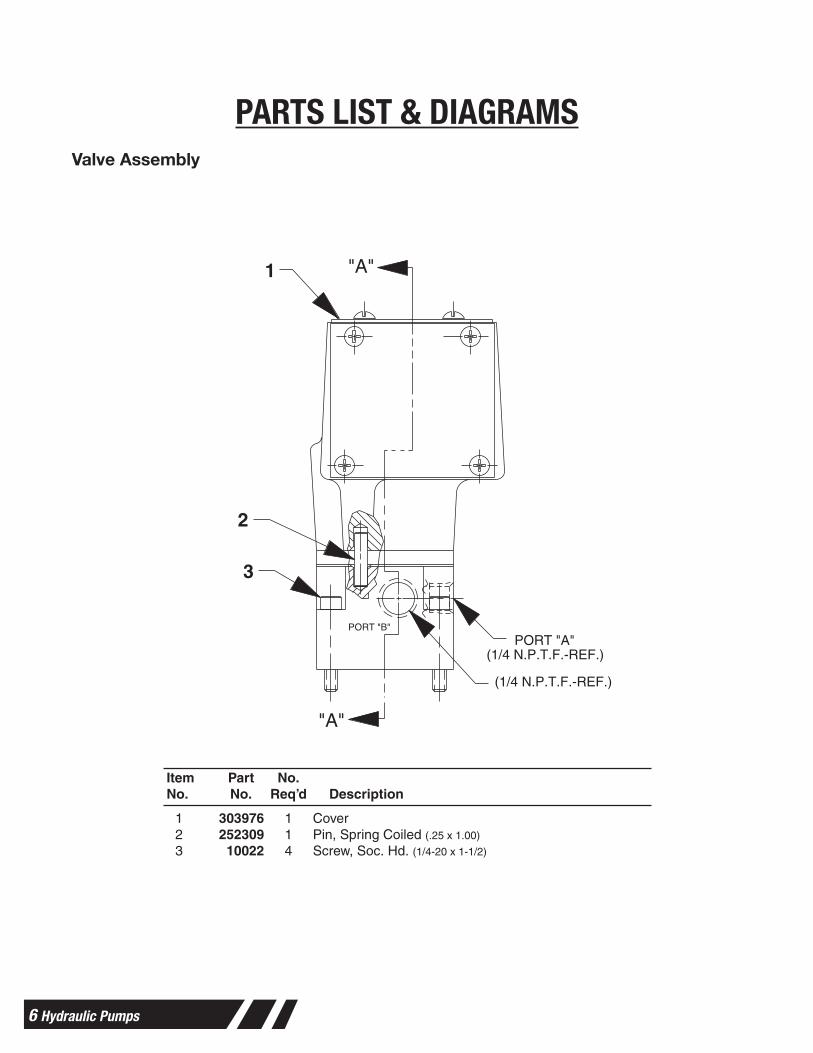
PARTS LIST & DIAGRAMS Valve Assembly
VALVE ASSEMBLY
Form No. 108100Parts List for:
66209
"A"
"A"
(1/4 N.P.T.F.-REF.)
(1/4 N.P.T.F.-REF.)PORT "A"
PORT "B"
1
2
3
Sheet No. 1 of 2
Rev. Date: 20 Oct. 1999
1 303976 1 Cover2 252309 1 Pin, Spring Coiled (.25 x 1.00)
3 10022 4 Screw, Soc. Hd. (1/4-20 x 1-1/2)
Item Part No.No. No. Req’d Description
© SPX Corporation
Tech. Services: (800) 477-8326Fax: (800) 765-8326
Order Entry: (800) 541-1418Fax: (800) 288-7031
SPX Corporation5885 11th StreetRockford, IL 61109-3699 USA
Internet Address: http://www.powerteam.com
®
Hydraulic Pumps 7
PARTS LIST & DIAGRAMSValve AssemblyParts List, Form No. 108100, Back sheet 1 of 2
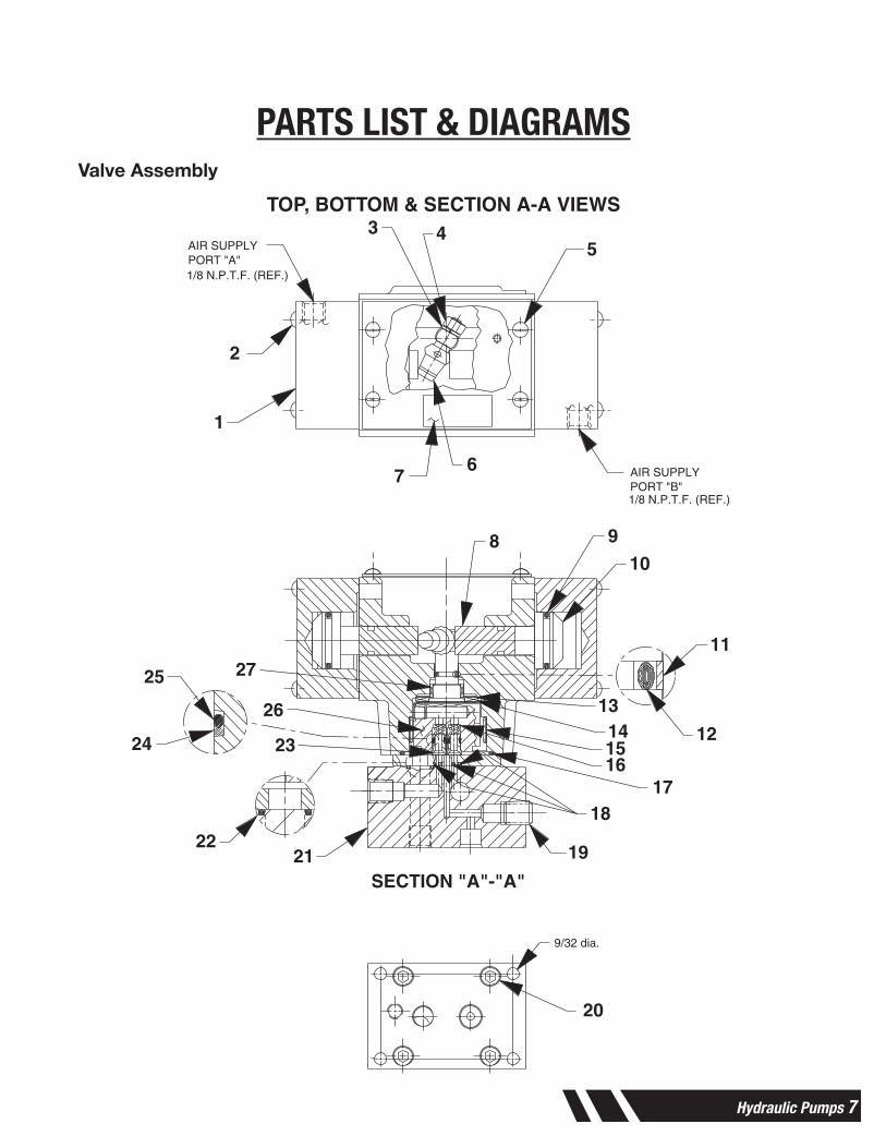
TOP, BOTTOM & SECTION A-A VIEWS
1/8 N.P.T.F. (REF.)
AIR SUPPLYPORT "A"
1/8 N.P.T.F. (REF.)
AIR SUPPLYPORT "B"
SECTION "A"-"A"
MOUNTING HOLE DIMENSIONS
9/32 dia.
1
2
3 45
67
8 9
10
11
12
13141516
1718
19
20
2122
24
25
23
26
27
8 Hydraulic Pumps
PARTS LIST & DIAGRAMS
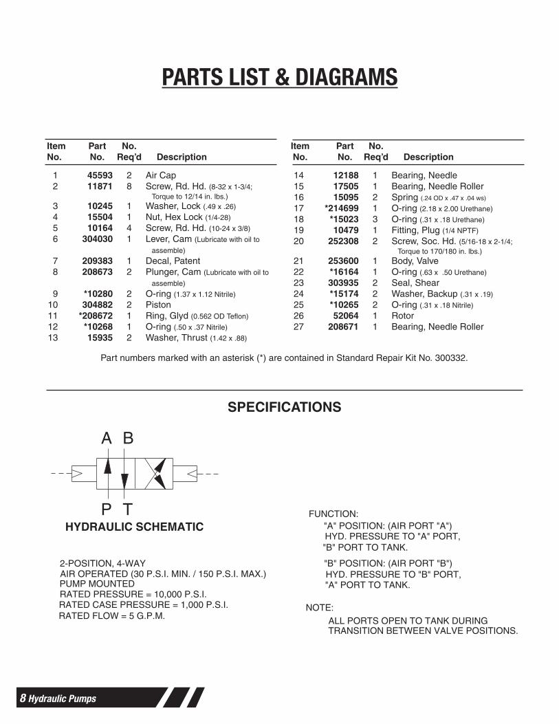
1 45593 2 Air Cap2 11871 8 Screw, Rd. Hd. (8-32 x 1-3/4;
Torque to 12/14 in. lbs.)3 10245 1 Washer, Lock (.49 x .26)
4 15504 1 Nut, Hex Lock (1/4-28)
5 10164 4 Screw, Rd. Hd. (10-24 x 3/8)
6 304030 1 Lever, Cam (Lubricate with oil to
assemble)
7 209383 1 Decal, Patent8 208673 2 Plunger, Cam (Lubricate with oil to
assemble)
9 *10280 2 O-ring (1.37 x 1.12 Nitrile)
10 304882 2 Piston11 *208672 1 Ring, Glyd (0.562 OD Teflon)
12 *10268 1 O-ring (.50 x .37 Nitrile)
13 15935 2 Washer, Thrust (1.42 x .88)
14 12188 1 Bearing, Needle15 17505 1 Bearing, Needle Roller16 15095 2 Spring (.24 OD x .47 x .04 ws)
17 *214699 1 O-ring (2.18 x 2.00 Urethane)
18 *15023 3 O-ring (.31 x .18 Urethane)
19 10479 1 Fitting, Plug (1/4 NPTF)
20 252308 2 Screw, Soc. Hd. (5/16-18 x 2-1/4;Torque to 170/180 in. lbs.)
21 253600 1 Body, Valve22 *16164 1 O-ring (.63 x .50 Urethane)
23 303935 2 Seal, Shear24 *15174 2 Washer, Backup (.31 x .19)
25 *10265 2 O-ring (.31 x .18 Nitrile)
26 52064 1 Rotor27 208671 1 Bearing, Needle Roller
Item Part No. Item Part No.No. No. Req’d Description No. No. Req’d Description
Parts List Form No. 108100
Sheet No. 2 of 2
Rev. Date: 20 Oct. 1999
AIR OPERATED (30 P.S.I. MIN. / 150 P.S.I. MAX.)"A" PORT TO TANK. HYD. PRESSURE TO "B" PORT,"B" POSITION: (AIR PORT "B")
"B" PORT TO TANK. HYD. PRESSURE TO "A" PORT,"A" POSITION: (AIR PORT "A")
TRANSITION BETWEEN VALVE POSITIONS.ALL PORTS OPEN TO TANK DURING
NOTE:
FUNCTION:
RATED FLOW = 5 G.P.M.RATED CASE PRESSURE = 1,000 P.S.I.RATED PRESSURE = 10,000 P.S.I.PUMP MOUNTED
2-POSITION, 4-WAY
HYDRAULIC SCHEMATIC
BA
TP
SPECIFICATIONS
Part numbers marked with an asterisk (*) are contained in Standard Repair Kit No. 300332.
Hydraulic Pumps 9
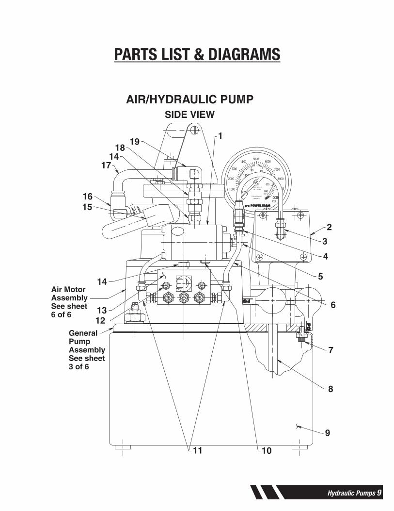
PARTS LIST & DIAGRAMS
MODEL C
AIR/HYDRAULIC PUMPSIDE VIEW
Form No. 108126Parts List for:
PA55-ETT
Sheet No. 1 of 6
Rev. 1 Date: 7 Nov. 2000
NO. 90521000
2000
3 000
4 0005000
6000
7000
8000
PSI
bar690
600
4 003 00
0
USE ONLY
FOR HYDRAULIC
MADE IN U.S.A.
w seilpmoC
1
2
3
4
5
6
7
8
9
1011
1213
14
1516
17
1819
14
GeneralPumpAssemblySee sheet3 of 6
Air MotorAssemblySee sheet6 of 6
Tech. Services: (800) 477-8326Fax: (800) 765-8326
Order Entry: (800) 541-1418Fax: (800) 288-7031
SPX Corporation5885 11th StreetRockford, IL 61109-3699 USA
Internet Address: http://www.powerteam.com
®
© SPX Corporation
10 Hydraulic Pumps
PARTS LIST & DIAGRAMSParts List, Form No. 108126, Back sheet 1 of 6
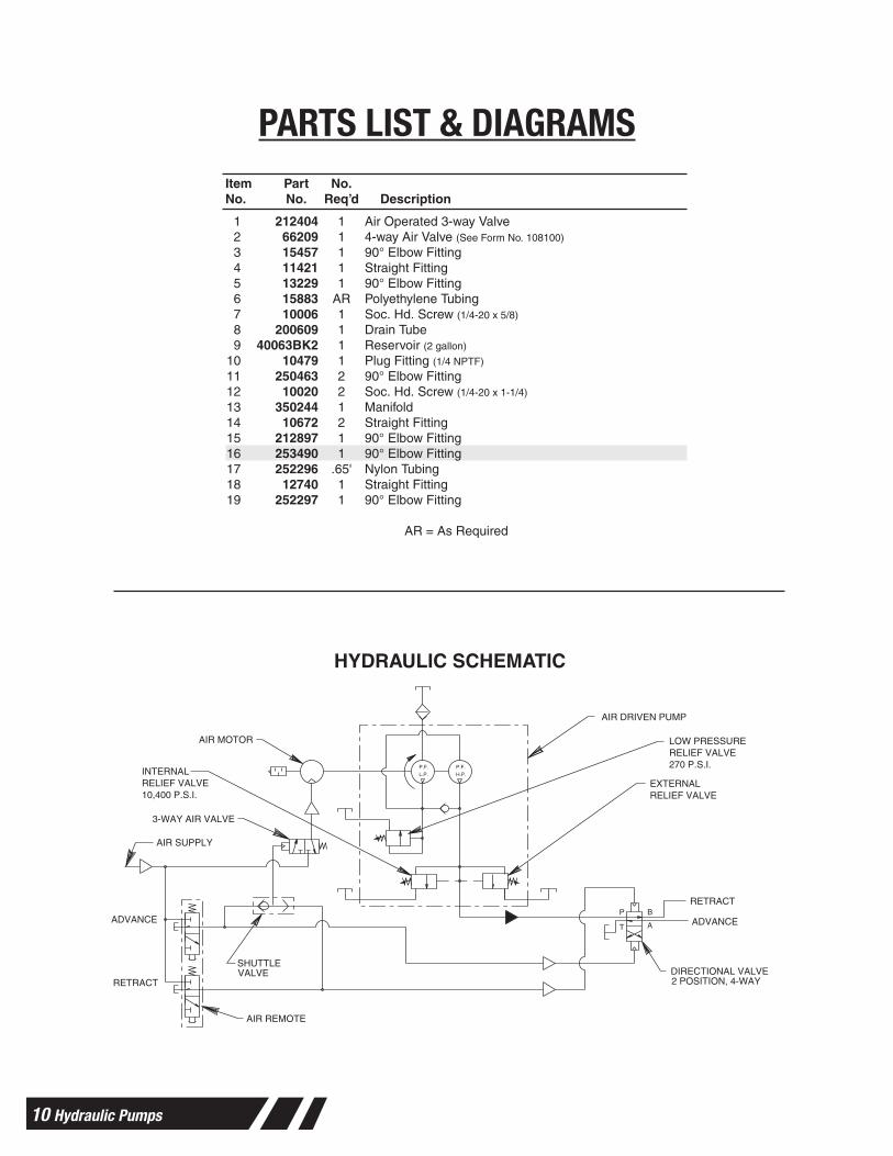
HYDRAULIC SCHEMATIC
1 212404 1 Air Operated 3-way Valve2 66209 1 4-way Air Valve (See Form No. 108100)
3 15457 1 90° Elbow Fitting4 11421 1 Straight Fitting5 13229 1 90° Elbow Fitting6 15883 AR Polyethylene Tubing7 10006 1 Soc. Hd. Screw (1/4-20 x 5/8)
8 200609 1 Drain Tube9 40063BK2 1 Reservoir (2 gallon)
10 10479 1 Plug Fitting (1/4 NPTF)
11 250463 2 90° Elbow Fitting12 10020 2 Soc. Hd. Screw (1/4-20 x 1-1/4)
13 350244 1 Manifold14 10672 2 Straight Fitting15 212897 1 90° Elbow Fitting16 253490 1 90° Elbow Fitting17 252296 .65' Nylon Tubing18 12740 1 Straight Fitting19 252297 1 90° Elbow Fitting
AR = As Required
Item Part No.No. No. Req’d Description
VALVESHUTTLE
10,400 P.S.I.RELIEF VALVEINTERNAL
RELIEF VALVEEXTERNAL
270 P.S.I.RELIEF VALVELOW PRESSURE
RETRACT
ADVANCEAT
BP
3-WAY AIR VALVE
2 POSITION, 4-WAYDIRECTIONAL VALVE
AIR SUPPLY
AIR DRIVEN PUMP
AIR MOTOR
AIR REMOTE
RETRACT
ADVANCE
H.P.P.F.
L.P.P.F.
Note: Shaded areas reflect last revision(s) made to this form.
Hydraulic Pumps 11
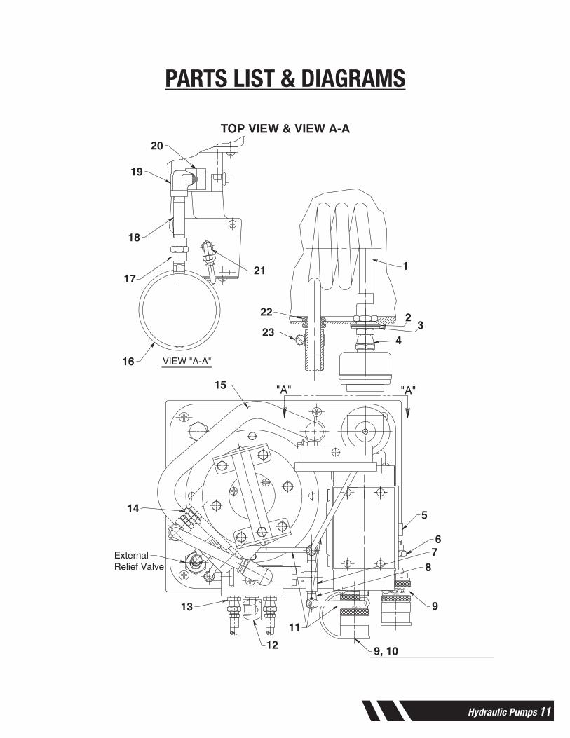
PARTS LIST & DIAGRAMSParts List Form No. 108126
TOP VIEW & VIEW A-A
Sheet No. 2 of 6
Rev. 1 Date: 7 Nov. 2000
"A""A"
VIEW "A-A"
9796
9796
1
23
4
5
67
8
9
9, 10
11
12
13
14
15
16
17
18
19
20
21
22
23
ExternalRelief Valve
12 Hydraulic Pumps
PARTS LIST & DIAGRAMSParts List, Form No. 108126, Back sheet 2 of 6
1 46626 1 Heat Exchanger Coil2 252041 1 Seal Washer (1.50 x 1.05)
3 18286 1 Special Washer (1.38 x .89)
4 252355 1 Straight Fitting (Torque to 80/100 in. lbs.)
5 250381 1 90° Elbow Fitting6 13831 1 Straight Fitting7 212405 1 Check Valve (1000 PSI)
8 15378 2 Tee Fitting9 9796 2 Cylinder Half Coupler w/ Dust Cap
10 9689 1 Reducer Connector11 15883 AR Polyethylene Tubing12 10621 1 90° Elbow Fitting13 208218 6 Straight Fitting14 250260 1 Straight Fitting15 212890 1.5' Pressure Hose16 9052 1 Gauge (10,000 PSI; 4" dia.)
17 12740 1 Straight Fitting18 250026 1 Straight Fitting19 10617 1 90° Elbow Fitting20 9678 1 45° Fitting21 15457 1 90° Elbow Fitting22 212896 1 Rubber Grommet23 12367 2 Hose Clamp
AR = As Required
Item Part No.No. No. Req’d Description
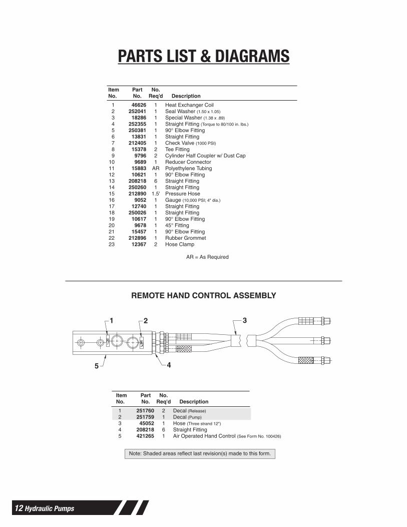
REMOTE HAND CONTROL ASSEMBLY
1 2 3
45
Item Part No.No. No. Req'd Description
1 251760 2 Decal (Release)
2 251759 1 Decal (Pump)
3 45052 1 Hose (Three strand 12")
4 208218 6 Straight Fitting5 421265 1 Air Operated Hand Control (See Form No. 100426)
Note: Shaded areas reflect last revision(s) made to this form.
Hydraulic Pumps 13
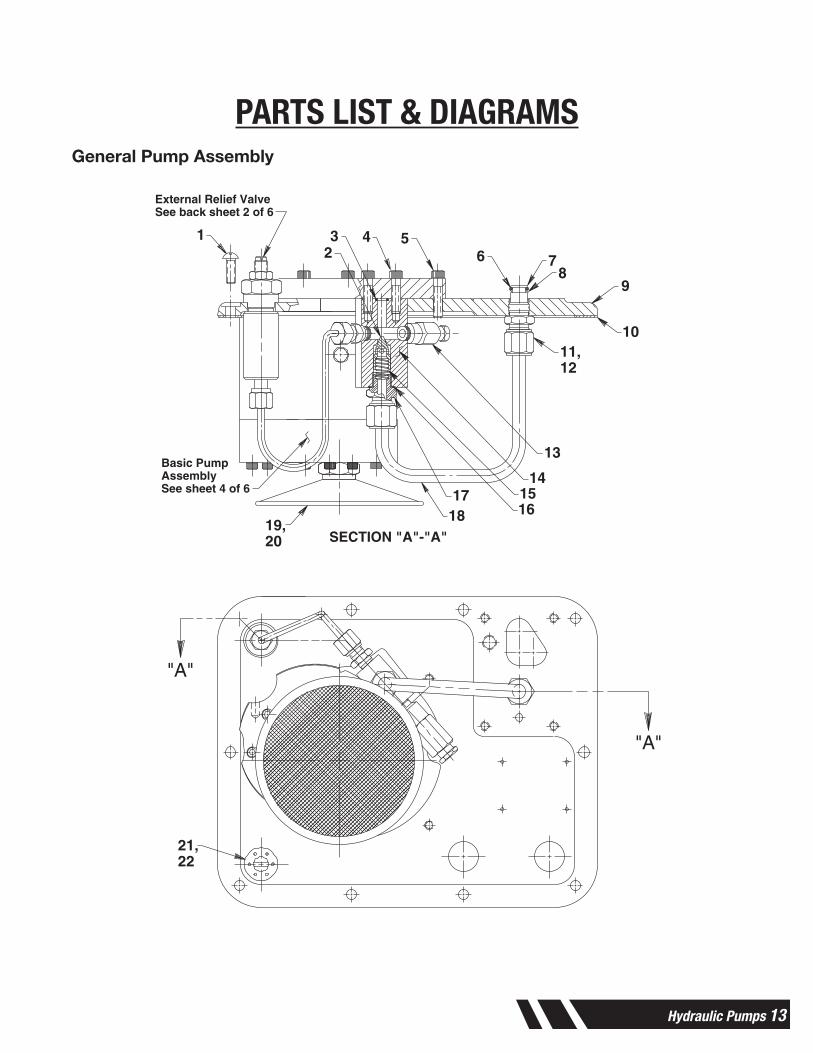
PARTS LIST & DIAGRAMSGeneral Pump Assembly
Parts List Form No. 108126
GENERAL PUMP ASSEMBLY
Sheet No. 3 of 6
Rev. 1 Date: 7 Nov. 2000
SECTION "A"-"A"
"A"
"A"
123 4 5
6 78
9
1011,12
13
141516
1718
19,20
21,22
External Relief ValveSee back sheet 2 of 6
Basic PumpAssemblySee sheet 4 of 6
14 Hydraulic Pumps
PARTS LIST & DIAGRAMSParts List, Form No. 108126, Back sheet 3 of 6
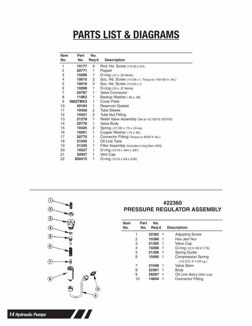
1 10177 9 Rnd. Hd. Screw (1/4-20 x 3/4)
2 20771 1 Poppet3 10266 1 O-ring (.37 x .25 Nitrile)
4 10015 2 Soc. Hd. Screw (1/4-28 x 1; Torque to 140/160 in. lbs.)
5 10016 3 Soc. Hd. Screw (1/4-20 x 1)
6 10268 1 O-ring (.50 x .37 Nitrile)
7 20787 1 Valve Connector8 11863 1 Backup Washer (.50 x .38)
9 46627BK2 1 Cover Plate10 40164 1 Reservoir Gasket11 10430 2 Tube Sleeve12 10431 2 Tube Nut Fitting13 21278 1 Relief Valve Assembly (Set at 10,100/10,700 PSI)
14 20776 1 Valve Body15 10425 2 Spring (.37 OD x .75 x .03 ws)
16 10261 1 Copper Washer (.75 x .60)
17 20770 1 Connector Fitting (Torque to 40/50 ft. lbs.)
18 21045 1 Oil Line Tube19 21345 1 Filter Assembly (Includes o-ring [Item #20])
20 10527 1 O-ring (13/16 x .644 x .087)
21 20937 1 Vent Cap22 200415 1 O-ring (13/16 x 5/8 x 3/32)
Item Part No.No. No. Req’d Description
#22360PRESSURE REGULATOR ASSEMBLY
Item Part No.No. No. Req'd Description
1 22362 1 Adjusting Screw2 10386 1 Hex Jam Nut3 21305 1 Valve Cap4 10268 1 O-ring (1/2 X 3/8 X 1/16)
5 21306 1 Spring Guide6 10495 1 Compression Spring
(1/2 O.D. X 1-5/8 Lg.)
7 21046 1 Valve Stem8 22361 1 Body9 29267 1 Oil Line Ass'y (With nuts)
10 14844 1 Connector Fitting
Hydraulic Pumps 15
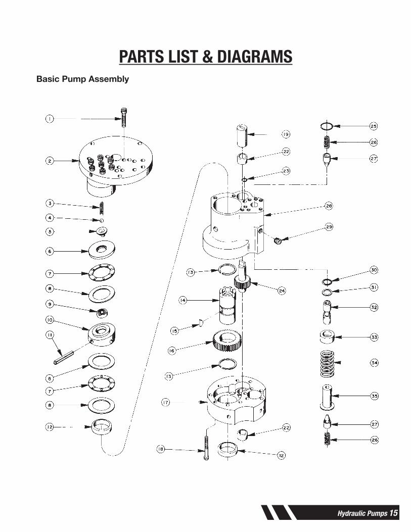
PARTS LIST & DIAGRAMSBasic Pump Assembly
Parts List Form No. 108126
BASIC PUMP ASSEMBLY
Sheet No. 4 of 6
Rev. 1 Date: 7 Nov. 2000
16 Hydraulic Pumps
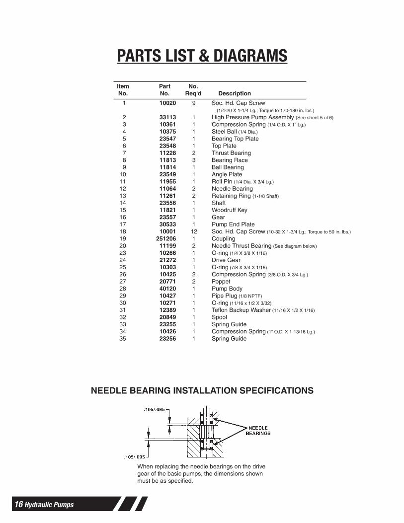
PARTS LIST & DIAGRAMSParts List, Form No. 108126, Back sheet 4 of 6
NEEDLE BEARING INSTALLATION SPECIFICATIONS
1 10020 9 Soc. Hd. Cap Screw (1/4-20 X 1-1/4 Lg.; Torque to 170-180 in. lbs.)
2 33113 1 High Pressure Pump Assembly (See sheet 5 of 6)
3 10361 1 Compression Spring (1/4 O.D. X 1” Lg.)
4 10375 1 Steel Ball (1/4 Dia.)
5 23547 1 Bearing Top Plate6 23548 1 Top Plate7 11228 2 Thrust Bearing8 11813 3 Bearing Race9 11814 1 Ball Bearing
10 23549 1 Angle Plate11 11955 1 Roll Pin (1/4 Dia. X 3/4 Lg.)
12 11064 2 Needle Bearing13 11261 2 Retaining Ring (1-1/8 Shaft)
14 23556 1 Shaft15 11821 1 Woodruff Key16 23557 1 Gear17 30533 1 Pump End Plate18 10001 12 Soc. Hd. Cap Screw (10-32 X 1-3/4 Lg.; Torque to 50 in. lbs.)
19 251206 1 Coupling20 11199 2 Needle Thrust Bearing (See diagram below)
23 10266 1 O-ring (1/4 X 3/8 X 1/16)
24 21272 1 Drive Gear25 10303 1 O-ring (7/8 X 3/4 X 1/16)
26 10425 2 Compression Spring (3/8 O.D. X 3/4 Lg.)
27 20771 2 Poppet28 40120 1 Pump Body29 10427 1 Pipe Plug (1/8 NPTF)
30 10271 1 O-ring (11/16 x 1/2 X 3/32)
31 12389 1 Teflon Backup Washer (11/16 X 1/2 X 1/16)
32 20849 1 Spool33 23255 1 Spring Guide34 10426 1 Compression Spring (1” O.D. X 1-13/16 Lg.)
35 23256 1 Spring Guide
When replacing the needle bearings on the drivegear of the basic pumps, the dimensions shownmust be as specified.
Item Part No.No. No. Req'd Description
Hydraulic Pumps 17
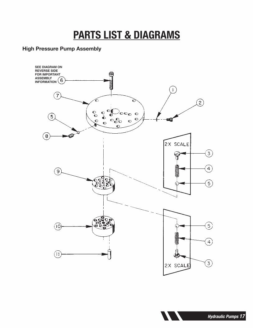
PARTS LIST & DIAGRAMSHigh Pressure Pump Assembly
Parts List Form No. 108126
HIGH PRESSURE PUMP ASSEMBLY
Sheet No. 5 of 6
Rev. 1 Date: 7 Nov. 2000
SEE DIAGRAM ONREVERSE SIDEFOR IMPORTANTASSEMBLYINFORMATION
18 Hydraulic Pumps
PARTS LIST & DIAGRAMSParts List, Form No. 108126, Back sheet 5 of 6
Item Part No.No. No. Req'd Description
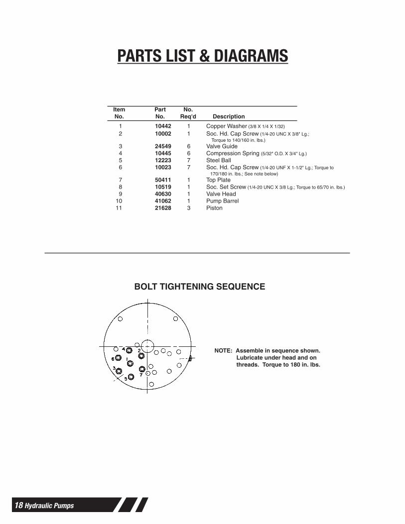
1 10442 1 Copper Washer (3/8 X 1/4 X 1/32)
2 10002 1 Soc. Hd. Cap Screw (1/4-20 UNC X 3/8" Lg.;Torque to 140/160 in. lbs.)
3 24549 6 Valve Guide4 10445 6 Compression Spring (5/32" O.D. X 3/4" Lg.)
5 12223 7 Steel Ball6 10023 7 Soc. Hd. Cap Screw (1/4-20 UNF X 1-1/2" Lg.; Torque to
170/180 in. lbs.; See note below)7 50411 1 Top Plate8 10519 1 Soc. Set Screw (1/4-20 UNC X 3/8 Lg.; Torque to 65/70 in. lbs.)
9 40630 1 Valve Head10 41062 1 Pump Barrel11 21628 3 Piston
BOLT TIGHTENING SEQUENCE
NOTE: Assemble in sequence shown.Lubricate under head and onthreads. Torque to 180 in. lbs.
Hydraulic Pumps 19
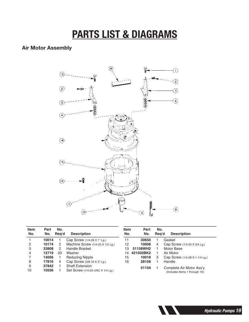
PARTS LIST & DIAGRAMSAir Motor Assembly
Parts List Form No. 108126
AIR MOTOR ASSEMBLY
Sheet No. 6 of 6
Rev. 1 Date: 7 Nov. 2000
Item Part No. Item Part No.No. No. Req'd Description No. No. Req'd Description
1 10014 1 Cap Screw (1/4-28 X 1” Lg.)
2 10174 2 Machine Screw (1/4-20 X 1/2 Lg.)
3 33808 2 Handle Bracket4 12719 20 Washer7 14056 1 Reducing Nipple8 17816 4 Cap Screw (3/8-16 X 3” Lg.)
9 37842 1 Shaft Extension10 10556 1 Set Screw (1/4-20 UNC X 1/4 Lg.)
11 30650 1 Gasket12 10008 4 Cap Screw (1/4-20 X 3/4 Lg.)
13 51158WH2 1 Motor Base14 421502BK2 1 Air Motor15 10018 3 Cap Screw (1/4-28 X 1-1/4 Lg.)
16 28158 1 Handle
51159 1 Complete Air Motor Ass’y (Includes Items 1 through 16)
20 Hydraulic Pumps
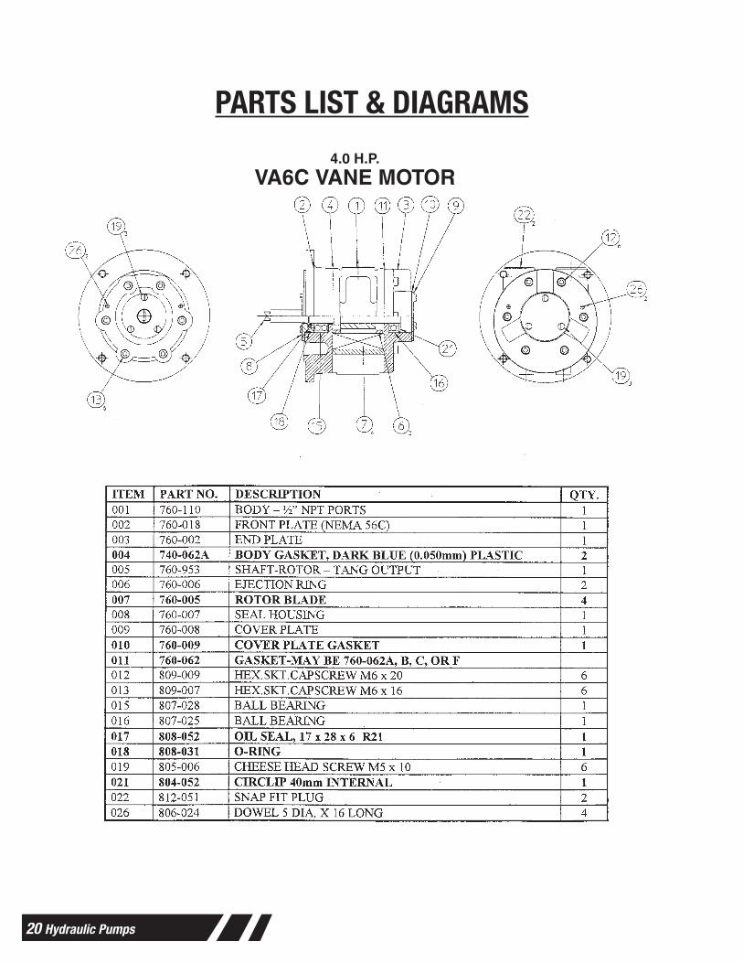
PARTS LIST & DIAGRAMS4.0 H.P.
VA6C VANE MOTOR
Form No. 108171Parts List for:
66484760-954
Sheet No. 1 of 1
Rev. Date: 2 Mar. 2001© SPX Corporation
Tech. Services: (800) 477-8326Fax: (800) 765-8326
Order Entry: (800) 541-1418Fax: (800) 288-7031
SPX Corporation5885 11th StreetRockford, IL 61109-3699 USA
Internet Address: http://www.powerteam.com
®
Hydraulic Pumps 21
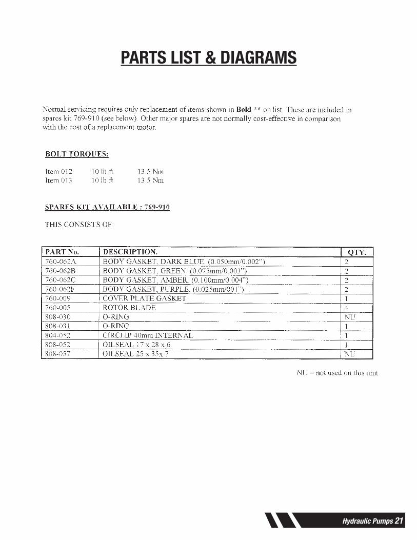
PARTS LIST & DIAGRAMSParts List, Form No. 108171, Back sheet 1 of 1
22 Hydraulic Pumps
WARRANTYShould any part, of Seller’s own manufacture, prove to have been defective in material or workmanship when shipped (as determined by Seller), Seller warrants that it will, at its sole option, repair or replace said part f.o.b., point of manufacture, provided that Buyer notifies, in writing, of such defect within twelve (12) months from date of shipment from the manufacturing plant.
On request of Seller, the part claimed to be defective will be returned, transportation, insurance, taxes and duties prepaid, to the factory where made, for inspection. Any item, which has been purchased by Seller, is warranted only to the extent of the original manufacturer’s warranty to Seller. Seller shall not be liable for any damages or delays caused by defective material or workmanship.
No allowance will be made for repairs or alterations made by others without Seller’s written consent or approval. If repairs or alterations are attempted without Seller’s consent, Seller’s warranty is void.
THE WARRANTIES PROVIDED IN THE OBLIGATIONS AND LIABILITIES OF SELLER HEREUNDER, AND THE RIGHTS AND REMEDIES OF BUYER HEREUNDER ARE EXCLUSIVE AND IN SUBSTITUTION FOR, AND BUYER HEREBY WAIVES ALL OTHER WARRANTIES, GUARANTEES, OBLIGATIONS, CLAIMS FOR LIABILITIES, RIGHTS AND REMEDIES, EXPRESS OR IMPLIED, ARISING BY LAW OR OTHERWISE, INCLUDING BUT NOT LIMITED TO THE IMPLIED WARRANTY FOR MERCHANTABILITY AND FITNESS FOR PURPOSE. Seller’s total liability is limited to the lower of the cost of repair or replacement.

Hydraulic Pumps 23

Elliott Tool Technologies, Ltd. 1760 Tuttle Avenue Dayton, Ohio 45403-3428Phone: +1 937 253 6133 • +1 800 332 0447 Fax: +1 937 253 9189www.ell iott-tool.com
Printed in the USA©04/2020 Elliott Tool Technologies, Ltd.TM-97PL-72
Elliott Tool offers a complete line of precision tube tools to meet your needs. Contact us or your local support.
Contact Us
www.elliott-tool.com/support
Locally Supported By: