Embed Size (px)
Citation preview

Hydraulic Power SupplyPowerPack PP73
PowerPack PP4000PowerPack PP20
PowerPack PP13A
PP70/73_PP20_PP13_09_08SERIAL NO. 101 -
ORDER NO. OM1610
Operator and Maintenance Manual

Introduction
-2 Hydraulic PowerPack
INTRODUCTIONThis manual explains the proper operation of your machine. Study and understand these instructions thoroughly before operating or maintaining the machine. Failure to do so could result in personal injury or equipment damage. Consult your HammerHead dealer if you do not understand the instructions in this manual, or need additional information.
The instructions, illustrations, and specifications in this manual are based on the latest information available at time of publication. Your machine may have product improvements and features not yet contained in this manual.
Earth Tool Company LLC reserves the right to make changes at any time without notice or obligation.
Operation instructions are included in the two Operator’s Manuals provided with the machine. The tethered (cabled) manual must remain attached to the machine for ready reference. Store it in the manual storage box when not in use.
Lubrication and maintenance procedures are in the Maintenance Manual provided with the machine. Refer to it for all lubrication and maintenance procedures.
Additional copies of the manuals are available from your dealer. Use the reorder number on the front cover to order additional manuals.
Copyright © 2011 All rights reserved.Earth Tool Company LLC
1300 Capitol DriveOconomowoc, Wisconsin 53066
Hydraulic PowerPack -5
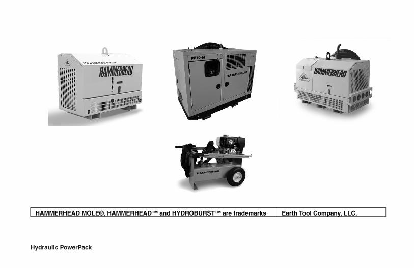
HAMMERHEAD MOLE®, HAMMERHEAD™ and HYDROBURST™ are trademarks Earth Tool Company, LLC.
-6 Hydraulic PowerPack
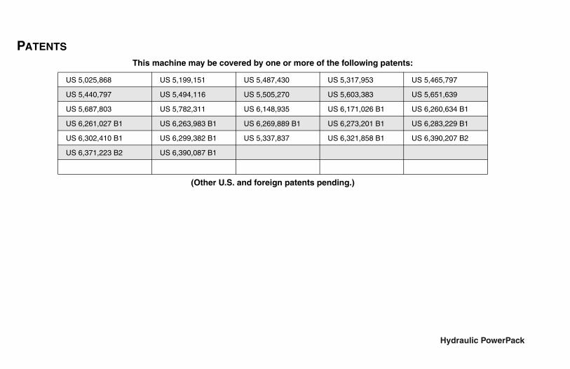
PATENTS
This machine may be covered by one or more of the following patents:
(Other U.S. and foreign patents pending.)
US 5,025,868 US 5,199,151 US 5,487,430 US 5,317,953 US 5,465,797
US 5,440,797 US 5,494,116 US 5,505,270 US 5,603,383 US 5,651,639
US 5,687,803 US 5,782,311 US 6,148,935 US 6,171,026 B1 US 6,260,634 B1
US 6,261,027 B1 US 6,263,983 B1 US 6,269,889 B1 US 6,273,201 B1 US 6,283,229 B1
US 6,302,410 B1 US 6,299,382 B1 US 5,337,837 US 6,321,858 B1 US 6,390,207 B2
US 6,371,223 B2 US 6,390,087 B1

Hydraulic PowerPack -7
HAMMERHEAD EQUIPMENT LIMITED WARRANTYEARTH TOOL COMPANY LLC, hereinafter sometimes referred to as ETC warrants each new industrial product of its own
manufacture to be free from defects in material and workmanship, under normal use and service for one full year after delivery to the owner or 1000 operating hours, whichever occurs first. During the warranty period, the authorized selling HammerHead Dealer shall furnish parts without charge for any HammerHead product that fails because of defects in material and workmanship. Warranty is void unless warranty registration card is returned within ten days from the date of purchase. This warranty and any possible liability of Earth Tool Company LLC here under is in lieu of all other warranties, express, implied, or statutory, including, but not limited to any warranties of merchantability or fitness for a particular purpose.
The parties agree that the Buyer’s SOLE AND EXCLUSIVE REMEDY against ETC, whether in contract or arising out of warranties, representations, or defects shall be for the replacement or repair of defective parts as provided herein. In no event shall ETC’s liability exceed the purchase price of the product. The Buyer agrees that no other remedy (including, but not limited to, incidental or consequential loss) shall be available to him. If, during the warranty period, any product becomes defective by reason of material or workmanship and Buyer immediately notifies ETC of such defect, ETC shall, at its option, supply a replacement part or request the return of the product to its plant in Oconomowoc, Wisconsin. No part shall be returned without prior written authorization from ETC, and this warranty does not obligate ETC to bear any transportation charges in connection with the repair or replacement of defective parts. earth Tool Company LLC will not accept any charges for labor and/or parts incidental to the removal or remounting of parts repaired or replaced under this Warranty.
This Warranty shall not apply to any part or product which shall have been installed or operated in a manner not recommended by ETC nor to any part or product which shall have been neglected, or used in any way which, in ETC’s opinion, adversely affects its performance; nor negligence of proper maintenance or other negligence, fire or other accident; nor with respect to wear items; nor if the unit has been repaired or altered outside of an ETC authorized dealership in a manner of which, in the sole judgment of ETC affects its performance, stability or reliability; nor with respect to batteries which are covered under a separate adjustment warranty; nor to any product in which parts not manufactured or approved by ETC have been used, nor to normal maintenance services or replacement of normal service items. Equipment and accessories not of our manufacture are warranted only to the extent of the original Manufacturer’s Warranty and subject to their allowance to us, if found defective by them. ETC reserves the right to modify, alter, and improve any products or parts without incurring any obligation to replace any product or parts previously sold
with such modified, altered, or improved product or part. No person is authorized to give any other Warranty, or to assume any additional obligation on ETC’s behalf unless made in writing, and signed by an officer of ETC.
EARTH TOOL COMPANY LLC
Oconomowoc, Wisconsin

This page intentionally left blank.

Receiving and Delivery Report
Hydraulic PowerPack i
Receiving and Delivery ReportDEALER PREP
Check or perform the following:
___ Check machine for shortage or damage in transit.
Engine
___ Check engine oil level.
___ Check engine coolant level.
___ Check battery electrolyte level and charge.
___ Check air cleaner condition.
___ Check engine for proper operation.
Hydraulics
___ Check hydraulic fluid level. (HB175,HB125, HB80 and HB100T - check level with cylinders retracted)
___ Check all hydraulic components for leaks or damage.
___ Check all hydraulic connections for foreign objects and dirt.
General
___ Check tension of alternator/fan belt.
___ Check installation and condition of shields.
___ Check machine for proper lubrication.
___ Check tightness of nuts and bolts.
___ Check condition of all decals.
___ Check all phases of operation.

Receiving and Delivery Report
ii Hydraulic PowerPack
DEALER / CUSTOMER INFORMATION
dealer owner
address address
city city
state / province state / province
zip / postal code zip / postal code
country country

Receiving and Delivery Report
Hydraulic PowerPack iii
MACHINE IDENTIFICATION NUMBERS - RECORD
Engine Model Number _____________
Engine Serial Number _____________
Model Number______________
Model Serial Number____________

Receiving and Delivery Report
iv Hydraulic PowerPack
DELIVERY
Check and perform the following with the customer:
Hydraulic PowerPack System
___ Review all sections of the Operator’s Manual.
___ Grease or oil all lubrication points.
Review of Operation
Review and demonstrate with the customer the various aspects of Hydraulic PowerPack operation:
___ overall explanation of how the Hydraulic PowerPack system works
___ preparing the Hydraulic PowerPack system for operation

Table of Contents
HB3038/HB5058 HydroBurst v
TABLE OF CONTENTS
Dealer Prep . . . . . . . . . . . . . . . . . . . . . . . . . . . . . . . . . . . . . . . iEngine. . . . . . . . . . . . . . . . . . . . . . . . . . . . . . . . . . . . . . . . . iHydraulics . . . . . . . . . . . . . . . . . . . . . . . . . . . . . . . . . . . . . . iGeneral . . . . . . . . . . . . . . . . . . . . . . . . . . . . . . . . . . . . . . . . i
Dealer / Customer Information. . . . . . . . . . . . . . . . . . . . . . . . . iiMachine Identification Numbers - Record . . . . . . . . . . . . . . . . iiiDelivery . . . . . . . . . . . . . . . . . . . . . . . . . . . . . . . . . . . . . . . . . iv
HydroBurst Pipe Bursting System . . . . . . . . . . . . . . . . . . ivReview of Operation . . . . . . . . . . . . . . . . . . . . . . . . . . . . . iv
Safety Messages . . . . . . . . . . . . . . . . . . . . . . . . . . . . . . . . . 10-1
Safety Decals . . . . . . . . . . . . . . . . . . . . . . . . . . . . . . . . . . . . 11-1Safety Decal Maintenance. . . . . . . . . . . . . . . . . . . . . . . . . 11-1
Machine Controls . . . . . . . . . . . . . . . . . . . . . . . . . . . . . . . . 20-1Machine Controls . . . . . . . . . . . . . . . . . . . . . . . . . . . . . . . . 20-1
PowerPack PP73 . . . . . . . . . . . . . . . . . . . . . . . . . . . . .20-1PowerPack PP4000 . . . . . . . . . . . . . . . . . . . . . . . . . . .20-5PowerPack PP20 . . . . . . . . . . . . . . . . . . . . . . . . . . . . .20-9PowerPack PP13 . . . . . . . . . . . . . . . . . . . . . . . . . . . .20-13
Starting Procedure . . . . . . . . . . . . . . . . . . . . . . . . . . . . . . . 21-1PowerPack PP73. . . . . . . . . . . . . . . . . . . . . . . . . . . . . . . . 21-1PowerPack PP4000. . . . . . . . . . . . . . . . . . . . . . . . . . . . . . .21-2PowerPack PP20. . . . . . . . . . . . . . . . . . . . . . . . . . . . . . . . .21-3PowerPack PP13. . . . . . . . . . . . . . . . . . . . . . . . . . . . . . . . .21-5
Cold Weather Starting. . . . . . . . . . . . . . . . . . . . . . . . . . . . 21-5Engine . . . . . . . . . . . . . . . . . . . . . . . . . . . . . . . . . . . . . . 21-5Hydraulic Fluid . . . . . . . . . . . . . . . . . . . . . . . . . . . . . . . . 21-6
Jump-Starting . . . . . . . . . . . . . . . . . . . . . . . . . . . . . . . . . . 21-6Battery Explosion - Avoid . . . . . . . . . . . . . . . . . . . . . . . . 21-6Battery Burns - Avoid . . . . . . . . . . . . . . . . . . . . . . . . . . . 21-7Jump-Starting Procedure . . . . . . . . . . . . . . . . . . . . . . . . 21-7
Shutdown Procedure . . . . . . . . . . . . . . . . . . . . . . . . . . . . . 22-1Stopping the Machine . . . . . . . . . . . . . . . . . . . . . . . . . . . . 22-1
Preparing Machine and Work Area . . . . . . . . . . . . . . . . . . 30-1Personal Protective Equipment . . . . . . . . . . . . . . . . . . . . . 30-1Pit Preparation. . . . . . . . . . . . . . . . . . . . . . . . . . . . . . . . . . 30-1
Entry Pit . . . . . . . . . . . . . . . . . . . . . . . . . . . . . . . . . . . . . 30-2Exit Pit HB3038/HB5058 . . . . . . . . . . . . . . . . . . . . . . . . 30-2Exit Pit HB100T . . . . . . . . . . . . . . . . . . . . . . . . . . . . . . . 30-2Exit Pit HB125 . . . . . . . . . . . . . . . . . . . . . . . . . . . . . . . . 30-3
Equipment Placement and Installation . . . . . . . . . . . . . . . 30-4PowerPack PP73 . . . . . . . . . . . . . . . . . . . . . . . . . . . . . 30-4PowerPack PP4000 . . . . . . . . . . . . . . . . . . . . . . . . . . . 30-5PowerPack PP20 . . . . . . . . . . . . . . . . . . . . . . . . . . . . . 30-5PowerPack PP13 . . . . . . . . . . . . . . . . . . . . . . . . . . . . . 30-5
Maintenance Intervals . . . . . . . . . . . . . . . . . . . . . . . . . . . . 50-1Hourmeter - Check for Maintenance Interval . . . . . . . . . . 50-1

Table of Contents
vi HB3038/HB5058 HydroBurst
Maintenance - 10 Service Hours or Daily . . . . . . . . . . . . . . 51-1Fluid Levels - Check . . . . . . . . . . . . . . . . . . . . . . . . . . . . . . 51-1
Engine Coolant Level . . . . . . . . . . . . . . . . . . . . . . . . . . 51-1Crankcase Oil Level . . . . . . . . . . . . . . . . . . . . . . . . . . . 51-2Hydraulic Fluid Level . . . . . . . . . . . . . . . . . . . . . . . . . . . 51-2
Fuel Tank - Fill . . . . . . . . . . . . . . . . . . . . . . . . . . . . . . . . . . 51-3
Maintenance - 50 Service Hours or Weekly . . . . . . . . . . . . 52-1Perkins Engine Maintenance . . . . . . . . . . . . . . . . . . . . . . . 52-1Air Cleaner - Service. . . . . . . . . . . . . . . . . . . . . . . . . . . . . . 52-1Jaws and Wearstrips - Check. . . . . . . . . . . . . . . . . . . . . . . 52-2
Maintenance - 100 Service Hours . . . . . . . . . . . . . . . . . . . . 53-1Engine Oil and Filter - Change . . . . . . . . . . . . . . . . . . . . . . 53-1Engine Fan and Alternator Belt - Check . . . . . . . . . . . . . . . 53-2Cooling System - Check . . . . . . . . . . . . . . . . . . . . . . . . . . . 53-2Hydraulic Fluid Filter - Change . . . . . . . . . . . . . . . . . . . . . . 53-2Hydraulic System - Check . . . . . . . . . . . . . . . . . . . . . . . . . 53-3Overall Machine - Check . . . . . . . . . . . . . . . . . . . . . . . . . . 53-3
Maintenance - 200 Service Hours . . . . . . . . . . . . . . . . . . . . 54-1Cooling System Additive - Add . . . . . . . . . . . . . . . . . . . . . . 54-1Fuel Filter - Replace . . . . . . . . . . . . . . . . . . . . . . . . . . . . . . 54-2
Maintenance - 500 Service Hours . . . . . . . . . . . . . . . . . . . . 55-1Cooling System - Drain and Clean . . . . . . . . . . . . . . . . . . . 55-1Battery Electrolyte Level and Terminals - Check . . . . . . . . 55-2
Terminals - Clean . . . . . . . . . . . . . . . . . . . . . . . . . . . . . 55-3Electrolyte Level - Check. . . . . . . . . . . . . . . . . . . . . . . . 55-3
Hydraulic Fluid Filter - Change . . . . . . . . . . . . . . . . . . . . . . 55-4Jaws - Replace . . . . . . . . . . . . . . . . . . . . . . . . . . . . . . . . . . 55-5
Maintenance - 1000 Service Hours. . . . . . . . . . . . . . . . . . . 56-1Hydraulic Fluid - Change . . . . . . . . . . . . . . . . . . . . . . . . . . 56-1Hydraulic Fluid Strainer - Inspect . . . . . . . . . . . . . . . . . . . . 56-2
Maintenance - As Required. . . . . . . . . . . . . . . . . . . . . . . . . 57-1Engine System - Check . . . . . . . . . . . . . . . . . . . . . . . . . . . 57-1Battery - Replace . . . . . . . . . . . . . . . . . . . . . . . . . . . . . . . . 57-2
Specifications . . . . . . . . . . . . . . . . . . . . . . . . . . . . . . . . . . . 60-1Lubricants. . . . . . . . . . . . . . . . . . . . . . . . . . . . . . . . . . . . . . 60-1Machine Specifications . . . . . . . . . . . . . . . . . . . . . . . . . . . 60-2

Safety Messages
Hydraulic PowerPack 10-1
Section 10: Safety MessagesGeneral safety messages appear in this Safety Messages section. Specific safety messages are located in appropriate sections of the manual where a potential hazard may occur if the instructions or procedures are not followed.
UNDERSTAND SAFETY ALERT SYMBOL
This is the safety alert symbol. This symbol placed on your machine or in the manual is used to alert you to the potential for bodily injury or death.
UNDERSTAND SIGNAL WORDS
A signal word “DANGER”, “WARNING”, or “CAUTION” is used with the safety alert symbol.
Safety signs with signal word “DANGER”, “WARNING”, or “CAUTION” are located near specific hazards.
DANGER—Imminent hazards which, if not avoided, will result in serious personal injury or death.
WARNING—Potential hazards or unsafe practices which, if not avoided, could result in serious personal injury or death.
CAUTION—Potential hazards or unsafe practices which, if not avoided, could result in minor personal injury or product or property damage.

Safety Messages
10-2 Hydraulic PowerPack
READ, UNDERSTAND, AND FOLLOW INSTRUCTIONS
Read, understand, and follow all instructions and safety messages included in this manual and on decals attached to the machine. These instructions and safety messages contain important information.
Allow only responsible, properly instructed individuals to operate and service the machine.
Failure to follow the instructions and safety messages in this manual and on the decals attached to the machine could result in serious injury or death.
Keep all safety and instruction decals in good condition. Replace any missing or damaged decals.
KEEP MACHINE IN GOOD CONDITION
Be sure the machine is in good operating condition and that all safety devices are installed and functioning properly.
Visually inspect the machine daily before starting the machine.
Make no modifications to your equipment unless specifically recommended or requested by Earth Tool Company LLC.
KEEP SPECTATORS AWAY FROM MACHINE Keep all spectators and unauthorized workers away from the machine and work area while in operation.

Safety Messages
Hydraulic PowerPack 10-3
PERSONAL PROTECTIVE EQUIPMENT
Wear required personal protective equipment.
Wear close-fitting clothing and confine long hair.
Avoid wearing jewelry, such as rings, wrist watches, necklaces, or bracelets.
Always wear:
• Safety glasses
• Work shoes
• Hard hat
• Leather gloves when handling rods
• High visibility clothing when working near traffic
CONFINED SPACE REGULATIONS
Do not work in a confined space, such as a sewer, until requirements are met to ensure a hazard free environment. Specific requirements for confined space entry are available from federal and state O.S.H.A. offices.

Safety Messages
10-4 Hydraulic PowerPack
CALL YOUR ONE-CALL SYSTEM FIRST
WARNING: Always contact your local One-Call system before the start of your digging project.
Before you start any digging project, don't forget to call the local One-Call system in your area and any utility company that does not subscribe to the One-Call system. For areas not represented by One-Call Systems International, contact the appropriate utility companies or national regulating authority concerned to locate and mark the underground installations. If you don't call, you may have an accident or suffer injuries; cause interruption of services; damage the environment; or experience job delays.
The One-Call representative will notify participating utility companies of your proposed digging activities. If you are in the U.S. or Canada and do not know the number for the local One-Call representative in your area, dial the North American One-Call number, 1-888-258-0808, for this information. Utilities will then mark their underground facilities by using the following international marking codes:
Red . . . . . . . . . . . . . . . . . . . . . . . . . . . . . . . . . . . . . . . . . . . . . . . . . . . ElectricYellow. . . . . . . . . . . . . . . . . . . . . . . . . . . . . . . . . . . . . . . .Gas, Oil, PetroleumOrange . . . . . . . . . . . . . . . . . . . . . . . . . . . . .Communication, Telephone, TVBlue . . . . . . . . . . . . . . . . . . . . . . . . . . . . . . . . . . . . . . . . . . . . . Potable WaterGreen/Brown . . . . . . . . . . . . . . . . . . . . . . . . . . . . . . . . . . . . . . . . . . . . . SewerWhite . . . . . . . . . . . . . . . . . . . . . . . . . . . . . . . . . . . . . . .Proposed ExcavationPink . . . . . . . . . . . . . . . . . . . . . . . . . . . . . . . . . . . . . . . . . . . . . . . . Surveying

Safety Messages
Hydraulic PowerPack 10-5
WARNING: Contacting buried utilities may cause death or serious injury.
• Cut electric lines can shock or electrocute.
• Ruptured gas lines can cause fire or explosion.
• Laser light from cut fiber optic cable can cause eye damage.
Before excavating or boring, contact the local One-Call system and any utility company that does not subscribe to the One-Call system, to locate all buried utilities in and around the proposed excavation or bore.
OSHA CFR 29 1926.651 requires that the estimated location of underground utilities be determined before beginning the excavation or underground boring operation. When the actual excavation or bore approaches an estimated utility location, the exact location of the underground installation must be determined by a safe, acceptable, and dependable method. If the utility cannot be precisely located, it must be shut off by the utility company.
USE SHUTDOWN PROCEDURE
Before working on the machine for any reason, including servicing, cleaning, repairing, inspecting, lubricating, fueling, or transporting the machine, refer to the Shutdown Procedure, page 22-1, for proper instructions.

Safety Messages
10-6 Hydraulic PowerPack
DO NOT WORK IN PIT
Do not work in pit with unstable sides which could cave in. Specific requirements for shoring or sloping pit walls are available from several sources including federal and state O.S.H.A. offices. Be sure to contact suitable authorities for these requirements before working in the pit. Federal O.S.H.A. regulations can be obtained by contacting the Superintendent of Documents, U.S. Government Printing Office, Washington D.C. 20402. State O.S.H.A. regulations are available at your local state O.S.H.A. office.
SAFE OPERATING PRACTICES
• Do not lift loads over personnel.
• To avoid back injury, use proper lifting techniques. Lift with your legs, not your back!
• Do not override any safety controls on the system or any support machinery. Shut down the unit at the first sign of malfunction or any hazardous condition.
• If the system runs, but does not move forward, shut off the machine. Ensure there are no obstructions in the path of the hydraulic cylinder. If bursting, ensure that the tool is not in contact with an un underground utility or other obstruction that can be damaged or cause personal injury.
WORK IN VENTILATED AREA
Exhaust fumes can be fatal.
If operating the machine in an enclosed area, remove the exhaust fumes with an exhaust pipe extension to the outside.

Safety Messages
Hydraulic PowerPack 10-7
HANDLE FUEL SAFELY
Fuel and fumes can catch fire or explode and cause serious injury from burns.
Shut off engine before fueling. No smoking. No flame.
AVOID HIGH PRESSURE LEAKS
Pressurized fluid can penetrate body tissue and result in serious injury or death. Leaks can be invisible. Relieve pressure before working on system. When searching for a leak, use an object like cardboard - not your hand. Fluid injected under the skin must be removed immediately by a surgeon familiar with this type of injury.
AVOID COOLANT BURNS
Hot fluid under pressure can erupt and scald if opened.
Allow to cool before opening.

Safety Messages
10-8 Hydraulic PowerPack
WARNING: Failure to follow any of the preceding safety instructions or those that follow within this manual, could result in serious injury or death. This machine is to be used only for those purposes for which it was intended as explained in this Operator’s Manual.

Safety Decals
Hydraulic PowerPack 11-1
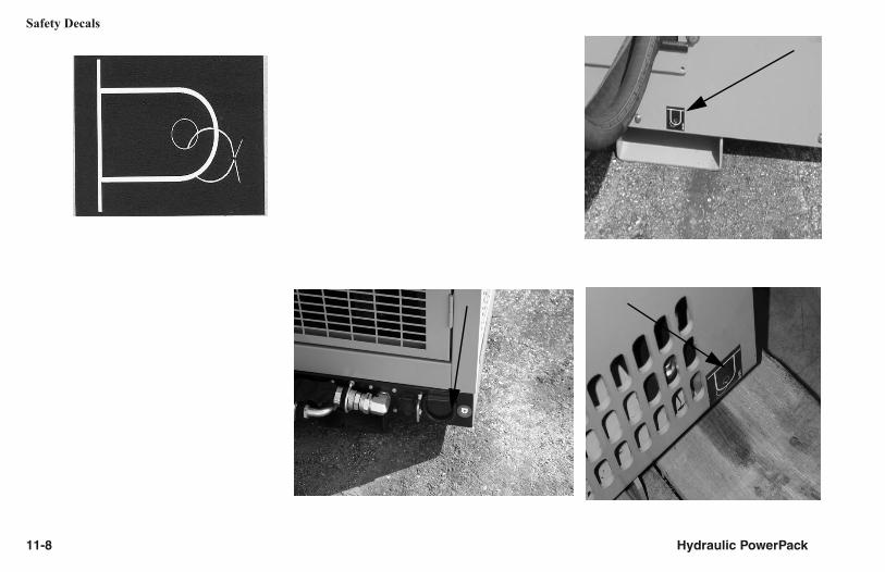
Section 11: Safety DecalsSAFETY DECAL MAINTENANCE
Safety decals located on your machine contain important and useful information that will help you operate your equipment safely.
To assure that all decals remain in place and in good condition, follow the instructions given below:
• Keep decals clean. Use soap and water - not mineral spirits, abrasive cleaners, or other similar cleaners that will damage the decal.
• Replace any damaged or missing decals. When attaching decals, surface temperature of the mounting surface must be at least 40°F (5°C). The mounting surface must also be clean and dry.
• When replacing a machine component with a decal attached, replace the decal also.
• Replacement decals can be purchased from your HammerHead equipment dealer.

Safety Decals
11-2 Hydraulic PowerPack

Safety Decals
Hydraulic PowerPack 11-3

Safety Decals
11-4 Hydraulic PowerPack

Safety Decals
Hydraulic PowerPack 11-5

Safety Decals
11-6 Hydraulic PowerPack

Safety Decals
Hydraulic PowerPack 11-7
Safety Decals
11-8 Hydraulic PowerPack

Machine Controls
Hydraulic PowerPack 20-1
Section 20: Machine ControlsIMPORTANT: Do not start or operate any machine until the instructions in this manual and the Engine Operator’s Manual supplied by the engine manufacturer have been carefully read and understood.
POWERPACK 73NOTE: The standard power unit includes a Kubota 73 hp (54.4 kW) engine @2600 rpm, hydraulic power on/off switch, two 40-ft hydraulic hoses, two quick connectors, and a 12-volt electrical outlet. Any alternative power unit should have equivalent features, with a required hydraulic power rating of 4600 psi (317 bar), and fluid flow rate of 41 gpm (155 L/min).
(1) Throttle
With center button depressed:Pull knob out . . . . . . . . . . . . . . . . . . . . . . . . . . . . . . . . .increase RPM
Push knob in . . . . . . . . . . . . . . . . . . . . . . . . . . . . . . . . decrease RPM1

Machine Controls
20-2 Hydraulic PowerPack
(2) Ignition Switch
Center position . . . . . . . . . . . . . . . . . . . . . . . . . . . . . . . . . . .engine off
1st position clockwise. . . . . . . . . . . . . . . . . . . . . . . . . . . . . .engine on
Fully clockwise . . . . . . . . . . . . . . . . . . . . . . . . . . . . . . . . .engine start
Fully counterclockwise. . . . . . . . . . . . . . . . . . . . . . . . . glow plugs on
(3) Hydraulic Systems On/Off Switch
Down . . . . . . . . . . . . . . . . . . . . . . . . . . . . . . . . . hydraulic systems off
Up . . . . . . . . . . . . . . . . . . . . . . . . . . . . . . . . . . . hydraulic systems onSwitch must be in OFF (down) position when starting engine.
3
2

Machine Controls
Hydraulic PowerPack 20-3
(4) Oil Pressure Warning Light
On. . . . . . . . . . . . . . . . . . . . . . . . . . . . . . . . . . engine oil pressure low
(5) Coolant Temperature Warning Light
On. . . . . . . . . . . . . . . . . . . . . . . . . . . . . . . . . . . . . engine coolant hot
(6) Alternator Warning Light
On. . . . . . . . . . . . . . . . . . . . . . . . . . . . . . . . . . . . . . . . . . .not charging
(7) Pre-Heat IndicatorWith ignition switch in the GLOW PLUG position:
Yellow . . . . . . . . . . . . . . . . . . . . . . . . . . . . . . . . . . . . . . . . . . . . heating
(8) High Hydraulic Oil Temperature IndicatorOn. . . . . . . . . . . . . . . . . . . . . . . . . . . . . . . . . . . . . . . hydraulic oil hot
(9) Hydraulic Oil Filter Condition IndicatorOn. . . . . . . . . . . . . . . . . . . . . . . . . . . . hydraulic filter flow restricted
4 5 6
7 8 9

Machine Controls
20-4 Hydraulic PowerPack
(10) Pressure GaugeShows hydraulic operating pressure
(11) Pressure ControlRotate Clockwise . . . . . . . . . . . . . . . . . . increase hydraulic pressureRotate Counterclockwise . . . . . . . . . . . decrease hydraulic pressure
(12) Emergency Stop SwitchPull . . . . . . . . . . . . . . . . . . . . . . . . . . . . . . . . . . . . . . . . . . . . . . . . . runPush . . . . . . . . . . . . . . . . . . . . . . . . . . . . . . . . . . . . . . . . . . . . . . . stop
11
12
10

Machine Controls
Hydraulic PowerPack 20-5
POWERPACK PP4000NOTE: The standard power unit includes a Kubota 73 hp (54.4 kW) engine @2200 rpm, hydraulic power on/off switch, two 40-ft hydraulic hoses, two quick connectors, and a 12-volt electrical outlet. Any alternative power unit should have equivalent features, with a required hydraulic power rating of 4100 psi (282 bar), and fluid flow rate of 41 gpm (155 L/min).
(1) Throttle
With center button depressed:Pull knob out . . . . . . . . . . . . . . . . . . . . . . . . . . . . . . . . .increase RPM
Push knob in . . . . . . . . . . . . . . . . . . . . . . . . . . . . . . . . decrease RPM1

Machine Controls
20-6 Hydraulic PowerPack
(2) Ignition Switch
Center position . . . . . . . . . . . . . . . . . . . . . . . . . . . . . . . . . . .engine off
1st position clockwise. . . . . . . . . . . . . . . . . . . . . . . . . . . . . .engine on
Fully clockwise . . . . . . . . . . . . . . . . . . . . . . . . . . . . . . . . .engine start
Fully counterclockwise. . . . . . . . . . . . . . . . . . . . . . . . . glow plugs on
(3) Hydraulic Systems On/Off Switch
Down . . . . . . . . . . . . . . . . . . . . . . . . . . . . . . . . . hydraulic systems off also controls electric throttle (down 1000 rpm, up 2200 rpm) on PP4000
Up . . . . . . . . . . . . . . . . . . . . . . . . . . . . . . . . . . . hydraulic systems onSwitch must be in OFF (down) position when starting engine.
2
3

Machine Controls
Hydraulic PowerPack 20-7
(4) Oil Pressure Warning Light
On. . . . . . . . . . . . . . . . . . . . . . . . . . . . . . . . . . engine oil pressure low
(5) Coolant Temperature Warning Light
On. . . . . . . . . . . . . . . . . . . . . . . . . . . . . . . . . . . . . engine coolant hot
(6) Alternator Warning Light
On. . . . . . . . . . . . . . . . . . . . . . . . . . . . . . . . . . . . . . . . . . .not charging
(7) Pre-Heat IndicatorWith ignition switch in the GLOW PLUG position:
Yellow . . . . . . . . . . . . . . . . . . . . . . . . . . . . . . . . . . . . . . . . . . . . heating
(8) High Hydraulic Oil Temperature IndicatorOn. . . . . . . . . . . . . . . . . . . . . . . . . . . . . . . . . . . . . . . hydraulic oil hot
(9) Hydraulic Oil Filter Condition IndicatorOn. . . . . . . . . . . . . . . . . . . . . . . . . . . . hydraulic filter flow restricted
4 5 6
7 8 9

Machine Controls
20-8 Hydraulic PowerPack
(10) Pressure GaugeShows hydraulic operating pressure
(11) Pressure ControlUp . . . . . . . . . . . . . . . . . . . . . . . . . . . . . . increase hydraulic pressureDown . . . . . . . . . . . . . . . . . . . . . . . . . . . decrease hydraulic pressure
(12) Emergency Stop SwitchPull . . . . . . . . . . . . . . . . . . . . . . . . . . . . . . . . . . . . . . . . . . . . . . . . . runPush . . . . . . . . . . . . . . . . . . . . . . . . . . . . . . . . . . . . . . . . . . . . . . . stop
11
10 12

Machine Controls
Hydraulic PowerPack 20-9
POWERPACK 20NOTE: The standard power unit includes a Kubota 20.3 hp (15.1 kW) engine, hydraulic power on/off switch, two 25-ft hydraulic hoses, two quick connectors, and a 12-volt electrical outlet. Any alternative power unit should have equivalent features, with a required hydraulic power rating of 3000 psi, and fluid flow rate of 23-25 gpm (87-94 L/min).
(1) Throttle
With center button depressed:Pull knob out . . . . . . . . . . . . . . . . . . . . . . . . . . . . . . . . .increase RPM
Push knob in . . . . . . . . . . . . . . . . . . . . . . . . . . . . . . . . decrease RPM
1

Machine Controls
20-10 Hydraulic PowerPack
(2) Ignition Switch
Center position . . . . . . . . . . . . . . . . . . . . . . . . . . . . . . . . . . .engine off
1st position clockwise. . . . . . . . . . . . . . . . . . . . . . . . . . . . . .engine on
Fully clockwise . . . . . . . . . . . . . . . . . . . . . . . . . . . . . . . . .engine start
Fully counterclockwise. . . . . . . . . . . . . . . . . . . . . . . . . glow plugs on
(3) Hydraulic Systems On/Off Switch
Down . . . . . . . . . . . . . . . . . . . . . . . . . . . . . . . . . hydraulic systems off
Up . . . . . . . . . . . . . . . . . . . . . . . . . . . . . . . . . . . hydraulic systems onSwitch must be in OFF (down) position when starting engine.
2 3

Machine Controls
Hydraulic PowerPack 20-11
(4) Oil Pressure Warning Light
On. . . . . . . . . . . . . . . . . . . . . . . . . . . . . . . . . . engine oil pressure low
(5) Coolant Temperature Warning Light
On. . . . . . . . . . . . . . . . . . . . . . . . . . . . . . . . . . . . . . engine coolant hot
(6) Alternator Warning Light
On. . . . . . . . . . . . . . . . . . . . . . . . . . . . . . . . . . . . . . . . . . .not charging
(7) Pre-Heat IndicatorWith ignition switch in the GLOW PLUG position:
Yellow . . . . . . . . . . . . . . . . . . . . . . . . . . . . . . . . . . . . . . . . . . . . heating
(8) High Hydraulic Oil Temperature IndicatorOn. . . . . . . . . . . . . . . . . . . . . . . . . . . . . . . . . . . . . . . hydraulic oil hot
(9) Hydraulic Oil Filter Condition IndicatorOn. . . . . . . . . . . . . . . . . . . . . . . . . . . . hydraulic filter flow restricted
4 5 6
7 8 9

Machine Controls
20-12 Hydraulic PowerPack
(10) Pressure GaugeShows hydraulic operating pressure
(11) Pressure ControlRotate Clockwise . . . . . . . . . . . . . . . . . . increase hydraulic pressureRotate Counterclockwise . . . . . . . . . . . decrease hydraulic pressure
(12) Emergency Stop SwitchPull . . . . . . . . . . . . . . . . . . . . . . . . . . . . . . . . . . . . . . . . . . . . . . . . . runPush . . . . . . . . . . . . . . . . . . . . . . . . . . . . . . . . . . . . . . . . . . . . . . . stop
11
10
12

Machine Controls
Hydraulic PowerPack 20-13
POWERPACK 13ANOTE: The PowerPack 13A’s hydraulic pump capacity is less than that of the larger powerpacks. The shuttle speed and maximum sustained pressure output will be less than that of the larger powerpack. This will translate into slower production rates.
On/Off Switch
The on/off switch (1) is located under the fuel tank mounted to the side engine cover.
NOTE: The engine is equipped with a low oil automatic shutdown module. If the unit will not start or shuts down immediately after starting, check the engine oil level.
Fuel Valve Lever
The fuel valve (3) opens and closes the fuel path from the fuel tank to the carburetor. The fuel valve lever must be in the ON position for the engine to run. When the engine is not in use, place the fuel valve lever in the OFF position to prevent the possibility of fuel leakage and carburetor flooding.
Choke Lever
The choke lever (2) opens and closes the choke valve in the carburetor. The CLOSED position enriches the air/fuel mixture to aid in starting a cold engine. The OPEN position provides the correct air/fuel mixture for operation after the engine has been started or for restarting a warm engine. 3
2
1
1

Machine Controls
20-14 Hydraulic PowerPack
Throttle Lever
The throttle lever (4) Controls engine speed. Moving the throttle lever to the left will increase engine speed. Moving the lever to the right will decrease engine speed.
Recoil Starter
Pulling the starter grip (5) operates the recoil starter to spin the crankshaft and start the engine.
4
5

Machine Controls
Hydraulic PowerPack 20-15
Control Stand Assembly
(1) Pressure GaugeShows hydraulic operating pressure
(2) Direction ControlPush In . . . . . . . . . . . . . . . . . . . . extends main cylinder (pulls cable)Pull Out. . . . . . . . . . . . . . . . . . . . . . . . . . . . . . retracts main cylinder Centered . . . . . . . . . . . . . . . . . . . . . . . . . neutral or starting position
1
2

This page intentionally left blank.

Starting Procedure
Hydraulic PowerPack 21-1
Section 21: Starting Procedure
WARNING: The instructions in this section are a brief description of the starting procedures for the HammerHead line of hydraulic powerpacks. For detailed instructions, please read the Hydraulic Power Pack Operator Manual before attempting to run the equipment.
POWERPACK 73IMPORTANT: To avoid engine component damage:
• Do not use ether or other starting fluids.
• Do not turn on pre-heat system on for more than 15 seconds at a time.
• Never run the starter motor for more than 15 seconds at a time. Allow the starter motor to cool 1 minute between attempts.
• Place the softstart switch in the down position. The engine will not start if the switch is in the up position or if the emergency stop button is pressed.
NOTE: The motor has a built in Low Oil Pressure timer circuit which prevents the engine from starting if it has not started after 15 seconds. The ignition key must be placed in the off position to reset the timer before attempting to restart the motor.
Step 1: Set the throttle to 1/4 out.
Step 2: On a cold engine, turn on pre-heat system (5 seconds above freezing, 10 seconds below freezing).

Starting Procedure
21-2 Hydraulic PowerPack
Step 3: Start the engine. If it doesn't start within 15 seconds, wait 1 minute, reset the ignition switch and use the pre-heat system again.
Step 4: Slowly move the throttle to idle and allow engine to warm up.
Step 5: Connect the hydraulic hoses to the slave machine.
Step 6: Place hydraulic on/off switch (1) into the run or up position.
Step 7: Set operating pressure using pressure adjustment knob (2).
POWERPACK PP4000IMPORTANT: To avoid engine component damage:
• Do not use ether or other starting fluids.
• Do not turn on pre-heat system on for more than 15 seconds at a time.
• Never run the starter motor for more than 15 seconds at a time. Allow the starter motor to cool 1 minute between attempts.
• Place the softstart switch in the down position. The engine will not start if the switch is in the up position or if the emergency stop button is pressed.
NOTE: The motor has a built in Low Oil Pressure timer circuit which prevents the engine from starting if it has not started after 15 seconds. The ignition key must be placed in the off position to reset the timer before attempting to restart the motor.
Step 1: Set the throttle to 1/4 out.
Step 2: On a cold engine, turn on pre-heat system (5 seconds above freezing, 10 seconds below freezing).
1 2

Starting Procedure
Hydraulic PowerPack 21-3
Step 3: Start the engine. If it doesn't start within 15 seconds, wait 1 minute, reset the ignition switch and use the pre-heat system again.
Step 4: Slowly move the throttle to idle and allow engine to warm up.
Step 5: Connect the hydraulic hoses to the slave machine.
Step 6: Place hydraulic on/off switch (1) into the run or up position.
POWERPACK 20
STARTING THE ENGINE (SERIAL NUMBER 10014 AND LOWER)IMPORTANT: To avoid engine component damage:
• Do not use ether or other starting fluids.
• Shut off pre-heat system when indicator glows a dull red. Do not turn pre-heat system on for more than 15 seconds at a time.
• Never run the starter motor for more than 15 seconds at a time. Allow the starter motor to cool 1 minute between attempts.
• Connect hydraulic hoses to each other or to the down-hole unit before starting the engine.
Step 1: Set the throttle to 1/2 throttle.
Step 2: On a cold engine, turn on pre-heat system until the indicator glows (approximately 15 seconds).
1
2
1

Starting Procedure
21-4 Hydraulic PowerPack
Step 3: Start the engine. If it doesn't start within 15 seconds, use the pre-heat system again.
Step 4: Slowly move the throttle to idle and allow engine to warm up.
STARTING THE ENGINE (SERIAL NUMBER 10015 AND HIGHER)IMPORTANT: To avoid engine component damage:
• Do not use ether or other starting fluids.
• Do not turn pre-heat system on for more than 15 seconds at a time.
• Never run the starter motor for more than 15 seconds at a time. Allow the starter motor to cool 1 minute between attempts.
• Place the hydraulic on/off switch in the down position. The engine will not start if the switch is in the up position or if the emergency stop button is pressed.
NOTE: The motor has a built in Low Oil Pressure timer circuit which prevents the engine from starting if it has not started after 15 seconds. The ingnition key must be placed in the off position to reset the timer before attempting to restart the motor.
Step 1: Set the throttle to 1/4 out.
Step 2: On a cold engine, turn on pre-heat system (5 seconds if above freezing, 10 seconds if below freezing).
Step 3: Start the engine. If it doesn't start within 15 seconds, reset the ignition switch and use the pre-heat system again.
Step 4: Slowly move the throttle to idle and allow engine to warm up.
Step 5: Connect the hydraulic hoses to the slave machine.
Step 6: Pull throttle out completely.
Step 7: Place hydraulic on/off switch (1) into the run or up position.

Starting Procedure
Hydraulic PowerPack 21-5
Step 8: Set operating pressure using pressure adjustment knob (2).
POWERPACK 13AIMPORTANT: To avoid engine component damage:
• Do not use ether or other starting fluids.
• Connect hydraulic hoses to each other or to the PB30 before starting the system.
Step 1: Turn On/Off Switch to On position
Step 2: Set the throttle to 1/4 open from low idle.
Step 3: On a cold engine slide the choke lever see Choke Lever, page 20-13
Step 4: Open fuel valve.
Step 5: Pull starter rope until engine starts.
Step 6: Allow the engine to warm up.
COLD WEATHER STARTING
Engine
Before operating in cold weather, it is important to use the recommended engine oil viscosity and fuel to reduce starting problems. Refer to the Engine Manual for recommended engine oil, fuel, and starting procedures.

Starting Procedure
21-6 Hydraulic PowerPack
IMPORTANT: Do not spray starting fluid into the air cleaner. Engine damage can result.
Hydraulic Fluid
Allow adequate time for the hydraulic fluid to warm up. Refer to the Specifications section in the Maintenance Manual for recommended hydraulic fluids.
For frequent starts below 10°F (-12°C), consult your HammerHead dealer.
JUMP-STARTING
Battery Explosion - Avoid
WARNING: Battery fumes are flammable and can explode. Keep all burning materials away from battery. Do not smoke. Tools and cable clamps can make sparks. Shield eyes and face from battery.
Do not jump-start or charge a battery that is frozen or low on electrolyte.
Avoid explosion hazard. Battery caps must be in place and tight on all batteries.
IMPORTANT: Use only a 12-volt system for jump-starting. Do not allow vehicles to touch.

Starting Procedure
Hydraulic PowerPack 21-7
Battery Burns - Avoid
Battery contains sulfuric acid which can cause severe burns. Avoid contact with eyes, skin, and clothing.
In case of acid contact:
External: Flush with plenty of water. If eyes have been exposed, flush with water for 15 minutes and get prompt medical attention.
Internal: Drink large quantities of water or milk, follow with milk of magnesia, beaten egg, or vegetable oil. Call a physician immediately.
Jump-Starting Procedure
Step 1: Turn ignition key OFF. Remove battery access panel.
Step 2: Connect jumper cables in the following order:
a. Red to discharged battery POSITIVE (+) terminal (1).
b. Red to boost battery POSITIVE (+) terminal (2).
c. Black to boost battery NEGATIVE (-) terminal (3).
d. Black to frame (4) of machine with the discharged battery. Make connection away from battery.
NOTE: To avoid sparks near the battery, always disconnect black jumper cable at point (4) before making any adjustment to the red jumper cable at point (1).
Step 3: Start engine.
Step 4: Remove cables in REVERSE order and install cover over POSITIVE cable clamp. Install battery access cover.
DISCHARGEDBATTERY
BLACK
BOOSTBATTERY
MACHINEFRAME
RED

This page intentionally left blank.

Shutdown Procedure
Hydraulic PowerPack 22-1
Section 22: Shutdown ProcedureSTOPPING THE MACHINE
When shutting off the engine, use the following shutdown procedure:
• Shut off hydraulics.
• Reduce engine speed to idle.
• Shut the engine off and remove the key.
For your safety and the safety of others, use the shutdown procedure before servicing, cleaning, inspecting, or transporting the machine.
A variation of the above procedure may be used if instructed within this manual or if an emergency requires it.
NOTE: If disconnecting the hoses from the quick couplers, cycle the control valve to relieve hydraulic pressure. It will be hard to reconnect the hoses if there is hydraulic pressure in the system.

This page intentionally left blank.

Preparing Machine and Work Area
Hydraulic PowerPack 30-1
Section 30: Preparing Machine and Work AreaPERSONAL PROTECTIVE EQUIPMENT
Operating the machine will require you to wear protective equipment. You should always wear a hard hat, work shoes and eye protection. Wear leather gloves when handling rods or wire rope. If working near traffic, wear high visibility clothes.
PIT PREPARATION
WARNING: Do not work in trench with unstable side which could cave in. Specific requirements for shoring or sloping trench walls are avaialble from several sources including federal and state OSHA offices. Be sure to contact suitable authorities for these requirements before working in a trench.
If entry into a confined space is necessary, follow all regulations and requirements for working in confined spaces to ensure a hazard-free environment.

Preparing Machine and Work Area
30-2 Hydraulic PowerPack
NOTE: The down-hole unit is located in the exit pit; the pipe is pulled in from the entry pit.
Entry Pit
Uncover the end of the service being replaced. Make the pit large enough the new pipe can make a gentle bend into the old service.
NOTE: It is imperitive that the new pipe enter the old utility as flat or as on grade as possible. Failure to do so will cause the first few feet of the utility to be above grade. It may also create additional friction on the new pipe as it enters the old utility.
The rule of thumb for the entrance pit is that the length of the pit is normally 2-1/2 times the depth of the existing service. Larger diameters and/or lower SDR specifications (thicker walls) will require longer entrance pits to accomodate the larger bend radious of the pipe.
Exit Pit - HB3038/HB5058
• Uncover the end of the service being replaced. The pipe puller and spacer require a 1-1/2 ft by 9 ft (46 cm by 274 cm) pit. Add enough extra room so the operator can manuver safely.
• Slope, terrace or shore the trench to avoid cave ins.
NOTE: The centerline of the rods is 6-1/2" (16.5 cm) above the surface on which the down-hole unit sits.
• Slope the floor of the pit to the grade of the burst and square the face of the pit.
• It may be helpful to place two 2 x 8’s aproximately 90" (230 cm) long in the pit. Planks or timbers can also be placed on the face ofe pit to distribute the pullback force over a larger area.
• Some situations may require other procedures, such as dewatering or bypass pumping.
Exit Pit - HB100T
• Uncover the end of the service being replaced. The pipe puller and spacer brace require a 3 ft by 10-1/2 ft (91 cm by 320 cm) pit. Add enough extra room so the operator can manuver safely.
Preparing Machine and Work Area
Hydraulic PowerPack 30-3
• Slope, terrace or shore the trench to avoid cave-ins.
NOTE: The centerline of the rods is 14-1/4" (36.2 cm) above the surface on which the down-hole unit sits.
• Slope the floor of the pit to the grade of the burst and square the face of the pit.
• Square the face of the exit pit to the face of the HB100T.
• Prepare the pit by stabilizing the bottom of the pit with a layer of gravel, Further stabilization can be accomplished by placing a road plate on top of the gravel before setting the machine in place.
Exit Pit - HB125
• Uncover the end of the service being replaced. The pipe puller and spacer brace require a 4 ft by 10-1/2 ft (1.2 m by 3.2 m) pit. Add enough extra room so the operator can manuver safely.
• Slope, terrace or shore the trench to avoid cave-ins.
NOTE: The centerline of the rods is 18" (45.7 cm) above the surface on which the down-hole unit sits. Therefore the pit must be at least 18" deeper than the existing utiltiy measured from the centerline of the existing utility.
• Slope the floor of the pit to the grade of the burst and square the face of the pit. Exact adjustments can be made with the verticle stabilizers on the HB125 if the option has been installed on the unit.
• Square the face of the exit pit to the face of the HB125.
• Prepare the pit by stabilizing the bottom of the pit with a layer of gravel, Further stabilization can be accomplished by placing a road plate on top of the gravel before setting the machine in place.

Preparing Machine and Work Area
30-4 Hydraulic PowerPack
EQUIPMENT PLACEMENT AND INSTALLATION
WARNING: Never lift equipment over personnel. The load may fall or shift, crushing anyone beneath it
Set the unit up in a safe and efficient working position. If setting up near traffic, use the necessary warning and diversion systems for motor vehicles and pedestrian traffic. Use the necessary signs, cones and flag personnel for the work situation.
PowerPack PP73
Step 1: Attach lifting chains to lifting point (1) and use a hoist, or use a fork lift in tubes (2), to place the powerpack near the exit pit - close enoughthat the 40 ft (12.2 m) hoses will (3)will reach the down hole unit.
Step 2: Connect hoses (3) to quick couplerson the down-hole unit.
2
31

Preparing Machine and Work Area
Hydraulic PowerPack 30-5
PowerPack PP4000
Step 1: Attach lifting chains to lifting point (1) and use a hoist, or use a fork lift in tubes (2), to place the powerpack near the exit pit - close enoughthat the 40 ft (12.2 m) hoses will (3)will reach the down hole unit.
Step 2: Connect hoses (3) to quick couplerson the down-hole unit.
PowerPack PP20
Step 1: Attach lifting chains to lifting point (1) and use a hoist, or use a fork lift in tubes (2), to place the powerpack near the exit pit - close enoughthat the 25 ft (7.6 m) hoses will (3)will reach the down hole unit.
Step 2: Connect hoses to quick couplerson the down-hole unit.
IMPORTANT: The hoses must be connected to each other or to the downhole unit before starting the unit
3 1
2
2
1

Preparing Machine and Work Area
30-6 Hydraulic PowerPack
PowerPack PP13A
Step 1: Place the Control Station (1) near the exit pit - close enough that the operator has a clear, unobstructed view of the downhole unit.
Step 2: Place the PP13A (2) as far away from the edge of the exit pit as possible while still having the hoses close enough to attach to the control station.
Step 3: Connect the hoses from the down-hole unit to the control station.
IMPORTANT: The hoses must be connected to each other or to the control station before attempting to start the engine.
1
2

Maintenance Intervals
Hydraulic PowerPack 50-1
Section 50: Maintenance Intervals
WARNING: Before servicing, cleaning, repairing, inspecting, lubricating, fueling, or transporting the machine, refer to the Shutdown Procedure, page 22-1, for proper instructions.
HOURMETER - CHECK FOR MAINTENANCE INTERVAL
The hourmeter on the power unit is used to determine maintenance intervals for the machine. The hourmeter indicates the total number of hours the engine has been in operation.
The PowerPack 13 does not have an hourmeter attached to the unit. Hours of use, therefore, must be tabulated by noting the amount of time the unit is in operation.
Maintenance intervals are based on normal operating conditions. When operating under severe conditions, the maintenance intervals should be shortened.

This page intentionally left blank.

Maintenance - 10 Service Hours or Daily
Hydraulic PowerPack 51-1
Section 51: Maintenance - 10 Service Hours or Daily
WARNING: Before servicing, cleaning, repairing, inspecting, lubricating, fueling, or transporting the machine, refer to the Shutdown Procedure, page 22-1, for proper instructions.
FLUID LEVELS - CHECK
Check fluid levels daily before operating the machine. Also inspect the machine and make any necessary adjustments and repairs before starting the engine.
Engine Coolant Level
WARNING: Do not remove radiator cap from a hot engine. Wait until the temperature has cooled before removing the pressure cap. Failure to do so can result in personal injury from heated coolant spray or steam. Remove the filler cap slowly to relieve coolant system pressure.
Fill to within 1/2" (13 mm) of the bottom of the fill pipe with a low-silicate (ethylene-glycol) antifreeze and clean water mixture.
NOTE: Never add pure antifreeze to a cooling system. We recommend using a 50/50 mixture. Never use high-silicate antifreeze or antifreeze that is higher than 60/40 mixture.

Maintenance - 10 Service Hours or Daily
51-2 Hydraulic PowerPack
1
Crankcase Oil Level
PP73/4000
With engine level, fill to full mark on dipstick (1). Do not overfill.
11
PP20PP4000 PP13

Maintenance - 10 Service Hours or Daily
Hydraulic PowerPack 51-3
Hydraulic Fluid Level
CAUTION: Clean hydraulic fluid is very important so do not spill dirt or other contaminants into the tank. Filter all hydraulic fluid through a 10-micron filter before adding it to the tank.
NOTE: The hydraulic fluid must be free of bubbles. Bubbles indicate trapped air in the hydraulic system.
(1) Fill Cap
1
PP13APP20PP73/4000
1 1

Maintenance - 10 Service Hours or Daily
51-4 Hydraulic PowerPack
Fuel Tank - Fill
WARNING: Never refuel machine while smoking or with engine running. Fill fuel tank outdoors. Clean up spilled fuel. Do not allow any hot or burning material near the machine.
Fill the fuel tank at the end of each day to prevent condensation. Do not fill tank to the very top, leave room for expansion.
(1) Fill Cap
1 1
PP73 PP20 PP13APP4000
1

Maintenance - 50 Service Hours or Weekly
Hydraulic PowerPack 52-1
Section 52: Maintenance - 50 Service Hours or WeeklyENGINE MAINTENANCE
• Initial engine oil change
• Initial engine oil filter change
• Initial fan and alternator belt tension check
Refer to Maintenance - 100 Service Hours, page 53-1.
AIR CLEANER - SERVICE
In dusty conditions, the element must be cleaned more often.
Clean the element by tapping lightly on its edge or by using compressed air on the inside walls.
Use caution when using compressed air. Damage may occur if air nozzle is too close to element.
Replace the element after 6 cleanings or every 300 service hours, whichever comes first.

This page intentionally left blank.

Maintenance - 100 Service Hours
Hydraulic PowerPack 53-1
Section 53: Maintenance - 100 Service Hours ENGINE OIL AND FILTER - CHANGE
Step 1: Set the power unit on suitable blocking and place a container underneath hole (1).
Step 2: Remove drain plug on bottom of oil pan and drain warm oil into the container. Install and tighten plug.
Step 3: Remove oil filter (2).
Step 4: Clean the filter head surface.
Step 5: Apply a thin film of oil to gasket of new filter.
Step 6: Install filter and tighten until gasket contacts filter head, then tighten 3/4 turn more.
Step 7: Add oil to the full mark on the dipstick.
Step 8: Run the engine several minutes, follow shutdown procedure, and recheck oil level.
PP13A
PP20PP73/4000
1
2
2
1
1

Maintenance - 100 Service Hours
53-2 Hydraulic PowerPack
ENGINE FAN AND ALTERNATOR BELT - CHECK
Check tension:
The belt is correctly tensioned when 2.2 lb (1 kg) is applied to the center of the span, and the belt deflects 0.16˝ (4 mm).
Loosen bolts (1) to adjust belt.
Check belt wear:
Check fan and alternator belt for cracks, breaks, and proper adjustment. Replace when necessary.
To replace belt:
Step 1: Loosen bolts (1).
Step 2: Remove belt and install new belt.
Step 3: Adjust belt tension.
NOTE: Dispose of fluids per local laws and ordinances.
1
1
PP20
PP73/4000

Maintenance - 100 Service Hours
Hydraulic PowerPack 53-3
COOLING SYSTEM - CHECK
• Inspect hose clamps and overflow tube.
• Check for dirt and debris in radiator fins.
• Check fan for cracks, loose rivets and bent or loose blades.
HYDRAULIC FLUID FILTER - CHANGE
The hydraulic fluid filter element on a new machine needs to be changed after the first 100 service hours of operation and every 500 service hours thereafter. To change filter element, refer to the Maintenance - 500 Service Hours section, “Hydraulic Fluid Filter - Change,” page 55-4, for proper procedure.
HYDRAULIC SYSTEM - CHECK
WARNING: Pressurized fluid can penetrate body tissue and result in serious injury or death. Leaks can be invisible. Relieve pressure before working on system. When searching for a leak, use an object like cardboard - not your hand. Fluid injected under the skin must be removed immediately by a surgeon familiar with this type of injury.
Check hydraulic system for leaks, kinked hoses, and hoses or other parts that rub against each other.

Maintenance - 100 Service Hours
53-4 Hydraulic PowerPack
OVERALL MACHINE - CHECK
Shields and Guards - Check that all shields and guards are installed and are fastened securely to the machine. Replace or repair any shields or guards that are damaged or have missing parts.
Decals - Check the machine for any worn or missing safety and operating decals. (Refer to Safety Decals, page 11-1, and Machine Controls, page 20-1.)
Hardware - Check the machine for loose, worn, or missing parts and hardware. Tighten any loose parts and replace any worn or missing parts (refer to Parts Manual for replacement parts).
Frame - check frame and contact dealer immediately if you notice any bending or cracking.

Maintenance - 200 Service Hours
Hydraulic PowerPack 54-1
Section 54: Maintenance - 200 Service Hours COOLING SYSTEM ADDITIVE - ADD
WARNING: Do not remove radiator cap from a hot engine. Wait until the temperature has cooled before removing the pressure cap. Failure to do so can result in personal injury from heated coolant spray or steam. Remove the filler cap slowly to relieve coolant system pressure.
Add 1 oz (29.6 cc) of Fleetguard DCA4 to coolant system to prevent electrolysis.

Maintenance - 200 Service Hours
54-2 Hydraulic PowerPack
FUEL FILTER - REPLACE
WARNING: Keep heat, flames, and sparks away from fuel. Always clean up spilled fuel.
To replace:
Step 1: Clean outside surfaces of filter assembly (1).
Step 2: Place tray under the filter to catch spilled fuel.
Step 3: Remove the filter with a filter wrench.
Step 4: Fill new filter with clean fuel. Allow enough time for fuel to pass through the element.
Step 5: Apply a thin film of oil to gasket of new filter.
Step 6: Install filter and tighten until gasket contacts filter head, then tighten 3/4 turn more.
PP73/4000
1
PP20
1

Maintenance - 500 Service Hours
Hydraulic PowerPack 55-1
Section 55: Maintenance - 500 Service Hours COOLING SYSTEM - DRAIN AND CLEAN
WARNING: Do not remove radiator cap from a hot engine. Wait until the temperature has cooled before removing the pressure cap. Failure to do so can result in personal injury from heated coolant spray or steam. Remove the filler cap slowly to relieve coolant system pressure.
Step 1: Drain the old coolant from the system.
Step 2: Fill radiator with clean water. Check for signs of rust and add a cooling system cleaner to the water if necessary.
Step 3: Run the engine long enough to be sure thermostat has opened, allowing the engine and radiator to receive fresh water. Allow the system to cool, then drain the water.
Step 4: Add a 50/50 mixture of low-silicate ethylene glycol antifreeze and clean water to the radiator. Do not fill completely. Run the engine until mixture has circulated in the system.
Step 5: Add 4 oz (120 cc) of Fleetguard DCA4. Finish filling radiator. System capacity is approximately 1 gal (3.8 L).
Recheck radiator after engine has cooled overnight. Fill as necessary. Continue to check each time machine is run and cooled off until radiator remains full.

Maintenance - 500 Service Hours
55-2 Hydraulic PowerPack
BATTERY ELECTROLYTE LEVEL AND TERMINALS - CHECK
WARNING: Battery contains highly explosive hydrogen gas.
Battery contains sulfuric acid which can cause severe burns.
• Wear safety glasses or face shield and rubber gloves.
• Use a flashlight to check electrolyte level.
• Work in a well-ventilated area.
• Avoid breathing fumes from battery.
• Avoid contact with skin, eyes, or clothing.
• Keep flame and sparks away, and do not smoke.
• Keep out of reach of children.
• Do not short across battery terminals or allow tools to short from battery terminals to frame.
• Do not jump-start or charge a battery with frozen electrolyte.
In case of acid contact:
EXTERNAL: Flush with plenty of water. If eyes have been exposed, flush with water for 15 minutes and get prompt medical attention.
INTERNAL: Drink large quantities of water or milk, follow with milk of magnesia, beaten egg, or vegetable oil. Call a physician immediately.

Maintenance - 500 Service Hours
Hydraulic PowerPack 55-3
Terminals - Clean
Electrolyte Level - Check
Step 1: Open side access door.
Step 2: Remove black negative (-) cable then red positive (+) cable.
Step 3: Remove battery bracket (1) and battery.
Step 4: Clean terminals and clamps with a stiff wire brush.
Step 5: Apply a light coating of petroleum jelly around the base of each terminal.
Step 6: Remove cell caps (2); fill each cell with distilled water (never add acid); then replace cell caps.
IMPORTANT: In freezing weather, run the engine immediately after filling the battery to allow water and electrolyte to mix.
Step 7: Install battery and bracket (1).
Step 8: Install the red positive (+) cable then the black negative (-) cable.
Step 9: Close side access panel.
21 21
Maintenance - 500 Service Hours
55-4 Hydraulic PowerPack
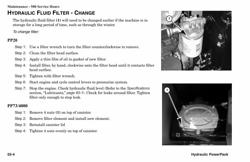
HYDRAULIC FLUID FILTER - CHANGE
The hydraulic fluid filter (1) will need to be changed earlier if the machine is in storage for a long period of time, such as through the winter.
To change filter:
PP20
Step 1: Use a filter wrench to turn the filter counterclockwise to remove.
Step 2: Clean the filter head surface.
Step 3: Apply a thin film of oil to gasket of new filter.
Step 4: Install filter, by hand, clockwise onto the filter head until it contacts filter head surface.
Step 5: Tighten with filter wrench.
Step 6: Start engine and cycle control levers to pressurize system.
Step 7: Stop the engine. Check hydraulic fluid level (Refer to the Specifications section, “Lubricants,” page 60-1). Check for leaks around filter. Tighten filter only enough to stop leak.
PP73/4000
Step 1: Remove 4 nuts (1) on top of canister.
Step 2: Remove filter element and install new element.
Step 3: Reinstall canister lid
Step 4: Tighten 4 nuts evenly on top of canister.
1
1

Maintenance - 500 Service Hours
Hydraulic PowerPack 55-5
PP13
Step 1: Use a filter wrench to turn the filter cap (1) counterclockwise to remove.
Step 2: Grab tab (2) on top of filter and gently pull filter assembly out.
Step 3: Hold bottom of filter assembly pull filter from lower assembly.
NOTE: Dispose of fluids and filter per local laws and ordinances.
1
2
3

Maintenance - 500 Service Hours
55-6 Hydraulic PowerPack
Step 4: Install filter and seat into lower part of assembly (4).
Step 5: Push assembly into hydraulic tank (5).
Step 6: Make sure o-ring seal (6) is in place and apply a thin film of oil to the rubber o-ring.
4
5
6
Maintenance - 500 Service Hours
Hydraulic PowerPack 55-7
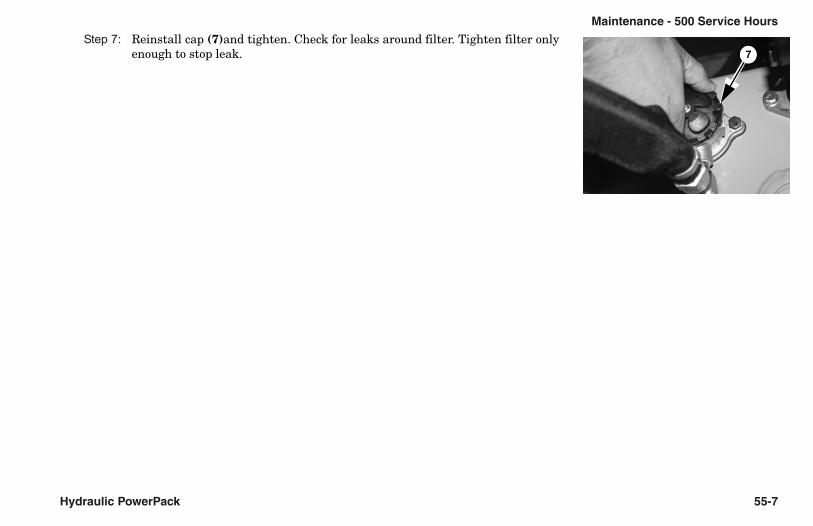
Step 7: Reinstall cap (7)and tighten. Check for leaks around filter. Tighten filter only enough to stop leak. 7

This page intentionally left blank.

Maintenance - 1000 Service Hours
Hydraulic PowerPack 56-1
Section 56: Maintenance - 1000 Service Hours HYDRAULIC FLUID - CHANGE
PP73/4000
If the fluid smells burned, contains air bubbles, or appears contaminated, consult HammerHead dealer immediately.
Step 1: When oil is warm, remove fill cap (1) and drain plug (2). Drain fluid into a suitable container.
Step 2: Clean, inspect, and install drain plug.
Step 3: Change the hydraulic filter(s) (refer to the Maintenance - 500 Service Hours section, “Hydraulic Fluid Filter - Change,” page 55-4).
Step 4: Inspect the hydraulic strainer (refer to next page).
Step 5: Refer to the Specifications section, “Lubricants,” page 60-1, for approved oils and fill hydraulic fluid tank.
Step 6: Operate the hydraulic system.
Step 7: Follow the Shutdown Procedure, page 22-1, and recheck oil level.
1
2

Maintenance - 1000 Service Hours
56-2 Hydraulic PowerPack
PP20
Step 1: When oil is warm, remove fill cap (1) and drain plug (2). Drain fluid into a suitable container.
Step 2: Clean, inspect, and install drain plug located under the hydraulic reservoir.
Step 3: Change the hydraulic filter(s) (refer to the Maintenance - 500 Service Hours section, “Hydraulic Fluid Filter - Change,” page 55-4).
Step 4: Inspect the hydraulic strainer (refer to next page).
Step 5: Refer to the Specifications section, “Lubricants,” page 60-1, for approved oils and fill hydraulic fluid tank.
Step 6: Operate the hydraulic system.
Step 7: Follow the Shutdown Procedure, page 22-1, and recheck oil level.
1
2

Maintenance - 1000 Service Hours
Hydraulic PowerPack 56-3
PP13
Step 1: When oil is warm, remove fill cap (1) and drain plug (2). Drain fluid into a suitable container.
Step 2: Clean, inspect, and install drain plug located under the hydraulic reservoir.
Step 3: Change the hydraulic filter(s) (refer to the Maintenance - 500 Service Hours section, “Hydraulic Fluid Filter - Change,” page 55-4).
Step 4: Inspect the hydraulic strainer (refer to next page).
Step 5: Refer to the Specifications section, “Lubricants,” page 60-1, for approved oils and fill hydraulic fluid tank.
Step 6: Operate the hydraulic system.
Step 7: Follow the Shutdown Procedure, page 22-1, and recheck oil level.
1
2

Maintenance - 1000 Service Hours
56-4 Hydraulic PowerPack
HYDRAULIC FLUID STRAINER - INSPECT
Check strainer when you change the hydraulic fluid. Use the following steps after draining the tank:
Step 1: Disconnect hose (1) and place end in bucket to catch hydraulic fluid.
Step 2: Turn strainer (2) counterclockwise and remove it from tank.
Step 3: Clean the strainer with a petroleum base paint thinner or other good cleaning solvent. Scrub the strainer with a small soft-bristled brush. Look for lacquers which may have formed as a result of hot spots in the hydraulic system.
WARNING: Wear proper clothing, including a face shield, when using compressed air to clean or dry solvent-coated parts.
Step 4: Rinse the strainer with clean solvent or thinner. Use compressed air to blow it clean.
Step 5: Use a suitable thread sealant such as Loctite Vibra-seal on fitting and strainer.
Step 6: Install and tighten strainer and fitting.
Step 7: Connect and tighten hose.
2
1
1
2
Maintenance - As Required
Hydraulic PowerPack 57-1
Section 57: Maintenance - As RequiredENGINE SYSTEM - CHECK
An Engine Operation Manual is supplied with each machine. Refer to the manual for service requirements.
Refer to the Engine Service Manual or contact your dealer for procedures on the following maintenance items:
Check and adjust idle speed . . . . . . . . . . . . every 100 hours or 3 months
Check injectors for performance . . . . . . . . . . . every 400 hours or yearly
Check and adjust valve clearances . . . . . . every 600 hours or 18 months
Tighten cylinder head bolts . . . . . . . . . . . . every 600 hours or 18 months

Maintenance - As Required
57-2 Hydraulic PowerPack
BATTERY - REPLACE
Replacement batteries must meet standard battery specifications provided in the the Specifications section, “Machine Specifications,” page 60-2.
To replace:
Step 1: Open side access door.
Step 2: Remove black negative (-) cable then red positive (+) cable.
Step 3: Remove battery bracket (1) and battery.
Step 4: Install new battery and bracket.
Step 5: Apply a light coating of petroleum jelly around the base of each terminal.
IMPORTANT: In freezing weather, run the engine immediately after filling the battery to allow water and electrolyte to mix.
Step 6: Install the red positive (+) cable then the black negative (-) cable.
Step 7: Close side access door.
21
21

Specifications
Hydraulic PowerPack 60-1
Section 60: SpecificationsLUBRICANTS
Lubricant Capacity Specification / Notes
Hydraulic Fluid As required Phillips: Type HGISO STD or equivalent
Use caution not to get dirt or other contaminants into the system(s) when connecting with a tractor, or when servicing. Filter all fluid through a 10-micron filter before adding.
Grease As required EP grease or equivalent
To minimize condensation in bearings, grease machine after it is shut down for the day.
Fittings and grease applicator nozzle must be clean before applying grease. Replace all missing fittings.
General Lubricating Oil As required SAE-30, 882 Heavy Moly Lube or equivalent

Specifications
60-2 Hydraulic PowerPack
HYDRAULIC POWERPACK
Specifications PP73 PP4000 PP20 PP13A
Overall Length 72" (182.9 cm) 82.5" (210 cm) 52.5" (133 cm) 34.5" (87.6 cm)
Overall Width 41" (104 cm) 56" (142 cm) 29.3" (74.7 cm) 23.25" (59 cm)
Overall Height 58" (147 cm) 64.5" (164 cm) 41.7" (106 cm) 29.8" (76 cm)
Weight 2,800 lb (1,270 kg) 3200 lb (1451 kg) 690 lb (313 kg) 390 lb (177 kg)
Engine Model Kubota V3300 Kubota V3307T Kubota D905 Honda® GX390
Horsepower73 HP (54.4 kw)
@2,600 rpm72.7 HP (54.2 kw)
@2,300 rpm20.8 HP (15.1 kw)
@3,000 rpm13.0 HP (9.7 kw)
@ 3,600 rpm
Pump Flow41 gpm (155 Lpm)
@2,600 rpm
45.6 gpm (172.6 Lpm)
@2,300 rpm
26 gpm (91 Lpm)@ 3,000 rpm
6 gpm (23 Lpm)@ 3,000 rpm
Sound Level 82 dbA 73 dbA 87.4 dbA
Compatable HalmmerHeadModels
HydroBurst HB125
HydroBurst HB175HydroBurst HB125
HydroBurst HB100THydroBurst HB80
PortaBurst PB30HydroBurst HB3038HydroBurst HB5058
PortaBurst PB30

Hydraulic PowerPack Torque Values 97-1
Section 97: Torque Values
HYDRAULIC FITTINGS
Pipe Thread Fittings
• Ensure all threads are free from nicks, burrs, and dirt.
• Use a thread sealant such as Loctite Vibra-Seal, instead of pipe dope or Teflon tape, to seal the threads. Teflon tape can plug filters and drain orifices, and can cause hydraulic system failures.
• To tighten, turn the fitting approximately three turns past finger tight.

97-2 Torque Values Hydraulic PowerPack
O-Ring Fittings• Ensure the threads and sealing surfaces are free from nicks, burrs, scratches, or any foreign material.
• Lubricate the O-ring with a light coat of oil.
• To tighten adjustable O-ring fittings, hold the fitting and tighten the nut.
• To tighten non-adjustable O-ring fittings, tighten the fitting.
Size Thread Torque
#2 5/16˝ -24 7 - 8 ft-lb (10 - 11 Nm)
#3 3/8˝ -24 14 -16 ft-lb (19 - 21 Nm)
#4 7/16˝ -20 16 - 18 ft-lb (21 - 24 Nm)
#5 1/2˝ -20 22 - 24 ft-lb (29 - 32 Nm)
#6 9/16˝ -18 24 - 26 ft-lb (33 - 35 Nm)
#8 3/4˝ -16 40 - 43 ft-lb (54 - 59 Nm)
#10 7/8˝ -14 68 - 70 ft-lb (93 - 95 Nm)
#12 1-1/16˝ -12 98 - 102 ft-lb (133 - 138 Nm)
#16 1-5/16˝ -12 146 - 154 ft-lb (197 - 209 Nm)

Hydraulic PowerPack Torque Values 97-3
Face Seal Fittings
• Ensure the threads and sealing surfaces are free from nicks, burrs, scratches, or any foreign material.
• Lubricate the o-ring with a light coat of oil.
• To tighten adjustable o-ring fittings, hold the fitting and tighten the nut.Ensure the threads and sealing surfaces are free from nicks, burrs, scratches, or any foreign material.
• To tighten non-adjustable o-ring fitting, tighten the fitting.Ensure the threads and sealing surfaces are free from nicks, burrs, scratches, or any foreign material.
DASH SIZE
Nom Size(IN)
Thread SizeFemale Thread
Male Thread
Steel TorqueRecomendations
(ft. Lbs)
O-Ring
I.D. (In) O.D. (In) Min Max I.D. (In)
- 4 1/4 9/16 - 18 1/2 9/16 18 22 5/16
- 6 3/8 11/16 - 16 11/16 11/16 29 36 3/8
- 8 1/2 13/16 - 16 3/4 13/16 40 50 1/2
- 10 5/8 1 - 14 13/16 1 44 55 5/8
- 12 3/4 1-3/16 - 12 1-7/64 1-3/16 66 82 3/4
- 16 1 1-7/16 - 12 1-23/64 1-7/16 92 115 15/16
- 20 1-1/4 1-11/16 - 12 1-19/32 1-11/16 125 156 1-3/16
- 24 1-1/2 2 - 12 1-59/64 2 147 183 1-1/2

97-4 Torque Values Hydraulic PowerPack
JIC Fittings• Ensure the threads and sealing surfaces are free from nicks, burrs, scratches, or any foreign material.
• To tighten, turn the fitting until finger tight. Then turn the fitting an additional number of flats as indicated on the chart below. One flat equals 1/6 of a turn.
IMPORTANT: Do not overtighten the fitting. If overtightened, the female side of the fitting may deform or break, causing the oil flow to become restricted or a leak to form.
Flats from Finger Tight
Size New Fittings Loose Fittings
#4 (1/4˝) 2 to 2-1/2 3/4 to 1
#6 (3/8˝) 2 to 2-1/4 1
#8 (1/2˝) 1-1/2 to 1-3/4 1
#10 (5/8˝) 1-1/2 to 1-3/4 3/4
#12 (3/4˝) 1-1/2 3/4
#14 (7/8˝) 2 1-1/4
#16 (1˝) 1-1/4 to 1 1/2 3/4 to 1
#20 (1-1/4˝) 1 1/2 3/4 to 1
#24 (1-1/2˝) 1 1/4 to 1 1/2 1 to 1 1/4
#32 (2˝) 1 1/4 3/4 to 1

Hydraulic PowerPack Torque Values 97-5
FASTENERS
For SAE Grade 2, Grade 5, and Grade 8 Cap Screws and Bolts
NOTE: Torque values specified in text take precedence over values shown below. These values do not apply when used with lock nuts.
Grade 2 Grade 5 Grade 8
Bolt Size Ft-Lb Nm Ft-Lb Nm Ft-Lb Nm
1/4˝ -20 NC 4 5 6 8.5 10 13
1/4˝ -28 NF 5 6 8 11 11 15
5/16˝ -18 NC 9 12 13 18 20 27
5/16˝ -24 NF 10 13 15 20.5 22 29.5
3/8˝ -16 NC 16 22 25 35 35 47
3/8˝ -24 NF 18 24 30 40 40 55
7/16˝ -14 NC 25 35 40 55 55 75
7/16˝ -20 NF 30 40 45 60 65 88
1/2˝ -13 NC 40 55 60 80 90 120
1/2˝ -20 NF 45 60 70 95 95 130
9/16˝ -12 NC 55 75 90 120 120 165
9/16˝ -8 NF 60 80 95 130 135 185
5/8˝ -11 NC 75 100 120 165 180 245

97-6 Torque Values Hydraulic PowerPack
5/8˝ -18 NF 80 110 145 200 195 265
3/4˝ -10 NC 130 175 210 285 300 405
3/4˝ -16 NF 145 200 240 325 340 460
7/8˝ -9 NC 150 205 320 435 500 680
7/8˝ -14 NF 170 230 350 475 560 760
1˝ -8 NC 180 245 480 650 800 1085
1˝ -14 NF 200 270 560 760 920 1250
1 1/8˝ -7 NC 240 325 700 950 1180 1600
1 1/8˝ - 2 NF 275 375 780 1060 1340 1815
1 1/4˝ -7 NC 340 460 1020 1385 1720 2330
1 1/4˝ - 2 NF 370 500 1140 1545 1900 2575
1 3/8˝ -6 NC 460 625 1360 1845 2280 3090
1 3/8˝ -12 NF 540 730 1580 2140 2620 3550
1 1/2˝ -6 NC 640 870 1840 2495 3060 4150
1 1/2˝ -12 NF 740 1000 2100 2850 3460 4690
Grade 2 Grade 5 Grade 8

Hydraulic PowerPack Torque Values 97-7
For Metric Grade 5.8, 6.9, 8.8, 10.9, & 12.9 Cap Screws and Bolts
Grade 5.8 Grade 6.9 Grade 8.8 Grade 10.9 Grade 12.9
Bolt Size Ft-Lb Nm Ft-Lb Nm Ft-Lb Nm Ft-Lb Nm Ft-Lb Nm
M4 1.1 1.5 1.7 2.3 2 2.7 2.9 4 3.6 5
M5 2.3 3.1 3.5 4.7 4 5.4 6 8 7 9.5
M6 3.9 5.3 5.8 7.8 7 9.5 10 13.5 11 15
M7 6.5 8.8 9.4 12.7 11 15 16 22 20 27
M8 10 13.5 14 19 18 24 25 34 29 39
M10 20 27 29 39 32 43 47 64 58 79
M12 34 46 50 68 58 79 83 112.5 100 136
M14 54 73 79 107 94 127 133 180 159 216
M16 80 108.5 122 165 144 195 196 266 235 319
M18 114 155 170 230.5 190 258 269 365 323 438
M20 162 220 220 298 260 353 366 496 440 597
M22 202 274 318 431 368 499 520 705 628 852
M24 245 332 410 556 470 637 664 900 794 1077
M27 360 488 606 822 707 959 996 1351 1205 1634
M30 500 678 815 1105 967 1311 1357 1840 1630 2210

97-8 Torque Values Hydraulic PowerPack
For Grade B, C, F, and G Lock Nuts
Grade B(Grade 5)
Grade C(Grade 8)
Grade F(Grade 5 Flange)
Grade G(Grade 8 Flange)
Nut Size Ft-Lb Nm Ft-Lb Nm Ft-Lb Nm Ft-Lb Nm
1/4˝ -20 NC 7.5 - 10 10 - 13 10 - 14 14 - 19 8 - 10 11 - 14 12 - 16 16 - 21.5
1/4˝ -28 NF 8 - 10 11 - 14 10 - 14 14 - 19 9 - 12 12 - 16 12 - 17 16 - 23
5/16˝ -18 NC 14 - 17.5 19 - 24 17.5-22.5 24 - 30.5 15 - 20 20 - 27 19.5 - 27 27 -36
5/16˝ -24 NF 15 - 18 20 - 25 18 - 23 25 - 32 16 - 22 21.5 - 29 19.5 - 26 27 - 35
3/8˝ -16 NC 21 - 27 28.5 - 37 29 - 37 39 - 50 22.5 - 32.5 30.5 - 44 30 - 41 41 - 56
3/8˝ -24 NF 27.5 - 38 37 - 51.5 22.5 - 31 30.5 - 42 23.5 - 31.5 32 - 43 31 - 42 42 - 57
7/16˝ -14 NC 31 - 40 42 - 54 39 - 53 53 - 72 36 - 50 49 - 68 45 - 62 61 - 84
7/16˝ -20 NF 39 - 51 53 - 69 41 - 56 56 - 76 38 - 53 51.5 - 72 51 - 71 69 - 96
1/2˝ -13 NC 49.5 - 62.5 67 - 85 62 - 79.5 84 - 108 50.5 -69.5 68.5 - 94 72 - 102 98 - 132
1/2˝ -20 NF 50 - 65 68 - 88 67 - 87 91 - 118 56.5 -78.5 77 - 106 67 - 106 91 - 144
9/16˝ -12 NC 67 - 87 91 - 118 95 - 120 129 - 163 72 - 102 98 - 132 105 - 145 142 - 197
9/16˝ -18 NF 74.5 - 94.5 101 - 128 95 - 120 129 - 163 79 - 111 107-150.5 113 - 157 153 - 213
5/8˝ -11 NC 95 - 120 129 - 163 125 -157.5 169.5-214 100 - 137 136 - 186 130 - 178 176 - 241
5/8˝ -18 NF 97.5-122.5 132 - 166 125 - 160 169.5 -217 105 - 145 142 - 197 150 - 210 203 - 285
3/4˝ -10 NC 160 - 200 217 - 271 200 - 255 271 - 346 170 - 230 230.5-312 205 - 285 278-386.5

Hydraulic PowerPack Torque Values 97-9
3/4˝ -16 NF 155 - 200 210 - 271 200 - 255 271 - 346 163 - 227 221 - 308 215 - 315 291.5-427
7/8˝ -9 NC 235 - 300 319 - 407 295-382.5 400 - 519
7/8˝ -14 NF 250 - 320 339 - 434 295-382.5 400 - 519
1 -8˝ NC 345 - 445 468 - 603 450-512.5 610 - 695
1 -14˝ NF 370 - 470 502 - 637 452.5-590 617 - 800
Grade B(Grade 5)
Grade C(Grade 8)
Grade F(Grade 5 Flange)
Grade G(Grade 8 Flange)

This page intentionally left blank.

Hydraulic PowerPack
Revision History
Revision Date Page(s) Description
o1_00 4/00 AllFirst edition combined operator’s/maintenance manual released.
01_02 09/02 front cover, warranty, patent page Reformatted to HammerHead format.
01_03 12/03 All Reformatted to include all PowerPacks
08_06 08/06 Table of Contents Removed reference to non-existing section
05_08 05/08 Updated to include PP70 Included sections for PP70 PowerPack
09_08 09/08 Updated to PP13A Model Added New model PP13A. Removed PP13