Embed Size (px)
Citation preview
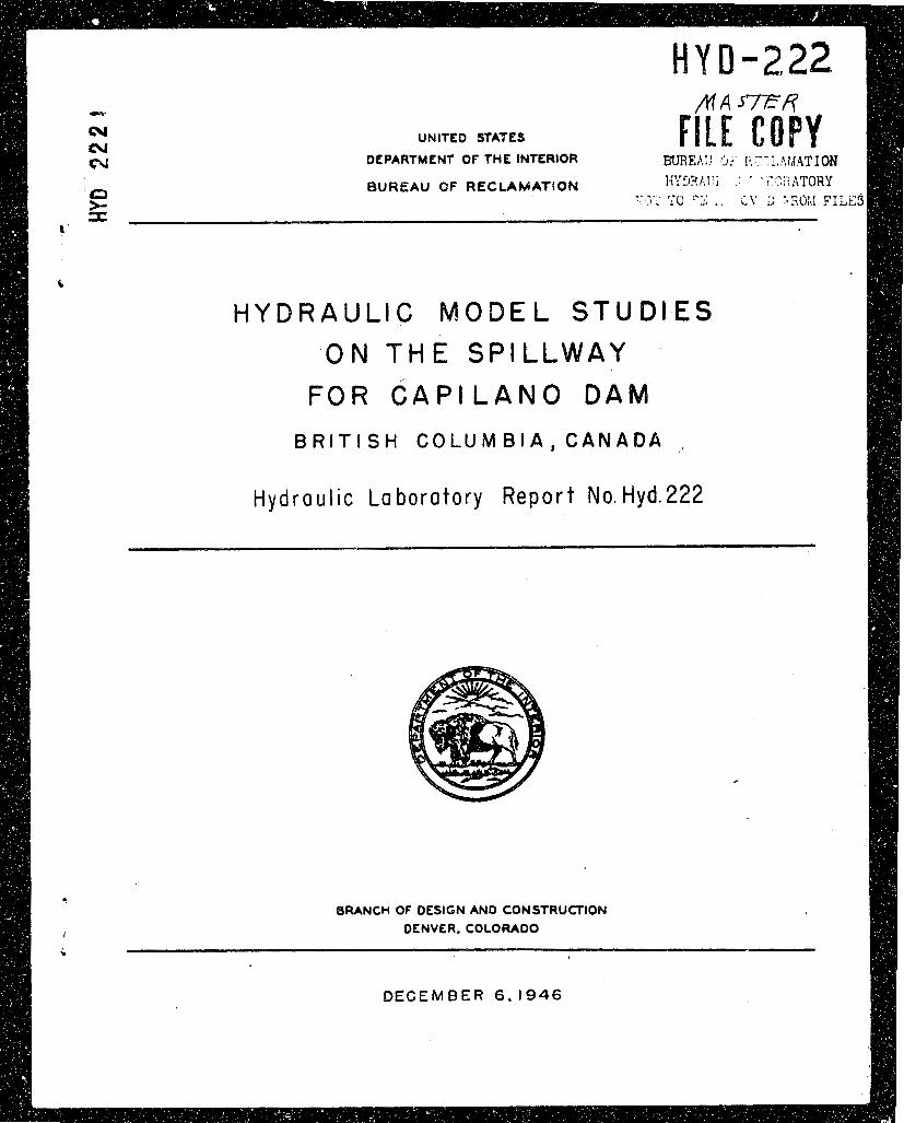
UNITED STATES
DEPARTMENT OF THE INTERIOR BUREAil 0:' I ~ . ' : : - ~ , ~ I I A T I O N
BUREAU OF RECLAMATfON Ii'i3?lhl'; : ' ' I"?fiiATORY c : : . , ;, \: [; 7 , X()M F'I L
C
H Y D R A U L I C M O D E L S T U D I E S O N T H E SPILLWAY
F O R C A P I L A N O D A M
B R I T I S H C O L U M B I A , C A N A D A
Hydraulic Labo ra to ry Repo r t No. Hyd.222
BRANCH O f DESIGN AND CONSTRUCTION DENVER. COLORADO
l
i
DECEMBER 6.1946

UMI TED STATES L!EPiS?b:l-h'T OF Till: II~ITI;?IOR
BU3EAU OF R~;CLIt.';hTIOM
Eranch of i~esie:i and Construction Labor.atory Report No. 222 Zriginccring and Ceolo/:ical Control Hydraulic Laboratory
~ n d Research Division Co~:p.Jiled by: Een R . I3lcckwell Denver, Colorado %viewed by: J. E. Xarnock and ilecember 6 , 19A6 J. K . Era3.lcy
Subject : Hydl*i~ulic model s t t idies on t h e sp i l lway f o r C ~ p i l u n o 2m.- E f i t i s h Colurnbin, Cantida.
On karch 22, 1946, zn q r e r m e n t (Cont rac t No. 12r-15805) wa:> rece
between t h e United S ta tes , represented by t h e Chief Znfineer, hrt';a
of !?eclamhtion, and t he I n t e r n a t i o n a l Engineering :o~pzny, Lknver,
Cclorido, t he iiureau of :?eclamztion uould co;iduct hydraul ic
model. t .ests of the s? i l lway and o u t l e t works l o r t h e Cani1ar.o Dam
being designed f o r the Ci ty of Vancouver, b r i t i s h Columbia. The
des igns h a v ~ been scbmit ted by Kr. J. J. Hammond. Wr, John L. Savage
i s consul t ing engineer f o r t he pro jec t .
The pr inc ipa l f e a t u r e s of the tiesign t o be inves t iga t ed were:
1. Flow cond i t ions i n the approach t o the spi l lway
2. The c h a r c c t e r i s t i c s and e f f i c i e n c y of t h e overflow
c r e s t s e c t i o n
3 . Plow cond i t ions i n thc chute w,d s t i l l i n g - p o o l
1.. The ~tXl€!r€il operc t ion of t h e o u t l e t works.
The Cepilnno Dim of t h e Grea ter Vmcouver liater I j i s t r i c t i s
located on t h e Capibmo River 2 miles ebove l'iorth Vzricouver, P r i t i s h
Columbie, Figure 1. This concrete-gravi ty type s t r u c t u r e k 5 l l rive
300 f e c t abovc bedrock, Figure 2. %e hverage hydraul ic head w i l l be
2b0 f e e t . River flow, p a s t t h e dm, fill b6 c o n t r o l l e d one 70-
by 23-foot arum eate znd Ly two r i v e r o u t l e t s w i th 5- kj. t - foo t

high-prcssure slide gateo. The sp i l lway I s designcd f o r a rncudnum
discharge (1,000-~eiir f lood) of 43,000 second-feet. The 100-yew
f'looti was conoidcrca t o be 33,OGC second-feet. The domestic water
supp ly will be ralecood through two 7 2 i n c h d i m e l . e r t u n n e l s cu~d
con t ro l l ed by two 5- by 6-foot high-pressure s l i d a ~ a t c u . An 8-foot
eiarnetcr connect ion k k 1 1 Le provided i n t h e face of t h e darn f o r a
penstock f o r f u t u r e power dcvolopmcnt.
The r c s ~ l t s of t h e hycrauiic mocel s t u c i e s of' the Capilano Lm
nls;r be s m i a r i z e d au follows:
1. The flow conditio;iti i n t h e &p?roach t o t h e sp i l lway
were s 6 ~ t i s f a c t o r y .
2, To ?ass the ~nadrnurn discharge of &3,000 second-feet,
t l ~ c mx<i:zxnt r e s e r v o i r e l e v a t i o n will be 577.
3. ;bile t h e r e kicts conaidcrable sp lashizp over the chu te
t r a i k r y walls a t the: h i c t ~ e r d ischarges , the opera t ion wcs co1:-
s i d e r t a acceptable bccituse of t h c e x c e l l e n t rock i n t h e v i c i n i t y
01' t h e dm. Operution of t h e s t i l l i n ~ - k J a s i n as o r i g i n a l l y d e s l ~ n c d
v,as e n t i r e l y snt isfactor; .
4 . Ge:iel.cl e x t e r i o r ope ra t ion o f t h e r i v e r o t i t l e t s a t f u l l -
ghtt opcnini: w ~ s s a t i s f a c t o r y f o r ali conbinzt ions of flow.
SESC?iTTION CF THE: hOUXL
;, 1:60 s c a l e i:yaraulic model of Capilsno Dam was cons t ruc ted a t
the new Eureau of 2eclwncation Hydraulic Laboratory loca ted i n t h e Genver
Federal Center , Denver, Colorado. S t m d a r d c o n s t r u c t i o n was used i n
tne codel. 'hc head and o u t l e t boxes were of t imber and l i ned with
sheet ~net;ll . 'Be c r e s t , r i ve r or:tlets, end upper pa r t of t h e chute
were cons t ruc ted of sheet metal, while t h e s t i l l i r l g - l a s i n wcs cons t ruc ted 0
of wood. The topography i n t h e o u t l e t box who constructed of wood &la

layout is show i n F i g r e 3 . The model, ready f o r opera t ion , i s
shown i n Fihare LA,
TIE IXVI!STlGATION
The cipproach. Kith t h e except ion of t h e t r a s h r a c k f o r t h e
comestic water supply, t he cpprooch t o t h e sp i l lwsy i s s t r a i g h t and
symmetrical and, therefore , p re sen t s no hydraul ic problem. 2'he t rash-
r ack i s l o c a t e d c l o s e r t o t h e spillway t h a n i s custonary, so model
s tud ies were made on t he spi l lway ope ra t ion and e f f i c i e n c y w i t h nnd
without thc t r a sh rack s t :*~cture. ?'fie t r a sh rack s t r u c t u r e d i d not
e f f z c t t he opera t ion o r e f f i c i e n c y o r t h e spi l lway i n the nodcl.
F igure 5 A shows th:? cppronch cond i t ions a t the maximum d i s c h a r ~ e of
i 3 ,OCO second-feet.
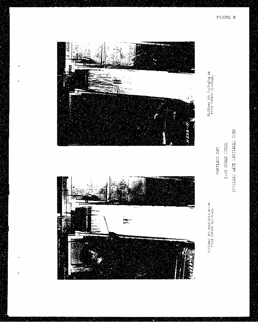
'i'he overflow c rcs t s e c t i o n . F l o ~ c o r ~ d i t i o n s ct the c r c s t were
s n t i s f i ~ c t o r j . f o r t h e des i~ ;n 2 s subnlitter',. The nsppe was complctcly
a e r ~ t c c with t h e drum gate i n r c i s e c positions cxcrpt a t vcry low
heads when the shee t of mter from t h e c r e s t d i a xo t c l e a r the s e l f -
&eratin: ~ i e r s . .T"r.is l a t t e r conc i t ion , while not se r ious , m2y be avoided
by usirii; t h c r i v e r o u t l e t s i n s t e a d of t h e spillwby fot- vary small
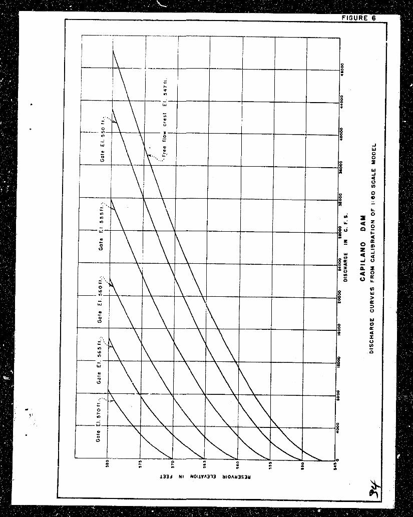
discharges. The c o e f f i c i e n t of d i scha rge z t r~aximm r e s e r v o i r e l e v c t i o n
of 575 f c ~ t was found t o bt: 3.71, as con;parlxl t o the acsil:n c o e f f i c i e n t
of apprcrxbxteuly A.11,. The ciiVl"crence i n c o e f f i c i e n t s r e su l t ed ir, a
mainurn f ree d ischarge of 3E,lr00 second-feet, as comparec Lo a dischax-ge
o f lr3,GaG secoad-feet f o r the maximum des ign hcad. h e t o t h e nature
o f the t o p o ~ r i q h y of t h e s i t e , n lonee? spillway crust was found t o be
::necor!omical. It \c.cls theref o r e decided t o increase t h c mcixirrnun r e s e r v o i r
e l cvc t ion by 2 f e e t t o bring! tile sp i l lway capaci ty t o t h e I-equired
&?,OW second-feet. The mo(?cl t e s t s indici i ted a maximum r e s e r v o i r water
surfrice o r e l e v a t i o n 57:7.0, as cornp5rec1 to t h c c;esign water su r face of
e l e v a t i o n 575.0 f ee t . l~t.ed-dischzr&c curves obtuined from the model
c a l i b r a t i o n are shown i n F i f l r e 6 f o r t h e free c r e s t and scverSQ

t h e same cond i t ions arc shown on Figure 7. The c !lute. There wzs consicieruble splashing over t h e chilte t r a i n i n g
w a l l s c i t spill.w&y discharges o f over 30,000 second-feet. The spillbray
j e t expanding fron: the 70-foot spillway gate s e c t i o n t o the 8 G f o o t
chute conlbincd h4th t h e steep s lope of the chute produced f i n s of w s t c r
d o n g t h e t r a i n i n ~ wullo. The ma jo r i ty of t h e splbsfiing was r o d u c e d
by these f i n s . "Sea wall 3," Figure 5B, were e f f e c t i v e i n conf in ing t h e
opleshing t o the chute. Considering t h e s o l i d rock i n the canyon
ealls , t h e ~ L n o r nz ture of the sp lashing , ano t h e infrequency of
occurrence of the h igher dischart:es, t h e Itsen w a l l t f design was discarded
anc t h c o r i g i n a l w a l l design r e t a ined .
Consiaereble s? lash in& occurrcd hcithin the chuto a u r i n ~ spillway
opere t ion ~ 5 t h t he d m ate i n r a i scd pos i t i ons . For s e v e r ~ i l combinations
of cischiir&e ma gate opening t h e j e t from the ~ ? i l l w & y impinged i n t he
r i v e r outlet openings zs i s shown i n Figure 6. The c o ~ b i n a t i o n s o f
discharge and gate p o s i t i o n t h a t t h i s can occur a r e so f r e q ~ e c t t h a t no
i t t ~ ~ i : t i s being mede t o l i m i t opera t ion t o avoici t h i s condi t ion . It i s
not sxpcctcc t h a t any camage k r i l l r e s u l t from t h e sp i l lway sheot s t r i k i n g
t5c o u t l e t t r o u ~ h s . li t e s t on t i le nrototype vri l l be more convincing
as t.o t h i s po in t ,
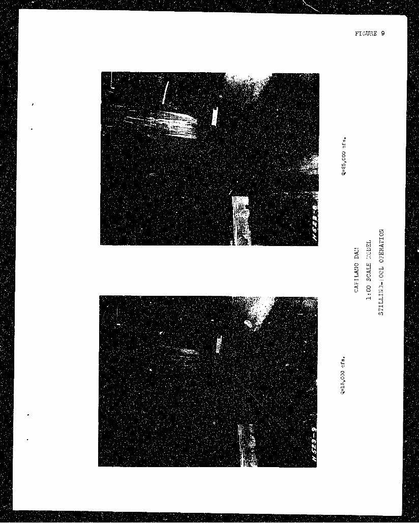
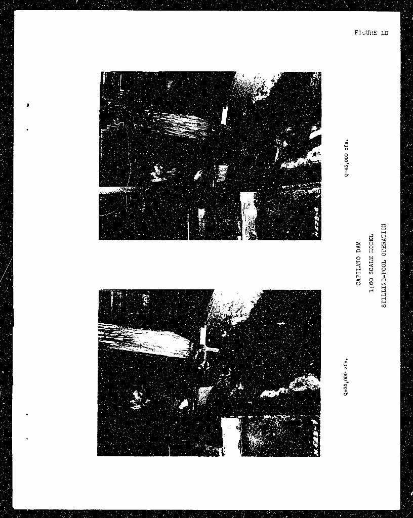
?he stillmy_-0091. Operation of thit s t i l l i ng -poo l was sat isfbrctory
at a l l o ischnrges. r.t discharges of over 30,000 second-feet, the a c t i o n
over t h e end s i l l was r h t h e r rough bu t was not s e r i o u s because o f t h e
s o l i d rock ir, t h e chnyon. X t 43,000 second-iect, ti drop i n the t a i l s a t c r
e l c v t t i o n o f over 6 f e e t below normal was reqllirec: t o sweep the hydrhulic
ju~np of': the ilprori. /.t 33,000 second-feet, t h e drop i n t a i l w a t e r
e l f -va t ion wbs increased t o 12 f e e t t o ccconpl i sh the same r u 5 u l t . At
discharges of 25,000 o e c ~ n a - f e e t and lest;, t h c c o n t r o l s e c t i o n i n t h e
r i v e r im:lcdiately downstream from t h e s t i l l i ng -no61 rnaintairlea s u f f i c i e n t
t a i l w a t e r e l ~ v a t i o n t o prcvcnt t h e juril? xazhinl: off the ripron under my
condi t ion . :~ t i l l i ng -poo l ope ra t ion with normal tc?il\mtcr e l e v a t i o n s i s
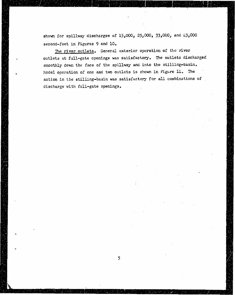
second-feet in Figures 9 and 10.
The r i v e r o u t l e t s . General e x t e r i o r opera t ion of t h c river
o u t l e t s a t fu l l -gate openings was s a t i s f a c t o r y . The o u t l e t s discharged
smoothly down t h e face of t h e spi l lway and i n t o t h e s t i l l ing-bas in .
Fiodel opera t ion of one and two o u t l e t s i s shown i n k Y g ~ ~ r o 11. ?'he . ac t ion i n t h e s t i l l ing-bas in was s a t i s f a c t o r y f o r all combinations of
discharge with full-gate openincs.


FIGURE 2
- 25' Q~ucrrron tunnel
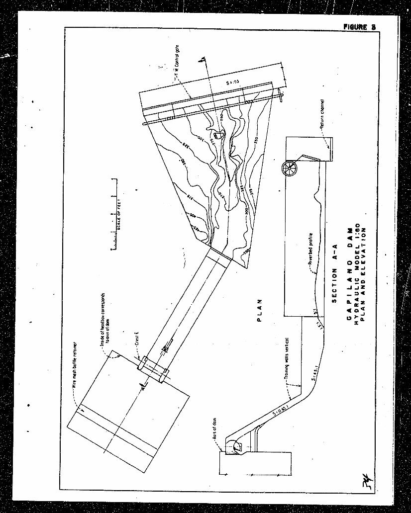

FIGURE 4
M L7 d AJ
d
m (4 0 .
P i + Q) 0
TI 0 0 t i 0
h O. d C)
s w d !I
ze (4 10
m'
d 3 2 " 3 5 2 H rn a 4 0
'p. rl
h
3 & . d T: 0 0 ad z 2 P, Q m n s 0 rl d C, d 0 ah V)
-4

S E A W A L L DESIGN
E. L~.;.t,iila 01' ciiutu tr11l:lini-wnlln.
C A i ' I LK!C DR.:
1 :dO SCALE :.:i'i;L'i,

ti1 o 1: !.I
- 4 1: UI-I
L : i : - 4 C>
! j l .1< 1. 0 *,
I )
0 13 LI .-I -, 1) 1
'i. 0 m .: I. d l!'
d :- - 4 - 8
bl . h U)